1
Agilent B1500A
Semiconductor Device
Analyzer
User’s Guide
Agilent Technologies
Notices
© Agilent Technologies 2005, 2006, 2007,
2008
No part of this manual may be reproduced in
any form or by any means (including electronic storage and retrieval or translation
into a foreign language) without prior agreement and written consent from Agilent
Technologies, Inc. as governed by United
States and international copyright laws.
Manual Part Number
B1500-90000
Edition
Edition 1, July 2005
Edition 2, December 2005
Edition 3, April 2006
Edition 4, January 2007
Edition 5, June 2007
Edition 6, November 2007
Edition 7, October 2008
Agilent Technologies, Inc.
5301 Stevens Creek Blvd
Santa Clara, CA 95051 USA
Warranty
The material contained in this document is provided “as is,” and is subject to being changed, without notice,
in future editions. Further, to the maximum extent permitted by applicable
law, Agilent disclaims all warranties,
either express or implied, with regard
to this manual and any information
contained herein, including but not
limited to the implied warranties of
merchantability and fitness for a particular purpose. Agilent shall not be
liable for errors or for incidental or
consequential damages in connection with the furnishing, use, or performance of this document or of any
information contained herein. Should
Agilent and the user have a separate
written agreement with warranty
terms covering the material in this
document that conflict with these
terms, the warranty terms in the separate agreement shall control.
Technology Licenses
The hardware and/or software described in
this document are furnished under a license
and may be used or copied only in accordance with the terms of such license.
Restricted Rights Legend
If software is for use in the performance of a
U.S. Government prime contract or subcontract, Software is delivered and licensed as
“Commercial computer software” as
defined in DFAR 252.227-7014 (June 1995),
or as a “commercial item” as defined in FAR
2.101(a) or as “Restricted computer software” as defined in FAR 52.227-19 (June
1987) or any equivalent agency regulation or
contract clause. Use, duplication or disclosure of Software is subject to Agilent Technologies’ standard commercial license
terms, and non-DOD Departments and
Agencies of the U.S. Government will
receive no greater than Restricted Rights as
defined in FAR 52.227-19(c)(1-2) (June
1987). U.S. Government users will receive
no greater than Limited Rights as defined in
FAR 52.227-14 (June 1987) or DFAR
252.227-7015 (b)(2) (November 1995), as
applicable in any technical data.
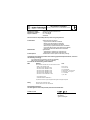
DECLARATION OF CONFORMITY
According to ISO/IEC Guide 22 and CEN/CENELEC EN 45014
Manufacturer’s Name:
Manufacturer’s Address:
Supplier’s Address:
Agilent Technologies International sarl
Rue de la Gare 29
CH - 1110 Morges
Switzerland
Declares under sole responsibility that the product as originally delivered
Product Name:
Model Number:
Product Options:
Semiconductor Device Analyzer
High Power Source/Monitor Unit Module,
Medium Power Source/Monitor Unit Module,
High Resolution Source/Monitor Unit Module,
Multi Frequency Capacitance Measurement Unit Module,
High Voltage Semiconductor Pulse Generator Unit Module,
Waveform Generator/Fast Measurement Unit Module
Agilent B1500A
Agilent B1510A, Agilent B1511A, Agilent B1517A,
Agilent B1520A, Agilent B1525A, Agilent B1530A
This declaration covers all options of the above product(s)
complies with the essential requirements of the following applicable European Directives, and carries
the CE marking accordingly:
Low Voltage Directive (73/23/EEC, amended by 93/68/EEC)
EMC Directive (89/336/EEC, amended by 93/68/EEC)
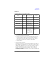
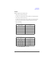
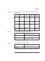
and conforms with the following product standards
Limit
EMC
Standard
IEC 61326:2002 / EN 61326:1997 +A1:1998 +A2:2001 +A3:2003
CISPR 11:1997 / EN 55011:1998
IEC61000-4-2:1995 / EN61000-4-2:1995
IEC 61000-4-3:1995 / EN61000-4-3:1995
IEC 61000-4-4:1995 / EN61000-4-4:1995
IEC 61000-4-5:1995 / EN61000-4-5:1995
IEC 61000-4-6:1996 / EN61000-4-6:1996
IEC 61000-4-11:1994 / EN61000-4-11:1994
Group 1 Class A
4 kV CD, 8 kV AD
3 V/m, 80-1000 MHz
0.5 kV signal lines, 1 kV power lines
0.5 kV line-line, 1 kV line-ground
3 V, 0.15-80 MHz
1 cycle, 100%
Canada: ICES-001:1998
Australia/New Zealand: AS/NZS 2064.1
The product was tested in a typical configuration with Agilent Technologies test systems.
Safety
IEC 61010-1:2001 / EN 61010-1:2001
Canada: CSA C22.2 No. 1010.1:1992, NRTL/C
Supplementary Information:
This DoC applies to above-listed products placed on the EU market after:
October 01, 2008
Date
Toshiyuki Kawaji
QA Manager
Agilent Technologies
•
Herstellerbescheinigung
GEÄUSCHEMISSION
Lpa < 70 dB
am Arbeitsplatz
normaler Betrieb
nach DIN 45635 T. 19
•
Manufacturer’s Declaration
ACOUSTIC NOISE EMISSION
Lpa < 70dB
operator position
normal operation
per ISO 7779
NOTE
This ISM device complies with Canadian ICES-001.
Cet appareil ISM est conforme ?Hla norme NMB-001 du Canada.
This product complies with the WEEE Directive (2002/96/EC) marking requirements.
The affixed label indicates that you must not discard this electrical/ electronic product
in domestic household waste.
Product Category: With reference to the equipment types in the WEEE Directive
Annex I, this product is classed as a “Monitoring and Control instrumentation”
product.
Do not dispose in domestic household waste.
To return unwanted products, contact your local Agilent office, or see
www.agilent.com/environment/product/ for more information.
EasyEXPERT is a trademark of Agilent Technologies. Microsoft and Windows are registered trademarks of Microsoft
Corporation. All other trademarks are the property of their respective owners.
Safety Summary
The following general safety precautions must be observed during all phases of
operation, service, and repair of this instrument. Failure to comply with these
precautions or with specific warnings elsewhere in this manual may impair the
protections provided by the equipment. In addition, it violates safety standards of
design, manufacture, and intended use of the instrument. Agilent Technologies, Inc.
assumes no liability for customer’s failure to comply with these requirements.
NOTE
Agilent B1500 complies with INSTALLATION CATEGORY II for mains input and
INSTALLATION CATEGORY I for measurement input terminals, and POLLUTION
DEGREE 2 defined in IEC 1010-1.
Agilent B1500 is an INDOOR USE product.
NOTE
LED in Agilent B1500 is Class 1 in accordance with IEC 825-1. CLASS 1 LED PRODUCT.
•
GROUND THE INSTRUMENT
This is Safety Class I instrument. To minimize shock hazard, the instrument chassis
and cabinet must be connected to an electrical ground. The power terminal and the
power cable must meet International Electrotechnical Commission (IEC) safety
standards.
•
DO NOT OPERATE IN AN EXPLOSIVE ATMOSPHERE
Do not operate the instrument in the presence of flammable gases or fumes.
Operation of any electrical instrument in such an environment constitutes a
definite safety hazard.
•
KEEP AWAY FROM LIVE CIRCUITS
Operation personnel must not remove instrument covers. Component replacement
and internal adjustments must be made by qualified maintenance personnel. Do
not replace components with power cable connected. Under certain conditions,
dangerous voltages may exist even with the power cable removed. To avoid
injuries, always disconnect power and discharge circuits before touching them.
•
DO NOT SERVICE OR ADJUST ALONE
Do not attempt internal service or adjustment unless another person, capable of
rendering first aid and resuscitation, is present.
•
DO NOT SUBSTITUTE PARTS OR MODIFY INSTRUMENT
Because of the danger of introducing additional hazards, do not install substitute
parts or perform any unauthorized modification to the instrument. Return the
instrument to a Agilent Technologies Sales and Service Office for services and
repair to ensure that safety features are maintained.
•
DANGEROUS PROCEDURE WARNINGS
Warnings, such as example below, precede potentially dangerous procedures
throughout this manual. Instructions contained in the warnings must be followed.
WARNING
Dangerous Voltage, capable of causing death, are present in this instrument. Use
extreme caution when handling, testing, and adjusting.
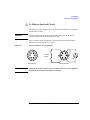
Safety Symbols
The general definitions of safety symbols used on equipment or in manuals are listed
below.
Instruction manual symbol: the product will be marked with this symbol when it is
necessary for the user to refer to the instruction manual in order to protect against
damage to the instrument.
Indicates dangerous voltage and potential for electrical shock. Do not touch terminals
that have this symbol when instrument is on.
Protective conductor terminal. For protection against electrical shock in case of a fault.
Used with field wiring terminals to indicate the terminal which must be connected to
ground before operating equipment.
Frame or chassis terminal. A connection to the frame (chassis) of the equipment which
normally includes all exposed metal structures.
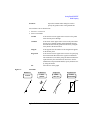
>
`
Indicates earth (ground) terminal.
Alternating current.
Direct current.
STANDBY (Supply).
&$7,
Means INSTALLATION CATEGORY I. Measurement terminals on the rear panel comply
with INSTALLATION CATEGORY I.
WARNING
The warning sign denotes a hazard. It calls attention to a procedure, practice, condition
or the like, which, if not correctly performed or adhered to, could result in injury or
death to personal.
CAUTION
The caution sign denotes a hazard. It calls attention to an operating procedure,
practice, condition or the like, which, if not correctly performed or adhered to, could
result in damage to or destruction of part or all of the product.
HIGH VOLTAGE SHOCK HAZARD
Agilent B1500 can force dangerous voltages (200 V for HPSMU, and 100 V for
MPSMU/HRSMU) at the force, guard, and sense terminals. To prevent electric
shock hazard, the following safety precautions must be observed during the use of
Agilent B1500.
•
Use a three-conductor AC power cable to connect cabinet (if used) and Agilent
B1500 to an electric ground (safety ground).
•
If you do not use Agilent 16442 Test Fixture, make sure to connect the Interlock
terminal to a switch that turns off when the shielding box access door is opened.
•
Confirm periodically that interlock function works normally.
•
Before touching the connections of the force, guard, and sense terminals, turn
Agilent B1500 off and discharge any capacitors whenever possible. If you do
not turn Agilent B1500 off, complete “all” of the following items, regardless of
any Agilent B1500 settings.
•
•
Terminate measurement by pressing Stop key, confirm that the Measurement
status indicator is not lit.
•
Confirm that the High Voltage indicator is not lit.
•
Open the shielding box access door (open the Interlock terminal).
•
Discharge any capacitors if the capacitance is connected to an SMU.
Warn workers in the vicinity of Agilent B1500 about dangerous conditions.
高電圧感電注意
Agilent B1500 のフォース、ガード、センス端子には、危険電圧が出力されることが
あります(HPSMU の場合は最大± 200 Vdc、MPSMU/HRSMU の場合は最大± 100
Vdc)
。感電事故防止のため、必ず以下の事柄を守ってください。
•
3 極電源ケーブルを使用して Agilent B1500 を設置すること。
•
Agilent 16442 テスト・フィクスチャ以外のフィクスチャ、あるいはプローバを
使用する場合には、シールド・ボックスにインターロック回路を接続すること。
インターロック回路とは、シールド・ボックスの蓋を開けた時に Agilent B1500
の Interlock 端子を開放にすることができる回路のことをいいます。
•
インターロック機能が正常であることを定期的に確認すること。
•
フォース、ガード、センス端子に繋がる接続部に触れる前には、測定器の電源
を切ること。また、測定系にキャパシタが接続されている場合は、キャパシタ
を放電すること。電源を切らない場合は、以下の事項を全て実施すること。
•
•
Stopキーを押してMeasurementインジケータが消灯したことを確認すること。
•
高電圧警告(High Voltage)インジケータが消灯していることを確認するこ
と。
•
シールド・ボックスの蓋を開ける(Interlock 端子を開放する)こと。
•
キャパシタが SMU に接続されているならば、キャパシタを放電すること。
周囲のほかの作業者に対しても、高電圧危険に対する注意を徹底すること。
PRECAUTIONS POUR COMMOTION A HAUTE TENSION
Une tension dangereuse (max. ± pour HPSMU; 200 Vdc, max. ± pour MPSMU/
HRSMU; 100 Vdc) émanant du dispositif Agilent B1500 peut être sortie aux bornes
de force, d'appareil de protection ou de détection. Les précautions suivantes doivent
être obserées contre commotion électrique accidentelle:
•
Mettre à la terre le dispositif Agilent B1500 au moyen du câble d'alimentation
tripolair.
•
En cas de hors service du dispositif d'essai, FIXTURE Agilent 16442, connecter
les bornes de verrouillage (Interlock) de façon à ce que soit ouverte lorsque le
couvercle de la boîte de blindage est ouvert.
•
Essayer périodiquement le fonctionnement normal de verrouillage.
•
Avant de toucher la partie connexion à partir des bornes de force, d'appareil de
protection et de détection, mettre hors tension le dispositif Agilent B1500. Et, en
cas de condensateurs connectés au circuit de mesure, décharger ces
condensateurs. Lorsque l'alimentation n'est pas mise hors tension, les 4
instructions suivantes doivent être exécutées:
•
•
Finir la mésure en appuyant sur la touche “Stop”; verifier que l'indicateur
“Measurement” n'est pas allumé.
•
S'assurer que soit allumé l'indicateur d'alarme de la haute tension.
•
Ouvrir le convercle de la boîte de blindage (Ouvrir les bornes de
verrouillage).
•
En cas de condensateurs connectés à SMU, décharger les condensateurs.
Alerter d'autres personnes autour de vous contre le danger de haute tension.
Achtung! Gefährliche Spannung
Von den Geräten Agilent B1500 können Spannungen an den Anschlüssen “Force,
Guard und Sense” von bis zu 200 V ausgehen. Um elektrischem Schlag vorzubeugen, ist bei der Benützung der Geräte Agilent B1500 folgendes zu beachten:
•
Erden Sie das Kabinett (falls verwendet) sowie die Geräte Agilent B1500 mittels
dreiadriger Netzleitungen.
•
Wenn die Meßfassung, Agilent 16442, zwar angeschlossen, jedoch nicht
verwendet wird, schließen Sie die Verriegelungsklemme (Interlock) so an, daß
bei geöffnetem Deckel die Stromzuführung zu Agilent 16442 auf jeden Fall
unterbrochen wird.
•
Vergewissern Sie sich regelmäßig daß die Verriegelungsfunktion korrekt
arbeitet.
•
Schalten Sie die Geräte Agilent B1500 aus, und entladen Sie alle Kapazitäten
bevor Sie die Anschlüsse “Force, Guard und Sense” berühren. Falls Sie die
Geräte Agilent B1500 nicht ausschalten, führen Sie unabhängig von den
Geräteeinstellungen folgende Schritt durch:
•
•
Beenden Sie die gegenwärtige Messung durch Drücken der Stop Taste (die
Measurement Leuchtdiode erlischt).
•
Vergewissern Sie sich daß die Hochspannungswarnlampe erloschen ist.
•
Öffnen Sie den Deckel der Meßfassung Agilent 16442 (die
Verriegelungsklemme (Interlock) öffnen).
•
Entladen Sie alle an SMUs angeschlossenen Kondensatoren (falls
vorhanden).
Informieren Sie Personen in unmittelbarer Nähe der Geräte Agilent B1500 über
die Gefährlichkeit der bestehenden Hochspannung, und sichern Sie den Zugang
zum Prüfplatz zum Schutz Dritter.
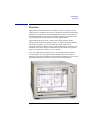
Precautionary Statement
Agilent B1500 Semiconductor Device Analyzer operates in the Microsoft Windows XP
Professional environment. Agilent B1500 requires Agilent EasyEXPERT software, a
specially-designed Windows XP application program.
•
About guarantee and support for Agilent B1500
Agilent Technologies guarantees and supports the performance of Agilent B1500
for the same condition as the preload condition when shipped from the factory.
•
About updating Agilent EasyEXPERT and the Windows Update
Agilent Technologies confirms the operation of Agilent EasyEXPERT patch
programs and important Windows security patches, and provides recommended
update information. Visit Agilent B1500 support site, download the patches, and
perform the software update.
•
About Windows XP application programs and peripherals (including driver)
Using commercial products on Agilent B1500 is your responsibility. Agilent
Technologies cannot provide compatibility information for commercial products. If
problems arise, perform Agilent B1500 system recovery.
•
About servicing
Bench repair service is available at your nearest Agilent Technologies service
center. Be aware that the B1500 configuration might be updated to the latest one
without notice because of support issues.
The internal hard disk drive (HDD) might be initialized during servicing. If
peripherals are connected, they will be removed.
When Agilent B1500 is returned, the internal HDD might be initialized. Peripherals
will be returned separately.
•
Other notes
•
Back up the internal HDD to prevent loss of data by accident or failure.
•
Protect Agilent B1500 from computer viruses.
•
If you connect Agilent B1500 to the network, take care to protect it from
computer virus.
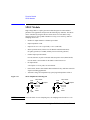
Working in Comfort
To optimize your comfort and productivity, it is important that you set up your work area
correctly and use your instrument properly. With that in mind, we have developed some
set-up and use recommendations for you to follow based on established ergonomic
principles. Improper and prolonged use of keyboards and input devices are among
those tasks that have been associated with repetitive strain injury (RSI) to soft tissues
in the hands and arms. If you experience discomfort or pain while using the instrument,
discontinue use immediately and consult your physician as soon as possible. For more
information on RSI you may wish to consult the About Repetitive Strain Injury section.
Please study the recommendations described below. Included there are references to
relevant parts of international standards, regulations and guidelines, such as ISO 9241
and the European Community Display Screen Equipment directive. You may also wish
to consult your employer’s human resources department or other relevant departments
for guidance specific to your company.
About Repetitive Strain Injury
Because your comfort and safety are our primary concern, we strongly recommend
that you use the instrument in accordance with established ergonomic principles and
recommendations. Scientific literature suggests that there may be a relationship
between injury to soft tissues -especially in the hands and arms- and prolonged
improper use of keyboards or other equipment requiring repeated motions of the
hands and forearms. This literature also suggests that there are many other risk
factors that may increase the chance of such injury, commonly called Repetitive Strain
Injury.
What is RSI?
Repetitive Strain Injury (RSI -also known as cumulative trauma disorder or repetitive
motion injury) is a type of injury where soft tissues in the body, such as muscles,
nerves, or tendons, become irritated or inflamed. RSI has been a reported problem for
those who perform repetitive tasks such as assembly line work, meatpacking, sewing,
playing musical instruments, and computer work. RSI also has been observed in those
who frequently engage in activities such as carpentry, knitting, housework, gardening,
tennis, windsurfing and lifting children.
What causes RSI?
The specific causes of RSI have not been established. Nevertheless, the incidence of
RSI has been associated with a variety of risk factors, including:
•
Too many uninterrupted repetitions of an activity or motion.
•
Performing an activity in an awkward or unnatural posture.
•
Maintaining static posture for prolonged periods.
•
Failing to take frequent short breaks.
•
Other environmental and psychosocial factors.
In addition, there have been reports associating the occurrence of RSI with the use of
keyboards, mice, and other input devices. Also, certain medical conditions, such as
rheumatoid arthritis, obesity and diabetes, may predispose some people to this type of
injury.
What if I experience discomfort?
If you are experiencing any discomfort, seek professional medical advice immediately.
Typically, the earlier a problem is diagnosed and treated, the easier it is to resolve.
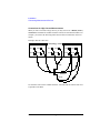
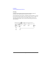
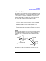
Mice and Other Input Devices
Various aspects of using mice and other input devices may increase your risk of
discomfort or injury. Observing the following recommendations may reduce that risk.
•
Try to keep your hand, wrist, and forearm in a neutral position while using your
mouse or other input device.
•
If you use your thumb to rotate the ball on a trackball or spaceball, keep it in a
relaxed, natural shape, and maintain a neutral posture in your hand, wrist, and
forearm.
•
Hold the mouse gently by draping your fingers over it. Keep your hand relaxed and
fingers loose. Do not grip the mouse tightly.
•
It takes very little pressure or force from your fingers to activate the buttons or
scroll wheel on your mouse, scrolling mouse, trackball, or other input device.
Using too much force can place unnecessary stress on the tendons and muscles
in your hands, wrists, and forearms.
•
If you are using a scrolling mouse, be sure to keep your fingers and hand in a
relaxed, neutral position when activating the scroll wheel. Also, this type of mouse
features software that can minimize the number of mouse movements or button
clicks.
•
When using a mouse, trackball, or other input device, position it as close to the
keyboard as possible, and keep it at the same level as you do not have to stretch
while using it.
•
Be sure to keep your mouse and trackball clean. Regular removal of accumulated
dust and dirt helps ensure proper tracking and reduces unnecessary hand and
wrist motions.
In This Manual
This manual describes the front panel operation, installation, and functions of Agilent
Technologies B1500. This manual consists of the following chapters:
•
Chapter 1, “Getting Started”
This chapter describes the basic operations of Agilent B1500.
•
Chapter 2, “Introduction”
This chapter describes overview, specifications, accessories and options of
Agilent B1500.
•
Chapter 3, “Installation”
This chapter explains how to install Agilent B1500, and how to connect the device
under test to a test fixture.
•
Chapter 4, “Using EasyEXPERT”
This chapter provides the reference information of Agilent EasyEXPERT software.
•
Chapter 5, “Classic Test Definition”
This chapter provides the reference information of the classic test definition.
•
Chapter 6, “Application Test Definition”
This chapter provides the reference information of the application test definition.
•
Chapter 7, “Function Details”
This chapter explains the several functions and initial settings of Agilent B1500.
•
Chapter 8, “Built-in Programming Tool”
This chapter provides information about the built-in mathematical functions and
read out functions.
•
Chapter 9, “If You Have a Problem”
This chapter explains how to solve a problem if you encounter any problem, and
describes error codes. This chapter also describes how to perform the system
recovery and the data backup/recovery.
•
Chapter 10, “Application Library and Utilities”
NOTE
To get the latest firmware/software/electronic manuals/support information, visit
Agilent Technologies support site (http://www.home.agilent.com), and click
Additional Test & Measurement Products > Parametric Test, click Semiconductor
Parameter/Device Analyzer Series, and click B1500A Semiconductor Device Analyzer.
You can reach Agilent B1500A support site.
Online Documents
The following electronic documentation files are stored in Agilent B1500’s internal
hard disk drive. The files provide the information of how to use Agilent B1500 and
Agilent EasyEXPERT software.
Folder: C:\Program Files\Agilent\B1500\Documents
•
B1500_help.chm
A part of Agilent B1500A User’s Guide. This is the online help that can be opened
from the Help menu on the EasyEXPERT main screen.
•
B1500_Self_Trng.mht
Agilent B1500A Self-paced Training Manual that can be opened by a browser
Utilities
The following utility programs are stored in Agilent B1500’s internal hard disk drive.
For details, see “Application Library and Utilities” on page 10-1.
•
License Management Tool
This is the GUI based program used to manage the license of the EasyEXPERT
Plus edition and the Desktop EasyEXPERT Plus edition.
•
Setup File Converter
This is the GUI based program used to convert Agilent 4155/4156 setup file (.MES
file) and create the EasyEXPERT setup file (.XTS file).
•
Prober Control Scripts
Execution files that can be used to control the chuck movement of a prober. For
details, see the readme file.
•
SetupFileConverter.exe
This is the script version of the Setup File Converter.
•
sleep.exe
Execution file that can be used to put a wait time in the test execution flow of an
application test.
•
XSLT Filters
XSLT filters that can be used by the Export in My Format function. They are filter
files for changing the format of the test result record.
NOTE
The utility programs are just sample. If the samples damage your devices, Agilent
Technologies is NOT LIABLE for the damage. And the operation is not guaranteed.
Contents
1. Getting Started
To Turn On/Off B1500A . . . . . . . . . . . . . . . . . . . . . . . . . . . . . . . . . . . . . . . . . . . . . . . . . 1-3
To Turn B1500A On . . . . . . . . . . . . . . . . . . . . . . . . . . . . . . . . . . . . . . . . . . . . . . . . . . . 1-4
To Turn B1500A Off. . . . . . . . . . . . . . . . . . . . . . . . . . . . . . . . . . . . . . . . . . . . . . . . . . . 1-4
To Launch EasyEXPERT . . . . . . . . . . . . . . . . . . . . . . . . . . . . . . . . . . . . . . . . . . . . . . . . . 1-6
If Only One Workspace Exists . . . . . . . . . . . . . . . . . . . . . . . . . . . . . . . . . . . . . . . . . . 1-7
To Create Workspace . . . . . . . . . . . . . . . . . . . . . . . . . . . . . . . . . . . . . . . . . . . . . . . . . 1-8
To Select Workspace . . . . . . . . . . . . . . . . . . . . . . . . . . . . . . . . . . . . . . . . . . . . . . . . . 1-9
To Use Application Test Mode . . . . . . . . . . . . . . . . . . . . . . . . . . . . . . . . . . . . . . . . . . . 1-10
To Use Classic Test Mode . . . . . . . . . . . . . . . . . . . . . . . . . . . . . . . . . . . . . . . . . . . . . . 1-12
To Perform Measurement . . . . . . . . . . . . . . . . . . . . . . . . . . . . . . . . . . . . . . . . . . . . . . 1-14
To Use Test Result Editor . . . . . . . . . . . . . . . . . . . . . . . . . . . . . . . . . . . . . . . . . . . . . 1-15
To Use Analysis Tools. . . . . . . . . . . . . . . . . . . . . . . . . . . . . . . . . . . . . . . . . . . . . . . . . . 1-16
2. Introduction
Overview . . . . . . . . . . . . . . . . . . . . . . . . . . . . . . . . . . . . . . . . . . . . . . . . . . . . . . . . . . . . . 2-3
Agilent EasyEXPERT Software. . . . . . . . . . . . . . . . . . . . . . . . . . . . . . . . . . . . . . . . . . 2-5
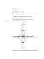
Front View . . . . . . . . . . . . . . . . . . . . . . . . . . . . . . . . . . . . . . . . . . . . . . . . . . . . . . . . . . . . 2-7
Rear View . . . . . . . . . . . . . . . . . . . . . . . . . . . . . . . . . . . . . . . . . . . . . . . . . . . . . . . . . . . 2-10
. . . . . . . . . . . . . . . . . . . . . . . . . . . . . . . . . . . . . . . . . . . . . . . . . . . . . . . . . . . . . . . . 2-11
. . . . . . . . . . . . . . . . . . . . . . . . . . . . . . . . . . . . . . . . . . . . . . . . . . . . . . . . . . . . . . . . 2-12
. . . . . . . . . . . . . . . . . . . . . . . . . . . . . . . . . . . . . . . . . . . . . . . . . . . . . . . . . . . . . . . . 2-13
. . . . . . . . . . . . . . . . . . . . . . . . . . . . . . . . . . . . . . . . . . . . . . . . . . . . . . . . . . . . . . . . 2-14
. . . . . . . . . . . . . . . . . . . . . . . . . . . . . . . . . . . . . . . . . . . . . . . . . . . . . . . . . . . . . . . . 2-15
Measurement Units . . . . . . . . . . . . . . . . . . . . . . . . . . . . . . . . . . . . . . . . . . . . . . . . . . . 2-16
GNDU - Ground Unit . . . . . . . . . . . . . . . . . . . . . . . . . . . . . . . . . . . . . . . . . . . . . . . . . 2-16
Agilent B1500 User’s Guide, Edition 7
Contents
About SMU . . . . . . . . . . . . . . . . . . . . . . . . . . . . . . . . . . . . . . . . . . . . . . . . . . . . . . . . 2-17
B1510A High Power SMU . . . . . . . . . . . . . . . . . . . . . . . . . . . . . . . . . . . . . . . . . . . . 2-18
B1511A Medium Power SMU . . . . . . . . . . . . . . . . . . . . . . . . . . . . . . . . . . . . . . . . . 2-21
B1517A High Resolution SMU . . . . . . . . . . . . . . . . . . . . . . . . . . . . . . . . . . . . . . . . . 2-24
B1520A Multi Frequency CMU. . . . . . . . . . . . . . . . . . . . . . . . . . . . . . . . . . . . . . . . . 2-28
B1525A High Voltage SPGU . . . . . . . . . . . . . . . . . . . . . . . . . . . . . . . . . . . . . . . . . . . 2-31
B1530A WGFMU . . . . . . . . . . . . . . . . . . . . . . . . . . . . . . . . . . . . . . . . . . . . . . . . . . . . 2-32
Specifications . . . . . . . . . . . . . . . . . . . . . . . . . . . . . . . . . . . . . . . . . . . . . . . . . . . . . . . . 2-33
Hardware . . . . . . . . . . . . . . . . . . . . . . . . . . . . . . . . . . . . . . . . . . . . . . . . . . . . . . . . . . 2-33
Agilent EasyEXPERT Software . . . . . . . . . . . . . . . . . . . . . . . . . . . . . . . . . . . . . . . . . 2-65
Agilent Desktop EasyEXPERT Software . . . . . . . . . . . . . . . . . . . . . . . . . . . . . . . . . 2-72
General Specifications . . . . . . . . . . . . . . . . . . . . . . . . . . . . . . . . . . . . . . . . . . . . . . . 2-75
Accessories and Options . . . . . . . . . . . . . . . . . . . . . . . . . . . . . . . . . . . . . . . . . . . . . . . 2-76
3. Installation
. . . . . . . . . . . . . . . . . . . . . . . . . . . . . . . . . . . . . . . . . . . . . . . . . . . . . . . . . . . . . . . . . 3-2
Requirements . . . . . . . . . . . . . . . . . . . . . . . . . . . . . . . . . . . . . . . . . . . . . . . . . . . . . . . . . 3-3
Power Requirements . . . . . . . . . . . . . . . . . . . . . . . . . . . . . . . . . . . . . . . . . . . . . . . . . 3-3
Operating Environment . . . . . . . . . . . . . . . . . . . . . . . . . . . . . . . . . . . . . . . . . . . . . . . 3-3
Storaging/Shipping Environment . . . . . . . . . . . . . . . . . . . . . . . . . . . . . . . . . . . . . . . 3-3
Ventilation Requirements . . . . . . . . . . . . . . . . . . . . . . . . . . . . . . . . . . . . . . . . . . . . . 3-4
Power Cable . . . . . . . . . . . . . . . . . . . . . . . . . . . . . . . . . . . . . . . . . . . . . . . . . . . . . . . . 3-4
Inspection and Installation. . . . . . . . . . . . . . . . . . . . . . . . . . . . . . . . . . . . . . . . . . . . . . . 3-6
To Inspect B1500 and Accessories . . . . . . . . . . . . . . . . . . . . . . . . . . . . . . . . . . . . . . 3-6
To Perform Initial Setup . . . . . . . . . . . . . . . . . . . . . . . . . . . . . . . . . . . . . . . . . . . . . . . 3-7
To Change Windows Logon Setting. . . . . . . . . . . . . . . . . . . . . . . . . . . . . . . . . . . . . . 3-9
To Change GPIB Address . . . . . . . . . . . . . . . . . . . . . . . . . . . . . . . . . . . . . . . . . . . . . . 3-9
To Enable System Controller . . . . . . . . . . . . . . . . . . . . . . . . . . . . . . . . . . . . . . . . . . 3-10
Installing Accessories . . . . . . . . . . . . . . . . . . . . . . . . . . . . . . . . . . . . . . . . . . . . . . . . . 3-11
Agilent B1500 User’s Guide, Edition 7
Contents
To Connect 16442B Test Fixture. . . . . . . . . . . . . . . . . . . . . . . . . . . . . . . . . . . . . . . . 3-12
To Connect Connector Plate . . . . . . . . . . . . . . . . . . . . . . . . . . . . . . . . . . . . . . . . . . 3-14
Connecting the interlock terminal . . . . . . . . . . . . . . . . . . . . . . . . . . . . . . . . . 3-16
To Connect ASU . . . . . . . . . . . . . . . . . . . . . . . . . . . . . . . . . . . . . . . . . . . . . . . . . . . . 3-17
To Connect SCUU/GSWU. . . . . . . . . . . . . . . . . . . . . . . . . . . . . . . . . . . . . . . . . . . . . 3-21
To Connect GNDU Adapter. . . . . . . . . . . . . . . . . . . . . . . . . . . . . . . . . . . . . . . . . . . . 3-25
To Interconnect SPGUs. . . . . . . . . . . . . . . . . . . . . . . . . . . . . . . . . . . . . . . . . . . . . . . 3-26
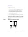
Mounting Connectors . . . . . . . . . . . . . . . . . . . . . . . . . . . . . . . . . . . . . . . . . . . . . . . . . 3-27
To Make an Interlock Circuit . . . . . . . . . . . . . . . . . . . . . . . . . . . . . . . . . . . . . . 3-29
To Connect GNDU Output . . . . . . . . . . . . . . . . . . . . . . . . . . . . . . . . . . . . . . . . . . . . 3-32
To Connect SMU Output . . . . . . . . . . . . . . . . . . . . . . . . . . . . . . . . . . . . . . . . . . . . . 3-33
To Connect MFCMU Output . . . . . . . . . . . . . . . . . . . . . . . . . . . . . . . . . . . . . . . . . . . 3-39
Connecting Measurement Devices . . . . . . . . . . . . . . . . . . . . . . . . . . . . . . . . . . . . . . . 3-40
Using Test Fixture . . . . . . . . . . . . . . . . . . . . . . . . . . . . . . . . . . . . . . . . . . . . . . . . . . . 3-41
Using Connector Plate . . . . . . . . . . . . . . . . . . . . . . . . . . . . . . . . . . . . . . . . . . . . . . . 3-43
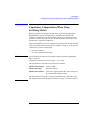
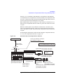
Capacitance Compensation When Using Switching Matrix . . . . . . . . . . . . . . . . . . . 3-47
Required Conditions . . . . . . . . . . . . . . . . . . . . . . . . . . . . . . . . . . . . . . . . . . . . . . . . . 3-48
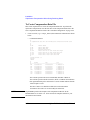
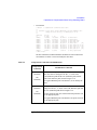
To Create Compensation Data File. . . . . . . . . . . . . . . . . . . . . . . . . . . . . . . . . . . . . . 3-50
Maintenance . . . . . . . . . . . . . . . . . . . . . . . . . . . . . . . . . . . . . . . . . . . . . . . . . . . . . . . . . 3-55
Cleaning . . . . . . . . . . . . . . . . . . . . . . . . . . . . . . . . . . . . . . . . . . . . . . . . . . . . . . . . . . 3-55
Self-test and Diagnostics . . . . . . . . . . . . . . . . . . . . . . . . . . . . . . . . . . . . . . . . . . . . . 3-55
Calibration . . . . . . . . . . . . . . . . . . . . . . . . . . . . . . . . . . . . . . . . . . . . . . . . . . . . . . . . . 3-55
About Plug-in Modules . . . . . . . . . . . . . . . . . . . . . . . . . . . . . . . . . . . . . . . . . . . . . . . . 3-56
Module Type and Locations . . . . . . . . . . . . . . . . . . . . . . . . . . . . . . . . . . . . . . . . . . . 3-57
4. Using EasyEXPERT
Start EasyEXPERT. . . . . . . . . . . . . . . . . . . . . . . . . . . . . . . . . . . . . . . . . . . . . . . . . . . . . . 4-4
Workspace Configurator . . . . . . . . . . . . . . . . . . . . . . . . . . . . . . . . . . . . . . . . . . . . . . . . 4-5
If there is no workspace. . . . . . . . . . . . . . . . . . . . . . . . . . . . . . . . . . . . . . . . . . . . . . . 4-5
Agilent B1500 User’s Guide, Edition 7
Contents
If there is one workspace . . . . . . . . . . . . . . . . . . . . . . . . . . . . . . . . . . . . . . . . . . . . . . 4-6
If there are Workspace more than two . . . . . . . . . . . . . . . . . . . . . . . . . . . . . . . . . . . 4-8
Main Screen . . . . . . . . . . . . . . . . . . . . . . . . . . . . . . . . . . . . . . . . . . . . . . . . . . . . . . . . . 4-10
Main Screen GUI . . . . . . . . . . . . . . . . . . . . . . . . . . . . . . . . . . . . . . . . . . . . . . . . . . . . 4-11
Run Option. . . . . . . . . . . . . . . . . . . . . . . . . . . . . . . . . . . . . . . . . . . . . . . . . . . . . . . . . 4-18
Data Display Manager . . . . . . . . . . . . . . . . . . . . . . . . . . . . . . . . . . . . . . . . . . . . . . . 4-19
Data Display Properties . . . . . . . . . . . . . . . . . . . . . . . . . . . . . . . . . . . . . . . . . . . . . . 4-20
Test Result Editor . . . . . . . . . . . . . . . . . . . . . . . . . . . . . . . . . . . . . . . . . . . . . . . . . . . 4-21
Test Results Data Filter. . . . . . . . . . . . . . . . . . . . . . . . . . . . . . . . . . . . . . . . . . . . . . . 4-22
Export in My Format . . . . . . . . . . . . . . . . . . . . . . . . . . . . . . . . . . . . . . . . . . . . . . . . . 4-22
Test Results Data Folder Export . . . . . . . . . . . . . . . . . . . . . . . . . . . . . . . . . . . . . . . . 4-23
Test Results Data Auto Export . . . . . . . . . . . . . . . . . . . . . . . . . . . . . . . . . . . . . . . . . 4-24
Test Results Data Properties . . . . . . . . . . . . . . . . . . . . . . . . . . . . . . . . . . . . . . . . . . 4-26
Application Test. . . . . . . . . . . . . . . . . . . . . . . . . . . . . . . . . . . . . . . . . . . . . . . . . . . . . . . 4-27
Quick Test . . . . . . . . . . . . . . . . . . . . . . . . . . . . . . . . . . . . . . . . . . . . . . . . . . . . . . . . . . . 4-29
Repeat Measurement Setup . . . . . . . . . . . . . . . . . . . . . . . . . . . . . . . . . . . . . . . . . . . . 4-31
Organize Preset Group . . . . . . . . . . . . . . . . . . . . . . . . . . . . . . . . . . . . . . . . . . . . . . . . . 4-33
Calibration . . . . . . . . . . . . . . . . . . . . . . . . . . . . . . . . . . . . . . . . . . . . . . . . . . . . . . . . . . . 4-35
Module Self Calibration . . . . . . . . . . . . . . . . . . . . . . . . . . . . . . . . . . . . . . . . . . . . . . 4-35
SMU Zero Cancel . . . . . . . . . . . . . . . . . . . . . . . . . . . . . . . . . . . . . . . . . . . . . . . . . . . 4-36
CMU Calibration . . . . . . . . . . . . . . . . . . . . . . . . . . . . . . . . . . . . . . . . . . . . . . . . . . . . 4-37
Configuration. . . . . . . . . . . . . . . . . . . . . . . . . . . . . . . . . . . . . . . . . . . . . . . . . . . . . . . . . 4-41
Main Frame . . . . . . . . . . . . . . . . . . . . . . . . . . . . . . . . . . . . . . . . . . . . . . . . . . . . . . . . 4-41
Modules. . . . . . . . . . . . . . . . . . . . . . . . . . . . . . . . . . . . . . . . . . . . . . . . . . . . . . . . . . . 4-42
ASU . . . . . . . . . . . . . . . . . . . . . . . . . . . . . . . . . . . . . . . . . . . . . . . . . . . . . . . . . . . . . . 4-43
Switching Matrix . . . . . . . . . . . . . . . . . . . . . . . . . . . . . . . . . . . . . . . . . . . . . . . . . . . . 4-43
SMU/PG Selector . . . . . . . . . . . . . . . . . . . . . . . . . . . . . . . . . . . . . . . . . . . . . . . . . . . 4-45
Event Log . . . . . . . . . . . . . . . . . . . . . . . . . . . . . . . . . . . . . . . . . . . . . . . . . . . . . . . . . . 4-45
Extended Configuration . . . . . . . . . . . . . . . . . . . . . . . . . . . . . . . . . . . . . . . . . . . . . . 4-46
Agilent B1500 User’s Guide, Edition 7
Contents
Switching Matrix Operation Panel. . . . . . . . . . . . . . . . . . . . . . . . . . . . . . . . . . . . . . . . 4-48
Standby Channel Definition . . . . . . . . . . . . . . . . . . . . . . . . . . . . . . . . . . . . . . . . . . . . . 4-50
Data Display . . . . . . . . . . . . . . . . . . . . . . . . . . . . . . . . . . . . . . . . . . . . . . . . . . . . . . . . . 4-51
Data Display GUI. . . . . . . . . . . . . . . . . . . . . . . . . . . . . . . . . . . . . . . . . . . . . . . . . . . . 4-53
Display Setup . . . . . . . . . . . . . . . . . . . . . . . . . . . . . . . . . . . . . . . . . . . . . . . . . . . . . . 4-62
Graph Properties . . . . . . . . . . . . . . . . . . . . . . . . . . . . . . . . . . . . . . . . . . . . . . . . . . . . 4-63
List Display Properties . . . . . . . . . . . . . . . . . . . . . . . . . . . . . . . . . . . . . . . . . . . . . . . 4-64
Tool Bar . . . . . . . . . . . . . . . . . . . . . . . . . . . . . . . . . . . . . . . . . . . . . . . . . . . . . . . . . . . 4-64
Data Status . . . . . . . . . . . . . . . . . . . . . . . . . . . . . . . . . . . . . . . . . . . . . . . . . . . . . . . . 4-67
Miscellaneous Operations . . . . . . . . . . . . . . . . . . . . . . . . . . . . . . . . . . . . . . . . . . . . 4-68
Preview . . . . . . . . . . . . . . . . . . . . . . . . . . . . . . . . . . . . . . . . . . . . . . . . . . . . . . . . . . . . . 4-74
Preview Window GUI . . . . . . . . . . . . . . . . . . . . . . . . . . . . . . . . . . . . . . . . . . . . . . . . 4-74
Preview Settings . . . . . . . . . . . . . . . . . . . . . . . . . . . . . . . . . . . . . . . . . . . . . . . . . . . . 4-76
Text File Export settings . . . . . . . . . . . . . . . . . . . . . . . . . . . . . . . . . . . . . . . . . . . . . . . . 4-77
5. Classic Test Definition
I/V Sweep . . . . . . . . . . . . . . . . . . . . . . . . . . . . . . . . . . . . . . . . . . . . . . . . . . . . . . . . . . . . 5-4
Channel Setup. . . . . . . . . . . . . . . . . . . . . . . . . . . . . . . . . . . . . . . . . . . . . . . . . . . . . . . 5-5
Measurement Setup . . . . . . . . . . . . . . . . . . . . . . . . . . . . . . . . . . . . . . . . . . . . . . . . . . 5-6
Multi Channel I/V Sweep . . . . . . . . . . . . . . . . . . . . . . . . . . . . . . . . . . . . . . . . . . . . . . . 5-9
Channel Setup. . . . . . . . . . . . . . . . . . . . . . . . . . . . . . . . . . . . . . . . . . . . . . . . . . . . . . 5-10
Measurement Setup . . . . . . . . . . . . . . . . . . . . . . . . . . . . . . . . . . . . . . . . . . . . . . . . . 5-11
I/V List Sweep . . . . . . . . . . . . . . . . . . . . . . . . . . . . . . . . . . . . . . . . . . . . . . . . . . . . . . . 5-13
Channel Setup. . . . . . . . . . . . . . . . . . . . . . . . . . . . . . . . . . . . . . . . . . . . . . . . . . . . . . 5-14
Measurement Setup . . . . . . . . . . . . . . . . . . . . . . . . . . . . . . . . . . . . . . . . . . . . . . . . . 5-15
Define vector data. . . . . . . . . . . . . . . . . . . . . . . . . . . . . . . . . . . . . . . . . . . . . . . . . . . 5-18
I/V-t Sampling. . . . . . . . . . . . . . . . . . . . . . . . . . . . . . . . . . . . . . . . . . . . . . . . . . . . . . . . 5-21
Channel Setup. . . . . . . . . . . . . . . . . . . . . . . . . . . . . . . . . . . . . . . . . . . . . . . . . . . . . . 5-22
Measurement Setup . . . . . . . . . . . . . . . . . . . . . . . . . . . . . . . . . . . . . . . . . . . . . . . . . 5-23
Agilent B1500 User’s Guide, Edition 7
Contents
C-V Sweep . . . . . . . . . . . . . . . . . . . . . . . . . . . . . . . . . . . . . . . . . . . . . . . . . . . . . . . . . . . 5-26
Channel Setup . . . . . . . . . . . . . . . . . . . . . . . . . . . . . . . . . . . . . . . . . . . . . . . . . . . . . . 5-27
Measurement Setup . . . . . . . . . . . . . . . . . . . . . . . . . . . . . . . . . . . . . . . . . . . . . . . . . 5-28
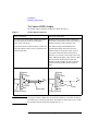
Direct Control . . . . . . . . . . . . . . . . . . . . . . . . . . . . . . . . . . . . . . . . . . . . . . . . . . . . . . . . 5-30
Channel Setup . . . . . . . . . . . . . . . . . . . . . . . . . . . . . . . . . . . . . . . . . . . . . . . . . . . . . . 5-31
Measurement Setup . . . . . . . . . . . . . . . . . . . . . . . . . . . . . . . . . . . . . . . . . . . . . . . . . 5-33
Advanced Setup . . . . . . . . . . . . . . . . . . . . . . . . . . . . . . . . . . . . . . . . . . . . . . . . . . . . 5-34
Command Setup . . . . . . . . . . . . . . . . . . . . . . . . . . . . . . . . . . . . . . . . . . . . . . . . . . . . 5-36
compenReZ . . . . . . . . . . . . . . . . . . . . . . . . . . . . . . . . . . . . . . . . . . . . . . . . . . . . . . . . 5-38
compenImZ . . . . . . . . . . . . . . . . . . . . . . . . . . . . . . . . . . . . . . . . . . . . . . . . . . . . . . . . 5-39
compenReY . . . . . . . . . . . . . . . . . . . . . . . . . . . . . . . . . . . . . . . . . . . . . . . . . . . . . . . . 5-40
compenImY . . . . . . . . . . . . . . . . . . . . . . . . . . . . . . . . . . . . . . . . . . . . . . . . . . . . . . . . 5-41
Function Setup . . . . . . . . . . . . . . . . . . . . . . . . . . . . . . . . . . . . . . . . . . . . . . . . . . . . . . . 5-42
Auto Analysis Setup . . . . . . . . . . . . . . . . . . . . . . . . . . . . . . . . . . . . . . . . . . . . . . . . . . . 5-43
Display Setup . . . . . . . . . . . . . . . . . . . . . . . . . . . . . . . . . . . . . . . . . . . . . . . . . . . . . . . . 5-46
SMU Range Setup Window . . . . . . . . . . . . . . . . . . . . . . . . . . . . . . . . . . . . . . . . . . . . . 5-48
ADC and Integration Time Setup Window . . . . . . . . . . . . . . . . . . . . . . . . . . . . . . . . . 5-50
Advanced Setup Window . . . . . . . . . . . . . . . . . . . . . . . . . . . . . . . . . . . . . . . . . . . . . . . 5-51
CMU Range Setup Window . . . . . . . . . . . . . . . . . . . . . . . . . . . . . . . . . . . . . . . . . . . . . 5-53
Advanced Setup Window for C-V Sweep . . . . . . . . . . . . . . . . . . . . . . . . . . . . . . . . . . 5-54
Switching Matrix Control . . . . . . . . . . . . . . . . . . . . . . . . . . . . . . . . . . . . . . . . . . . . . . . 5-55
SPGU Control. . . . . . . . . . . . . . . . . . . . . . . . . . . . . . . . . . . . . . . . . . . . . . . . . . . . . . . . . 5-57
Advanced Setup Window for SPGU Control . . . . . . . . . . . . . . . . . . . . . . . . . . . . . . 5-58
SPGU Pulse Setup Window . . . . . . . . . . . . . . . . . . . . . . . . . . . . . . . . . . . . . . . . . . . . . 5-59
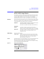
Load Z Setup Window . . . . . . . . . . . . . . . . . . . . . . . . . . . . . . . . . . . . . . . . . . . . . . . . . 5-61
Pulse Switch Setup Window . . . . . . . . . . . . . . . . . . . . . . . . . . . . . . . . . . . . . . . . . . . . 5-62
Agilent B1500 User’s Guide, Edition 7
Contents
SPGU ALWG Setup Window . . . . . . . . . . . . . . . . . . . . . . . . . . . . . . . . . . . . . . . . . . . . 5-63
Define ALWG Waveform Window . . . . . . . . . . . . . . . . . . . . . . . . . . . . . . . . . . . . . . . . 5-64
Waveform Pattern Editor . . . . . . . . . . . . . . . . . . . . . . . . . . . . . . . . . . . . . . . . . . . . . 5-67
6. Application Test Definition
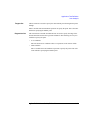
Test Definition Window . . . . . . . . . . . . . . . . . . . . . . . . . . . . . . . . . . . . . . . . . . . . . . . . . 6-3
Test Specification . . . . . . . . . . . . . . . . . . . . . . . . . . . . . . . . . . . . . . . . . . . . . . . . . . . . . . 6-5
Define Layout . . . . . . . . . . . . . . . . . . . . . . . . . . . . . . . . . . . . . . . . . . . . . . . . . . . . . . 6-10
Test Output . . . . . . . . . . . . . . . . . . . . . . . . . . . . . . . . . . . . . . . . . . . . . . . . . . . . . . . . . . 6-14
Analysis Parameter Definition . . . . . . . . . . . . . . . . . . . . . . . . . . . . . . . . . . . . . . . . . 6-15
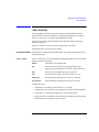
Test Contents . . . . . . . . . . . . . . . . . . . . . . . . . . . . . . . . . . . . . . . . . . . . . . . . . . . . . . . . 6-16
Defining/Editing Test Contents . . . . . . . . . . . . . . . . . . . . . . . . . . . . . . . . . . . . . . . . 6-17
Debugging Test Contents . . . . . . . . . . . . . . . . . . . . . . . . . . . . . . . . . . . . . . . . . . . . . 6-21
Variable Inspector . . . . . . . . . . . . . . . . . . . . . . . . . . . . . . . . . . . . . . . . . . . . . . . . . . . 6-22
External Variable Setup . . . . . . . . . . . . . . . . . . . . . . . . . . . . . . . . . . . . . . . . . . . . . . 6-23
Local Variable Definition . . . . . . . . . . . . . . . . . . . . . . . . . . . . . . . . . . . . . . . . . . . . . . . 6-24
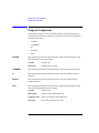
Program Component. . . . . . . . . . . . . . . . . . . . . . . . . . . . . . . . . . . . . . . . . . . . . . . . . . . 6-26
Auto Analysis . . . . . . . . . . . . . . . . . . . . . . . . . . . . . . . . . . . . . . . . . . . . . . . . . . . . . . . . 6-27
Data Display Control. . . . . . . . . . . . . . . . . . . . . . . . . . . . . . . . . . . . . . . . . . . . . . . . . . . 6-30
Display Data Setup . . . . . . . . . . . . . . . . . . . . . . . . . . . . . . . . . . . . . . . . . . . . . . . . . . . . 6-31
GPIB I/O . . . . . . . . . . . . . . . . . . . . . . . . . . . . . . . . . . . . . . . . . . . . . . . . . . . . . . . . . . . . 6-33
Message . . . . . . . . . . . . . . . . . . . . . . . . . . . . . . . . . . . . . . . . . . . . . . . . . . . . . . . . . . . . 6-38
Data Store Control . . . . . . . . . . . . . . . . . . . . . . . . . . . . . . . . . . . . . . . . . . . . . . . . . . . . 6-39
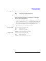
Command Execution. . . . . . . . . . . . . . . . . . . . . . . . . . . . . . . . . . . . . . . . . . . . . . . . . . . 6-40
Using Command Execution . . . . . . . . . . . . . . . . . . . . . . . . . . . . . . . . . . . . . . . . . . . . . 6-42
Command Parameters . . . . . . . . . . . . . . . . . . . . . . . . . . . . . . . . . . . . . . . . . . . . . . . 6-42
Agilent B1500 User’s Guide, Edition 7
Contents
Defining Numeric/Vector Input Parameter . . . . . . . . . . . . . . . . . . . . . . . . . . . . . . . 6-43
Defining String/Numeric Input Parameters . . . . . . . . . . . . . . . . . . . . . . . . . . . . . . 6-43
Defining Numeric Output Parameter . . . . . . . . . . . . . . . . . . . . . . . . . . . . . . . . . . . . 6-44
Defining Vector Output Parameter. . . . . . . . . . . . . . . . . . . . . . . . . . . . . . . . . . . . . . 6-44
Defining String Output Parameter . . . . . . . . . . . . . . . . . . . . . . . . . . . . . . . . . . . . . . 6-44
Defining Format Field . . . . . . . . . . . . . . . . . . . . . . . . . . . . . . . . . . . . . . . . . . . . . . . . 6-45
Setup Example. . . . . . . . . . . . . . . . . . . . . . . . . . . . . . . . . . . . . . . . . . . . . . . . . . . . . . 6-46
7. Function Details
I/V Sweep Measurement. . . . . . . . . . . . . . . . . . . . . . . . . . . . . . . . . . . . . . . . . . . . . . . . 7-3
Available Modules. . . . . . . . . . . . . . . . . . . . . . . . . . . . . . . . . . . . . . . . . . . . . . . . . . . . 7-3
Output Range . . . . . . . . . . . . . . . . . . . . . . . . . . . . . . . . . . . . . . . . . . . . . . . . . . . . . . . 7-4
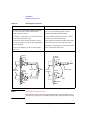
Basic Sweep Measurement . . . . . . . . . . . . . . . . . . . . . . . . . . . . . . . . . . . . . . . . . . . 7-4
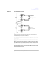
Subordinate Sweep Measurement . . . . . . . . . . . . . . . . . . . . . . . . . . . . . . . . . . . . . . 7-6
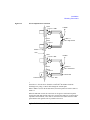
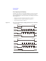
Synchronous Sweep Measurement . . . . . . . . . . . . . . . . . . . . . . . . . . . . . . . . . . . . . 7-8
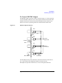
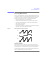
Pulsed Sweep Measurement . . . . . . . . . . . . . . . . . . . . . . . . . . . . . . . . . . . . . . . . . . 7-9
Multi Channel I/V Sweep Measurement . . . . . . . . . . . . . . . . . . . . . . . . . . . . . . . . . . 7-12
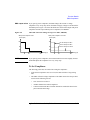
I/V-t Sampling Measurement . . . . . . . . . . . . . . . . . . . . . . . . . . . . . . . . . . . . . . . . . . . 7-13
Available Modules. . . . . . . . . . . . . . . . . . . . . . . . . . . . . . . . . . . . . . . . . . . . . . . . . . . 7-13
Operation Summary . . . . . . . . . . . . . . . . . . . . . . . . . . . . . . . . . . . . . . . . . . . . . . . . . 7-13
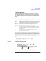
Setup Parameters . . . . . . . . . . . . . . . . . . . . . . . . . . . . . . . . . . . . . . . . . . . . . . . . . . . 7-15
Time Data and Index . . . . . . . . . . . . . . . . . . . . . . . . . . . . . . . . . . . . . . . . . . . . . . . . . 7-17
Source Output Sequence and Time Origin . . . . . . . . . . . . . . . . . . . . . . . . . . . . . . . 7-18
Sampling Completion . . . . . . . . . . . . . . . . . . . . . . . . . . . . . . . . . . . . . . . . . . . . . . . . 7-18
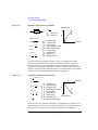
C-V Sweep Measurement. . . . . . . . . . . . . . . . . . . . . . . . . . . . . . . . . . . . . . . . . . . . . . . 7-19
Available Module . . . . . . . . . . . . . . . . . . . . . . . . . . . . . . . . . . . . . . . . . . . . . . . . . . . 7-19
Setup Parameters . . . . . . . . . . . . . . . . . . . . . . . . . . . . . . . . . . . . . . . . . . . . . . . . . . . 7-19
Measurement Parameters . . . . . . . . . . . . . . . . . . . . . . . . . . . . . . . . . . . . . . . . . . . . 7-21
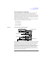
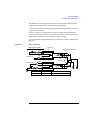
Four-Terminal Pair Configuration . . . . . . . . . . . . . . . . . . . . . . . . . . . . . . . . . . . . . . . 7-23
Error Correction . . . . . . . . . . . . . . . . . . . . . . . . . . . . . . . . . . . . . . . . . . . . . . . . . . . . . 7-24
Agilent B1500 User’s Guide, Edition 7
Contents
SPGU Module . . . . . . . . . . . . . . . . . . . . . . . . . . . . . . . . . . . . . . . . . . . . . . . . . . . . . . . . 7-26
PG Operation Mode . . . . . . . . . . . . . . . . . . . . . . . . . . . . . . . . . . . . . . . . . . . . . . . . . 7-27
ALWG Operation Mode . . . . . . . . . . . . . . . . . . . . . . . . . . . . . . . . . . . . . . . . . . . . . . 7-34
Sweep Abort Function . . . . . . . . . . . . . . . . . . . . . . . . . . . . . . . . . . . . . . . . . . . . . . . . . 7-36
When abort occurs . . . . . . . . . . . . . . . . . . . . . . . . . . . . . . . . . . . . . . . . . . . . . . . . . . 7-36
Standby Function . . . . . . . . . . . . . . . . . . . . . . . . . . . . . . . . . . . . . . . . . . . . . . . . . . . . . 7-37
Standby Channels . . . . . . . . . . . . . . . . . . . . . . . . . . . . . . . . . . . . . . . . . . . . . . . . . . . 7-37
Standby State . . . . . . . . . . . . . . . . . . . . . . . . . . . . . . . . . . . . . . . . . . . . . . . . . . . . . . 7-37
Output Sequence of Standby Channels. . . . . . . . . . . . . . . . . . . . . . . . . . . . . . . . . . 7-38
To Use Standby Function . . . . . . . . . . . . . . . . . . . . . . . . . . . . . . . . . . . . . . . . . . . . . 7-39
Bias Hold Function . . . . . . . . . . . . . . . . . . . . . . . . . . . . . . . . . . . . . . . . . . . . . . . . . . . . 7-40
Current Offset Cancel . . . . . . . . . . . . . . . . . . . . . . . . . . . . . . . . . . . . . . . . . . . . . . . . . . 7-42
SMU CMU Unify Unit . . . . . . . . . . . . . . . . . . . . . . . . . . . . . . . . . . . . . . . . . . . . . . . . . . 7-44
Atto Sense and Switch Unit. . . . . . . . . . . . . . . . . . . . . . . . . . . . . . . . . . . . . . . . . . . . . 7-46
SMU/PG Selector . . . . . . . . . . . . . . . . . . . . . . . . . . . . . . . . . . . . . . . . . . . . . . . . . . . . . 7-48
SMU Ranging Mode . . . . . . . . . . . . . . . . . . . . . . . . . . . . . . . . . . . . . . . . . . . . . . . . . . . 7-49
To Set Ranging Mode . . . . . . . . . . . . . . . . . . . . . . . . . . . . . . . . . . . . . . . . . . . . . . . . 7-49
Auto Ranging . . . . . . . . . . . . . . . . . . . . . . . . . . . . . . . . . . . . . . . . . . . . . . . . . . . . . . 7-50
Limited Auto Ranging . . . . . . . . . . . . . . . . . . . . . . . . . . . . . . . . . . . . . . . . . . . . . . . . 7-51
Fixed Range. . . . . . . . . . . . . . . . . . . . . . . . . . . . . . . . . . . . . . . . . . . . . . . . . . . . . . . . 7-51
Compliance Range . . . . . . . . . . . . . . . . . . . . . . . . . . . . . . . . . . . . . . . . . . . . . . . . . . 7-51
Enhanced Auto Ranging for Current Measurement . . . . . . . . . . . . . . . . . . . . . . . . 7-52
SMU Compliance . . . . . . . . . . . . . . . . . . . . . . . . . . . . . . . . . . . . . . . . . . . . . . . . . . . . . 7-53
Polarity and Output Area . . . . . . . . . . . . . . . . . . . . . . . . . . . . . . . . . . . . . . . . . . . . . 7-53
Power Compliance . . . . . . . . . . . . . . . . . . . . . . . . . . . . . . . . . . . . . . . . . . . . . . . . . . 7-54
To Set Compliance . . . . . . . . . . . . . . . . . . . . . . . . . . . . . . . . . . . . . . . . . . . . . . . . . . 7-55
SMU Pulse . . . . . . . . . . . . . . . . . . . . . . . . . . . . . . . . . . . . . . . . . . . . . . . . . . . . . . . . . . 7-56
To Set Pulse Output . . . . . . . . . . . . . . . . . . . . . . . . . . . . . . . . . . . . . . . . . . . . . . . . . 7-56
Agilent B1500 User’s Guide, Edition 7
Contents
SMU Measurement Time . . . . . . . . . . . . . . . . . . . . . . . . . . . . . . . . . . . . . . . . . . . . . . 7-57
Integration Time . . . . . . . . . . . . . . . . . . . . . . . . . . . . . . . . . . . . . . . . . . . . . . . . . . . . 7-57
Overhead Time . . . . . . . . . . . . . . . . . . . . . . . . . . . . . . . . . . . . . . . . . . . . . . . . . . . . . 7-59
To Specify Source Output Time . . . . . . . . . . . . . . . . . . . . . . . . . . . . . . . . . . . . . . . . 7-59
Wait Time . . . . . . . . . . . . . . . . . . . . . . . . . . . . . . . . . . . . . . . . . . . . . . . . . . . . . . . . . 7-60
Multiple Measurement Channels. . . . . . . . . . . . . . . . . . . . . . . . . . . . . . . . . . . . . . . 7-61
SMU Filter . . . . . . . . . . . . . . . . . . . . . . . . . . . . . . . . . . . . . . . . . . . . . . . . . . . . . . . . . . . 7-62
SMU Series Resistor. . . . . . . . . . . . . . . . . . . . . . . . . . . . . . . . . . . . . . . . . . . . . . . . . . . 7-63
Interlock Function . . . . . . . . . . . . . . . . . . . . . . . . . . . . . . . . . . . . . . . . . . . . . . . . . . . . . 7-64
Auto Power Off Function . . . . . . . . . . . . . . . . . . . . . . . . . . . . . . . . . . . . . . . . . . . . . . . 7-65
Initial Settings . . . . . . . . . . . . . . . . . . . . . . . . . . . . . . . . . . . . . . . . . . . . . . . . . . . . . . . 7-66
8. Built-in Programming Tool
Variables and Expressions . . . . . . . . . . . . . . . . . . . . . . . . . . . . . . . . . . . . . . . . . . . . . . . 8-3
Expressions . . . . . . . . . . . . . . . . . . . . . . . . . . . . . . . . . . . . . . . . . . . . . . . . . . . . . . . . . 8-4
Built-in Functions . . . . . . . . . . . . . . . . . . . . . . . . . . . . . . . . . . . . . . . . . . . . . . . . . . . . . . 8-7
Read Out Functions . . . . . . . . . . . . . . . . . . . . . . . . . . . . . . . . . . . . . . . . . . . . . . . . . . . 8-15
Functions for Marker . . . . . . . . . . . . . . . . . . . . . . . . . . . . . . . . . . . . . . . . . . . . . . . . 8-15
Functions for Cursor . . . . . . . . . . . . . . . . . . . . . . . . . . . . . . . . . . . . . . . . . . . . . . . . . 8-15
Functions for Line . . . . . . . . . . . . . . . . . . . . . . . . . . . . . . . . . . . . . . . . . . . . . . . . . . . 8-16
Functions for Two Line Display . . . . . . . . . . . . . . . . . . . . . . . . . . . . . . . . . . . . . . . . 8-17
Script Program Statements . . . . . . . . . . . . . . . . . . . . . . . . . . . . . . . . . . . . . . . . . . . . . 8-19
9. If You Have a Problem
When You Operate B1500A . . . . . . . . . . . . . . . . . . . . . . . . . . . . . . . . . . . . . . . . . . . . . . 9-3
Power On Trouble . . . . . . . . . . . . . . . . . . . . . . . . . . . . . . . . . . . . . . . . . . . . . . . . . . . . 9-3
SCUU is not Detected . . . . . . . . . . . . . . . . . . . . . . . . . . . . . . . . . . . . . . . . . . . . . . . . . 9-3
ASU is not Detected . . . . . . . . . . . . . . . . . . . . . . . . . . . . . . . . . . . . . . . . . . . . . . . . . . 9-4
Agilent B1500 User’s Guide, Edition 7
Contents
External GPIB Devices are not Detected. . . . . . . . . . . . . . . . . . . . . . . . . . . . . . . . . . 9-4
To Simplify the Connections. . . . . . . . . . . . . . . . . . . . . . . . . . . . . . . . . . . . . . . . . . . . 9-5
When You Perform Measurement . . . . . . . . . . . . . . . . . . . . . . . . . . . . . . . . . . . . . . . . . 9-6
Measurement Takes More Time than Specified . . . . . . . . . . . . . . . . . . . . . . . . . . . . 9-6
Noise Affects the Measured Values . . . . . . . . . . . . . . . . . . . . . . . . . . . . . . . . . . . . . 9-7
Voltage Measurement Error is Large. . . . . . . . . . . . . . . . . . . . . . . . . . . . . . . . . . . . . 9-8
SMU Oscillates for High-Frequency Device Measurements . . . . . . . . . . . . . . . . . . 9-8
SMU Oscillates for Negative Resistance Measurements . . . . . . . . . . . . . . . . . . . . 9-9
Large Current Causes High Temperature (Thermal Drift). . . . . . . . . . . . . . . . . . . . 9-10
Measurement Damages the Device under Test . . . . . . . . . . . . . . . . . . . . . . . . . . . 9-10
Leaving Connections Damages Devices after Measurement . . . . . . . . . . . . . . . . 9-10
Unexpected Sampling Measurement Data is Returned . . . . . . . . . . . . . . . . . . . . . 9-11
MFCMU Causes Unbalance Condition . . . . . . . . . . . . . . . . . . . . . . . . . . . . . . . . . . 9-11
Before Shipping to Service Center . . . . . . . . . . . . . . . . . . . . . . . . . . . . . . . . . . . . . . . 9-12
To Make Backup . . . . . . . . . . . . . . . . . . . . . . . . . . . . . . . . . . . . . . . . . . . . . . . . . . . . 9-12
To Check Module Slots. . . . . . . . . . . . . . . . . . . . . . . . . . . . . . . . . . . . . . . . . . . . . . . 9-12
To Check ASU/HRSMU Combination . . . . . . . . . . . . . . . . . . . . . . . . . . . . . . . . . . . 9-12
To Collect Equipment and Accessories . . . . . . . . . . . . . . . . . . . . . . . . . . . . . . . . . . 9-13
Data Backup and Recovery . . . . . . . . . . . . . . . . . . . . . . . . . . . . . . . . . . . . . . . . . . . . . 9-14
Folders to Backup . . . . . . . . . . . . . . . . . . . . . . . . . . . . . . . . . . . . . . . . . . . . . . . . . . . 9-15
To Make Database Backup. . . . . . . . . . . . . . . . . . . . . . . . . . . . . . . . . . . . . . . . . . . . 9-15
To Restore Database Backup . . . . . . . . . . . . . . . . . . . . . . . . . . . . . . . . . . . . . . . . . . 9-16
To Make Backup of Other Data . . . . . . . . . . . . . . . . . . . . . . . . . . . . . . . . . . . . . . . . 9-17
To Restore Backup of Other Data . . . . . . . . . . . . . . . . . . . . . . . . . . . . . . . . . . . . . . 9-18
B1500A System Recovery . . . . . . . . . . . . . . . . . . . . . . . . . . . . . . . . . . . . . . . . . . . . . . 9-19
To Perform System Recovery . . . . . . . . . . . . . . . . . . . . . . . . . . . . . . . . . . . . . . . . . . 9-19
To Initialize Database . . . . . . . . . . . . . . . . . . . . . . . . . . . . . . . . . . . . . . . . . . . . . . . . 9-20
To Restore Database. . . . . . . . . . . . . . . . . . . . . . . . . . . . . . . . . . . . . . . . . . . . . . . . . 9-21
Updating EasyEXPERT . . . . . . . . . . . . . . . . . . . . . . . . . . . . . . . . . . . . . . . . . . . . . . . . . 9-22
Agilent B1500 User’s Guide, Edition 7
Contents
Error Codes . . . . . . . . . . . . . . . . . . . . . . . . . . . . . . . . . . . . . . . . . . . . . . . . . . . . . . . . . . 9-23
Agilent EasyEXPERT Operation Error. . . . . . . . . . . . . . . . . . . . . . . . . . . . . . . . . . . . 9-23
Agilent FLEX Execution Error . . . . . . . . . . . . . . . . . . . . . . . . . . . . . . . . . . . . . . . . . . 9-48
Agilent B1500A Self-test/Calibration Error. . . . . . . . . . . . . . . . . . . . . . . . . . . . . . . 9-66
Setup File Converter Execution Error. . . . . . . . . . . . . . . . . . . . . . . . . . . . . . . . . . . . 9-77
10. Application Library and Utilities
Application Test Definitions . . . . . . . . . . . . . . . . . . . . . . . . . . . . . . . . . . . . . . . . . . . . . 10-3
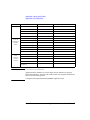
QSCV Measurement Supplemental Data . . . . . . . . . . . . . . . . . . . . . . . . . . . . . . . . . 10-13
Maximum Measurement Value . . . . . . . . . . . . . . . . . . . . . . . . . . . . . . . . . . . . . . . 10-13
Considering Measurement Accuracy. . . . . . . . . . . . . . . . . . . . . . . . . . . . . . . . . . . 10-17
License Management Tool . . . . . . . . . . . . . . . . . . . . . . . . . . . . . . . . . . . . . . . . . . . . . 10-49
License Management Tool GUI . . . . . . . . . . . . . . . . . . . . . . . . . . . . . . . . . . . . . . . 10-49
Setup File Converter . . . . . . . . . . . . . . . . . . . . . . . . . . . . . . . . . . . . . . . . . . . . . . . . . . 10-50
Setup File Converter GUI . . . . . . . . . . . . . . . . . . . . . . . . . . . . . . . . . . . . . . . . . . . . 10-51
Utility Programs. . . . . . . . . . . . . . . . . . . . . . . . . . . . . . . . . . . . . . . . . . . . . . . . . . . . . . 10-52
Prober Control . . . . . . . . . . . . . . . . . . . . . . . . . . . . . . . . . . . . . . . . . . . . . . . . . . . . . 10-52
SetupFileConverter.exe . . . . . . . . . . . . . . . . . . . . . . . . . . . . . . . . . . . . . . . . . . . . . . 10-53
sleep.exe . . . . . . . . . . . . . . . . . . . . . . . . . . . . . . . . . . . . . . . . . . . . . . . . . . . . . . . . . 10-56
XSLT . . . . . . . . . . . . . . . . . . . . . . . . . . . . . . . . . . . . . . . . . . . . . . . . . . . . . . . . . . . . . 10-57
Desktop EasyEXPERT . . . . . . . . . . . . . . . . . . . . . . . . . . . . . . . . . . . . . . . . . . . . . . . . . 10-67
About Desktop EasyEXPERT . . . . . . . . . . . . . . . . . . . . . . . . . . . . . . . . . . . . . . . . . 10-68
System Requirements. . . . . . . . . . . . . . . . . . . . . . . . . . . . . . . . . . . . . . . . . . . . . . . 10-69
To Install Desktop EasyEXPERT . . . . . . . . . . . . . . . . . . . . . . . . . . . . . . . . . . . . . . . 10-70
Before Starting Desktop EasyEXPERT . . . . . . . . . . . . . . . . . . . . . . . . . . . . . . . . . . 10-70
To Start Desktop EasyEXPERT . . . . . . . . . . . . . . . . . . . . . . . . . . . . . . . . . . . . . . . . 10-71
Execution Mode dialog box . . . . . . . . . . . . . . . . . . . . . . . . . . . . . . . . . . . . . . . . . . 10-71
Start EasyEXPERT window. . . . . . . . . . . . . . . . . . . . . . . . . . . . . . . . . . . . . . . . . . . 10-72
To Change Execution Mode and GPIB Settings . . . . . . . . . . . . . . . . . . . . . . . . . . 10-73
Agilent B1500 User’s Guide, Edition 7
Contents
To Move the EasyEXPERT Database . . . . . . . . . . . . . . . . . . . . . . . . . . . . . . . . . . . 10-73
Using 4155B/4156B/4155C/4156C. . . . . . . . . . . . . . . . . . . . . . . . . . . . . . . . . . . . 10-74
Agilent B1500 User’s Guide, Edition 7
Contents
Agilent B1500 User’s Guide, Edition 7
1
Getting Started
Getting Started
This chapter describes the basic operations of Agilent B1500A. Before learning the
product details, let’s try to use the B1500A briefly. The operations need the
B1500A, power cable, and USB keyboard only (USB mouse and stylus pen are
optional).
During the operations, you will not connect device under test. Open all
measurement terminal.
This chapter consists of the following sections.
•
“To Turn On/Off B1500A”
•
“To Launch EasyEXPERT”
•
“To Use Application Test Mode”
•
“To Use Classic Test Mode”
•
“To Perform Measurement”
•
“To Use Analysis Tools”
1-2
Agilent B1500 User’s Guide, Edition 7
Getting Started
To Turn On/Off B1500A
To Turn On/Off B1500A
NOTE
When turning the B1500A on
Open the measurement terminals at the device side when turning the B1500A on.
Also disconnect the device from the measurement terminals and open the
measurement terminals after the test. If you leave the connection with the device,
the device may be damaged by unexpected operations or charge-up of measurement
cables.
NOTE
If you use the B1500A at the first time
If this is the first time to turn Agilent B1500 on after the delivery, you need to
perform the initial setup of the B1500. See “Inspection and Installation” on page
3-6. After the initial setup and if no users are added, you can automatically logon as
“Agilent B1500 User” account without password.
NOTE
If Start EasyEXPERT button is not displayed
Select All Programs > Start EasyEXPERT from the Start menu. The
Start EasyEXPERT button will be displayed.
Agilent B1500 User’s Guide, Edition 7
1-3
Getting Started
To Turn On/Off B1500A
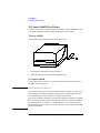
To Turn B1500A On
1. Connect the power cable from Agilent B1500A to an AC power outlet.
2. Connect the USB keyboard to the B1500A. Optionally, connect the USB mouse
to the B1500A.
3. Press the Standby switch (lower right corner of the front panel). Windows,
measurement module initialization, and self-calibration will start. For the
Windows logon screen, log on Windows.
After logging on, the Start EasyEXPERT button will be displayed on the screen.
To Turn B1500A Off
Press the Standby switch (lower right corner of the front panel). Windows will be
shutdown and the B1500A will become the standby state.
1-4
Agilent B1500 User’s Guide, Edition 7
Getting Started
To Turn On/Off B1500A
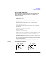
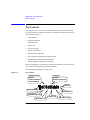
NOTE
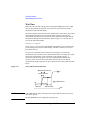
Agilent B1500A has the following front panel user interface.
•
Stop
Stops the present measurement or source output immediately.
•
Rotary knob
Rotating the knob moves the marker on the graph window, or
increases/decreases/changes the value in the active entry field.
Pressing the knob sets or enters the value.
•
Softkeys
Seven softkeys are available. Used to select one for the entry field specified or
the dialog box. They are also used to recall the test definitions (pre-defined test
setups).
•
Touch Panel Off
Enables or disables the touch screen operation.
•
Standby switch
Turns the B1500A on. Pressing the button in the ON state makes the B1500A in
the standby state.
•
LCD Off
Enables or disables the LCD panel. LED lights when the LCD is disabled.
•
Auto, -, +, Menu
Four keys are available for the display adjustment. Press Auto to perform
adjustment automatically. Use -, +, and Menu to adjust manually.
Agilent B1500A also requires Agilent EasyEXPERT software as its graphical user
interface. You can operate Agilent EasyEXPERT by using the touch panel. Use your
fingers, stylus pen, and so on for the touch panel operation. The USB keyboard and
the USB mouse are also available for operating the EasyEXPERT.
Agilent B1500 User’s Guide, Edition 7
1-5
Getting Started
To Launch EasyEXPERT
To Launch EasyEXPERT
1. Click the Start EasyEXPERT button, and wait until the EasyEXPERT main
screen or workspace selection screen is displayed.
NOTE
Workspace is the space created in Agilent B1500A’s internal hard disk drive, and is
used to store the test setup, test result data, and so on. The workspace can be created
and allocated for each user.
2. If this is the first time to start the EasyEXPERT, or if no workspace exists, a
workspace will be created automatically.
Skip to “To Use Application Test Mode” on page 1-10 or “To Use Classic Test
Mode” on page 1-12.
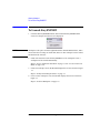
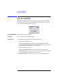
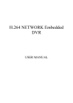
3. If only one workspace exists, the B1500A displays the screen as shown in Figure
1-1.
Skip to “If Only One Workspace Exists” on page 1-7.
4. If two or more workspaces exist, the B1500A displays the screen as shown in
Figure 1-3.
Skip to “To Select Workspace” on page 1-9.
1-6
Agilent B1500 User’s Guide, Edition 7
Getting Started
To Launch EasyEXPERT
If Only One Workspace Exists
For the screen as shown in Figure 1-1, perform the following steps.
1. If you do not want to create a workspace, select the Yes radio button and click
OK.
Skip to “To Use Application Test Mode” on page 1-10 or “To Use Classic Test
Mode” on page 1-12.
2. If you want to create a workspace, select the No radio button and click Next. The
B1500A displays the screen as shown in Figure 1-2.
Skip to “To Create Workspace” on page 1-8.
Figure 1-1
If Only One Workspace Exists
Agilent B1500 User’s Guide, Edition 7
1-7
Getting Started
To Launch EasyEXPERT
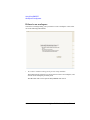
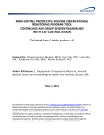
To Create Workspace
For the screen as shown in Figure 1-2, perform the following steps. To cancel
creating workspace, click Prev.
1. Enter the name of the new workspace into the above-entry field.
Check Allow other users to access this workspace box if you want to create a
public workspace that is opened for all users.
2. If you are the owner of the existing workspace, you can change the name of the
existing workspace.
If you want to rename the existing workspace, enter the name into the
below-entry field.
Check Allow other users to access this workspace box if you want to set it to a
public workspace that is opened for all users.
3. Click OK.
Skip to “To Use Application Test Mode” on page 1-10 or “To Use Classic Test
Mode” on page 1-12.
Figure 1-2
To Create Workspace
1-8
Agilent B1500 User’s Guide, Edition 7
Getting Started
To Launch EasyEXPERT
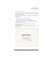
To Select Workspace
For the screen as shown in Figure 1-3, perform the following steps. This example
selects the workspace named as Demo Workspace that is a public workspace that is
opened for all users.
1. Select Public Workspaces owned by other users radio button.
2. Click Demo Workspace to select it.
3. Click Continue.
Skip to “To Use Application Test Mode” on page 1-10 or “To Use Classic Test
Mode” on page 1-12.
Figure 1-3
To Select Workspace
Agilent B1500 User’s Guide, Edition 7
1-9
Getting Started
To Use Application Test Mode
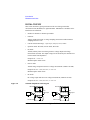
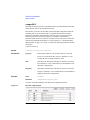
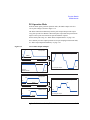
To Use Application Test Mode
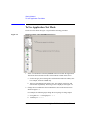
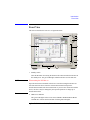
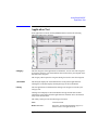
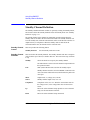
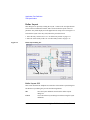
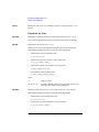
For the screen as shown in Figure 1-4, perform the following procedure.
Figure 1-4
Display Example of EasyEXPERT Main Screen
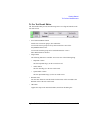
1. Select a test definition on the EasyEXPERT main screen while the Application
Test tab has been selected. The tab is in the leftmost column on the screen.
a. Set the Category area to change the test definitions listed in the Library area.
For example, check the CMOS only.
b. Select a test definition at the Library area. For example, click Id-Vg and
Select button sequentially. The Id-Vg screen is displayed. See Figure 1-5.
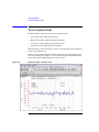
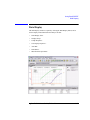
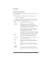
2. Change the test conditions at the Test Parameters area on the main screen as
shown in Figure 1-5.
For example, the following steps change the sweep range of voltage output.
a. Set VgStart to 0 V and VgStep to 0.2 V.
b. VsubsStep to -1.0 V.
1-10
Agilent B1500 User’s Guide, Edition 7
Getting Started
To Use Application Test Mode
To enter the value, use the USB keyboard or the screen/numeric keyboard opened by
clicking the button to the right of the entry field.
See “To Perform Measurement” on page 1-14 to start measurement.
NOTE
Test Definitions
Test definitions are the built-in test setups that have been defined and stored in the
EasyEXPERT as the application library. The EasyEXPERT contains more than two
hundred test definitions. You can execute the test without modifications. Also you
can create your own test setup/definition by making any changes. All furnished test
definitions are just sample. Agilent Technologies is NOT LIABLE for any damages
caused by the samples.
Figure 1-5
Display Example of Application Test Setup Screen
Agilent B1500 User’s Guide, Edition 7
1-11
Getting Started
To Use Classic Test Mode
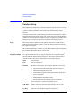
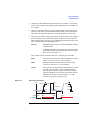
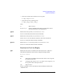
To Use Classic Test Mode
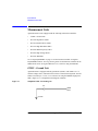
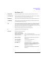
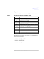
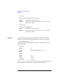
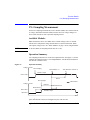
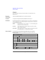
The following procedure performs the I/V Sweep classic test setup.
1. Click the Classic Test tab on the main screen. The tab is in the leftmost column
on the screen.
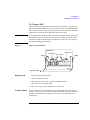
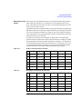
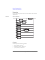
2. Click I/V Sweep and Select button sequentially. The I/V Sweep Channel Setup
screen is displayed. See Figure 1-6.
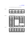
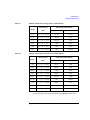
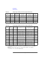
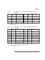
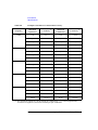
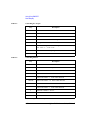
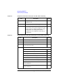
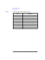
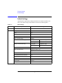
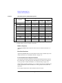
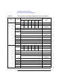
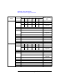
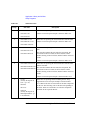
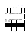
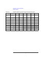
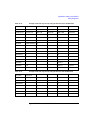
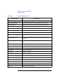
3. Set the Channel Setup parameters as shown in Table 1-1.
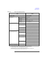
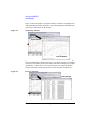
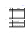
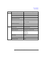
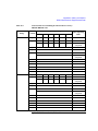
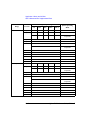
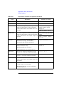
4. Click the Measurement Setup tab and set the parameters as shown in Table 1-2.
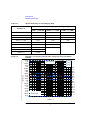
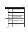
5. Click the Display Setup tab and set the parameters as shown in Table 1-3.
To enter the value, use the USB keyboard or the screen/numeric keyboard opened by
clicking the button to the right of the entry field.
Figure 1-6
Display Example of I/V Sweep Channel Setup Screen
1-12
Agilent B1500 User’s Guide, Edition 7
Getting Started
To Use Classic Test Mode
See “To Perform Measurement” on page 1-14 to start measurement.
Table 1-1
I/V Sweep Channel Setup
Unit
V Name
Mode a
I Name
Function
SMU1
V1
I1
V
VAR1
SMU2
V2
I2
V
CONST
a. Channel output mode. Set I or IPULSE for the current output and voltage measurement. Set V, VPULSE, or COMMON for the voltage output
and current measurement.
Table 1-2
I/V Sweep Measurement Setup
VAR1
Table 1-3
Timing
Constants
Unit
SMU1
Hold
0 s
Unit
SMU2
Name
V1
Delay
0 s
V Name
V2
Direction
Single
I Name
I2
Linear/Log
LINEAR
Mode
V
Start
0 V
Source
0 V
Stop
1 V
Compliance
100 mA
Step
10 mV
No of Step
101
Compliance
100 mA
Pwr Comp
OFF
Sweep
CONTINUE AT ANY
status
I/V Sweep Display Setup
Name
Sharing
Scale
Min
Max
X
V1
(None)
Linear
0 V
1 V
Y1
I1
(None)
Linear
-1 pA
1 pA
Agilent B1500 User’s Guide, Edition 7
1-13
Getting Started
To Perform Measurement
To Perform Measurement
1. Click the Single button (upper right on the main screen) to start measurement.
This opens the Data Display window and starts a single sweep measurement.
After the measurement, the measurement data is displayed on the Data Display
window. For the measurement after performing “To Use Classic Test Mode” on
page 1-12, you will have the test result as shown in Figure 1-7. This is the
leakage current measurement result because all measurement terminal is opened
for performing the procedures described in this chapter.
2. If the automatic data record function has been set to ON (Auto Record ON), Test
Result Editor appears on the lower area of the screen when the measurement is
completed. See “To Use Test Result Editor” on page 1-15.
Figure 1-7
Display Example of Data Display Window
1-14
Agilent B1500 User’s Guide, Edition 7
Getting Started
To Perform Measurement
To Use Test Result Editor
The Test Result Editor provides the following GUI to set a flag and remarks to the
test result record.
•
Save button and Delete button
Divides test records into groups, Save and Delete.
Test records in Save-group are always listed in the lower area of the
EasyEXPERT main screen.
Test records in Delete-group can be listed when Results > Filter >
Show Deleted Data is checked.
•
Flags buttons
The following buttons are available. You can set one of the following flags.
•
Important ! button
Sets the important flag (!) to the test result record.
•
Valid # button
Sets the valid flag (#) to the test result record.
•
Questionable ? button
Sets the questionable flag (?) to the test result record.
•
Remarks field
You can enter characters into this field. The characters will be recorded as the
Remarks value of the test result record.
•
OK button
Applies the setup on the Test Result Editor, and closes this dialog box.
Agilent B1500 User’s Guide, Edition 7
1-15
Getting Started
To Use Analysis Tools
To Use Analysis Tools
The Data Display window provides several analysis functions.
•
View menu: used to adjust the graph scale.
•
Marker menu: used to display and control the marker.
•
Cursor menu: used to display and control the cursor.
•
Line menu: used to display and control the lines.
When the marker, cursor, and lines are effective, their parameters are also displayed
on the X-Y Graph Plot area.
Figure 1-8 is an example displaying marker, tangent line, and regression line on the
test result graph shown in Figure 1-7. You can read position of the marker and the
active cursor, and interrupt and gradient of the active line.
Figure 1-8
Display Example of Analysis Tools
1-16
Agilent B1500 User’s Guide, Edition 7
2
Introduction
Introduction
This chapter describes the basic functions and features of Agilent B1500A
Semiconductor Device Analyzer, and consists of the following sections:
NOTE
•
“Overview”
•
“Front View”
•
“Rear View”
•
“Measurement Units”
•
“Specifications”
•
“Accessories and Options”
Application Library
Agilent B1500A has installed Agilent EasyEXPERT software as the user interface.
The EasyEXPERT contains an application library that is a set of test definitions. The
application test can be performed by selecting a test definition and setting the test
condition for the actual DUT (device under test).
All test definitions are just sample. If the samples damage your devices, Agilent
Technologies is NOT LIABLE for the damage.
NOTE
Utility
The folder C:\Program Files\Agilent\B1500\EasyEXPERT\Utilities stores the
following sample programs.
•
Prober control programs
•
4155/4156 setup file converter
•
sleep.exe program
For more details, see Chapter 10, “Application Library and Utilities.”
2- 2
Agilent B1500 User’s Guide, Edition 7
Introduction
Overview
Overview
Agilent B1500A Semiconductor Device Analyzer is the new generation one box
solution for the semiconductor device DC/AC parametric measurement and analysis
application. You can perform measurement and analysis easily and effectively on
the Microsoft Windows environment with intuitive graphical user interface, touch
screen LCD panel, keyboard, and mouse by using Agilent B1500A.
Agilent B1500A provides the DC voltage/current output capability, the DC
voltage/current measurement capability, and the AC signal output and impedance
measurement capability. So you can perform the current-voltage sweep
measurement and the capacitance-voltage sweep measurement for example by one
instrument. You can also analyze the measurement result characteristics graph by
using several tools such as markers, cursors, and lines.
Also, in the GPIB remote control mode, you can control the B1500A from an
external computer by using Agilent FLEX command set that is the common
language for Agilent semiconductor DC measurement instruments. So you can reuse
the measurement program created for Agilent 4155/4156/E5260/E5270.
Agilent B1500 User’s Guide, Edition 7
2- 3
Introduction
Overview
•
Agilent B1500A Semiconductor Device Analyzer
Mainframe that provides the ground unit (GNDU) and ten empty slots for the
measurement facilities, and Agilent EasyEXPERT software for the operating
environment. The EasyEXPERT is the GUI based measurement control and
analysis software runs on the Microsoft Windows XP Professional.
The B1500A is equipped with the 15 inch LCD with touch panel, hard disk
drive, DVD-ROM/CD-ROM/CD-RW drive, and USB/LAN/GP-IB interfaces.
The USB keyboard, the USB mouse, and the stylus pen are available as option.
•
Agilent B1510A HPSMU module
High power source/monitor unit module. Occupies two slots.
•
Agilent B1511A MPSMU module
Medium power source/monitor unit module. Occupies one slot.
•
Agilent B1517A HRSMU module
High resolution source/monitor unit module. Occupies one slot. Needs Agilent
E5288A ASU to perform atto level current measurement or automatic switching
of the measurement resource connection.
•
Agilent B1520A MFCMU module
Multi frequency capacitance measurement unit module. Occupies one slot.
Needs Agilent N1301A-100 SCUU to perform automatic switching of the
measurement resource connection.
•
Agilent B1525A SPGU module
High voltage semiconductor pulse generator unit module. Occupies one slot. Up
to five modules can be installed in one B1500A mainframe. One module
provides two output channels. Needs Agilent 16440A and 16445A to perform
automatic switching of the measurement resource connection.
•
Agilent B1530A WGFMU module and Agilent B1531A RSU
Waveform generator/fast measurement unit module and the remote-sense and
switch unit. Occupies one slot. Up to five modules can be installed in one
B1500A mainframe. One module provides two channels. See Agilent B1530A
User’s Guide for using the WGFMU.
•
Agilent 16440A SMU/Pulse Generator Selector
Used to switch the measurement resource connected to the DUT. The
measurement resource can be SPGU or SMU. Needs the 16445A adapter to use
the selector. One selector provides two switching channels.
2- 4
Agilent B1500 User’s Guide, Edition 7
Introduction
Overview
•
Agilent 16445A Selector Adapter
Used to connect the 16440A selector to the B1500A. Two selectors can be
connected.
•
Agilent E5288A ASU
Atto sense and switch unit (ASU). Used to enable the 1 pA range for the atto
level current measurement, also switch the measurement resource connected to
the DUT. The measurement resource can be HRSMU or the instrument
connected to the AUX terminal.
•
Agilent N1301A-100 SCUU
SMU CMU unify unit (SCUU). Used to switch the measurement resource
connected to the DUT. The measurement resource can be CMU or one of two
SMUs connected to the SCUU.
•
Agilent N1301A-200 GSWU
Guard switch unit (GSWU). Needs the SCUU to use the GSWU. Effective for
the accurate impedance measurements by connecting the guard lines between
CMU high and low near the DUT.
Agilent EasyEXPERT Software
Agilent EasyEXPERT software is a specially-designed Windows XP application
program for controlling Agilent B1500A. The EasyEXPERT provides the easy and
effective measurement and analysis environment with intuitive graphical user
interface (GUI), touch screen LCD panel, keyboard, and mouse. Some of the
functions are listed below.
•
Single measurement, repeat measurement, and append measurement
•
Switching matrix control
Supported models:
•
Agilent B2200A/B2201A switching matrix
•
Agilent E5250A switching matrix with E5252A (EasyEXPERT Plus edition)
•
Measurement/setup data management by workspace
•
Graph display and analysis with markers, cursors, and lines; and auto analysis
•
Data import/export capability, data output by CSV/XML format, and graph
output by EMF/BMP/GIF/PNG format
•
Maintenance; self-test and self-calibration
Agilent B1500 User’s Guide, Edition 7
2- 5
Introduction
Overview
The EasyEXPERT has the following measurement execution environments.
Application Test
•
Application test
•
Classic test
•
Quick test
The EasyEXPERT contains an application library that supports typical
measurements for CMOS devices, TFT, BJT, memory, nanotechnology devices such
as CNT FET, and so on. The application library includes more than two hundred test
definitions.
You can perform measurements by choosing the best one for your device under test
(DUT) from the application libraries, and modifying and executing it. Modification
is really simple. For example, it will be completed by changing the output voltage
only to DUT terminals. And the setup with your modifications can be saved and
recalled as your setup (My Favorite Setup).
Classic Test
You can perform measurements by using the user interface similar to the
semiconductor parameter analyzers such as Agilent 4156C. The setup can be made
by entering values into the setup tables used for the measurement module control.
And it can be saved and recalled as your setup (My Favorite Setup). This
measurement environment provides the following functions.
•
I/V Sweep
•
Multi Channel I/V Sweep
•
I/V List Sweep
•
I/V-t Sampling
•
C-V Sweep
•
SPGU Control
•
Switching Matrix Control
•
Direct Control
The Direct Control test mode is used to control the measurement modules directly
by using the B1500A GPIB control commands and perform measurement. For the
control commands, see “Agilent B1500A Programming Guide”.
Quick Test
You can execute the test setups saved in a preset group (My Favorite Setup)
sequentially.
2- 6
Agilent B1500 User’s Guide, Edition 7
Introduction
Front View
Front View
This section describes the front view of Agilent B1500A.
7
6
8
9
5
10
11
12
1
4
3
2
1. Standby switch
Turns the B1500A on. Pressing the button in the ON state makes the B1500A in
the standby state. The green LED lights when the B1500A is in the ON state.
NOTE
When turning the B1500A on
Open the measurement terminals at the device side when turning the B1500A on.
Also disconnect the device from the measurement terminals and open the
measurement terminals after the measurement. If you leave the connection with the
device, the device may be damaged by unexpected operations or charge-up of
measurement cables.
2. HDD access indicator
This green LED lights in the access status of HDD or DVD-ROM/CD-ROM/
CD-RW drive. Do not turn the B1500A off during this LED lights.
Agilent B1500 User’s Guide, Edition 7
2- 7
Introduction
Front View
3. OSD buttons
LCD Off enables or disables the LCD panel. The green LED lights when the
LCD is disabled.
Four keys are available for the display adjustment. Press Auto to perform
adjustment automatically. Use -, +, and Menu to adjust manually.
4. USB interfaces
USB, 2 ports. For keyboard, mouse, and so on. USB keyboard and USB mouse
are available as option.
5. LCD panel
15 inch TFT XGA display, 1024 × 768 resolution. Displays the Windows screen,
Agilent EasyEXPERT software window, and so on. Touch screen operation is
available when the Touch Panel Off indicator does not light.
NOTE
About screen adjustment
If you find swinging or flickering in screen while you use this instrument, perform
the screen adjustment. In most cases, the symptoms can be resolved by pressing the
Auto button below the LCD panel. The Auto button is used to start the automatic
screen adjustment. Also the manual screen adjustment is available by using the
adjustment menu displayed by pressing the Menu button.
6. Stop key
Stops the present measurement or source output immediately.
7. High voltage status indicator
This red LED lights when a source channel applies more than ± 42 V.
8. Measurement status indicator
This green LED lights when a measurement channel performs measurement.
9. Rotary knob
Works on Agilent EasyEXPERT environment. Rotating the knob moves the
marker on the graph window, or increases/decreases/changes the value in the
active entry field. Pressing the knob sets or enters the value.
10. Softkeys
Seven softkeys are available for Agilent EasyEXPERT environment. Used to
select an alternative for the entry field specified or the dialog box.
2- 8
Agilent B1500 User’s Guide, Edition 7
Introduction
Front View
11. DVD-ROM/CD-ROM/CD-RW drive
For data backup, B1500A update, or data transfer.
12. Touch Panel Off key
Works on Agilent EasyEXPERT environment. Enables or disables the touch
screen operation. The green LED lights when the touch screen is disabled.
NOTE
To disable the touch panel
Use Touch Panel Device Properties, and remove the check from the Enabled box on
the Advanced tab screen. The Touch Panel Device Properties dialog box can be
opened by selecting Gunze TPDD > Adjust Settings from Windows program menu.
6
7
8
9
5
10
11
12
1
4
3
Agilent B1500 User’s Guide, Edition 7
2
2- 9
Introduction
Rear View
Rear View
This section describes the rear view of Agilent B1500A.
E
D
4
D
D
D
3
D
2
5
D
C
B
A
1
13
12 11
10
9
8 7
6
1. Serial number
You need this serial number when using Agilent Technologies telephone
assistance program.
2. LED status indicator
For troubleshooting. Followings are some examples.
•
Both LEDs turn off:
B1500A is in the standby state and Standby switch is OFF position.
•
One LED turns green:
Power supply works normally.
•
Both LEDs turn orange:
B1500A is in the standby state and Standby switch is ON position.
2- 10
Agilent B1500 User’s Guide, Edition 7
Introduction
Rear View
3. LINE input receptacle
AC power cable is connected to this receptacle.
4. GPIB interface
Use an Agilent 82357A USB/GPIB interface or Agilent 10833A/B/C/D GPIB
cable to connect to an external computer or equipment.
5. Module slot
Ten slots are available for installing the modules. Several kinds of module can
be installed in the B1500A. However, the allowable number to install is different
by the module type. See “Measurement Units” on page 2-16. Also, there is a rule
for the installation order by the module type. See Chapter 3, “Installation.”
If the WGFMU is installed, the following condition must be satisfied by the
modules installed in the B1500A.
Total rating (sum of ratings set to modules) < 60
Rating of module: HPSMU 14, MPSMU 2, HRSMU 2, CMU 7, SPGU 12,
WGFMU 10
For example, if the B1500A installs two HPSMU, one CMU, and two WGFMU,
the total rating is 2×14+7+2×10=55.
6. Circuit Common (
) and Frame ground (
) terminals
Normally, connect the terminals together by using the shorting bar (Agilent part
number 5000-4206). For floating measurement, remove the shorting bar.
CAUTION
For floating measurement, do not apply voltage more than ±42 V to the Circuit
Common terminal. Failure to heed this caution may result in damage to the B1500A.
WARNING
If the Circuit Common terminal is not connected to the frame ground terminal
(for floating measurement), a potential shock hazard may present. Do not
touch any of measurement circuit at any time while a floating measurement is
in progress.
7. Zero Check terminal
Ground reference point of the B1500A.
CAUTION
The Zero Check terminal can be used for the service purpose only. For the B1500A
normal operation, leave this terminal open and do not connect anything to this
terminal. Connecting anything can damage the B1500A.
Agilent B1500 User’s Guide, Edition 7
2- 11
Introduction
Rear View
8. GNDU terminal
0 V constant voltage source. Used for the reference of measurement ground.
Triaxial connector.
9. LAN interface
RJ45 connector.
10. USB interfaces
USB, 2 ports. For keyboard, mouse, or peripherals. USB keyboard and USB
mouse are available as option.
11. Ext Trig terminals
Two BNC connectors, one for trigger input, and one for trigger output. For
details about the trigger function, see Programming Guide.
12. Digital I/O terminal
DSUB 25 pin connector. Can be used for the trigger input/output terminals or an
interface to control an external relay circuit and so on. For details, see
Programming Guide. This connector is also used to connect Agilent 16445A
selector adapter.
13. Interlock terminal
Used in conjunction with the interlock function of the B1500A. If the Interlock
terminal is open, maximum SMU output is limited to ±42 V. Be sure to connect
this terminal to the 16442B test fixture or connector plate before performing
measurement. If you use a connector plate, you must install an interlock circuit.
For details on how to install the interlock circuit, see “To Make an Interlock
Circuit” on page 3-29.
WARNING
Dangerous voltage of up to the maximum voltage of SMUs may be present at
force, guard, and sense terminals if the Interlock terminal is closed.
2- 12
Agilent B1500 User’s Guide, Edition 7
Introduction
Rear View
E
D
4
D
D
D
3
5
D
2
D
C
B
A
1
13
12 11
10
9
8 7
6
A. GNDU/ADC
Ground unit and A/D converter module. Always installed in the B1500A.
B. SPGU module
The semiconductor pulse generator unit (SPGU) has the Output 1 and Output 2
terminals and the following terminals to synchronize the operation between
SPGUs or with an external equipment.
Ref Out/Sync Out: Connect to the Ref In/Sync In of the slave SPGU.
Ref In/Sync In: Connect to the Ref Out/Sync Out of the master SPGU.
Trig Out: Connect to the trigger input terminal of the equipment synchronized
with the SPGU output.
CAUTION
Connect the Ref Out/In, Sync Out/In, and Trig Out terminals to the specified
terminal properly. Connecting to the other terminal may result in damage to the
SPGU.
Agilent B1500 User’s Guide, Edition 7
2- 13
Introduction
Rear View
In the EasyEXPERT operation mode, the SPGU outputs can be specified by the
PG number. PG1 and PG2 are assigned to the Output 1 and Output 2 terminals
of the SPGU at the lowest position. And the following PG numbers are assigned
to the outputs of the upper SPGUs in sequence. Use the PG number label
furnished with the B1500A or equivalent to identify the SPGU channel number.
C. WGFMU module
The waveform generator/fast measurement unit (WGFMU) has the Ch 1 and Ch
2 terminals and the following terminals to synchronize the operation between
WGFMUs or with an external equipment.
Sync Out: Connect to the Sync In of the slave WGFMU.
Sync In: Connect to the Sync Out of the master WGFMU.
Trig Out: Connect to the trigger input terminal of the equipment synchronized
with the WGFMU output.
CAUTION
Connect the Sync Out/In, and Trig Out terminals to the specified terminal properly.
Connecting to the other terminal may result in damage to the WGFMU.
Connect the connection cable between the WGFMU and the RSU (remote-sense and
switch unit) before turning the B1500A on. Changing the cable connection in the
power on state may damage the WGFMU and RSU. See Agilent B1530A User’s
Guide for cable connection and usage.
D. SMU module
The source/monitor unit (SMU) has two triaxial connectors, force and sense, for
the Kelvin connections. The HRSMU (high resolution SMU) also provides a
D-sub connector (To ASU terminal) which is used to connect the dedicated ASU
(atto sense and switch unit). The HPSMU (high power SMU) occupies two slots.
In the EasyEXPERT operation mode, the SMUs can be specified by the SMU
number. SMU1 is assigned to the SMU at the lowest position. And the following
SMU numbers are assigned to the upper SMUs in sequence. Use the SMU
number label furnished with the B1500A or equivalent to identify the SMU
number.
NOTE
To use the ASU, connect the connection cables between the HRSMU and the
dedicated ASU before turning the B1500A on.
2- 14
Agilent B1500 User’s Guide, Edition 7
Introduction
Rear View
WARNING
There are potentially hazardous voltages (200 V for HPSMU, and 100 V for
MPSMU/HRSMU/ASU) present at the Force, Sense, and Guard terminals of
Agilent B1500A. To prevent electrical shock, the following safety precautions
must be observed during the use of the B1500A.
a. Use a three-conductor AC power cable to connect the cabinet (if used)
and the B1500A to an electrical ground (safety ground).
b. If you do not use the 16442B test fixture, you must install and connect an
interlock circuit that opens the Interlock terminal when the shielding
box access door is opened.
c. Confirm periodically that the interlock function works normally.
d. Before touching the connections on the Force, Guard, and Sense
terminals, turn the B1500A off and discharge any capacitors. If you do
not turn the B1500A off, complete all of the following items, regardless
of the B1500A settings.
•
Press the Stop key to set the module output off.
•
Confirm that the High Voltage indicator is not lit.
•
Open the shielding box access door (open the Interlock terminal).
•
Discharge any capacitors connected to an SMU.
e. Warn persons working around the B1500A about dangerous conditions.
E. CMU module
The multi frequency capacitance measurement unit (MFCMU) has four coaxial
connectors, Lcur, Lpot, Hpot, and Hcur, for the four-terminal pair connection.
The Hcur and Hpot have to be connected together at a terminal of the device
under test (DUT). Also the Lcur and Lpot have to be connected together at the
other terminal of the DUT. Then, the guard lines of four-terminal pair must be
connected together.
CAUTION
Do not apply voltage more than ±25 V to the MFCMU input terminals. Failure to
heed this caution may result in damage to the module.
Agilent B1500 User’s Guide, Edition 7
2- 15
Introduction
Measurement Units
Measurement Units
Agilent B1500A can be equipped with the following measurement modules.
•
“GNDU - Ground Unit”
•
“B1510A High Power SMU”
•
“B1511A Medium Power SMU”
•
“B1517A High Resolution SMU”
•
“B1520A Multi Frequency CMU”
•
“B1525A High Voltage SPGU”
•
“B1530A WGFMU”
See “Using EasyEXPERT” on page 4-1 for the functions available for Agilent
EasyEXPERT software. See Programming Guide for the functions available for the
GPIB remote mode. See Agilent B1530A User’s Guide for using the WGFMU.
GNDU - Ground Unit
Agilent B1500A is equipped with the ground unit (GNDU). The GNDU is a 0 V
constant voltage source, and used for the reference of measurement ground. Also the
GNDU can sink up to ± 4.2 A, so it is effective for using the HPSMU (high power
SMU). Figure 2-1 is a simplified circuit diagram of GNDU.
Figure 2-1
Simplified GNDU Circuit Diagram
9
*1'8
)RUFH
&RPPRQ
2- 16
Agilent B1500 User’s Guide, Edition 7
Introduction
Measurement Units
About SMU
Source/monitor unit (SMU) can apply DC voltage or current, and can measure DC
current or voltage. Figure 2-2 is a simplified SMU circuit diagram. The SMU can
perform the following operations:
•
Apply voltage and measures current
•
Apply current and measures voltage
•
Apply voltage and measures voltage
•
Apply current and measures current
NOTE
To select the SMU operation mode in the GPIB remote condition, enter the CMM
command.
Figure 2-2
Simplified SMU Circuit Diagram
$ 608
)RUFH
9
&RPPRQ
Compliance
The SMU has a compliance feature that limits output voltage or current to prevent
damage to the device under test. When the SMU applies voltage, you can specify
current compliance. When the SMU applies current, you can specify voltage
compliance. For details about the compliance, refer to “SMU Compliance” on page
7-53.
Agilent B1500 User’s Guide, Edition 7
2- 17
Introduction
Measurement Units
B1510A High Power SMU
This section describes typical specification of the high power source/monitor unit
(HPSMU) for Agilent B1500A. Maximum four modules can be installed in one
mainframe.
Figure 2-3
•
Maximum voltage, current, output power: ± 200 V, ± 1 A, 20 W
•
Minimum range: 2 V, 1 nA
•
Output/measurement value and resolution: see Table 2-1 to Table 2-4.
HPSMU Output and Measurement Ranges
&XUUHQWP$
9ROWDJH9
2- 18
Agilent B1500 User’s Guide, Edition 7
Introduction
Measurement Units
Table 2-1
Table 2-2
HPSMU Output Voltage Ranges and Resolutions
Range
Output Value
Setting
Resolution
Maximum
Current
2V
0 ≤ |V| ≤ 2 V
100 μV
± 1000 mA
20 V
0 ≤ |V| ≤ 20 V
1 mV
± 1000 mA
40 V
0 ≤ |V| ≤ 40 V
2 mV
± 500 mA
100 V
0 ≤ |V| ≤ 100 V
5 mV
± 125 mA
200 V
0 ≤ |V| ≤ 200 V
10 mV
± 50 mA
HPSMU Output Current Ranges and Resolutions
Range
Output Value
Setting
Resolution
Maximum
Voltage
1 nA
0 ≤ |I| ≤ 1.15 nA
50 fA
± 200 V
10 nA
0 ≤ |I| ≤ 11.5 nA
500 fA
± 200 V
100 nA
0 ≤ |I| ≤ 115 nA
5 pA
± 200 V
1 μA
0 ≤ |I| ≤ 1.15 μA
50 pA
± 200 V
10 μA
0 ≤ |I| ≤ 11.5 μA
500 pA
± 200 V
100 μA
0 ≤ |I| ≤ 115 μA
5 nA
± 200 V
1 mA
0 ≤ |I| ≤ 1.15 mA
50 nA
± 200 V
10 mA
0 ≤ |I| ≤ 11.5 mA
500 nA
± 200 V
100 mA
0 ≤ |I| ≤ 50 mA
5 μA
± 200 V
50 mA < |I| ≤ 115 mA
5 μA
± 100 V
0 ≤ |I| ≤ 50 mA
50 μA
± 200 V
50 mA < |I| ≤ 125 mA
50 μA
± 100 V
125 mA < |I| ≤ 500 mA
50 μA
± 40 V
500 mA < |I| ≤ 1 A
50 μA
± 20 V
1A
Agilent B1500 User’s Guide, Edition 7
2- 19
Introduction
Measurement Units
Table 2-3
HPSMU Measurement Voltage Values and Resolutions
Table 2-4
Measurement Resolutions
Measurement
Value a
High Speed ADC
High Resolution ADC
2V
0 ≤ |V| ≤ 2.2 V
100 μV
2 μV
20 V
0 ≤ |V| ≤ 22 V
1 mV
20 μV
40 V
0 ≤ |V| ≤ 44 V
2 mV
40 μV
100 V
0 ≤ |V| ≤ 110 V
5 mV
100 μV
200 V
0 ≤ |V| ≤ 200 V
10 mV
200 μV
Range
HPSMU Measurement Current Values and Resolutions
Measurement Resolutions
Range
Measurement Value a
High Speed ADC
High Resolution ADC
1 nA
0 ≤ |I| ≤ 1.15 nA
50 fA
10 fA
10 nA
0 ≤ |I| ≤ 11.5 nA
500 fA
10 fA
100 nA
0 ≤ |I| ≤ 115 nA
5 pA
100 fA
1 μA
0 ≤ |I| ≤ 1.15 μA
50 pA
1 pA
10 μA
0 ≤ |I| ≤ 11.5 μA
500 pA
10 pA
100 μA
0 ≤ |I| ≤ 115 μA
5 nA
100 pA
1 mA
0 ≤ |I| ≤ 1.15 mA
50 nA
1 nA
10 mA
0 ≤ |I| ≤ 11.5 mA
500 nA
10 nA
100 mA
0 ≤ |I| ≤ 115 mA
5 μA
100 nA
1A
0 ≤ |I| ≤ 1 A
50 μA
1 μA
a. This column is applied to the auto ranging or the limited auto ranging. For
fixed ranging, maximum measurement value is Range column value.
2- 20
Agilent B1500 User’s Guide, Edition 7
Introduction
Measurement Units
B1511A Medium Power SMU
This section describes typical specification of the medium power source/monitor
unit (MPSMU) for Agilent B1500A.
Figure 2-4
•
Maximum voltage, current, output power: ± 100 V, ± 100 mA, 2 W
•
Minimum range: 0.5 V, 1 nA
•
Output/measurement value and resolution: see Table 2-5 to Table 2-8.
MPSMU Output and Measurement Ranges
&XUUHQWP$
9ROWDJH9
Agilent B1500 User’s Guide, Edition 7
2- 21
Introduction
Measurement Units
Table 2-5
MPSMU Output Voltage Ranges and Resolutions
Range
0.5 V
Maximum
Current
0 ≤ |V| ≤
0.5 V
25 μV
± 100 mA
2V
0 ≤ |V| ≤
2V
100 μV
± 100 mA
5V
0 ≤ |V| ≤
5V
250 μV
± 100 mA
20 V
0 ≤ |V| ≤
20 V
1 mV
± 100 mA
0 ≤ |V| ≤ 20 V
2 mV
± 100 mA
20 V < |V| ≤ 40 V
2 mV
± 50 mA
5 mV
± 100 mA
20 V < |V| ≤ 40 V
5 mV
± 50 mA
40 V < |V| ≤ 100 V
5 mV
± 20 mA
40 V
100 V
Table 2-6
Setting
Resolution
Output Value
0 ≤ |V| ≤
20 V
MPSMU Output Current Ranges and Resolutions
Range
Output Value
Setting
Resolution
Maximum
Voltage
1 nA
0 ≤ |I| ≤ 1.15 nA
50 fA
± 100 V
10 nA
0 ≤ |I| ≤ 11.5 nA
500 fA
± 100 V
100 nA
0 ≤ |I| ≤ 115 nA
5 pA
± 100 V
1 μA
0 ≤ |I| ≤ 1.15 μA
50 pA
± 100 V
10 μA
0 ≤ |I| ≤ 11.5 μA
500 pA
± 100 V
100 μA
0 ≤ |I| ≤ 115 μA
5 nA
± 100 V
1 mA
0 ≤ |I| ≤ 1.15 mA
50 nA
± 100 V
10 mA
0 ≤ |I| ≤ 11.5 mA
500 nA
± 100 V
100 mA
0 ≤ |I| ≤ 20 mA
5 μA
± 100 V
20 mA < |I| ≤ 50 mA
5 μA
± 40 V
50 mA < |I| ≤ 100 mA
5 μA
± 20 V
2- 22
Agilent B1500 User’s Guide, Edition 7
Introduction
Measurement Units
Table 2-7
MPSMU Measurement Voltage Values and Resolutions
Table 2-8
Measurement Resolutions
Measurement
Value a
High Speed ADC
High Resolution ADC
0.5 V
0 ≤ |V| ≤ 0.55 V
25 μV
0.5 μV
2V
0 ≤ |V| ≤ 2.2 V
100 μV
2 μV
5V
0 ≤ |V| ≤ 5.5 V
250 μV
5 μV
20 V
0 ≤ |V| ≤ 22 V
1 mV
20 μV
40 V
0 ≤ |V| ≤ 44 V
2 mV
40 μV
100 V
0 ≤ |V| ≤ 100 V
5 mV
100 μV
Range
MPSMU Measurement Current Values and Resolutions
Measurement Resolutions
Measurement
Value a
High Speed ADC
High Resolution ADC
1 nA
0 ≤ |I| ≤ 1.15 nA
50 fA
10 fA
10 nA
0 ≤ |I| ≤ 11.5 nA
500 fA
10 fA
100 nA
0 ≤ |I| ≤ 115 nA
5 pA
100 fA
1 μA
0 ≤ |I| ≤ 1.15 μA
50 pA
1 pA
10 μA
0 ≤ |I| ≤ 11.5 μA
500 pA
10 pA
100 μA
0 ≤ |I| ≤ 115 μA
5 nA
100 pA
1 mA
0 ≤ |I| ≤ 1.15 mA
50 nA
1 nA
10 mA
0 ≤ |I| ≤ 11.5 mA
500 nA
10 nA
100 mA
0 ≤ |I| ≤ 100 mA
5 μA
100 nA
Range
a. This column is applied to the auto ranging or the limited auto ranging.
For fixed ranging, maximum measurement value is Range column value.
Agilent B1500 User’s Guide, Edition 7
2- 23
Introduction
Measurement Units
B1517A High Resolution SMU
This section describes typical specification of the high resolution source/monitor
unit (HRSMU) for Agilent B1500A.
Figure 2-5
•
Maximum voltage, current, output power: ± 100 V, ± 100 mA, 2 W
•
Minimum range: 0.5 V, 10 pA (1 pA when the E5288A ASU is used)
•
Output/measurement value and resolution: see Table 2-9 to Table 2-12.
HRSMU Output and Measurement Ranges
&XUUHQWP$
9ROWDJH9
2- 24
Agilent B1500 User’s Guide, Edition 7
Introduction
Measurement Units
Table 2-9
HRSMU Output Voltage Ranges and Resolutions
Range
Output Value
Setting
Resolution
Maximum
Current
0.5 V
0 ≤ |V| ≤ 0.5 V
25 μV
± 100 mA
2V
0 ≤ |V| ≤ 2 V
100 μV
± 100 mA
5V
0 ≤ |V| ≤ 5 V
250 μV
± 100 mA
20 V
0 ≤ |V| ≤ 20 V
1 mV
± 100 mA
40 V
0 ≤ |V| ≤ 20 V
2 mV
± 100 mA
20 V < |V| ≤ 40 V
2 mV
± 50 mA
0 ≤ |V| ≤ 20 V
5 mV
± 100 mA
20 V < |V| ≤ 40 V
5 mV
± 50 mA
40 V < |V| ≤ 100 V
5 mV
± 20 mA
100 V
Table 2-10
HRSMU Output Current Ranges and Resolutions
Range
Output Value
Setting
Resolution
Maximum
Voltage
1 pA a
0 ≤ |I| ≤ 1.15 pA
1 fA
± 100 V
10 pA
0 ≤ |I| ≤ 11.5 pA
5 fA
± 100 V
100 pA
0 ≤ |I| ≤ 115 pA
5 fA
± 100 V
1 nA
0 ≤ |I| ≤ 1.15 nA
50 fA
± 100 V
10 nA
0 ≤ |I| ≤ 11.5 nA
500 fA
± 100 V
100 nA
0 ≤ |I| ≤ 115 nA
5 pA
± 100 V
1 μA
0 ≤ |I| ≤ 1.15 μA
50 pA
± 100 V
10 μA
0 ≤ |I| ≤ 11.5 μA
500 pA
± 100 V
100 μA
0 ≤ |I| ≤ 115 μA
5 nA
± 100 V
1 mA
0 ≤ |I| ≤ 1.15 mA
50 nA
± 100 V
10 mA
0 ≤ |I| ≤ 11.5 mA
500 nA
± 100 V
100 mA
0 ≤ |I| ≤ 20 mA
5 μA
± 100 V
20 mA < |I| ≤ 50 mA
5 μA
± 40 V
50 mA < |I| ≤ 100 mA
5 μA
± 20 V
a. Available when the E5288A Atto Sense and Switch Unit (ASU) is used.
Agilent B1500 User’s Guide, Edition 7
2- 25
Introduction
Measurement Units
Table 2-11
HRSMU Measurement Voltage Values and Resolutions
Table 2-12
Measurement Resolutions
Measurement
Value a
High Speed ADC
High Resolution ADC
0.5 V
0 ≤ |V| ≤ 0.55 V
25 μV
0.5 μV
2V
0 ≤ |V| ≤ 2.2 V
100 μV
2 μV
5V
0 ≤ |V| ≤ 5.5 V
250 μV
5 μV
20 V
0 ≤ |V| ≤ 22 V
1 mV
20 μV
40 V
0 ≤ |V| ≤ 44 V
2 mV
40 μV
100 V
0 ≤ |V| ≤ 100 V
5 mV
100 μV
Range
HRSMU Measurement Current Values and Resolutions
Measurement Resolutions
Measurement
Value a
High Speed ADC
High Resolution ADC
1 pA b
0 ≤ |I| ≤ 1.15 pA
100 aA
100 aA
10 pA
0 ≤ |I| ≤ 11.5 pA
1 fA
1 fA / 400 aA b
100 pA
0 ≤ |I| ≤ 115 pA
5 fA
2 fA / 500 aA b
1 nA
0 ≤ |I| ≤ 1.15 nA
50 fA
10 fA
10 nA
0 ≤ |I| ≤ 11.5 nA
500 fA
10 fA
100 nA
0 ≤ |I| ≤ 115 nA
5 pA
100 fA
1 μA
0 ≤ |I| ≤ 1.15 μA
50 pA
1 pA
10 μA
0 ≤ |I| ≤ 11.5 μA
500 pA
10 pA
100 μA
0 ≤ |I| ≤ 115 μA
5 nA
100 pA
1 mA
0 ≤ |I| ≤ 1.15 mA
50 nA
1 nA
10 mA
0 ≤ |I| ≤ 11.5 mA
500 nA
10 nA
100 mA
0 ≤ |I| ≤ 100 mA
5 μA
100 nA
Range
a. This column is applied to the auto ranging or the limited auto ranging.
For fixed ranging, maximum measurement value is Range column value.
b. Available when the E5288A Atto Sense and Switch Unit (ASU) is used.
2- 26
Agilent B1500 User’s Guide, Edition 7
Introduction
Measurement Units
NOTE
To connect ASU
The specifications are satisfied and guaranteed for the exclusive combination of the
ASU and the HRSMU. So confirm the serial number of the ASU and connect it to
the dedicated HRSMU properly.
To connect the ASU, see “To Connect ASU” on page 3-17.
To confirm the serial number, see “ASU” on page 4-43.
NOTE
Before using 1 pA range
The measurement channel connected to the ASU supports the 1 pA range. To use the
1 pA range, set the 1 pA fixed range or the 1 pA limited auto ranging.
The B1500A automatically performs the compensation of the data measured by the
1 pA range and returns the compensated data. You can use either the pre-stored
offset data or the pre-measured offset data.
To measure the offset data, perform the self-calibration before starting the
measurement for a DUT. This offset data is temporarily memorized until the
B1500A is turned off. See “Module Self Calibration” on page 4-35.
Agilent B1500 User’s Guide, Edition 7
2- 27
Introduction
Measurement Units
B1520A Multi Frequency CMU
This section describes typical specification of the multi frequency capacitance
measurement unit (CMU) for Agilent B1500A. The CMU performs the impedance
measurement and returns the specified measurement data such as Cp-G. Only one
module can be installed in one mainframe.
•
Measurement parameters: See Table 2-13.
All measurement parameters are supported by Agilent B1500A in the GPIB
remote mode. However, Agilent EasyEXPERT software supports the Cp-G,
Cp-D, Cs-Rs, and Z-θ measurements only.
•
AC signal, output frequency:
1 kHz to 5 MHz
Setting resolution: 1 mHz (1 kHz to), 10 mHz (10 kHz to), 0.1 Hz (100 kHz to),
or 1 Hz (1 MHz to 5 MHz)
•
AC signal, output level:
10 mVrms to 250 mVrms, 1 mV resolution
•
DC bias:
0 to ± 100 V
Setting resolution: 1 mV (0 to ± 25 V) or 5 mV (to ± 100 V)
DC bias > ± 25 V is available when using the SMU CMU unify unit (SCUU).
•
Measurement range:
For the fixed ranging mode, measurement range (impedance range) must be
specified to perform measurement. Table 2-14 shows the available measurement
ranges and the corresponding impedance value. And Figure 2-6 shows the
calculation example of the impedance vs frequency characteristics of a
capacitive load. Use these information to decide the measurement range.
Impedance Z is calculated by the following formula.
Z = 1 / (2π f C)
where f is frequency (Hz) and C is capacitance (F).
2- 28
Agilent B1500 User’s Guide, Edition 7
Introduction
Measurement Units
Table 2-13
Measurement Parameters
Primary Parameter
Secondary Parameter
R (resistance, Ω)
X (reactance, Ω)
G (conductance, S)
B (susceptance, S)
Z (impedance, Ω)
θ (phase, radian)
Z (impedance, Ω)
θ (phase, degree)
Y (admittance, S)
θ (phase, radian)
Y (admittance, S)
θ (phase, degree)
Cp (parallel capacitance, F)
G (conductance, S)
Cp (parallel capacitance, F)
D (dissipation factor)
Cp (parallel capacitance, F)
Q (quality factor)
Cp (parallel capacitance, F)
Rp (parallel resistance, Ω)
Cs (series capacitance, F)
Rs (series resistance, Ω)
Cs (series capacitance, F)
D (dissipation factor)
Cs (series capacitance, F)
Q (quality factor)
Lp (parallel inductance, H)
G (conductance, S)
Lp (parallel inductance, H)
D (dissipation factor)
Lp (parallel inductance, H)
Q (quality factor)
Lp (parallel inductance, H)
Rp (parallel resistance, Ω)
Ls (series inductance, H)
Rs (series resistance, Ω)
Ls (series inductance, H)
D (dissipation factor)
Ls (series inductance, H)
Q (quality factor)
Agilent B1500 User’s Guide, Edition 7
2- 29
Introduction
Measurement Units
Table 2-14
Measurement Range for Fixed Ranging Mode
Measurement range (impedance range)
Impedance Z
1 kHz ≤ f ≤ 200 kHz
200 kHz < f ≤ 2 MHz
2 MHz < f ≤ 5 MHz
0 ≤ Z < 100 Ω
50 Ω
50 Ω
50 Ω
100 Ω ≤ Z < 300 Ω
100 Ω
100 Ω
100 Ω
300 Ω ≤ Z < 1 kΩ
300 Ω
300 Ω
300 Ω
1 kΩ ≤ Z < 3 kΩ
1 kΩ
1 kΩ
1 kΩ
3 kΩ ≤ Z < 10 kΩ
3 kΩ
3 kΩ
3 kΩ
10 kΩ ≤ Z < 30 kΩ
10 kΩ
10 kΩ
30 kΩ ≤ Z < 100 kΩ
30 kΩ
30 kΩ
100 kΩ ≤ Z < 300 kΩ
100 kΩ
300 kΩ ≤ Z
300 kΩ
Impedance vs Frequency Characteristics of Capacitive Load, Calculation
Example
Impedance Z
Figure 2-6
10 T7
1 T7
100 G7
10 G7
1 G7
100 M7
10 M7
1 M7
100 k7
10 k7
1 k7
100 7
10 7
17
100 m7
10 m7
1 m7
100 M7
10 M7
1 M7
100 n7
10 n7
1 kHz
300 k7 range
3 k7
range
100 aF
1 fF
10 fF
100 fF
1 pF
10 pF
100 pF
1 nF
10 nF
100 nF
1 MF
10 MF
100 MF
1 mF
10 mF
100 mF
1F
50 7 range
10 kHz
100 kHz
1 MHz
5 MHz
Frequency f
2- 30
Agilent B1500 User’s Guide, Edition 7
Introduction
Measurement Units
B1525A High Voltage SPGU
This section describes key specification of the high voltage semiconductor pulse
generator unit (SPGU) for Agilent B1500A. Maximum five modules can be
installed in one mainframe.
•
Number of output channels: 2 channels per module
•
Output impedance: 50 Ω
•
Output level: 0 to ± 40 V (open load), ± 20 V (50 Ω load), 1 mV resolution
•
SPGU operation mode:
PG (pulse generator) or ALWG (arbitrary linear waveform generator)
•
Channel output operation mode:
Free run, duration, or pulse count (PG mode)/sequence count (ALWG mode)
•
PG output mode:
2-level pulse or 3-level pulse, for each channel
•
Pulse timing parameters:
Period: 20 ns to 10 s, 10 ns resolution
Width: 10 ns to period-10 ns, resolution 2.5 ns or 10 ns (transition time > 8 μs)
Delay: 0 to period-20 ns, resolution 2.5 ns or 10 ns (transition time > 8 μs)
Transition time (leading time or trailing time): 8 ns to 400 ms, resolution 2 ns or
8 ns (transition time > 8 μs)
Figure 2-7
•
Pulse switch, which is more durable than mechanical relays, and better suited for
frequent switching applications.
•
Automatic voltage level adjustment by specifying load impedance of DUT
SPGU Simplified Circuit Diagram
50 7
Pulse switch
50 7
Pulse switch
Output 1
PG 2-level
or 3-level
or
ALWG
Agilent B1500 User’s Guide, Edition 7
Output 2
PG 2-level
or 3-level
or
ALWG
2- 31
Introduction
Measurement Units
B1530A WGFMU
This section describes typical specification of the waveform generator/fast
measurement unit (WGFMU) for Agilent B1500A. Maximum five modules can be
installed in one mainframe.
•
Number of channels: 2 channels per module
•
Function:
Voltage output and current or voltage sampling measurement with minimum
sampling interval of 5 ns
•
Current measurement range: 1 μA, 10 μA, 100 μA, 1 mA, 10 mA
•
Operation mode: PG mode, Fast IV mode, DC mode
•
PG mode:
ALWG (arbitrary linear waveform generator) voltage output and voltage
measurement (VFVM). The output voltage will be divided by the internal 50 Ω
resistor and the load impedance.
Output level: -5 V to 5 V
Minimum pulse width: 100 ns
•
Fast IV mode:
ALWG voltage output and current or voltage measurement (VFIM or VFVM).
Output level: 0 to -10 V, 0 to 10 V, -5 V to 5 V
Minimum pulse width: 300 ns
•
DC mode:
DC voltage output and current or voltage measurement (VFIM or VFVM).
Output level: 0 to -10 V, 0 to 10 V, -5 V to 5 V
Figure 2-8
WGFMU Simplified Circuit Diagram
PG mode
50 7
Ch1
RSU output
ALWG
A
Fast IV mode
2- 32
PG mode
V
V
50 7
V
Ch2
RSU output
ALWG
A
Fast IV mode
V
Agilent B1500 User’s Guide, Edition 7
Introduction
Specifications
Specifications
This section lists specifications and supplemental information for the B1500A and
its associated modules. The specifications are the standards against which the
B1500A and its associated modules are tested. When the B1500A and any of its
associated modules are shipped from the factory, they meet the specifications. The
“supplemental” information and “typical” entries in the following specifications are
not warranted, but provide useful information about the functions and performance
of the instrument.
Hardware
•
“Specification Conditions”
•
“Mainframe”
•
“MPSMU/HRSMU”
•
“ASU”
•
“HPSMU”
•
“SMU Common Specifications”
•
“SMU Supplemental Information”
•
“MFCMU”
•
“SCUU/GSWU”
•
“HV-SPGU”
•
“Selector”
•
“Selector Adapter”
•
“WGFMU/RSU”
Agilent B1500 User’s Guide, Edition 7
2- 33
Introduction
Specifications
Specification Conditions
The measurement and output accuracy are specified at the rear panel connector
terminals when referenced to the Zero Check terminal. The B1530A WGFMU
measurement and output accuracy are specified at the output terminal of the RSU.
Accuracy is specified under the following conditions:
1. Temperature: 23 °C ± 5 °C
2. Humidity: 20 % to 60 %
3. After 40 minutes warm-up followed by self-calibration
4. Ambient temperature change less than ± 1 °C after self-calibration execution,
not applicable for MFCMU
5. Measurement made within one hour after self-calibration execution,
not applicable for MFCMU and WGFMU
6. Calibration period: 1 year
7. SMU integration time setting:
1 PLC (1 nA to 1 A range, voltage range)
20 PLC (100 pA range)
50 PLC (1 pA to 10 pA range)
Averaging of high speed ADC: 128 samples per 1 PLC
8. SMU filter: ON
9. SMU measurement terminal connection: Kelvin connection
10. WGFMU load capacitance: 25 pF or less
NOTE
Agilent Technologies is responsible for removing, installing, and replacing the
B1500A modules. Contact your nearest Agilent Technologies to install and calibrate
the B1500A modules.
2- 34
Agilent B1500 User’s Guide, Edition 7
Introduction
Specifications
Mainframe
The B1500A supports ten slots for plug-in modules.
Measurement
resolution
Module
Slots
occupied
B1510A HPSMU
2
-200 V to 200 V,
-1A to 1 A
2 μV, 10 fA
B1511A MPSMU
1
-100 V to 100 V,
-100 mA to 100 mA
0.5 μV, 10 fA
B1517A HRSMU
1
-100 V to 100 V,
-100 mA to 100 mA
0.5 μV, 1 fA
E5288A ASUa
-
-100 V to 100 V,
-100 mA to 100 mA
0.5 μV, 0.1 fA
B1520A MFCMU
1
1 kHz to 5 MHz
0.035 fFrmsb
B1525A HV-SPGU
1
± 40 V (80 Vp-p)
50 μV
B1530A WGFMU
1
PG Mode: -3 V to
3 V, -5 V to 5 V
0.014 % of the
rangec
Range of operation
Fast IV Mode: -3 V
to 3 V, -5 V to 5 V,
0 V to 10 V, -10 V to
0V
a. The E5288A Atto Sense and Switch Unit (ASU) is connected with the
B1517A High Resolution SMU (HRSMU).
b. Dispersion of measurement values when connecting a DUT 10 pF to the
measurement terminals under the measurement condition of frequency
1 MHz, signal level 250 mVac, and measurement time 1 PLC. The display resolution is 0.000001 fF at 1 fF order by 6 digits display.
c. Display resolution
•
Maximum module configuration
The B1500A can contain up to 4 dual-slot SMUs (HPSMUs) and 2 single-slot
SMUs (MPSMUs and/or HRSMUs); it can contain up to 10 single-slot SMUs
(MPSMUs and/or HRSMUs); and it can contain any combination of dual-slot
and single-slot SMUs between these two extremes. Only one single-slot
MFCMU can be installed per B1500A mainframe. Up to five single-slot
HV-SPGUs can be installed per mainframe. Up to five single-slot WGFMUs can
be installed per mainframe.
Agilent B1500 User’s Guide, Edition 7
2- 35
Introduction
Specifications
When one or more WGFMU modules are installed in the B1500A mainframe,
the following table applies. Multiply the values given below by the number of
installed modules of that type and add the products together. The sum of the
products must be less than or equal to 59 for the configuration to be permissible.
•
MPSMU
2
HRSMU
2
HPSMU
14
MFCMU
7
HV-SPGU
12
WGFMU
10
Maximum voltage between common and ground
≤ ± 42 V
•
Ground unit (GNDU)
The GNDU is furnished standard with the mainframe.
•
Output voltage: 0 V ± 100 μV
•
Maximum sink current: ± 4.2 A
•
Output terminal/connection: Triaxial connector, Kelvin (remote sensing)
•
Load capacitance: 1 μF, supplemental information
•
Cable resistance: supplemental information
Terminal
Cable resistance
Sense
≤ 10 Ω
Force
< 1 Ω (Is ≤ 1.6 A)
< 0.7 Ω (1.6 A < Is ≤ 2.0 A)
< 0.35 Ω (2.0 A < Is ≤ 4.2 A)
where Is is the current being sunk by the GNDU.
2- 36
Agilent B1500 User’s Guide, Edition 7
Introduction
Specifications
MPSMU/HRSMU
MPSMU: Medium Power Source/Monitor Unit
HRSMU: High Resolution Source/Monitor Unit
•
Voltage range, resolution, and accuracy
See Table 2-15 for high resolution ADC and Table 2-17 for high speed ADC.
•
Current range, resolution, and accuracy
See Table 2-16 for high resolution ADC and Table 2-18 for high speed ADC.
Specified measurement resolution is limited by fundamental noise limits.
Minimum displayed resolution is 1 aA at 1 pA range by 6 digits. Measurements
made in the lower ranges can be greatly impacted by vibrations and shocks.
These specifications assume an environment free of these factors.
•
Power consumption
Voltage source mode:
Voltage range (V)
Power consumptiona (W)
0.5
Ic × 20
2
Ic × 20
5
Ic × 20
20
Ic × 20
40
Ic × 40
100
Ic × 100
a. Ic is the current compliance setting.
Current source mode:
Voltage compliancea (V)
Power consumptionb (W)
Vc ≤ 20
Io × 20
20 < Vc ≤ 40
Io × 40
40 < Vc ≤ 100
Io × 100
a. Vc is the voltage compliance setting.
b. Io is the output current.
Agilent B1500 User’s Guide, Edition 7
2- 37
Introduction
Specifications
Table 2-15
Voltage range, resolution, and accuracy (high resolution ADC)
Range
Force
resolution
Measurement
resolution
Force accuracy
±(%+mV)a
Measurement accuracy
±(%+mV)a
Maximum
current
±0.5 V
25 μV
0.5 μV
±(0.018 + 0.15)
±(0.01 + 0.12)
100 mA
±2 V
100 μV
2 μV
±(0.018 + 0.4)
±(0.01 + 0.14)
100 mA
±5 V
250 μV
5 μV
±(0.018 + 0.75)
±(0.009 + 0.25)
100 mA
±20 V
1 mV
20 μV
±(0.018 + 3)
±(0.009 + 0.9)
100 mA
±40 V
2 mV
40 μV
±(0.018 + 6)
±(0.01 + 1)
b
±100 V
5 mV
100 μV
±(0.018 + 15)
±(0.012 + 2.5)
a. ±(% of output/measured value + offset value in mV)
b. 100 mA (Vo ≤ 20 V), 50 mA (20 V < Vo ≤ 40 V), 20 mA (40 V < Vo), Vo is the output voltage.
Table 2-16
Current range, resolution, and accuracy (high resolution ADC)
Range
Force
resolution
Measurement
resolution
Force accuracy ±(%+A+A)a
Measurement accuracy
±(%+A+A)a
Maximum
voltage
±1 pAb
1 fA
0.1 fA
±(0.9+15E-15)
±(0.9+12E-15)
100 V
±10 pAc
5 fA
0.4 fAb / 1 fA
±(0.46+3E-14+Vo×1E-17)
±(0.46+15E-15+Vo×1E-17)
100 V
±100 pAc
5 fA
0.5 fAb / 2 fA
±(0.3+1E-13+Vo×1E-16)
±(0.3+3E-14+Vo×1E-16)
100 V
±1 nA
50 fA
10 fA
±(0.1+3E-13+Vo×1E-15)
±(0.1+2E-13+Vo×1E-15)
100 V
±10 nA
500 fA
10 fA
±(0.1+3E-12+Vo×1E-14)
±(0.1+1E-12+Vo×1E-14)
100 V
±100 nA
5 pA
100 fA
±(0.05+3E-11+Vo×1E-13)
±(0.05+2E-11+Vo×1E-13)
100 V
±1 μA
50 pA
1 pA
±(0.05+3E-10+Vo×1E-12)
±(0.05+1E-10+Vo×1E-12)
100 V
±10 μA
500 pA
10 pA
±(0.05+3E-9+Vo×1E-11)
±(0.04+2E-9+Vo×1E-11)
100 V
±100 μA
5 nA
100 pA
±(0.035+15E-9+Vo×1E-10)
±(0.03+3E-9+Vo×1E-10)
100 V
±1 mA
50 nA
1 nA
±(0.04+15E-8+Vo×1E-9)
±(0.03+6E-8+Vo×1E-9)
100 V
±10 mA
500 nA
10 nA
±(0.04+15E-7+Vo×1E-8)
±(0.03+2E-7+Vo×1E-8)
100 V
±100 mA
5 μA
100 nA
±(0.045+15E-6+Vo×1E-7)
±(0.04+6E-6+Vo×1E-7)
d
a.
b.
c.
d.
±(% of output/measured value + fixed offset in A + proportional offset in A), Vo is the output voltage in V.
Available when Agilent E5288A Atto Sense and Switch Unit (ASU) is used.
Available for HRSMU.
100 V (Io ≤ 20 mA), 40 V (20 mA < Io ≤ 50 mA), 20 V (50 mA < Io), Io is the output current.
2- 38
Agilent B1500 User’s Guide, Edition 7
Introduction
Specifications
Table 2-17
Voltage range, resolution, and accuracy (high speed ADC)
Range
Force
resolution
Measurement
resolution
Force accuracy
±(%+mV)a
Measurement accuracy
±(%+mV)a
Maximum
current
±0.5 V
25 μV
0.5 μV
±(0.018 + 0.15)
±(0.01 + 0.25)
100 mA
±2 V
100 μV
2 μV
±(0.018 + 0.4)
±(0.01 + 0.7)
100 mA
±5 V
250 μV
5 μV
±(0.018 + 0.75)
±(0.01 + 2)
100 mA
±20 V
1 mV
20 μV
±(0.018 + 3)
±(0.01 + 4)
100 mA
±40 V
2 mV
40 μV
±(0.018 + 6)
±(0.015 + 8)
b
±100 V
5 mV
100 μV
±(0.018 + 15)
±(0.02 + 20)
a. ±(% of output/measured value + offset value in mV)
b. 100 mA (Vo ≤ 20 V), 50 mA (20 V < Vo ≤ 40 V), 20 mA (40 V < Vo), Vo is the output voltage.
Table 2-18
Current range, resolution, and accuracy (high speed ADC)
Range
Force
resolution
Measurement
resolution
Force accuracy ±(%+A+A)a
Measurement accuracy
±(%+A+A)a
Maximum
voltage
±1 pAb
1 fA
0.1 fA
±(0.9+15E-15)
±(1.8+12E-15)
100 V
±10 pAc
5 fA
0.4 fAb / 1 fA
±(0.46+3E-14+Vo×1E-17)
±(0.5+15E-15+Vo×1E-17)
100 V
±100 pAc
5 fA
0.5 fAb / 2 fA
±(0.3+1E-13+Vo×1E-16)
±(0.5+4E-14+Vo×1E-16)
100 V
±1 nA
50 fA
10 fA
±(0.1+3E-13+Vo×1E-15)
±(0.25+3E-13+Vo×1E-15)
100 V
±10 nA
500 fA
10 fA
±(0.1+3E-12+Vo×1E-14)
±(0.25+2E-12+Vo×1E-14)
100 V
±100 nA
5 pA
100 fA
±(0.05+3E-11+Vo×1E-13)
±(0.1+2E-11+Vo×1E-13)
100 V
±1 μA
50 pA
1 pA
±(0.05+3E-10+Vo×1E-12)
±(0.1+2E-10+Vo×1E-12)
100 V
±10 μA
500 pA
10 pA
±(0.05+3E-9+Vo×1E-11)
±(0.05+2E-9+Vo×1E-11)
100 V
±100 μA
5 nA
100 pA
±(0.035+15E-9+Vo×1E-10)
±(0.05+2E-8+Vo×1E-10)
100 V
±1 mA
50 nA
1 nA
±(0.04+15E-8+Vo×1E-9)
±(0.04+2E-7+Vo×1E-9)
100 V
±10 mA
500 nA
10 nA
±(0.04+15E-7+Vo×1E-8)
±(0.04+2E-6+Vo×1E-8)
100 V
±100 mA
5 μA
100 nA
±(0.045+15E-6+Vo×1E-7)
±(0.1+2E-5+Vo×1E-7)
d
a.
b.
c.
d.
±(% of output/measured value + fixed offset in A + proportional offset in A), Vo is the output voltage in V.
Available when Agilent E5288A Atto Sense and Switch Unit (ASU) is used.
Available for HRSMU.
100 V (Io ≤ 20 mA), 40 V (20 mA < Io ≤ 50 mA), 20 V (50 mA < Io), Io is the output current.
Agilent B1500 User’s Guide, Edition 7
2- 39
Introduction
Specifications
ASU
ASU: Atto Sense and Switch Unit
•
Maximum voltage, AUX path
100 V (AUX input to AUX common)
100 V (AUX input to circuit common)
42 V (AUX common to circuit common)
•
Maximum current, AUX path
0.5 A (AUX input to Force output)
•
Band width (at -3 dB), AUX port
30 MHz, supplemental information
NOTE
Connect ASU to dedicated HRSMU
The specifications are satisfied and guaranteed for the exclusive combination of the
ASU and the HRSMU. So confirm the serial number of the ASU and connect it to
the dedicated HRSMU properly.
NOTE
Connection path control
Disable source output of the SMU and other instrument connected to the ASU
inputs before controlling the ASU connection path.
2- 40
Agilent B1500 User’s Guide, Edition 7
Introduction
Specifications
HPSMU
HPSMU: High Power Source/Monitor Unit
•
Voltage range, resolution, and accuracy
See Table 2-19 for high resolution ADC and Table 2-21 for high speed ADC.
•
Current range, resolution, and accuracy
See Table 2-20 for high resolution ADC and Table 2-22 for high speed ADC.
Specified measurement resolution is limited by fundamental noise limits.
•
Power consumption
Voltage source mode:
Voltage range (V)
Power consumptiona (W)
2
Ic × 20
20
Ic × 20
40
Ic × 40
100
Ic × 100
200
Ic × 200
a. Ic is the current compliance setting.
Current source mode:
Voltage compliancea (V)
Power consumptionb (W)
Vc ≤ 20
Io × 20
20 < Vc ≤ 40
Io × 40
40 < Vc ≤ 100
Io × 100
100 < Vc ≤ 200
Io × 200
a. Vc is the voltage compliance setting.
b. Io is the output current.
Agilent B1500 User’s Guide, Edition 7
2- 41
Introduction
Specifications
Table 2-19
Voltage range, resolution, and accuracy (high resolution ADC)
Range
Force
resolution
Measurement
resolution
Force accuracy
±(%+mV)a
Measurement accuracy
±(%+mV)a
Maximum
current
±2 V
100 μV
2 μV
±(0.018 + 0.4)
±(0.01 + 0.14)
1A
±20 V
1 mV
20 μV
±(0.018 + 3)
±(0.01 + 0.14)
1A
±40 V
2 mV
40 μV
±(0.018 + 6)
±(0.01 + 1)
500 mA
±100 V
5 mV
100 μV
±(0.018 + 15)
±(0.012 + 2.5)
125 mA
±200 V
10 mV
200 μV
±(0.018 + 30)
±(0.014 + 2.8)
50 mA
a. ±(% of output/measured value + offset value in mV)
Table 2-20
Current range, resolution, and accuracy (high resolution ADC)
Measurement accuracy
±(%+A+A)a
Maximum
voltage
±(0.1+3E-13+Vo×1E-15)
±(0.1+3E-13+Vo×1E-15)
200 V
10 fA
±(0.1+3E-12+Vo×1E-14)
±(0.1+25E-13+Vo×1E-14)
200 V
5 pA
100 fA
±(0.05+3E-11+Vo×1E-13)
±(0.05+25E-12+Vo×1E-13)
200 V
±1 μA
50 pA
1 pA
±(0.05+3E-10+Vo×1E-12)
±(0.05+1E-10+Vo×1E-12)
200 V
±10 μA
500 pA
10 pA
±(0.05+3E-9+Vo×1E-11)
±(0.04+2E-9+Vo×1E-11)
200 V
±100 μA
5 nA
100 pA
±(0.035+15E-9+Vo×1E-10)
±(0.03+3E-9+Vo×1E-10)
200 V
±1 mA
50 nA
1 nA
±(0.04+15E-8+Vo×1E-9)
±(0.03+6E-8+Vo×1E-9)
200 V
±10 mA
500 nA
10 nA
±(0.04+15E-7+Vo×1E-8)
±(0.03+2E-7+Vo×1E-8)
200 V
±100 mA
5 μA
100 nA
±(0.045+15E-6+Vo×1E-7)
±(0.04+6E-6+Vo×1E-7)
b
±1 A
50 μA
1 μA
±(0.4+3E-4+Vo×1E-6)
±(0.4+15E-5+Vo×1E-6)
Measurement
Force accuracy ±(%+A+A)a
resolution
Range
Force
resolution
±1 nA
50 fA
10 fA
±10 nA
500 fA
±100 nA
a. ±(% of output/measured value + fixed offset in A + proportional offset in A), Vo is the output
voltage in V.
b. 200 V (Io ≤ 50 mA), 100 V (50 mA < Io ≤ 125 mA), 40 V (125 mA < Io ≤ 500 mA),
20 V (500 mA < Io ≤ 1 A), Io is the output current.
2- 42
Agilent B1500 User’s Guide, Edition 7
Introduction
Specifications
Table 2-21
Voltage range, resolution, and accuracy (high speed ADC)
Range
Force
resolution
Measurement
resolution
Force accuracy
±(%+mV)a
Measurement accuracy
±(%+mV)a
Maximum
current
±2 V
100 μV
2 μV
±(0.018 + 0.4)
±(0.01 + 0.7)
1A
±20 V
1 mV
20 μV
±(0.018 + 3)
±(0.01 + 4)
1A
±40 V
2 mV
40 μV
±(0.018 + 6)
±(0.015 + 8)
500 mA
±100 V
5 mV
100 μV
±(0.018 + 15)
±(0.02 + 20)
125 mA
±200 V
10 mV
200 μV
±(0.018 + 30)
±(0.035 + 40)
50 mA
a. ±(% of output/measured value + offset value in mV)
Current range, resolution, and accuracy (high speed ADC)
Table 2-22
Measurement accuracy
±(%+A+A)a
Maximum
voltage
±(0.1+3E-13+Vo×1E-15)
±(0.25+3E-13+Vo×1E-15)
200 V
10 fA
±(0.1+3E-12+Vo×1E-14)
±(0.25+2E-12+Vo×1E-14)
200 V
5 pA
100 fA
±(0.05+3E-11+Vo×1E-13)
±(0.1+2E-11+Vo×1E-13)
200 V
±1 μA
50 pA
1 pA
±(0.05+3E-10+Vo×1E-12)
±(0.1+2E-10+Vo×1E-12)
200 V
±10 μA
500 pA
10 pA
±(0.05+3E-9+Vo×1E-11)
±(0.05+2E-9+Vo×1E-11)
200 V
±100 μA
5 nA
100 pA
±(0.035+15E-9+Vo×1E-10)
±(0.05+2E-8+Vo×1E-10)
200 V
±1 mA
50 nA
1 nA
±(0.04+15E-8+Vo×1E-9)
±(0.04+2E-7+Vo×1E-9)
200 V
±10 mA
500 nA
10 nA
±(0.04+15E-7+Vo×1E-8)
±(0.04+2E-6+Vo×1E-8)
200 V
±100 mA
5 μA
100 nA
±(0.045+15E-6+Vo×1E-7)
±(0.1+2E-5+Vo×1E-7)
b
±1 A
50 μA
1 μA
±(0.4+3E-4+Vo×1E-6)
±(0.5+3E-4+Vo×1E-6)
Measurement
Force accuracy ±(%+A+A)a
resolution
Range
Force
resolution
±1 nA
50 fA
10 fA
±10 nA
500 fA
±100 nA
a. ±(% of output/measured value + fixed offset in A + proportional offset in A), Vo is the output
voltage in V.
b. 200 V (Io ≤ 50 mA), 100 V (50 mA < Io ≤ 125 mA), 40 V (125 mA < Io ≤ 500 mA),
20 V (500 mA < Io ≤ 1 A), Io is the output current.
Agilent B1500 User’s Guide, Edition 7
2- 43
Introduction
Specifications
SMU Common Specifications
•
Output terminal/connection
Dual triaxial connector, Kelvin (remote sensing)
•
Voltage/current compliance (limiting)
The SMU can limit output voltage or current to prevent damaging the device
under test.
•
Voltage compliance:
0 V to ± 100 V (MPSMU, HRSMU)
0 V to ± 200 V (HPSMU)
•
Current compliance:
± 10 fA to ± 100 mA (HRSMU with ASU)
± 100 fA to ± 100 mA (HRSMU)
± 1 pA to ± 100 mA (MPSMU)
± 1 pA to ± 1 A (HPSMU)
•
Compliance accuracy:
Same as the current or voltage set accuracy.
•
About measurement accuracy
•
RF electromagnetic field and SMU measurement accuracy
Voltage and current measurement accuracy can be affected by RF
electromagnetic field strengths greater than 3 V/m in the frequency range of
80 MHz to 1 GHz. The extent of this effect depends upon how the
instrument is positioned and shielded.
•
Induced RF field noise and SMU measurement accuracy
Voltage and current measurement accuracy can be affected by induced RF
field noise strengths greater than 3Vrms in the frequency range of 150 kHz
to 80 MHz. The extent of this effect depends upon how the instrument is
positioned and shielded.
•
Pulsed measurement
•
Width: 500 μs to 2 s
•
Period: 5 ms to 5 s
2- 44
Agilent B1500 User’s Guide, Edition 7
Introduction
Specifications
Period ≥ Width+2 ms (when Width ≤ 100 ms)
Period ≥ Width+10 ms (when Width > 100 ms)
•
•
Resolution: 100 μs
Pulse setting accuracy (fixed measurement range), supplemental information
•
Width: 0.5 % + 50 μs
•
Period: 0.5 % + 100 μs
SMU Supplemental Information
•
Maximum allowable cable resistance (Kelvin connection)
Sense: 10 Ω
Force: 10 Ω ( ≤ 100 mA), 1.5 Ω ( > 100 mA)
•
Voltage source output resistance (Force line, Non-Kelvin connection)
0.2 Ω (HPSMU)
0.3 Ω (MPSMU, HRSMU)
•
Voltage measurement input resistance: ≥ 1013 Ω
•
Current source output resistance: ≥ 1013 Ω (at 1 nA range)
•
Current compliance setting accuracy (for opposite polarity)
For 1 pA to 10 nA ranges: Setting accuracy ± 12 % of range
For 100 nA to 1 A ranges: Setting accuracy ± 2.5 % of range
•
Maximum capacitive load
For 1 pA to 10 nA ranges: 1000 pF
For 100 nA to 10 mA ranges: 10 nF
For 100 mA and 1 A ranges: 100 μF
•
Maximum guard capacitance
900 pF (HPSMU, MPSMU, HRSMU)
660 pF (HRSMU with ASU)
•
Maximum shield capacitance
5000 pF (HPSMU, MPSMU, HRSMU)
3500 pF (HRSMU with ASU)
Agilent B1500 User’s Guide, Edition 7
2- 45
Introduction
Specifications
•
Maximum guard offset voltage
± 1 mV (HPSMU)
± 3 mV (MPSMU, HRSMU)
± 4.2 mV (HRSMU with ASU, Iout ≤ 100 μA)
•
Noise characteristics (filter ON)
Voltage source: 0.01 % of V range (rms.)
Current source: 0.1 % of I range (rms.)
•
Overshoot (filter ON), typical
Voltage source: 0.03 % of V range
Current source: 1 % of I range
•
Range switching transient noise (filter ON)
Voltage ranging: 250 mV
Current ranging: 70 mV
•
Slew rate: 0.2 V/μs (maximum)
•
Voltage range, resolution, and accuracy (high speed ADC)
See Table 2-23.
•
Current range, resolution, and accuracy (high speed ADC)
See Table 2-24.
Specified measurement resolution is limited by fundamental noise limits.
Minimum displayed resolution is 1 aA at 1 pA range by 6 digits.
Measurements made in the lower ranges can be greatly impacted by vibrations
and shocks. These specifications assume an environment free of these factors.
2- 46
Agilent B1500 User’s Guide, Edition 7
Introduction
Specifications
Table 2-23
Range
Voltage range, resolution, and accuracy (high speed ADC), supplemental
information
Measurement Measurement accuracy
resolution
±(%+mV)a
Range
Measurement
resolution
Measurement accuracy
±(%+mV)a
±0.5 V b
25 μV
±(0.01 + 0.25)
±40 V
2 mV
±(0.015 + 8)
±2 V
100 μV
±(0.01 + 0.7)
±100 V
5 mV
±(0.02 + 20)
±5 V b
250 μV
±(0.01 + 2)
±200 V c
10 mV
±(0.035 + 40)
±20 V
1 mV
±(0.01 + 4)
a. ±(% of reading + offset value in mV). Averaging is 128 samples in 1 PLC.
b. Available for MPSMU/HRSMU.
c. Available for HPSMU.
Current range, resolution, and accuracy (high speed ADC), supplemental
information
Table 2-24
Range
Measurement
resolution
Measurement accuracy
±(%+A+A)a
Range
Measurement
resolution
Measurement accuracy
±(%+A+A)a
±1 pA b
0.1 fA
±(1.8+12E-15)
±10 μA
500 pA
±(0.04+2E-9+Vo×1E-11)
±10 pA c
1 fA
±(0.5+15E-15+Vo×1E-17)
±100 μA
5 nA
±(0.03+2E-8+Vo×1E-10)
±100 pAc
5 fA
±(0.3+3E-14+Vo×1E-16)
±1 mA
50 nA
±(0.03+2E-7+Vo×1E-9)
±1 nA
50 fA
±(0.1+3E-13+Vo×1E-15)
±10 mA
500 nA
±(0.03+2E-6+Vo×1E-8)
±10 nA
500 fA
±(0.1+2E-12+Vo×1E-14)
±100 mA
5 μA
±(0.04+2E-5+Vo×1E-7)
±100 nA
5 pA
±(0.05+2E-11+Vo×1E-13)
±1 A d
50 μA
±(0.4+3E-4+Vo×1E-6)
±1 μA
50 pA
±(0.05+2E-10+Vo×1E-12)
a.
b.
c.
d.
±(% of reading + fixed offset in A + proportional offset in A), Vo is the output voltage in V.
Available when Agilent E5288A Atto Sense and Switch Unit (ASU) is used.
10 pA and 100 pA ranges are available for HRSMU with or without ASU.
Available for HPSMU.
Agilent B1500 User’s Guide, Edition 7
2- 47
Introduction
Specifications
MFCMU
MFCMU: Multi Frequency Capacitance Measurement Unit
•
•
Measurement functions
•
Measurement parameters: Cp-G, Cp-D, Cp-Q, Cp-Rp, Cs-Rs, Cs-D, Cs-Q,
Lp-G, Lp-D, Lp-Q, Lp-Rp, Ls-Rs, Ls-D, Ls-Q, R-X, G-B, Z-θ, Y-θ
•
Ranging: Auto or fixed
•
Measurement terminal: Four-terminal pair configuration, four BNC (female)
connectors
•
Cable length: 1.5 m or 3 m, automatic identification of accessories
Test signal
•
Frequency
Range: 1 kHz to 5 MHz
Resolution: 1 mHz (minimum)
Accuracy: ± 0.008 %
•
Output signal level
Range: 10 mVrms to 250 mVrms
Resolution: 1 mVrms
Accuracy:
± (10.0 % + 1 mVrms) at the measurement port of the MFCMU
± (15.0 % + 1 mVrms) at the measurement port of the MFCMU cable (1.5 m
or 3.0 m)
•
Output impedance: 50 Ω, typical
•
Signal level monitor
Range: 10 mVrms to 250 mVrms
Accuracy (open load):
± (10.0 % of reading + 1 mVrms) at the measurement port of the MFCMU
± (15.0 % of reading + 1 mVrms) at the measurement port of the MFCMU
cable (1.5 m or 3.0 m)
2- 48
Agilent B1500 User’s Guide, Edition 7
Introduction
Specifications
•
DC bias function
•
DC bias
Range: 0 to ± 25 V
Resolution: 1 mV
Accuracy: ± (0.5 % + 5.0 mV) at the measurement port of the MFCMU or
the MFCMU cable (1.5 m or 3.0 m)
•
Maximum DC bias current, supplemental information:
Impedance range (Ω)
Maximum DC bias current (A)
50
10×10-3
100
10×10-3
300
10×10-3
1×10³
1×10⁻³
3×10³
1×10⁻³
10×103
100×10-6
30×103
100×10-6
100×103
10×10-6
300×103
10×10-6
•
Output impedance: 50 Ω, typical
•
DC bias monitor
Range: 0 to ± 25 V
Accuracy (open load): ± (0.2 % of reading + 10 mV) at the measurement
port of the MFCMU or the MFCMU cable (1.5 m or 3.0 m)
•
Sweep characteristics
•
Available sweep parameters: DC bias voltage, oscillator level, frequency
•
Sweep type: linear, log
•
Sweep mode: single, double
•
Sweep direction: up, down
•
Number of measurement points: maximum 1001
Agilent B1500 User’s Guide, Edition 7
2- 49
Introduction
Specifications
•
Measurement accuracy
Measurement accuracy at the measurement port of the MFCMU or the MFCMU
cable (1.5 m or 3.0 m)
•
|Z| accuracy: ± E (%)
•
θ accuracy: ± E/100 (radian)
•
C accuracy:
± E (%) at Dx ≤ 0.1
± E×(1+Dx2)1/2 (%) at Dx > 0.1
•
D accuracy:
± E/100 at Dx ≤ 0.1
± E×(1+Dx)/100 at Dx > 0.1
•
G accuracy:
± E/Dx (%) at Dx ≤ 0.1
± E×((1+Dx2)/Dx )1/2 (%) at Dx > 0.1
where,
Zx: Impedance measurement value (Ω)
Dx: Measurement value of D
E = EP’ + (ZS’ / |Zx| + YO’× |Zx| ) × 100 (%)
EP’ = EPL + EPOSC + EP (%)
YO’ = YOL + YOSC + YO (S)
ZS’ = ZSL + ZOSC + ZS (Ω)
For the parameter value, see Table 2-25 to Table 2-27. Calculation example of
the measurement accuracy is also shown in Table 2-28.
Specification conditions:
•
Temperature: 23 °C ± 5 °C
•
Integration time: 1 PLC or 16 PLC
2- 50
Agilent B1500 User’s Guide, Edition 7
Introduction
Specifications
Table 2-25
Parameters EPOSC, ZOSC
Oscillator level
Vosc mV
EPOSC %
ZOSC mΩ
125 < Vosc ≤ 250
0.03×(250/Vosc-1)
5×(250/Vosc-1)
64 < Vosc ≤ 125
0.03×(125/Vosc-1)
5×(125/Vosc-1)
32 < Vosc ≤ 64
0.03×(64/Vosc-1)
5×(64/Vosc-1)
Vosc ≤ 32
0.03×(32/Vosc-1)
5×(64/Vosc-1)
Vosc is oscillator level in mV.
Table 2-26
Parameters EPL, YOL, ZSL
Cable length
EPL %
YOL nS
ZSL mΩ
1.5 m
0.02+3×f/100
750×f/100
5.0
3m
0.02+5×f/100
1500×f/100
5.0
f is frequency in MHz. If measurement cable is extended, open compensation,
short compensation, and load compensation must be performed.
Table 2-27
Parameters YOSC, YO, EP, ZS
YOSC nS
YO nS
EP %
ZS mΩ
200k
1×(125/Vosc-0.5)
1.5
0.095
5.0
200k < f ≤ 1M
2×(125/Vosc-0.5)
3.0
0.095
5.0
1M < f ≤ 2M
2×(125/Vosc-0.5)
3.0
0.28
5.0
2M < f
20×(125/Vosc-0.5)
30.0
0.28
5.0
Frequency f Hz
1k ≤ f ≤
Vosc is oscillator level in mV.
Agilent B1500 User’s Guide, Edition 7
2- 51
Introduction
Specifications
Table 2-28
Example of calculated C/G measurement accuracy
Frequency
Measured
Capacitance
C Accuracy a
Measured
Conductance
G Accuracy a
5 MHz
1 pF
± 0.61 %
3 μS
± 192 nS
10 pF
± 0.32 %
31 μS
± 990 nS
100 pF
± 0.29 %
314 μS
± 9 μS
1 nF
± 0.32 %
3 mS
± 99 μS
1 pF
± 0.26 %
628 nS
± 16 nS
10 pF
± 0.11 %
6 μS
± 71 nS
100 pF
± 0.10 %
63 μS
± 624 nS
1 nF
± 0.10 %
628 μS
± 7 μS
10 pF
± 0.18 %
628 nS
± 11 nS
100 pF
± 0.11 %
6 μS
± 66 nS
1 nF
± 0.10 %
63 μS
± 619 nS
10 nF
± 0.10 %
628 μS
± 7 μS
100 pF
± 0.18 %
628 nS
± 11 nS
1 nF
± 0.11 %
6 μS
± 66 nS
10 nF
± 0.10 %
63 μS
± 619 nS
100 nF
± 0.10 %
628 μS
± 7 μS
100 pF
± 0.92 %
63 nS
± 6 nS
1 nF
± 0.18 %
628 nS
± 11 nS
10 nF
± 0.11 %
6 μS
± 66 nS
100 nF
± 0.10 %
63 μS
± 619 nS
1 MHz
100 kHz
10 kHz
1 kHz
a. The calculation examples are specified under the conditions Dx = 0.1, 1 PLC integration time,
30 mVrms test signal level, and at four-terminal pair port of MFCMU.
2- 52
Agilent B1500 User’s Guide, Edition 7
Introduction
Specifications
SCUU/GSWU
SCUU: SMU CMU Unify Unit
GSWU: Guard Switch Unit
The SCUU multiplexes the outputs from two SMUs (MPSMUs and/or HRSMUs)
and the CMU. The SCUU outputs are two sets of Kelvin triaxial ports (Force and
Sense). The SCUU also allows the SMUs to act as DC bias sources in conjunction
with the CMU. Special cables are available to connect the SMUs and CMU with the
SCUU, and an auto-detect feature automatically compensates for the cable length
going to the SCUU.
The GSWU contains a relay that automatically opens for IV measurements and
closes for CV measurements, forming a guard return path to improve CV
measurement accuracy.
•
Supported SMU: MPSMU and HRSMU
•
SCUU
•
Inputs
Triaxial port: Force1, Sense1, Force2, and Sense2
BNC port: for MFCMU
Control port: for MFCMU
•
Outputs
Triaxial port: Force1/CMUH, Sense1, Force2/CMUL, and Sense2
Control port: for GSWU
LED: SMU/CMU output status indicator
•
Docking mode
Direct and indirect mode
•
GSWU
•
Input
Control port: for SCUU
Mini pin plug port: Guard1 and Guard2
•
Output
LED: Connection status indicator
Agilent B1500 User’s Guide, Edition 7
2- 53
Introduction
Specifications
•
SCUU supplemental information
•
SMU path
Offset current: < 20 fA
Offset voltage: < 100 μV at 300 sec
Closed channel residual resistance: < 200 mΩ
Channel isolation resistance: > 1015 Ω
•
CMU path
•
Test signal
•
Signal output level additional errors (CMU bias, open load):
± 2 % (direct docking)
± 7 % (indirect docking)
•
Signal output level additional errors (SMU bias, open load):
± 5 % (direct docking, ≥ 10 kHz)
± 10 % (indirect docking, ≥ 10 kHz)
•
Output impedance: 50 Ω, typical
•
Signal level monitor additional errors (open load):
± 2 % (CMU bias), direct docking
± 5 % (SMU bias), direct docking
± 7 % (CMU bias), indirect docking
± 10 % (SMU bias), indirect docking
•
DC bias function
•
DC voltage bias (CMU bias)
Range: 0 to ± 25 V
Resolution: 1 mV
Additional errors (for CMU bias): ± 100 μV (open load)
•
DC voltage bias (SMU bias)
Range: 0 to ± 100 V
Resolution: 5 mV
2- 54
Agilent B1500 User’s Guide, Edition 7
Introduction
Specifications
Additional errors (for SMU voltage output accuracy): ± 100 μV
(open load)
•
DC bias monitor additional errors (open load):
± 20 mV, direct docking
± 30 mV, indirect docking
•
•
Output impedance: 50 Ω, typical
•
DC output resistance: 50 Ω (CMU bias), 130 Ω (SMU bias)
Measurement accuracy
Impedance measurement error is given by adding the following
additional error Ee to the MFCMU measurement error.
Ee = ± (A + Zs / |Zx| + Yo× |Zx| ) × 100 (%)
Zx: Impedance measurement value (Ω)
A: 0.05 % (direct docking) or 0.1 % (indirect docking)
Zs: 500 × (1 + f ) mΩ (f: frequency in MHz)
Yo: 1 + f × 10 nS (direct docking, × 2 for indirect docking)
When the measurement terminals are extended by using the
measurement cable, the measurement accuracy is applied to the data
measured after performing the open/short/load correction at the DUT
side cable end.
Specification conditions:
•
Temperature: 23 °C ± 5 °C
•
Integration time: 1 PLC or 16 PLC
Agilent B1500 User’s Guide, Edition 7
2- 55
Introduction
Specifications
HV-SPGU
HV-SPGU: High Voltage Semiconductor Pulse Generator Unit
•
Number of output channels: 2 channels per module
•
Modes: pulse, constant, and free run
•
Standard pulse mode
•
Two level pulse
•
Three level pulse per one channel
•
Pulse period: 30 ns to 10 s
•
Delay range: 0 s to 9.99 s
•
Delay resolution: minimum 2.5 ns
•
Output count: 1 to 1,000,000
•
Voltage monitor minimum sampling period: 5 μs
•
Trigger output
Level: TTL
Timing: Synchronized with pulse period
Trigger width: Pulse period × 1/2 (pulse period ≤ 10 μs), maximum 5 μs (pulse
period > 10 μs)
Figure 2-9
•
Pulse range and pulse parameter: See Table 2-29.
•
Pulse/DC output voltage and accuracy: See Table 2-30.
SPGU pulse setup parameters
Tperiod
Tdelay
Twidth
Vpeak
90%
90%
Vamp
Vbase
10%
Tr
2- 56
10%
Tf
Agilent B1500 User’s Guide, Edition 7
Introduction
Specifications
Table 2-29
Pulse range and pulse parameter
Value a
Item
Frequency range
0.1 Hz to 33 MHz
Pulse period
Pulse width
Programmable range
30 ns to 10 s
Resolution
10 ns
Minimum
100 ns (Vamp ≤ 10 V)
Accuracy
± 1 % (± 0.01 % b )
Programmable range
10 ns to (period -10 ns)
Resolution
2.5 ns (Tr and Tf ≤ 8 μs)
10 ns (Tr or Tf > 8 μs)
Transition time (leading time
Tr and trailing time Tf) c
Minimum
50 ns (25 ns, typical) at Vamp ≤ 10 V
Accuracy
± (3 % + 2 ns)
Programmable range
8 ns to 400 ms
Resolution
2 ns (Tr and Tf ≤ 8 μs)
8 ns (Tr or Tf > 8 μs)
Minimum (typical)
< 15 ns (Vamp ≤ 10 V)
Minimum
20 ns (Vamp ≤ 10 V)
30 ns (Vamp ≤ 20 V)
60 ns (Vamp > 20 V)
Accuracy
-5 % to 5 % + 10 ns (Vamp ≤ 10 V)
-5 % to 5 % + 20 ns (Vamp ≤ 20 V)
Output relay switching time d
a.
b.
c.
d.
Open/close
< 100 μs
Unless otherwise stated, all specifications assume a 50 Ω termination.
Typical minimum. This is the supplemental information.
The time from 10 % to 90 % of Vamp which is the amplitude of output pulse.
The time it takes the open state relay to open or close.
Agilent B1500 User’s Guide, Edition 7
2- 57
Introduction
Specifications
Table 2-30
Pulse/DC output voltage and accuracy
Item
Value
Condition
-20 V to +20 V
50 Ω load
-40 V to +40 V
open load
Accuracy a
± (0.5 % + 50 mV)
open load
Amplitude resolution
0.2 mV (± 10 V range)
50 Ω load
Output voltage (Vout)
0.8 mV (± 40 V range)
0.4 mV (± 10 V range)
open load
1.6 mV (± 40 V range)
Output connectors
SMA
Source impedance
50 Ω b
Short circuit current
800 mA peak (400 mA average c )
Overshoot/pre-shoot/ringing d
± (5 % + 20 mV)
Output limit
Monitoring over current limit
50 Ω load
a. At 1 μs after completing transition.
b. Typical (± 1 %)
c. Specification condition: N × 0.2 + Itotal < 3.0 A where, N is the number
of installed HV-SPGUs, and Itotal is DC current output by all modules
(including HV-SPGUs)
d. Following the specified condition with transition time.
•
ALWG (arbitrary linear waveform generator) function
Arbitrary linear waveform generator (ALWG) mode
•
Output complex waveform per one channel of HV-SPGU
•
Define multi-level pulse and multi-pulse waveform including open state
pulse with ALWG GUI editor
•
Sequential pulse waveform from user-defined pulse waveform
•
1024 points per one channel
2- 58
Agilent B1500 User’s Guide, Edition 7
Introduction
Specifications
•
•
Programmable timing range: 10 ns to 10 s, 10 ns resolution
SPGU supplemental information
•
Pulse width jitter: 0.001 % + 150 ps
•
Pulse period jitter: 0.001 % + 150 ps
•
Maximum slew rate: 1000 V/μs (50 Ω load)
•
Noise: 10 mVrms (at DC output)
•
Advanced feature:
Voltage monitor: The HV-SPGU has a voltage monitor function to measure
the voltage at the DUT terminal.
Measurement accuracy (open load): ± (0.1 % of reading + 25 mV)
Measurement resolution: 50 μV
Note: Specified at 1 PLC (20 ms = (5 μs sample + 5 μs interval)× 2000
samples)
Voltage compensation: The HV-SPGU can measure the impedance of DUT
and adjust the output voltage according to the DUT impedance.
Figure 2-10
ALWG setup table and pattern example
Pattern
P3
15
P4
10
0 P1
P2
P5
P7
P8
P6
P9
500 ns
0
Figure 2-11
P10
Point
Time
Voltage
1
2
3
4
5
6
7
8
9
10
0
50 ns
70 ns
100 ns
200 ns
300 ns
320 ns
400 ns
450 ns
500 ns
0.0 V
0.0 V
15.0 V
15.0 V
0.0 V
0.0 V
10.0 V
10.0 V
0.0 V
0.0 V
ALWG complex waveform example
Pattern1 x 1
Pattern2 x 5
Agilent B1500 User’s Guide, Edition 7
Pattern3 x 1
2- 59
Introduction
Specifications
Selector
Agilent 16440A SMU/pulse generator selector switches either a SMU or PGU to the
associated output port. You can expand to four channels by adding an additional
16440A. The PGU port on channel 1 provides a “PGU OPEN” function, which can
disconnect the PGU by opening a semiconductor relay. Agilent B1500A and
16445A are required to use the 16440A.
The following specifications data is specified at 23 °C ± 5 °C (73 °F ± 9 °F) and
50 % relative humidity.
•
Channel configuration: 2 channels (CH 1 and CH 2). Can add the additional 2
channels (CH 3 and CH 4) by adding another 16440A (selector expander).
Input
Output
Channel 1 (CH 1)
2 (SMU and PGU a)
1
Channel 2 (CH 2)
2 (SMU and PGU)
1
Channel 3 (CH 3) b
2 (SMU and PGU a)
1
Channel 4 (CH 4) b
2 (SMU and PGU)
1
a. PGU channels 1 and 3 have a built-in series semiconductor relay.
b. Available when a selector expander is installed.
•
Voltage and current range
Input port
Maximum voltage (V)
Maximum current (A)
SMU
200
1.0
PGU
40
0.2 a
a. This is peak-to-peak ac current.
Selector Adapter
Agilent 16445A selector adapter is required to control and to supply DC power to
the 16440A selector.
•
Power requirement: 100 to 240 V, 50/60 Hz
•
Maximum volt-amps (VA): 20 VA
2- 60
Agilent B1500 User’s Guide, Edition 7
Introduction
Specifications
WGFMU/RSU
WGFMU: Waveform Generator/Fast Measurement Unit
RSU: Remote-sense and Switch Unit
The WGFMU is a self-contained module offering the combination of arbitrary linear
waveform generation (ALWG) with synchronized fast current or voltage (IV)
measurement. The ALWG function allows you to generate not only DC, but also
various types of AC waveforms. In addition to this versatile sourcing capability, the
WGFMU can also perform measurement in synchronization with the applied
waveform, which enables accurate high-speed IV characterization.
•
Number of output channels: 2 channels per module
•
Modes: Fast IV, PG (pulse generator), DC, and SMU pass-through
•
Measurement functions, voltage forcing, voltage measurement, and current
measurement: See Table 2-31.
•
Voltage measurement accuracy, resolution and noise: See Table 2-32.
•
Current measurement accuracy and resolution: See Table 2-33.
•
Voltage force accuracy, resolution, and timing: See Table 2-34.
•
RF electromagnetic field and WGFMU measurement accuracy
Voltage and current measurement accuracy may be affected by RF
electromagnetic field of strength over 3 V/m at frequencies 80 MHz to 1 GHz
and 1.4 GHz to 2.0 GHz, and 1 V/m at frequencies 2.0 GHz to 2.7 GHz. The
extent of this effect depends upon how the instrument is positioned and shielded.
•
RSU
•
•
•
Output terminal
•
Connector: SMA
•
Source impedance: 50 Ω (nominal), at DC output in PG mode
SMU path
•
Maximum voltage: ± 25 V
•
Maximum current: ± 100 mA
V Monitor terminal
•
Connector: BNC
•
Source impedance: 50 Ω (nominal), at DC output
Agilent B1500 User’s Guide, Edition 7
2- 61
Introduction
Specifications
The V Monitor terminal outputs a buffered signal equal to 1/10 of the Output
terminal voltage (into a 50 Ω load).
•
WGFMU to RSU cable length
The WGFMU and RSU are connected by a special composite cable. The
following configurations are available.
•
3m
•
5m
•
1.5 m
•
2.4 m + connector adapter + 0.6 m
•
4.4 m + connector adapter + 0.6 m
Note: The connector adapter is used when routing the cable through the prober’s
connector panel.
•
ALWG function: See Table 2-35.
•
Trigger output
Level: TTL
Trigger width: 10 ns
Generated synchronously with ALWG waveform.
•
•
Software
•
Instrument library for WGFMU control (supported operating systems:
Microsoft Windows XP Professional SP2 and Vista Business SP1)
•
NBTI and general-purpose EasyEXPERT Application Tests
•
Sample programs (NBTI and general-purpose measurement using WGFMU
and RTS data analysis)
WGFMU supported prober vendors
Cascade Microtech
Suss MicroTec
Vector Semicon
Note: The maximum number of installable RSUs for a given prober depends
upon the available space. Please contact your local sales representative for
details on connecting and mounting the WGFMU and RSU.
2- 62
Agilent B1500 User’s Guide, Edition 7
Introduction
Specifications
Table 2-31
Measurement functions, voltage forcing, voltage measurement, and current
measurement
Function
V force
ranges
V measure
ranges
I measure
ranges
Fast IV
V force/I me
asure,
V force/V me
asure
-3 V to +3 V,
-5 V to +5 V,
-10 V to 0 V,
0 V to +10 V
-5 V to +5 V,
-10 V to
+10 V
1 μA, 10 μA,
100 μA,
1 mA, 10 mA
PG
V force/V me
asure
-3 V to +3 V,
-5 V to +5 V
-5 V to +5 V
-
DC
V force/I me
asure,
V force/V me
asure
-3 V to +3 V,
-5 V to +5 V,
-10 V to 0 V,
0 V to +10 V
-5 V to +5 V,
-10 V to
+10 V
1 μA, 10 μA,
100 μA,
1 mA, 10 mA
SMU pass
through
Measurement
using SMU
Maximum
± 25 V
Mode
Table 2-32
-
Maximum
± 100 mA
Voltage measurement accuracy, resolution, and noise
Accuracy
± 0.1 % of reading ± 0.1 % of range
(independent of the range or mode)
Resolutiona
680 μV (-5 V to +5 V range), 1.4 mV (-10 V to
+10 V)
Noise
4 mVrms(-5 V to +5 V range)b
a. Can vary at most 5 % based on the result of calibration
b. Into an open load. Without averaging.
Table 2-33
Current measurement accuracy and resolution
Accuracy
± 0.1 % of reading ± 0.1 % of range
(independent of the range or mode)
Resolutiona
0.014 % of range
a. Display resolution. Can vary at most 5% based on the results of calibration.
Agilent B1500 User’s Guide, Edition 7
2- 63
Introduction
Specifications
Table 2-34
Voltage force accuracy, resolution, and timing
V force (Fast IV mode)
-5 V to +5 V, -10 V to 0 V, 0 V to +10 V
V force (PG mode)
-5 V to +5 V (open load), -2.5 V to +2.5 V
(50 Ω load)
Accuracy
± 0.1 % of setting ± 0.1 % of rangea b
Resolutionc
96 μV (-3 V to +3 V), 160 μV (all ranges except
for -3 V to +3 V)
Overshoot/undershoot
± (5 % + 20 mV)d
Rise/fall time
-5 % to (+5 % + 10 ns) of settinge
Pulse period timing accuracy
± 0.1 % of settingf
Pulse width timing accuracy
± (3 % + 2 ns)g
a. Independent of the range or the mode. The load impedance must be ≥ 1
MΩ (1 μA range) or ≥ 200 kΩ (all other current ranges) for Fast IV
mode, or ≥ 1 MΩ for PG mode.
b. Excludes noise (by averaging over 10,000-time sampling) or transient
behavior (by waiting for a sufficient time)
c. Can vary at most 5 % based on the result of calibration
d. Trise (10-90 %) and Tfall (90-10%) >16 ns with the 1.5 m cable, >32 ns
with 3 m cable, or >56 ns with 5 m cable (PG mode, 50 Ω load)
e. Trise (10-90 %) and Tfall (90-10 %) >24 ns (PG mode, 50 Ω load)
f. For the minimum 100 ns period (PG mode, 50 Ω load)
g. For the minimum 50 ns width (PG mode, 50 Ω load)
Table 2-35
ALWG function
Maximum number of vectors
2048
Maximum number of sequences
512
Maximum number of loop counts
1 to 1012
Length of a vector
10 ns to 10,000 s with 10 ns resolution
Sampling rate
5 ns, or 10 ns to 1 s with 10 ns resolution
Hardware averaging
10 ns to 20 ms with 10 ns resolution
Hardware memory
About 4 M data points/channel (typical)
2- 64
Agilent B1500 User’s Guide, Edition 7
Introduction
Specifications
Agilent EasyEXPERT Software
Functions
•
•
Operation mode
•
Application test mode
•
Classic test mode
•
Quick test mode
Key functions
•
Categorized and predefined application test library
•
GUI-based application test editor
•
Save/recall My Favorite setups
•
Define/customize application library
•
Execute measurement (single/repeat/append)
•
Quick test execution
•
Direct control (GPIB FLEX)
•
Save/recall measurement data and settings
•
Test result data management
•
Import/export device definition, measurement settings, my favorite setup,
measurement data, and application library
•
Graph plot display/analysis/printing
•
Switching matrix control
•
Workspace management
•
Self-test, self-calibration, diagnostics
Application library
Sample application tests are supplied for the following categories. They are subject
to change without notice.
Structure, CMOS, Bipolar (BJT), Memory, Mixed Signal Device, TFT, Discrete,
Reliability, Power Device, Nanotechnology, Utility
Agilent B1500 User’s Guide, Edition 7
2- 65
Introduction
Specifications
Measurement mode details
Agilent B1500A supports the following measurement modes:
•
Staircase sweep
•
Multi-channel sweep (EasyEXPERT does not support VAR1’)
•
Pulsed sweep
•
Staircase sweep with pulsed bias
•
IV sampling
•
High speed IV sampling
•
CV sweep
•
C-t sampling
•
C-f sweep
•
List sweep
•
Linear search (supported by FLEX command)
•
Binary search (supported by FLEX command)
Each SMU can be set to VAR1 (primary sweep), VAR2 (secondary sweep), VAR1’
(synchronous sweep), or CONST (constant voltage/current source).
•
VAR1
Primary sweep controls the staircase (DC or pulsed) voltage or current sweep.
Maximum number of VAR1 steps: N1 = 1001
•
VAR2
Subordinate linear staircase or linear pulsed sweep. After primary sweep is
completed, the VAR2 unit output value is changed.
Maximum number of VAR2 steps: N2 = 1001 (condition: 1 ≤ N1 × N2 ≤ 128128)
•
VAR1’
Staircase or pulse sweep synchronized with the VAR1 sweep. Sweep is made
with a user specified ratio and offset values.
VAR1’ = a × VAR1 + b
“a” is the user specified ratio, and “b” is the user specified offset value.
2- 66
Agilent B1500 User’s Guide, Edition 7
Introduction
Specifications
•
CONST
A source unit can be set as a constant voltage or current source depending on the
unit.
•
Staircase sweep measurement mode
Forces swept voltage or current, and measures DC voltage or current. One
channel can sweep current or voltage while up to ten channels can measure
current or voltage. A second channel can be synchronized with the primary
sweep channel as an additional voltage or current sweep source.
Number of steps: 1 to 1001
Sweep mode: linear or logarithmic (log)
Sweep direction: single or double sweep
Hold time: 0 to 655.35 s, 10 ms resolution
Delay time: 0 to 65.5350 s, 100 μs resolution
•
Pulsed sweep measurement mode
Forces pulsed swept voltage or current, and measures DC voltage or current. A
second channel can be programmed to output a staircase sweep voltage or
current synchronized with the pulsed sweep output.
•
Staircase sweep with pulsed bias measurement mode
Forces swept voltage or current, and measures DC voltage or current. A second
channel can be programmed to output a pulsed bias voltage or current. A third
channel can be synchronized with the primary sweep channel as an additional
voltage or current sweep source.
•
Sampling (time domain) measurement mode
Displays the time sampled voltage/current data (by SMU) versus time.
Sampling channels: up to 10
Sampling mode: linear or logarithmic (log)
Sampling points: 1 to 100,001/(number of channels) for linear sampling, 1 to
1 + (number of data for 11 decades) for log sampling
Sampling interval range: 100 μs + 20 μs × (number of channels -1) to 2 ms in
10 μs resolution, or 2 ms to 65.535 s in 1 ms resolution
Hold time, bias hold time: -90 ms to -100 μs in 100 μs resolution, 0 to 655.35 s
in 10 ms resolution
Agilent B1500 User’s Guide, Edition 7
2- 67
Introduction
Specifications
Measurement time resolution: 100 μs
•
Standby mode
SMUs in “Standby” remain programmed to their specified output value even as
other units are reset for the next measurement.
•
Current offset cancel
This function subtracts the offset current from the current measurement raw
data, and returns the result as the measurement data. This function is used to
compensate the error factor (offset current) caused by the measurement path
such as the measurement cables, manipulators, or probe card.
•
Timestamp
The B1500A supports a time stamp function utilizing an internal quartz clock.
Resolution: 100 μs
•
Other measurement characteristics
•
Measurement control:
Single, repeat, append, and stop
•
SMU setting capabilities:
Limited auto ranging, voltage/current compliance, power compliance,
automatic sweep abort functions, self-test, and self-calibration
Arithmetic and analysis functions
•
User functions
Up to 20 user-defined functions can be defined using arithmetic expressions.
Measured data and pre-defined variables can be used in the computation. The
results can be displayed on the LCD.
•
Arithmetic operators
+, -, *, /, ^, abs (absolute value), at (arc tangent), avg (averaging), cond
(conditional evaluation), delta, diff (differential), exp (exponent), integ
(integration), lgt (logarithm, base 10), log (logarithm, base e), mavg (moving
average), max, min, sqrt, trigonometric function, inverse trigonometric function,
and so on
•
Physical constants
Keyboard constants are stored in memory as follows:
2- 68
Agilent B1500 User’s Guide, Edition 7
Introduction
Specifications
•
•
q: Electron charge, 1.602177E-19 C
•
k: Boltzman’s constant, 1.380658E-23
•
ε (e): Dielectric constant of vacuum, 8.854188E-12
Engineering units
The following unit symbols are also available on the keyboard.
a (10-18), f (10-15), p (10-12), n (10-9), u or μ (10-6), m (10-3), k (103), M (106), G
(109), T (1012), P (1015)
Analysis capabilities
•
Overlay graph comparison
Graphical plots can be stored and overlaid.
•
Scale
Auto scale and zoom
•
Marker
Marker to min/max, interpolation, direct marker, and marker skip
•
Cursor
Direct cursor
•
Line
Two lines, normal mode, grad mode, tangent mode, and regression mode
Auto analysis function
On a graphics plot, the markers and lines can be automatically located using the auto
analysis setup. Parameters can be automatically determined using automatic
analysis, user function, and read out functions.
•
Data variable display
Up to 20 user-defined parameters can be displayed on the graphics screen.
•
Analysis functions
Up to 20 user-defined analysis functions can be defined using arithmetic
expressions.
Measured data, pre-defined variables, and read out functions can be used in the
computation. The results can be displayed on the LCD.
Agilent B1500 User’s Guide, Edition 7
2- 69
Introduction
Specifications
•
Read out functions
The read out functions are built-in functions for reading various values related to
the marker, cursor, or line.
Graph plot
•
Display mode
Data display window can be printed. Only X-Y graph can be printed.
•
Graph plot file
Graph plot can be stored as image data to clip board or mass storage device.
File type: bmp, gif, png, emf
Output
•
Display mode
X-Y graph, list, and parameter
•
X-Y graph display
X-axis and up to eight Y-axis. Linear and log scale. Real time graph plotting.
•
List display
Measurement data and calculated user function data are listed in conjunction
with VAR1 step number or time domain sampling step number. Up to 20 data
sets can be displayed.
Other functions
•
Import/export files
File type: Agilent EasyEXPERT format, XML-SS format, CSV format
•
Data storage
Hard disk drive, DVD-ROM/CD-R/CD-RW drive
•
Interfaces
GPIB, interlock, USB (USB 2.0, 2 ea. on front, 2 ea. on rear),
LAN (100BASE-TX/10BASE-T), trigger in/out, digital I/O
2- 70
Agilent B1500 User’s Guide, Edition 7
Introduction
Specifications
•
Trigger I/O
Only available using GPIB FLEX commands.
Trigger in/out synchronization pulses before and after setting and measuring DC
voltage and current. Arbitrary trigger events can be masked or activated
independently.
•
External instruments supported by EasyEXPERT Standard edition:
Supported by switching matrix GUI: B2200A, B2201A
Supported by application tests: E5250A (E5252A cards), 4284A/E4980A,
81110A, 3458A
•
External instruments supported by EasyEXPERT Plus edition:
All external instruments supported by EasyEXPERT Standard edition
Also supported by switching matrix GUI: E5250A (E5252A cards)
Furnished Software
•
Prober control execution files
•
Desktop EasyEXPERT software with license-to-use for Standard edition
•
4155/56 setup file converter tool (supported operating systems: Microsoft
Windows 2000 Professional, XP Home, XP Professional, and Vista Business)
•
VXIplug&play driver (supported operating systems: Microsoft Windows 2000
Professional and XP Professional)
Agilent B1500 User’s Guide, Edition 7
2- 71
Introduction
Specifications
Agilent Desktop EasyEXPERT Software
Desktop EasyEXPERT is the same software that is built-in to the PC-based Agilent
B1500A Semiconductor Device Analyzer, except that it runs on a standalone PC.
Just like standard EasyEXPERT, Desktop EasyEXPERT supports all aspects of
parametric test, from basic manual measurements to test automation across a wafer
in conjunction with a semi-automatic wafer prober.
Features and benefits
•
Large application test library
Desktop EasyEXPERT comes with over 200 application tests conveniently
organized by device type, application, and technology. Many of these
application tests will run on the 4155/4156 without modification, and you can
easily edit and customize the furnished application tests to fit your specific
needs.
•
Offline capability
Desktop EasyEXPERT can be run in either online or offline mode. In the offline
mode you can perform tasks such as analyzing data and creating new application
tests. This frees up your existing analyzer from being needed for development
work and enables you to use it for its primary purpose: making measurements.
•
GUI-based classic test mode
Desktop EasyEXPERT offers a classic test mode that maintains the look, feel,
and terminology of the 4155/4156 user interface. In addition, it improves the
4155/4156 user interface by taking full advantage of Microsoft Windows GUI
features.
•
Easy test sequencing
A GUI-based Quick Test mode enables you to perform test sequencing without
programming. You can select, copy, rearrange and cut-and-paste any application
tests with a few simple mouse clicks. Once you have selected and arranged your
tests, simply click on the measurement button to begin running an automated test
sequence.
•
Prober control
All popular semi-automatic wafer probers are supported by Desktop
EasyEXPERT. You can define wafer, die, and module information for probing
across an entire wafer. You can also combine wafer prober control with either
Quick Test mode or an application test based test sequence to perform multiple
testing on various devices across the wafer.
2- 72
Agilent B1500 User’s Guide, Edition 7
Introduction
Specifications
•
Automatic data export
Desktop EasyEXPERT has the ability to automatically export measurement data
in real time, in a variety of formats. You can save data to any drive connected to
the PC. If you wish, you can export data to a network drive and view test results
on your desktop PC as your instruments are performing the testing in your lab.
System requirements
The following are the minimum requirement for executing Desktop EasyEXPERT.
Operating system
and service pack
Microsoft Windows XP
Professional SP2
Microsoft Windows Vista
Business SP1
Processor
Intel Celeron 2 GHz
Memory
512 Megabytes DDR266
Vista certified PC with 1 GB
memory
Display
XGA 1024×768 (SXGA 1280×1024 recommended)
HDD
1 GB free space on the C drive, 10 GB (30 GB
recommended) free space on a drive for test setup/result
data storage.
.NET Framework
Microsoft .NET
Framework Ver 2.0
Redistributable Package
Microsoft .NET Framework
Ver 3.0
Microsoft .NET
Framework 2.0 SP1
IO libraries
•
Agilent IO Libraries Suite 15.0 (for online mode)
Supported GPIB I/F (for online mode):
B1500A
4155B/C, 4156B/C
Agilent 82350B
Supported
Supported
Agilent 82357A
Not supported
Supported
Agilent 82357B
Not supported
Supported
Agilent B1500 User’s Guide, Edition 7
2- 73
Introduction
Specifications
•
Supported instruments:
B1500A, 4155B, 4156B, 4155C, and 4156C
Supported 4155/4156 firmware: HOSTC: 03.08 or later and SMUC: 04.08 or
later
•
External instruments supported by Desktop EasyEXPERT Standard edition:
Supported by switching matrix GUI: B2200A, B2201A
Supported by application tests: E5250A (E5252A cards), 4284A/E4980A,
81110A, 3458A
•
External instruments supported by Desktop EasyEXPERT Plus edition:
All external instruments supported by Desktop EasyEXPERT Standard edition
Also supported by switching matrix GUI: E5250A (E5252A cards)
Supported 4155/4156 functionality
•
Desktop EasyEXPERT Standard edition:
I/V Sweep, B2200A/B2201A switching matrix GUI control
•
Desktop EasyEXPERT Plus edition:
The following functions are additionally supported.
I/V-t Sampling except thinned out mode, VSVMU except differential voltage
measurement using VMU, PGU (41501B), E5250A/E5252A switching matrix
GUI control
•
Setup converter tool
In addition to Desktop EasyEXPERT, Agilent supplies a free setup converter
tool that runs on any Windows-based PC. This tool can convert 4155 and 4156
setup files (file extension MES or DAT) into equivalent Desktop EasyEXPERT
classic test mode setup files.
2- 74
Agilent B1500 User’s Guide, Edition 7
Introduction
Specifications
General Specifications
•
•
•
Temperature range
Operating
+5 °C to +40 °C
Storage
-20 °C to +60 °C
Humidity
Operating
20 % to 70 %RH, non-condensing
Storage
10 % to 90 %RH, non-condensing
Altitude
Operating
0 to 2,000 m (6,561 ft.)
Storage
0 to 4,600 m (15,092 ft.)
•
Power requirement: 90 to 264 V, 47 to 63 Hz
•
Maximum volt-amps (VA): 900 VA
•
Regulatory compliance
EMC
IEC61326-1:+A1 / EN61326-1:+A1
AS/NZS 2064.1
Safety
CSA C22.2 No.1010.1-1992
IEC61010-1:+A2 / EN61010-1:+A2
UL3111-1:1994
•
Certification: CE, CSA, NRTL/C, C-Tick
•
Dimensions
B1500A: 420 mm (W) × 330 mm (H) × 575 mm (D)
N1301A-100 SCUU: 148 mm (W) × 75 mm (H) × 70 mm (D)
N1301A-200 GSWU: 33.2 mm (W) × 41.5 mm (H) × 32.8 mm (D)
E5288A ASU: 132 mm (W) × 88.5 mm (H) × 50 mm (D)
B1531A RSU: 45.2 mm (W) × 70 mm (H) × 82 mm (D)
16440A Selector: 250 mm (W) × 50 mm (H) × 275 mm (D)
16445A Selector adapter: 250 mm (W) × 50 mm (H) × 260 mm (D)
•
Weight
B1500A (empty) 20 kg, B1510A 2.0 kg, B1511A 1.0 kg, B1517A 1.2 kg,
E1520A 1.5 kg, E1525A 1.3 kg, E1530A 1.3 kg, E1531A 0.13 kg, E5288A 0.5
kg, N1301A-100 0.8 kg, N1301A-200 0.1 kg, 16440A 1.1 kg, 16445A 1.0 kg
Agilent B1500 User’s Guide, Edition 7
2- 75
Introduction
Accessories and Options
Accessories and Options
Agilent B1500A is furnished with the following accessories.
•
Power cable, 1 ea.
•
Manual CD, 1 ea.
•
Desktop EasyEXPERT CD-ROM, 1 ea.
•
License-to-use for Desktop EasyEXPERT Standard edition, 1 license
•
Software CD-ROM (including VXIplug&play driver and utility tools), 1 ea.
•
Disk set for Agilent 4155B/4155C/4156B/4156C firmware update, 1 set
•
SMU number label for the B1500A installed with SMU, 1 sheet
•
PG number label for the B1500A installed with SPGU, 1 sheet
2- 76
Agilent B1500 User’s Guide, Edition 7
Introduction
Accessories and Options
Table 2-36 lists the options and the available accessories for Agilent B1500A.
Table 2-36
Model
Number
Options and Accessories
Option Item
B1500A
Description
Semiconductor Device Analyzer
B1500A-050
50 Hz power line frequency
B1500A-060
60 Hz power line frequency
B1500A-A6J
ANSI Z540 compliant calibration
B1500A-UK6
Commercial cal. certificate w/ test data
B1500A-ABA
Paper manual set, English
B1500A-ABJ
Paper manual set, Japanese
B1510A
High Power Source/Monitor Unit module (HPSMU)
B1511A
Medium Power Source/Monitor Unit module (MPSMU)
B1517A
High Resolution Source/Monitor Unit module (HRSMU)
B1520A
Multi Frequency Capacitance Measurement Unit module (MFCMU)
B1525A
Semiconductor Pulse Generator Unit module (SPGU)
B1530A
Waveform Generator/Fast Measurement Unit (WGFMU)
B1531A
Remote-sense and Switch Unit (RSU)
B1540A
Agilent EasyEXPERT software
B1540A-001
Standard
B1540A-002
Adds support instrument (E5250A/E5252A switching matrix is supported)
B1541A
Agilent Desktop EasyEXPERT software
B1541A-001
Standard
B1541A-002
Adds support instrument and function (E5250A/E5252A switching matrix
is supported, and 4155/4156 support function is expanded)
Agilent B1500 User’s Guide, Edition 7
2- 77
Introduction
Accessories and Options
Model
Number
Option Item
E5288A
Description
Atto Sense and Switch Unit (ASU)
E5288A-001
Add triaxial and D-sub cables, 1.5 m
E5288A-002
Add triaxial and D-sub cables, 3 m
N1253A
Accessories for Digital I/O
N1253A-100
Digital I/O T-cable
N1253A-200
Digital I/O BNC Box
N1254A
Accessories
N1254A-100
GNDU to Kelvin Adapter
N1254A-107
Triax(m)-Triax(f) Adapter
N1254A-108
ASU Magnetic Stand
N1300A
CMU cable
N1300A-001
1.5 m length
N1300A-002
3 m length
N1301A
Accessories for CMU
N1301A-100
SMU CMU Unify Unit (SCUU)
N1301A-102
SCUU cable, 3 m
N1301A-110
SCUU magnetic stand
N1301A-200
Guard Switch Unit (GSWU)
N1301A-201
GSWU cable, 1.5 m
N1301A-202
GSWU cable, 3 m
16435A
Interlock cable adapter (B1500 type to BNC)
16440A
SMU/Pulse Generator selector
16440A-001
Control cable, 1.5 m
16440A-002
Control cable, 3.0 m
16440A-003
Control cable, 40 cm for second selector
2- 78
Agilent B1500 User’s Guide, Edition 7
Introduction
Accessories and Options
Model
Number
Option Item
16442B
Description
Test fixture
16442B-010
Add triaxial cables, 1.5 m, 4 ea.
16442B-011
Add triaxial cables, 3 m, 4 ea.
16442B-800
Extra blank teflon board
16442B-801
Universal socket module, 0.1 inch pitch, with 10 pins
16442B-802
Universal socket module, 0.075 inch pitch, with 10 pins
16442B-803
Universal socket module, 0.05 inch pitch, with 10 pins
16442B-810
Extra pin set (for universal socket module, 10 pins.)
16442B-811
Extra wire set (mini banana to pin plug, 6 ea.)
16442B-812
Extra wire set (pin plug to pin plug, 6 ea.)
16442B-813
Extra wire set (mini banana to mini clip, 6 ea.)
16442B-814
Extra wire set (mini banana to mini banana, 6 ea.)
16442B-821
Socket module, 4-pin TO package
16442B-822
Socket module, 18-pin DIP package
16442B-823
Extra socket module, 28-pin DIP package
16442B-890
Extra accessory case
16444A
Accessories for B1500A
16444A-001
USB keyboard
16444A-002
USB mouse
16444A-003
Stylus pen
16445A
Selector adapter for 16440A
16445A-001
Control cable (B1500 to 16445A), 1.5 m
16445A-002
Control cable (B1500 to 16445A), 3.0 m
Agilent B1500 User’s Guide, Edition 7
2- 79
Introduction
Accessories and Options
Model
Number
Option Item
16493G
Description
Digital I/O connection cable
16493G-001
1.5 m length
16493G-002
3 m length
16493J
Interlock cable
16493J-001
1.5 m length
16493J-002
3 m length
16493J-003
5 m length
16493K
Kelvin triaxial cable (B1500 to B1500)
16493K-001
1.5 m length
16493K-002
3 m length
16493L
GNDU cable
16493L-001
1.5 m length
16493L-002
3 m length
16493L-003
5 m length
16493M
Triaxial and D-sub cables for ASU
16493M-001
1.5 m length
16493M-002
3 m length
16493N
GNDU cable for B2200 Kelvin input
16493N-001
16493P
2 m length
SPGU output connection cable (SMA to BNC)
16493P-001
1.5 m length
16493P-002
3 m length
SPGU-SPGU connection cable (SMA to SMA)
16493Q
16493Q-001
2- 80
8 cm length
Agilent B1500 User’s Guide, Edition 7
Introduction
Accessories and Options
Model
Number
Option Item
16493R
Description
Accessories for WGFMU
16493R-001
60 cm cable between WGFMU and RSU
16493R-002
2.4 m cable between WGFMU and RSU
16493R-003
3 m cable between WGFMU and RSU
16493R-004
5 m cable between WGFMU and RSU
16493R-005
4.4 m cable between WGFMU and RSU
16493R-006
1.5 m cable between WGFMU and RSU
16493R-101
5 cm SSMC-SSMC cable for current return path
16493R-102
7 cm SSMC-SSMC cable for current return path
16493R-202
20 cm SMA-SSMC cable between RSU and DC probe
16493R-302
20 cm SMA-SMA cable between RSU and RF probe
16493R-801
WGFMU connector adapter (male-female)
16493R-802
Magnet stand for RSU
16494A
Triaxial cable
16494A-001
1.5 m length
16494A-002
3 m length
16494A-003
80 cm length
16494A-004
40 cm length
16494A-005
4 m length
16494B
Kelvin triaxial cable (B1500 to E5250)
16494B-001
1.5 m length
16494B-002
3 m length
16494B-003
80 cm length
Agilent B1500 User’s Guide, Edition 7
2- 81
Introduction
Accessories and Options
Model
Number
Option Item
16495F
Description
Connector plate w/ 12×triax., Interlock, GNDU
16495F-001
Bulkhead feedthrough connectors (female to female)
16495F-002
Connectors to contacts for soldering
Connector plate w/ 24×triax., Interlock, GNDU
16495G
16495G-001
Bulkhead feedthrough connectors (female to female)
16495G-002
Connectors to contacts for soldering
Connector plate w/ 6×triax., 6×coax., Interlock, GNDU
16495H
16495H-001
Bulkhead feedthrough connectors (female to female)
16495H-002
Connectors to contacts for soldering
Connector plate w/ 8×triax., 4×coax., Interlock, GNDU
16495J
16495J-001
Bulkhead feedthrough connectors (female to female)
16495J-002
Connectors to contacts for soldering
16495K
Connector plate with universal cable holder
16495K-001
2- 82
Connector plate with rubber holder
Agilent B1500 User’s Guide, Edition 7
3
Installation
Installation
This chapter describes how to install Agilent B1500A and accessories.
•
“Requirements”
•
“Inspection and Installation”
•
“Installing Accessories”
•
“Mounting Connectors”
•
“Connecting Measurement Devices”
•
“Capacitance Compensation When Using Switching Matrix”
•
“Maintenance”
•
“About Plug-in Modules”
To change the GPIB address of the B1500A, see “To Change GPIB Address” on
page 3-9. To control external GPIB devices from the B1500A/EasyEXPERT, see
“To Enable System Controller” on page 3-10.
WARNING
There are potentially hazardous voltages (200 V for HPSMU, and 100 V for
MPSMU/HRSMU/ASU) present at the Force, Sense, and Guard terminals of
Agilent B1500A. To prevent electrical shock, the following safety precautions
must be observed during the use of the B1500A.
•
Use a three-conductor AC power cable to connect the cabinet (if used)
and the B1500A to an electrical ground (safety ground).
•
If you do not use the 16442B test fixture, you must install and connect an
interlock circuit that opens the Interlock terminal when the shielding box
access door is opened.
•
Confirm periodically that the interlock function works normally.
•
Before touching the connections on the Force, Guard, and Sense
terminals, turn the B1500A off and discharge any capacitors. If you do
not turn the B1500A off, complete all of the following items, regardless of
the B1500A settings.
•
3- 2
•
Press the Stop key to set the module output off.
•
Confirm that the High Voltage indicator is not lit.
•
Open the shielding box access door (open the Interlock terminal).
•
Discharge any capacitors connected to an SMU.
Warn persons working around the B1500A about dangerous conditions.
Agilent B1500 User’s Guide, Edition 7
Installation
Requirements
Requirements
This section contains information on:
•
“Power Requirements”
•
“Operating Environment”
•
“Storaging/Shipping Environment”
•
“Ventilation Requirements”
•
“Power Cable”
Power Requirements
The B1500A can operate from any single-phase AC power source supplying 90 to
264 V at 47 to 63 Hz. The maximum power consumption is 900 VA.
Operating Environment
The B1500A is specified to operate within the following environmental conditions:
Temperature:
5 °C to 40 °C
Humidity:
20 % to 70 % RH, non-condensing
Altitude:
0 to 2,000 m (6,561 ft.)
Storaging/Shipping Environment
The B1500A is specified to store/ship within the following environmental
conditions:
Temperature:
-20 °C to 60 °C
Humidity:
20 % to 90 % RH, at 40 °C, non-condensing
Altitude:
0 to 4,600 m (15,092 ft.)
Agilent B1500 User’s Guide, Edition 7
3- 3
Installation
Requirements
Ventilation Requirements
The B1500A has cooling fans. To ensure adequate airflow, make sure that there is
sufficient clearance around the cooling fans: 6 inches (150 mm) behind, 3 inches (70
mm) on the sides, and 0.5 inch (12 mm) above and below.
If the airflow is restricted, the internal operating temperature will be higher. This
may reduce the instrument's reliability, or cause the thermal-protection circuits to
turn the instrument off.
Power Cable
CAUTION
Before applying AC line power to the B1500A, ensure that the correct power cable
is used.
In accordance with international safety standards, this instrument is equipped with a
three-prong power cable. When connected to an appropriate AC power outlet, this
cable grounds the instrument frame. The type of power cable shipped with each
instrument depends on the country of destination. Refer to the following table for
Agilent part numbers of the power cables available.
If the plug on the cable does not fit the power outlet, or the cable is to be attached to
a terminal block, cut the cable at the plug end and re-wire it. This work should be
performed by a qualified electrician, observing all local electrical codes.
The color coding used in the cable will depend on the cable supplied. If a new plug
is to be connected, it must meet local safety requirements and include the following
features:
WARNING
•
adequate load-carrying capacity (see “Specifications” on page 2-33.)
•
ground connection
•
cable clamp
For protection from electrical shock, do not interrupt the power cable ground.
3- 4
Agilent B1500 User’s Guide, Edition 7
Installation
Requirements
•
•
•
•
•
•
•
•
•
•
Plug: BS 1363/A,
250 V, 10 A
Cable: 8120-4420,
8120-1351
•
Plug: NEMA 6-15P,
250 V, 10 A
Cable: 8120-3996,
8120-0698
•
•
Plug: JIS C 8303,
125 V, 12 A
Cable: 8121-0743,
8120-4753
•
•
Plug: GB 1002 figure
3 , 250 V, 10 A
Cable: 8120-8376
•
•
Plug: AS 3112, 250 V,
10 A
Cable: 8120-4419,
8120-1369
•
•
Plug: CEE 7 sheet
VII, 250 V, 10 A
Cable: 8120-4519,
8120-1689
•
•
Plug: SEV 1011, 250
V, 10 A
Cable: 8120-2104
•
Plug: Israel SI 32, 250
V, 10 A
Cable: 8120-5182
•
Plug: SANS 164-1,
250 V, 10 A
Cable: 8121-0564,
8120-4211
•
•
•
•
Plug: SR 107-2-D1,
250 V, 10 A
Cable: 8120-2956
Plug: IRAM 207310A, 250 V, 10 A
Cable: 8120-6870
Plug: CNS 10917-2,
125 V, 10 A
Cable: 8121-1635,
8120-6825
Agilent B1500 User’s Guide, Edition 7
•
•
•
•
•
Plug: NEMA 5-15P,
125 V, 10 A
Cable: 8120-6825,
8120-1378,
8120-1395
Plug: IS 1293 and IS
6538, 250 V, 10 A
Cable: 8121-1582,
8120-4211
Plug: CEI 23-16, 250
V, 10 A
Cable: 8120-6978
Plug: CS 0017:2003,
250 V, 10 A
Cable: 8120-8871,
8120-0674,
8121-1638
3- 5
Installation
Inspection and Installation
Inspection and Installation
This section describes what to do when you receive the B1500A and accessories.
1. Inspect the shipment. See “To Inspect B1500 and Accessories”.
2. Verify the B1500A operation and perform initial setup. See “To Perform Initial
Setup”.
3. Install the B1500A in the appropriate place. See “Requirements” on page 3-3.
To use the B1500A briefly, see “Getting Started” on page 1-1.
To change the Windows logon setting, see “To Change Windows Logon Setting” on
page 3-9.
To change the GPIB address of the B1500A, see “To Change GPIB Address” on
page 3-9.
To allow the B1500A/EasyEXPERT to control external GPIB devices, see “To
Enable System Controller” on page 3-10.
To Inspect B1500 and Accessories
Perform the following inspections when the B1500A and accessories arrive at your
site.
1. Before unpacking any components, inspect all boxes for any signs of damage
that might have occurred during shipment, such as:
•
dents
•
scratches
•
cuts
•
water marks
If you suspect any damage, notify your local Agilent Technologies sales or
service office.
2. When you open the boxes that contain the B1500A and accessories, check the
components against the contents lists attached to the boxes.
If anything is missing, notify your local Agilent Technologies sales or service
office.
3- 6
Agilent B1500 User’s Guide, Edition 7
Installation
Inspection and Installation
To Perform Initial Setup
After you receive the B1500A, perform the following setup.
1. Make sure that the Standby switch is set to off.
2. On the B1500A rear panel, connect the Circuit Common terminal to the frame
ground terminal by using a shorting-bar.
3. If you use Agilent 16444A-001 USB keyboard and/or the 16444A-002 USB
mouse, connect it to an USB port of the B1500A.
4. Connect the power cable from the B1500A to an AC power outlet.
5. Open the measurement terminals and press the Standby switch to turn on the
B1500A.
If the B1500A is operating correctly, the power-on self-test is automatically
performed. If problems arise, see “If You Have a Problem” on page 9-1.
6. Wait for the Welcome to Microsoft Windows screen. On the screen, select the
Next button.
7. For the message How should dates and currency appear?, set as follows:
•
I live closest to this region: (for example, United States)
•
I type mostly in this language: (for example, English)
•
I use this type of keyboard: (for example, US)
If you use the 16444A-001 USB keyboard, select US.
8. Select the Next button.
9. For the message What time zone are you in?, select your present location (for
example, Pacific Time (US & Canada); Tijuana). Then select the Next button.
10. For The End User License Agreement, select Yes, I accept. Then select the Next
button.
11. For the message Help protect your PC, select Not right now. Then select the
Next button.
12. For the message What’s your computer’s name?, do not anything. Just select the
Next button.
13. For the message What’s your Administrator password?, do not anything. Just
select the Next button.
14. For the message Checking your internet connectivity, select the Skip button.
Agilent B1500 User’s Guide, Edition 7
3- 7
Installation
Inspection and Installation
15. For the message Thank you!, select the Finish button.
The initial setup is completed by restarting Windows.
To use the B1500A briefly, see “Getting Started” on page 1-1.
After the initial setup, the B1500A internal Windows has the following setup:
•
Location: United States
•
Language: English
•
Keyboard: English (US)
•
Time Zone: Pacific Time (US & Canada); Tijuana
•
Network connection: none
•
Computer name: Unique name set by factory
You can change the computer name after the initial setup. It must be unique.
•
Password of Administrator: not defined
You can set the password after the initial setup. If you set it, do not forget it.
•
Pre-defined users: Administrator, Agilent B1500 User, and AgilentOnly
You can add users after the initial setup. Add users as you need.
Agilent B1500 User is the account for automatic logon. Password is not set to
this account.
AgilentOnly is the account for Agilent service personnel. Do not delete this
account. This account is password protected.
NOTE
Other Windows setup
You can set other setup of Windows after the initial setup. It is your responsibility.
If you connect Agilent B1500 to the network, take care to protect it from computer
virus.
NOTE
Agilent Technologies cannot guarantee the performance and provide compatibility
information for all B1500s under several conditions. If problems arise, perform
Agilent B1500 system recovery. To perform recovery, see “B1500A System
Recovery” on page 9-19.
3- 8
Agilent B1500 User’s Guide, Edition 7
Installation
Inspection and Installation
To Change Windows Logon Setting
Agilent B1500A initially enables Windows automatic logon. If you want to change
this setting, select All Programs > Control Auto Logon from the Start menu. Control
Auto Logon is displayed on the browser. Then click one of the following buttons on
the browser and follow the setup script.
NOTE
•
Enable Auto Logon
•
Disable Auto Logon
If you set a password for the user account Agilent B1500 User, disable the automatic
logon.
To Change GPIB Address
When Agilent B1500A is shipped from the factory, the GPIB address is set to 17. To
change the GPIB address, perform the following procedure.
1. If the EasyEXPERT software is running, terminate it as shown below:
a. Select the menu function File > Exit on the EasyEXPERT main screen.
b. Click [x] at the upper right corner of the Start EasyEXPERT button.
2. Select All Programs > Agilent IO Libraries Suite > Agilent Connection Expert
from the Start menu. Agilent Connection Expert window appears.
3. At the Instrument I/O on this PC area, select GPIB0, and click the Change
Properties... button. Agilent 82350 PCI GPIB Interface - GPIB0 window
appears.
4. Change the GPIB Address value.
5. Remove the check from the Auto-discover instruments connected to this
interface box.
6. Click the OK button on Agilent 82350 PCI GPIB Interface - GPIB0 window.
7. On the Reboot Required dialog box, click the Reboot Now button, and reboot
the B1500A.
Agilent B1500 User’s Guide, Edition 7
3- 9
Installation
Inspection and Installation
To Enable System Controller
To allow Agilent B1500A/EasyEXPERT to control external GPIB devices, perform
the following procedure.
1. If the EasyEXPERT software is running, terminate it as shown below:
a. Select the menu function File > Exit on the EasyEXPERT main screen.
b. Click [x] at the upper right corner of the Start EasyEXPERT button.
2. Select All Programs > Agilent IO Libraries Suite > Agilent Connection Expert
from the Start menu. Agilent Connection Expert window appears.
3. At the Instrument I/O on this PC area, select GPIB0, and click the Change
Properties... button. Agilent 82350 PCI GPIB Interface - GPIB0 window
appears.
4. Set the GPIB Address value to 21 that is the typical address number for the
system controller.
5. Check the System Controller box.
6. Remove the check from the Auto-discover instruments connected to this
interface box.
This disables the automatic device detection. So the Connection Expert cannot
detect the instruments connected to the GPIB interface by itself.
7. Click the OK button on Agilent 82350 PCI GPIB Interface - GPIB0 window.
8. On the Reboot Required dialog box, click the Reboot Now button, and reboot
the B1500A.
NOTE
To Disable System Controller
If the B1500A is the system controller, you cannot control the B1500A by using an
external computer. To disable the system controller, change the steps 4 and 5 for
setting the GPIB Address value to not 21 and removing the check from the System
Controller box, and perform the procedure to the step 8.
3- 10
Agilent B1500 User’s Guide, Edition 7
Installation
Installing Accessories
Installing Accessories
This section describes how to install the B1500A and accessories. Additional
information regarding airflow can be found in the “Ventilation Requirements” on
page 3-4.
This section describes how to:
NOTE
•
“To Connect 16442B Test Fixture”
•
“To Connect Connector Plate”
•
“To Connect ASU”
•
“To Connect SCUU/GSWU”
•
“To Connect GNDU Adapter”
•
“To Interconnect SPGUs”
Before connecting accessory to MFCMU
Turn the B1500A off before connecting the SCUU, the SCUU cable, or the CMU
cable to the MFCMU.
WARNING
There are potentially hazardous voltages of up to ± 100 V (MPSMU/HRSMU)
or ± 200 V (HPSMU) at the Force, Sense, and Guard terminals. To prevent
electrical shock, do not expose these lines.
WARNING
To prevent electrical shock during use, install an interlock circuit (see
page 3-29) and connect the Interlock cable (see page 3-16).
CAUTION
The GNDU can sink current of up to 4.2 A. Use Agilent 16493L GNDU cable to
connect the GNDU to a test fixture or a connector plate.
Do not use normal triaxial cable (Agilent 16494A) because the maximum current
rating of the cable is 1 A.
CAUTION
Never connect the Guard terminal to any output, including circuit common, chassis
ground, or any other guard terminal. Doing so will damage the SMU.
Agilent B1500 User’s Guide, Edition 7
3- 11
Installation
Installing Accessories
To Connect 16442B Test Fixture
See this section if you use Agilent 16442B Test Fixture. This section describes how
to set up the 16442B and how to connect the B1500A to the 16442B.
To Set up 16442B
You can stabilize the 16442B as shown in the figure below.
1. Put a stabilizer on both sides of the test fixture.
2. Attach each stabilizer to the unit with a flathead screw.
To Connect 16442B
Use the cables shown in Table 3-1 to connect from the B1500A connectors to the
16442B’s relative connectors.
NOTE
Making non-Kelvin connection
The Force terminals can be used to force and measure DC voltage or current. If you
want to simplify the cable connections, open the Sense terminals and connect the
Force terminals only to the test fixture by using the triaxial cables.
If you make the Kelvin connection, use both Force and Sense terminals. Connecting
the Force and Sense lines together at the terminal of the device under test minimizes
the measurement error caused by the residual resistance of the connection cables.
The Kelvin connection is effective for the low resistance measurement and the high
current measurement.
3- 12
Agilent B1500 User’s Guide, Edition 7
Installation
Installing Accessories
Table 3-1
To Connect 16442B
Cables
16442B
Terminals
B1500A Terminals
Agilent 16493J Interlock Cable, 3 m or 1.5 m
Intlk
Interlock
Agilent 16493L GNDU Cable, 3 m or 1.5 m
GNDU
GNDU
Agilent 16493K Kelvin Triaxial Cable, 3 m
or 1.5 m, for the Kelvin connection
SMU1
Up to 3 SMUs can be connected to the
16442B by the Kelvin connection.
SMU
SMU2
SMU3
Sense
SMU
SMU4
SMU5
Agilent N1300A CMU Cablea, 3 m or 1.5 m
Force
Sense
SMU
SMU6
Agilent 16494A Triaxial Cable, 3 m or 1.5 m,
for the non-Kelvin connection
Force
Force
Sense
SMU1
SMU
Force
SMU2
SMU
Force
SMU3
SMU
Force
SMU4
SMU
Force
SMU5
SMU
Force
SMU6
SMU
Force
PGU1
CMU
Hcur/Hpot
PGU2
Lcur/Lpot
a. To extend the four-terminal pair (4TP) connection to the 16442B inputs,
connect the Hcur and Hpot cables together and the Lcur and Lpot cables
together by using the BNC T-type adapter (female-female-male, Agilent
part number 1250-2405), then connect them to the 16442B inputs.
To extend the 4TP connection to the socket module inputs, connect the
cables to the PGU1, PGU2, VSU1, VSU2, VMU1, or VMU2 connector
individually, and connect the Hcur and Hpot terminals together and the
Lcur and Lpot terminals together at the socket module inputs.
It is ok to leave open the ground wire extended from the CMU cable.
Agilent B1500 User’s Guide, Edition 7
3- 13
Installation
Installing Accessories
To Connect Connector Plate
The available connector plates are listed in Table 3-2. Option 001 provides the
through connectors except for the Interlock connector that provides the soldering
patterns at the back side. For the option 002, the back of each connector is designed
for soldering. For connector plate installation information, refer to Agilent 16495
Installation Guide.
For the 16495H/J, the insulator is inserted between the panel and the outer
conductor of Triax connectors/BNC connectors.
Use the cables shown in Table 3-3 to connect from the B1500A connectors to the
connector plate’s relative connectors. For the cable connections from the connector
plate to the DUT interface such as manipulator and probe card, see “Mounting
Connectors” on page 3-27 as reference.
NOTE
Making non-Kelvin connection
The Force terminals can be used to force and measure DC voltage or current. If you
want to simplify the cable connections, open the Sense terminals and connect the
Force terminals only to the connector plate by using the triaxial cables.
If you make the Kelvin connection, use both Force and Sense terminals. Connecting
the Force and Sense lines together at the terminal of the device under test minimizes
the measurement error caused by the residual resistance of the connection cables.
The Kelvin connection is effective for the low resistance measurement and the high
current measurement.
Table 3-2
Connector Plates
Model
Option Item
16495F
16495F-001
Triax. (f-f) ×12, GNDU (f-f) ×1, Interlock (f) ×1
16495F-002
Triax. (f) ×12, GNDU (f) ×1, Interlock (f) ×1
16495G-001
Triax. (f-f) ×24, GNDU (f-f) ×1, Interlock (f) ×1
16495G-002
Triax. (f) ×24, GNDU (f) ×1, Interlock (f) ×1
16495H-001
Triax. (f-f) ×6, Coax. (f-f) ×6, GNDU (f-f) ×1, Interlock (f) ×1
16495H-002
Triax. (f) ×6, Coax. (f) ×6, GNDU (f) ×1, Interlock (f) ×1
16495J-001
Triax. (f-f) ×8, Coax. (f-f) ×4, GNDU (f-f) ×1, Interlock (f) ×1
16495J-002
Triax. (f) ×8, Coax. (f) ×4, GNDU (f) ×1, Interlock (f) ×1
16495K-001
Connector plate, rubber holder
16495G
16495H
16495J
16495K
3- 14
Connectors
Agilent B1500 User’s Guide, Edition 7
Installation
Installing Accessories
Table 3-3
To Connect Connector Plate
Connector
Plate
B1500A Terminals
Agilent 16493J Interlock Cable, 3 m or 1.5 m
Intlk
Interlock
Agilent 16493L GNDU Cable, 3 m or 1.5 m
GNDU
GNDU
Cables
Agilent 16493Ka Kelvin Triaxial Cable, 3 m or
1.5 m, for the Kelvin connection
odd number
16495F provides the inputs 1 to 12 (6 Kelvin).
16495H provides the inputs 1 to 6 (3 Kelvin).
Force
SMU
even number
Sense
16495J provides the inputs 1 to 8 (4 Kelvin).
Agilent 16494A Triaxial Cable, 3 m or 1.5 m,
for non-Kelvin connection
16495H provides the inputs 1 to 6.
odd number
or
even number
SMU
odd number
or
even number
CMU
Force
16495J provides the inputs 1 to 8.
Agilent N1300A CMU Cableb, 3 m or 1.5 m
16495H provides the inputs 7 to 12.
Hcur/Hpot
Lcur/Lpot
16495J provides the inputs 9 to 12.
a. Use Agilent 16494B Kelvin Triaxial Cable to connect to Agilent E5250A
Low Leakage Switch Mainframe or the connector plate for Agilent 4142B
Modular DC Source/Monitor by the Kelvin connection.
b. To extend the four-terminal pair (4TP) connection to the connector plate
inputs, connect the Hcur and Hpot cables together and the Lcur and Lpot
cables together by using the BNC T-type adapter (female-female-male, Agilent part number 1250-2405), then connect them to the connector plate inputs.
To extend the 4TP connection to the DUT interface, connect the cables to the
connector plates input connectors individually, and connect the Hcur and
Hpot terminals together and the Lcur and Lpot terminals together on the DUT
interface. See Figure 3-17.
It is ok to leave open the ground wire extended from the CMU cable.
Agilent B1500 User’s Guide, Edition 7
3- 15
Installation
Installing Accessories
Connecting the interlock terminal
The B1500A provides the Interlock connector to prevent you from receiving an
electrical shock from high voltage (more than ± 42 V). If the Interlock connector is
open, the B1500A cannot force high voltage more than ± 42 V.
When using the 16442B test fixture, connect the Interlock connectors together using
the 16493J interlock cable.
If you use the 16495F/G/H/J connector plate, your own connector plate, or your own
test fixture, make an interlock circuit as shown in “To Make an Interlock Circuit” on
page 3-29. Then connect the B1500A Interlock connector to the external interlock
connector by using the 16493J interlock cable.
If you use a connector plate or test fixture that has a BNC coaxial connector for the
interlock connector, connect the BNC interlock connector to the B1500A interlock
terminal as follows:
•
•
Required Parts:
Model No.
Quantity
Description
Agilent 16435A
1
Interlock Cable Adapter
Agilent 16493J
1
Interlock Cable
Procedure:
1. Connect the Interlock connector on the B1500A rear panel to the interlock
cable adapter using the 16493J interlock cable.
2. Connect the interlock cable adapter to the BNC interlock connector using the
coaxial cable furnished with the 16435A.
3- 16
Agilent B1500 User’s Guide, Edition 7
Installation
Installing Accessories
To Connect ASU
Agilent E5288A Atto Sense and Switch Unit (ASU) will add the 1 pA range to the
high resolution SMU (HRSMU) when it is connected between the HRSMU and the
device under test (DUT). The ASU also provides the input selection function when
instruments are connected to the SMU input and the AUX input.
NOTE
For the installation of the ASU and the connection to the DUT interface (probe card,
manipulators, and so on), contact your favorite prober vender. The prober vender
will have the solutions. Dimensions of the ASU are 132 mm (W) × 88.5 mm (H) ×
50 mm (D) excluding the connectors.
Figure 3-1
Image of ASU Installation
6KLHOGLQJER[
&085HWXUQ
.
&085HWXUQ
'87LQWHUIDFH
$68
.
$68
3UREHU
7R%$&08
Required parts
To install 16495K
•
Agilent 16495K Connector plate
•
Agilent 16493M ASU cable
•
Agilent N1300A CMU cable or Agilent 16048D/E test leads
•
Agilent N1254A-108 Magnet stand
•
BNC cable, coaxial cable, manipulator, wire, and so on
Fix the 16495K plate to the shielding box or something that will cover the DUT
interface. See Agilent 16495 Installation Guide. The 16495K is the plate that has the
mechanism to block the light from the cable hole used to pass the cables in the
shielding box.
Agilent B1500 User’s Guide, Edition 7
3- 17
Installation
Installing Accessories
To install ASU
1. Fix the ASU in the shielding box. The ASU must be fixed to the best position for
accessing its connectors. Agilent N1254A-108 Magnetic Stand will be useful for
fixing the ASU.
2. Pass the 16493M (D-sub cable, triaxial cable), N1300A CMU cable, 16048D/E
test leads, BNC cable and so on through the cable hole of the 16495K. They will
be connected between the ASU and the instruments
3. Connect the D-sub cable to the ASU D-sub connector.
Connect the triaxial cable to the ASU Force terminal.
Connect the cable to the ASU CMU-cur/AUX In terminal. See Figure 3-2.
•
For the MFCMU, connect the N1300A CMU cable.
•
For Agilent 4284A LCR meter, connect Agilent 16048D/E test leads.
•
For the instrument other than the MFCMU or the 4284A, connect the BNC
cable to the CMU-cur/AUX In terminal. And open the CMU-pot terminal or
cover it by using the BNC open cap.
4. Adjust the cable length in the shielding box, and catch in the cables by using the
cover of the 16495K.
5. Connect the cable extended from the DUT interface to the ASU output terminal.
For the non Kelvin connection, open the Sense terminal or cover it by using the
triaxial open cap.
To connect
B1500A
1. Turn the B1500A off.
2. Connect the D-sub cable from the ASU to the HRSMU D-sub connector.
3. Connect the triaxial cable from the ASU to the HRSMU Force terminal.
NOTE
The specifications of the ASU are guaranteed while it is connected to the exclusive
HRSMU. Confirm the serial number of the ASU, and connect it properly. See
“ASU” on page 4-43.
To connect other
To connect the instrument other than the MFCMU or the 4284A:
instrument to AUX
1. Turn the instrument off.
2. Connect the BNC cable from the ASU CMU-cur/AUX In terminal to the
instrument. Prepare an adapter if the instrument’s input/output connector is not
BNC.
3- 18
Agilent B1500 User’s Guide, Edition 7
Installation
Installing Accessories
Figure 3-2
To Connect ASU
$68
7R&08
7R608
+F
&08FXU$8;,Q
+S
&08SRW
)RUFH
)RUFH
'VXE
)URP608
)RUFH&08$8;
6HQVH
7R'87
&085HWXUQ$8;&RPPRQ
$68
7R&08
7R608
Figure 3-3
/F
&08FXU$8;,Q
/S
&08SRW
)RUFH
)RUFH
'VXE
)URP608
&085HWXUQ$8;&RPPRQ
)RUFH&08$8;
6HQVH
7R'87
To Set Shorting Bar
5/8
AUX
CMU-cur/AUX In
b/c
SMU Force
6/9
SMU Force
Shorting bar
Agilent B1500 User’s Guide, Edition 7
3- 19
Installation
Installing Accessories
To connect
MFCMU/4284A to
AUX
Perform the following procedure to connect the MFCMU or the 4284A. See Figure
3-2 and Figure 3-3.
Prepare a shorting bar furnished with the ASU. The shorting bar is effective for
reducing the offset capacitance caused by connecting a measurement terminal to the
chuck of a wafer prober.
1. Turn the instrument off.
2. Prepare two ASUs (#1 and #2) and two shorting bar. And perform the following
procedure for each ASU.
a. Disconnect the triaxial cable from the ASU if it is connected to the ASU
Force terminal.
b. Face the concave side of the shorting bar to front.
c. Slide the shorting bar from the right side of the connectors.
3. Connect the cable to the instrument. For the MFCMU, use the N1300A CMU
cable. For the 4284A, use the 16048D/E test leads. It is ok to leave open the
ground wire extended from the cable.
4. Connect the high potential (Hp) cable of the test leads to the ASU #1 CMU-pot
terminal.
5. Connect the high current (Hc) cable to the ASU #1 CMU-cur/AUX In terminal.
The shorting bar is fixed to the ASU #1 by the step 5 and 6.
6. Connect the triaxial cable from the HRSMU #1 Force terminal to the ASU #1
Force terminal.
7. Connect the low potential (Lp) cable to the ASU #2 CMU-pot terminal.
8. Connect the low current (Lc) cable to the ASU #2 CMU-cur/AUX In terminal.
The shorting bar is fixed to the ASU #2 by the step 8 and 9.
9. Connect the triaxial cable from the HRSMU #2 Force terminal to the ASU #2
Force terminal.
10. Prepare the connection wire (both pin terminals) furnished with the ASU and
connect it between the CMU Return terminals of the ASU #1 and ASU #2
together.
NOTE
About ASU output cables
To perform capacitance measurements accurately, the cable length between DUT
and the ASU output must be as short as possible.
3- 20
Agilent B1500 User’s Guide, Edition 7
Installation
Installing Accessories
To Connect SCUU/GSWU
Agilent N1301A-100 SMU CMU Unify Unit (SCUU) is used to switch the module
(CMU or SMU) to be connected to the DUT. The SCUU is available for the
MPSMU and HRSMU.
Agilent N1301A-200 Guard Switch Unit (GSWU) is used to connect the CMU high
and low guard lines together near the DUT. The connection is broken when the
SCUU is in the SMU connection state. The GSWU is effective for the accurate
impedance measurement.
NOTE
For the installation of the SCUU/GSWU and the connection to the DUT interface
(probe card, manipulators, and so on), contact your favorite prober vender. The
prober vender will have the solutions. Dimensions of the SCUU are 148 mm (W) ×
75 mm (H) × 70 mm (D). Dimensions of the GSWU are 33.2 mm (W) × 41.5 mm
(H) × 32.8 mm (D).
Figure 3-4
Image of GSWU Installation
6KLHOGLQJER[
.
:LUHIURP&08*XDUG
*6:8
'87LQWHUIDFH
7R%$
6&88
Required parts
3UREHU
•
Agilent 16495K Connector plate
•
Agilent N1301A-201/202 GSWU cable (if GSWU is used)
•
Agilent N1301A-102 SCUU cable (if SCUU is not attached to the MFCMU)
•
Agilent N1301A-110 Magnet stand (if GSWU is used)
•
BNC cable, coaxial cable, manipulator, wire, and so on
Agilent B1500 User’s Guide, Edition 7
3- 21
Installation
Installing Accessories
To install 16495K
Fix your necessary 16495 connector plates to the shielding box or something that
will cover the DUT interface. See Agilent 16495 Installation Guide. For the GSWU
installation, the 16495K is required. It is the plate that has the mechanism to block
the light from the cable hole used to pass the cables in the shielding box.
Before starting
1. GSWU is furnished with wires (2 ea.) for the connection between the GSWU
and the DUT interface Guard terminal. If it is too short to connect them, prepare
additional wire.
2. Turn the B1500A off.
Figure 3-5
To Connect SCUU/GSWU
6&88
7R&08
VORW1
+F
+S
)RUFH&08+
/F
/S
6HQVH
7R608 )RUFH
VORW1 6HQVH
7R608 )RUFH
VORW1 6HQVH
3- 22
*XDUG
'87
6HQVH
*6:8
*XDUG
)RUFH&08/
Agilent B1500 User’s Guide, Edition 7
Installation
Installing Accessories
To connect
SCUU/GSWU 1
To attach the SCUU to the B1500A:
1. Attach the SCUU to the B1500A rear panel connectors for the MFCMU in the
slot N and two SMUs in the slots N-1 and N-2 (N: integer, 3 to 10).
Connection will be easy by bringing the control connectors together before
bringing the BNC connectors.
2. Fix the GSWU in the shielding box. The GSWU must be fixed to the best
position for accessing its connectors.
3. Pass the GSWU cable (Agilent N1301A-201/202) through the cable hole of the
16495K. And connect it between the SCUU and the GSWU.
4. Adjust the cable length in the shielding box, and catch in the cables by using the
cover of the 16495K.
5. Connect the proper cables from Force1/CMUH and Force2/CMUL to the 16495
connector plates or the DUT interface. See Figure 3-5.
For the Kelvin connections, also connect the proper cables from Sense1 and
Sense2 to the 16495 connector plates or the DUT interface.
6. Connect the wires (furnished, 2 ea.) to the GSWU.
7. Connect one of the wires to the Guard terminal extended from CMUH of SCUU.
Then the wire should contact the Guard terminal as close to the device as
possible.
8. Connect another one to the Guard terminal extended from CMUL of SCUU.
Then the wire should contact the Guard terminal as close to the device as
possible.
NOTE
About SCUU output cables
To perform capacitance measurements accurately, the cable length between DUT
and the SCUU output must be as short as possible.
To connect
SCUU/GSWU 2
1. Attach an end of the SCUU cable (Agilent N1301A-102) to the SCUU.
Connection will be easy by putting the SCUU and the cable connection box on
the flat table, and bringing the control connectors together before bringing the
BNC connectors.
If the SCUU is fixed inside the shielding box, pass the SCUU cable through the
cable hole of the 16495K.
Agilent B1500 User’s Guide, Edition 7
3- 23
Installation
Installing Accessories
2. Fix the SCUU inside or outside the shielding box. The SCUU must be fixed to
the best position for accessing its connectors. Agilent N1301A-110 Magnetic
Stand will be useful for fixing the SCUU.
3. Attach the other end of the SCUU cable to the B1500A rear panel connectors for
the MFCMU in the slot N and two SMUs in the slots N-1 and N-2 (N: integer, 3
to 10).
Connection will be easy by bringing the control connectors together before
bringing the BNC connectors.
4. Fix the GSWU in the shielding box. The GSWU must be fixed to the best
position for accessing its connectors.
5. Connect the GSWU cable (Agilent N1301A-201/202) between the SCUU and
the GSWU.
If the SCUU is fixed outside the shielding box, pass the GSWU cable through
the cable hole of the 16495K.
6. Adjust the cable length in the shielding box, and catch in the cables by using the
cover of the 16495K.
7. Connect the proper cables from Force1/CMUH and Force2/CMUL to the 16495
connector plates or the DUT interface. See Figure 3-5.
For the Kelvin connections, also connect the proper cables from Sense1 and
Sense2 to the 16495 connector plates or the DUT interface.
8. Connect the wires (furnished, 2 ea.) to the GSWU.
9. Connect one of the wires to the Guard terminal extended from CMUH of SCUU.
Then the wire should contact the Guard terminal as close to the device as
possible.
10. Connect another one to the Guard terminal extended from CMUL of SCUU.
Then the wire should contact the Guard terminal as close to the device as
possible.
NOTE
About SCUU output cables
To perform capacitance measurements accurately, the cable length between DUT
and the SCUU output must be as short as possible.
3- 24
Agilent B1500 User’s Guide, Edition 7
Installation
Installing Accessories
To Connect GNDU Adapter
The ground unit (GNDU) output is the single triaxial connector. Agilent
N1254A-100 GNDU to Kelvin Adapter enables to change it to the dual triaxial
connector. Connect the adapter to the GNDU connector on the rear panel, then
connect a Kelvin triaxial cable to extend the GNDU terminal. Maximum current is
restricted when the Kelvin triaxial cable is used. See Table 3-4.
Figure 3-6
Agilent N1254A-100 GNDU to Kelvin Adapter
$JLOHQW1$*1'8WR.HOYLQ$GDSWHU
)RUFH
'XDO7ULD[LDOIHPDOH
7ULD[LDOPDOH
6HQVH
&RPPRQ
7R*1'8FRQQHFWRU
Table 3-4
7R..HOYLQWULD[LDOFDEOH
Kelvin Triaxial Cable and Maximum Current
Model No. or
Option Item
Description
Maximum
Current
16493K-001
1.5 m Kelvin Triaxial Cable
3.0 A
16493K-002
3 m Kelvin Triaxial Cable
2.6 A
Agilent B1500 User’s Guide, Edition 7
3- 25
Installation
Installing Accessories
To Interconnect SPGUs
If multiple SPGUs have been installed, connect the SPGUs by using the following
parts. See Figure 3-7.
Figure 3-7
•
SPGU-SPGU connection cable16493Q, (number of SPGUs-1)×2 ea.
•
SMA open cap, 4 ea.
SPGU Module Connection Example, Four Modules
SMA open cap
16493Q SMA-SMA cable
Slave SPGU
Master SPGU
Trig Out
Ref Out
Ref In
Sync Out
Sync In
Output 1
Output 2
If multiple SPGUs have been installed, connect the SPGUs as shown in Figure 3-7.
This connection makes it possible to perform the synchronous output by the
multiple SPGU channels. In this figure, the master SPGU is the module which
outputs the reference signal and the slave SPGUs are the modules which follow to
the reference signal.
The Trig Out terminal must be connected to the trigger input terminal of the external
equipment to make the synchronized operation of it.
CAUTION
Connect the Ref Out/In, Sync Out/In, and Trig Out terminals to the specified
terminal properly. Connecting to the other terminal may result in damage to the
SPGU.
3- 26
Agilent B1500 User’s Guide, Edition 7
Installation
Mounting Connectors
Mounting Connectors
Previous sections described how to install the available accessories, and Agilent
16495 Installation Guide provides the information on how to install connector
plates on the shielding box. However, you may choose to mount connectors directly
on your own connector plate or test fixture.
To do this, you will need to make connector holes and mount the connectors
yourself. This section contains information on connector hole dimensions.
To mount connectors:
1. Select the appropriate parts for your application. See Table 3-5.
2. Make the holes and mount the connectors. See Table 3-6.
For Kelvin connections, use Agilent 16493K Kelvin triaxial cable. The Kelvin
triaxial cable requires a Kelvin triaxial connector, which has two connector
holes and three screw holes.
3. Build the interlock circuit shown in “To Make an Interlock Circuit” on page
3-29.
4. Attach cables from the connectors to the DUT (device under test). See “To
Connect GNDU Output” on page 3-32, “To Connect SMU Output” on page
3-33, and “To Connect MFCMU Output” on page 3-39.
Agilent B1500 User’s Guide, Edition 7
3- 27
Installation
Mounting Connectors
Table 3-5
Recommended Parts
Usage
Agilent Part No.
Making an interlock
circuit
Table 3-6
Description
1252-1419C
Interlock Connector (6 pin, female)
3101-0302 or 3101-3241
Switch
1450-0641
LED (VF ≅ 2.1 V @ IF = 10 mA)
8150-5680
Wire
Connecting GNDU
to DUT
1250-2457
Triaxial Connector (female)
8121-1189 or 8150-2639
Coaxial Cable or Wire
Connecting SMU to
DUT
1250-2457
Triaxial Connector (female)
8121-1191
Low Noise Coaxial Cable
Connecting MFCMU
to DUT
1250-0118
BNC Connector (female)
8120-0367
Coaxial Cable (50 Ω)
8150-0447
Wire
Dimensions of Connector Holes
Kelvin Triaxial Connector (in mm)
Triaxial Connector (in mm)
ï ï0[
BNC Connector (in mm)
Interlock Connector (in mm)
3- 28
Agilent B1500 User’s Guide, Edition 7
Installation
Mounting Connectors
To Make an Interlock Circuit
The interlock circuit is designed to prevent electrical shock when a user touches the
measurement terminals.
CAUTION
You must install an interlock circuit on a shielding box to prevent hazardous
voltages when the door of the shielding box is open.
Figure 3-8 shows the pin assignments of the interlock connector that should be
mounted on a connector plate or test fixture.
Figure 3-8
Interlock Connector Pin Assignments
WARNING
,QWHUORFN
VZLWFK
3OXJVLGHYLHZ
:LULQJVLGHYLHZ
/('
Potentially hazardous voltages may be present at the Force, Guard, and Sense
terminals when the interlock terminals are shorted.
Agilent B1500 User’s Guide, Edition 7
3- 29
Installation
Mounting Connectors
Installing the interlock circuit
Install the interlock circuit as follows:
1. Mount two mechanical switches on your shielding box, so that the switches
close when the door of the shielding box is closed, and open when the door is
opened. For the dimensions of the switch, see Figure 3-10 and Figure 3-11
below.
2. Mount an LED on your shielding box. For the dimensions of the LED, see
Figure 3-9.
3. Use wire to connect the two switches in series between pin number 1 and 2 (or
3) of the interlock connector. See Figure 3-8.
4. Use wire to connect the LED between pin number 4 and 5 (or 6) of the interlock
connector. See Figure 3-8.
If Agilent B1500A Interlock connector is connected to the interlock circuit, Agilent
B1500A SMU cannot force more than ± 42 V when the door is open. When the door
is closed, it can force more than ± 42 V.
When more than ± 42 V is forced from an SMU, the LED lights to indicate high
voltage output.
Figure 3-9
Dimensions of the LED (Agilent part number 1450-0641)
$QRGH
&DWKRGH
3- 30
8QLWV PP
Agilent B1500 User’s Guide, Edition 7
Installation
Mounting Connectors
Figure 3-10
Dimensions of the Interlock Switch (Agilent part number 3101-0302)
12
0D[
6ZLWFKRQ
6ZLWFKRII
1&
& 20
8QLWVPP
Figure 3-11
Dimensions of the Interlock Switch (Agilent part number 3101-3241)
6ZLWFKRII
6ZLWFKRQ
8QLWVPP
Agilent B1500 User’s Guide, Edition 7
3- 31
Installation
Mounting Connectors
To Connect GNDU Output
The GNDU output connection examples are shown in Table 3-7
Table 3-7
GNDU Output Connections
Kelvin connections
non-Kelvin connections
Use a low-noise coaxial cable (Agilent part number
8121-1189) from the connector to the prober,
socket, or DUT as shown.
Short the Sense and Force on the connector as
shown below. Measurement data will include the
residual resistance of the connection wire.
To cancel the effects of cable resistance, connect the
Sense line and Force line as close as possible to the
terminal of the DUT.
Use AWG 22 single-strand insulated wire
(Agilent part number 8150-2639) from the
connector plate to the prober, socket, or DUT.
For a quick connection where measurement
accuracy is not critical, connect only Force to the
DUT, without shorting the Sense and Force. With
this connection, the measurement data will
include residual resistance from the connection
cable between the GNDU and the connector
plate.
&RPPRQ
)RUFH
6HQVH
&RPPRQ
)RUFH
6HQVH
WR
'87
WR
'87
,QVXODWRU
3ODWH
&RD[LDOFDEOH
7ULD[LDOFRQQHFWRU
CAUTION
,QVXODWRU
3ODWH
:LUH
7ULD[LDOFRQQHFWRU
Use Agilent 16493L GNDU cable to connect the GNDU to your connector plate or
test fixture. Do not use the triaxial cable. The GNDU is rated for up to 4.2 A, while
the maximum current rating of the triaxial cable is 1 A.
3- 32
Agilent B1500 User’s Guide, Edition 7
Installation
Mounting Connectors
To Connect SMU Output
The SMU output connection examples are shown in Table 3-8.
WARNING
Potentially hazardous voltages, up to ± 100 V (MPSMU/HRSMU) or ± 200 V
(HPSMU), are present at the Force, Sense, and Guard terminals.
To prevent electrical shock, do not expose these lines.
Before turning Agilent B1500A on, connect the Interlock terminal to an
interlock circuit.
Before you touch any connections to these terminals, turn Agilent B1500A off,
disconnect the power cable, and discharge any capacitors.
CAUTION
Never connect the Guard terminal to any output, including circuit common, chassis
ground, or any other guard terminal. Doing so will damage the SMU.
NOTE
Low-Noise Coaxial Cable
For the extended measurement paths over the connector plate, use low-noise coaxial
cable (Agilent part number 8121-1191). This cable can maximize the guard effects
and minimize the impression of the external noise.
Figure 3-12 shows the cutting example of this cable. Key point is the isolation
between the conductive layer and the center conductor. So, cut and trim the end of
the cable as shown in this figure by using a cutter and so on.
Figure 3-12
Coaxial Cable Cutting Example
&RYHUKHUHXVLQJVOHHYH
,QVXODWRUEODFN
PLQPP
&HQWHUFRQGXFWRU
IRU)RUFH6HQVHVLJQDO
DSSUR[WRPP
2XWHUFRQGXFWRU
IRU*XDUGVLJQDO
,QVXODWRUFOHDU
&RQGXFWLYHOD\HUEODFN
Agilent B1500 User’s Guide, Edition 7
3- 33
Installation
Mounting Connectors
Table 3-8
SMU Output Connections
Kelvin connections
non-Kelvin connections
Use low-noise coaxial cable (Agilent part number
8121-1191) from the connector to the prober,
socket, or DUT as shown.
Use low-noise coaxial cable (Agilent part number
8121-1191). The following figure is for the
connection using Kelvin triaxial cable.
See Figure 3-13 and Figure 3-15 for the ASU and
SCUU connections respectively.
For the connection using triaxial cable, connect
the cable to the Force terminal only.
To cancel the effects of cable resistance, connect
the Sense line and Force line as close as possible to
the DUT terminal.
In this connection, measurement data will include
residual resistance from the connection cable.
To prevent oscillations, do not use cables longer
than 1.5 m.
See Figure 3-14 and Figure 3-16 for the ASU and
SCUU connections respectively.
&RPPRQ
*XDUG
)RUFH
&RPPRQ
*XDUG
)RUFH
WR
'87
7ULD[LDO
FRQQHFWRU
&RPPRQ
*XDUG
6HQVH
&RD[LDOFDEOH
WR
'87
7ULD[LDO
FRQQHFWRU
&RPPRQ
*XDUG
6HQVH
&RD[LDOFDEOH
:LUH
,QVXODWRU
3ODWH
NOTE
,QVXODWRU
3ODWH
To Minimize Leakage Current
For the highly accurate current forcing and measurements, surround all force and
sense lines by a guard as far as possible, and physically stable the cables with tape.
3- 34
Agilent B1500 User’s Guide, Edition 7
Installation
Mounting Connectors
Figure 3-13
ASU Output Kelvin Connection
*XDUG
:LUH
&0+
RU)RUFH
$68
&RD[LDOFDEOH
&RPPRQ
WR'87RU
'87KLJKWHUPLQDO
6HQVH
&085HWXUQ
*XDUG
&085HWXUQ
&0/
RU)RUFH
$68
&RPPRQ
WR'87RU
'87ORZWHUPLQDO
6HQVH
*XDUG
The ASU inputs can be connected to the instruments by using a control cable, a
triaxial cable, and two coaxial cables. The cables can be connected to the ASU
inside the shielding box through the 16495K plate.
The ASU outputs should be connected to the DUT by using coaxial cables and wires
as shown above.
When a SMU is used for the measurements, the Kelvin paths will work as same as
Table 3-8.
When a four-terminal pair (4TP) instrument is used, the sense lines can be ignored.
And a Kelvin path is used for the high signal, and the other one is used for the low
signal. For the accurate impedance measurements, a wire must be connected
between the ASU#1 CMU Return and the ASU#2 CMU Return.
If the 4TP instrument is not used, you can ignore the CMH, CML, CMU Return, and
the DUT1 high and low terminals.
Agilent B1500 User’s Guide, Edition 7
3- 35
Installation
Mounting Connectors
Figure 3-14
ASU Output non-Kelvin Connection
*XDUG
:LUH
&0+
RU)RUFH
$68
&RD[LDOFDEOH
&RPPRQ
:LUH
WR'87RU
'87KLJKWHUPLQDO
6HQVH
&085HWXUQ
*XDUG
WR'87RU
'87ORZWHUPLQDO
&085HWXUQ
&0/
RU)RUFH
&RPPRQ
$68
6HQVH
*XDUG
The ASU inputs can be connected to the instruments by using a control cable, a
triaxial cable, and two coaxial cables. The cables can be connected to the ASU
inside the shielding box through the 16495K plate.
The ASU outputs should be connected to the DUT by using coaxial cables and wires
as shown above.
When a SMU is used for the measurements, the Kelvin paths/force lines will work
as same as Table 3-8. Then the sense line is not extended to the DUT.
When a four-terminal pair (4TP) instrument is used, the sense lines can be ignored.
And a force line is used for the high signal, and the other one is used for the low
signal. For the accurate impedance measurements, a wire must be connected
between the ASU#1 CMU Return and the ASU#2 CMU Return.
If the 4TP instrument is not used, you can ignore the CMH, CML, CMU Return, and
the DUT1 high and low terminals shown above.
3- 36
Agilent B1500 User’s Guide, Edition 7
Installation
Mounting Connectors
Figure 3-15
SCUU Output Kelvin Connection
*XDUG
)RUFHRU&0+
&RPPRQ
WR*6:8
WR'87RU
'87KLJKWHUPLQDO
*XDUG
6HQVH
,QVXODWRU
3ODWH
*XDUG
)RUFHRU&0/
&RPPRQ
WR*6:8
WR'87RU
'87ORZWHUPLQDO
*XDUG
6HQVH
&RD[LDOFDEOH
7ULD[LDOFRQQHFWRU
:LUH
The SCUU should be connected to the DUT by using coaxial cables and wires as
shown above. Also the SCUU should be connected to the GSWU inside the
shielding box by using a control cable through the 16495K plate.
When a SMU is used for the measurements, the Kelvin paths will work as same as
Table 3-8.
When the MFCMU is used, the sense lines can be ignored. And a Kelvin path is
used for the CMU high, and the other one is used for the CMU low. For the accurate
impedance measurements, wires must be connected to the GSWU from the CMH
guard and the CML guard as near as possible to the DUT.
Agilent B1500 User’s Guide, Edition 7
3- 37
Installation
Mounting Connectors
Figure 3-16
SCUU Output non-Kelvin Connection
*XDUG
)RUFHRU&0+
WR*6:8
&RPPRQ
WR'87RU
'87KLJKWHUPLQDO
*XDUG
WR*6:8
,QVXODWRU
6HQVH
3ODWH
WR'87RU
'87ORZWHUPLQDO
*XDUG
)RUFHRU&0/
&RD[LDOFDEOH
:LUH
&RPPRQ
*XDUG
7ULD[LDOFRQQHFWRU
6HQVH
The SCUU should be connected to the DUT by using coaxial cables and wires as
shown above. Also the SCUU should be connected to the GSWU inside the
shielding box by using a control cable through the 16495K plate.
When a SMU is used for the measurements, the Kelvin paths/force lines will work
as same as Table 3-8. Then the sense line is not extended to the DUT.
When the MFCMU is used, the sense lines can be ignored. And a force line is used
for the CMU high signal, and the other one is used for the CMU low signal. For the
accurate impedance measurements, wires must be connected to the GSWU from the
CMH guard and the CML guard as near as possible to the DUT.
3- 38
Agilent B1500 User’s Guide, Edition 7
Installation
Mounting Connectors
To Connect MFCMU Output
The MFCMU output connection example is shown in Figure 3-17. This connection
is for the MFCMU without the SCUU. Then Agilent N1300A-001/002 CMU cable
should be used for the connection between the MFCMU and the connectors you
mount. It is ok to leave open the ground wire extended from the CMU cable.
Figure 3-17
MFCMU Output Connection
+FXU
:LUH
*XDUG
+SRW
WR'87
KLJKWHUPLQDO
,QVXODWRU
3ODWH
/SRW
WR'87
ORZWHUPLQDO
*XDUG
/FXU
%1&FRQQHFWRU
&RD[LDOFDEOH
The Hcur/Hpot/Lcur/Lpot lines should be connected to the DUT as shown above.
Use a 50 Ω coaxial cable (Agilent part number: 8120-0367) for the
Hcur/Hpot/Lcur/Lpot lines connection. Use a wire for the guard connection.
Agilent B1500 User’s Guide, Edition 7
3- 39
Installation
Connecting Measurement Devices
Connecting Measurement Devices
This section describes how to connect device under test (DUT) to the 16442B test
fixture, and how to connect cables to the connector plate.
If you use a wafer prober, see wafer prober manuals.
Note that you must set the module output off when connecting or disconnecting
DUTs. If not, the DUTs may be damaged.
To set the module output off, press the Stop key.
This section has the following descriptions:
NOTE
•
“Using Test Fixture”
•
“Using Connector Plate”
Kelvin connection and non-Kelvin connection
To make the Kelvin connection, use both Force and Sense terminals. Connecting the
Force and Sense lines together at the terminal of the DUT (device under test)
minimizes the measurement error caused by the residual resistance of the
connection cables. The Kelvin connection is effective for the low resistance
measurement and the high current measurement.
If you want to simplify the cable connections, open the Sense terminals and use the
Force terminals only. This is the non-Kelvin connection. The Force terminals can be
used to force and measure dc voltage or current.
3- 40
Agilent B1500 User’s Guide, Edition 7
Installation
Connecting Measurement Devices
Using Test Fixture
1. Press the Stop key to set the module output off.
2. Select a proper socket module for your DUT, then set the socket module on the
test fixture.
3. Mount your DUT on the socket module.
4. Connect between the socket module and the test fixture by using the proper test
leads.
5. Close the lid of the test fixture.
To force more than ± 42 V, close the lid of the test fixture. Otherwise, the
interlock function will stop Agilent B1500A output.
To connect between the socket module and the test fixture, you can use test leads
that have the following terminals:
•
Miniature banana-to-miniature banana
•
Miniature banana-to-pin plug
•
Miniature banana-to-miniature clip
CAUTION
Do not connect or disconnect your DUT while Agilent B1500A is forcing voltage or
current. Otherwise, your DUT may be damaged.
CAUTION
Do not touch the terminals of the test leads. Oil, perspiration, and dirt prevent good
electrical contact, deteriorate insulation, and degrade measurement accuracy.
Agilent B1500 User’s Guide, Edition 7
3- 41
Installation
Connecting Measurement Devices
Connections for High Current Measurements
When you force or measure a large current, you may want to use a Kelvin (4-wire)
connection to eliminate the residual resistance effects of test leads and contacts. For
example, you can use the following connections as Kelvin connections on the test
fixture.
Examples: Kelvin Connection
6089 $0D[
6HOHFWHG
)RUFH
6HQVH
)RUFH
6HQVH
)RUFH
6HQVH
*XDUG
*XDUG
*XDUG
*XDUG
*XDUG
*XDUG
'UDLQ
*DWH
6XEVWUDWH
6RXUFH
To cancel the effects of the residual resistance, test leads must be connected as close
as possible to the DUT.
3- 42
Agilent B1500 User’s Guide, Edition 7
Installation
Connecting Measurement Devices
Using Connector Plate
This section provides the information useful for connecting cables and probing
needles to a connector plate.
•
“To Reduce Leakage Current”
•
“To Measure Low Resistance”
To Reduce Leakage Current
To reduce the leakage current caused by connection cables, the guard technique is
effective. Connect the probing needles to the terminals of the connector plate by
using coaxial cables as shown below:
1. At end of cable, connect coaxial center conductor to force terminal of connector
plate, and connect coaxial outer conductor to guard terminal of connector plate.
2. At another end, connect coaxial center conductor to tail of the probing needle.
Never connect the outer conductor at this cable end.
Extend the outer conductor as close as possible to the probing needle.
Example
The following example connection can be used to reduce the leakage current.
Extend the outer conductor as close as possible to the probing needle. This also
reduces the induced noise.
2XWHUFRQGXFWRU
&HQWHUFRQGXFWRU
&RD[LDOFDEOH
&RQQHFWRUSODWH
3URELQJQHHGOH
&RQWDFWSDG
WARNING
Do not touch the guard terminal with bare hands because you may be shocked
by high voltage. The potential of the guard terminal is equal to the output
voltage.
CAUTION
Never connect the guard terminal to any other output, including circuit common,
frame ground, or the terminals of any other unit. Doing so may damage the unit.
Agilent B1500 User’s Guide, Edition 7
3- 43
Installation
Connecting Measurement Devices
Guarding
Guarding reduces the leakage current between the measurement points and
instrument. This is important when you measure low current.
The following figure shows the theory of guarding. The buffer amplifier (×1) keeps
the potential of the guard conductor at the same potential as the force conductor, so
current does not flow between the force and guard conductors. Therefore, the
current measured by SMU is same as current at measurement point because no
current is leaked.
$
*XDUG
)RUFH
'87
%XIIHU
3- 44
Agilent B1500 User’s Guide, Edition 7
Installation
Connecting Measurement Devices
To Measure Low Resistance
When you measure a low resistance, high current flows through the DUT. This high
current increases the measurement error caused by the residual resistance of cables.
To cancel the effect of this resistance, you can use Kelvin connections (4-wire),
which means the force and sense lines are extended separately to the DUT.
Connect the probing needles to the terminals of the connector plate by using test
leads or coaxial cables. Following instruction uses the coaxial cables:
1. At end of cable, connect coaxial center conductor to force terminal of connector
plate, and connect coaxial outer conductor to guard terminal of connector plate.
2. At another end, connect coaxial center conductor to tail of the probing needle.
Never connect the outer conductor at this cable end.
Extend the outer conductor as close as possible to the probing needle.
3. Repeat 1 and 2 for the sense terminal of connector plate.
4. Contact the probing needles from force and sense terminals as close as possible
to the DUT.
Example
The following example connection can be used to measure low resistance. The sense
line is extended to the probing pad, and contacts the force line through the pad, so
the voltage drop due to the residual resistance caused by cables and test leads is
canceled.
)RUFH
6HQVH
3URELQJQHHGOH
&RQWDFWSDG
&RQQHFWRUSODWH
&RQWDFWSDG
This example uses test leads. To reduce the leakage current, use coaxial cables.
Agilent B1500 User’s Guide, Edition 7
3- 45
Installation
Connecting Measurement Devices
Kelvin Connection
Kelvin connections give good measurement results when you force high-current.
The following figure shows the equivalent circuits for Kelvin and non-Kelvin
connections.
•
For the non-Kelvin connection, the voltmeter measures the voltage drop of
resistances rF1, RDUT, and rF2.
•
For the Kelvin connection, the voltmeter measures the voltage drop of resistance
RDUT only. The impedance of the voltmeter is very high, so the voltage drop of
resistances rS1 and rS2 can be ignored.
5 '87
U)
5 '87
U)
9
DQRQ.HOYLQFRQQHFWLRQ
U)
U)
U6 U6
9
9
E.HOYLQFRQQHFWLRQ
The Kelvin connection is effective even when forcing voltage. The voltage drop due
to the residual resistance of the force line wiring is fed back to the voltage source via
a comparator in the sense line. The input impedance of comparator is high, and
current flow into the sense line is very low. So output error is not significant if the
sense line wiring has a residual resistance of 10 Ω or less. Therefore, the specified
voltage appears at the sense point (point where sense line contacts force line)
3- 46
Agilent B1500 User’s Guide, Edition 7
Installation
Capacitance Compensation When Using Switching Matrix
Capacitance Compensation When Using
Switching Matrix
When the capacitance/conductance measurement is performed through Agilent
B2200A/B2201A/E5250A switching matrix, Agilent B1500A measures the
capacitance/ conductance of the path including a DUT (device under test), matrix
switches, extension cables and so on. So, the data measured by the B1500A is far
from the DUT’s capacitance/conductance.
Agilent EasyEXPERT provides the functions used to compensate the data measured
in the environments described in “Required Conditions” on page 3-48. This section
explains how to perform compensation.
NOTE
•
“Required Conditions”
•
“To Create Compensation Data File”
Corrected data by the function is not guaranteed. But typical data (supplemental
data) is as follows.
Capacitance measurement accuracy (typical): ±1 % ±0.5 pF
This typical data is for the following measurement conditions:
Measurement frequency: 1 kHz to 5 MHz
Measurement range:
Maximum 1000 pF
Measurement terminal:
At the end of Agilent 16494A/B/C cable connected to
the switch module output terminals.
The typical data does not apply to anything extended from the 16494A/B/C cable.
The conditions described in “Required Conditions” on page 3-48 must be satisfied.
Agilent B1500 User’s Guide, Edition 7
3- 47
Installation
Capacitance Compensation When Using Switching Matrix
Required Conditions
The following conditions must be satisfied to use the capacitance compensation
function. For the instrument connections, see Figure 3-18.
•
Setting of the MFCMU
•
Range of the measurement frequency: 1 kHz to 5 MHz
•
Measurement function: Cp-G, Cp-D, Cs-Rs, or Z-Th. There is no limitation.
•
Calibration
Perform the MFCMU open calibration at the end of the measurement paths
in front of the switching matrix inputs. If you also perform the short
calibration (optional), prepare the BNC thru adapter (Agilent part number
1250-0080, 1 ea.).
•
•
Total cable length of both Hc-Hp side and Lc-Lp side must be the same.
Switching matrix input ports
Use Agilent N1300A CMU cable to connect the MFCMU. The BNC-T adapters
(2 ea., Agilent part number 1250-2405 for each) are required to connect between
the Hc and Hp terminals and between the Lc and Lp terminals. Connect the
Hc-Hp cable and the Lc-Lp cable as follows. It is ok to leave open the ground
wire extended from the CMU cable.
Hc-Hp: Input 13 (B2200A/B2201A) or AUX INPUT CV1 (E5250A)
Lc-Lp: Input 14 (B2200A/B2201A) or AUX INPUT CV2 (E5250A)
•
Switching matrix output terminals
Use the Agilent 16494A triaxial cable to extend the outputs to the connector
plate or the Agilent B2220A probe card interface (only for B2200A/B2201A).
For the Kelvin connection, use the Agilent 16494B/C Kelvin triaxial cable.
•
Ahead of the connector plate
Recommended cable: Agilent part number 8121-1191 Triaxial cable
You can also use another type of triaxial cable, coaxial cable, or combination of
these.
To approximate the capacitance/conductance of the DUT, you need to obtain the
appropriate compensation coefficients for your measurement environment, and
create your compensation data file. See Figure 3-18.
3- 48
Agilent B1500 User’s Guide, Edition 7
Installation
Capacitance Compensation When Using Switching Matrix
In Figure 3-18, C1 (DATA04), C2H (DATA05), C2L (DATA06), C3H (DATA07),
C3L (DATA08) are the compensation coefficients defined in the compensation data
file. where, CxH is for the path connected to the MFCMU Hc-Hp terminal, and CxL
is for the path connected to the MFCMU Lc-Lp terminal.
When Agilent B2220A probe card interface is used, obtain the coefficients for C3x,
and create your compensation data file. In this case, probe card will be used for the
C3x path.
When the connector plate is used, obtain the coefficients for C2x and C3x, and
create your compensation data file. In this case, triaxial cable with connector plate
will be used for the C2x path. And coaxial cable with positioner will be used for the
C3x path.
For obtaining the compensation coefficients and creating the compensation data file,
see “To Create Compensation Data File” on page 3-50.
Figure 3-18
Extension Cables and Compensation Coefficients
Agilent B1500A/MFCMU
Perform open calibration at this plane.
Short calibration is optional.
Agilent N1300A
+ BNC-T adapters
Low
to CML
C2H, C3H, DATA05, DATA07: for CMH path
C2L, C3L, DATA06, DATA08: for CML path
High
to CMH
Case 1. Probe card interface
Agilent B2220A (C2H, DATA05, need update)
(C2L, DATA06, need update)
Case 1 is not available
for E5250A.
Agilent 16494A/C
(C1, DATA04, fixed)
Probe card etc.
(C3H, DATA07, need update)
(C3L, DATA08, need update)
Case 2. Connector plate
Agilent B2200A with B2210A or
Agilent B2201A with B2211A or
Agilent E5250A with E5252A
Agilent 16494A/B
(C1, DATA04, fixed)
B2210A outputs or
B2211A outputs or
E5252A outputs
Agilent 16495F/G
Extended coaxial
cables and positioners
Extended triaxial
(C3H, DATA07, need update)
cables
with connector plate (C3L, DATA08, need update)
(C2H, DATA05, need update)
(C2L, DATA06, need update)
Agilent B1500 User’s Guide, Edition 7
3- 49
Installation
Capacitance Compensation When Using Switching Matrix
To Create Compensation Data File
This section explains how to create the compensation data file. To perform the
capacitance compensation, enter the file name of the compensation data file to the
User Compensation Data File field of the “Extended Configuration” on page 4-46.
1. Create a text file (e.g. C:\temp\c_data.txt) that contains the information as shown
below.
•
For B2200A/B2201A:
#
# Compensation data file for B2210A/Cable connection/3m triax cable
#
#
# MB
Mother Board
# MH
Matrix Path High
# ML
Matrix Path Low
# C1
Agilent Triax Cable
# C2H
Probe card I/F or User Triax cable High
# C2L
Probe card I/F or User Triax cable Low
# C3H
Probe card or User Coax cable High
# C3L
Probe card or User Coax cable Low
#
format version 1.0
B2210A
CABLE
#
#
R[Ohm]
L[H]
C[F]
#--------------------------------------------------MB
0.000000e+00
5.250000e-08
2.940000e-11
MH
2.430000e+00
6.310000e-07
1.930000e-10
ML
2.490000e+00
5.970000e-07
1.920000e-10
C1
6.300000e-01
1.250000e-06
1.600000e-10
C2H
1.007000e-01
4.000000e-07
8.000000e-11
C2L
1.007000e-01
4.000000e-07
8.000000e-11
C3H
1.140000e-01
5.440000e-07
1.300000e-10
C3L
1.140000e-01
5.440000e-07
1.300000e-10
The 15th line specifies the used switch module, B2210A or B2211A.
The 16th line specifies the DUT interface, PCIF or CABLE. PCIF indicates
that Agilent B2220A probe card interface is used. CABLE indicates that the
connector plate is used.
The lines C2H to C3L should be modified for each measurement
environment. See Table 3-9. Do not modify the other lines.
NOTE
EasyEXPERT provides the template of the compensation data file for the
B2200A/B2201A. See Table 3-11. Select and use the template suitable for your
measurement environment.
3- 50
Agilent B1500 User’s Guide, Edition 7
Installation
Capacitance Compensation When Using Switching Matrix
•
For E5250A:
# E5250A
C Compensation coefficient data table
#
#
CAUTION : Do not add or delete "REVISION" line and "DATAxx" line.
#
Change the value for R,L,C of DATA05,06,07 or 08.
#
REVISION
A.03.00
#
R [ohm]
L [H]
C [F]
DATA00
74.65E-3
140.00E-9
58.44E-12
# Frame Path 1
DATA01
75.41E-3
90.00E-9
67.13E-12
# Frame Path 2
DATA02
231.41E-3
450.00E-9
178.85E-12 # Card Path High
DATA03
177.56E-3
390.00E-9
135.45E-12 # Card Path Low
DATA04
100.70E-3
400.00E-9
80.00E-12
# Triax Cable
[/m]
DATA05
100.70E-3
400.00E-9
80.00E-12
# User Triax Cbl H [/m]
DATA06
100.70E-3
400.00E-9
80.00E-12
# User Triax Cbl L [/m]
DATA07
114.00E-3
544.00E-9
130.00E-12 # User Coax Cbl H [/m]
DATA08
114.00E-3
544.00E-9
130.00E-12 # User Coax Cbl L [/m]
DATA09
0.00E-3
0.00E-9
1.20E-12
# Stray Capacitance
# END of Data
The lines DATA05 to DATA08 should be modified for each measurement
environment. See Table 3-9. Do not modify the other lines.
Table 3-9
Compensation Coefficients and Modifications
Compensation
coefficients
C2H
(DATA05)
C2L
(DATA06)
Modifications of data file
For the connector plate, change the R, L, C values in the lines.
The value must be changed to the R, L, C values of the
C2H (DATA05) path and the C2L (DATA06) path (triaxial
cable with connector plate) shown in Figure 3-18.
For Agilent B2220A probe card interface, do not modify the
lines.
C3H
(DATA07)
C3L
(DATA08)
Change the R, L, C values in the lines. The value must be
changed to the R, L, C values of the C3H (DATA07) path and
the C3L (DATA08) path shown in Figure 3-18.
For the connector plate, the coaxial cable with positioner will
be the appropriate path.
For Agilent B2220A probe card interface, the probe card will
be the appropriate path.
Agilent B1500 User’s Guide, Edition 7
3- 51
Installation
Capacitance Compensation When Using Switching Matrix
2. Measure the R, L, C values of the for C2H (DATA05), C2L (DATA06),
C3H (DATA07), and C3L (DATA08) by using the MFCMU. See “To obtain
compensation coefficients” on page 3-53.
After the measurements, calculate the per meter value of the R, L, C, and record
them into the following table.
Compensation
coefficients
Explanation
R (Ω)
L (H)
C (F)
C2H
(DATA05)
C2L
(DATA06)
C3H
(DATA07)
C3L
(DATA08)
3. Launch a text editor and open the compensation data file created at step 1.
Change the R, L, C values of the C2H (DATA05), C2L (DATA06),
C3H (DATA07), and C3L (DATA08) lines to the values recorded at step 2.
Do not change any other lines.
4. Save the file as your compensation data file (e.g. C:\temp\my_env_1.txt).
To perform the capacitance compensation, enter the file name of the
compensation data file to the User Compensation Data File field of the
“Extended Configuration” on page 4-46, and execute the measurement.
Before starting measurement, perform the CMU calibration. See “CMU
Calibration” on page 4-37. Also see “C-V Sweep Measurement” on page 7-19.
3- 52
Agilent B1500 User’s Guide, Edition 7
Installation
Capacitance Compensation When Using Switching Matrix
To obtain compensation coefficients
Obtain the compensation coefficients as shown below.
1. Select the measurement frequency (Fmeas) used for the capacitance
measurement of a device under test (DUT), and set it to the MFCMU. The
coefficients must be measured at the same frequency.
2. Perform the MFCMU open calibration at the measurement terminal. Optionally,
perform short calibration if you want.
3. See Table 3-10 and Figure 3-19, and set the MFCMU.
4. Connect the path/cable corresponding to C3H (DATA07) shown in Figure 3-18
to the MFCMU. Then measure and record the R, L, and C values.
5. Connect the path/cable corresponding to C3L (DATA08) to the MFCMU. Then
measure and record the R, L, and C values.
6. If you use the connector plate, perform the following procedure.
a. Connect the path/cable corresponding to C2H (DATA05) to the MFCMU.
Then measure and record the R, L, and C values.
b. Connect the path/cable corresponding to C2L (DATA06) to the MFCMU.
Then measure and record the R, L, and C values.
Table 3-10
R, L, C Measurement Conditions
Parameter
Frequency
Function
Terminals
R
1 kHz to 5 MHz a
−
A and B
L
SERIES
see note b
C
PARALLEL
A and C
a. R, L, C of all coefficients must be measured with the same frequency setting.
b. For triaxial cable, connect B to F directly, and measure L between A and E.
For coaxial cable, ignore E and F, and connect B to D directly, and measure
L between A and C.
Figure 3-19
Compensation Coefficient Measurement Terminals of Extended Cables
*8$5'&
*5281'(
*5281')
*8$5''
,QVXODWRU
)25&(RU6(16($
7ULD[LDO&DEOH
Agilent B1500 User’s Guide, Edition 7
)25&(RU6(16(%
3- 53
Installation
Capacitance Compensation When Using Switching Matrix
Table 3-11
Template Compensation Data Files for B2200A/B2201A
Measurement environment that template targets
File namea
<path>\b2210a\pcif\triax\3m.data
Switch
module
Cableb
DUT
interfacec
Coefficients to
be modified
B2210A
16494A-002
B2220A
C3H and C3L
16495F/G
C2H, C2L,
C3H, and C3L
B2220A
C3H and C3L
16495F/G
C2H, C2L,
C3H, and C3L
<path>\b2210a\pcif\triax\4m.data
16494A-005
<path>\b2210a\pcif\kelvin\3m.data
16494C-002
<path>\b2210a\pcif\kelvin\4m.data
16494C-005
<path>\b2210a\cable\triax\1_5m.data
16494A-001
<path>\b2210a\cable\triax\3m.data
16494A-002
<path>\b2210a\cable\triax\4m.data
16494A-005
<path>\b2210a\cable\kelvin\1_5m.data
16494B-001
<path>\b2210a\cable\kelvin\3m.data
16494B-002
<path>\b2210a\cable\kelvin\4m.data
16494C-005
<path>\b2211a\pcif\triax\3m.data
B2211A
16494A-002
<path>\b2211a\pcif\triax\4m.data
16494A-005
<path>\b2211a\pcif\kelvin\3m.data
16494C-002
<path>\b2211a\pcif\kelvin\4m.data
16494C-005
<path>\b2211a\cable\triax\1_5m.data
16494A-001
<path>\b2211a\cable\triax\3m.data
16494A-002
<path>\b2211a\cable\triax\4m.data
16494A-005
<path>\b2211a\cable\kelvin\1_5m.data
16494B-001
<path>\b2211a\cable\kelvin\3m.data
16494B-002
<path>\b2211a\cable\kelvin\4m.data
16494C-005
a. <path>: \Program Files\Agilent\B1500\EasyEXPERT\B220xA\ccdata
b. Model number of the cable connected between the switch module and the DUT interface.
c. Agilent B2220A probe card interface or Agilent 16495F/G connector plate.
3- 54
Agilent B1500 User’s Guide, Edition 7
Installation
Maintenance
Maintenance
Maintenance should be performed periodically to keep Agilent B1500A in good
condition.
Cleaning
Before performing cleaning, turn off the instrument, and disconnect power cable
from the rear panel. Use a dry cloth to clean the external case parts.
To prevent electrical shock, do not perform cleaning when the instrument is turned
on, and do not use a wet cloth.
Self-test and Diagnostics
Agilent B1500A provides the following functions to check the operation. Perform
the following functions as necessary. Open the measurement terminals to perform
self-test, self-calibration, or diagnostics.
•
Self-test
Refer to “Modules” of “Configuration” on page 4-41.
•
Self-calibration
Refer to “Calibration” on page 4-35.
•
Diagnostics
Refer to “Main Frame” of “Configuration” on page 4-41.
If problems arise, contact Agilent Technologies. Also see “Before Shipping to
Service Center” on page 9-12.
Calibration
Calibration and adjustments must be performed periodically so that the instruments
satisfy the specifications, and keep a good condition. It is recommended to perform
the calibration once a year at least. For the calibration and adjustments, contact
Agilent Technologies. Trained service personnel will perform the calibration and
adjustments. Also see “Before Shipping to Service Center” on page 9-12.
Agilent B1500 User’s Guide, Edition 7
3- 55
Installation
About Plug-in Modules
About Plug-in Modules
Agilent Technologies is responsible for the module installation of Agilent B1500A.
Contact Agilent Technologies for the module installation. Then send the following
equipment and accessories to Agilent Technologies.
•
B1500A
•
Plug-in modules to be installed
•
ASU, for installing the exclusive HRSMU or retrofitting ASU only
•
Connection cable between ASU and HRSMU, for installing the exclusive
HRSMU or retrofitting ASU only
•
RSU, for installing WGFMU
•
Connection cable between RSU and WGFMU, for installing WGFMU
For returning ASU or RSU, do not forget to notify the combination of the unit,
connection cable, and module channel.
WARNING
To prevent electrical shock, turn off Agilent B1500A and remove the power
cable before removing the connection cables.
NOTE
About B1500A which supports SPGU and WGFMU
SPGU and WGFMU are supported by the B1500A serial numbered JP40Nxxxxx and
later. The other B1500A needs the mainframe upgrade to support the module.
Contact Agilent Technologies to upgrade the B1500A.
NOTE
Module locations after servicing
After the module installation, upgrade, and so on, the B1500A will be returned with
the module configuration decided by the rule shown in Table 3-12. If you want to
change the module locations, consult the service personnel before servicing.
3- 56
Agilent B1500 User’s Guide, Edition 7
Installation
About Plug-in Modules
Module Type and Locations
Module locations when the B1500A is shipped from the factory are shown in Table
3-12. This table shows the relative locations by the module types.
If the SPGUs are installed, the SPGUs must be installed in the slots from the slot
number 1. And if the SPGU and the WGFMU are not installed and the HPSMUs are
installed, the HPSMUs must be installed in the slots from the slot number 1. Then
the same type of modules must be installed in the contiguous slots.
For example, if the module configuration is two HPSMU, two MPSMU, and one
CMU, the B1500A will be shipped with the HPSMUs of the slots 1 to 4, the
MPSMUs of the slots 5 to 6, the CMU of the slot 7, and the blank panels of the slots
8 to 10.
Table 3-12
Module Installation Rule
Slot Number and Location
10
:
:
:
:
:
:
:
1
0
top
:
:
:
:
:
:
:
:
:
bottom
Module Type
B1520A Multi Frequency CMU
B1511A Medium Power SMU
B1517A High Resolution SMU
B1510A High Power SMU
B1530A WGFMU
B1525A High Voltage SPGU
GNDU/ADC (always installed)
Agilent B1500 User’s Guide, Edition 7
3- 57
Installation
About Plug-in Modules
3- 58
Agilent B1500 User’s Guide, Edition 7
4
Using EasyEXPERT
Using EasyEXPERT
This chapter provides the reference information of Agilent EasyEXPERT software
that is the graphical user interface of Agilent B1500A.
•
“Start EasyEXPERT”
•
“Workspace Configurator”
•
“Main Screen”
•
“Application Test”
•
“Quick Test”
•
“Repeat Measurement Setup”
•
“Organize Preset Group”
•
“Calibration”
•
“Configuration”
•
“Switching Matrix Operation Panel”
•
“Standby Channel Definition”
•
“Data Display”
•
“Preview”
•
“Text File Export settings”
4- 2
Agilent B1500 User’s Guide, Edition 7
Using EasyEXPERT
To start EasyEXPERT, see “Start EasyEXPERT” on page 4-4 and “Workspace
Configurator” on page 4-5.
To perform application test setup, see “Application Test” on page 4-27.
To perform classic test setup, see “Classic Test Definition” on page 5-1.
To perform quick test setup, see “Quick Test” on page 4-29.
To perform measurement, see “Main Screen” on page 4-10.
To display measurement data and perform data analysis, see “Data Display” on page
4-51.
To perform self-test or diagnostics, see “Configuration” on page 4-41.
To perform self-calibration, see “Calibration” on page 4-35.
To control Agilent B2200A/B2201A/E5250A switching matrix connection, see
“Switching Matrix Operation Panel” on page 4-48.
To set the standby channels and the standby mode, see “Standby Channel
Definition” on page 4-50.
To define your application test, see “Application Test Definition” on page 6-1.
NOTE
Touch Screen Operation
If you use touch screen operation than mouse, change the font size of menu. Font
size 14 is recommended for the touch screen operation.
Open the Control Panel, select Appearance and Themes, and select Display to open
the Display Properties dialog box. Select the Appearance tab, and click the
Advanced button to open the Advanced Appearance dialog box. On the dialog box,
set Item to Menu, and set the Size of Font to 14.
Agilent B1500 User’s Guide, Edition 7
4- 3
Using EasyEXPERT
Start EasyEXPERT
Start EasyEXPERT
The Start EasyEXPERT window is displayed by selecting the Start EasyEXPERT
icon on Windows desktop or Start EasyEXPERT in the Start menu. This window
provides the following graphical user interface.
Start EasyEXPERT This button launches EasyEXPERT.
File menu
Exit closes the Start EasyEXPERT window.
Option menu
EasyEXPERT Database provides the following two functions.
•
Backup EasyEXPERT Database
Opens the EasyEXPERT Database Backup Creation Wizard used to make
backup of the EasyEXPERT database. You can make backup easily by following
the wizard. Required time depends on the database size.
•
Restore EasyEXPERT Database
Opens the EasyEXPERT Database Restoration Wizard used to restore the
EasyEXPERT database backup. You can restore the backup easily by following
the wizard. Required time depends on the database size.
EasyEXPERT Database is the folder used to store your test setup data and such.
4- 4
Agilent B1500 User’s Guide, Edition 7
Using EasyEXPERT
Workspace Configurator
Workspace Configurator
Workspace means the space created in Agilent B1500A’s internal hard disk drive,
and is used to store the test setup, test result data, and so on. The workspace can be
created and allocated for each user.
The workspace configurator will run after you launch Agilent EasyEXPERT. The
workspace configurator displays a screen used to select the workspace you use.
There are three types of display, depending on the number of existing Workspace.
•
“If there is no workspace”
•
“If there is one workspace”
•
“If there are Workspace more than two”
If there is no workspace
EasyEXPERT will automatically create a workspace and display the EasyEXPERT
main screen.
Agilent B1500 User’s Guide, Edition 7
4- 5
Using EasyEXPERT
Workspace Configurator
If there is one workspace
You will see a message asking you if you want to create a workspace or not. Select
one of the following radio buttons.
•
Yes, I want to continue working on the previous setups and data.
This button must be selected if you do not want to create a new workspace, and
want to use the workspace previously used.
The OK button will work to open the EasyEXPERT main screen.
4- 6
Agilent B1500 User’s Guide, Edition 7
Using EasyEXPERT
Workspace Configurator
•
No, I want to start a new session.
This button must be selected if you want to create a new workspace, and want to
use it instead of the workspace previously used. If you select No, the label of the
OK button will change to Next.
The Next button will work to display the following entry fields used to set the
workspace name.
•
Entry field for the name of the new workspace
•
Entry field for the new name of the existing workspace
This field is available only for the owner of the existing workspace.
Check the Allow other users to access this workspace box to create a public
workspace that is opened for all users.
The OK button creates and/or renames the workspace, and opens the
EasyEXPERT main screen.
The Prev button cancels the workspace creation and returns the screen message
to the previous one.
Agilent B1500 User’s Guide, Edition 7
4- 7
Using EasyEXPERT
Workspace Configurator
If there are Workspace more than two
You will see the message as shown in the following example.
4- 8
Agilent B1500 User’s Guide, Edition 7
Using EasyEXPERT
Workspace Configurator
•
Create a new Workspace
This button must be selected if you want to create a new workspace. Enter the
name of the new workspace in the Workspace Name field.
Check the Allow other users to access this workspace box to create a public
workspace that is opened for all users.
•
Open an existing Workspace
•
Your Workspace
This button must be selected if you want to open your workspace. Select the
name to specify the workspace to open.
•
Name: Workspace name
•
Scope: Private (only for owner) or Public (for all users)
The Manage Workspaces button opens Workspace Manager that allows you
to delete, rename, or make a copy of the specified workspace. Select the
workspace name and click a button.
•
•
Delete: Deletes the selected workspace.
•
Rename: Renames the selected workspace.
•
Duplicate: Makes a copy of the selected workspace.
•
Public: Changes the scope of the selected workspace to Public.
•
Close: Closes the Workspace Manager.
Public Workspace owned by other users
This button must be selected if you want to open a public workspace created
by another user. Select the name to specify the workspace to open.
•
•
Name: Workspace name
•
Owner: Owner of the workspace
Continue
This button displays the main screen with the specified workspace.
Agilent B1500 User’s Guide, Edition 7
4- 9
Using EasyEXPERT
Main Screen
Main Screen
The EasyEXPERT main screen will be displayed after the workspace is specified or
created by the workspace configurator. The main screen provides several tools and
functions described in this section.
•
“Main Screen GUI”
•
“Run Option”
•
“Data Display Manager”
•
“Data Display Properties”
•
“Test Result Editor”
•
“Test Results Data Filter”
•
“Export in My Format”
•
“Test Results Data Folder Export”
•
“Test Results Data Auto Export”
•
“Test Results Data Properties”
4- 10
Agilent B1500 User’s Guide, Edition 7
Using EasyEXPERT
Main Screen
Main Screen GUI
File menu
Provides the following four functions.
Import Test Setup...
Opens a dialog box used to specify a test setup to
import.
Export Test Setup...
Opens a dialog box used to specify a destination
file for exporting the present test setup.
Close Workspace
Closes the work space and returns to the workspace
configurator.
Exit
Exits the EasyEXPERT software.
Data Display menu Provides the following three functions.
Show Data Display
Opens “Data Display (page 4-51)” used to display
the test result data.
Manage Data Display...
Opens “Data Display Manager (page 4-19)” used to
control the appearances of the Data Display
windows.
Default Data Display
Properties...
Help menu
Opens “Data Display Properties (page 4-20)” used
to set the default setting of the Data Display
window.
Provides the following three functions.
About This Instrument...
Opens the Configuration window.
About This Test...
Opens the test description dialog box.
Agilent EasyEXPERT Help
Opens the EasyEXPERT help window.
Application Test
This tab selects the application test mode of EasyEXPERT. For details of the
graphical user interface in this mode, see “Application Test” on page 4-27.
Classic Test
This tab selects the classic test mode of the EasyEXPERT. For details of the
graphical user interface in this mode, see “Classic Test Definition” on page 5-1.
Quick Test
This tab selects the quick test mode of the EasyEXPERT. For details of the graphical
user interface in this mode, see “Quick Test” on page 4-29.
Agilent B1500 User’s Guide, Edition 7
4- 11
Using EasyEXPERT
Main Screen
Data Display
Opens “Data Display (page 4-51)” used to display the test result data. EasyEXPERT
always handles the test setup corresponding to the Data Display window now active
or most recently activated.
Calibration
Opens “Calibration (page 4-35)” used to see the self-calibration results, to perform
the self-calibration, or to perform the current offset cancel.
Configuration
Opens “Configuration (page 4-41)” used to see the module configuration, to see the
self-test results, to perform self-test, to establish the GPIB connection with Agilent
B2200A/B2201A/E5250A switching matrix, or to see the event log.
Switching Matrix
Opens “Switching Matrix Operation Panel (page 4-48)” used to control Agilent
B2200A/B2201A/E5250A switching matrix.
Standby
Opens “Standby Channel Definition (page 4-50)” used to set the standby channel
which is the channel to keep the specified output when the standby mode is ON and
in the non-measurement state.
Single
Triggers a single measurement. To abort measurement, click Stop button that
appears instead of the Single button.
Append
Triggers the append measurement. The measurement results will be appended to the
Data Display window that shows the previous measurement results. The Data
Display window can have maximum 10 layers for displaying measurement results.
To abort measurement, click Stop button that appears instead of the Single button.
Repeat
This button provides a different function depending on the status of the data record
functions (Auto Record and Auto Export). See “Run Option (page 4-18)” for the
data record status.
If Auto Record and Auto Export is OFF, this button starts the repeat measurement
immediately.
If Auto Record or Auto Export is ON, this button opens the “Repeat Measurement
Setup (page 4-31)” dialog box for setting the repeat measurement condition.
Run Option
Opens the “Run Option (page 4-18)” dialog box for setting the data record functions
(Auto Record and Auto Export) and the Multi Display function.
Save Data
This button will appear to the right side of the Run Option button if a measurement
is performed when the data record functions (Auto Record and Auto Export) are
OFF. Clicking the button will save the last measurement data as a test result record.
4- 12
Agilent B1500 User’s Guide, Edition 7
Using EasyEXPERT
Main Screen
Count
Displays the number of single measurements executed for the test setup now
opened. Effective for the measurements triggered by both Single and Repeat.
Device ID
This entry field is used to enter a string in the test record. The string can data ID,
device ID, test ID, or anything you want.
Performing measurement and changing setup do not change the value in this field.
Change the value if you want.
Save
The button saves the present test setup into the present preset group as a new test
setup of the group.
Recall
The button recalls the selected test setup. This means opening and displaying the
measurement definition of the selected test setup.
My Favorite Setup
The test setups you create or modify MUST be saved to My Favorite group (preset
group) to reuse them.
Click the My Favorite Setup button to display the menu that provides the following
functions. Select the preset group by using the field below the button. The test
setups can be recalled by using the area below the field.
Cancel
Closes the menu.
Preset Group
Provides the following seven functions.
Add New Preset Group
Opens the Add Preset Group dialog box. Creates a new
preset group and saves it as the specified name.
Rename This Preset
Group
Duplicate This Preset
Group
Opens the Rename Preset Group dialog box. You can
change the name of the present preset group.
Opens the Duplicate Preset Group dialog box. Creates
a copy of the present preset group and saves it as the
specified name.
Delete This Preset Group You can delete the present preset group.
Import Preset Group...
Export This Preset
Group...
Opens the Preset Group Import dialog box. Imports the
specified preset group.
Opens the Preset Group Export dialog box. Exports the
present preset group as the specified name.
Agilent B1500 User’s Guide, Edition 7
4- 13
Using EasyEXPERT
Main Screen
Organize Preset Group... Opens the “Organize Preset Group (page 4-33)” dialog
box used to organize the preset group.
Flag
Rename
You can change the name of the selected test setup.
Duplicate
Creates a copy of the selected test setup.
Delete
Deletes the selected test setup.
Delete All
Deletes all test setups in the present preset group.
Shows the flag, Important (!), Valid (#), or Questionable (?) set to the record. The
top button sorts the test records by the flag.
While the “Show Deleted Data (page 4-15)” function is enabled, the list area can
show the test records in Delete-group. For the records, * is set to the column to the
left of the Flag column. The top button sorts the list by *.
Setup Name
Shows the test setup name. The top button sorts the test records by name, in
lexicographical order.
Date
Shows the date that the test result is recorded. The top button sorts the test records
by date, in chronological order.
Count
Shows the measurement count shown in the Count field. The top button sorts the
test records by count, in numerical order.
Device ID
Shows the string set to the record by using the Device ID field. The top button sorts
the test records by device ID, in lexicographical order.
Remarks
Shows the remarks set to the record. The top button sorts the test records by the
remarks in the lexicographic order.
Auto Record OFF
This indicator is located at the bottom of the EasyEXPERT main screen and is lit
while the Auto Record (automatic data record) function is disabled.
Auto Export ON
This indicator is located at the bottom of the EasyEXPERT main screen and is lit
while the Auto Export (automatic data export) function is enabled.
SMU Zero ON
This indicator is located at the bottom of the EasyEXPERT main screen and is lit
while the SMU current offset cancel function is enabled.
4- 14
Agilent B1500 User’s Guide, Edition 7
Using EasyEXPERT
Main Screen
Standby ON
This indicator is located at the bottom of the EasyEXPERT main screen and is lit
while the standby function is enabled (standby mode is ON).
Multi Display ON
This indicator is located at the bottom of the EasyEXPERT main screen and is lit
while the Multi Display function is enabled.
workspace name
Field below the Results button shows the present workspace name.
Results
This button provides the following functions. The list area shows the test records.
The up or down arrow button is used to expand or reduce the list area.
Cancel
Closes the menu.
Select All
Selects all records.
Unselect All
Unselects all records.
Display Data
Opens the “Data Display (page 4-51)” and displays the
test result data of the selected record. Up to 15
windows can be opened by this function.
Recall
Recalls the test setup of the selected record.
Filter
Provides the following four functions.
Show Deleted Data
Check this function to see the test records of both
Save-group and Delete-group. To set the data group,
see “Flag and Remarks” on page 4-17. See also “Test
Result Editor (page 4-21)”.
Filter...
Opens the “Test Results Data Filter (page 4-22)” dialog
box. You can filter the test records in the list area.
Expand Application Test
Results
Check this function to see all test records created by the
test setups defined in an application test.
If a test record is exported when this function is not
checked, the exported file will contain all records
created by the test setups defined in an application test.
However, if the test record is exported by the Export
As Text File function, the exported file will contain
only the test record of the application test.
Agilent B1500 User’s Guide, Edition 7
4- 15
Using EasyEXPERT
Main Screen
Show All Append Data
Check this function to see all test records created by the
append measurement. In the test record list, S indicates
the test records obtained by a single measurement, and
A indicates the records obtained by an append
measurement.
Transport Data
Provides the following ten functions.
Import...
Opens the Test Result Import dialog box. Imports the
specified test record.
Export As Test Result...
Opens the Test Result Export dialog box. Exports the
selected test record as the specified name in the
EasyEXPERT data format.
Export As Compressed
Test Result...
Export As CSV...
Export As XML Spread
Sheet...
Opens the Compressed Test Result Export dialog box.
Exports the selected test record as the specified name
in the compressed EasyEXPERT data format.
Opens the CSV File Export dialog box. Exports the
selected test record as the specified name in the CSV
format that can be read by a spread sheet software.
Opens the XML Style Sheet Export dialog box.
Exports the selected test record as the specified name
in the XML spread sheet format that can be read by a
spread sheet software.
Export in My Format...
Opens the “Export in My Format (page 4-22)” dialog
box. Exports the selected test record as the specified
name in the style converted by using the specified
XSLT filter.
Export As Text File...
Opens the Text File Export dialog box. Exports the
selected test record as the specified name in the style
defined on the “Text File Export settings (page 4-77)”
dialog box.
Text File Export Setting... Opens the “Text File Export settings (page 4-77)”
dialog box used to define the style of the test record
exported by the Export As Text File function.
Folder Export...
4- 16
Opens the “Test Results Data Folder Export (page
4-23)” dialog box used to export the selected multiple
test records to the specified folder.
Agilent B1500 User’s Guide, Edition 7
Using EasyEXPERT
Main Screen
Auto Export Setting...
Opens the “Test Results Data Auto Export (page 4-24)”
dialog box used to set the automatic data export
function and the automatic data save function.
Edit
Provides the following two functions.
Flag and Remarks
Opens the “Test Result Editor (page 4-21)” used to put
the selected test record in Save-group or Delete-group.
Also this dialog box can set a flag and remarks to the
selected record. The available data flags are Important
(!), Valid (#), and Questionable (?).
Delete
Puts the selected test records in Delete-group. The
records can be displayed in the list area while the
“Show Deleted Data (page 4-15)” is checked.
Properties...
Opens the “Test Results Data Properties (page 4-26)”
dialog box used to set the number of test records listed
in the list area and the number of recoverable records in
Delete-group.
Agilent B1500 User’s Guide, Edition 7
4- 17
Using EasyEXPERT
Main Screen
Run Option
This dialog box appears by clicking the Run Option button and is used to set the data
record functions (Auto Record and Auto Export) and the Multi Display function.
This dialog box provides the following GUI.
•
Record Test Result Data Automatically
This check box changes the status of the data record functions (Auto Record and
Auto Export). The functions provide four status shown in Table 4-1. Removing
the check sets Auto Export=Auto Record=OFF. And putting the check again
returns the status to the previous one.
In the checked status, the data record functions can be set to one of three status
except for Auto Export=Auto Record=OFF. To set the functions, use “Test
Results Data Auto Export (page 4-24)”.
In the unchecked status (Auto Export=Auto Record=OFF), the test result data
will not be recorded. If a measurement is performed in this status, the Save Data
button will appear to the right side of the Run Option button. Clicking the Save
Data button will save the last measurement data as a test result record.
When the automatic data record function is enabled, one test execution result is
stored in one test record. For the classic test, one test result is stored in one test
record. For the application test, all test results taken by executing one
application test are stored in one test record. However, the automatic data export
function using the Text File type exports the file for each test result.
Table 4-1
Record Test Result Data Automatically Check Box and Data Record Functions
Checked status
•
Unchecked status
Auto Export
Auto Record
Auto Export
Auto Record
ON
OFF
OFF
OFF
ON
ON
OFF
ON
Allocate Data Display for each test
This check box sets the Multi Display function ON (checked) or OFF. This
function controls the operation of the Data Display window.
OFF
4- 18
Test result data will be always displayed on the singular Data
Display window even if the test setup is changed.
Agilent B1500 User’s Guide, Edition 7
Using EasyEXPERT
Main Screen
ON
Test result data of the same test setup name will be displayed on the
exclusive Data Display window and the test result data of the
different test setup name will be displayed on the new Data Display
window.
Data Display Manager
This dialog box is opened by selecting the Manage Data Display... function of the
Data Display menu, and is used to control the appearances of the Data Display
windows. This dialog box provides the following three action buttons.
Data Display
Window Order
Minimized Data
Displays
Data Display
Window
Configuration
OK
Applies the setup changes and closes this dialog box.
Cancel
Cancels the setup changes and closes this dialog box.
Apply
Just applies the setup changes.
This area lists the Setup Name of the Data Display windows opened. The list items
from top to bottom correspond to the windows from front to back in the screen
image. This area supports the following buttons. To select the item, click one in the
list.
Up
Moves the selected item upward.
Down
Moves the selected item downward.
Select All
Selects all items.
Minimize
Minimizes the windows corresponding to the selected items.
The list items move to the Minimized Data Displays area.
Close
Closes the windows corresponding to the selected items.
This area lists the Setup Name of the Data Display windows minimized. This area
supports the following buttons. To select the item, click one in the list.
Select All
Selects all items.
Restore
Restores the windows corresponding to the selected items.
Close
Closes the windows corresponding to the selected items.
This area provides the following radio buttons and a check box to change the
appearances of the Data Display windows. All functions are available for the opened
windows.
Keep Setup
Keeps the present configuration of the Data Display windows.
Agilent B1500 User’s Guide, Edition 7
4- 19
Using EasyEXPERT
Main Screen
Apply same scale
to all graph
Tiling
Resize and collate the data display windows such that they fill
up the entire screen.
Stacking
Resize and collate the data display windows so that they
overlap slightly with an offset.
Overlaying
Resize, overlap, and make transparent the data display windows
so that multiple graphs can be viewed and superimposed on one
another.
This check box must be checked to apply the same graph scale to all graphs.
Data Display Properties
This dialog box is opened by selecting the Default Data Display Properties...
function of the Data Display menu, and is used to set the default setting of the Data
Display window. Click the OK button to apply the setup and close this dialog box.
Effective Area
Graph Color
This area is used to select the area effective when the Data Display window is
opened, and provides the following check box.
X-Y Graph
Check this button to enable the X-Y Graph area.
Grid ON
Check this button to display the grid on the X-Y Graph.
List Display
Check this button to enable the List Display area.
Parameters
Check this button to enable the Parameters area.
This area is used to set the color map for the X-Y Graph Plot area. You can change
the color of the background, text, graph grid, and line/cursor. The color palette is
opened by clicking the pattern of the item.
Graph Trace Color This area is used to set visibility, color, and thickness of the data traces Y1 to Y8
plotted on the graph. The color palette is opened by clicking the pattern of the item.
Log Scale
This area is used to set the maximum number of decades to show the minor ticks for
on the log axis. If the number of graph decades is less than or equal to the entered
value, the minor ticks are displayed. If it is greater than the entered value, the minor
ticks are not displayed.
Text Size
This area is used to set the font size for the graph. The available settings are Largest,
Large, Medium, Small, Smallest, and Fixed. For settings other than Fixed, the
appropriate size is automatically selected. For Fixed, a font size entry field is
provided, and the specified font size is always applied.
4- 20
Agilent B1500 User’s Guide, Edition 7
Using EasyEXPERT
Main Screen
X/Y Axis Title
Font size for the axis title
Scale
Font size for the X and Y coordinate values
Legend
Font size for the graph legend
Test Result Editor
The Test Result Editor appears when measurement is completed or by clicking
Results > Edit > Flag & Remarks. This is used to set a flag and remarks to the
associated test record and provides the following GUI.
Save, Delete
Divides test records into groups, Save and Delete.
Test records in Save-group are always listed in the lower area of the EasyEXPERT
main screen.
Test records in Delete-group can be listed while Results > Filter >
Show Deleted Data is checked.
Flags
The following buttons are available. You can set one of the following flags.
•
Important ! button
Sets the important flag (!) to the test record.
•
Valid # button
Sets the valid flag (#) to the test record.
•
Questionable ? button
Sets the questionable flag (?) to the test record.
Remarks
You can enter characters into this field. The characters will be recorded as the
Remarks value of the test record.
OK
Applies the setup on the Test Result Editor, and closes this dialog box.
Agilent B1500 User’s Guide, Edition 7
4- 21
Using EasyEXPERT
Main Screen
Test Results Data Filter
This dialog box appears by clicking Results > Filter > Filter... and is used to specify
the test records listed in the lower area of the EasyEXPERT main screen.
Data records in
Save-group
Check this box to list the test records in Save-group.
Data records in
Delete-group
Check this box to list the test records in Delete-group.
Flag
Select or enter a flag in this field to list the test records with the specified flag.
Setup Name
Select or enter a test name in this field to list the test records of the specified name.
Date
Specify the date to list the test records within the specified period.
Count
Specify the count values to list the test records within the specified range.
Device ID
Select or enter the device ID to list the test records of the specified device ID.
Remarks
Specify the remarks value to list the test records with the specified value.
OK
Performs filtering, and closes this dialog box.
Cancel
Cancels filtering, and closes this dialog box.
Export in My Format
This dialog box appears by clicking Results > Transport Data > Export in My
Format..., and is used to export the test record by performing the style conversion
using the XSLT filter.
My Format
Specify the full path name of the XSLT filter (XML style sheet) used to convert the
style of the test record. The Browse... button opens the Select XML Style Sheet File
dialog box used to select the file.
Export As...
Opens the Export As dialog box. Specify the file name and the file type, and export
the test record.
Cancel
Cancels data export, and closes this dialog box.
4- 22
Agilent B1500 User’s Guide, Edition 7
Using EasyEXPERT
Main Screen
Test Results Data Folder Export
This dialog box appears by clicking Results > Transport Data > Folder Export...
after the test result records are selected (highlighted).
This function is used to export the multiple test records. The test records can be
exported by specifying the records, the destination folder name, and the naming rule
and the file type for the exported files.
Destination for
Export
Selects the folder used to save the exported test records. The Browse... button opens
the Browse For Folder dialog box used to select the folder.
File Name
Specifies the style of the file name for the exported test records.
File name is automatically generated by using Setup Name, Device ID, Count, and
Date values defined in the main screen. If an impermissible character is used in a
value, the character is automatically replaced with _ (underscore).
•
Default Format: File name without extension is as follows.
Setup Name[Device ID(Count);Date]
Example: Id-Vd [cmos1(1) ; 1_22_2006 3_44_55 PM]
•
Custom Format: You can specify the style by the File Name Format dialog box.
The File Name Format dialog box appears by clicking the Settings... button. In
the dialog box, enter the desired style into the Format field, for example, the
next example sets the same style as the Default Format.
Example: {0} [{3}({2}) ; {1}]
{0}: Setup Name
{1}: Date, mm_dd_yyyy hh_mm_ss AM/PM
{2}: Count
{3}: Device ID
File Type
Selects the file type (data format).
Test Result
EasyEXPERT data format
Compressed Test Result Compressed EasyEXPERT data format
CSV
CSV format
XML Spread Sheet
XML spread sheet format
Agilent B1500 User’s Guide, Edition 7
4- 23
Using EasyEXPERT
Main Screen
My Format
•
Custom format created by the specified XSLT filter. The
following two entry fields are available.
My Format
Specifies the file name of the XSLT filter (XML style sheet) used to export test
records. The Browse... button opens the Select XML Style Sheet File dialog box
used to select the file.
•
Extension of Output File
Enters the appropriate extension, or selects the extension from xml, txt, csv, or
xls.
Text File
Custom format defined in the “Text File Export settings
(page 4-77)” dialog box. The Settings... button opens this
dialog box.
Export
Starts the folder export. This dialog box is closed after the folder export is
completed.
Cancel
Cancels the folder export, and closes this dialog box.
Test Results Data Auto Export
This dialog box appears by clicking Results > Transport Data > Auto Export
Setting... and is used to set the data record functions (Auto Record and Auto
Export).
There is the following check box at the top of this dialog box.
•
Enable automatic data export to the specified storage device
Checking this box sets the Auto Export function (automatic data export) and enables
the following GUI.
Destination for
Export
Selects the folder used to save the exported test records. The Browse... button opens
the Browse For Folder dialog box used to select the folder.
File Name
Specifies the style of the file name for the exported test records.
File name is automatically generated by using Setup Name, Device ID, Count, and
Date values defined in the main screen. If an impermissible character is used in a
value, the character is automatically replaced with _ (underscore).
4- 24
Agilent B1500 User’s Guide, Edition 7
Using EasyEXPERT
Main Screen
•
Default Format: File name without extension is as follows.
Setup Name[Device ID(Count);Date]
Example: Id-Vd [cmos1(1) ; 1_22_2006 3_44_55 PM]
•
Custom Format: You can specify the style by the File Name Format dialog box.
The File Name Format dialog box appears by clicking the Settings... button. In
the dialog box, enter the desired style into the Format field, for example, the
next example sets the same style as the Default Format.
Example: {0} [{3}({2}) ; {1}]
{0}: Setup Name
{1}: Date, mm_dd_yyyy hh_mm_ss AM/PM
{2}: Count
{3}: Device ID
File Type
Selects the file type (data format).
Test Result
EasyEXPERT data format
Compressed Test Result Compressed EasyEXPERT data format
CSV
CSV format
XML Spread Sheet
XML spread sheet format
My Format
Custom format created by the specified XSLT filter. The
following two entry fields are available.
•
My Format
Specifies the file name of the XSLT filter (XML style sheet) used to export test
records. The Browse... button opens the Select XML Style Sheet File dialog box
used to select the file.
•
Extension of Output File
Enters the appropriate extension, or selects the extension from xml, txt, csv, or
xls.
Text File
Custom format defined in the “Text File Export settings
(page 4-77)” dialog box. The Settings... button opens this
dialog box.
Agilent B1500 User’s Guide, Edition 7
4- 25
Using EasyEXPERT
Main Screen
Data Storage
Remove a check from the following check box to disable the Auto Record function
(automatic data record).
•
Enable automatic data record to the internal storage device
OK
Applies the setup, and closes this dialog box.
Cancel
Cancels the setup, and closes this dialog box.
NOTE
Automatic Data Record Output
When the automatic data record function is enabled, one test execution result is
stored in one test record. For the classic test, one test result is stored in one test
record. For the application test, all test results taken by executing one application
test are stored in one test record. However, the automatic data export function using
the Text File type exports the file for each test result.
Test Results Data Properties
This dialog box appears by clicking Results > Properties... and is used to set the
maximum number of test records listed in the main screen and saved in the
Delete-group.
Test Result List
View
Sets the maximum number of test records listed in the main screen.
Non-preserved
data
Sets the maximum number of test records saved in the Delete-group.
Close
Closes this dialog box.
4- 26
Agilent B1500 User’s Guide, Edition 7
Using EasyEXPERT
Application Test
Application Test
In the application test mode, the EasyEXPERT main screen has the following
additional graphical user interface.
Category
Lists the categories of the application test definitions. You can select the categories
by using the check box. The test definitions listed in the Library area depend on the
selection of the categories.
The Category button opens the Categories dialog box used to select the categories.
i, test name
This field just displays the test definition name of the present application test.
Clicking the left i button displays the help message for the test definition.
Library
Lists the application test definitions that belong to the categories selected by the
Category area.
Clicking an icon displays its brief introduction message and the Select button.
Clicking the Select button loads the application test definition. Now, the B1500 is
ready to start measurement.
The Library button provides the following six functions.
Close
Closes this menu.
Define New Test...
Opens the “Test Definition Window (page 6-3)”
used to create a new application test.
Agilent B1500 User’s Guide, Edition 7
4- 27
Using EasyEXPERT
Application Test
Open Definition of This Test...
Opens the “Test Definition Window (page 6-3)” to
display the definition of the present (selected)
application test or to modify the definition.
Delete Definition of This Test Deletes the present (selected) application test. The
test will be deleted from the application library.
Import Test Definition...
Opens a dialog box used to specify the test
definition to import.
Export Test Definition...
Opens a dialog box used to export the present
application test definition. The test definition will
be saved to the specified file.
Search
Incremental search. Used to search the application test definitions listed in the
Library area.
Setup Name
Used to set the name of test setup. The name must be the identification for the test
setup saved to a My Favorite group (preset group). Enter a unique name that is
distinct from other setup.
The name is stored in the test result data and is used to differentiate the records in
the test record list area.
Device Parameters This area displays the device parameter entry fields if the device parameters are
defined as the variables in the application test definition.
Enter the appropriate value to the entry fields before starting measurement.
Test Parameters
This area displays the device connection diagram if it is specified in the application
test definition.
This area also displays the test parameter entry fields if the test parameters are
defined as the variables in the application test definition. Enter the appropriate value
to the entry fields before starting measurement. If the entry field needs to enter a
vector data, see “Define vector data” on page 5-18.
Extended Setup
This button opens the Extended Setup dialog box that displays the extended
parameter entry fields. See “Ext” on page 6-6 for the parameters shown in this
dialog box.
Enter the appropriate value to the entry fields and click Close button.
4- 28
Agilent B1500 User’s Guide, Edition 7
Using EasyEXPERT
Quick Test
Quick Test
In this mode, you can execute the test setups saved in a preset group (My Favorite
Setup) sequentially.
In the quick test mode, the EasyEXPERT main screen has the following additional
graphical user interface.
My Favorite Setup
The following menu is displayed by clicking this button.
Cancel
Duplicate This
Preset Group
Import Preset
Group...
Export Preset
Group...
Organize Preset
Group
Closes this menu.
Opens the Duplicate Preset Group dialog box. Creates a copy of
the present preset group and saves it as the specified name.
Opens the Preset Group Import dialog box. Imports the
specified preset group.
Opens the Preset Group Export dialog box. Exports the present
preset group as the specified name.
Opens the Organize Preset Group dialog box used to organize
the preset group. See “Organize Preset Group” on page 4-33.
Preset Group
Selects the preset group to open.
Setup Name
Lists all test setups saved in the preset group.
To select the test setup for the quick test setup operation, click the line.
When you are doing the quick test setup, the softkeys are available to start the
associated test. The softkey label will show the Setup Name.
Quick Test List
The following buttons are available for the quick test setup operation.
Select All
Selects all test setups for quick test. This button sets the • mark
to the right cell of the Setup Name.
Unselect All
Unselects all test setups for quick test. This button deletes the •
mark from the right cell of the Setup Name.
Up
Moves the selected test setup upward
Agilent B1500 User’s Guide, Edition 7
4- 29
Using EasyEXPERT
Quick Test
Down
Moves the selected test setup downward.
•
Set the • mark to the right cell of the Setup Name to be executed
in the quick test. To do so, select the test setup, then click this
button.
After the quick test is started, the test setup with the • mark will
be executed in order from top to bottom of the setup table.
Recall
Recalls the selected test setup. The screen is changed to
Application Test or Classic Test.
Rename
You can change the name of the selected test setup.
Duplicate
Creates a copy of the selected test setup and places it at the
bottom of the setup table.
Delete
You can delete the selected test setup.
4- 30
Agilent B1500 User’s Guide, Edition 7
Using EasyEXPERT
Repeat Measurement Setup
Repeat Measurement Setup
This dialog box is opened by clicking the Repeat button, and is used to set the repeat
measurement condition. This dialog box supports the following action buttons.
Run
Starts measurement.
Abort
Aborts the measurement.
Cancel
Cancels performing the repeat measurement and closes this
dialog box.
The repeat measurement is performed as shown in Figure 4-1. The repeat
measurement operation is controlled by the value of Count and status. Where, Count
is the number displayed in the Count field of the main screen, and status must be a
parameter of the response created by Start Procedure and Iteration Procedure. For
the response, see Figure 4-2.
Figure 4-1
Repeat Measurement Execution Flow
Start
Count=0
Start Procedure
status= True ?
No
Count >= limit
Yes
Yes
No
Test Execution
Count=Count+1
Iteration Procedure
Abort
No
status= True ?
Yes
Final Procedure
If Abort is clicked
status
Repeat
Procedures
limit
End
This area is used to specify the procedure to be called while the repeat measurement
is performed. The procedure must be the execution file (.exe file). If no procedure is
needed, empty the field. The Browse button opens a file browser.
Agilent B1500 User’s Guide, Edition 7
4- 31
Using EasyEXPERT
Repeat Measurement Setup
Start Procedure
Specifies the procedure executed before starting measurement.
Iteration
Procedure
Specifies the procedure executed every single measurement.
Final Procedure
Specifies the procedure executed after the repeat measurement.
If the procedure requires arguments, enter the values to the Arguments field.
If the procedure specified by Start Procedure or Iteration Procedure creates the
response as shown in Figure 4-2, EasyEXPERT performs the operation following
the response. See Figure 4-1. The parameter status value must be the string True or
False, and the parameter device_id value should be any string. EasyEXPERT
ignores the response of the different format.
Automatically fill
in Device ID
This check box is available when the Procedure return condition box has been
checked, and is used to enable the device ID automatic input function. This function
enters the Device ID of the test record automatically. The value is given by
device_id which is a parameter of the response created by Start Procedure and
Iteration Procedure.
Repeat Stop
Condition
This area is used to set the repeat measurement stop condition. The following stop
conditions are available.
•
Counter Reaching to: limit
The repeat measurement will be stopped if Count ≥ limit.
•
Procedure return condition
The repeat measurement will be stopped if the response shows status = True.
Figure 4-2
Procedure Response Expected by EasyEXPERT
• Response (input to EasyEXPERT):
XML format data
<Response>
<Break>status</Break>
<Target>device_id</Target>
</Response>
status:
device_id:
• Example:
4- 32
True (break) or False
Device ID
<Response>
<Break>False</Break>
<Target>waf1a:3 1</Target>
</Response>
Agilent B1500 User’s Guide, Edition 7
Using EasyEXPERT
Organize Preset Group
Organize Preset Group
This dialog box is opened by selecting the Organize Preset Group function of the
main screen, the Quick Test setup screen, or the Switching Matrix Operation Panel,
and is used to organize the preset group.
Preset Group List
Lists the preset group saved in the workspace. The following buttons are available.
Add
Opens the Add Preset Group dialog box. Creates a new preset
group and saves it as the specified name.
Rename
Opens the Rename Preset Group dialog box. You can change
the name of the selected preset group.
Duplicate
Opens the Duplicate Preset Group dialog box. Creates a copy of
the selected preset group and saves it as the specified name.
Delete
You can delete the selected preset group.
Import
Only for the quick test setup. Opens the Preset Group Import
dialog box. Imports the specified preset group.
Export
Only for the quick test setup. Opens the Preset Group Export
dialog box. Exports the selected preset group as the specified
name.
Copy
Sets the operation of the >> button and the << button. They work as Copy when this
box is checked, and as Move when this box is unchecked.
>>
Copies or moves the preset setup selected in the left Preset Group box to the right
Preset Group box.
<<
Copies or moves the preset setup selected in the right Preset Group box to the left
Preset Group box.
Close
Closes the Organize Preset Group dialog box.
Agilent B1500 User’s Guide, Edition 7
4- 33
Using EasyEXPERT
Organize Preset Group
Preset Group
Lists the preset setup saved in the preset group. The following buttons are available.
Preset Group
Selects the preset group to open.
Setup Name
Lists all preset setup saved in the preset group.
Select All
Selects all preset setup.
Unselect All
Unselects all preset setup.
Rename
You can change the name of the selected preset setup.
Duplicate
Creates a copy of the selected preset setup and places it at the
bottom of the setup list.
Delete
You can delete the selected preset setup.
4- 34
Agilent B1500 User’s Guide, Edition 7
Using EasyEXPERT
Calibration
Calibration
The Calibration window is opened by clicking the Calibration button, and is used to
perform the self-calibration, SMU current offset cancel, CMU data correction, and
so on.
•
“Module Self Calibration”
•
“SMU Zero Cancel”
•
“CMU Calibration”
Module Self Calibration
The Module Self Calibration tab screen is used to perform the self-calibration of
modules. Check the left check box of Name to select the module for self-calibration.
Open the measurement terminals at the cable end before performing the
self-calibration.
Module Self
Calibration
Displays the following values.
Name
Name of module.
Full Range
Full range calibration On or Off. Only for the HRSMU/ASU.
Status
Calibration status. Pass or fail.
Notes
Error information when calibration failed.
Select All
Selects all modules for calibration. This checks the check box for all modules.
Unselect All
Unselects all modules. This unchecks the check box for all modules.
Start Calibration
Starts calibration for the selected modules.
Abort
Aborts calibration.
Full Range
Calibration
Check this box to enable the 1 pA range calibration of the HRSMU/ASU.
If you do not use the 1 pA range, uncheck this box. The B1500A does not perform
the 1 pA range offset data measurement and calibration.
Agilent B1500 User’s Guide, Edition 7
4- 35
Using EasyEXPERT
Calibration
Enable Auto
Calibration
Enables or disables the auto-calibration capability. If this box has been checked
(function ON), and the B1500 automatically starts calibration for all modules every
30 minutes if the output switches of all modules are off for 30 minutes. If
auto-calibration is enabled, do not forget to open the measurement terminals or
disconnect the device under test from the terminals after measurement.
SMU Zero Cancel
The SMU Zero Cancel tab screen is used to perform the SMU path offset current
measurement, and set the offset cancel function. Check the left check box of Name
to select the effective module. Open the measurement terminals at the cable end
before performing the offset measurement.
See also “Current Offset Cancel” on page 7-42.
SMU Zero Cancel
Displays the following values.
Name
Name of module
Full Range
Full range measurement On or Off. Only for the HRSMU/ASU.
1nA
Offset current measurement data in the 1 nA range.
100pA
Offset current measurement data in the 100 pA range. Not
available for MPSMU and HPSMU.
10pA
Offset current measurement data in the 10 pA range. Not
available for MPSMU and HPSMU.
1pA
Offset current measurement data in the 1 pA range. Not
available for MPSMU, HPSMU, and HRSMU.
Full Range
Enables (On) or disables (Off) the 1 pA range of the HRSMU/ASU.
Integration Time
Sets the integration time for the SMU path offset current measurement. 1 PLC
(power line cycle) to 100 PLC, initial setting 16 PLC.
Select All
Selects all modules. This checks the check box for all modules.
Unselect All
Unselects all modules. This unchecks the check box for all modules.
Measure...
Performs the SMU path offset current measurement for the effective modules.
4- 36
Agilent B1500 User’s Guide, Edition 7
Using EasyEXPERT
Calibration
CMU Calibration
The CMU calibration tab screen is used to perform the measurement data correction
of the multi frequency capacitance measurement unit (MFCMU). For the easy way,
perform the phase compensation and the open correction at least.
See also “Error Correction” on page 7-24.
NOTE
For a more accurate measurement, perform correction data measurement at the
measurement frequency before starting the capacitance measurement.
If the measurement frequency is not included in the list of default frequencies below,
click the Advanced Options... button and set the measurement frequency on the
Frequency area of the Advanced Options for CMU Calibration window.
Default frequencies:
1 k, 2 k, 5 k, 10 k, 20 k, 50 k, 100 k, 200 k, 500 k, 1 M, 1.2 M, 1.5 M, 2 M, 2.5 M,
2.7 M, 3 M, 3.2 M, 3.5 M, 3.7 M, 4 M, 4.2 M, 4.5 M, 5 MHz
Measure...
Opens a dialog box used to perform correction/compensation data measurement. To
perform the measurement, follow the dialog box.
The correction/compensation measurement data is saved and managed by the
workspace. And the last measured correction/compensation data will be loaded
when the workspace will be opened next time.
Advanced
Options...
Opens the “Advanced Options for CMU Calibration (page 4-39)” dialog box used to
set the frequencies for the correction data measurement and the reference values of
the working standard.
Phase
Compensation
This check box is effective after the phase compensation data is measured, and is
used to enable or disable the phase compensation. Uncheck this box to disable the
phase compensation.
To measure the compensation data, open the measurement terminals at the end of
the device side and click the Measure... button.
If you extend the measurement cables to the device end by using the four terminal
pairs method, do not forget to connect following terminals together at the device
end.
•
the high potential (Hp) terminal and the high current (Hc) terminal
•
the low potential (Lp) terminal and the low current (Lc) terminal
Agilent B1500 User’s Guide, Edition 7
4- 37
Using EasyEXPERT
Calibration
Open Correction
This check box is effective after the open correction data is measured, and is used to
enable or disable the open correction. Uncheck this box to disable the correction.
To measure the correction data, connect the open standard that has the calibration
value or reference value, or open the measurement terminals at the end of the device
side. Then, click the Measure... button.
If you extend the measurement cables to the device end by using the four terminal
pairs method, do not forget to connect following terminals together at the device
end.
•
the high potential (Hp) terminal and the high current (Hc) terminal
•
the low potential (Lp) terminal and the low current (Lc) terminal
If the standard is used, click the Advanced Options... button and enter the reference
value to the OPEN Reference entry fields. If you do not use the standard, enter 0 to
the fields.
Short Correction
This check box is effective after the short correction data is measured, and is used to
enable or disable the short correction. Uncheck this box to disable the correction.
To measure the correction data, connect the short standard that has the calibration
value or reference value, or directly connect the measurement terminals at the end of
the device side. Then, click the Measure... button.
If the standard is used, click the Advanced Options... button and enter the reference
value to the SHORT Reference entry fields. If you do not use the standard, enter 0 to
the fields.
Load Correction
This check box is effective after the load correction data is measured, and is used to
enable or disable the load correction. Uncheck this box to disable the correction.
To measure the correction data, connect the load standard that has the calibration
value or reference value. Then, click the Measure... button.
Before performing the load correction data measurement, click the Advanced
Options... button and enter the reference value to the LOAD Reference entry fields.
4- 38
Agilent B1500 User’s Guide, Edition 7
Using EasyEXPERT
Calibration
Advanced Options for CMU Calibration
This dialog box is opened by clicking the Advanced Options... button, and is used to
set the information required to measure the open/short/load correction data and the
phase compensation data. This dialog box provides the following action button.
Frequency
OK
Applies the setup changes and closes this dialog box.
Cancel
Cancel the setup changes and closes this dialog box.
You can select one of the following radio buttons to select the measurement
frequency setup mode.
•
Use factory specified frequencies (Default)
Usually, select this mode. 23 points are automatically set. They are 1 k, 2 k, 5 k,
10 k, 20 k, 50 k, 100 k, 200 k, 500 k, 1 M, 1.2 M, 1.5 M, 2 M, 2.5 M, 2.7 M, 3 M,
3.2 M, 3.5 M, 3.7 M, 4 M, 4.2 M, 4.5 M, and 5 MHz.
•
Specify list of calibration frequencies
Select this mode when you want to set the frequencies independently. The
frequency must be 1 kHz to 5 MHz. The number of frequencies must be 1 to
101.
Click Add to open a dialog box, and enter the value.
For the unnecessary value, select the value and click Delete.
•
Specify frequencies by range
Select this mode when you want to set the frequencies sequentially and
automatically.
Specify the start frequency, the stop frequency, the number of steps, and the
scale LINEAR/LOG. The start frequency must be less than the Stop value and at
least 1 kHz. The stop frequency must be more than the Start value and no more
than 5 MHz. The number of steps must be 2 to 1001.
NOTE
If the device measurement frequency is not equal to the correction data
measurement frequency, calculation will be performed automatically to get the
correction data for the device measurement frequency, and the calculated correction
data will be used for the data correction of the measurement data.
Agilent B1500 User’s Guide, Edition 7
4- 39
Using EasyEXPERT
Calibration
Integration Time
Reference
Standard Values
This area defines the integration time used for measuring phase compensation data
or open/short/load correction data. The number of averaging samples
(Mode=AUTO) or the averaging time (Mode=PLC) is set.
Mode
A/D converter operation mode, AUTO or PLC
Factor
Factor for the initial value. See “Mode, Factor” on page 7-20.
The following entry fields are available to set the calibration values or the reference
values of the open/short/load standard. If you use the standard, enter the values to
the following entry fields.
•
OPEN Reference: Capacitance and Conductance
If you do not use the reference, enter 0 in the both fields.
•
SHORT Reference: Inductance and Resistance
If you do not use the reference, enter 0 in the both fields.
•
LOAD Reference: Inductance and Resistance
4- 40
Agilent B1500 User’s Guide, Edition 7
Using EasyEXPERT
Configuration
Configuration
The Configuration window is opened by clicking the Configuration button, and is
used to display the system information and event log, as well as to perform
diagnostics and self-test.
•
“Main Frame”
•
“Modules”
•
“ASU”
•
“Switching Matrix”
•
“SMU/PG Selector”
•
“Event Log”
Main Frame
The Main Frame tab screen is used to display the system information and perform
diagnostics.
Model
Identification
Displays the instrument ID. B1500A.
Line Frequency
Sets the power line frequency, 50 Hz or 60 Hz.
EasyEXPERT Rev. Displays the revision number of the EasyEXPERT.
Firmware Rev.
Displays the revision number of the B1500 firmware.
HOST ID
Displays the host id of the B1500 internal computer.
Main Frame
Diagnosis
This area lists Item and Status.
Item
Name of diagnostics item. To select, check the left check box.
Status
Diagnostics status. Pass or fail.
Select All
Selects all items for diagnostics. This checks the box for all items.
Unselect All
Unselects all items. This unchecks the box for all items.
Agilent B1500 User’s Guide, Edition 7
4- 41
Using EasyEXPERT
Configuration
Start Diagnosis
Starts diagnostics for the selected items. To perform diagnostics, specify the items to
perform and click this button. A dialog box appears. Follow the dialog box to
perform the diagnostics. Some items need your judgement, pass or fail. Also you
will need to connect an adapter, press keys, check LEDs, and so on.
Modules
The Modules tab screen is used to perform self-test of modules.
Slot Configuration This area lists Slot, Module Type, Name, and Status.
Slot
Slot number where the module is installed. To select, check the
left check box.
Module Type
Module model number
Name
Module name
Status
Self-test status, Passed, Failed, Recovered, or ---- (self-test
has not been performed)
SCUU
Specifies if the module is connected to the SCUU.
Notes
Error information when the module self-test failed.
Select All
Selects all modules for self-test. This checks the check box for all modules.
Unselect All
Unselects all modules. This unchecks the box for all modules.
Start Self Test
Starts self-test for the selected modules.
Recover Module
This button is for service use only. Makes the failed modules respond again. This
button does not solve the problem that causes the Failed status.
Abort
Aborts self-test.
Status LED
Enables (ON) or disables (OFF) the status indicator (LED) of the ASU (Atto Sense
and Switch Unit) and the SCUU (SMU CMU Unify Unit).
4- 42
Agilent B1500 User’s Guide, Edition 7
Using EasyEXPERT
Configuration
ASU
The ASU tab screen is available if the B1500A installs the HRSMU calibrated with
the ASU (Atto Sense/Switch Unit) regardless of the ASU connection status, and
shows the ASU information.
Slot
Slot number
Module Type
Type of module
Name
Name of module
ASU Serial
Number
Serial number of the usable ASU. This cell shows the serial number even if the ASU
is disconnected.
If an incorrect ASU is connected to the HRSMU, this cell displays an error message
instead of the serial number. Error message is also displayed if an ASU is connected
to the HRSMU which is not available for using ASU.
ASU I/O Path
ASU input to output connection, SMU or AUX
If this field is set to SMU, the ASU makes the path from the ASU Force input to the
ASU output.
If this field is set to AUX, the ASU performs automatic switching in every test. The
ASU normally makes the path from the AUX In input to the ASU output and makes
the path from the ASU Force input to the ASU output for the test with the HRSMU.
Switching Matrix
The Switching Matrix tab screen is used to confirm the GPIB connection with
Agilent B2200A/B2201A/E5250A switching matrix, and defines the connections
between the measurement units and the switching matrix input ports.
Switching Matrix
Type
GPIB Address
Displays the type of the switching matrix. One of the following.
•
B2200A Femto Leakage Switch Mainframe (standard)
•
B2201A 14ch Low Leakage Switch Mainframe (standard)
•
E5250A Low Leakage Switch Mainframe (option)
•
No Switching Matrix (if switching matrix is not connected)
Specifies the GPIB address of the switching matrix. 1 to 30.
Agilent B1500 User’s Guide, Edition 7
4- 43
Using EasyEXPERT
Configuration
Poll
Confirms if the switching matrix with the specified GPIB Address is connected to
the B1500A.
Start Self Test
This button starts the selftest of the switching matrix.
SWM IN
SWM INn means the switching matrix input port n. where, n is an integer 1 to 10 for
the E5250A or an integer 1 to 14 for the B2200A/B2201A.
Enter the label used to specify the input port to the right entry field. The port name
and the connected module name can be the label. Or select one from the pull-down
menu. There must be no colon (:) in the label.
If the Kelvin check box is checked, the coupled even number port is grayed out.
If the CMU check box is checked, the SWM IN10 for the E5250A or the SWM
IN14 for the B2200A/B2201A is grayed out.
Kelvin
Check this box if this port is used for the Kelvin connection. Connect the switching
matrix inputs to the SMU as follows.
•
for the E5250A (m: integer 1 to 3)
SMU INPUT 2m-1 to the SMU Force terminal
SMU INPUT 2m to the SMU Sense terminal
•
for B2200A/B2201A (m: integer 1 to 6)
Input 2m-1 to the SMU Force terminal
Input 2m to the SMU Sense terminal
CMU
Check this check box if this port is connected to the CMU. Connect the switching
matrix inputs to the CMU as follows.
•
for the E5250A
AUX INPUT CV1 to the CMU Hpot/Hcur terminals
AUX INPUT CV2 to the CMU Lpot/Lcur terminals
•
for B2200A/B2201A
Input 13 to the CMU Hpot/Hcur terminals
Input 14 to the CMU Lpot/Lcur terminals
To obtain accurate capacitance measurement result, perform capacitance
compensation. See “Capacitance Compensation When Using Switching Matrix” on
page 3-47. Also see “Extended Configuration” on page 4-46.
4- 44
Agilent B1500 User’s Guide, Edition 7
Using EasyEXPERT
Configuration
Extended
Configuration
This button opens the “Extended Configuration” on page 4-46 dialog box.
SMU/PG Selector
The SMU/PG Selector tab screen is used to specify the input connection and the
channel connection status of the Agilent 16440A SMU/PG selector. The selector can
be controlled by the B1500A via the Digital I/O connector and the Agilent 16445A
selector adapter.
Two selectors can be used. The first selector must be connected to the Digital I/O
connector via the 16445A. And if the second selector is used, it must be connected
to the first selector’s Control Output connector. See “SMU/PG Selector” on page
7-48.
Enable SMU/PG
Selector
To use the selector, connect the selector to the B1500A, and check this check box.
Selector CH1/CH2
CH1 and CH2 indicates the channels 1 and 2 of the first selector respectively.
Selector CH3/CH4
CH3 and CH4 indicates the channels 1 and 2 of the second selector respectively.
SMU Assignment
Specifies the SMU connected to the SMU input of the selector channel CH1, CH2,
CH3, or CH4.
Input/Output Path
Specifies the connection status of the selector channel CH1, CH2, CH3, or CH4.
If this field is set to Always SMU, the selector makes the path from Input SMU to
Output.
If this field is set to Normally PGU (AUX), the selector performs automatic
switching in every test. The selector normally makes the path from Input PGU to
Output and makes the path from Input SMU to Output only for the test which uses
the SMU connected to the Input SMU terminal.
The CH1 and CH3 also provides the PGU Open status which is set by using the
Advanced window of the Measurement Setup.
Event Log
The event log tab screen displays the event log.
Date/Time
Displays date and time of the event.
Message
Event message
Agilent B1500 User’s Guide, Edition 7
4- 45
Using EasyEXPERT
Configuration
ID
Process ID of the event
Process
Process name
User
User name. Windows login name.
Host
Host name of the B1500
Refresh
Refreshes the event log.
Extended Configuration
This dialog box opens by clicking the Extended Configuration button in the
Configuration window’s Switching Matrix screen.
Save as Hardware
Profile
Switching matrix hardware configuration can be saved as the hardware profile.
Save
Saves the present hardware profile.
The hardware profile can be made for each workspace individually.
CMU
Compensation
Selects the compensation mode of the capacitance measurement using the switching
matrix. Click one of the radio buttons, No Compensation, Select, and User
Compensation Data File. For the capacitance compensation, see “Capacitance
Compensation When Using Switching Matrix” on page 3-47.
•
No Compensation
Select this radio button if you do not need the capacitance compensation. The
raw data without compensation is displayed and saved.
•
B2200A/B2201A (standard)
The following setup is available for the B2200A/B2201A hardware profile.
•
Select
Select this radio button to perform the capacitance compensation for the path
from the B2200A/B2201A input ports to Agilent 16495F/G connector plate
or Agilent B2220A probe card interface. The data after compensation is
displayed and saved.
DUT I/F
4- 46
Specifies the model number of the path you use. The
selections are the 16495F/G and B2220A.
Agilent B1500 User’s Guide, Edition 7
Using EasyEXPERT
Configuration
Cable
Specifies the model number of the cable from the
B2200A/ B2201A output to the DUT I/F. The selections
are the 16494A/B/C-001 (1.5 m) / 002 (3 m) / 005 (4 m).
This mode cannot perform the capacitance compensation for the cables to
positioner/manipulator or the probe card.
•
User Compensation Data File
Select this radio button and specify the compensation data file to perform the
capacitance compensation for the path from the B2200A/B2201A input
ports to the end of positioner/manipulator/probe card. See “To Create
Compensation Data File” on page 3-50. The data after compensation is
displayed and saved.
•
E5250A (option)
The following setup is available for the E5250A hardware profile.
•
User Compensation Data File
Select this radio button and specify the compensation data file to perform the
capacitance compensation for the path from the E5250A input ports to the
end of positioner/manipulator/probe card. See “To Create Compensation
Data File” on page 3-50. The data after compensation is displayed and
saved.
Close
Clear
Clears the User Compensation Data File field.
Triaxial Cable
Enter the length of the 16494A triaxial cable
connected between the E5250A outputs to the
connector plate.
User Triaxial Cable
Enter the length of the triaxial cable between
the connector plate and the DUT. Enter 0 if
the triaxial cable is not used.
User Coaxial Cable
Enter the length of the coaxial cable between
the connector plate and the DUT. Enter 0 if
the coaxial cable is not used.
Closes the Extended Configuration dialog box.
Agilent B1500 User’s Guide, Edition 7
4- 47
Using EasyEXPERT
Switching Matrix Operation Panel
Switching Matrix Operation Panel
The Switching Matrix Operation Panel is opened by clicking the Switching Matrix
button, and is used to create the switch setup for Agilent B2200A/B2201A/E5250A
switching matrix, send the setup to the switching matrix, and so on. The switch
setup can be saved to the switch setup preset group. This group is different from the
preset group for test setups.
Switch Setup
This area is used to create the switching matrix switch setup. You can create the
setup by clicking the Input-Output cross point. The switch setup can be sent to the
switching matrix by clicking the Apply Switch Setup button.
Color of cross point
Switch setup
green
close
gray
open
Setup Name
Name of switch setup
Clear All
Sets all cross point open.
Input
Shows the switching matrix input port and the measurement
resource connected to it. This information is set in the
“Configuration”.
Label
Shows the label set to the measurement resource. The label is
set in the application test definition or the classic test setup.
ALL
Checking this box sets all of this line to close.
Unchecking this box sets all of this line to open.
This box is gray and have a check when a cross point in this line
is set to close.
Output
Output channels 1 to 12, 24, 36, or 48. Available numbers
depend on the number of the matrix cards installed in the
switching matrix. The field below the channel number is used to
enter the label for the output channel.
Export to Current This button converts the switch setup to the switching matrix setup data format of
My Favorite Group the classic test, and saves it to the present My Favorite Setup group.
4- 48
Agilent B1500 User’s Guide, Edition 7
Using EasyEXPERT
Switching Matrix Operation Panel
Apply Switch
Setup
This button sends the switch setup to the switching matrix.
Read Switch Setup This button reads the switch setup from the switching matrix.
Open All
This button opens all relays on the switching matrix.
Preset List
The switch setups you create MUST be saved to the preset group to reuse them.
Click the Preset List button to display the menu that provides the following
functions. Select the preset group by using the field below the button. The switch
setups can be recalled by using the area below the field.
Cancel
Closes the menu.
Preset Group
Provides the following three functions.
Add New Preset Group
Opens the Add Preset Group dialog box. Creates a new
preset group and saves it as the specified name.
Rename This Preset
Group
Duplicate This Preset
Group
Opens the Rename Preset Group dialog box. You can
change the name of the selected preset group.
Opens the Duplicate Preset Group dialog box. Creates
a copy of the present preset group and saves it as the
specified name.
Delete This Preset Group You can delete the selected preset group.
Organize Preset Group... Opens the Organize Preset Group dialog box used to
organize the preset group. See “Organize Preset
Group” on page 4-33.
Rename
You can change the name of the selected switch setup.
Duplicate
Creates a copy of the selected switch setup.
Delete
Deletes the selected switch setup.
Delete All
Deletes all switch setups in the present preset group.
Save
The button saves the present switch setup into the present preset group as a new
setup of the group.
Recall
The button recalls the selected switch setup. This means opening and displaying the
definition of the selected switch setup.
Agilent B1500 User’s Guide, Edition 7
4- 49
Using EasyEXPERT
Standby Channel Definition
Standby Channel Definition
The Standby Channel Definition window is opened by clicking the Standby button,
and is used to define the standby channels and set the standby mode. See “Standby
Function” on page 7-37.
The standby channel is the channel for maintaining specified output when the
standby mode is ON and in the non-measurement state. The standby channels will
be in the standby state, while the other channels will be in the idle state which is 0 V
output and 100 μA compliance. When the standby mode is OFF and in the
non-measurement state, all channels will be in the idle state.
Standby Channel
Control
This area provides the following button.
Standby Channel
Definition
This area defines the standby channels. The standby channels will start to output in
order, from the top to bottom, as listed in this area. The order of bias stop is bottom
to top.
Standby ON/OFF
Standby
Sets the standby mode ON or OFF.
Check the check box to specify the standby channel.
The radio button is used to select the channel setup available for
the Up/Down button.
Unit
SMU (Source Monitor Unit) used for the standby output
Standby channel cannot be set for the HRSMU connected to the
ASU (Atto Sense and Switch Unit) which makes the path to the
AUX port.
Mode
Output mode, V (voltage) or I (current)
Source
Standby channel output value, in V or A
Compliance
Compliance value, in A or V. Enter the current limit value for
the voltage source, or the voltage limit value for the current
source.
Up
Moves the selected channel setup upward. To select a channel
setup, use the radio button on the left.
Down
Moves the selected channel setup downward.
4- 50
Agilent B1500 User’s Guide, Edition 7
Using EasyEXPERT
Data Display
Data Display
The Data Display window is opened by clicking the Data Display button, and is
used to display measurement data and analyze the data.
•
“Data Display GUI”
•
“Display Setup”
•
“Graph Properties”
•
“List Display Properties”
•
“Tool Bar”
•
“Data Status”
•
“Miscellaneous Operations”
Agilent B1500 User’s Guide, Edition 7
4- 51
Using EasyEXPERT
Data Display
NOTE
About Display Mode
The Data Display window provides two display mode Overwrite and Append.
In Overwrite mode, the “Display Data (page 4-15)” function opens a new Data
Display window and displays data.
In Append mode, the “Display Data (page 4-15)” function creates a new display
layer on the present Data Display window and displays data.
NOTE
Updating Data Calculation
When the classic test result is displayed, you can update the calculation results of the
user function, analysis function, and auto analysis function. So use the Apply
button. See “Function Setup (page 5-42)”.
NOTE
Append Measurement
After the Append measurement, you will see tabs between the tool bar and the graph
plot area. The tabs are used to select the display layer for data display and analysis
operation. The Data Display window can have maximum 10 display layers.
NOTE
Multi Display Function
In the Multi Display OFF status, the test result data will be always displayed on the
singular Data Display window even if the test setup is changed.
In the Multi Display ON status, the test result data of the same test setup name will
be displayed on the exclusive Data Display window and the test result data of the
different test setup name will be displayed on the new Data Display window.
NOTE
The settings on the Display Setup are applied to the X-Y Graph on the Data Display
window. The X-Y Graph can handle one X data on the X axis and up to eight Y data
on the Y axis.
Define the X axis carefully when plotting Multi Channel I/V Sweep measurement
results that may contain data measured by multiple VAR1 channels, as the result
may contain multiple X data that can be selected for the X axis.
The Display Setup must be set properly to match the X axis data and the X data of
the plot to be displayed.
4- 52
Agilent B1500 User’s Guide, Edition 7
Using EasyEXPERT
Data Display
Data Display GUI
Setup Name
This field just displays the name of the test setup used to get this test record.
X-Y Graph Plot
This area displays the measurement result graph, traces, marker, cursor, and lines.
The Properties button opens “Graph Properties (page 4-63)”.
Parameters
This area lists the user-defined output parameters if the output parameters are set.
List Display
This area displays the measurement result data list. The Properties button opens
“List Display Properties (page 4-64)”.
pin
The Data Display window can keep up to 10 display layers. And the earliest layer
over 10 will be automatically deleted. This button is available when the window
keeps at least two layers. If this button shows the standing pin, the layer will be kept.
If this button shows the laid pin, the layer can be deleted.
Double clicking the tab gives the same result as this button.
X
This button closes the selected display layer.
File menu
Provides the following functions.
Switch to Append Mode /
Switch to Overwrite Mode
Used to switch the display mode.
Update Test Result
Stores the information of the scale and the analysis
tools.
Delete Test Result
Deletes the present display data or the selected
display layer.
Close This Display
Closes the selected display layer.
Close All Displays
Closes all display layers.
Save Image As...
Opens the Save Image As... dialog box used to
specify the file name of the graph image to save.
See Figure 4-3. Available data formats are the
BMP, EMF, GIF, and PNG.
Page Setup...
Opens the Page Setup dialog box used to set the
print page.
Agilent B1500 User’s Guide, Edition 7
4- 53
Using EasyEXPERT
Data Display
Print Preview
Figure 4-3
Opens the Print Preview dialog box used to specify
Print Range/Data to print/Scaling of the graph
image to display. Clicking the Preview button
opens the Print preview window. See Figure 4-4.
•
Print Range sets Whole Data Display window
or Graph Only.
•
Data to print sets Current Data Display window
only or All Data Display windows now opened.
•
Scaling sets Adjust To the specified percent of
the normal size or Fit To Page (automatic
adjustment).
Print...
Opens the Print dialog box used to specify Print
Range/Data to print/Scaling (see Print Preview) of
the graph image to print. See Figure 4-3. Clicking
the Next button opens another Print dialog box used
to select the printer, print range, and number of
copies, and start print.
Close
Closes the Data Display window.
Save Image As... and Print...
EPSHPIJLIRUSQJIRUPDW
4- 54
Agilent B1500 User’s Guide, Edition 7
Using EasyEXPERT
Data Display
Figure 4-4
Print Preview Example
Edit menu
Provides the following functions.
Copy
When the X-Y Graph Plot area is active, this
function copies the graph image as BMP and EMF
into the clipboard.
When the line cursor in the List Display area is
active, this function copies the data list as CSV.
When the Parameters area is active, this function
copies the parameter data as CSV.
Copy Graph
Copies the graph image as BMP and EMF into the
clipboard.
Copy List
Copies the list data as CSV.
Copy Parameters
Copies the parameter data as CSV.
Graph Properties...
Opens “Graph Properties (page 4-63)”.
List Display Properties...
Opens “List Display Properties (page 4-64)”.
Agilent B1500 User’s Guide, Edition 7
4- 55
Using EasyEXPERT
Data Display
Figure 4-5 shows the graph copy and paste example. Click the X-Y Graph Plot area
on the Data Display window, select Edit > Copy menu, and paste it to WordPad. You
will see the result as shown in this example.
Figure 4-5
Graph Copy and Paste
&RS\WR&OLSERDUG
3DVWHWR:RUG3DG
Figure 4-6 shows the list copy and paste example. Click a line of the List Display
area on the Data Display window, select Edit > Copy menu, and paste it to Notepad.
You will see the result as shown in this example. The data in Notepad is a CSV data
(separated by a comma). Save it as a text file and open it by using a spreadsheet
software. Each data (comma separated value) will be entered to a separate cell.
Figure 4-6
List Copy and Paste
3DVWHWR1RWHSDG
&RS\WR&OLSERDUG
4- 56
Agilent B1500 User’s Guide, Edition 7
Using EasyEXPERT
Data Display
View menu
Provides the following functions.
X-Y Graph
Displays or hides the X-Y Graph Plot area.
List Displays
Displays or hides the List Display area.
Parameters
Displays or hides the Parameters area.
Graph Legend ON/OFF
Displays or hides the graph legend below the plot
area.
Line Information ON/OFF
Displays or hides the line information (X-intercept,
Y-intercept, gradient) in the plot area.
Open Preview Window
Opens “Preview (page 4-74)” and “Preview
Settings (page 4-76)”.
Auto Scale
Changes graph scale to fit the trace in the graph
automatically.
Run Time Auto Scale
Enables or disables the run time auto scaling. This
function is set to independently for the X and Y
axes.
If this function is enabled, the graph scale will be
changed automatically to fit the trace in the graph
during the measurement.
Zoom In
Zooms the data graph in the cursor. If the cursor is
not displayed, zooms the data graph in the last
cursor position or the graph center. This enlarges
the trace in the graph.
Zoom Out
Zooms the data graph out the cursor. If the cursor is
not displayed, zooms the data graph out the last
cursor position or the graph center. This reduces the
trace in the graph.
Cancel Scaling
Returns to the initial graph scale. This Display
works only for the selected layer. All Displays
works for the all display layers.
Choose Active Y Axis
Selects the Y-axis that is effective for the marker
control and the auto scale.
Display Setup...
Opens “Display Setup (page 4-62)”.
If multiple layers are opened on the Data Display window, the scale change is
applied to all layers. This means that the X-Y graph scale will be shared by all
display layers. The auto scaling is performed as follows.
Agilent B1500 User’s Guide, Edition 7
4- 57
Using EasyEXPERT
Data Display
1. Graph scale is optimized for the data on the selected layer (top layer).
2. The graph scale is applied to the graph in all layers.
Note that auto scaling is performed independently for the left and right Y axes.
Marker menu
Cursor menu
Line menu
Marker can move on the measurement data curve. The Marker menu provides the
following six functions.
Marker ON/OFF
Enables or disables the marker.
Interpolation ON/OFF
Enables or disables the interpolation function of
measurement data. You can read the interpolation
data between two actual measurement points.
Skip
Moves the marker to the next measurement curve
that is added by the VAR2 variable.
Go To Maximum
Moves the marker to the maximum value point.
Go To Minimum
Moves the marker to the minimum value point.
Go To...
Opens the Direct Marker/Cursor dialog box used to
specify the coordinate values to move the marker.
Cursor can move anywhere on the graph. The Cursor menu provides the following
three functions.
Cursor ON/OFF
Enables or disables the cursor.
Go to Marker
Moves the cursor to the marker position.
Go to...
Opens the Direct Marker/Cursor dialog box used to
specify the coordinate values to move the cursor.
Provides the following five functions. When a line is enabled, gradient, X-intercept,
and Y-intercept are displayed in the graph. See Figure 4-7.
Line 1 ON/OFF
Enables or disables line 1.
Line 2 ON/OFF
Enables or disables line 2.
Line Mode
Selects the line mode: normal, gradient, tangent,
regression, or fix.
Adjust Gradient
Available when a gradient line is active. Checking
this function enables the rotary knob and the mouse
wheel to increase/decrease the gradient of the line.
Unchecking this function, clicking the rotary knob,
or clicking the mouse wheel disables this function.
4- 58
Agilent B1500 User’s Guide, Edition 7
Using EasyEXPERT
Data Display
Gradient...
Opens the Gradient Value dialog box used to
specify the gradient value of the gradient line.
You can draw a line as shown below:
1. Set Line 1 or Line 2 on.
2. Select a Line Mode.
Figure 4-7
Normal
A line and two cursors appear. Move cursors to the points
where the line passes through.
Gradient
A line and a cursor appear. Move cursor to the point where
the line passes through. Enable Adjust Gradient function,
then increase/decrease the gradient of the line by using the
rotary knob or the mouse wheel.
Tangent
A line appears. Set the marker on. The tangent line appears
on the marker point.
Regression
A line and two cursors appear. Move cursors for specifying
the measurement data used for the regression calculation.
The calculation is executed by using the data included in the
square drawn by the extended cross cursor lines. For the
subordinate sweep measurement data, specify the data curve
by using the marker.
Fix
Fixes the line on the graph.
Line Mode
1RUPDOOLQH
*UDGLHQWOLQH
7DQJHQWOLQH
5HJUHVVLRQOLQH
FXUVRUV
FXUVRU
JUDGLHQW
PDUNHU
GDWDFXUYH
FXUVRUV
PHDVXUHGGDWD
Agilent B1500 User’s Guide, Edition 7
4- 59
Using EasyEXPERT
Data Display
Text menu
Up to 20 texts can be added to a graph. The following functions are provided.
New
Opens the text editor for adding a new text.
Hide All/ Show All
Hides or shows all texts.
Delete All
Deletes all texts.
Clicking on a text will select the text. To select multiple texts, click the texts while
holding down the Shift key on the keyboard.
The following functions are available for the selected text(s) via the Text menu, the
Text icons, or the right-click menu.
Edit Mode
Edits the selected text.
Size
Sets the font size of the selected text(s). The
available setting values are Largest, Large,
Medium, Small, Smallest, and Fixed Point (6, 7, 8,
9, 10, 11, 12, 14, 16, 18, or 20). For settings other
than Fixed Point, an appropriate size will
automatically be applied. For Fixed Point, the
specified font size will always be applied.
Font
Sets the font of the selected text(s).
Text Color
Sets the text color of the selected text(s). Click
Customize to open the color palette.
Background Color
Sets the background color of the selected text(s).
Click Customize to open the color palette.
Hide Frame/Show Frame
Hides or shows the frame for the selected text(s).
Delete
Deletes the selected text(s).
4- 60
Agilent B1500 User’s Guide, Edition 7
Using EasyEXPERT
Data Display
Pointer menu
Up to 30 pointers can be added to a graph. The following functions are provided.
New
This function is enabled when the marker is ON.
Adds a new pointer at the position of the active
marker.
Hide All/ Show All
Hides or shows all pointers.
Show All Descriptions
Shows all descriptions (pointer ID and X-Y
coordinate values) of the pointers.
Hide All Descriptions
Hides all descriptions of the pointers.
Delete All
Deletes all pointers.
Clicking on a pointer will select the pointer. To select multiple pointers, click the
pointers while holding down the Shift key on the keyboard.
The following functions are available for the selected pointer(s) via the Pointer
menu, the Pointer icons, or the right-click menu.
Shape
Hide Description/Show
Description
Delete
Window menu
Help menu
Sets the shape of the selected pointer(s).
Hides or shows the description of the selected
pointer(s).
Deletes the selected pointer(s).
Provides the three functions below. The functions work for opened windows.
Tiling
Tiles all Data Display windows on the screen.
Stacking
Stacks all Data Display windows on the screen.
Overlaying
Overlays all Data Display windows on the screen.
Then the position, window size, and visibility of the
most front window are applied to all windows on
the screen. The background of the X-Y Graph area
is cleared except for the most back window.
Agilent EasyEXPERT Help
Opens the EasyEXPERT help window.
Agilent B1500 User’s Guide, Edition 7
4- 61
Using EasyEXPERT
Data Display
Display Setup
This setup screen is displayed by selecting View > Display Setup..., and is used to
select the data displayed in the Data Display window.
X-Y Graph
Selects the data to be displayed in the X-Y Graph Plot area. The X and Y1 to Y8
axes can be set.
Name
Specifies the parameter for the axis.
Sharing
Specifies the group for sharing the Y axis scale. Select from
Group 1, Group 2, Group 3, Group 4, or None (no grouping).
The Scale, Min, and Max values are shared by the Y axes in the
same group. The scale set by Run Time Auto Scale, Auto Scale,
Zoom in, and/or Zoom out are also shared.
If another layer on the Data Display window contains an X-Y
trace which has the same name for both its grouped Y
parameter and its X parameter, the scaling will also be shared
by this X-Y trace.
List Display,
Parameters
Scale
Scale of the axis, Linear or Log
Min
Minimum value of the axis
Max
Maximum value of the axis
Add
Adds a parameter (or axis).
Delete
Deletes the parameter selected with the radio button on the left.
Up
Moves the selected parameter upward.
Down
Moves the selected parameter downward.
Selects the data displayed in the List Display area or the Parameters area. Up to 20
parameters can be set for each area.
parameter
Specifies the parameter for the data output.
Add
Adds a row for the parameter.
Delete
Deletes the parameter selected by the left radio button.
Up
Moves the selected parameter upward.
Down
Moves the selected parameter downward.
4- 62
Agilent B1500 User’s Guide, Edition 7
Using EasyEXPERT
Data Display
Graph Properties
This dialog box is opened by clicking the Properties... button in the X-Y Graph Plot
area or by selecting Edit > Graph Properties..., and is used to set the graph plot area.
Click the OK button to apply the setup and close this dialog box.
Effective Area
This area provides the following check box.
Grid ON
Graph Color
Check this button to display the grid on the X-Y Graph.
This area is used to set the color map for the graph plot area. You can change the
color of the background, text, graph grid, and line/cursor. The color palette is
opened by clicking the pattern of the item.
Graph Trace Color This area is used to set visibility, color, and thickness of the data traces Y1 to Y8
plotted on the graph. The color palette is opened by clicking the pattern of the item.
Log Scale
This area is used to set the maximum number of decades to show the minor ticks on
the log axis. If the number of graph decades is less than or equal to the entered
value, the minor ticks are displayed. If it is greater than the entered value, the minor
ticks are not displayed.
Text Size
This area is used to set the font size for the graph. The available settings are Largest,
Large, Medium, Small, Smallest, and Fixed. For settings other than Fixed, the
appropriate size is automatically selected. For Fixed, a font size entry field is
provided, and the specified font size is always applied.
X/Y Axis Title
Font size for the axis title
Scale
Font size for the X and Y coordinate values
Legend
Font size for the graph legend
Agilent B1500 User’s Guide, Edition 7
4- 63
Using EasyEXPERT
Data Display
List Display Properties
This dialog box is opened by clicking the Properties... button in the List Display
area or by selecting Edit > List Display Properties..., and is used to set the data
display format in the List Display area. Click the OK button to apply the setup and
close this dialog box.
Display
Number Format
Check the following check box to add the data status or the physical unit to data.
Unchecking the box removes it.
Data Status
Adds or removes the status code before data.
Physical Unit
Adds or removes the physical unit after data.
Selects the data display format from the following formats.
•
Engineering Format (Example: -1.2345 mA)
Data display with arithmetic point, SI prefix, and unit.
•
Scientific Notation (Example: -1.23456789012345E-003 A)
Data display with arithmetic point, exponential part (E, +/- sign, and three-digit
number), and unit.
Tool Bar
The Data Display window provides the 22 icons on the tool bar. You will see the
following icons from left to right in the Data Display window.
Switch Display
Mode
This icon switches the display mode.
In Overwrite mode, the “Display Data (page 4-15)” function opens a new Data
Display window and displays data.
In Append mode, the “Display Data (page 4-15)” function creates a new display
layer on the present Data Display window and displays data.
Close All Displays This icon closes all display layers.
Show X-Y Graph
This icon displays or hides the X-Y Graph Plot area.
Show List Display
This icon displays or hides the List Display area.
Show Parameters
This icon displays or hides the Parameters area.
4- 64
Agilent B1500 User’s Guide, Edition 7
Using EasyEXPERT
Data Display
Auto Scale
This icon will change the graph scale automatically to fit the trace in the graph.
The right arrow button opens the menu for enabling or disabling the run time auto
scaling. This function is set independently for the X and Y axes. If this function is
enabled, the graph scale will be changed automatically to fit the trace in the graph
during the measurement.
If multiple layers are opened on the Data Display window, the scale change is
applied to all layers. This means that the X-Y graph scale will be shared by all
display layers. The auto scaling is performed as follows.
1. Graph scale is optimized for the data on the selected layer (top layer).
2. The graph scale is applied to the graph in all layers.
Note that the auto scaling is performed independently for the left and right Y axes
individually.
There is also a function for resetting the graph scale. Click View > Cancel Scaling >
This Display or All Displays. This Display will reset the selected layer only. All
Displays will reset for the all display layers.
Zoom In
This icon zooms the data graph in the cursor. If the cursor is not displayed, zooms
the data graph in the last cursor position or the graph center. This enlarges the trace
in the graph.
Zoom Out
This icon zooms the data graph out the cursor. If the cursor is not displayed, zooms
the data graph out the last cursor position or the graph center. This reduces the trace
in the graph.
Display Setup...
This icon opens “Display Setup (page 4-62)”.
Choose Active
Y-axis
This icon selects the Y-axis that is effective for the marker control and the auto
scale.
Marker ON/OFF
This icon enables or disables the marker.
Interpolation
ON/OFF
This icon enables or disables the interpolation function of measurement data. You
can read the interpolation data between two actual measurement points.
Marker Skip
This icon moves the marker to the next measurement curve that is added by the
VAR2 variable.
Marker Maximum
This icon moves the marker to the maximum measurement point.
Agilent B1500 User’s Guide, Edition 7
4- 65
Using EasyEXPERT
Data Display
Marker Minimum
This icon moves the marker to the minimum measurement point.
Marker Search...
This icon opens the Direct Marker/Cursor dialog box used to specify the coordinate
values to move the marker.
Line 1 State
This icon enables or disables line 1 and its function: disabled, normal, gradient,
tangent, regression, or fix.
Line 2 State
This icon enables or disables line 2 and its function: disabled, normal, gradient,
tangent, regression, or fix.
Cursor to Marker
This icon moves the cursor to the marker position.
Adjust Gradient
This icon is available when a regression line is active. Clicking this icon enables the
rotary knob and the mouse wheel to increase/decrease the gradient of the line.
Clicking this icon again, pressing the rotary knob, or pressing the mouse wheel
disables this function.
Show Graph
Legend
This icon displays or hides the graph legend below the plot area.
Show Line
Information
This icon displays or hides the line information (X-intercept, Y-intercept, gradient)
in the plot area.
4- 66
Agilent B1500 User’s Guide, Edition 7
Using EasyEXPERT
Data Display
Data Status
If measurement unit detects any status while measurement, the status code is
recorded with the measurement data. And the status code will be displayed in the
Data Display window as shown in the following example.
Example
•
X-Y Graph Plot area
MARKER( 5.9000000
C 1.82520000
XV 3.33249E-3 )
This line will be displayed at the top of the plot area when marker is ON. The
marker is used to read data of the marker point.
•
List Display area
Index
123
Status Code
V1
V2
I2
5.9 V
C 1.8252 V
XV 3.33249 mA
SMU status code:
•
C: Compliance
•
T: Other channel compliance
•
X: Oscillation
•
V: Overflow
MFCMU status code:
•
U: Unbalance
•
D: I/V amp saturation
•
V: Overflow
Agilent B1500 User’s Guide, Edition 7
4- 67
Using EasyEXPERT
Data Display
Miscellaneous Operations
The following user interfaces provide several miscellaneous functions when you
operate the Data Display window.
•
“Mouse/Touch Panel”
•
“Rotary Knob”
•
“Softkeys”
•
“Keyboard”
Mouse/Touch Panel
While the Data Display window is focused, the mouse/touch panel operations
shown in Table 4-7 (p. 4-72) are available.
Rotary Knob
The following miscellaneous functions are available by using the rotary knob.
•
Marker movement in the VAR1 direction
While the Data Display window is focused and the marker is displayed on the
graph, the rotary knob can be used to move the marker. Rotating the knob fast
increases the marker speed.
•
Marker movement in the VAR2 direction
Clicking the knob moves the marker in the VAR2 direction.
•
Slope adjustment of the gradient line
In the slope adjustment mode (Line > Adjust Gradient) for the gradient line, the
rotary knob can be used to adjust the slope. Clicking the knob quits this mode.
•
Pointer movement in the VAR1 direction
The rotary knob can be used to move the selected pointer. The pointer can not be
moved in the VAR2 direction.
Softkeys
The softkeys can be used for setting the following fields on the Display Setup (p.
4-62) window.
•
Name (parameter name)
•
Scale (Linear or Log)
4- 68
Agilent B1500 User’s Guide, Edition 7
Using EasyEXPERT
Data Display
Keyboard
While the Data Display window is focused, the key operations shown in Table 4-2
are available.
Table 4-2
Miscellaneous Key Operations on Data Display Window
Key
Description
F1
Displays the online help
F2
Shortcut to View > X-Y Graph
F3
Shortcut to View > List Display
F4
Shortcut to View > Parameters
F12
Changes the display mode, Append → Overwrite → Append
Ctrl+W
Shortcut to File > Close This Display
Ctrl+Shift+W
Shortcut to File > Close All Displays
Ctrl+S
Shortcut to File > Save Image As...
Ctrl+P
Shortcut to File > Print...
Ctrl+C
Shortcut to Edit > Copy
While the X-Y Graph (graph display area) is focused, the key operations shown in
the following tables are available.
•
Table 4-3, “Controlling X-Y Graph.”
•
Table 4-4, “Controlling Marker.”
•
Table 4-5, “Controlling Cursor.”
•
Table 4-6, “Controlling Line.”
Agilent B1500 User’s Guide, Edition 7
4- 69
Using EasyEXPERT
Data Display
Table 4-3
Controlling X-Y Graph
Key
Table 4-4
Description
S
Shortcut to View > Auto Scale
Z
Shortcut to View > Zoom In
Shift+Z
Shortcut to View > Zoom Out
Ctrl+Z
Shortcut to View > Cancel Scaling
Y
Changes the active data, Y1 → Y2 → ... → Y8 → Y1
R
Activates the right Y axis and changes the data set to the axis,
Y2 → Y3 → ... → Y8 → Y2
W
Shortcut to View > Graph Legend ON/OFF
K
Shortcut to View > Line Information ON/OFF
Controlling Marker
Key
Description
M
Shortcut to Marker > Marker ON/OFF
I
Shortcut to Marker > Interpolation ON/OFF
F
Moves the marker +1 a in the VAR1 direction
Shift+F
Moves the marker +10 a in the VAR1 direction
B
Moves the marker -1 a in the VAR1 direction
Shift+B
Moves the marker -10 a in the VAR1 direction
P
Moves the marker +1 a in the VAR2 direction
Shift+P
Moves the marker -1 a in the VAR2 direction
J
Shortcut to Marker > Go To...
X
Shortcut to Marker > Go To Maximum
N
Shortcut to Marker > Go To Minimum
a. Multiply 1/10 if the interpolation is ON.
4- 70
Agilent B1500 User’s Guide, Edition 7
Using EasyEXPERT
Data Display
Table 4-5
Controlling Cursor
Key
Table 4-6
Description
C
Shortcut to Cursor > Cursor ON/OFF
T
Shortcut to Cursor > Go To Marker
↑
Moves the cursor +1/1000 in the Y axis direction
Shift+ ↑
Moves the cursor +1/100 in the Y axis direction
→
Moves the cursor +1/1000 in the X axis direction
Shift+ →
Moves the cursor +1/100 in the X axis direction
↓
Moves the cursor -1/1000 in the Y axis direction
Shift+ ↓
Moves the cursor -1/100 in the Y axis direction
←
Moves the cursor -1/1000 in the X axis direction
Shift+ ←
Moves the cursor -1/100 in the X axis direction
Controlling Line
Key
Description
1a
Shortcut to Line > Line 1 ON/OFF
2a
Shortcut to Line > Line 2 ON/OFF
V
Changes the active line, Line 1 → Line 2 → Line 1
(available if both line 1 and line 2 are ON)
L
Changes the line mode of the active line,
Normal → Gradient → Tangent → Regression → Normal
G
Shortcut to Line > Adjust Gradient
a. 1 and 2 on the numeric pad cannot be used.
Agilent B1500 User’s Guide, Edition 7
4- 71
Using EasyEXPERT
Data Display
Table 4-7
Mouse/Touch Panel Operations on Data Display Window
Location
Operation
Description
X-Y Graph
clicking on the left
Y axis
Activates the Y1 data.
clicking on the
right Y axis
Activates the data of the right Y axis, or changes the active data
if it is already active.
clicking on a plot
Moves the marker to the position of the mouse pointer if the
marker is displayed on the graph.
clicking on a cursor
Specifies the active cursor if multiple cursors are displayed.
dragging a cursor
Moves the cursor.
clicking on a line
Specifies the active line if multiple lines are displayed.
clicking on a text
Selects the text.
Clicking with pressing the Shift key on the keyboard selects
multiple texts.
dragging a text
Moves the text.
clicking on a
pointer
Selects the pointer.
clicking on a
description of
pointer
Selects the description of pointer.
dragging a
description of
pointer
Moves the description of pointer.
rotating the mouse
wheel
Moves the marker if the marker is displayed on the graph,
moves the pointer if the pointer is selected, or adjusts the slope
of the gradient line if it is in the slope adjustment mode (Line >
Adjust Gradient).
4- 72
Clicking with pressing the Shift key on the keyboard selects
multiple pointers.
Clicking with pressing the Shift key on the key board selects
multiple descriptions of pointers.
Agilent B1500 User’s Guide, Edition 7
Using EasyEXPERT
Data Display
Location
Operation
X-Y Graph
clicking the mouse
wheel
Same as clicking the rotary knob.
dragging a column
heading
Moves the column.
dragging boundary
of the column
Changes the width of the column.
clicking on a row in
the table
Moves the marker to the corresponding position.
moving the scroll
bar
Changes the data displayed in the List Display area.
rotating the mouse
wheel
Changes the data displayed in the List Display area.
clicking on a taba
under the tool bar
Specifies the display layer for the data display and analysis.
double clicking on
a taba under the
tool bar
Changes the status of the pin marked to the display layer.
List Display
Others
Description
This is effective if the mouse properties assign the center button
functions to the wheel button.
Scroll is effective for both portrait and landscape.
Standing pin must be marked to the display layer to be kept.
Laid pin is marked to the display layer under the automatic
delete.
dragging boundary
of the display area
Adjusts the size of the display area (X-Y Graph, List Display,
Parameters) without changing the window size.
dragging the frame
of the Data Display
window
Changes the window size with adjusting the size of the display
area (X-Y Graph, List Display, Parameters).
a. Tab is displayed if the display mode is Append and the test result record contains the append
measurement data.
Agilent B1500 User’s Guide, Edition 7
4- 73
Using EasyEXPERT
Preview
Preview
The Preview window and the Preview Settings dialog box are opened by selecting
View > Open Preview Window in the Data Display window. The Preview Settings
dialog box is used to set the graph title, X axis title, Y axis title, and line style. And
the Preview window displays a new plot, and is used to output it to the specified
printer.
The Data Display window cannot do the above settings and display the new plot.
•
“Preview Window GUI”
•
“Preview Settings”
Preview Window GUI
The Preview window provides the following GUI.
Setup Name
This field just displays the name of the test setup used to get this test record.
X-Y Graph Plot
This area displays the measurement result graph, traces, marker, cursor, and lines.
Parameters
This area lists the user-defined output parameters if the output parameters are set.
List Display
This area displays the measurement result data list.
File menu
Provides the following functions. See also Figure 4-3 and Figure 4-4.
Page Setup...
Opens a dialog box used to set the print page.
Print Preview
Opens a dialog box used to specify the data graphs
to make previews. After selecting the graphs,
previews appear on the Print preview window.
Print...
Opens a dialog box used to specify the print target.
After selecting the target, the Print dialog box is
opened. The dialog box is used to start print.
Close Preview Window
Closes the Preview window.
4- 74
Agilent B1500 User’s Guide, Edition 7
Using EasyEXPERT
Preview
Edit menu
Provides the following functions. See also Figure 4-5 and Figure 4-6.
Copy
While the X-Y Graph Plot area is active, this
function copies the graph image as BMP and EMF
into the clipboard.
While the line cursor in the List Display area is
active, this function copies the data list as CSV.
While the Parameters area is active, this function
copies the parameter data as CSV.
View menu
Help menu
Copy Graph
Copies the graph image as BMP and EMF into the
clipboard.
Copy List
Copies the list data as CSV.
Copy Parameters
Copies the parameter data as CSV.
Provides the following functions.
X-Y Graph
Displays or hides the X-Y Graph Plot area.
List Displays
Displays or hides the List Display area.
Parameters
Displays or hides the Parameters area.
Preview Settings...
Opens “Preview Settings (page 4-76)”.
Agilent EasyEXPERT Help
Opens the EasyEXPERT help window.
Agilent B1500 User’s Guide, Edition 7
4- 75
Using EasyEXPERT
Preview
Preview Settings
The Preview Settings dialog box provides the following GUI.
General
Defines the graph title in the Graph Title field. The title will appear at the bottom of
the plot area.
X/Y Axis Title
Defines the X axis title in the X field and the Y axis title in the Y field, Y1 to Y8.
The title will appear near the axis.
Line Style
Selects the line style for the line 1, line 2, and trace Y1 to Y8.
Color and
Thickness...
Opens the Color and Thickness dialog box that provides the same GUI as “Graph
Properties (page 4-63)”.
OK
Applies the setup to the Preview window, and closes this dialog box.
Cancel
Cancels the setup, and closes this dialog box.
Apply
Applies the setup to the Preview window.
Reset
Clears the setup and returns to the default setting.
4- 76
Agilent B1500 User’s Guide, Edition 7
Using EasyEXPERT
Text File Export settings
Text File Export settings
This dialog box is opened by clicking Results > Transport Data > Text File Export
Settings... or the Settings button on the Test Results Data Folder Export dialog box
or the Test Results Data Auto Export dialog box. This dialog box is used to define
the style of the test record exported by the Export As Text File function.
Reset
Applies the default value to the all setup items.
OK
Defines and memorizes the present setting, and closes this dialog box.
Cancel
Cancels and clears the setting changes, and closes this dialog box.
Miscellaneous,
Save As
Specifies the delimiter (data separator) and file extension. CSV (comma separated,
.csv, default), Text (tab separated, .txt), or Formatted Text (space separated, .prn).
Miscellaneous,
Quotation
Specifies the quotation for the string values. Single (single quotes), Double (double
quotes), or None (no quote, default). Even if None is specified, the string which
contains delimiter and/or new line character will be double quoted.
Identification
section
Record items which are used to identify and characterize the test record. They are a
sub set of the meta data, test type, and test name. See Table 4-9 for the definition of
the record items. Check the box for the items you want to record, and uncheck the
box for the items you do not want to record. In the default, all items are checked.
The pull-down menu specifies the action for recording the items in the Identification
section. See Table 4-8 to specify the action.
Table 4-8
Actions for Identification and Setup Data Items
Action
Description
Save with measurement data
The checked items are recorded in the test record
with the measurement data. Default.
Do not save
No item is recorded even if any box is checked.
Save as separate file
The checked items are recorded in a separate file.
The name will be the test record’s file name plus
-s before the extension.
Agilent B1500 User’s Guide, Edition 7
4- 77
Using EasyEXPERT
Text File Export settings
Table 4-9
Identification Section Record Items
Item
Description
Setup title
Test setup name
Classic test
name
Classic test name. I/V Sweep, Multi Channel I/V Sweep, I/V-t
Sampling, C-V Sweep, SPGU Control, Switching Matrix Control,
or Direct Control. This record item is exclusive against the
“Application test name” record item.
Application
test name
Application test name. This record item is exclusive against the
“Classic test name” record item.
Test date
Test execution date corresponding to the date part of the
RecordTime meta data.
Test time
Test execution time corresponding to the time part of the
RecordTime meta data.
Device ID
Device ID corresponding to the TestTarget meta data.
Count
Test count corresponding to the IterationIndex meta data.
Flags
Flags set to the test result data, corresponding to the Flag meta
data.
Remarks
Remarks set to the test result data, corresponding to the Remarks
meta data.
Setup data section Record items which describes the test conditions. They are the test parameters, DUT
parameters, and analysis setup. See Table 4-12 for the definition of the record items.
Check the box for the items you want to record, and uncheck the box for the items
you do not want to record.
Tag information for the setup data is string value; TestParameter, DutParameter, or
AnalysisSetup, which means the type of data put in the same row in the exported
test record. If Tag information box is unchecked (default), the tag information is not
recorded. Then, the setup parameter names, such as Channel.Unit, are recorded in
the first column in the test record and the parameter values are recorded in the
following columns. If the Tag information box is checked, the tag information is
recorded in the first column and the parameter names and values are shifted to the
next columns.
The pull-down menu specifies the action for recording the items in the Setup data
section. See Table 4-8 to specify the action.
4- 78
Agilent B1500 User’s Guide, Edition 7
Using EasyEXPERT
Text File Export settings
Measurement data Record items of the measurement data. It may contain the measurement parameter
section
names, data units, and data size. See Table 4-13 for the definition of the record
items. Check the box for the items you want to record, and uncheck the box for the
items you do not want to record.
Tag information for the measurement data is string value; Dimension1, Dimension2,
Data Name, Data Unit, or Data Value, which means the type of data put in the same
row (in case of By Row orientation) or column (in case of By Column orientation)
in the exported test record. The tag information will be recorded in the test record if
the Tag information box is checked.
See Table 4-10 for the By Row orientation. All data relative to a measurement
parameter will be put in the same column. The first column (ex. column A) contains
the tag information. For the By Column orientation, see Table 4-11. All data relative
to a measurement parameter will be put in the same row. And the first row (ex. row
1) contains the tag information. If the Tag information box is unchecked (default),
the tag information is not recorded and the measurement data is shifted.
Table 4-10
By Row Orientation Export Example
A
Table 4-11
B
C
D
1
Dimension1
101
101
101
1
2
Dimension2
1
1
1
1
3
Data Name
Vg
Id
Gm
Vth
4
Data Unit
V
A
S
V
5
Data Value
0
4.55E-09
1.24E-10
1.23
6
Data Value
0.02
8.59E-09
5.25E-10
E
F
E
F
By Column Orientation Export Example
A
B
C
D
1
Dimension1
Dimension2
Data Name
Data Unit
Data Value
Data Value
2
101
1
Vg
V
0
0.02
3
101
1
Id
A
4.55E-09
8.59E-09
4
101
1
Gm
S
1.24E-10
5.25E-10
5
1
1
Vth
V
1.23
6
Agilent B1500 User’s Guide, Edition 7
4- 79
Using EasyEXPERT
Text File Export settings
Table 4-12
Setup Data Section Record Items (ON: checked, OFF: unchecked)
Item
Table 4-13
Description
Default
Test parameters
Test parameters defined by the classic test or the
application test.
ON
DUT parameters
DUT parameters defined by the application test.
ON
Analysis setup
Data Display setup status at and after the
measurement, such as Graph configuration, Graph
format, Graph text, Marker configuration, Cursor
configuration, Line configurations, Pointer
configuration, List configuration, and Scalar list
configuration.
OFF
Measurement Data Section Record Items (ON: checked, OFF: unchecked)
Item
Description
Default
Data names
Measurement parameter name.
ON
Data units
Unit of measurement data.
OFF
Size
Dimension1 (VAR1 size) and Dimension2 (VAR2 size)
of the measurement data.
OFF
Data values
Record items can be specified by the following segments.
Segment
4- 80
Default
Data assigned to X-Y Graph
ON
Data assigned to List Display
ON
Data assigned to Parameter Display
ON
User function defined but not displayed
OFF
Analysis function defined but not displayed
OFF
Any data referred to by the user function but not
directly displayed
OFF
Any data referred to by the analysis function but not
directly displayed
OFF
Agilent B1500 User’s Guide, Edition 7
5
Classic Test Definition
Classic Test Definition
This chapter provides the reference information of the graphical user interface in the
classic test mode of Agilent EasyEXPERT software.
•
“I/V Sweep”
•
“Multi Channel I/V Sweep”
•
“I/V List Sweep”
•
“I/V-t Sampling”
•
“C-V Sweep”
•
“Direct Control”
•
“Function Setup”
•
“Auto Analysis Setup”
•
“Display Setup”
•
“SMU Range Setup Window”
•
“ADC and Integration Time Setup Window”
•
“Advanced Setup Window”
•
“CMU Range Setup Window”
•
“Advanced Setup Window for C-V Sweep”
•
“Switching Matrix Control”
•
“SPGU Control”
•
“SPGU Pulse Setup Window”
•
“Load Z Setup Window”
•
“Pulse Switch Setup Window”
•
“SPGU ALWG Setup Window”
•
“Define ALWG Waveform Window”
To perform measurement, see “Main Screen” on page 4-10.
To display measurement data and perform data analysis, see “Data Display” on page
4-51.
To perform self-test or diagnostics, see “Configuration” on page 4-41.
To perform self-calibration, see “Calibration” on page 4-35.
5- 2
Agilent B1500 User’s Guide, Edition 7
Classic Test Definition
NOTE
If You Use GNDU (Ground Unit)
Keep to the following rule to use the ground unit.
1. Set Mode to COMMON.
2. Set Function to CONST.
3. Do not use the I Name assigned to the ground unit.
Missing any one will cause an execution error.
Agilent B1500 User’s Guide, Edition 7
5- 3
Classic Test Definition
I/V Sweep
I/V Sweep
On the EasyEXPERT main screen, click the Classic Test tab and select the I/V
Sweep icon. The main screen displays the I/V sweep test setup screen. For the
measurement mode, see “I/V Sweep Measurement” on page 7-3.
Setup Name
Used to set the name of test setup. The name must be the identification for the test
setup saved to a My Favorite group (preset group). Enter a unique name that is
distinct from other definitions.
The name is recorded in the test result data and is used to differentiate the data in the
test record list area.
Channel Setup
This tab displays the Channel Setup screen. See “Channel Setup” on page 5-5.
Measurement
Setup
This tab displays the Measurement Setup screen. See “Measurement Setup” on page
5-6.
Function Setup
This tab displays the Function Setup screen. See “Function Setup” on page 5-42.
Auto Analysis
Setup
This tab displays the Auto Analysis Setup screen. See “Auto Analysis Setup” on
page 5-43.
Display Setup
This tab displays the Display Setup screen. See “Display Setup” on page 5-46.
5- 4
Agilent B1500 User’s Guide, Edition 7
Classic Test Definition
I/V Sweep
Channel Setup
This setup screen is used to define the channel setups and the variables for the
channel output data, measurement data, time stamp data, and index data.
Channel Definition This area defines the channel setups and the variables for the channel output data
and the measurement data.
Unit
Module used for the source output or measurement
V Name
Variable name of voltage output or measurement data
I Name
Variable name of current output or measurement data
Mode
Output mode. For SMU, V (voltage), I (current), VPULSE
(voltage pulse), IPULSE (current pulse), or COMMON
(ground). For SPGU, VPULSE (voltage pulse) or ALWG
(arbitrary linear waveform voltage).
Function
Output function, VAR1 (primary sweep), VAR2 (secondary
sweep), VAR1’ (synchronous sweep), or CONST (constant)
Add SMU
Adds a row for the SMU channel setup.
Add SPGU
Adds a row for the SPGU channel setup.
Delete
Deletes the channel setup. To select the channel setup, use the
left radio button.
Up
Moves the selected channel setup upward.
Down
Moves the selected channel setup downward.
If multiple output channels are defined, the channels start output sequentially. The
order is top to bottom of the channels defined in this screen. The output stops in the
opposite order.
Miscellaneous
Variables
This area defines the variables for the time stamp data and the index data.
Time Stamp Name
Variable name of the time stamp. Time stamp data gives the
time when step measurement is started.
Index Name
Variable name of the data index. Integer above 0 is returned.
Agilent B1500 User’s Guide, Edition 7
5- 5
Classic Test Definition
I/V Sweep
Measurement Setup
This setup screen is used to set the source channel outputs, the measurement ranging
mode, the sweep abort condition, the measurement channel A/D converter, the
series resistor, the filter, and the source output/measurement wait time.
VAR1
This area defines the primary sweep source output.
Unit
Source monitor unit (SMU) used for the VAR1 output
Name
Variable name for the VAR1 output data
Direction
Sweep direction, single (start to stop) or double (start to stop to
start)
Linear/Log
Sweep output, LINEAR, LOG10, LOG25, or LOG50. where
the number following LOG means the number of sweep points
in one decade.
Start
Sweep start value
Stop
Sweep stop value
Step
Incremental step value of the sweep output
No of Step
Number of steps. The value is automatically calculated by using
the start, stop, and step values.
Compliance
Compliance value. Enter the current limit value for the voltage
source, or the voltage limit value for the current source.
Pwr Comp
Power compliance value (in W), or OFF
5- 6
Agilent B1500 User’s Guide, Edition 7
Classic Test Definition
I/V Sweep
VAR2
VAR1’
This area defines the secondary sweep source output.
Unit
Source monitor unit (SMU) used for the VAR2 output
Name
Variable name for the VAR2 output data
Start
Sweep start value
Stop
Sweep stop value. The value is automatically calculated by
using the start, step, and number of step values.
Step
Incremental step value of the sweep output
No of Step
Number of sweep steps
Compliance
Compliance value. Enter the current limit value for the voltage
source, or the voltage limit value for the current source.
Pwr Comp
Power compliance value (in W), or OFF
This area defines the synchronous sweep source output. The VAR1’ output is given
by the following formula.
VAR1’ output = Offset + Ratio × VAR1 output
Timing
Unit
Source monitor unit (SMU) used for the VAR1’ output
Name
Variable name for the VAR1’ output data
Offset
Offset value
Ratio
Ratio value
Compliance
Compliance value. Enter the current limit value for the voltage
source, or the voltage limit value for the current source.
Pwr Comp
Power compliance value (in W), or OFF
This area defines the hold time and the delay time. See “To Specify Source Output
Time” on page 7-59.
Hold
Hold time. This is the time from beginning of channel output to
beginning of delay time. 0 to 655.35 s, 10 ms resolution.
Delay
Delay time. This is the time from end of hold time to beginning
of measurement. The measurement channels start measurement
as soon as the wait time elapses. 0 to 65.535 s, 0.1 ms
resolution.
Agilent B1500 User’s Guide, Edition 7
5- 7
Classic Test Definition
I/V Sweep
Constant
SMU Pulse
This area defines the constant output source.
Unit
Source monitor unit (SMU) used for the constant source
V Name
Variable name for the constant voltage output or measurement
data
I Name
Variable name for the constant current output or measurement
data
Mode
Output mode, V (voltage), I (current), VPULSE (voltage pulse),
or IPULSE (current pulse)
Source
Output value
Compliance
Compliance value. Enter the current limit value for the voltage
source, or the voltage limit value for the current source.
This area defines the SMU pulse timing parameters. See “SMU Pulse” on page
7-56.
Unit
Source monitor unit (SMU) used for the pulsed output
Period
Pulse period. 5 ms to 5 s, 0.1 ms resolution.
Width
Pulse width. 0.5 ms to 2 s, 0.1 ms resolution.
Base
Pulse base value
Period and Width must satisfy the following conditions:
•
Period ≥ Width + 2 ms (for pulse width ≤ 100 ms)
•
Period ≥ Width + 10 ms (for pulse width > 100 ms)
Sweep status
This field specifies the sweep abort condition, continue at any status, or stop at any
abnormal status.
Range
This button opens a window used to set the measurement ranging operation. See
“SMU Range Setup Window” on page 5-48.
ADC/Integ
This button opens a window used to set the A/D converter of the measurement
channels. See “ADC and Integration Time Setup Window” on page 5-50.
Advanced
This button opens a window used to set the other functions of the measurement
channel. See “Advanced Setup Window” on page 5-51.
SPGU Pulse /
ALWG Setup
This button opens a window used to set the SPGU output. See “SPGU Pulse Setup
Window” on page 5-59 or “SPGU ALWG Setup Window” on page 5-63.
5- 8
Agilent B1500 User’s Guide, Edition 7
Classic Test Definition
Multi Channel I/V Sweep
Multi Channel I/V Sweep
On the EasyEXPERT main screen, click the Classic Test tab and select the Multi
Channel I/V Sweep icon. The main screen displays the Multi Channel I/V Sweep
test setup screen. For the measurement mode, see “Multi Channel I/V Sweep
Measurement” on page 7-12.
Setup Name
Sets the name of the test setup. The name is used to identify the test setup saved to a
My Favorite group (preset group). Enter a unique name that is distinct from other
definitions.
The name is recorded in the test result data and is used to differentiate the data in the
test record list area.
Channel Setup
This tab displays the Channel Setup screen. See “Channel Setup” on page 5-10.
Measurement
Setup
This tab displays the Measurement Setup screen. See “Measurement Setup” on page
5-11.
Function Setup
This tab displays the Function Setup screen. See “Function Setup” on page 5-42.
Auto Analysis
Setup
This tab displays the Auto Analysis Setup screen. See “Auto Analysis Setup” on
page 5-43.
Display Setup
This tab displays the Display Setup screen. See “Display Setup” on page 5-46.
NOTE
Setting of the Display Setup is applied to the X-Y Graph on the Data Display
window. And the X-Y Graph can handle one X data for the X axis and the maximum
eight Y data for the Y axis.
Define the X axis carefully to plot the Multi Channel I/V Sweep measurement result
which may have the data measured by the multiple VAR1 channels. Because the
result may also contain the multiple X data which can be the selections of the X
axis.
The Display Setup must be set properly to match the X axis data and the X data of
the plot you look at.
Agilent B1500 User’s Guide, Edition 7
5- 9
Classic Test Definition
Multi Channel I/V Sweep
Channel Setup
This setup screen is used to define the channel setups and the variables for the
channel output data, measurement data, time stamp data, and index data.
Channel Definition This area defines the channel setups and the variables for the channel output data
and the measurement data.
Unit
Module used for the source output or measurement
V Name
Variable name of voltage output or measurement data
I Name
Variable name of current output or measurement data
Mode
Output mode. For SMU, V (voltage), I (current), or COMMON
(ground). For SPGU, VPULSE (voltage pulse) or ALWG
(arbitrary linear waveform voltage).
Function
Output function, VAR1 (primary sweep), VAR2 (secondary
sweep), or CONST (constant)
Add SMU
Adds a row for the SMU channel setup.
Add SPGU
Adds a row for the SPGU channel setup.
Delete
Deletes selected channel setup. To select a channel, use the
radio button on the left.
Up
Moves the selected channel setup upward.
Down
Moves the selected channel setup downward.
If multiple output channels are defined, the channels start output sequentially. The
order is top to bottom of the channels defined in this screen. The output stops in the
opposite order.
Miscellaneous
Variables
This area defines the variables for the time stamp data and the index data.
Time Stamp Name
Variable name of the time stamp. Time stamp data indicates
the time at which step measurement was started.
Index Name
Variable name of the data index. Integer above 0 is returned.
5- 10
Agilent B1500 User’s Guide, Edition 7
Classic Test Definition
Multi Channel I/V Sweep
Measurement Setup
This setup screen is used to set the source channel outputs, the measurement ranging
mode, the sweep abort condition, the measurement channel A/D converter, the
series resistor, the filter, and the source output/measurement wait time.
VAR1
Constant
This area defines the primary sweep source output.
Direction
Sweep direction, single (start to stop) or double (start to stop to
start)
Linear/Log
Sweep output, LINEAR, LOG10, LOG25, or LOG50 where the
number following LOG indicates the number of sweep points in
one decade.
No of Step
Number of sweep steps
Unit
Source monitor unit (SMU) used for the VAR1 output
Name
Variable name for the VAR1 output data
Start
Sweep start value
Stop
Sweep stop value
Compliance
Compliance value. Enter the current limit value for the voltage
source, or the voltage limit value for the current source.
Pwr Comp
Power compliance value (in W), or OFF
This area defines the constant output source.
Unit
Source monitor unit (SMU) used for the constant source
V Name
Variable name for the constant voltage output or measurement
data
I Name
Variable name for the constant current output or measurement
data
Mode
Output mode, V (voltage) or I (current)
Source
Output value
Compliance
Compliance value. Enter the current limit value for the voltage
source, or the voltage limit value for the current source.
Agilent B1500 User’s Guide, Edition 7
5- 11
Classic Test Definition
Multi Channel I/V Sweep
VAR2
Timing
This area defines the secondary sweep source output.
Unit
Source monitor unit (SMU) used for the VAR2 output
Name
Variable name for the VAR2 output data
Start
Sweep start value
Stop
Sweep stop value. The value is automatically calculated from
the start, step, and number of step values.
Step
Incremental step value for the sweep output
No of Step
Number of sweep steps
Compliance
Compliance value. Enter the current limit value for the voltage
source, or the voltage limit value for the current source.
Pwr Comp
Power compliance value (in W), or OFF
This area defines the hold time and the delay time. See “To Specify Source Output
Time” on page 7-59.
Hold
Hold time. This is the time between the beginning of channel
output and the beginning of delay time. 0 to 655.35 s, 10 ms
resolution.
Delay
Delay time. This is the time between the end of the hold time
and the beginning of measurement. The measurement channels
start measurement as soon as the wait time elapses. 0 to 65.535
s, 0.1 ms resolution.
Sweep status
This field specifies the sweep abort condition to continue at any status or to stop at
any abnormal status.
Range
This button opens a window for setting measurement ranging operation. See “SMU
Range Setup Window” on page 5-48.
ADC/Integ
This button opens a window for setting the A/D converter of the measurement
channels. See “ADC and Integration Time Setup Window” on page 5-50.
Advanced
This button opens a window for setting other functions of the measurement channel.
See “Advanced Setup Window” on page 5-51.
SPGU Pulse /
ALWG Setup
This button opens a window used to set the SPGU output. See “SPGU Pulse Setup
Window” on page 5-59 or “SPGU ALWG Setup Window” on page 5-63.
5- 12
Agilent B1500 User’s Guide, Edition 7
Classic Test Definition
I/V List Sweep
I/V List Sweep
On the EasyEXPERT main screen, click the Classic Test tab and select the I/V
Sweep icon. The main screen displays the I/V List sweep test setup screen.
I/V List Sweep measurement is similar to I/V Sweep measurement described in “I/V
Sweep Measurement” on page 7-3.
Changes from the I/V Sweep are listed below.
Setup Name
•
VAR1/VAR2 step output values are set by using a vector data. Vector data from
a spreadsheet software, either tab separated or comma separated can be copied to
the Define vector data dialog box via the Windows clipboard. See “Define
vector data” on page 5-18.
•
All SMU installed in the B1500A can be set to VAR1.
•
VAR1’ is not supported.
Sets the name of the test setup. The name is used to identify the test setup saved to a
My Favorite group (preset group). Enter a unique name that is distinct from other
definitions.
The name is recorded in the test result data and is used to differentiate the data in the
test record list area.
Channel Setup
This tab displays the Channel Setup screen. See “Channel Setup” on page 5-5.
Measurement
Setup
This tab displays the Measurement Setup screen. See “Measurement Setup” on page
5-6.
Function Setup
This tab displays the Function Setup screen. See “Function Setup” on page 5-42.
Auto Analysis
Setup
This tab displays the Auto Analysis Setup screen. See “Auto Analysis Setup” on
page 5-43.
Display Setup
This tab displays the Display Setup screen. See “Display Setup” on page 5-46.
Agilent B1500 User’s Guide, Edition 7
5- 13
Classic Test Definition
I/V List Sweep
Channel Setup
This setup screen is used to define the channel setups and the variables for the
channel output data, the measurement data, the time stamp data, and the index data.
Channel Definition This area defines the channel setups and the variables for the channel output data
and the measurement data.
Unit
Module used for the source output or measurement
V Name
Variable name of voltage output or measurement data
I Name
Variable name of current output or measurement data
Mode
Output mode. For SMU, V (voltage), I (current), VPULSE
(voltage pulse), IPULSE (current pulse), or COMMON
(ground). For SPGU, VPULSE (voltage pulse) or ALWG
(arbitrary linear waveform voltage).
Function
Output function, VAR1 (primary sweep), VAR2 (secondary
sweep), or CONST (constant).
If a SMU is set to Mode=VPULSE or IPULSE:
•
Number of VAR1 channels must be one or two.
•
If a VAR1 channel is set to Mode=VPULSE, the other
VAR1 channel must be Mode=V.
•
If a VAR1 channel is set to Mode=IPULSE, the other VAR1
channel must be Mode=I.
Add SMU
Adds a row for the SMU channel setup.
Add SPGU
Adds a row for the SPGU channel setup.
Delete
Deletes the selected channel setup. To select a channel setup,
use the radio button on the left.
Up
Moves the selected channel setup upward.
Down
Moves the selected channel setup downward.
If multiple output channels are defined, the channels start output sequentially. The
order is top to bottom of the channels defined in this screen. The output stops in the
opposite order.
5- 14
Agilent B1500 User’s Guide, Edition 7
Classic Test Definition
I/V List Sweep
Miscellaneous
Variables
This area defines the variables for the time stamp data and the index data.
Time Stamp Name
Variable name of the time stamp. Time stamp data indicates
the time at which step measurement was started.
Index Name
Variable name of the data index. Integer above 0 is returned.
Measurement Setup
This setup screen is used to set the source channel outputs, the measurement ranging
mode, the sweep abort condition, the measurement channel A/D converter, the
series resistor, the filter, and the source output/measurement wait time.
VAR1
NOTE
This area defines the primary sweep source output.
Unit
Source monitor unit (SMU) used for the VAR1 output
Source
Click the grid button to open the Define vector data dialog box.
See “Define vector data” on page 5-18.
Compliance
Compliance value. Enter the current limit value for the voltage
source, or the voltage limit value for the current source.
Pwr Comp
Power compliance value (in W), or OFF
To define VAR1/VAR2 step outputs
To define these parameters, create a vector data by using the Define vector data
dialog box which is opened by clicking the grid button in the vector data entry field.
See Figure 5-1.
Available array size for the vector data is as follows (column × row).
•
VAR1 step output value: N1 = 1 × 1001 maximum (initial setting: 1 × 1)
•
VAR2 step output value: N2 = 1 × 1001 maximum (initial setting: 1 × 1)
•
Delay time: N3 = 1 × 1001 maximum (initial setting: 1 × 1)
Then, the following formula must be satisfied.
1 ≤ N1 × N2 ≤ 128128
Agilent B1500 User’s Guide, Edition 7
5- 15
Classic Test Definition
I/V List Sweep
VAR2
Timing
SMU Pulse
This area defines the secondary sweep source output.
Unit
Source monitor unit (SMU) used for the VAR2 output
Name
Variable name for the VAR2 output data
Source
Click the grid button to open the Define vector data dialog box.
See “Define vector data” on page 5-18.
Compliance
Compliance value. Enter the current limit value for the voltage
source, or the voltage limit value for the current source.
Pwr Comp
Power compliance value (in W), or OFF
This area defines the hold time and the delay time. See “To Specify Source Output
Time” on page 7-59.
Hold
Hold time. This is the time from the beginning of channel
output to the beginning of delay time. 0 to 655.35 s, 10 ms
resolution.
Delay
Delay time. This is the time between end of step changing and
the beginning of measurement. For the first step, this is the time
between the end of hold time and the beginning of
measurement. The measurement channels start measurement as
soon as the wait time elapses. 0 to 65.535 s, 0.1 ms
resolution.Click the grid button to open the Define vector data
dialog box. See “Define vector data” on page 5-18.
This area defines the SMU pulse timing parameters. See “SMU Pulse” on page
7-56.
Unit
Shows the source monitor unit (SMU) used for the pulsed
output. The setting cannot be changed.
Period
Pulse period is not specified. SMU forces the next pulse after a
specified Delay time (Hold time + Delay time for the first
pulse).
Width
Pulse width. 0.5 ms to 2 s, 0.1 ms resolution.
Base
Pulse base value
5- 16
Agilent B1500 User’s Guide, Edition 7
Classic Test Definition
I/V List Sweep
Constant
This area defines the constant output source.
Unit
Source monitor unit (SMU) used for the constant source
V Name
Variable name for the constant voltage output or measurement
data
I Name
Variable name for the constant current output or measurement
data
Mode
Output mode, V (voltage), I (current), VPULSE (voltage pulse),
or IPULSE (current pulse)
Source
Output value
Compliance
Compliance value. Enter the current limit value for the voltage
source, or the voltage limit value for the current source.
Sweep status
This field specifies the sweep abort condition to continue at any status or to stop at
any abnormal status.
Range
This button opens a window for setting the measurement ranging operation. See
“SMU Range Setup Window” on page 5-48.
ADC/Integ
This button opens a window for setting the A/D converter of the measurement
channels. See “ADC and Integration Time Setup Window” on page 5-50.
Advanced
This button opens a window for setting other functions of the measurement channel.
See “Advanced Setup Window” on page 5-51.
SPGU Pulse /
ALWG Setup
This button opens a window used to set the SPGU output. See “SPGU Pulse Setup
Window” on page 5-59 or “SPGU ALWG Setup Window” on page 5-63.
Agilent B1500 User’s Guide, Edition 7
5- 17
Classic Test Definition
I/V List Sweep
Define vector data
This dialog box is opened by clicking the grid button in the vector data entry field.
See Figure 5-1. The vector data entry field can be displayed on the followings.
•
Application test setup screen which contains the entry field for a vector type test
parameter, on the EasyEXPERT main screen or the Test Definition window
•
Test Specification setup screen which contains the definition of a vector type test
parameter, on the Test Definition window
•
Define symbols dialog box for a vector type test parameter
The Define vector data dialog box displays the array defined by using the Define
dimensions dialog box opened from the Test Specification setup screen. Figure 5-1
shows the array created by setting Dim1Min=1, Dim1Max=11, Dim2Min=1, and
Dim2Max=3, where Dim1 is the vertical direction (row) and Dim2 is the horizontal
direction (columns). The array index always starts from 1.
Figure 5-1
Vector Data Entry Field
Grid button
Vector data entry field
Define vector data
NOTE
Rotary knob and mouse wheel can be used to change the numeric value in the
highlighted cell.
To delete column/row, highlight the line and press the Delete key.
5- 18
Agilent B1500 User’s Guide, Edition 7
Classic Test Definition
I/V List Sweep
The Define vector data dialog box provides the following GUI.
OK button
Saves the vector data displayed on the dialog box and closes the dialog box.
Cancel button
Displays a confirmation message and closes the dialog box. Vector data is not saved.
File menu
Provides the following function.
Exit
Edit menu
Mouse menu 1
Mouse menu 2
Displays a confirmation message and closes the dialog box.
Vector data is not saved.
Provides the following four functions.
Copy
Copies the highlighted item to the clipboard.
Paste
Pastes the data in the clipboard to the specified location.
Delete
Deletes the highlighted item.
Select All
Selects and highlights all cells in the array.
The following menus are displayed when the right mouse button is clicked on a cell.
Cut
Moves the highlighted characters to the clipboard.
Copy
Copies the highlighted characters to the clipboard.
Paste
Pastes the data in the clipboard to the specified location.
The following menus are displayed when the right mouse button is clicked on the
array display area.
Copy
Copies the highlighted item to the clipboard.
Paste
Pastes the data in the clipboard to the specified location.
Insert
Inserts a row before the selected row. Available when the row
header provides the * button and a row header is selected.
Delete
Deletes the highlighted item.
Select All
Selects and highlights all cells in the array.
Agilent B1500 User’s Guide, Edition 7
5- 19
Classic Test Definition
I/V List Sweep
To import vector
data
The Define vector data dialog box can import comma separated data (each data must
be separated by a comma, and have a CR/LF or LF at the end of each line) and tab
separated data (each data must be separated by a tab, and have a CR/LF or LF at the
end of each line). The procedure for importing vector data is as follows.
1. Open a vector data with Notepad.
2. Copy the data in Notepad.
3. On the Define vector data dialog box, click a cell to be used as the top left corner
of the imported vector data.
4. Right click on the corner box between the column header and the row header,
and select Paste.
Thus, the Define vector data dialog box can read vector data created on a
spreadsheet software.
To export vector
data
The Define vector data dialog box can export vector data in tab separated format.
The procedure for exporting vector data is as follows.
1. Highlight a vector data on the Define vector data dialog box.
2. Select Copy from the Edit menu or the mouse menu 2.
3. Create a new file in Notepad, and paste the vector data.
4. Save the data as a file.
The data can then be read by opening the file with a spreadsheet software.
5- 20
Agilent B1500 User’s Guide, Edition 7
Classic Test Definition
I/V-t Sampling
I/V-t Sampling
On the EasyEXPERT main screen, click the Classic Test tab and select the I/V-t
Sampling icon. The main screen displays the I/V-t sampling test setup screen. For
details of the measurement mode, see “I/V-t Sampling Measurement” on page 7-13.
Setup Name
Used to set the name of test setup. The name must be the identification for the test
setup saved to a My Favorite group (preset group). Enter a unique name that is
distinct from other definitions.
The name is recorded in the test result data and is used to differentiate the data in the
test record list area.
Channel Setup
This tab displays the Channel Setup screen. See “Channel Setup” on page 5-22.
Measurement
Setup
This tab displays the Measurement Setup screen. See “Measurement Setup” on page
5-23.
Function Setup
This tab displays the Function Setup screen. See “Function Setup” on page 5-42.
Auto Analysis
Setup
This tab displays the Auto Analysis Setup screen. See “Auto Analysis Setup” on
page 5-43.
Display Setup
This tab displays the Display Setup screen. See “Display Setup” on page 5-46.
NOTE
If you set Interval < 0.002 s
Sampling mode must be linear. This setting is not permitted for the log sampling.
All measurement channels must use the high speed A/D converter (ADC). This
setting is not permitted if a measurement channel uses the high resolution ADC.
If the multiple measurement channels are used, all channels perform measurement
in parallel.
If the measurement ranging mode is not the fixed mode, the measurement channels
automatically select the minimum range that covers compliance value set to the
channel.
If the measurement time is expected to be longer than Interval, the measurement
channels automatically adjust the number of averaging samples (ADC settings) to
keep the sampling interval.
Agilent B1500 User’s Guide, Edition 7
5- 21
Classic Test Definition
I/V-t Sampling
Channel Setup
This setup screen is used to define the channel setups and the variables for the
channel output data, measurement data, time stamp data, and index data.
Channel Definition This area defines the channel setups and the variables for the channel output data
and the measurement data.
Unit
Module used for the source output or measurement
V Name
Variable name of voltage output or measurement data
I Name
Variable name of current output or measurement data
Mode
Output mode. For SMU, V (voltage), I (current), or COMMON
(ground). For SPGU, VPULSE (voltage pulse) or ALWG
(arbitrary linear waveform voltage).
Add SMU
Adds a row for the SMU channel setup.
Add SPGU
Adds a row for the SPGU channel setup.
Delete
Deletes the channel setup. To select the channel setup, use the
left radio button.
Up
Moves the selected channel setup upward.
Down
Moves the selected channel setup downward.
If multiple output channels are defined, the channels start output sequentially. The
order is top to bottom of the channels defined in this screen. The output stops in the
opposite order. However, if the Output Sequence is SIMULTANEOUS, the channels
start and stop output simultaneously.
Miscellaneous
Variables
This area defines the variables for the time stamp data and the index data.
Time Stamp Name
Variable name of the time stamp. Time stamp data gives the
time when step measurement is started.
Index Name
Variable name of the data index. Integer above 0 is returned.
5- 22
Agilent B1500 User’s Guide, Edition 7
Classic Test Definition
I/V-t Sampling
Measurement Setup
This setup screen is used to set the sampling timing parameters, constant
voltage/current outputs, and so on.
Sampling
Parameter
This area defines the sampling timing parameters.
Linear/Log
Sampling mode. LINEAR for linear sampling. LOG10,
LOG25, LOG50, LOG100, LOG250, or LOG500 for
logarithmic sampling.
For the logarithmic sampling, the number after LOG indicates
the number of measurement data in a decade. For example,
LOG10 mode is used to get 10 data/decade.
Interval
Interval of the sampling, in seconds. 0.002 to 65.535 s, 0.001 s
resolution.
Interval < 0.002 s in 0.00001 s resolution is also available for
the linear sampling. It must satisfy the following formula. See
NOTE on page 5-21.
Interval ≥ 0.0001 + 0.00002 × (number of measurement
channels-1)
No of Samples
Number of samples. Integer. 1 to the following value.
For linear: 100001 / (number of measurement channels)
For logarithmic: 1 + (number of data for 11 decades)
Total Sampling
Time
This field just displays the total sampling time that is the time
from the measurement start time for the first point to the end of
sampling measurement. It does not include the hold time.
Total Sampling Time = Interval × No of Samples
Output Sequence Source output sequence. SIMULTANEOUS or SEQUENTIAL.
See “Source Output Sequence and Time Origin” on page 7-18.
Hold Time
Time since the Source value output until the first sampling
point, in seconds. 0 to 655.35 s, resolution 0.01 s.
The following values are also available for Interval < 0.002 s.
|Hold Time| will be the time since the sampling start until the
Source value output.
-0.09 to -0.0001 s, resolution 0.0001 s.
Agilent B1500 User’s Guide, Edition 7
5- 23
Classic Test Definition
I/V-t Sampling
Base Hold Time
Stop Condition
This area defines the sampling measurement stop condition. See “Stop Condition”
on page 7-18 for this function.
Enable/Disable
Enables or disables the stop condition.
Enable Delay
Delay time. in second. This is the time from starting sampling
measurement to enabling this function.
Name
Name of measurement data or user function to monitor for stop
condition. Val of Event.
Threshold
Threshold value at which to stop sampling measurement.
Th of Event.
Event
Event for stop condition.
No. of Events
Constants
Hold time of the Base value output until the Source value
output, in seconds. 0 to 655.35 s, resolution 0.01 s.
Val > Th
True if Name parameter value is greater
than Threshold value.
Val < Th
True if Name parameter value is less than
Threshold value.
|Val| > |Th|
True if absolute Name parameter value is
greater than absolute Threshold value.
|Val| < |Th|
True if absolute Name parameter value is
less than absolute Threshold value.
Target value of the count the event occurs (true). When the
count of true is this value, sampling is immediately stopped.
This area defines the constant voltage/current source.
Unit
Source monitor unit (SMU) used for the constant source
V Name
Variable name for the constant voltage output or measurement
data
I Name
Variable name for the constant current output or measurement
data
Mode
Output mode, V (voltage), or I (current)
Base, Source
Base or Source value, in V or A.
0 to ±100 V (HRSMU/MPSMU) or ±200 V (HPSMU)
0 to ±0.1 A (HRSMU/MPSMU) or ±1 A (HPSMU)
5- 24
Agilent B1500 User’s Guide, Edition 7
Classic Test Definition
I/V-t Sampling
Base value is available for all output channels for the
SIMULTANEOUS mode and the last source channel for the
SEQUENTIAL mode.
Compliance
Compliance value, in A or V.
0 to ±0.1 A (HRSMU/MPSMU) or ±1 A (HPSMU)
0 to ±100 V (HRSMU/MPSMU) or ±200 V (HPSMU)
Range
This button opens a window used to set the measurement ranging operation. See
“SMU Range Setup Window” on page 5-48.
ADC/Integ
This button opens a window used to set the A/D converter of the measurement
channels. See “ADC and Integration Time Setup Window” on page 5-50.
Advanced
This button opens a window used to set the other functions of the measurement
channel. See “Advanced Setup Window” on page 5-51.
SPGU Pulse /
ALWG Setup
This button opens a window used to set the SPGU output. See “SPGU Pulse Setup
Window” on page 5-59 or “SPGU ALWG Setup Window” on page 5-63.
SPGU cannot be used for the sampling measurement of Interval < 0.002 s.
Agilent B1500 User’s Guide, Edition 7
5- 25
Classic Test Definition
C-V Sweep
C-V Sweep
On the EasyEXPERT main screen, click the Classic Test tab and select the C-V
Sweep icon. The main screen displays the C-V sweep test setup screen.
For details of the measurement mode, see “C-V Sweep Measurement” on page 7-19.
Setup Name
Used to set the name of test setup. The name must be the identification for the test
setup saved to a My Favorite group (preset group). Enter a unique name that is
distinct from other definitions.
The name is recorded in the test result data and is used to differentiate the data in the
test record list area.
Channel Setup
This tab displays the Channel Setup screen. See “Channel Setup” on page 5-27.
Measurement
Setup
This tab displays the Measurement Setup screen. See “Measurement Setup” on page
5-28.
Function Setup
This tab displays the Function Setup screen. See “Function Setup” on page 5-42.
Auto Analysis
Setup
This tab displays the Auto Analysis Setup screen. See “Auto Analysis Setup” on
page 5-43.
Display Setup
This tab displays the Display Setup screen. See “Display Setup” on page 5-46.
NOTE
Error Correction
Error correction must be performed before starting measurements. See “CMU
Calibration” on page 4-37 that explains the error correction GUI. There are four
techniques. For the easy way, perform the phase compensation and the open
correction.
5- 26
Agilent B1500 User’s Guide, Edition 7
Classic Test Definition
C-V Sweep
Channel Setup
This setup screen is used to define the channel setups and the variables for the
channel output data, time stamp data, and index data.
Channel Definition This area defines the channel setups and the variables for the channel output data.
Unit
Module used for the source output or measurement
V Name
Available for the MFCMU and the SMU used for voltage
output. Variable name of voltage output data
I Name
Available for the SMU used for current output. Variable name
of current output data.
Mode
SMU output mode, V (voltage), I (current), or COMMON
(ground)
Add
Adds a row for the channel setup.
Delete
Deletes the channel setup. To select the channel setup, use the
left radio button.
Up
Moves the selected channel setup upward.
Down
Moves the selected channel setup downward.
If multiple output channels are defined, the channels start output sequentially. The
order is top to bottom of the channels defined in this screen. However the last output
channel is always the MFCMU. The output stops in the opposite order.
Miscellaneous
Variables
This area defines the variables for the time stamp data and the index data.
Time Stamp Name
Variable name of the time stamp. Time stamp data gives the
time when step measurement is started.
Index Name
Variable name of the data index. Integer above 0 is returned.
Agilent B1500 User’s Guide, Edition 7
5- 27
Classic Test Definition
C-V Sweep
Measurement Setup
This setup screen is used to set the MFCMU measurement mode, source channel
outputs, the sweep abort condition, and the measurement time.
C-V
This area defines the MFCMU measurement mode and DC bias output.
V Name
Variable name of the DC bias output data
Model
MFCMU measurement mode. Primary and secondary
measurement parameters. Select one from the following four
models.
Cp-G: Parallel capacitance (F) and Conductance (S)
Cp-D: Parallel capacitance (F) and Dissipation factor
Cs-Rs: Series capacitance (F) and Series resistance (Ω)
Z-Th: Impedance (Ω) and Phase (degree)
Signal Source
para1 Name
Variable name of the primary measurement parameter, C or Z
para2 Name
Variable name of the secondary measurement parameter, G, D,
R, or Th
Direction
Sweep direction, single (start to stop) or double (start to stop to
start)
Start
Sweep start value
Stop
Sweep stop value
Step
Incremental step value of the sweep output
No of Step
Number of steps. The value is automatically calculated by using
the start, stop, and step values.
This area defines the measurement signal.
Frequency List
Frequency of the measurement signal
F Name
Variable name of the frequency data
AC Level
Oscillator level of the measurement signal, 10 mV to 250 mV, 1
mV resolution
Add
Adds a measurement frequency.
Delete
Deletes the selected frequency. To select the frequency, use the
left radio button.
5- 28
Agilent B1500 User’s Guide, Edition 7
Classic Test Definition
C-V Sweep
Integration Time
Timing
Constant
Up
Moves the selected frequency upward.
Down
Moves the selected frequency downward.
This area sets the A/D converter of MFCMU.
Mode
A/D converter operation mode, AUTO or PLC
Factor
Factor for the initial value. See “Mode, Factor” on page 7-20.
This area defines the hold time and the delay time. See “To Specify Source Output
Time” on page 7-59.
Hold
Hold time. This is the time from beginning of channel output to
beginning of delay time. 0 to 655.35 s, 10 ms resolution.
Delay
Hold time. This is the time from end of hold time to beginning
of measurement. The MFCMU starts measurement as soon as
the wait time elapses. 0 to 655.35 s, 0.1 ms resolution.
This area defines the constant voltage/current source.
Unit
Source monitor unit (SMU) used for the constant source
V Name
Variable name for the constant voltage output data
I Name
Variable name for the constant current output data
Mode
Output mode, V (voltage), I (current), or COMMON (ground).
Source
Output value
Compliance
Compliance value. Enter the current limit value for the voltage
source, or the voltage limit value for the current source.
Sweep status
This field specifies the sweep abort condition, continue at any status or stop at any
abnormal status.
Range
This button opens a window used to set the measurement ranging operation. See
“CMU Range Setup Window” on page 5-53.
Advanced
This button opens a window used to set the other functions of the MFCMU (multi
frequency capacitance measurement unit). See “Advanced Setup Window for C-V
Sweep” on page 5-54.
Agilent B1500 User’s Guide, Edition 7
5- 29
Classic Test Definition
Direct Control
Direct Control
On the EasyEXPERT main screen, click the Classic Test tab and select the Direct
Control icon. The main screen displays the Direct Control test setup screen.
Direct Control test mode performs measurement by controlling measurement
resources, SMU, CMU, and SPGU directly. The instrument can be controlled by
using GPIB commands. For the B1500A GPIB commands, see “Agilent B1500A
Programming Guide”.
Available GPIB commands are listed in the Command pull-down menu on the
Measurement Setup screen. Other commands are not supported by the Direct
Control test.
Setup Name
Sets the name of the test setup. The name is used to identify the test setup saved to a
My Favorite group (preset group). Enter a unique name that is distinct from other
definitions.
The name is recorded in the test result data and is used to differentiate the data in the
test record list area.
Channel Setup
This tab displays the Channel Setup screen. See “Channel Setup” on page 5-31.
Measurement
Setup
This tab displays the Measurement Setup screen. See “Measurement Setup” on page
5-33.
Function Setup
This tab displays the Function Setup screen. See “Function Setup” on page 5-42.
If Agilent B2200A/B2201A/E5250A switching matrix is used, the CMU
measurement data should be compensated. To perform the compensation, define a
user function by using the “compenReZ” and “compenImZ” functions or the
“compenReY” and “compenImY” functions.
Auto Analysis
Setup
This tab displays the Auto Analysis Setup screen. See “Auto Analysis Setup” on
page 5-43.
Display Setup
This tab displays the Display Setup screen. See “Display Setup” on page 5-46.
5- 30
Agilent B1500 User’s Guide, Edition 7
Classic Test Definition
Direct Control
Channel Setup
This setup screen is used to define the channel setups and the variables for the
channel output data, measurement data, time stamp data, and index data.
Channel Definition This area defines the channel setups and the variables for the channel output data
and the measurement data.
Additional Data
Variables
Miscellaneous
Variables
Unit
Module used for the source output or measurement
V Name
Variable name of DC voltage output or measurement data
I Name
Variable name of DC current output or measurement data
Add SMU
Adds a row for the SMU channel setup.
Add CMU
Adds a row for the CMU channel setup.
Add SPGU
Adds a row for the SPGU channel setup.
Delete
Deletes the selected channel setup. To select a channel setup,
use the radio button on the left.
Up
Moves the selected channel setup upward.
Down
Moves the selected channel setup downward.
This area defines the variables for the measurement data other than DC voltage and
DC current which can be defined in Channel Definition.
Unit
Unit (SMU or CMU) used for the measurement
Type
Type of measurement data. See Table 5-1.
Name
Variable name of the measurement data
Add
Adds a row for the measurement variable.
Delete
Deletes the selected measurement variable. To select a variable,
use the radio button on the left.
This area defines the variables for the time stamp data and the index data.
Time Stamp Name
Variable name of the time stamp. Time stamp data indicates
the time at which step measurement was started.
Index Name
Variable name of the data index. Integer above 0 is returned.
Agilent B1500 User’s Guide, Edition 7
5- 31
Classic Test Definition
Direct Control
Table 5-1
Available Type Values for Measurement Data Variables
Type
Description
SMU Quasi-Static C
SMU capacitance measurement data (F)
CMU Re(Z)
CMU resistance measurement data (Ω)
CMU Im(Z)
CMU reactance measurement data (Ω)
CMU Re(Y)
CMU conductance measurement data (S)
CMU IM(Y)
CMU susceptance measurement data (S)
CMU Frequency
CMU output signal frequency data (Hz)
CMU AC Level Output Data
CMU oscillator level output data (Vac)
CMU DC Bias Monitor Data
CMU DC bias monitor data (Vdc)
CMU AC Level Monitor Data
CMU oscillator level monitor data (Vac)
5- 32
Agilent B1500 User’s Guide, Edition 7
Classic Test Definition
Direct Control
Measurement Setup
This setup screen is used to define GPIB commands for controlling the SMU and
CMU directly, and is used to set the SMU series resistor, the SMU filter, and the bias
hold function.
Advanced
This button opens a window for setting the SMU series resistor, the SMU filter, and
the bias hold function. See “Advanced Setup” on page 5-34.
Command Setup
This area defines GPIB commands for controlling the SMU and CMU directly.
Command
Select the command or function from the pull-down menu. See
“Command Setup” on page 5-36.
Arguments
Enter the command parameter. To enter multiple parameters,
insert a comma (,) between parameters. Multiple spaces can be
inserted before and after the comma.
All parameters should be entered. If an optional parameter is
abbreviated, the initial value may be set, the last used value may
be reused, or no value may be set. The result is unique and
depends on the command. For a description of each command,
see “Agilent B1500A Programming Guide”.
The parameter can be a numeric variable or a numeric
expression with fundamental arithmetic operations.
In an application test definition, the parameter can be a numeric
type test parameters, device parameters, or Symbol.
If the internal variable is used, it must be used as a string
variable. For example, the variables must be entered as follows.
“%I1”, “%R1”, “%R2”
Ignore
Check this box to comment out this command line.
Add
Adds a row for the command setup.
Delete
Deletes the selected command setup. To select a command
setup, use the radio button on the left.
Up
Moves the selected command setup upward.
Down
Moves the selected command setup downward.
Agilent B1500 User’s Guide, Edition 7
5- 33
Classic Test Definition
Direct Control
Advanced Setup
This window is opened by clicking the Advanced button on the Direct Control
Measurement Setup screen, and is used to set the SMU series resistor, the SMU
filter, and the bias hold function.
Options
The following setup is available.
Primary Setup
Primary setup ON or OFF.
If Primary Setup=ON, the primary setup is applied to the instrument when the
Direct Control test is started. For the setup condition, see “Primary Setup” on page
5-35.
If Primary Setup=OFF, the primary setup is not applied. Set the Primary Setup to
OFF if a setup exists and is proven to problem-free for running a test with. The test
execution time can be reduced by this setting.
Channel Settings
This area sets the series resistor and the filter.
Unit
Source monitor unit (SMU) used for the measurement
VName
Variable name of voltage output or measurement data
IName
Variable name of current output or measurement data
Series R
Series resistor NONE or 1MOHM. See “SMU Series Resistor”
on page 7-63.
SMU Filter
SMU filter ON or OFF. See “SMU Filter” on page 7-62.
After Measurement This area sets the bias hold function for maintaining the source output after
Setting
measurement. The source module applies the specified bias between two
consecutive measurements of a repeated measurement or quick test. See “Bias Hold
Function” on page 7-40.
Bias Hold after Measurement
Semiconductor
Relays (16440A
SMU/PG Selector)
Bias hold function ON or OFF
This area sets the Agilent 16440A selector CH1/CH3 status (DEFAULT or PGU
OPEN). To use this function, set the DEFAULT setting to Always SMU or Normally
PGU (AUX) by using the SMU/PG Selector tab screen on the Configuration window
before starting the SPGU output.
CH1
CH1 status, DEFAULT or PGU OPEN.
CH3
CH3 status, DEFAULT or PGU OPEN.
5- 34
Agilent B1500 User’s Guide, Edition 7
Classic Test Definition
Direct Control
CH1 represents channel 1 on the first selector and CH3 represents channel 1 on the
second selector. See “SMU/PG Selector” on page 7-48 for details on the selector.
Agilent 16445A selector adapter is needed for connecting the 16440A.
Primary Setup
Primary setup is the initial setting set for when the Direct Control test is started. This
setting is different from the initial setting set by the device clear or the *RST
command. The differences are listed below.
•
Data output format
FMT 13, 0 is set.
•
Program memory
Setup is not changed. The last used setting is retained.
•
Internal variables
Setup is not changed. The last used setting is retained.
•
Measurement condition setup commands
Setup is not changed for the following commands. The last used setting is
retained.
MM
WV, WI, WSV, WSI, WNX
PV, PI, PWV, PWI
BDV
QSV, QSO
LGI, LGV, LSI, LSV, LSSI, LSSV
BGI, BGV, BSI, BSV, BSSI, BSSV
FC, WDCV
PDCV, PWDCV
WFC
WACV
MDCV
Agilent B1500 User’s Guide, Edition 7
5- 35
Classic Test Definition
Direct Control
Command Setup
To define the Command Setup, set a command or a function to the Command field,
and enter the command parameters to the Argument field. Also, be aware of the
following note.
•
FMT command’s first parameter must be 13.
•
Use the Unit value of Channel Setup to specify the channel.
•
Use the ReadDataBuffer function to read measurement data.
•
Program memory number must be within the range of 1 to 1000.
•
SCR command parameter cannot be abbreviated.
•
VAR command’s second parameter must be within the range of 1 to 40. Hence,
internal variables %I1 to %I40 and %R1 to %R40 are available.
A setup example is shown in Table 5-2. This example uses SMU1 to performs
voltage output and current spot measurement.
Table 5-2
Command Setup Example
Command
Arguments
Description
FMT
13, 0
Sets the data output format.
MM
1, SMU1:HP
Sets the measurement mode.
TSC
1
Enables the time data output.
AV
10, 1
Sets the number of averaging.
DV
SMU1:HP, 0, 1.5,
0.1
Forces the DC voltage.
CMM
SMU1:HP, 0
Sets the SMU operation mode.
RI
SMU1:HP, 0
Sets the current measurement range.
TSR
Resets the timer.
XE
Starts the measurement.
ReadDataBuffer
5- 36
1
Reads the measurement data.
Agilent B1500 User’s Guide, Edition 7
Classic Test Definition
Direct Control
ReadDataBuffer
This function reads the measurement data. The number of data blocks to be read is
specified by the count parameter. If count is abbreviated, this function reads one
data block.
Syntax
ReadDataBuffer [count]
Parameters
count
Number of data blocks or the number of terminators to be read.
A data block is a group of data that ends with a terminator. For
the data output format, see “Agilent B1500A Programming
Guide”.
Example
The following example performs three high speed spot measurements and then
reads three measurement data blocks.
Command
Arguments
Description
TI
1, 0
Measurement channel 1 performs the high
speed spot measurement.
TI
2, 0
Measurement channel 2 performs the high
speed spot measurement.
TI
3, 0
Measurement channel 3 performs the high
speed spot measurement.
ReadDataBuffer
3
Reads three measurement data blocks.
NOTE
The data output buffer is cleared when the Direct Control test is started.
NOTE
If a SMU performs the force side measurement operation and the source data output
is enabled (by the FMT command), the SMU’s source data is deleted and the SMU’s
measurement data is stored instead of the source data. The force side measurement
operation is the SMU operation which performs the voltage force and voltage
measurement or the current force and current measurement.
Agilent B1500 User’s Guide, Edition 7
5- 37
Classic Test Definition
Direct Control
compenReZ
This built-in function performs compensation on the specified impedance data and
returns the real data for the compensation results.
This function is effective for the CMU measurement data compensation while the
switching matrix is used with the CMU to extend the measurement terminals.
Define the compenReZ and compenImZ functions as the user functions on the
Function Setup screen, so that the compensation is performed while the Direct
Control test is being executed. Also enter the formula to calculate the measurement
parameters. An example definition is shown in Figure 5-2. For the equations, see
“About Impedance Measurements” on page 7-21.
Syntax
compenReZ(frequency,Real,Imaginary)
Parameters
frequency
Measurement frequency. Hz. Numeric scalar or vector data.
For the C-f measurement data, frequency should be a vector
variable that stores multiple frequency values.
Real
CMU Re(Z) measurement result data. Ω. Numeric vector data.
Real should be a vector variable that stores the impedance real
data before compensation.
Imaginary
CMU Im(Z) measurement result data. Ω. Numeric vector data.
Imaginary should be a vector variable that stores the impedance
imaginary data before compensation.
Example
Name
Rcompen
Definition
compenReZ(Freq,ReZ,ImZ)
Rcompen returns the impedance real data for the compensation results.
5- 38
Agilent B1500 User’s Guide, Edition 7
Classic Test Definition
Direct Control
compenImZ
This built-in function performs compensation on the specified impedance data and
returns the imaginary data for the compensation results.
This function is effective for the CMU measurement data compensation while the
switching matrix is used with the CMU to extend the measurement terminals.
Define the compenReZ and compenImZ functions as the user functions on the
Function Setup screen, so that the compensation is performed while the Direct
Control test is being executed. Also enter the formula to calculate the measurement
parameters. An example definition is shown in Figure 5-2. For the equations, see
“About Impedance Measurements” on page 7-21.
Syntax
compenImZ(frequency,Real,Imaginary)
Parameters
frequency
Measurement frequency. Hz. Numeric scalar or vector data.
For the C-f measurement data, frequency should be a vector
variable that stores multiple frequency values.
Real
CMU Re(Z) measurement result data. Ω. Numeric vector data.
Real should be a vector variable that stores the impedance real
data before compensation.
Imaginary
CMU Im(Z) measurement result data. Ω. Numeric vector data.
Imaginary should be a vector variable that stores the impedance
imaginary data before compensation.
Example
Name
Xcompen
Definition
compenImZ(Freq,ReZ,ImZ)
Xcompen returns the impedance imaginary data for the compensation results.
Agilent B1500 User’s Guide, Edition 7
5- 39
Classic Test Definition
Direct Control
compenReY
This built-in function performs compensation on the specified admittance data and
returns the real data for the compensation results.
This function is effective for the CMU measurement data compensation while the
switching matrix is used with the CMU to extend the measurement terminals.
Define the compenReY and compenImY functions as the user functions on the
Function Setup screen as shown in Figure 5-2, so that the compensation is
performed while the Direct Control test is being executed. Also enter the formula to
calculate the measurement parameters. For the equations, see “About Impedance
Measurements” on page 7-21. Figure 5-2 defines the following formula to calculate
capacitance.
C=ImY/(2×PI×Freq)
Syntax
compenReY(frequency,Real,Imaginary)
Parameters
frequency
Measurement frequency. Hz. Numeric scalar or vector data.
For the C-f measurement data, frequency should be a vector
variable that stores multiple frequency values.
Real
CMU Re(Y) measurement result data. S. Numeric vector data.
Real should be a vector variable that stores the admittance real
data before compensation.
Imaginary
CMU Im(Y) measurement result data. S. Numeric vector data.
Imaginary should be a vector variable that stores the admittance
imaginary data before compensation.
Example
Name
Gcompen
Definition
compenReY(Freq,ReY,ImY)
Gcompen returns the admittance real data for the compensation results.
Figure 5-2
Function Setup Example
5- 40
Agilent B1500 User’s Guide, Edition 7
Classic Test Definition
Direct Control
compenImY
This built-in function performs compensation on the specified admittance data and
returns the imaginary data for the compensation results.
This function is effective for the CMU measurement data compensation while the
switching matrix is used with the CMU to extend the measurement terminals.
Define the compenReY and compenImY functions as the user functions on the
Function Setup screen as shown in Figure 5-2, so that the compensation is
performed while the Direct Control test is being executed. Also enter the formula to
calculate the measurement parameters. For the equations, see “About Impedance
Measurements” on page 7-21. Figure 5-2 defines the following formula to calculate
capacitance.
C=ImY/(2×PI×Freq)
Syntax
compenImY(frequency,Real,Imaginary)
Parameters
frequency
Measurement frequency. Hz. Numeric scalar or vector data.
For the C-f measurement data, frequency should be a vector
variable that stores multiple frequency values.
Real
CMU Re(Y) measurement result data. S. Numeric vector data.
Real should be a vector variable that stores the admittance real
data before compensation.
Imaginary
CMU Im(Y) measurement result data. S. Numeric vector data.
Imaginary should be a vector variable that stores the admittance
imaginary data before compensation.
Example
Name
Bcompen
Definition
compenImY(Freq,ReY,ImY)
Bcompen returns the admittance imaginary data for the compensation results.
Agilent B1500 User’s Guide, Edition 7
5- 41
Classic Test Definition
Function Setup
Function Setup
This setup screen is displayed by clicking the Function Setup tab of the I/V Sweep /
Multi Channel I/V Sweep / I/V List Sweep / I/V-t Sampling / C-V Sweep / Direct
Control test setup screen, and is used to set the user function and the analysis
function.
Calculation of the function is automatically performed after measurement. And the
functions defined in the Display Setup screen will be displayed on the Data Display
window. The user functions are available for the X-Y Graph Plot, List Display, and
Parameters area. The analysis functions are available for the Parameters area.
Apply
This button performs calculation of the definition in this screen. If this button is
clicked when the Data Display window associated with this test has been opened,
the display is also updated.
The associated Data Display window will be the Data Display window that displays
the last measurement data or that is recalled at last.
User Function,
Analysis Function
The User/Analysis Function area sets the user/analysis functions effective for the
test. Up to 20 functions can be set. The user function result is referable from the
other user function defined in the following lines. The analysis function result is
referable from the other analysis function defined in the following lines.
Name
Function name
Unit
Unit of the function
Definition
Definition of the function. The following identifiers can be used.
•
Variables for the measurement/output data used in this test
•
Functions defined in the above lines
•
Local variables passed from the application test that calls this
test as a component
•
Built-in functions and global variables
•
Read out functions (not available for the user functions)
Also see Chapter 8, “Built-in Programming Tool.”
Add, Delete
Adds a function, or deletes the selected function. To select the
function, use the left radio button.
Up, Down
Moves the selected function upward or downward.
5- 42
Agilent B1500 User’s Guide, Edition 7
Classic Test Definition
Auto Analysis Setup
Auto Analysis Setup
This setup screen is displayed by clicking the Auto Analysis Setup tab of the I/V
Sweep / Multi Channel I/V Sweep / I/V List Sweep / I/V-t Sampling / C-V Sweep /
Direct Control test setup screen, and is used to set the automatic analysis function.
When a measurement finishes, the function automatically draws lines, a marker, or
both on the X-Y Graph of the Data Display window.
You can set up two lines and one marker for the automatic analysis function.
In the Line 1 and Line 2 areas, you can set up the lines to be drawn.
In the Marker area, you can set up the marker.
Apply
This button performs calculation of the definition in this screen. If this button is
clicked when the Data Display window associated with this test has been opened,
the display is also updated.
The associated Data Display window will be the Data Display window that displays
the last measurement data or that is recalled at last.
Interpolation Mode Check this box to enable the interpolation mode. You can position marker between
measurement points.
Line 1, Line 2
This area sets the line 1 or line 2 automatically displayed and moved to the specified
position after the measurement.
Enable
Check this box to enable the line.
Fix
Check this box to fix the line on the graph after the auto
analysis is performed. Remove the check to make the line free.
Type
Select one of the available line types listed below.
Axis
Axis effective for the line. Specify one from Y1 to Y8.
First Point
See the following description for the line you selected.
Second Point
See the following description for the line you selected.
Available line types:
•
“Normal line”: For drawing a line between any two points.
•
“Gradient line”: For drawing a line through any point with a specified gradient.
•
“Tangent line”: For drawing a tangent line to a measurement point.
Agilent B1500 User’s Guide, Edition 7
5- 43
Classic Test Definition
Auto Analysis Setup
•
Marker
“Regression line”: For drawing a regression line by using the measurement data
included in the area specified by any two points.
This area sets the marker automatically displayed and moved to the specified
position after the measurement.
Enable
Check this box to enable the marker.
Condition
Enter a variable name and a condition expression to specify
where you want the marker to appear.
After
Check this box to enable the additional condition.
Enter a second variable and condition expression. This sets up a
search start condition for finding specified point.
For example, you can specify the following expressions to search for a measurement
point that satisfies the first condition after the second condition is satisfied.
Condition:[DGM]=[MAX(DGM)*0.01] [x] After [DGM]=[MAX(DGM)]
Normal line
The First Point area and the Second Point area are used to specify the points the line
passes through. The following two ways are available to specify the point.
•
X-Y Coordinate
Enter the desired X-Y coordinate values or expressions in the X and Y fields.
•
Data Condition
Enter a variable name and condition expression to specify the point. This is the
same method as specifying the Marker point.
Gradient line
The First Point area is used to specify the point the line passes through. The
following two ways are available to specify the point.
•
X-Y Coordinate
Enter the desired X-Y coordinate values or expressions in the X and Y fields.
•
Data Condition
Enter a variable name and condition expression to specify the point. This is the
same method as specifying the Marker point.
In the Gradient field, enter a gradient value or expression.
5- 44
Agilent B1500 User’s Guide, Edition 7
Classic Test Definition
Auto Analysis Setup
Tangent line
The First Point area is used to specify the measurement point the tangent line passes
through.
Enter a variable name and condition expression to specify the point. This is the same
method as specifying the Marker point.
Regression line
The First Point area and the Second Point area are used to specify the range of the
measurement data used for the regression calculation. The following two ways are
available to specify the point.
•
X-Y Coordinate
Enter the desired X-Y coordinate values or expressions in the X and Y fields.
•
Data Condition
Enter a variable name and condition expression to specify the point. This is the
same method as specifying the Marker point.
Agilent B1500 User’s Guide, Edition 7
5- 45
Classic Test Definition
Display Setup
Display Setup
This setup screen is displayed by clicking the Display Setup tab of the I/V Sweep /
Multi Channel I/V Sweep / I/V List Sweep / I/V-t Sampling / C-V Sweep / Direct
Control test setup screen or by checking the Define own Output Parameters box on
the Test Definition window, and is used to set the test result output.
X-Y Graph
Selects the data to be displayed in the X-Y Graph Plot area. The X and Y1 to Y8
axes can be set.
Name
Specifies the parameter for the axis.
Sharing
Specifies the group for sharing the Y axis scale. Select from
Group 1, Group 2, Group 3, Group 4, or None (no grouping).
The Scale, Min, and Max values are shared by the Y axes in the
same group. The scale set by Run Time Auto Scale, Auto Scale,
Zoom in, and/or Zoom out are also shared.
If another layer on the Data Display window contains an X-Y
trace which has the same name for both its grouped Y
parameter and its X parameter, the scaling will also be shared
by this X-Y trace.
List Display,
Parameters
Scale
Scale of the axis, Linear or Log
Min
Minimum value of the axis
Max
Maximum value of the axis
Add
Adds a parameter (or axis).
Delete
Deletes the parameter selected with the radio button on the left.
Up
Moves the selected parameter upward.
Down
Moves the selected parameter downward.
Selects the data displayed in the List Display area or the Parameters area of the Data
Display window. Up to 20 parameters can be set for each area.
parameter
Specifies the parameter for the data output.
Add
Adds a row for the parameter.
Delete
Deletes the selected parameter. To select the parameter, use the
left radio button.
5- 46
Agilent B1500 User’s Guide, Edition 7
Classic Test Definition
Display Setup
Up
Moves the selected parameter upward.
Down
Moves the selected parameter downward.
Agilent B1500 User’s Guide, Edition 7
5- 47
Classic Test Definition
SMU Range Setup Window
SMU Range Setup Window
This window is opened by clicking the Range button on the I/V Sweep / Multi
Channel I/V Sweep / I/V List Sweep / I/V-t Sampling Measurement Setup screen,
and is used to set the measurement ranging operation.
For the measurement ranging function, see “SMU Ranging Mode” on page 7-49.
Unit
Source monitor unit (SMU) used for the measurement
Name
Variable name for the measurement data
Mode
Ranging mode, auto, limited, or fixed
Range
Range value. For auto ranging, ignore this field. For limited
auto ranging, the measurement channel never uses ranges less
than the specified range.
Range Change
Rule and Rate
Not available for voltage measurement or fixed ranging. See
also “Enhanced Auto Ranging for Current Measurement” on
page 7-52.
Available Range Change Rule values are BY FULL RANGE,
GO UP AHEAD, and UP AND DOWN AHEAD.
BY FULL RANGE performs normal auto ranging operation.
For the GO UP AHEAD and UP AND DOWN AHEAD rules,
specify the Rate value, 11 to 100, which fixes the boundary of
the ranging. The ranging occurs when the measurement data
goes across the boundary values shown below.
go up boundary = present measurement range × Rate / 100
go down boundary = present measurement range × Rate / 1000
The go down boundary is available only for the UP AND
DOWN AHEAD rule.
Up
Moves the selected measurement channel setup upward.
Down
Moves the selected measurement channel setup downward.
If multiple measurement channels are defined, the channels perform measurement
sequentially. The order is top to bottom of the channels defined in this screen. For
exceptions and details, see “Multiple Measurement Channels” on page 7-61.
5- 48
Agilent B1500 User’s Guide, Edition 7
Classic Test Definition
SMU Range Setup Window
NOTE
To use 1 pA range
The measurement channel connected to the ASU (Atto Sense and Switch Unit)
supports the 1 pA range. To use the 1 pA range, set the 1 pA fixed range or the 1 pA
limited auto ranging.
The B1500A automatically performs the compensation of the data measured by the
1 pA range and returns the compensated data. You can use either the pre-stored
offset data or the pre-measured offset data.
To measure the offset data, perform the self-calibration before starting the
measurement for a DUT. This offset data is temporarily memorized until the
B1500A is turned off.
Agilent B1500 User’s Guide, Edition 7
5- 49
Classic Test Definition
ADC and Integration Time Setup Window
ADC and Integration Time Setup Window
This window is opened by clicking the ADC/Integ button on the I/V Sweep / Multi
Channel I/V Sweep / I/V List Sweep / I/V-t Sampling Measurement Setup screen,
and is used to set the A/D converter of the measurement channels.
A/D Converter
Integration Time
This area selects the ADC type and enables/disables the auto zero function. See
“Integration Time” on page 7-57.
Unit
Source monitor unit (SMU) used for the measurement
Name
Variable name for the measurement data
ADC
ADC type, high resolution ADC or high speed ADC
This area sets the ADC mode and its factor for each ADC type.
Mode
ADC operation mode, auto, manual, or PLC
Factor
Factor value. This is the N value shown in Table 7-8.
Auto Zero
For the high resolution ADC. Auto zero function ON or OFF.
See “ADC Zero Function” on page 7-57.
5- 50
Agilent B1500 User’s Guide, Edition 7
Classic Test Definition
Advanced Setup Window
Advanced Setup Window
This window is opened by clicking the Advanced button on the I/V Sweep / Multi
Channel I/V Sweep / I/V List Sweep / I/V-t Sampling Measurement Setup screen,
and is used to set the following functions of the measurement channel.
Channel Settings
Wait Time Control
This area sets the series resistor and the filter.
Unit
Source monitor unit (SMU) used for the measurement
VName
Variable name of voltage output or measurement data
IName
Variable name of current output or measurement data
Series R
Series resistor NONE or 1MOHM. See “SMU Series Resistor”
on page 7-63.
SMU Filter
SMU filter ON or OFF. See “SMU Filter” on page 7-62.
This area sets the source output wait time and the measurement wait time. See “Wait
Time” on page 7-60. The Output Wait sets the source output wait time. The
Measurement Wait sets the measurement wait time.
Factor
Factor value. 0 to 10, 0.1 resolution. This is the N value shown
in “Wait Time” on page 7-60.
After Measurement This area sets the bias hold function used to keep the source output after
Settings
measurement. The source module applies the specified bias between a measurement
and the next measurement performed in the repeat measurement or quick test. See
“Bias Hold Function” on page 7-40.
Bias Hold after
Measurement
Bias hold function ON or OFF
Output Value after
Measurement
Source output value after measurement
START (sweep start value), STOP (sweep stop value),
SOURCE (sampling output source value), or BASE (sampling
output base value)
Agilent B1500 User’s Guide, Edition 7
5- 51
Classic Test Definition
Advanced Setup Window
Semiconductor
Relays (16440A
SMU/PG Selector)
This area sets the Agilent 16440A selector CH1/CH3 status (DEFAULT or PGU
OPEN). To use this function, set the DEFAULT setting to Always SMU or Normally
PGU (AUX) by using the SMU/PG Selector tab screen on the Configuration window
before starting the SPGU output.
CH1
CH1 status, DEFAULT or PGU OPEN.
CH3
CH3 status, DEFAULT or PGU OPEN.
CH1 represents channel 1 on the first selector and CH3 represents channel 1 on the
second selector. See “SMU/PG Selector” on page 7-48 for details on the selector.
Agilent 16445A selector adapter is needed for connecting the 16440A.
5- 52
Agilent B1500 User’s Guide, Edition 7
Classic Test Definition
CMU Range Setup Window
CMU Range Setup Window
This window is opened by clicking the Range button on the C-V Sweep
Measurement Setup screen, and is used to set the measurement ranging operation.
Table 5-3
Unit
Module (MFCMU) used for the measurement
Mode
Ranging mode, AUTO (auto ranging) or FIXED (fixed range).
If Mode=AUTO, the MFCMU automatically searches for and
measures at the range that provides the best resolution.
If Mode=FIXED, the MFCMU measures at the range specified
by the Range field.
Range
Measurement range. This field is effective when Mode=FIXED.
Available measurement ranges depend on the measurement
frequency setting. See Table 5-3.
Available Measurement Ranges
Frequency
Available measurement ranges
≤ 200 kHz
50 Ω, 100 Ω, 300 Ω, 1 kΩ, 3 kΩ, 10 kΩ, 30 kΩ, 100 kΩ, 300 kΩ
≤ 2 MHz
50 Ω, 100 Ω, 300 Ω, 1 kΩ, 3 kΩ, 10 kΩ, 30 kΩ
≤ 5 MHz
50 Ω, 100 Ω, 300 Ω, 1 kΩ, 3 kΩ
Agilent B1500 User’s Guide, Edition 7
5- 53
Classic Test Definition
Advanced Setup Window for C-V Sweep
Advanced Setup Window for C-V Sweep
This window is opened by clicking the Advanced button on the C-V Sweep
Measurement Setup screen, and is used to set the following functions of the
MFCMU.
AC Level/DC Bias
Monitor Settings
This area defines the variables for the AC level data and the DC bias data monitored
by the MFCMU while the capacitance measurement is performed.
Unit
Module (MFCMU) used for the measurement
AC Level Monitor
Name
Variable name of the AC level monitor data
DC Bias Monitor
Name
Variable name of the DC bias monitor data
After Measurement This area sets the bias hold function used to keep the source output after
Settings
measurement. The source module applies the specified bias between a measurement
and the next measurement performed in the repeat measurement or quick test. See
“Bias Hold Function” on page 7-40.
Bias Hold after
Measurement
Bias hold function ON or OFF
Output Value after
Measurement
Source output value after measurement
START (sweep start value) or STOP (sweep stop value)
Semiconductor
Relays (16440A
SMU/PG Selector)
This area sets the Agilent 16440A selector CH1/CH3 status (DEFAULT or PGU
OPEN). To use this function, set the DEFAULT setting to Always SMU or Normally
PGU (AUX) by using the SMU/PG Selector tab screen on the Configuration window
before starting the SPGU output.
CH1
CH1 status, DEFAULT or PGU OPEN.
CH3
CH3 status, DEFAULT or PGU OPEN.
CH1 represents channel 1 on the first selector and CH3 represents channel 1 on the
second selector. See “SMU/PG Selector” on page 7-48 for details on the selector.
Agilent 16445A selector adapter is needed for connecting the 16440A.
5- 54
Agilent B1500 User’s Guide, Edition 7
Classic Test Definition
Switching Matrix Control
Switching Matrix Control
On the EasyEXPERT main screen, click the Classic Test tab and select the
Switching Matrix Control icon. The main screen displays the Switching Matrix
Control setup screen. This setup screen is used to create the relay control setup for
Agilent B2200A/B2201A/E5250A Switching Matrix.
To apply the relay control setup, click the Single button. Before doing this, you have
to establish the GPIB connection to the switching matrix by using the Switching
Matrix tab screen of the Configuration window. See “Switching Matrix” on page
4-43.
Setup Name
Used to set the name of the relay control setup. The name must be the identification
for the setup saved to a My Favorite group (preset group). Enter a unique name that
is distinct from other definitions.
The name is recorded in the test result data and is used to differentiate the data in the
test record list area.
Connection
This area is used to create the relay control setup for the switching matrix.
Add
Adds a row for the relay connection setup.
Delete
Deletes the setup row. To select the setup row, use the left radio
button.
Up
Moves the selected setup row upward.
Down
Moves the selected setup row downward.
The setup row provides the following entry fields.
Operation
Relay control operation
Open All, Switch Setup, Close Range, Open Output,
Open Range, or Open Input. See Table 5-4.
Input
Switching matrix input port number or label
Available for the Switch Setup, Close Range, and Open Input
operations.
Agilent B1500 User’s Guide, Edition 7
5- 55
Classic Test Definition
Switching Matrix Control
Outputs
Switching matrix output channel number or label
Four entry fields are available for the Switch Setup and
Open Output operations to specify the output channels.
Two entry fields are available for the Close Range and
Open Range operations to specify the range of output channels.
Rule
Relay connection rule
BBM: Breaks the previous connection and then makes the new
connection for the specified outputs.
MBBR: Makes the new connection and then breaks the
previous connection for the specified outputs.
Table 5-4
Relay Control Operations
Operation
Open All
Description
Opens all relays.
Switch Setup
Makes the connection from the specified input port to the
specified output channels. Up to four output channels can be
specified at once.
Close Range
Makes the connection from the specified input port to the
specified output channels. They are between two channels given
by the Outputs fields.
Open Output
Opens the relays connected to the specified output channels. Up
to four output channels can be specified at once.
Open Range
Opens the relays connected to the specified output channels.
They are between two channels given by the Outputs fields.
Open Input
Opens the relays connected to the specified input port.
5- 56
Agilent B1500 User’s Guide, Edition 7
Classic Test Definition
SPGU Control
SPGU Control
On the EasyEXPERT main screen, click the Classic Test tab and select the SPGU
Control icon. The main screen displays the SPGU control screen. See “SPGU
Module” on page 7-26 for the function of the SPGU.
Setup Name
Used to set the name of the SPGU control setup. The name must be able to identify
a setup saved in a My Favorite group (preset group). Enter a unique name that is
distinct from other definitions.
The name is recorded in the execution result data and is used to differentiate the data
in the test record list area.
Channel Definition Defines the SPGU channel setups.
Unit
Semiconductor pulse generator unit (SPGU) used for the
voltage pulse output or the arbitrary linear waveform voltage
output
VName
Name of voltage output data
Mode
Output mode VPULSE (voltage pulse output) or ALWG
(arbitrary linear waveform voltage output).
All SPGU channels must have the same output mode.
SPGU Setup
Add
Adds a row for the channel setup.
Delete
Deletes the channel setup. To select the channel setup, use the
left radio button.
Up
Moves the selected channel setup upward.
Down
Moves the selected channel setup downward.
Provides the following buttons used to open the following setup window.
Pulse/ALWG
Opens “SPGU Pulse Setup Window” if Mode=VPULSE.
Opens “SPGU ALWG Setup Window” if Mode=ALWG.
Advanced
Opens “Advanced Setup Window for SPGU Control”.
Agilent B1500 User’s Guide, Edition 7
5- 57
Classic Test Definition
SPGU Control
Progress Monitor
Provides the following check boxes used to set the Data Display window displayed
while the SPGU channel output is applied.
Graph: % of
Progress
Check this box to display the Percent of Progress vs. Time plot.
List: Time Data
Check this box to display the Time data list.
No data may be displayed on the Data Display window if the SPGU output time is
too short. The progress monitor will be used for long duration outputs, for example
when the duration is longer than 30 seconds.
Advanced Setup Window for SPGU Control
This window is opened by clicking the Advanced button on the SPGU Control
screen, and is used to set the following functions of the SPGU channel.
After Measurement Sets the bias hold function used to decide the channel output after the SPGU output
Setting
operation.
Bias Hold after
Measurement
Bias hold function ON or OFF
If the bias hold function is OFF, the channel stops the output immediately after the
SPGU output operation.
If the function is ON, the channel maintains the base voltage output (in the VPULSE
mode) or the initial voltage output (in the ALWG mode) between a SPGU output
operation and the next operation performed in the repeat execution or quick test.
Channel initialization occurs at the beginning of the next operation.
Semiconductor
Relays (16440A
SMU/PG Selector)
Sets the Agilent 16440A selector CH1/CH3 status (DEFAULT or PGU OPEN). To
use this function, set the DEFAULT setting to Always SMU or Normally PGU (AUX)
by using the SMU/PG Selector tab screen on the Configuration window before
starting the SPGU output.
CH1
CH1 status, DEFAULT or PGU OPEN.
CH3
CH3 status, DEFAULT or PGU OPEN.
CH1 represents channel 1 on the first selector and CH3 represents channel 1 on the
second selector. See “SMU/PG Selector” on page 7-48 for details on the selector.
Agilent 16445A selector adapter is needed for connecting the 16440A.
5- 58
Agilent B1500 User’s Guide, Edition 7
Classic Test Definition
SPGU Pulse Setup Window
SPGU Pulse Setup Window
This window is opened by clicking the Pulse/ALWG button on the SPGU Control
screen when Mode=VPULSE, or by clicking the SPGU Pulse Setup button on the
I/V Sweep / Multi Channel I/V Sweep / I/V List Sweep / I/V-t Sampling
Measurement Setup screen. It is used to set the SPGU pulse output. See Figure 5-3
for the pulse setup parameters.
Global Settings
Provides the following entry field. The setting is effective for all channels.
Period
Operation
Pulse period. 20 ns to 10 s, 10 ns resolution.
Provides the following radio buttons used to set the SPGU channel output operation
mode, free run, pulse count, or duration. Select one of the following buttons to set
the operation mode. The setting is effective for all channels.
FREE RUN
In this mode, the SPGU continues the pulse output until the
measurement is completed or stopped.
This mode is not available for the SPGU Control classic test.
Pulse Settings
PULSE COUNT
In this mode, the SPGU outputs the specified number of pulses.
Specify a number within the range of 1 to 1000000.
DURATION
In this mode, the SPGU continues the output until the specified
time elapses. Specify a time within the range of 1 μs to
31556926 s (1 year).
Unit
Semiconductor pulse generator unit (SPGU) used for the
voltage pulse output
VName
Name of voltage output data
Type
2-Level Pulse or 3-Level Pulse. If you choose 3-Level Pulse,
the Additional Pulse fields become effective.
Base, Peak
Pulse base and peak voltage. 0 to ± 40 V, 1 mV resolution.
Delay
Delay time. 0 s to Period-20 ns, resolution 2.5 ns or 10 ns
(pulse transition time > 8 μs).
Width
Pulse width. 10 ns to Period-10 ns, resolution 2.5 ns or 10 ns
(pulse transition time > 8 μs).
Leading, Trailing Pulse transition time. 8 ns to 400 ms, resolution 2 ns or 8 ns
(pulse transition time > 8 μs).
Agilent B1500 User’s Guide, Edition 7
5- 59
Classic Test Definition
SPGU Pulse Setup Window
SPGU setup view
order
Up
Moves the selected channel setup upward.
Down
Moves the selected channel setup downward.
Changes are effective only for the display on the SPGU Pulse Setup window and not
memorized. They are not applied to the Channel Setup.
Load Z
This button opens the “Load Z Setup Window” used to set the load impedance of the
DUT (device under test) connected to the SPGU channel. The SPGU will
automatically adjust the output voltage by using this value, and output the voltage
close to the specified pulse base and peak values.
Pulse Switch
This button opens the “Pulse Switch Setup Window” used to set the pulse switch
operation. The pulse switch is used to set the open condition of the SPGU output
channel. The pulse switch is more durable than mechanical relays, and is better
suited for frequent switching applications.
Figure 5-3
SPGU Pulse Setup Parameters
Start
Leading
V/10
Peak
V/10
V: Pulse level
Delay
V/10
Width
Trailing
Base
V/10
Delay
Period
Normally open
Close
Pulse switch
Width-sw
Delay-sw
5- 60
Close
Open
Delay-sw
Agilent B1500 User’s Guide, Edition 7
Classic Test Definition
Load Z Setup Window
Load Z Setup Window
This window is opened by clicking the Load Z button on the SPGU Pulse Setup
window or the SPGU ALWG Setup window, and is used to set the load impedance
of the DUT (device under test) connected to the specified SPGU channel.
Set the correct impedance value. The SPGU will automatically adjust the output
voltage by using this value, and output the voltage close to the specified pulse base
and peak values.
Load Z
Unit
Semiconductor pulse generator unit (SPGU) used for the
voltage pulse output or the arbitrary linear waveform voltage
output
VName
Name of voltage output data
Load Z
Load impedance of the DUT (device under test) connected to
this channel in Ω.
Agilent B1500 User’s Guide, Edition 7
5- 61
Classic Test Definition
Pulse Switch Setup Window
Pulse Switch Setup Window
This window is opened by clicking the Pulse Switch button on the SPGU Pulse
Setup window, and is used to set the pulse switch operation. The pulse switch is
used to set the open condition of the SPGU output channel. The pulse switch is more
durable than mechanical relays, and is better suited for frequent switching
applications.
Pulse Switch
Unit
Semiconductor pulse generator unit (SPGU) used for the
voltage pulse output
VName
Name of voltage output data
SW Sync
ENABLE (enables the pulse switch) or DISABLE (disables the
pulse switch).
Switching of the pulse switch status (open and close) will be
controlled automatically and synchronized with the output
pulse, as shown in Figure 5-3.
Delay
Delay time from start of pulse output to changeover of pulse
switch. 0 s to Period-100 ns, 10 ns resolution.
Width
Duration to hold the switched state of the pulse switch. 100 ns
to Period-Delay ns, 10 ns resolution.
Normal
CLOSE (normally closes the pulse switch) or OPEN (normally
opens the pulse switch). The pulse switch will change the status
after the Delay-sw time and keep the status until the Width-sw
time elapses as shown in Figure 5-3. This operation is repeated
every pulse period.
5- 62
Agilent B1500 User’s Guide, Edition 7
Classic Test Definition
SPGU ALWG Setup Window
SPGU ALWG Setup Window
This window is opened by clicking the Pulse/ALWG button on the SPGU Control
screen when Mode=ALWG, or by clicking the SPGU ALWG Setup button on the
I/V Sweep / Multi Channel I/V Sweep / I/V List Sweep / I/V-t Sampling
Measurement Setup screen. It is used to set the arbitrary linear waveform output.
Operation
Provides the following radio buttons used to set the SPGU channel output operation
mode, free run, sequence count, or duration. Select one of the following buttons to
set the operation mode. The setting is effective for all channels.
FREE RUN
In this mode, the SPGU continues the ALWG sequence output
until the measurement is completed or stopped.
This mode is not available for the SPGU Control classic test.
SEQUENCE
COUNT
DURATION
ALWG Setting
In this mode, the SPGU outputs the specified number of
sequences. Specify a number within the range of 1 to 1000000.
In this mode, the SPGU continues the output until the specified
time elapses. Specify a time within the range of 1 μs to
31556926 s (1 year).
Provides the following field.
ALWG Source
Click the start button in this field to open the Define ALWG
Waveform window which is used to define the arbitrary linear
waveform and its output sequence. See “Define ALWG
Waveform Window” on page 5-64.
Load Z
This button opens the “Load Z Setup Window” used to set the load impedance of the
DUT (device under test) connected to the SPGU channel. The SPGU will
automatically adjust the output voltage by using this value, and output the voltage
close to the specified pulse base and peak values.
Figure 5-4
SPGU ALWG Setup Window
start button
Agilent B1500 User’s Guide, Edition 7
5- 63
Classic Test Definition
Define ALWG Waveform Window
Define ALWG Waveform Window
This window is opened by clicking the start button in the waveform data entry field
or the ALWG Source field on the SPGU ALWG Setup window, and is used to create
the arbitrary linear waveform data which is defined by the pattern data and the
sequence data.
File menu
Provides the following five functions.
Export ALWaveform...
Exports the waveform data.
Import ALWaveform... Imports the specified waveform data.
Pattern menu
Column menu
Export Pattern...
Exports the pattern highlighted in the Patterns display
area.
Import Patterns...
Imports the specified pattern data.
Close
Closes the Define ALWG Waveform window.
Provides the following six functions.
New
This is for creating a new pattern. Opens the New Pattern
dialog box. Entering a new name opens Waveform
Pattern Editor (p. 5-67).
Edit
Opens the Waveform Pattern Editor with the pattern
highlighted in the Pattern display area.
Cut
Cuts the pattern highlighted in the Pattern display area
and stores it on the Clipboard.
Copy
Copies the pattern highlighted in the Pattern display area
to the Clipboard.
Paste
Pastes the pattern stored on the Clipboard.
Rename
Renames the pattern highlighted in the Pattern display
area.
Provides the following five functions.
Edit
Opens the Waveform Pattern Editor with the column data
highlighted in the Sequence Editor area.
Insert
Adds a column.
5- 64
Agilent B1500 User’s Guide, Edition 7
Classic Test Definition
Define ALWG Waveform Window
Sequence Editor
Delete
Deletes the column data highlighted in the Sequence
Editor area.
Move
Moves the highlighted column to the left or the right.
Repeat Count
Opens the Repeat Count dialog box used to set the repeat
count.
Specifies the output channel, the output pattern, the repeat count of the pattern, and
the output sequence of patterns. These setup information create the arbitrary linear
waveform data.
Column No.
Number for specifying the output sequence. The pattern will be
output in the order of this number.
Repeat Count
Output repeat count for the pattern specified by the channel
field (e.g right field of the label “SPGU1:HV”). The repeat
count must be entered in this field.
channel
(e.g SPGU1:HV)
Output channel and its output pattern. The channel is specified
by the header (e.g SPGU1:HV) of this row. The pattern data
must be specified by this entry field. A pre-defined pattern can
be selected from the drop down menu in this field. The right
button opens the Waveform Pattern Editor.
This area provides the following buttons.
Insert Column
Adds a column.
Delete Column
Deletes the highlighted column.
To Left
Move the highlighted column to the left.
To Right
Move the highlighted column to the right.
This area also provides the following functions in the menu displayed by
right-clicking this area.
Cancel
Closes the menu.
Insert Column
Adds a column.
Delete Column
Deletes the highlighted column.
Move Column
Moves the highlighted column to the left or the right.
Repeat Count
Opens the Repeat Count dialog box used to set the repeat count.
Edit
Opens the Waveform Pattern Editor with the specified pattern
data (Pattern) or the specified column data (Column).
Agilent B1500 User’s Guide, Edition 7
5- 65
Classic Test Definition
Define ALWG Waveform Window
The Repeat Count field provides the following functions in the menu displayed by
right-clicking the field.
Cut
Cuts the highlighted value and stores it on the Clipboard.
Copy
Copies the highlighted value to the Clipboard.
Paste
Pastes the value stored on the Clipboard.
When a column is highlighted (light blue), the highlighted area provides the
following functions in the menu displayed by right-clicking the field.
Cancel
Closes the menu.
Edit Column
Opens the Waveform Pattern Editor with the specified column
data.
When a channel field is highlighted (light blue), the highlighted field provides the
following functions in the menu displayed by right-clicking the field.
Patterns
Cancel
Closes the menu.
Edit Pattern
Opens the Waveform Pattern Editor with the specified pattern
data.
Displays icons for all pre-defined waveform patterns and provides the following
functions in the menu displayed by right-clicking this area.
Cancel
Closes the menu.
New Pattern
This is for creating a new pattern. Opens the New Pattern dialog
box. Entering a new name opens Waveform Pattern Editor (p.
5-67).
Edit
Opens the Waveform Pattern Editor with the highlighted
pattern.
Cut
Cuts the highlighted pattern and stores it on the Clipboard.
Copy
Copies the highlighted pattern to the Clipboard.
Paste
Pastes the pattern stored on the Clipboard.
Rename
Renames the highlighted pattern.
Export Pattern... Exports the highlighted pattern data.
Import Pattern... Imports the specified pattern data.
Double-clicking a pattern icon will open the Waveform Pattern Editor with the
clicked pattern.
5- 66
Agilent B1500 User’s Guide, Edition 7
Classic Test Definition
Define ALWG Waveform Window
Waveform Pattern Editor
This window is opened by several actions, for example by selecting New from the
Pattern menu, and is used to create or edit the pattern data.
File menu
Edit menu
Provides the following three functions.
Save
Saves the pattern data.
Save As...
Opens a dialog box used to specify a pattern name
and save the pattern data.
Close
Closes the Waveform Pattern Editor without saving
the data.
Provides the following seven functions.
Undo
Undoes the last action.
Redo
Cancels the Undo operation.
Add a New Point
Adds a point.
Delete a Point
Deletes the highlighted point.
Same Level As Left Point
Sets the highlighted point to the same level as the
left point.
Copy Pattern to Clipboard
Copies the highlighted pattern data to the Clipboard
in the tab-separated spreadsheet format.
Paste Pattern from Clipboard Pastes the tab-separated spreadsheet format data
stored on the Clipboard.
Display menu
Provides the following function.
Channel
Opens the Display Channels dialog box used to
select the SPGU channels displayed on the
Waveform Pattern Editor. This function is available
if the Waveform Pattern Editor was opened with the
column data.
Agilent B1500 User’s Guide, Edition 7
5- 67
Classic Test Definition
Define ALWG Waveform Window
Pattern Editor
Defines the pattern data. The Pattern Editor provides two methods, graphic mode
and tabular mode, for defining the pattern data.
In the graphic mode, you can define the pattern data by using the mouse pointer and
GUIs on the graph (on the left side of the Pattern Editor).
In the tabular mode, you can define the pattern data by entering Time in seconds,
Level in V, and Switch 0 (pulse switch open) or 1 (pulse switch close) into the table
(on the right side of the Pattern Editor).
The Delta Time check box and the Delta Level check box are used to switch the data
expression in the table. If the box is not checked, the value will be an absolute value;
if the box is checked, the value will be the difference from the previous point.
The Pattern Editor provides the following buttons.
Undo
Undoes the last action.
Redo
Cancels the Undo operation.
Add a New Point Adds a point.
Delete a Point
Deletes the highlighted point.
The Pattern Editor also provides the following functions in the menu displayed by
right-clicking the area.
Cancel
Closes the menu.
Save
Saves the pattern data.
Edit
Displays the Edit menu.
Display
Displays the Display menu.
If the Pattern Editor is opened with the column data, the following GUI will be
available.
Ref Ch.
Specifies the channel or the pattern which contains the
reference point.
Ref Pt.
Specifies the reference point by the index number (No. column
of table).
Delta T
Displays the difference from the reference point. For time data.
Delta V
Displays the difference from the reference point. For level data.
5- 68
Agilent B1500 User’s Guide, Edition 7
6
Application Test Definition
Application Test Definition
This chapter provides the reference information of the Test Definition window used
to create the application test definitions.
•
“Test Definition Window”
•
“Test Specification”
•
“Test Output”
•
“Test Contents”
•
“Local Variable Definition”
•
“Program Component”
•
“Auto Analysis”
•
“Data Display Control”
•
“Display Data Setup”
•
“GPIB I/O”
•
“Message”
•
“Data Store Control”
•
“Command Execution”
•
“Using Command Execution”
6- 2
Agilent B1500 User’s Guide, Edition 7
Application Test Definition
Test Definition Window
Test Definition Window
The Test Definition window is opened by selecting the Define New Test... function
or the Open Definition of This Test... function of the Library menu, and is used to
create a test definition used in the application test mode.
The test definition consists of the elements shown in Figure 6-1. And the Test
Definition window provides the following three tabs for creating a test definition.
•
“Test Specification”
The test specification contains test name, description, device parameters, and
test parameters. The parameters will be the variables used to pass the test
conditions to the test execution flow or test setup defined in the test contents.
•
“Test Contents”
The test contents are the core of the test definition, and defines the local
variables, test execution flow, and test setup. You can define the test setup by
selecting application tests, classic tests, or My Favorite setup, and entering the
test conditions.
•
“Test Output”
The test output setup is optional. If you need the test result output (test result
display and record) of the test definition, declare the variables (analysis
parameters) and define the display setup.
Figure 6-1
Test Definition
7HVW6SHFLILFDWLRQ
7HVW2XWSXW
9DULDEOHV
$QDO\VLVSDUDPHWHUV
7HVWUHVXOWGLVSOD\
;<JUDSK
'DWDOLVW
3DUDPHWHUGLVSOD\
7HVWQDPH
7HVWGHVFULSWLRQ
9DULDEOHV
'HYLFHSDUDPHWHUV
7HVWSDUDPHWHUV
(QWU\ILHOGV
7HVW&RQWHQWV
/RFDOYDULDEOHV
7HVWH[HFXWLRQIORZ
7HVWVHWXS
&ODVVLFWHVW
$SSOLFDWLRQWHVW
0\)DYRULWHVHWXS
Agilent B1500 User’s Guide, Edition 7
6- 3
Application Test Definition
Test Definition Window
The Test Definition window provides the following menus.
File menu
Help menu
Provides the following two functions.
Save
Saves the test definition. The sample application
tests furnished with the EasyEXPERT and the
application tests created by other users cannot be
saved without changing the Test Name value. The
Test Name must be your original.
Close
Opens a dialog box that asks if you want to save
before closing the window. Selecting Yes saves the
test definition and closes the Test Definition
window. Selecting No closes the Test Definition
window without saving the test definition.
Agilent EasyEXPERT Help
Opens the EasyEXPERT help window.
6- 4
Agilent B1500 User’s Guide, Edition 7
Application Test Definition
Test Specification
Test Specification
This setup screen is used to define the test definition information and the input
parameters for the test definition.
Test Information
The test information is defined in this area.
Category
Displays the category of the test definition.
The button opens a dialog box used to set the category. It must
be 1 to 30 characters. Multiple categories can be set to a test
definition.
Test Name
Specifies the test definition name. It must be 1 to 30 characters.
Icon
Specifies a bitmap file used for the test definition icon listed in
the Library area of the main screen.
Browse...: Opens a dialog box used to select a bitmap file.
Cancel: Returns to the default setting.
Description
Enters the description of the test definition.
Device Parameters The device parameters are defined in this area. Type of the device parameter is
Definition
Numeric.
Name
Device parameter name
Default
Default value of the parameter
Description
Description of the parameter
Add
Adds a row for the device parameter.
Delete
Deletes the selected device parameter. To select the parameter,
use the left radio button.
Up
Moves the selected device parameter upward.
Down
Moves the selected device parameter downward.
Agilent B1500 User’s Guide, Edition 7
6- 5
Application Test Definition
Test Specification
Test Parameters
Definition
The test parameters are defined in this area.
Background
Specifies a bitmap file used for the background in the Test
Parameters area of the main screen.
Browse...: Opens a dialog box used to select a bitmap file.
Cancel: Returns to the default setting.
Name
Test parameter name
Type
Type of the test parameter, Numeric, Module, String, Vector, or
ALWaveform (SPGU ALWG output data)
Default
Default value of the parameter
For the Numeric, Vector, or ALWaveform type parameter, this
field provides the button to open Numeric KeyPad at the right
side.
For the Vector type parameter, this field provides the button to
open the “Define vector data (page 5-18)” dialog box at the left
side.
For the ALWaveform type parameter, this field provides the
button to open the “Define ALWG Waveform Window (page
5-64)” at the left side.
Description
Description of the parameter
Align
Specifies the X origin of the entry field in the main screen Test
Parameters area. Check this box to set it to the left edge of the
entry field. Uncheck this box to set it to the left edge of the
parameter name placed to the left of the entry field.
X, Y
Specifies the entry field position. (X, Y)=(0, 0) specifies the
upper left corner of the main screen Test Parameters area.
Downward and rightward are positive. See “Layout...”.
Width
Specifies the width of the entry field.
Ext
Do not check usually. The entry field for the parameter is put on
the main screen.
If the parameter is minor and do not need changes frequently,
check the Ext check box. The entry field will be put on the
dialog box displayed by clicking the “Extended Setup (page
4-28)” button.
Layout...
6- 6
Opens the “Define Layout (page 6-10)” dialog box.
Agilent B1500 User’s Guide, Edition 7
Application Test Definition
Test Specification
Properties
Add
Adds a row for the test parameter.
Delete
Deletes the selected test parameter. To select the parameter, use
the left radio button.
Up
Moves the selected test parameter upward.
Down
Moves the selected test parameter downward.
The Properties area is used to define the following values for the specified device
parameter or test parameter. See “Device Parameters Definition” on page 6-5 and
“Test Parameters Definition” on page 6-6.
To specify the parameter, select the radio button to the left of the parameter name.
Min
For Numeric or Vector parameters. Allowable minimum value.
Max
For Numeric or Vector parameters. Allowable maximum value.
Digits
For Numeric or Vector parameters. Number of effective digits.
Resolution
For Numeric or Vector parameters. Allowable setup resolution.
Unit
For Numeric or Vector parameters. Unit of the parameter.
Typical Values...
For Numeric or String parameters.
Opens the Define typical values dialog box used to define the
selections (typical values) for the specified parameter.
The values defined here are the selections for the parameter
entry field displayed on the main screen in the application test
mode. The selections for the active entry field are displayed on
the softkey. And one of the selections can be set by using the
softkey. Also, it can be set by using the Select sub menu
displayed by right-clicking the entry field.
The selections are effective for the specified parameter only.
Resource Type
For Module parameters.
Opens the Define Resource Types dialog box used to specify
the type of measurement resource. Multiple resouces can be set.
SMU, HPSMU, HRSMU, MPSMU, HRSMU/ASU, GNDU,
SPGU, HVSPGU, WGFMU, RSWGFMU, MFCMU,
MFCMU/SCUU, SWM IN, SWM AUX IN, or SWM SMU IN
Agilent B1500 User’s Guide, Edition 7
6- 7
Application Test Definition
Test Specification
Dimension...
For Vector parameters.
Opens the Define dimensions dialog box for defining the
dimension of vector data.
Use Dim1Min and Dim1Max to specify the primary dimension
of vector data. This direction can be for the primary sweep data.
Use Dim2Min and Dim2Max to specify the secondary
dimension of vector data. This direction can be for the
secondary sweep data.
The following conditions must be satisfied.
Assign Output
Channels...
•
1 ≤ Dim1Min ≤ Dim1Max (ex. Dim1Min=1,
Dim1Max=11)
•
1 ≤ Dim2Min ≤ Dim2Max (ex. Dim2Min=1,
Dim2Max=3)
For ALWaveform parameters.
This button opens the Assign ALWaveform Output Channels
dialog box which specifies the variables if they are used to
identify the SPGU channels. The variables must be the Module
type test parameter.
For example, when the parameters are defined as shown below,
PG1 should be set to the Assign ALWaveform Output Channels
dialog box for the WAVE1 parameter.
PG1: Module parameter to identify the SPGU channel
WAVE1: ALWaveform parameter for the PG1 setup data
Use “Define ALWG Waveform Window (page 5-64)” to create
the SPGU ALWG setup data. For the above example, the PG1 is
the SPGU channel identifier when creating the WAVE1 data.
6- 8
Agilent B1500 User’s Guide, Edition 7
Application Test Definition
Test Specification
Symbols...
For Numeric or Vector parameters.
Opens the Define dimensions dialog box for assigning a symbol
(string value) to a numeric value for the specified numeric
parameter.
By defining the numeric-symbol assignment, the symbol value,
instead of the numeric value, is set to the parameter entry field
displayed on the main screen in the application test mode.
In the test definition, the parameter works as a numeric value.
However, the numeric-to-string translation result will not be the
string value simply translated from the numeric value but the
symbol assigned to the numeric value.
For example, if Symbol=ON is assigned to Value=1 of the
Param1 parameter, the string ON will be set to the Param1 entry
field when numeric value 1 is entered into the Param1 field.
Also, while the Param1 field shows ON, the Param1 value will
be 1 in the test definition. And when the numeric value of
Param1 is 1, the numeric-to-string translation result will not be
the string 1 but the string ON.
The numeric-symbol assignment is effective for the specified
parameter only.
Value and symbol must be in a one-to-one relationship.
The value must satisfy the Min, Max, Digits, and Resolution
settings. The symbol must be between 1 and 30 characters.
NOTE
Symbols... numeric-symbol assignment
For parameters defined with a numeric-string assignment, the numeric-to-string
translation result will be the symbol assigned to the numeric value. Be careful when
using the string built-in function that is used to translate a numeric expression to a
string value.
For the following example setup of a numeric-symbol assignment,
string(Mode) execution result at Mode=0 is the string OFF, not the string 0.
Name=Mode, Value=0, Symbol=OFF
Agilent B1500 User’s Guide, Edition 7
6- 9
Application Test Definition
Test Specification
Define Layout
This dialog box is opened by clicking the Layout... button on the Test Specification
screen of the Test Definition window, and is used to define the layout of the test
parameter entry fields displayed on the application test setup screen. See Figure 6-2.
To define the layout of the entry field, follow the procedures below.
1. Select the entry fields to move. See “To Select Entry Fields” on page 6-13.
2. Move the selected entry fields. See “To Move Entry Fields” on page 6-13.
Figure 6-2
Define Layout dialog box
3ULPDU\(QWU\)LHOG
Define Layout GUI
This section describes the Graphical User Interface of the Define Layout dialog box.
The Define Layout dialog box provides the following buttons.
OK
Saves the layout definitions and closes the Define Layout
dialog box.
Cancel
Closes the Define Layout dialog box without saving the layout
definitions.
6- 10
Agilent B1500 User’s Guide, Edition 7
Application Test Definition
Test Specification
The Define Layout dialog box provides the following menus.
File menu
Exit
Closes the Define Layout dialog box without saving the layout
definitions.
Edit menu
Undo
Cancels an operation. Up to ten operations can be cancelled.
Redo
Performs the canceled operation again.
Select All
Selects all entry fields.
View menu
Property...
Opens the “Properties (page 6-12)” window.
Align menu
Left
Aligns the left ends of other selected entry fields to the left end
of the primary entry field.
Center
Aligns the horizontal centers of other selected entry fields to the
horizontal center of the primary entry field.
Right
Aligns the right ends of other selected entry fields to the right
end of the primary entry field.
Top
Aligns the upper ends of other entry fields to the upper end of
the primary entry field.
Middle
Aligns the vertical centers of other selected entry fields to the
vertical center of the primary entry field.
Bottom
Aligns the lower ends of other selected entry fields to the lower
end of the primary entry field.
To Grid
Aligns the upper left corner of the entry field to the nearest grid.
Horizontally
Distributes the selected entry fields (3 or more) with even
horizontal intervals. The leftmost entry field is used as the base
point.
Vertically
Distributes the selected entry fields (3 or more) with even
vertical intervals. The leftmost entry field is used as the base
point.
Horizontally
Moves the horizontal center of all selected entry fields to the
horizontal center of the entry field area.
Vertically
Moves the vertical center of all selected entry fields to the
vertical center of the entry field area.
Distribute menu
Centralize menu
Agilent B1500 User’s Guide, Edition 7
6- 11
Application Test Definition
Test Specification
Tab Order menu
Top to Bottom
Sets the TabIndex in ascending order of the X of the entry
fields, starting at the upper left entry field. If the X of the entry
fields are equal, the TabIndex is set in ascending order of the Y
of the entry fields. For more information on X/Y, see
“Properties” on page 6-12.
Left to Right
Sets the TabIndex in ascending order of the Y of the entry
fields, starting at the upper left entry field. If the Y of the entry
fields are equal, the TabIndex is set in ascending order of the X
of entry fields.For more information on X/Y, see “Properties”
on page 6-12.
Properties
This window is opened by clicking the Property... button in the View menu of the
Define Layout dialog box, and specifies characteristics of the entry field area or the
entry fields.
When the entry field area is selected, the following characteristics can be specified.
Design
Layout
DrawGrid
Sets whether to display the grid.
GridSize
Sets the width and the height of the grid.
SnapToGrid
Sets whether to snap to the grid.
Size
Sets the width and the height of the entry field area.
When entry fields are selected, following characteristics can be specified.
Behavior
TabIndex
Sets the tab traversing order for the test parameter entry fields
of the application test.
Layout
Align
Specifies the X origin of the entry field.
True: Left edge of the entry field
False: Left edge of the parameter name placed to the left of the
entry field
Width
Specifies the width of the entry field.
X, Y
Specifies the entry field position. The Y origin is the upper edge
of the entry field.(X, Y)=(0, 0) specifies the upper left corner of
the entry field area. Values increase downward and rightward.
6- 12
Agilent B1500 User’s Guide, Edition 7
Application Test Definition
Test Specification
To Select Entry Fields
The following methods are available for selecting the entry fields.
•
Click on the entry field. Multiple entry fields can be selected by clicking on the
entry field while holding down the Ctrl key on the keyboard.
•
Drag the mouse to draw a rectangle around multiple entry fields.
•
Select Select All from the EDIT menu to select all entry fields.
The selected entry fields are outlined by the blue rectangles. The primary entry field,
which is the base for layout operations, is surrounded by a highlighted blue
rectangle, as shown in Figure 5-5. Only one primary entry field can be selected. To
change the primary entry field, click on a selected entry field. The selected entry
field that was most recently clicked will be the primary entry field.
The following methods are available for releasing (unselecting) the selected entry
fields.
•
Click the selected entry field while holding down the Shift key on the keyboard.
•
Click outside of the selected entry fields to release all selected entry fields.
To Move Entry Fields
The following methods are available for defining the layout of the selected entry
fields.
•
Drag & drop with the mouse to move the selected entry field(s).
•
Change the X/Y values in the property window to move the selected entry
field(s).
•
Press the arrow keys on the keyboard to move the selected entry field(s).
•
Using the functions in the Align menu, the selected single or multiple entry
fields can be aligned to the primary entry field.
•
Use the functions in the Distribute menu to evenly distribute the selected entry
horizontally or vertically.
•
Use the functions in the Centralize menu to move the horizontal or vertical
center of all selected entry fields to the horizontal or vertical center of the entry
field area.
Agilent B1500 User’s Guide, Edition 7
6- 13
Application Test Definition
Test Output
Test Output
This setup screen is used to set the test result output (test result display and record)
that is the output of the test definition.
The test output setup is optional. If you have the following requirements, define the
analysis parameters and set the display parameters.
•
To send the test result data to the subsequent tests in an application test
•
To make the program branching depends on the test result
•
To make the calculation using the test data in the Test Contents
•
To display/record the test result of this application test
To read the analysis parameters defined in the application test used in a test
definition, use the “External Variable Setup (page 6-23)” dialog box.
Define Own Output Check this check box to set the test result outputs of the test definition. While this
Parameters
box is checked, the X-Y Graph, List Display, and Parameters areas are available.
The test result output will be obtained every execution of the test definition.
Allocate Data
Display for each
test
This field sets the Multi Display function to Enable, Disable, or Comply with above
level.
If Enable is selected, the test result data of the same test setup name will be
displayed on the exclusive Data Display window and the test result data of the
different test setup name will be displayed on the new Data Display window.
If Disable is selected, the test result data will be always displayed on the singular
Data Display window even if it is the test result data of the different test setup name.
Select Comply with above level for complying with the Multi Display ON/OFF
status or the setting of the application test which uses this application test internally.
Define Analysis
Parameters...
This button opens the window. This “Analysis Parameter Definition (page 6-15)”
window is used to define the vector data and the scalar data used in the test result
output. The defined variable is called as the analysis parameter.
X-Y Graph,
List Display,
Parameters
The areas are used to set the test result output (test result display and record) that is
the output of the test definition. See “Display Setup” on page 5-46.
6- 14
Agilent B1500 User’s Guide, Edition 7
Application Test Definition
Test Output
Analysis Parameter Definition
This window is opened by clicking the Define Analysis Parameters button, and is
used to define the vector variables and the scalar variables used in the test result
output. The variables are called as the analysis parameters. This window is closed
by the Close button.
NOTE
Analysis parameters can be referred from a test definition which uses this
application test. To read the value, make a mapping table between the analysis
parameters and the local variables, device parameters, test parameters, or analysis
parameters defined in the test definition by using the “External Variable Setup (page
6-23)” dialog box.
Vector Parameters This area sets the analysis parameters for the vector data. The vector data is an array
data that contains numeric data more than one.
Name
Name of the analysis parameter
Unit
Unit of the analysis parameter
Description
Description of the analysis parameter
Add
Adds a row for the parameter.
Delete
Deletes the selected parameter. To select the parameter, use the
left radio button.
Up
Moves the selected parameter upward.
Down
Moves the selected parameter downward.
Scalar Parameters This area sets the analysis parameters for the scalar data. The scalar data is a
numeric data.
Name
Name of the analysis parameter
Unit
Unit of the analysis parameter
Description
Description of the analysis parameter
Add
Adds a row for the parameter.
Delete
Deletes the selected parameter. To select the parameter, use the
left radio button.
Up
Moves the selected parameter upward.
Down
Moves the selected parameter downward.
Agilent B1500 User’s Guide, Edition 7
6- 15
Application Test Definition
Test Contents
Test Contents
Test contents are the core of the test definition, and consists of the local variables,
test setups, and test execution flow. In the test contents, the following elements can
be defined. See Figure 6-3.
•
Local variables
•
Program components
•
Application tests
•
Classic tests
•
My Favorite setup
•
Analysis components
•
Miscellaneous components
•
Device parameters defined in Test Specification
•
Test parameters defined in Test Specification
•
Analysis parameters defined in Test Output
The device parameters, test parameters, and analysis parameters can be used in the
Test Contents without defining as the local variables.
For the available components, see Figure 6-4.
Figure 6-3
Test Contents
7HVW6SHFLILFDWLRQ
7HVW2XWSXW
9DULDEOHV
'HYLFHSDUDPHWHUV
7HVWSDUDPHWHUV
9DULDEOHV
$QDO\VLVSDUDPHWHUV
$QDO\VLV
/RFDOYDULDEOHV
0LVFHOODQHRXV
3URJUDP&RPSRQHQW
$SSOLFDWLRQ7HVW
6- 16
&ODVVLF7HVW
0\)DYRULWHVHWXS
Agilent B1500 User’s Guide, Edition 7
Application Test Definition
Test Contents
Defining/Editing Test Contents
The Test Contents setup screen is used to define the test execution flow that is the
core of the test definition. To define the test execution flow, use the test flow list
area at the lower left of the window, and do following. Also see Figure 6-5.
1. Define local variables by using the Local Variables Definition statement.
2. Select a component from the component selection area. See Figure 6-4 for the
available components.
3. Insert it between the BLOCK and END BLOCK statements.
4. Repeat this until your test execution flow is completed.
Figure 6-4
Available Components
Program Component
Application Test
Analysis
Classic Test
Miscellaneous
My Favorite
Agilent B1500 User’s Guide, Edition 7
6- 17
Application Test Definition
Test Contents
Program
Component
This component selection menu lists the program components available for the test
flow. See “Program Component” on page 6-26.
Application Test
This menu lists the application test setups available for the user. Inserting an
application test setup to the test flow displays the test setup screen almost same as
the “Application Test” on page 4-27. You set the test condition on this screen.
Variables can be used for setting the test condition. To use a Numeric or Module
variable, enter the variable name to the entry field. To use a String variable, type an
equal sign (=) and enter the variable name (for example, =VAR).
Clicking the Assign to external variables... button opens the External Variable Setup
dialog box. See “External Variable Setup” on page 6-23.
Analysis
Classic Test
This component selection menu lists the analysis functions available for the test
flow, and provides the following components.
•
“Auto Analysis” on page 6-27
•
“Display Data Setup” on page 6-31
•
“Data Display Control” on page 6-30
This component selection menu lists the classic test objects, I/V Sweep, Multi
Channel I/V Sweep, I/V List Sweep, I/V-t Sampling, C-V Sweep, SPGU Control
Switching Matrix Control, and Direct Control.
Inserting a classic test component to the test flow displays the test setup screen
almost same as the “I/V Sweep” on page 5-4, “Multi Channel I/V Sweep” on page
5-9, “I/V List Sweep” on page 5-13, “I/V-t Sampling” on page 5-21, “C-V Sweep”
on page 5-26, “SPGU Control” on page 5-57, “Switching Matrix Control” on page
5-55, or “Direct Control” on page 5-30. You set the test condition on the screen.
Clicking the Assign to external variables... button opens the External Variable Setup
dialog box. See “External Variable Setup” on page 6-23.
My Favorite Setup
This component selection menu is used to select the My Favorite setup inserted to
the test flow. Specify the preset group, then select the setup.
6- 18
Agilent B1500 User’s Guide, Edition 7
Application Test Definition
Test Contents
Miscellaneous
This component selection menu lists the miscellaneous functions available for the
test flow, and provides the following components.
•
“GPIB I/O” on page 6-33
•
“Message” on page 6-38
•
“Command Execution” on page 6-40
•
“Data Store Control” on page 6-39
To add a component to the test flow, select the destination line for the component
and drag the component from the component selection area to the test flow list area.
Instead, you can select a line and a component, then click the Insert button. The
component will be put on the line after the selected line, and the following lines will
shift downward.
After adding a component to the test flow, selecting the new line might display an
editor at the center to lower right of the window. The editor is used to define the
setup. Some components provide the editor, and some components do not. For
example, the Local Variables Definition provides the editor used to define the local
variables. See “Local Variable Definition” on page 6-24.
You can edit the test flow by using the Block Selection/Line Selection, Insert,
Delete, Copy, Cut, and Paste buttons. Also you can debug the test flow by using the
Run/Pause, Abort, Step, Break, and Inspect buttons. See “Debugging Test Contents”
on page 6-21.
Edit / Debug
The Edit tab displays the buttons Block Selection/Line Selection, Insert, Delete,
Copy, Cut, and Paste.
The Debug tab displays the buttons Run, Abort, Step, Break, and Inspect.
Only the buttons effective for the selected line in the list area are active.
Block Selection /
Line Selection
The Line Selection button changes the list area selection mode to the line selection
mode. The Block Selection button changes the selection mode to the block
selection.
In the line selection mode, the line cursor selects every line.
In the block selection mode, the line cursor selects every block. For example, the
lines from the IF statement to END IF statement can be a block.
Agilent B1500 User’s Guide, Edition 7
6- 19
Application Test Definition
Test Contents
Insert
This button puts the selected component on the next line of the selected line. The
following lines will shift downward.
Delete
This button deletes the selected line. The following lines will shift upward.
Copy
This button copies the selected line to the clipboard.
Cut
This button moves the selected line to the clipboard. The following lines will shift
upward.
Paste
This button puts the components in the clipboard on the next line of the selected
line. The following lines will shift downward.
Figure 6-5
Test Contents Screen
Select available element
Click available
button
Specify the line
to insert element
or edit
6- 20
Define the setup necessary
for the highlighted element
Agilent B1500 User’s Guide, Edition 7
Application Test Definition
Test Contents
Debugging Test Contents
On the Test Contents tab screen, click the Debug tab. The following buttons will
appear. They are useful for debug of your test contents.
Set the break point, and click the Run button. And check the operation of the test
contents, the value of variables by using the Variable Inspector, and so on.
Figure 6-6
Debugging Test Contents
%UHDNSRLQW
3DXVHGSRLQW
Run/Pause
This button starts the debug (executes the test flow). During execution, the label
changes to Pause. Clicking Pause pauses the execution, and changes the label to Run
that is used to continue the debug (execution).
Abort
This button aborts the debug (execution).
Step
This button executes the selected line of the test flow. Clicking the button repeatedly
continues the execution by a line.
Break
This button sets/releases the break point. For the break point, this button releases the
break point from the selected line. Program execution will break at the break point
automatically.
Inspect
This button is available when the debug (execution) is paused or broken. This button
opens the Variable Inspector used to monitor value of device parameters, test
parameters, analysis parameters, local variables, or system variables. See “Variable
Inspector” on page 6-22.
Agilent B1500 User’s Guide, Edition 7
6- 21
Application Test Definition
Test Contents
Variable Inspector
This Variable Inspector is displayed by clicking the “Inspect (page 6-21)” button on
the Test Contents screen, and is used to monitor or change the value of the local
variables, device parameters, test parameters, and analysis parameters. For the
vector variables, only data monitor is available. The Variable Inspector provides the
following buttons to add the variable monitor area.
Add Numeric Variable
Adds the numeric variable monitor area.
Add Vector Variable
Adds the vector variable monitor area.
Add String Variable
Adds the string variable monitor area.
Add Module Variable
Adds the module variable monitor area.
The following functions are available for the menu displayed by clicking the banner
of the variable monitor area.
Numeric Variable
Vector Variable
String Variable
Module Variable
Up
This button shifts the variable monitor area upward.
Down
This button shifts the variable monitor area downward.
Remove
This button deletes the variable monitor area.
You can monitor or change the following information.
Variable
Numeric variable name
Value
Value of the variable
You can monitor the following information.
Name
Vector variable name. Two dimensional array.
Index1/2
Index for the primary/secondary plane of the two-dimensional array
Value
Value of the variable
You can monitor or change the following information.
Variable
String variable name
Value
Value of the variable
You can monitor or change the following information.
Variable
Module variable name
Value
Value of the variable
6- 22
Agilent B1500 User’s Guide, Edition 7
Application Test Definition
Test Contents
External Variable Setup
This dialog box is displayed by clicking the Assign to external variable... button on
an Application Test setup screen or a Classic Test setup screen, and is used to make
a mapping table between the test setup internal variables and the local variables,
device parameters, test parameters, or analysis parameters defined in the test
definition which uses this test setup. After making the mapping table, you can read
the value by using the external variables.
This dialog box provides the following buttons.
Add
Adds the variable entry fields.
Delete
Deletes the variable entry fields selected by the radio button.
Up
Shifts the selected variable entry fields upward.
Down
Shifts the selected variable entry fields downward.
This dialog box provides the following entry fields.
External variable
Name of local variable, device parameter, test parameter, or analysis parameter
connected with the variable set to the Measurement data field
Measurement data Name of internal variable used in a test setup and to be read. For the Application
Test, only the analysis parameters are available.
Example
The following example connects the internal vector variable Vdata with the local
variable VDATA.
1. Define VDATA as a local variable by using the Local Variables Definition
statement.
2. Click the Assign to external variable... button on a test setup screen.
3. Click the Add button on the External Variable Setup dialog box.
4. Set VDATA to the External variable field.
5. Set Vdata to the Measurement data field.
6. Click the Close button.
Agilent B1500 User’s Guide, Edition 7
6- 23
Application Test Definition
Local Variable Definition
Local Variable Definition
This setup editor is displayed while the Local Variable Definition is selected in the
test execution flow list area, and is used to define the variables used in the test
definition. The setup editor provides the following buttons to add the variables.
Add Numeric Variable
Adds the numeric variable.
Add Vector Variable
Adds the vector variable.
Add String Variable
Adds the string variable.
Add Module Variable
Adds the module variable.
The following functions are available for the menu appeared by clicking the banner
of the variable area.
Numeric Variable
Up
This button shifts the variable area upward.
Down
This button shifts the variable area downward.
Remove
This button deletes the variable.
This area provides the following entry fields.
Name
Numeric variable name
Value
Initial value of the variable
Description Additional information for the variable
6- 24
Agilent B1500 User’s Guide, Edition 7
Application Test Definition
Local Variable Definition
Vector Variable
This area provides the following entry fields.
Name
Vector variable name. Two dimensional array.
Count
Number of elements, or array size
Description Additional information for the variable
This area also provides the following radio button used to specify how to set the
initial value of the array data automatically.
•
Assign Linear Values FROM [value of first element] TO [value of last element]
If Count > 1, this sets first value + (N-1) × (last value-first value)/(Count-1) to
the N-th element. If Count = 1, this sets first value (=last value) to the element.
•
Assign Linear Values FROM [value of first element] STEP [step value]
This sets first value + (N-1) × step to the N-th element.
String Variable
This area provides the following entry fields.
Name
String variable name
Value
Initial value of the variable
Description Additional information for the variable
Module Variable
This area provides the following entry fields.
Name
Module variable name
Description Additional information for the variable
Agilent B1500 User’s Guide, Edition 7
6- 25
Application Test Definition
Program Component
Program Component
The Program Component selection menu provides the components described in
“Script Program Statements” on page 8-19. Especially, the following components
provide the setup editor.
ASSIGN
•
“ASSIGN”
•
“COMMENT”
•
“IF”
•
“ELSE IF”
•
“FOR”
This component provides the setup editor that contains the following entry fields
used to define the value of the variable.
Variable
Variable name
Expression
Definition of the variable
COMMENT
This component provides the setup editor used to enter the comment for the line.
IF
This component provides the setup editor used to enter the condition for the IF
statement.
ELSE IF
This component provides the setup editor used to enter the condition for the
ELSE IF statement.
FOR
This component provides the setup editor that contains the following entry fields
used to define the FOR NEXT loop condition.
Variable
Variable name
Initial Value
Count to start the FOR NEXT loop
Terminate Value
Count to terminate the FOR NEXT loop
Step Value
Loop count incremental step value
6- 26
Agilent B1500 User’s Guide, Edition 7
Application Test Definition
Auto Analysis
Auto Analysis
This component provides the setup editor used to set up the automatic analysis
function. When a measurement finishes, the function automatically draws lines, a
marker, or both on the X-Y Graph of the Data Display window.
You can set up two lines and one marker for the automatic analysis function by
using the setup editor.
In the Line 1 and Line 2 areas, you can set up the lines to be drawn.
In the Marker area, you can set up the marker.
Interpolation Mode Check this box to enable the interpolation mode. You can position marker between
measurement points.
Line 1, Line 2
This area sets the line 1 or line 2 automatically displayed and moved to the specified
position after the measurement.
Enable
Check this box to enable the line.
Fix
Check this box to fix the line on the graph after the auto
analysis is performed. Remove the check to make the line free.
Type
Select one of the available line types listed below.
Axis
Axis effective for the line. Specify one from Y1 to Y8.
First Point
See the following description for the line you selected.
Second Point
See the following description for the line you selected.
Available line types:
•
“Normal line”: For drawing a line between any two points.
•
“Gradient line”: For drawing a line through any point with a specified gradient.
•
“Tangent line”: For drawing a tangent line to a measurement point.
•
“Regression line”: For drawing a regression line by using the measurement data
included in the area specified by any two points.
Agilent B1500 User’s Guide, Edition 7
6- 27
Application Test Definition
Auto Analysis
Marker
This area sets the marker automatically displayed and moved to the specified
position after the measurement.
Enable
Check this box to enable the marker.
Condition
Enter a variable name and a condition expression to specify
where you want the marker to appear.
After
Check this box to enable the additional condition.
Enter a second variable and condition expression. This sets up a
search start condition for finding specified point.
For example, you can specify the following expressions to search for a measurement
point that satisfies the first condition after the second condition is satisfied.
Condition:[DGM]=[MAX(DGM)*0.01] [x] After [DGM]=[MAX(DGM)]
Normal line
The First Point area and the Second Point area are used to specify the points the line
passes through. The following two ways are available to specify the point.
•
X-Y Coordinate
Enter the desired X-Y coordinate values or expressions in the X and Y fields.
•
Data Condition
Enter a variable name and condition expression to specify the point. This is the
same method as specifying the Marker point.
Gradient line
The First Point area is used to specify the point the line passes through. The
following two ways are available to specify the point.
•
X-Y Coordinate
Enter the desired X-Y coordinate values or expressions in the X and Y fields.
•
Data Condition
Enter a variable name and condition expression to specify the point. This is the
same method as specifying the Marker point.
In the Gradient field, enter a gradient value or expression.
6- 28
Agilent B1500 User’s Guide, Edition 7
Application Test Definition
Auto Analysis
Tangent line
The First Point area is used to specify the measurement point the tangent line passes
through.
Enter a variable name and condition expression to specify the point. This is the same
method as specifying the Marker point.
Regression line
The First Point area and the Second Point area are used to specify the range of the
measurement data used for the regression calculation. The following two ways are
available to specify the point.
•
X-Y Coordinate
Enter the desired X-Y coordinate values or expressions in the X and Y fields.
•
Data Condition
Enter a variable name and condition expression to specify the point. This is the
same method as specifying the Marker point.
Agilent B1500 User’s Guide, Edition 7
6- 29
Application Test Definition
Data Display Control
Data Display Control
This component enables or disables the test result display of the application test or
the classic test used in the test definition.
Enable Data Display
Checking this box enables the test result display.
If you do not use this component, the test result display is enabled.
This component cannot control the test result display of the test definition. The test
result display is always enabled for the test definition. For the test result output of
the test definition, see “Test Output” on page 6-14.
6- 30
Agilent B1500 User’s Guide, Edition 7
Application Test Definition
Display Data Setup
Display Data Setup
This component is used to set the data output of the local variables defined in the
test execution flow. The values can be displayed on the Data Display window.
X-Y Graph
Selects the data to be displayed in the X-Y Graph Plot area. The X and Y1 to Y8
axes can be set.
Name
Specifies the parameter for the axis.
Sharing
Specifies the group for sharing the Y axis scale. Select from
Group 1, Group 2, Group 3, Group 4, or None (no grouping).
The Scale, Min, and Max values are shared by the Y axes in the
same group. The scale set by Run Time Auto Scale, Auto Scale,
Zoom in, and/or Zoom out are also shared.
If another layer on the Data Display window contains an X-Y
trace which has the same name for both its grouped Y
parameter and its X parameter, the scaling will also be shared
by this X-Y trace.
Scale
Scale of the axis, Linear or Log
Min
Minimum value of the axis
Max
Maximum value of the axis
Add
Adds a parameter (or axis).
Delete
Deletes the parameter selected with the radio button on the left.
Up
Moves the selected parameter upward.
Down
Moves the selected parameter downward.
Agilent B1500 User’s Guide, Edition 7
6- 31
Application Test Definition
Display Data Setup
List Display,
Parameters
The List Display area sets the output for the List Display area of the Data Display
window. The Parameters area sets the output for the Parameters area of the Data
Display window. Up to 20 parameters can be set for each area.
parameter
Specifies the parameter for the data output.
Add
Adds a row for the parameter.
Delete
Deletes the selected parameter. To select the parameter, use the
left radio button.
Up
Moves the selected parameter upward.
Down
Moves the selected parameter downward.
6- 32
Agilent B1500 User’s Guide, Edition 7
Application Test Definition
GPIB I/O
GPIB I/O
This component provides the setup editor that contains the following entry fields.
This component is used to control the GPIB interface. For the fields to enter a
variable name, only the variable name defined in the test definition can be entered.
CAUTION
Do not set the GPIB address of the B1500A to the Address parameter of this
component even if this is on the Desktop EasyEXPERT software. Operation of the
B1500A is not guaranteed.
Write String
Sends the specified string data to the specified GPIB device.
Write Value
Address
GPIB address of the target device
String
String value to send
Terminator
Terminator, DEFAULT, EOI, CR/LF+EOI, LF+EOI, CR/LF,
LF, or NONE (not specified)
Translates the specified numeric data to the string data, and sends it to the specified
GPIB device.
Address
GPIB address of the target device
Format
Format of Write Value. Follow Agilent T&M Programmers
Toolkit.
Value0
Numeric value or string value to send
Value1
Numeric value or string value to send
Value2
Numeric value or string value to send
Value3
Numeric value or string value to send
Terminator
Terminator, DEFAULT, EOI, CR/LF+EOI, LF+EOI, CR/LF,
LF, or NONE (not specified).
Agilent B1500 User’s Guide, Edition 7
6- 33
Application Test Definition
GPIB I/O
Read String
Reads a string value from the specified GPIB device.
Address
GPIB address of the target device
String
String variable name. Used to store the returned value.
Length To Read
Byte length of the string value to read
Length Actually
Read
Read Value
Numeric variable name. Used to store the byte length of the
returned value. If the Length To Read is large enough and the
terminator is sent with the returned string value, the value of
this numeric variable is smaller than the specified Length To
Read.
Terminator
Terminator, DEFAULT, EOI, CR/LF+EOI, LF+EOI, CR/LF,
LF, or NONE (not specified)
Terminated
Numeric variable name. Used to store the execution result. If
reading is completed by the terminator, 1 is entered. Otherwise,
0 is entered.
Timeout
Timeout. The value must be less than 231 s, 1 ms resolution.
0 does not set timeout.
Reads a numeric value from the specified GPIB device.
Address
GPIB address of the target device
Value
Numeric variable name. Used to store the returned value.
Preamble
String variable name. Used to store preamble of the returned
value. The preamble is a part considered as non-numeric value.
If this field is not set, the preamble is deleted.
Postamble
String variable name. Used to store postamble of the returned
value. The postamble is a part considered as non-numeric value.
If this field is not set, the postamble is deleted.
Success
Numeric variable name. Used to store the execution result. For
the successful result, 1 is entered. Otherwise, 0 is entered.
Terminator
Terminator, DEFAULT, EOI, CR/LF+EOI, LF+EOI, CR/LF,
LF, or NONE (not specified)
Timeout
Timeout. The value must be less than 231 s, 1 ms resolution.
0 does not set timeout.
6- 34
Agilent B1500 User’s Guide, Edition 7
Application Test Definition
GPIB I/O
Read List
Reads a vector data from the specified GPIB device.
Address
GPIB address of the target device
Values
Vector variable name. Used to store the returned value.
Delimiter
Delimiter. 1 character. 0 to 9, E, e, +, -, and . (comma) cannot
be specified.
Length Actually
Read
Read STB
GP-IB Control
Numeric variable name. Used to store the number of data stored
in the vector variable.
Terminator
Terminator, DEFAULT, EOI, CR/LF+EOI, LF+EOI, CR/LF,
LF, or NONE (not specified)
Timeout
Timeout. The value must be less than 231 s, 1 ms resolution.
0 does not set timeout.
Reads the status byte of the specified GPIB device.
Address
GPIB address of the target device
Status Byte
Numeric variable name. Used to store the status byte to read.
Timeout
Timeout. The value must be less than 231 s, 1 ms resolution.
0 does not set timeout.
This area selects one from the following GPIB statements to execute.
•
Group Execution Trigger
Sends a trigger to the specified GPIB device.
•
Address
GPIB address of the target device
Timeout
Timeout. The value must be less than 231 s, 1 ms resolution.
0 does not set timeout.
Device Clear
Sends a device clear to the specified GPIB device.
Address
GPIB address of the target device
Timeout
Timeout. The value must be less than 231 s, 1 ms resolution.
0 does not set timeout.
Agilent B1500 User’s Guide, Edition 7
6- 35
Application Test Definition
GPIB I/O
•
Go To Local
Returns the specified GPIB device to the local state.
•
Address
GPIB address of the target device
Timeout
Timeout. The value must be less than 231 s, 1 ms resolution.
0 does not set timeout.
Local LockOut
Locks the specified GPIB device.
Example 1
Address
GPIB address of the target device
Timeout
Timeout. The value must be less than 231 s, 1 ms resolution.
0 does not set timeout.
To send the following command to Agilent B2200A switching matrix (GPIB
address 22), use Write Value function and enter the parameters as shown below.
:ROUT:SYMB:CHAN 0, 1, “Gate”
This command assigns the string Gate to the output 1 of the B2200A in the auto
configuration mode.
•
Write Value:
Address
22
Format
:ROUT:SYMB:CHAN {0}, {1}, “{2}”
Value0
0
Value1
1
Value2
Gate
Value3
(blank)
Terminator
LF+EOI
where, {0}, {1}, {2}, and {3} are the variables that can be used in the Format field,
and corresponds to the Value0, Value1, Value2, and Value3 respectively.
6- 36
Agilent B1500 User’s Guide, Edition 7
Application Test Definition
GPIB I/O
Example 2
After performing Example 1, enter the following query command and read the
response by using Write String and Read String functions as shown below. Use
Write String to send the command, after that use Read String to read the response.
:ROUT:SYMB:CHAN? 0, 1
This command returns the string assigned to the output 1 of the B2200A in the auto
configuration mode.
•
•
Write String:
Address
22
String
:ROUT:SYMB:CHAN? 0, 1
Terminator
LF+EOI
Read String:
Address
22
String
ReturnedValue
Length To Read
10
Length Actually Read
Length1
Terminator
LF+EOI
Terminated
Term
Timeout
1.00 s
where, ReturnedValue is a string variable to store the response of the
:ROUT:SYMB:CHAN? 0, 1 command, Length1 is a numeric variable to store the
byte length of the ReturnedValue value, and Term is a numeric variable to store the
execution result. They must be defined in the Local Variables Definition statement.
Agilent B1500 User’s Guide, Edition 7
6- 37
Application Test Definition
Message
Message
This component provides the setup editor that contains the following entry fields.
These are used to set up the message box that pauses program execution, appears on
the screen, and waits for the response of the user.
Message
Enter the message displayed on the message box.
User Response
This area provides the Button 1, Button 2, Button 3, and Button 4 areas.
Button 1
This area provides the following entry fields.
Button 2
Button 3
Button 4
Label
Label or name of the button placed at the left side
Selected
Variable name used in the test definition. The variable is used to store
the response of the user. The returned value is 1 if the message box is
closed by clicking this button. Otherwise, the returned value is 0.
This area provides the following entry fields.
Label
Label or name of the button placed at the second from the left
Selected
Variable name used in the test definition. The variable is used to store
the response of the user. The returned value is 1 if the message box is
closed by clicking this button. Otherwise, the returned value is 0.
This area provides the following entry fields.
Label
Label or name of the button placed at the second from the right
Selected
Variable name used in the test definition. The variable is used to store
the response of the user. The returned value is 1 if the message box is
closed by clicking this button. Otherwise, the returned value is 0.
This area provides the following entry fields.
Label
Label or name of the button placed at the right side
Selected
Variable name used in the test definition. The variable is used to store
the response of the user. The returned value is 1 if the message box is
closed by clicking this button. Otherwise, the returned value is 0.
6- 38
Agilent B1500 User’s Guide, Edition 7
Application Test Definition
Data Store Control
Data Store Control
This component enables or disables the test record of the application test or the
classic test used in the test definition.
Enable Creating Test Result Record
Checking this box enables the test record.
If you do not use this component, the test record is enabled.
This component cannot control the test record of the test definition. The test record
is always enabled for the test definition. For the test result output of the test
definition, see “Test Output” on page 6-14.
Agilent B1500 User’s Guide, Edition 7
6- 39
Application Test Definition
Command Execution
Command Execution
This component provides the setup editor that contains the following entry fields.
This component is used to execute the specified execution file (EXE file) and obtain
the execution results. For the fields to enter a variable name, only the variable name
defined in the test definition can be entered. See “Using Command Execution” on
page 6-42.
Command
Filename
File name of the Windows execution file (EXE file) to execute.
Argument
Argument or parameter to pass to the EXE file.
Write Type
Type of data to write. String (string data) or List (vector data).
•
String
Displays the Write String area used to specify the string data to write. Up to 20
string data can be defined.
•
List
Displays the Write List area that provides the following entry fields.
Values
Variable name of the List data to be passed to the EXE file.
Format
If you do not specify Format, this function passes the List data to
the EXE file. To pass a data in the List data, enter the keyword to
specify the element. See “Defining Format Field” on page 6-45.
6- 40
Agilent B1500 User’s Guide, Edition 7
Application Test Definition
Command Execution
Read Type
Type of data to read. String (string data), Value (numeric data), List (vector data), or
None (no response).
•
String
Displays the Read String area that provides the following entry fields.
Result
Numeric variable name. Used to store the execution result.
String
String variable name. Used to store the returned value.
Length
Actually Read
•
Numeric variable name. Used to store the byte length of the
returned value.
Value
Displays the Read Value area that provides the following entry fields.
•
Result
Numeric variable name. Used to store the execution result.
Value
Numeric variable name. Used to store the returned value.
List
Displays the Read List area that provides the following entry fields.
•
Result
Numeric variable name. Used to store the execution result.
Values
Vector variable name. Used to store the returned value.
None
This type is for the EXE file without response or data to read.
Agilent B1500 User’s Guide, Edition 7
6- 41
Application Test Definition
Using Command Execution
Using Command Execution
Windows execution file (.exe file) can be executed by using the Command
Execution component. Most execution files will need parameters to be sent or
returned. The parameters will be variables that can be defined on the Test
Specification tab screen or the Local Variable Definition component on the Test
Contents tab screen.
This section describes how to enter the windows execution file.
•
“Command Parameters”
•
“Defining Numeric/Vector Input Parameter”
•
“Defining String/Numeric Input Parameters”
•
“Defining Numeric Output Parameter”
•
“Defining Vector Output Parameter”
•
“Defining String Output Parameter”
•
“Defining Format Field”
Command Parameters
The Windows Command Execution component supports one input variable and one
output variable. To use multiple string input parameters or multiple numeric input
parameters, set the variable as shown below. Multiple vector input parameters and
multiple output parameters are not supported.
NOTE
•
If the command requires multiple string input parameters, use string variables.
In the Windows Command Execution component, set the Write Type to String.
Up to 20 string data can be defined.
•
If the command requires multiple numeric input parameters, use numeric
variables and set the Write Type to String. To enter the numeric variable name,
use the string built-in function. For example, enter string(Rz) to set the Rz
numeric variable.
•
If the command requires both numeric and string input parameters, use numeric
and string variables respectively, and set the Write Type to String.
Before calling the command, enter the value to the input variable by using the
ASSIGN statement.
6- 42
Agilent B1500 User’s Guide, Edition 7
Application Test Definition
Using Command Execution
NOTE
string built-in function
The string built-in function is used to translate a numeric expression to a string
value. Be careful about the argument for this function. If it is a numeric variable
defined with the numeric-symbol assignment, the string function execution result
will be the symbol assigned to the numeric value, not the string value just translated
from the numeric value. The numeric-symbol assignment is defined in the “Test
Specification” on page 6-5.
For the following example setup of the numeric-symbol assignment,
string(Mode) execution result at Mode=0 is the string OFF, not the string 0.
Parameter Mode, Value=0, Symbol=OFF
Defining Numeric/Vector Input Parameter
1. Define a vector variable in the Test Specification tab screen or the Local
Variable Definition component of the Test Contents tab screen.
2. Set the Write Type to List in the Windows Command Execution component.
3. Enter the variable name in the Values field of the Write List area.
For the numeric parameter, a data element of vector variable is used to store the
data for the parameter. Specify the data by using the Format field. For example,
enter {0} to specify the data in the first element of the vector variable. For the
Format field, see “Defining Format Field” on page 6-45.
For the vector parameter, ignore the Format field.
Defining String/Numeric Input Parameters
1. Define string or numeric variables in the Test Specification tab screen or the
Local Variable Definition component in the Test Contents tab screen.
2. Set the Write Type to String in the Windows Command Execution component.
3. Add a line in the Write String area.
4. Enter the variable name for the first input parameter in the first line.
If the command needs multiple input parameters, add a line and enter the
variable name for the variable in the added line. Then observe the order of
parameters.
To enter a numeric variable name, use the string built-in function. For example,
enter string(Rz) to set the Rz numeric variable.
Agilent B1500 User’s Guide, Edition 7
6- 43
Application Test Definition
Using Command Execution
Defining Numeric Output Parameter
1. Define a numeric variable in the Test Specification tab screen or the Local
Variable Definition component of the Test Contents tab screen.
2. Set the Read Type to Value in the Windows Command Execution component.
3. Enter the variable name in the Value field of the Read Value area.
The Result field can be blank or the name of another numeric variable defined in the
Test Specification or Local Variable Definition. The variable will be used to receive
the command execution result.
Defining Vector Output Parameter
1. Define a vector variable in the Test Specification tab screen or the Local
Variable Definition component of the Test Contents tab screen.
2. Set the Read Type to List in the Windows Command Execution component.
3. Enter the variable name in the Values field of the Read List area.
The Result field can be blank or the name of a numeric variable defined in the Test
Specification or Local Variable Definition. The variable will be used to receive the
command execution result.
Defining String Output Parameter
1. Define a string variable in the Test Specification tab screen or the Local Variable
Definition component of the Test Contents tab screen.
2. Set the Read Type to String in the Windows Command Execution component.
3. Enter the variable name in the String field of the Read String area.
The Result field and the Length Actually Read field can be blank or the name of a
numeric variable defined in the Test Specification or Local Variable Definition. The
variable will be used to receive the command execution result or the length of the
returned string data.
6- 44
Agilent B1500 User’s Guide, Edition 7
Application Test Definition
Using Command Execution
Defining Format Field
The Format field requires a keyword to specify a data in vector variable. The
keyword must have the style such as {I,A:F}. where,
I
Index used to specify the element. Integer, 0 or positive number.
Mandatory. 0 specifies the first element.
A
Character length of the specified data element. Positive integer for
right-aligned, or negative integer for left-aligned. If this value is not set,
the length is not specified (no limit).
F
Style of the data. See Table 6-1. If this value is not set, G is selected..
Following are the example formats. For more information, see online help or
manual of Agilent T&M Programmers Toolkit.
Table 6-1
•
{0,5:E} First element, five characters, exponential notation
•
{1,10} Second element, 10 characters, general
•
{2:x} Third element, no limit for length, hexadecimal numeric
•
{3} Fourth element, no limit for length, general
Available F values
F
Meaning
F
Meaning
C or c
Circulation
N or n
Numeric
D or d
Decimal numeric
P or p
Percent
E or e
Exponential notation
R or r
Round trip
F or f
Fixed point
X or x
Hexadecimal numeric
G or g
General
Agilent B1500 User’s Guide, Edition 7
6- 45
Application Test Definition
Using Command Execution
Setup Example
The following example setup is used to execute a PlsdivMeasureId command that
has two numeric inputs and four numeric outputs.
ranging and id_range are numeric variables used for the input parameters,
read_data is a vector variable used for the output parameters, and PassFail is a
numeric variable used to store the command execution result. They must be defined
in the Test Specification tab screen or the Local Variable Definition component on
the Test Contents tab screen. Input parameter values must be set to the variables
before executing the command. Four data will be assigned to read_data in sequence.
Figure 6-7
Windows Command Execution Setup Example
6- 46
Agilent B1500 User’s Guide, Edition 7
7
Function Details
Function Details
This chapter explains the following measurement functions of
Agilent B1500A/EasyEXPERT, and the efficient functions of the EasyEXPERT
software.
•
“I/V Sweep Measurement”
•
“Multi Channel I/V Sweep Measurement”
•
“I/V-t Sampling Measurement”
•
“C-V Sweep Measurement”
•
“SPGU Module”
•
“Sweep Abort Function”
•
“Standby Function”
•
“Bias Hold Function”
•
“Current Offset Cancel”
•
“SMU CMU Unify Unit”
•
“Atto Sense and Switch Unit”
•
“SMU/PG Selector”
•
“SMU Ranging Mode”
•
“SMU Compliance”
•
“SMU Pulse”
•
“SMU Measurement Time”
•
“SMU Filter”
•
“SMU Series Resistor”
•
“Interlock Function”
•
“Auto Power Off Function”
•
“Initial Settings”
7- 2
Agilent B1500 User’s Guide, Edition 7
Function Details
I/V Sweep Measurement
I/V Sweep Measurement
For the I/V sweep measurements, sweep source channels (SMU) perform staircase
sweep output of voltage or current, while monitor channels (SMU) measure voltage
or current for each sweep step. According to the output function, the following
measurements are available. See Figure 7-1 for the SMU output function.
•
“Basic Sweep Measurement” by using VAR1 function
•
“Subordinate Sweep Measurement” by using VAR1 and VAR1’ functions
•
“Synchronous Sweep Measurement” by using VAR1 and VAR2 functions,
VAR1’ function is also available
•
“Pulsed Sweep Measurement”
This is the basic, subordinate, or synchronous sweep measurement using a pulse
output SMU. Only one pulse output SMU is available.
Figure 7-1
SMU Output Function and Sweep Output
9$5
9$5
9$5·
Available Modules
SMUs and SPGUs can be used. SMU can be constant voltage/current source or
pulse voltage/current source and perform voltage/current measurement. SPGU can
be pulse voltage source. See “SPGU Module” on page 7-26 for using the SPGU.
If multiple measurement channels are used, the channels perform measurement in
order. See “Multiple Measurement Channels” on page 7-61.
Agilent B1500 User’s Guide, Edition 7
7- 3
Function Details
I/V Sweep Measurement
Output Range
Output range of the sweep source channel is automatically set to the following
range.
•
minimum range covers all sweep output values in Linear sweep.
•
minimum range covers all sweep output values in Log voltage sweep.
•
optimum range for output value every sweep step in Log current sweep.
Basic Sweep Measurement
Basic sweep measurement uses the primary sweep source (VAR1). You can select
any combination of Direction and Linear/Log as shown in Figure 7-2.
•
•
Figure 7-2
Direction
•
Single source channel sweeps the output from user specified start value to
stop value.
•
Double source channel sweeps the output from user specified start value to
stop value, then from stop value to start value.
Linear/Log
•
Linear staircase
•
Logarithmic staircase
Staircase Sweep Outputs
See “I/V Sweep” on page 5-4 for the GUI.
7- 4
Agilent B1500 User’s Guide, Edition 7
Function Details
I/V Sweep Measurement
The following setup is required to perform the basic sweep measurements.
1. Select the following on the Channel Setup tab screen.
•
Select VAR1 for the Function of the SMU used for VAR1.
•
Select V, VPULSE, or COMMON for the Mode of current monitor SMU, or
I or IPULSE for voltage monitor SMU. Pulse is available only for one SMU.
2. Specify the following parameters for VAR1 on the Measurement Setup tab
screen.
Direction
Single or double sweep.
Linear/Log
Linear or logarithmic sweep. For logarithmic sweep, the
number steps in one decade is 10, 25, or 50.
Start
Start value of sweep. Allowable range of start depends on
output range of sweep source. For logarithmic sweep, start
must not be zero.
Stop
Stop value of single sweep or turning back value of double
sweep. Allowable range of stop depends on output range of
sweep source. For logarithmic sweep, stop must have same
polarity as start, and must not be zero.
Step, No of Step
For linear sweep, step is step increment of sweep. No of Step
is calculated from start, stop, and step.
For logarithmic sweep, step is invalid. Number of sweep
steps is calculated from start, stop, and number of steps in
one decade.
Calculated number of steps must be in range: 1 to 1001.
Compliance
Compliance value of sweep source. Allowable range of
compliance depends on the compliance range of sweep
source.
Pwr Comp
(Optional) Power compliance value of sweep source.
Allowable range depends on power compliance range of
sweep source.
Hold
Time required for DUT to settle after forcing start value.
0 to 655.35 s with 10 ms resolution.
Delay
Time required for DUT to settle after stepping the output.
0 to 65.535 s with 100 μs resolution.
Agilent B1500 User’s Guide, Edition 7
7- 5
Function Details
I/V Sweep Measurement
Figure 7-3
Basic Sweep Measurement
Subordinate Sweep Measurement
For subordinate sweep measurement, you set up a secondary sweep source (VAR2)
in addition to a primary sweep source (VAR1). After VAR1 sweep is completed, the
output of VAR2 sweep source is increased or decreased by the specified step value,
then the VAR1 sweep source is swept again.
Only the linear single sweep is available for the VAR2.
The following setup is required to perform the subordinate sweep measurements.
See “I/V Sweep” on page 5-4 for the GUI.
1. Select the following on the Channel Setup tab screen.
•
Select VAR1 for the Function of the SMU used for VAR1.
•
Select VAR2 for the Function of the SMU used for VAR2.
•
Select V, VPULSE, or COMMON for the Mode of current monitor SMU, or
I or IPULSE for voltage monitor SMU. Pulse is available only for one SMU.
7- 6
Agilent B1500 User’s Guide, Edition 7
Function Details
I/V Sweep Measurement
2. Set the VAR1 channel as shown in “Basic Sweep Measurement”.
3. Specify the following parameters for VAR2 on the Measurement Setup tab
screen.
Start
Start value of secondary sweep. Allowable range of start
depends on the output range of secondary sweep source.
Stop
Stop value of secondary sweep is calculated from start, step,
and number of steps. Allowable range of stop depends on
the output range of secondary sweep source.
Step
Step increment of secondary sweep.
No of Step
Number of secondary sweep steps (N2). 1 to 1001.
Then, the following formula must be satisfied.
1 ≤ N1 × N2 ≤ 128128 (N1: number of primary sweep steps)
Figure 7-4
Compliance
Compliance value of secondary sweep source. Allowable
range of compliance depends on the compliance range of
secondary sweep source.
Pwr Comp
(Optional) Power compliance value of secondary sweep
source. Allowable range of power compliance depends on
the power compliance range of sweep source.
Subordinate Sweep Measurement
Agilent B1500 User’s Guide, Edition 7
7- 7
Function Details
I/V Sweep Measurement
Synchronous Sweep Measurement
For synchronous sweep measurement, you set up a synchronous sweep source
(VAR1’) in addition to a primary sweep source (VAR1).
The relationship between the output of primary and synchronous sweep sources is
determined by the following equation:
synchronous output = primary output × ratio + offset
The synchronous output determined by above equation must not exceed the output
range of synchronous sweep source.
The following parameter settings are effective for the VAR1’ sweep source.
•
Direction (Single or Double)
•
Linear/Log
The following setup is required to perform the synchronous sweep measurements.
See “I/V Sweep” on page 5-4 for the GUI.
1. Select the following on the Channel Setup tab screen.
•
Select VAR1 for the Function of the SMU used for VAR1.
•
Select VAR1’ for the Function of the SMU used for VAR1’.
•
Select V, VPULSE, or COMMON for the Mode of current monitor SMU, or
I or IPULSE for voltage monitor SMU. Pulse is available only for one SMU.
Mode of VAR1 and VAR1’ must be the same, voltage or current.
2. Set the VAR1 channel as shown in “Basic Sweep Measurement”.
3. Specify the following parameters for VAR1’ on the Measurement Setup tab
screen.
Offset
Offset between outputs of primary and synchronous sweep
sources.
Ratio
Ratio between outputs of primary and synchronous sweep
sources.
Compliance
Compliance value of synchronous sweep source. Allowable
range of compliance depends on the compliance range of
synchronous sweep source.
Pwr Comp
(Optional) Power compliance value of synchronous sweep
source. Allowable range of power compliance depends on
the power compliance range of synchronous sweep source.
7- 8
Agilent B1500 User’s Guide, Edition 7
Function Details
I/V Sweep Measurement
Figure 7-5
Synchronous Sweep Measurement
Pulsed Sweep Measurement
For a sweep measurement, a sweep or constant source SMU can be a pulse source.
But only one SMU can be a pulse source.
Figure 7-6 shows the relationship between pulse source and other sources. Each step
of the primary sweep source is synchronized with output of the SMU pulse source.
Measurements are made during the pulse output. For the pulsed sweep
measurement, the delay time setting is ignored.
The following setup is required to perform the pulsed sweep measurements. See
“I/V Sweep” on page 5-4 for the GUI.
1. Select the following on the Channel Setup tab screen.
•
Select VAR1 for the Function of the SMU used for VAR1.
•
Select V, VPULSE, or COMMON for the Mode of current monitor SMU, or
I or IPULSE for voltage monitor SMU. Pulse is available only for one SMU.
2. Set the VAR1 channel as shown in “Basic Sweep Measurement”.
3. Specify the following parameters for the SMU Pulse on the Measurement Setup
tab screen.
Agilent B1500 User’s Guide, Edition 7
7- 9
Function Details
I/V Sweep Measurement
Period
SMU forces the next pulse after specified pulse period.
5 ms to 5 s with 100 μs resolution.
Width
Time from when SMU output starts to change from base
value to time when SMU starts to return from peak value.
Measurements are made while the peak value is output.
0.5 ms to 2 s with 100 μs resolution.
Base
The base output value of the SMU pulse.
Pulse peak value
Pulse peak value depends on the Function setting of the pulse source SMU. See
Table 7-1.
Table 7-1
Pulse Peak and Function
Measurement
channel
Function
Pulse peak
CONST
Source value in the Constants area
VAR1
Calculated from the Start, Stop, Step values of the VAR1.
VAR2
Calculated from the Start, Stop, No of Step values of the
VAR2.
VAR1’
Calculated from the Start, Stop, Step values of the VAR1
and the Offset and Ratio values of the VAR1’.
Only one SMU can be used for the measurement channel.
The measurement channel always uses the compliance range which covers the
setting compliance value. The Range button in the Measurement Setup is not
available.
The measurement integration time cannot be changed. The ADC/Integ button in the
Measurement Setup is not available.
7- 10
Agilent B1500 User’s Guide, Edition 7
Function Details
I/V Sweep Measurement
Figure 7-6
Pulse Source and Other Sources
Figure 7-7
SMU Pulse
Agilent B1500 User’s Guide, Edition 7
7- 11
Function Details
Multi Channel I/V Sweep Measurement
Multi Channel I/V Sweep Measurement
Multi Channel I/V Sweep measurement is similar to I/V Sweep measurement.
Changes from I/V Sweep are listed below.
•
All SMU can be set to the VAR1 sweep source (up to 10 channels)
•
Both voltage mode and current mode are available for the VAR1 sweep output
•
VAR1’ sweep output is not available
•
SMU pulse output is not available
The timing of the sweep output and measurements are shown in Figure 7-8. The
output channels start to output in the order in which they are listed on the Channel
Setup screen. If multiple measurement channels are used, the channels perform the
measurements in order. See “Multiple Measurement Channels” on page 7-61.
Figure 7-8
Multi Channel I/V Sweep Measurements using High-Resolution A/D Converter
Voltage or current
Stop value
: Measurement
Start measurement
0
Start value
Voltage or current
Stop value
0
Start value
Delay time
Primary sweep source
Hold time
Delay time
Second sweep source
Voltage or current
Stop value
0
Start value
7- 12
Tenth sweep source
Time
Agilent B1500 User’s Guide, Edition 7
Function Details
I/V-t Sampling Measurement
I/V-t Sampling Measurement
For the I/V-t sampling measurements, source channels (SMU) force constant current
or voltage, and monitor channels (SMU) measure current or voltage changes at a
device under test (DUT) with a specified sampling interval.
Available Modules
SMUs and SPGUs can be used. SMU can be constant voltage source or constant
current source and perform voltage measurement or current measurement. SPGU
can be pulse voltage source. See “SPGU Module” on page 7-26 for using the SPGU.
To use the SPGU, the sampling interval must be ≥ 2 ms.
NOTE
Operation Summary
I/V-t sampling measurement is executed as explained below. See Figure 7-9. In this
example, the Output Sequence is set to SEQUENTIAL. And the bias hold function
sets the bias to the Base value.
Figure 7-9
Operation Summary
9ROWDJHRUFXUUHQW
6WDUWVVDPSOLQJ
&KDQQHORXWSXW
7LPH +ROGWLPHD
D
7LPH +ROGWLPH,QWHUYDOE
E
6RXUFHYDOXH
,QWHUYDO
7LPH RULJLQ
0HDVXUHPHQW
9ROWDJHRUFXUUHQW
6RXUFHYDOXH
%DVHYDOXH
+ROGWLPH
0HDVXUHPHQWWLPH
%DVHKROGWLPH
&KDQQHORXWSXW
7LPH
In this figure, a and b in the formula of Time indicate the time from the start of one
point measurement to the start of integration by the A/D converter.
Agilent B1500 User’s Guide, Edition 7
7- 13
Function Details
I/V-t Sampling Measurement
1. When the Output Sequence is SEQUENTIAL, source channels start the Source
value output in order, and the last source channel starts the Base value output
(Starts sampling). See “Source Output Sequence and Time Origin” on page
7-18.
When the Output Sequence is SIMULTANEOUS, source channels start the Base
value output simultaneously (Starts sampling).
Base value is available for all output channels for the SIMULTANEOUS mode
and the last source channel for the SEQUENTIAL mode.
2. Base Hold Time later, the source channels change the output to the Source value.
The channels keep the value until the end of the sampling measurement.
3. Another Hold Time later, the measurement channel starts measurement for the
first sampling point. If multiple channels are used, the channels perform
measurement in order. See “Multiple Measurement Channels” on page 7-61.
4. After that, the following operation is repeated with the specified time Interval.
This operation is repeated until the number of measurement result data reaches
the specified No of Samples of measurement data.
•
Measurement channels start measurement if they are ready to measure.
•
Measurement channels keep the condition if they are busy.
For the log sampling, the B1500A holds only the data that can be plotted on the
log scale in the same distance as close as possible. Only the held data is counted
in the number of measurement result data.
For the linear sampling with Interval < 2 ms, if the total measurement time runs
over the specified time Interval × No of Samples, the sampling measurement will
be stopped even if the number of measurement result data is less than the
specified No of Samples.
5. The source channels stop the output, and the I/V-t sampling measurement is
completed.
If the bias hold function is enabled, the source channels force the Base or Source
value.
NOTE
Time data and index
For the log sampling, the recorded data will be only the data that can be plotted on
the log scale in the same distance as close as possible. The index of the first data is
1. And the index of the following data will increase by 1. For the linear sampling,
see “Time Data and Index” on page 7-17.
7- 14
Agilent B1500 User’s Guide, Edition 7
Function Details
I/V-t Sampling Measurement
Setup Parameters
The following setup is required to perform the I/V-t sampling measurements. See
“I/V-t Sampling” on page 5-21 for the GUI.
NOTE
If you set Interval < 0.002 s
Sampling mode must be linear. This setting is not permitted for the log sampling.
Also SPGU is not available.
All measurement channels must use the high speed A/D converter (ADC). This
setting is not permitted if a measurement channel uses the high resolution ADC.
If the multiple measurement channels are used, all channels perform measurement
in parallel.
If the measurement ranging mode is not the fixed mode, the measurement channels
automatically select the minimum range that covers compliance value set to the
channel.
If the measurement time is expected to be longer than Interval, the measurement
channels automatically adjust the number of averaging samples (ADC settings) to
keep the sampling interval.
1. Select the following on the Channel Setup screen.
•
Select SMUs used for constant voltage sources or constant current sources.
•
Select V or COMMON for Mode of current monitor SMU, or I for voltage
monitor SMU.
2. Specify the following parameters for the SMU in the Sampling Parameter area
on the Measurement Setup screen.
Linear/Log
Sampling mode. LINEAR for linear sampling. LOG10,
LOG25, LOG50, LOG100, LOG250, or LOG500 for
logarithmic sampling.
For the logarithmic sampling, the number after LOG
indicates the number of measurement data in a decade. For
example, LOG10 mode is used to get 10 data/decade.
Interval
Interval of the sampling, in seconds. 0.002 to 65.535 s,
0.001 s resolution.
Interval < 0.002 s in 0.00001 s resolution is also available
for the linear sampling. It must satisfy the following
formula. See NOTE above.
Agilent B1500 User’s Guide, Edition 7
7- 15
Function Details
I/V-t Sampling Measurement
Interval ≥ 0.0001 + 0.00002 × (number of measurement
channels-1)
No of Samples
Number of samples. Integer. 1 to the following value.
For linear: 100001 / (number of measurement channels)
For logarithmic: 1 + (number of data for 11 decades)
Total Sampling
Time
This field just displays the total sampling time that is the
time from the measurement start time for the first point to
the end of sampling measurement. It does not include the
hold time.
Total Sampling Time = Interval × No of Samples
Output
Sequence
Hold Time
Source output sequence. SIMULTANEOUS or
SEQUENTIAL. See “Source Output Sequence and Time
Origin” on page 7-18.
Time since the Source value output until the first sampling
point, in seconds. 0 to 655.35 s, resolution 0.01 s.
The following values are also available for Interval < 0.002
s. |Hold Time| will be the time since the sampling start until
the Source value output.
-0.09 to -0.0001 s, resolution 0.0001 s.
Base Hold
Time
Hold time of the Base value output until the Source value
output, in seconds. 0 to 655.35 s, resolution 0.01 s.
3. Specify the following parameters for the SMU in the Constants area on the
Measurement Setup screen.
Base, Source
Base or Source value, in V or A.
Base value is available for all output channels for the
SIMULTANEOUS mode and the last source channel for the
SEQUENTIAL mode.
Compliance
Compliance value, in A or V.
Value effective for Base, Source, and Compliance:
0 to ±0.1 A (HRSMU/MPSMU) or ±1 A (HPSMU)
0 to ±100 V (HRSMU/MPSMU) or ±200 V (HPSMU)
7- 16
Agilent B1500 User’s Guide, Edition 7
Function Details
I/V-t Sampling Measurement
Time Data and Index
To obtain the time data, enter a variable name (e.g. Time) into the Time Stamp
Name field of the Channel Setup screen. The time data can be obtained after the
linear sampling measurement is executed, and can be expressed by the following
formula.
Time = Hold Time + Interval × [(Index − 1) + N] + α
Time :
Variable name set to the Time Stamp Name field of the Measurement
Setup screen. Time data is returned.
Index :
Variable name set to the Index Name field of the Measurement Setup
screen. Data index is returned. Maximum value is 2147483647.
Interval :
Sampling interval. Defined in the Measurement Setup screen.
Hold Time : Hold time. Defined in the Measurement Setup screen.
N:
Number of samplings performed while one point measurement was
executed. This value is 0 if the sampling interval is longer than the
measurement time.
α:
Time from the start of one point measurement to the start of
integration by the A/D converter.
If the sampling interval is longer than the actual measurement time, measurement
channels repeat measurement with the specified sampling interval. However, if the
sampling interval is shorter than the measurement time, the measurement interval
will be integral multiples of the specified sampling interval. Example for Hold Time
=10 ms, Interval=5 ms, and the following Time values is shown in Figure 7-10. In
this case, N=3.
Figure 7-10
•
Time (for Index=1) = 10 ms = 10 + 5 × [(1 − 1) + 0] ms
•
Time (for Index=2) = 30 ms = 10 + 5 × [(2 − 1) + 3] ms
Sampling and Measurement Timing
,QWHUYDO
%DVHKROGWLPH
DQG+ROGWLPH 0HDVXUHPHQWWLPH
7LPH
D
E
7LPHDW,QGH[ 7LPHDW,QGH[ DE7LPHIURPWKHVWDUWRIPHDVXUHPHQWWRWKHVWDUWRILQWHJUDWLRQ
Agilent B1500 User’s Guide, Edition 7
7- 17
Function Details
I/V-t Sampling Measurement
Source Output Sequence and Time Origin
When the Output Sequence is SEQUENTIAL, source channels start output in order.
The order is top to bottom of the channels defined in the Channel Setup screen. The
order of bias stop is bottom to top.
When the Output Sequence is SIMULTANEOUS, source channels start output
simultaneously. And the source channels stop output at the same time.
The time origin is when the source output value is changed from Base to Source.
Sampling Completion
The sampling measurement completes when one of the following conditions is
satisfied:
•
The event of the stop condition occurs. See “Stop Condition” on page 7-18.
•
The measurement channels obtain the specified number (No of Samples) of
measurement data.
•
The total measurement time runs over the time Interval × No of Samples for the
linear sampling with Interval < 2 ms.
•
The Stop button is clicked.
•
An emergency condition occurs on Agilent B1500A.
•
Interlock terminal is opened when a channel is in the high voltage output status.
Stop Condition
The stop condition is defined by using the Stop Condition fields on the
Measurement Setup screen. This function stops the measurement as shown below.
1. Compares the value of parameter set to the Name field and the value defined in
the Threshold field.
2. Counts how many times the selected Event occurs.
3. When the count reaches the value defined in the No. of Events field, sampling is
stopped immediately.
For the setup parameters of the stop condition, see “I/V-t Sampling” on page 5-21.
7- 18
Agilent B1500 User’s Guide, Edition 7
Function Details
C-V Sweep Measurement
C-V Sweep Measurement
For the C-V sweep measurements, the multi frequency capacitance measurement
unit (MFCMU) forces AC signal, performs staircase sweep output of DC bias
voltage, and measures impedance for each sweep step.
Available Module
MFCMU can be used for the C-V sweep measurements. For the DC bias output over
± 25 V, use the SMU CMU Unify Unit (SCUU) and SMUs. This expands the
voltage range up to ± 100 V.
Setup Parameters
The following setup is required to perform the C-V sweep measurements.See “C-V
Sweep” on page 5-26 for the GUI.
1. Set the following on the Channel Setup tab screen.
•
Set V Name of the CMU.
•
If you use a constant current or voltage source, set Mode (I, V, or
COMMON) and V Name or I Name of the SMU.
2. Specify the following parameters for the CMU on the Measurement Setup tab
screen.
Model, x Name
Measurement parameters, Cp-G, Cp-D, Cs-Rs, or Z-θ. See
Table 7-2.
Direction
Single or double sweep.
Start, Stop
Start is the DC bias sweep start value. Stop is the stop value
of single sweep or turning back value of double sweep. The
CMU can force up to ± 25 V. Setting resolution is 1 mV.
If the SCUU (SMU CMU Unify Unit) is used, up to ± 100
V output is available. For the output over ± 25 V, setting
resolution is 5 mV.
Step, No of Step
Step is step increment of sweep. No of Step value is
calculated from start, stop, and step. Calculated number of
steps must be in range: 2 to 1001.
Agilent B1500 User’s Guide, Edition 7
7- 19
Function Details
C-V Sweep Measurement
Frequency List
AC signal frequency. 1 kHz to 5 MHz. Resolution: 6 digits.
F Name
Variable name of frequency list.
AC Level
AC signal level. 10 mV to 250 mV, 1 mV resolution.
Mode, Factor
One of the following is used for setting the measurement
time.
For Mode=AUTO, you set the number of samples used for
averaging of the measurement data. The initial value is the
predefined constant, and you set the multiple number to
Factor. Available Factor values are 1 to 1023, integer.
For Mode=PLC, you set the integration time of the A/D
converter. The initial value is 1 power line cycle (20 ms for
50 Hz, 16.7 ms for 60 Hz), and you set the multiple number
to Factor. Available Factor values are 1 to 100, integer.
NOTE
Hold
Hold time. The time required for DUT to settle after forcing
start value. 0 to 655.35 s with 10 ms resolution.
Delay
Time required for DUT to settle after stepping the DC bias
output value. 0 to 65.535 s with 100 μs resolution.
For a more accurate measurement, perform correction data measurement at the
measurement frequency before starting the capacitance measurement.
If the measurement frequency is not included in the list of default frequencies below,
click the Advanced Options... button and set the measurement frequency on the
Frequency area of the Advanced Options for CMU Calibration window.
Default frequencies:
1 k, 2 k, 5 k, 10 k, 20 k, 50 k, 100 k, 200 k, 500 k, 1 M, 1.2 M, 1.5 M, 2 M, 2.5 M,
2.7 M, 3 M, 3.2 M, 3.5 M, 3.7 M, 4 M, 4.2 M, 4.5 M, 5 MHz
7- 20
Agilent B1500 User’s Guide, Edition 7
Function Details
C-V Sweep Measurement
Measurement Parameters
MFCMU performs impedance measurement, calculates parameters shown in Table
7-2, and returns the calculated data. A combination can be selected for the return
data. For your reference, select the parallel measurement mode (Cp-G or Cp-D) for
the low capacitance measurements (100 Ω or more of impedance), and select the
series measurement mode (Cs-Rs) for the high capacitance measurements (100 Ω or
less of impedance). Because the low capacitance yields high reactance, which
implies that the effect of the parallel resistance has relatively more significance than
that of series resistance.
Table 7-2
NOTE
Measurement Parameters
Primary Parameter
Secondary Parameter
Cp (parallel capacitance, F)
G (conductance, S)
Cp (parallel capacitance, F)
D (dissipation factor)
Cs (series capacitance, F)
Rs (series resistance, Ω)
Z (impedance, Ω)
θ (phase, degree)
GPIB remote mode
In the remote mode, the MFCMU can calculate and return the other measurement
parameters. See Table 2-13 and Programming Guide. In Agilent EasyEXPERT
operation environment, only the parameters shown in Table 7-2 are available.
About Impedance Measurements
All circuit components, resistors, capacitors, or inductors, have parasitic
components, for example unwanted resistance in capacitors, unwanted resistance in
inductors, and unwanted inductance in resistors. Thus simple components should be
modeled as complex impedances.
Impedance definitions and vector representation of impedance are shown in Figure
7-11. Impedance Z is the total opposition that a circuit or device offers to the flow of
alternating current at a given frequency. Z contains a real and an imaginary part, and
it is expressed in rectangular form as resistance R and reactance X, or in polar form
as magnitude of impedance |Z| and phase θ.
In addition to these parameters, the quality factor Q and dissipation factor D are
used to describe the quality of components.
Agilent B1500 User’s Guide, Edition 7
7- 21
Function Details
C-V Sweep Measurement
Figure 7-11
Impedance and Parameter Calculation
,PDJLQDU\SDUW
,
=
9
=
9
,
,FXUUHQW$
9YROWDJH9
_=_
M;
= 5M; _=_aP
_=_ 5;
_;_
P WDQ
5
5 5V
; J\I/
_;_
4 5
'
=LPSHGDQFH
5UHVLVWDQFH
;UHDFWDQFH
PSKDVHGHJUHHRUUDGLDQ
5VVHULHVUHVLVWDQFH
IIUHTXHQF\+]
/LQGXFWDQFH+
4TXDOLW\IDFWRU
'GLVVLSDWLRQIDFWRU
P
5
5HDOSDUW
In the GPIB remote mode, you can get the inductance data. For your reference,
select the parallel measurement mode (Lp-G, Lp-D, or anything) for the high
inductance measurements (100 Ω or more of impedance), and select the series
measurement mode (Ls-Rs, or anything) for the low inductance measurements
(100 Ω or less of impedance). Because the reactance of high inductance at a given
frequency is relatively high (compared with that of a low inductance), so the parallel
resistance becomes more significant than the series component.
Figure 7-12
Admittance and Parameter Calculation
<
=
*M% _<_a7
_<_ *%
_%_
7 WDQ
P
*
% J\I&
_%_
4 *
'
*
5S
*
7
5HDOSDUW
<DGPLWDQFH6
*FRQGXFWDQFH6
M%
%VXVFHSWDQFH6
_<_
7SKDVHGHJUHHRUUDGLDQ
IIUHTXHQF\+]
&FDSDFLWDQFH)
4TXDOLW\IDFWRU
,PDJLQDU\SDUW
'GLVVLSDWLRQIDFWRU
5SSDUDOOHOUHVLVWDQFH
In some case, the reciprocal of impedance (admittance) Y is used. Figure 7-12
shows the vector representation of admittance. As impedance Z, Y contains a real
and an imaginary part, and is expressed in rectangular form as conductance G and
susceptance B, or in polar form as magnitude of admittance |Y| and phase φ.
7- 22
Agilent B1500 User’s Guide, Edition 7
Function Details
C-V Sweep Measurement
Four-Terminal Pair Configuration
Generally, any mutual inductance, interference of the measurement signals, and
unwanted residual factors in the connection method incidental to ordinary
termination methods will have significant effects on the measurements, especially at
a high frequency. The MFCMU employs the four-terminal pair (4TP) measurement
configuration which permits easy, stable, and accurate measurements and avoids the
measurement limitations inherent to such factors.
Figure 7-13 shows the four-terminal pair measurement principle. The measurement
terminals consist of the following four coaxial connectors.
Figure 7-13
•
Hcur: High current
•
Hpot: High potential
•
Lpot: Low potential
•
Lcur: Low current
Four-Terminal Pair Measurement Principle
0XOWLIUHTXHQF\&08
2XWHUVKLHOGRU*XDUG
+FXU
6\VWHPJURXQG
,[
,[
+SRW
9[ 9
9[
'87
$XWREDODQFHEULGJH
/SRW
$
/FXU
,[
9LUWXDOJURXQG
,[
The four-terminal pair measurement method has the advantage in both low and high
impedance measurements. The outer shield conductors work as the return path for
the measurement signal current (they are not grounded). The same current flows
through both the center conductors and outer shield conductors (in opposite
directions), but no external magnetic fields are generated around the conductors (the
magnetic fields produced by the inner and outer current completely cancel each
other). Because the measurement signal current does not develop an inductive
magnetic field, test leads do not contribute additional errors due to self or mutual
inductance between the individual leads.
Agilent B1500 User’s Guide, Edition 7
7- 23
Function Details
C-V Sweep Measurement
To realize accurate measurements using the four-terminal pair measurement
method, the following connection tips are important. See Figure 7-13 and Figure
7-14.
•
The signal path from MFCMU to DUT must be as short as possible.
•
The four-terminal pair configuration must be extended as close as possible to the
DUT.
•
The outer shield conductors must be connected together at the extended cable
ends. Then take care of contacts. They must be electrically isolated.
This is the same as connecting the CMU return terminals of the atto sense/switch
unit (ASU) or the guard switch unit (GSWU).
•
The signal path from the shield ends to the DUT must be as short as possible.
•
If it is possible, make protective guard (plate, shield, or anything) around the
DUT, and connect it to the outer shield conductor of the four-terminal pair
configuration. This minimizes the effects of stray capacitance and electrical
noise. Then take care of contacts. The guard must be electrically isolated.
•
The Low (Lcur, Lpot) terminal must be prevented from stray capacitance and
guard capacitance. If the measurement terminal has to be connected to the wafer
chuck, use the High (Hcur, Hpot) terminal to connect to the wafer chuck.
Error Correction
The MFCMU is equipped with the error correction function used to realize accurate
impedance measurements. The correction function minimizes the effects of the error
elements in the extension cables and the DUT interface such as manipulator and
probe card.
•
Phase compensation
Corrects phase error caused by extending measurement cables.
•
Open correction
Corrects for stray admittance. Effective for high impedance measurements.
•
Short correction
Corrects for residual impedance. Effective for low impedance measurements.
•
Load correction
Corrects any error by using the working standard.
7- 24
Agilent B1500 User’s Guide, Edition 7
Function Details
C-V Sweep Measurement
The MFCMU will internally perform the error correction for the CMU cables and
CMU accessories that keep the four-terminal pair configuration.
For the measurements for evaluating DUT against a working standard, perform the
open/short/load correction.
However, you have to consider that some parasitic remain in measurement path
even after performing corrections. To minimize the influence of parasitic, make the
signal path from the shield ends to the DUT as short as possible.
To perform the phase compensation and error correction, see “CMU Calibration” on
page 4-37.
Figure 7-14
Error Correction
0XOWLIUHTXHQF\&08
2XWHUVKLHOG
(UURUHOHPHQWV
+FXU
+SRW
6\VWHPJURXQG
$XWREDODQFHEULGJH
9[
9
KLJK
&08UHWXUQ
/SRW
'87
ORZ
$
9[
9LUWXDOJURXQG
/FXU
&RQQHFWLRQ
(UURUFRUUHFWLRQ
WHUPLQDOSDLUV
LQWHUQDO
WHUPLQDO
H[WHUQDO2SHQ6KRUW/RDG
Agilent B1500 User’s Guide, Edition 7
7- 25
Function Details
SPGU Module
SPGU Module
High voltage SPGU is a pulse generator module designed for semiconductor
parametric test applications and provides the following key functions. The SPGU
can be controlled by using the SPGU Control classic test or the SPGU setup
function in the I/V Sweep, Multi Channel I/V Sweep, I/V List Sweep, and I/V-t
Sampling classic tests.
•
Number of output channels: 2 channels per module
•
Output impedance: 50 Ω
•
Output level: 0 to ± 40 V (open load), ± 20 V (50 Ω load)
•
SPGU operation mode (effective for all channels installed in B1500A):
PG (pulse generator) or ALWG (arbitrary linear waveform generator)
•
Channel output operation mode:
Free run, duration, or pulse count (PG mode)/sequence count (ALWG mode)
Free run mode is not available for the SPGU Control classic test.
•
PG output mode:
2-level pulse or 3-level pulse, for each channel
Figure 7-15
•
Pulse switch, which is more durable than mechanical relays, and better suited for
frequent switching applications.
•
Automatic voltage level adjustment by specifying load impedance of DUT
SPGU Simplified Circuit Diagram
50 7
Pulse switch
50 7
Pulse switch
Output 1
PG 2-level
or 3-level
or
ALWG
NOTE
Output 2
PG 2-level
or 3-level
or
ALWG
To use the SPGU for I/V-t Sampling tests, the sampling interval must be ≥ 2 ms.
7- 26
Agilent B1500 User’s Guide, Edition 7
Function Details
SPGU Module
PG Operation Mode
In the PG mode (pulse generator operation mode), the SPGU outputs 2-level or
3-level pulse voltage as shown in Figure 7-16.
The SPGU channels simultaneously start the pulse output and repeat the output
every pulse period. The channels continue the pulse output until the specified time
elapses or the repeat count reaches the specified number of pulses.
For the SPGU pulse setup, see “SPGU Pulse Setup Parameters” on page 7-28.
For a summary of source output operation in sweep or sampling measurement mode,
see “Pulse Output Operation Summary” on page 7-30.
Figure 7-16
3-Level Pulse Output Examples
Output of
Primary Pulse
1V
Pulse period
1V
0V
Width1
Delay1
Pulse period
0V
Delay2
Width2
0V
-1 V
3-Level pulse output
Output of
Additional Pulse
-1 V
Output of
Primary Pulse
3V
Pulse period
2V
4V
Width1
Delay1
Pulse period
3V
Output of
Additional Pulse
1V
2V
3-Level pulse output
0V
Delay2
Width2
Agilent B1500 User’s Guide, Edition 7
7- 27
Function Details
SPGU Module
SPGU Pulse Setup Parameters
The following setup is required to apply the SPGU pulse. See “SPGU Control” on
page 5-57 for the GUI.
1. Set the following for the SPGU channel on the Channel Setup tab screen.
•
Set the V Name of the SPGU.
•
Set the Mode to VPULSE. This sets the PG mode. Do not set to ALWG.
2. On the SPGU Pulse Setup window, specify the following parameters for the
SPGU. See Figure 7-17 for the pulse setup parameters.
Period
Pulse period. 20 ns to 10 s, 10 ns resolution.
Operation
FREE RUN, PULSE COUNT, or DURATION.
In the FREE RUN mode, the SPGU continues the pulse
output until the measurement is completed or stopped. Not
available for the SPGU Control classic test.
For the PULSE COUNT mode, specify the number of
pulses, within the range of 1 to 1000000. The SPGU will
output the specified number of pulses.
For the DURATION mode, specify the total time to output,
within the range of 1 μs to 31556926 s (1 year). The SPGU
will continue to output until the specified time elapses.
Type
2-Level Pulse or 3-Level Pulse. If you choose 3-Level
Pulse, the Additional Pulse fields become effective.
Base, Peak
Pulse base and peak voltage. 0 to ± 40 V (open load), ± 20
V (50 Ω load), 1 mV resolution.
Delay
Delay time. 0 s to Period-20 ns, 2.5 ns resolution.
Resolution will be set at 10 ns if the pulse transition time is
> 8 μs.
Width
Pulse width. 10 ns to Period-10 ns, 2.5 ns resolution.
Resolution will be set at 10 ns if the pulse transition time is
> 8 μs.
Leading,
Trailing
7- 28
Pulse transition time. 8 ns to 400 ms, 2 ns resolution.
Resolution will be set at 8 ns if the pulse transition time is >
8 μs.
Agilent B1500 User’s Guide, Edition 7
Function Details
SPGU Module
3. (Optional) Set the Additional Pulse fields for the 3-Level Pulse. 3-level pulses
can be achieved by the Primary Pulse and the Additional Pulse. See Figure 7-16
for examples.
4. On the Load Z Setup window, specify the load impedance of the DUT (device
under test). The value is used to adjust the SPGU output voltage automatically.
The SPGU will output the voltage close to the specified Base or Peak value.
5. (Optional) On the Pulse Switch Setup window, enable the pulse switch, which is
the semiconductor relay mounted in the SPGU output and is used to open the
SPGU channel output. This relay is more durable than mechanical relays, and is
better suited for frequent switching applications.
SW Sync
ENABLE (enables the pulse switch) or DISABLE (disables
the pulse switch).
Switching of the pulse switch status (open and close) will be
controlled automatically and synchronized with the output
pulse, as shown in Figure 7-17.
Delay, Width, and Normal fields will be active when SW Sync=ENABLE.
Figure 7-17
Delay
Delay time from start of pulse output to changeover of pulse
switch. 0 s to Period-100 ns, 10 ns resolution.
Width
Duration to hold the switched state of the pulse switch.
100 ns to Period-Delay ns, 10 ns resolution.
Normal
Switch status in the pulse switch normal condition. CLOSE
(normally closes the pulse switch) or OPEN (normally
opens the pulse switch). The pulse switch will change the
status after the Delay-sw time and keep the status until the
Width-sw time elapses, as shown in Figure 7-17. This
operation is repeated every pulse period.
Pulse Setup Parameters
Start
Leading
V/10
Peak
V/10
V: Pulse level
Delay
V/10
Width
Trailing
Base
V/10
Delay
Period
Normally open
Close
Pulse switch
Width-sw
Delay-sw
Close
Open
Agilent B1500 User’s Guide, Edition 7
Delay-sw
7- 29
Function Details
SPGU Module
Pulse Output Operation Summary
The SPGU can be used for I/V Sweep, Multi Channel I/V Sweep, I/V List Sweep,
and I/V-t Sampling classic tests. The SPGU pulse output operation will differ as
shown in the following cases. Pulse output example of the sampling measurement is
shown in Figure 7-18.
Figure 7-18
•
Sampling measurement, simultaneous output mode. See Table 7-3.
•
Sampling measurement, sequential output mode. See Table 7-4
•
Sweep measurement mode. See Table 7-5.
SPGU Pulse Output Example for Sampling Measurement in Free Run Mode
Simultaneous output:
Start measurement
1: SMU1
2: SPGU1
base hold time
0V
End of measurement
source
4
0V
3
0V
2
0V
1
0V
base
0V
base
3: SPGU2
0V
base
4: SMU2
0V
base
source
Sequencial output:
Start measurement
1: SMU1
2: SPGU1
End of measurement
source
0V
4
0V
0V
3
0V
2
0V
1
0V
base
3: SPGU2
0V
base
4: SMU2
0V
base
base hold time
7- 30
source
Agilent B1500 User’s Guide, Edition 7
Function Details
SPGU Module
Table 7-3
Pulse output
conditions
Duration >
Measurement
time
Output Timing for I/V-t Sampling, Simultaneous
Source Channel Operation
Starting
During measurement
After measurement
Ending
SMUs and
SPGUs start
the base value
output
simultaneously.
After the base hold
time, SMUs start the
source value output and
SPGUs start pulse
output simultaneously.
SMUs continue the source
value output and SPGUs
continue pulse output until
the specified time elapses
or the repeat count reaches
the specified number.
If the bias
hold
function is
ON, all
source
channels
continue
the output.
SMUs start
sampling
measurement
operation.
After that, SMUs output
the base or source value set
by the Output Value after
Measurement, and SPGUs
output the base value.
Free run
SMUs output the base or
source value set by the
Output Value after
Measurement, and SPGUs
continue pulse output.
If the bias hold function is
OFF, SPGUs output the
base value.
Duration <
Measurement
time
After the base hold
time, SMUs start the
source value output and
SPGUs start pulse
output simultaneously.
Else, all
source
output
goes to 0 V
in the
reverse
order of
the
Channel
Setup
definition.
SMUs output the base or
source value set by the
Output Value after
Measurement, and SPGUs
output the base value.
After the specified time
elapses or the repeat
count reaches the
specified number,
SPGUs output the base
value.
Agilent B1500 User’s Guide, Edition 7
7- 31
Function Details
SPGU Module
Table 7-4
Pulse output
conditions
Duration >
Measurement
time
Free run
Output Timing for I/V-t Sampling, Sequential
Source Channel Operation
Starting
During measurement
After measurement
Ending
Except for the
last SMU,
SMUs start the
source value
output. And
SPGUs and the
last SMU start
the base value
output. The
source output
sequence is the
definition order
on the Channel
Setup screen
(top to bottom).
After the base hold
time, the last SMU start
the source value output
and SPGUs start pulse
output simultaneously.
SMUs continue the source
value output and SPGUs
continue pulse output until
the specified time elapses
or the repeat count reaches
the specified number.
If the bias
hold
function is
ON, all
source
channels
continue
the output.
After that, the last SMU
outputs the base or source
value set by the Output
Value after Measurement,
and SPGUs output the base
value.
The last SMU outputs the
base or source value set by
the Output Value after
Measurement, and SPGUs
continue pulse output.
SMUs start
sampling
measurement
operation.
If the bias hold function is
OFF, SPGUs output the
base value.
After the base hold
time, the last SMU start
the source value output
and SPGUs start pulse
output simultaneously.
Duration <
Measurement
time
Else, all
source
output
goes to 0 V
in the
reverse
order of
the
Channel
Setup
definition.
The last SMU outputs the
base or source value set by
the Output Value after
Measurement, and SPGUs
output the base value.
After the specified time
elapses or the repeat
count reaches the
specified number,
SPGUs output the base
value.
7- 32
Agilent B1500 User’s Guide, Edition 7
Function Details
SPGU Module
Table 7-5
Pulse output
conditions
Output Timing for I/V Sweep, Multi Channel I/V Sweep, I/V List Sweep
Source Channel Operation
Starting
Free run
SMUs and
SPGUs start
output. The
source
output
sequence is
the
definition
order on the
Channel
Setup screen
(top to
bottom).
Duration <
Measurement
time
Then, sweep
sources
output the
start value,
constant
sources
output the
source
value, and
SPGUs
output the
base value.
Duration >
Measurement
time
The constant
sources
continue the
output until
Ending.
During measurement
SPGUs start and continue
the pulse output.
SMUs start and perform
sweep measurement
operation.
After measurement
Ending
Sweep sources output
the start or stop value set
by the Output Value
after Measurement.
If the bias
hold
function is
ON, all
source
channels
continue the
output.
SPGUs continue the
pulse output until the
specified time elapses or
the repeat count reaches
the specified number.
After that, SPGUs
output the base value.
Sweep sources output
the start or stop value set
by the Output Value
after Measurement.
SPGUs continue pulse
output.
Else, all
source
output goes
to 0 V in the
reverse order
of the
Channel
Setup
definition.
If the bias hold function
is OFF, SPGUs output
the base value.
SPGUs start the pulse
output.
SMUs start and perform
sweep measurement
operation.
SPGUs continue the pulse
output until the specified
time elapses or the repeat
count reaches the specified
number. After that, SPGUs
output the base value.
Sweep sources output
the start or stop value set
by the Output Value
after Measurement.
SPGUs output the base
value.
Agilent B1500 User’s Guide, Edition 7
7- 33
Function Details
SPGU Module
ALWG Operation Mode
In the ALWG mode (arbitrary linear waveform generator operation mode), SPGU
can output an arbitrary linear waveform voltage as shown in Figure 7-19. The
waveform is the voltage pattern sequence specified by the pattern data and the
sequence data, which can be created by using the Define ALWG Waveform Window
(p. 5-64).
For a summary of source output operation in sweep or sampling measurement mode,
see “Pulse Output Operation Summary” on page 7-30. One sequence output will be
handled as same as one pulse output.
Pattern data
Sequence data
Figure 7-19
Specifies all of the voltage patterns set to a channel. A pattern consists of some
vector data. A vector data is defined by the output level and the time data.
•
Number of patterns: maximum 512 for a channel
•
Number of vector data: maximum 1024-N (N: number of patterns) for defining
all patterns to a channel
•
Output level: 0 to ± 40 V (open load, 1 mV resolution)
•
Time data (incremental time): 10 ns to 671.088630 ms (10 ns resolution)
Specifies the output channel, the output pattern, the repeat count of the pattern, and
the output sequence of patterns applied in a single sequence.
•
Repeat count of a pattern: 1,048,576
•
Number of patterns in a sequence: maximum 512
ALWG Output Example
Start
1 sequence
setup change (50 ns)
SPGU1
SPGU2
initial value
initial value
Pattern2 Pattern2
Pattern1 Pattern1 Pattern1
Pattern2 Pattern2
Pattern1 Pattern1 Pattern1
SPGU2 pulse switch
(normally open) 0 11 11 11 0 11 11 11 0
7- 34
initial value
initial value
011 11 11 11011 11 11 110 11 11 11 110
0: Open
1: Close
Agilent B1500 User’s Guide, Edition 7
Function Details
SPGU Module
In the example in Figure 7-19, SPGU1 and SPGU2 are used. The channels output
Pattern2 twice and Pattern1 three times in one sequence, although the two patterns
for SPGU1 are the same.
The SPGU channels simultaneously start the sequence output. The sequence will be
repeated in the same way as for the pulse period. The channels continue the
sequence output until the specified time elapses or the repeat count reaches the
specified number of sequences.
NOTE
Setup delay time between the different patterns
When the pattern is changed to a pattern of a differing index, a 50 ns setup delay will
always be inserted.
There is no delay between patterns of the same index.
Agilent B1500 User’s Guide, Edition 7
7- 35
Function Details
Sweep Abort Function
Sweep Abort Function
The automatic sweep abort function is used to stop sweep measurement (increasing
or decreasing source output value) when one of the following conditions occurs.
This function is useful to reduce sweep time and to prevent damage to the device
during measurement.
•
The output reaches voltage compliance or current compliance
•
A measurement value exceeds the specified measurement range
•
An SMU oscillates
•
An error is caused in the MFCMU
The automatic abort function is enabled by using the Sweep [xxxx] status field on
the Measurement Setup screen of the Classic Test definition.
•
Sweep [CONTINUE AT ANY] status: Sets the abort function OFF.
•
Sweep [STOP AT ANY ABNORMAL] status: Sets the abort function ON.
This function is available for the following measurement modes:
•
“I/V Sweep Measurement”
•
“C-V Sweep Measurement”
When abort occurs
After measurement is aborted, the source forces the following value.
•
Sweep source: Start value
•
Pulsed source or Pulsed sweep source: Pulse base value
7- 36
Agilent B1500 User’s Guide, Edition 7
Function Details
Standby Function
Standby Function
This function forces the specified DC bias outputs (standby outputs) before starting
or after stopping a measurement.
Standby Channels
Standby channels are source monitor units (SMU) that force the standby output.
Standby channels maintain the specified DC bias output when the standby mode is
ON and in the non-measurement state.
Standby channel cannot be set for CMU, GNDU, and HRSMU connected to the atto
sense and switch unit (ASU) which makes the path to the AUX port.
See “Standby Channel Definition” on page 4-50 to define the standby channels and
set the standby mode.
Standby State
Standby state is the state before starting or after stopping a measurement, in which
only the standby channels perform DC bias outputs. The other channels will be in
the idle state, which is 0 V output, 100 μA compliance, SMU filter OFF, and series
resistor OFF. When the standby mode is OFF and in the non-measurement state, all
channels will be in the idle state.
When B1500A is in the standby state, the measurement trigger stops the standby
state, so the standby channels stop the standby output and the measurement channels
perform a measurement (measurement state). After the measurement, the standby
channels start the standby output (standby state). During this series of operations,
the state is never changed to the idle state. See Figure 7-20 for an example
operation.
If the bias hold function is enabled for the standby channel, after the measurement,
the channel forces the bias output set by the bias hold function. After the bias hold
period, the channel starts the standby output. During this series of operations, the
state is never changed to the idle state.
Agilent B1500 User’s Guide, Edition 7
7- 37
Function Details
Standby Function
Output Sequence of Standby Channels
The standby channels will start to output in order, from the top to bottom, as listed in
the Standby Channel Definition on the Standby Channel Definition window. The
order of bias stop is bottom to top.
Figure 7-20 shows the standby and measurement operations for the following
example setup. This example assumes that the channel setup is defined in the
Standby Channel Definition as follows in the order show, and that the output value
in the standby state is the same as the output value in the measurement state.
Figure 7-20
•
SMU1: Voltage source, non-standby channel
•
SMU2: Voltage source, standby channel
•
SMU3: Voltage source, standby channel
Standby Function
V1
Idle state
SMU1
V2
SMU2
Standby ON
force V
Idle state
force V
V3
force V
SMU3
Idle state
Standby state
Standby OFF
Standby state
Idle state
Measurement state
7- 38
Agilent B1500 User’s Guide, Edition 7
Function Details
Standby Function
To Use Standby Function
To start the standby output, click the Standby ON button on the Standby Channel
Definition window. However, if no channel has been defined as the standby channel,
the standby mode cannot be turned ON. In the standby state, the Standby ON
indicator appears at the bottom of the EasyEXPERT main screen. The Standby
Channel Definition window is opened by clicking the Standby button on the main
screen.
To stop the standby output, click the Standby OFF button on the Standby Channel
Definition window.
In the standby state, you can change the setting parameters for non-standby channels
without changing the operation state. However, if you modify the settings for the
standby channels, the operation state is changed from the standby state to the idle
state.
In the standby state, the following functions are set to OFF.
•
SMU filter
•
Series resistor
In the standby state, the following functions cannot be performed.
•
Diagnostics
•
Self-test
•
Self-calibration (SMU calibration and CMU calibration)
•
SMU zero offset measurement
•
ASU connection path change
In the standby state, self-calibration is not performed even if auto calibration is set to
ON. Also the state cannot be changed to the standby state while self-calibration is
being performed.
When the workspace is opened, it will be in the idle state.
If the workspace or EasyEXPERT is closed while the standby mode is ON, the mode
is automatically changed to OFF in the closing process.
If Windows session is stopped while the standby mode is ON, the mode is not
changed to OFF in the closing process.
Agilent B1500 User’s Guide, Edition 7
7- 39
Function Details
Bias Hold Function
Bias Hold Function
This function is used to keep source output after measurement. Source modules
apply the specified bias between measurements in a quick test or application test
that defines some classic test setups, or a repeat measurement. And the source
modules change the output value and the unused modules are disconnected when the
next measurement is started.
Output channels
and output value
If the bias hold function is OFF, the channel stops the output immediately after
measurement.
If the function is ON, the channel continues the output as shown below.
I/V Sweep measurement:.
•
VAR1 and VAR1’ output channels: Sweep start or stop value
•
VAR2 output channel: Sweep stop value
•
CONST output channels: Output value
•
SMU pulse output channels: Base value
C-V Sweep measurement:
•
Bias sweep output channel: Sweep start or stop value
•
CONST output channels: Output value
I/V-t Sampling measurement:
•
Constant source output channels: Base or source value
SPGU output:
•
Period of bias hold •
•
Reset of source
output
SPGU keeps the output as shown in Table 7-6.
From the end of a measurement to the end of a single measurement
From the end of a measurement to the start of the next measurement during a
quick test, application test, or repeat measurement
The source output is reset after a quick test, application test, repeat measurement, or
single measurement. The SMU is set to 0 V output and 0.1 mA compliance. The
MFCMU is set to 0 V DC bias and 0 V oscillator level.
7- 40
Agilent B1500 User’s Guide, Edition 7
Function Details
Bias Hold Function
Setup method
This function can be set by using the Advanced Setup window.
•
Bias hold after measurement
Set the function ON (enable) or OFF (disable, default setting).
•
Output value after measurement
Select the bias output value START (default) or STOP for the I/V or C-V sweep
measurement, or BASE or SOURCE (default) for the sampling measurement.
This is invalid for the VAR2, CONST, and constant source for C-V Sweep.
Table 7-6
SPGU Channel Output after Execution when Bias Hold is ON
SPGU output
operation mode
FREE RUN
SPGU output
Continues the pulse output in the VPULSE mode or the
sequence output in the ALWG mode.
SPGU trigger reset is performed at the beginning of the
simultaneous sampling measurement.
COUNT
DURATION
Continues the base voltage output in the VPULSE mode
or the initial voltage output in the ALWG mode.
SPGU channel initialization is performed at the beginning
of the next measurement.
Agilent B1500 User’s Guide, Edition 7
7- 41
Function Details
Current Offset Cancel
Current Offset Cancel
This function subtracts the offset current from the current measurement raw data,
and returns the result as the measurement data. This function is used to compensate
the error factor (offset current) caused by the measurement path such as the
measurement cables, manipulators, or probe card.
The offset cancel is not available for measurement over 100 nA range. For 10 nA
range measurement, the offset cancel is performed by using the 1 nA range offset
value. For measurement by a range less than 10 nA, the offset value measured by
each range is used. See Table 7-7 for the effective measurement range, the allowable
offset value, and the module type of the measurement channel.
Enabling offset
cancel function
You can perform the offset current measurement and enable the offset cancel
function as shown below.
1. Click the Calibration button on the main screen to open the Calibration window.
See “Calibration” on page 4-35.
2. Specify the channels to perform the offset current measurement on the SMU
Zero Cancel tab screen of the Calibration window. To specify the channel, check
the check box to the left of the Name field.
3. To enable the 1 pA range offset current measurement of the HR/ASU channel,
check the Full Range check box.
4. Set the integration time for the offset measurement to the Integration Time field.
Available value: 1 PLC (power line cycle) to 100 PLC, initial setting 16 PLC.
Set the value longer than the integration time for the measurement of the device
under test. Otherwise, the offset cancel will not be performed.
5. Click the Measure... button. A dialog box is opened.
Follow the instruction of the dialog box, and perform the offset measurement.
After the measurement, the offset cancel function is automatically enabled.
Open the measurement terminals at the cable end of the device side during the
offset current measurement.
NOTE
The high resolution A/D converter is used for the offset current measurement.
To disable the offset cancel function, remove the check from the check box to the
left of the Name field.
7- 42
Agilent B1500 User’s Guide, Edition 7
Function Details
Current Offset Cancel
Table 7-7
Measurement range, allowable offset value, and module type
Measurement
range
Allowable offset value
1 nA
±10 pA
HR/ASU, HR, MP, HP
100 pA
±1 pA
HR/ASU, HR
10 pA
±400 fA
HR/ASU, HR
1 pA
±100 fA
HR/ASU
Module type
If the offset value for a measurement range of a channel exceeds the allowable
value, the offset data is not effective in this range and lower for this channel. Then,
if the ranging mode setting of this channel covers this range or lower, the offset
cancel is not performed for any data measured by this channel.
Agilent B1500 User’s Guide, Edition 7
7- 43
Function Details
SMU CMU Unify Unit
SMU CMU Unify Unit
The SMU CMU Unify Unit (SCUU) is available for Agilent B1500A installed with
the multi frequency capacitance measurement unit (MFCMU). The MFCMU must
be installed in the slot N (integer, 3 to 10) and the SMUs must be installed in the slot
N-1 and N-2. See “To Connect SCUU/GSWU” on page 3-21 to install the SCUU
properly. The SCUU cannot be connected to the high power SMU (HPSMU).
The Guard Switch Unit (GSWU) controls the connection of the CMU High and Low
guard lines (CMU return). The connection will be broken when using the SMU and
made when using the MFCMU.
The SCUU can switch the measurement resources, MFCMU or SMU, and can
configure four setups shown in Figure 7-21. When the B1500A is turned on, no
measurement resource is connected to the output. The SCUU has input connectors,
four coaxial and four triaxial, connected to the MFCMU and SMU directly or by
using the dedicated SCUU cable.
The SCUU front panel LEDs indicate the following conditions of the SCUU.
SMU
SMU in the slot N-1/N-2 can be used.
CMU Internal Bias
MFCMU can be used. CMU internal DC bias source is used.
CMU SMU Bias
MFCMU can be used. SMU is used as DC bias source.
The SCUU has output connectors, four triaxial, that must be connected to the DUT
interface such as manipulators and probe card. When the measurement resource is
the SMU, they are the Force1/Sense1 and Force2/Sense2 connectors for the Kelvin
connection. And when the resource is the MFCMU, the CMU High/Low are
connected to the Force1/Force2 respectively, and the Sense1/Sense2 are not used.
To realize accurate impedance measurements, connect the CMU return terminals
together. The CMU return terminal means the shield end of the outer shield
conductor extended to the DUT interface. The shield end must be opened as close as
possible to the DUT. See Figure 7-14 on page 7-25.
The GSWU has one connector and two terminals. The connector must be connected
to the SCUU by using the SCUU cable. And the terminals must be connected to the
CMU High/Low guard lines at the shield ends of the DUT interface by using a wire.
7- 44
Agilent B1500 User’s Guide, Edition 7
Function Details
SMU CMU Unify Unit
Figure 7-21
SCUU Input/Output Connections
6HWXS&0+)RUFH6HQVH608VORW1
&0/)RUFH6HQVH2SHQ
)RUFH
6HWXS&0+)RUFH&08+VORW1
&0/)RUFH&08/VORW1
6HQVH6HQVH2SHQ
)RUFH
+FXU
&08+
608LQVORW1
6HQVH
&085HWXUQ
6HQVH
+SRW
WR*6:8WKURXJK
'87LQWHUIDFH
0)&08LQVORW1
6HWXS&0+)RUFH6HQVH2SHQ
&0/)RUFH6HQVH608VORW1
/FXU
&08/
&085HWXUQ
/SRW
)RUFH
)RUFH
WR*6:8WKURXJK
'87LQWHUIDFH
608LQVORW1
6HQVH
6HQVH
6HWXS&0+)RUFH6HQVH608VORW1
&0/)RUFH6HQVH608VORW1
)RUFH
)RUFH
608LQVORW1
6HQVH
6HQVH
)RUFH
)RUFH
608LQVORW1
6HQVH
NOTE
6HQVH
Before using SCUU
Instrument connection must be done before Agilent B1500A is turned on.
Agilent B1500 User’s Guide, Edition 7
7- 45
Function Details
Atto Sense and Switch Unit
Atto Sense and Switch Unit
The Atto Sense and Switch Unit (ASU) can be used with the high resolution SMU
(HRSMU). Using the ASU permits use of the 1 pA range. Also the ASU can switch
the measurement resources, HRSMU or an instrument connected to the AUX input
connectors. The ASU can configure two setups shown in Figure 7-22. When the
B1500A is turned on, the ASU will be the Setup 1 condition. See “To Connect
ASU” on page 3-17 to install the ASU properly.
The ASU has input connectors, one triaxial and two coaxial. The triaxial connector
must be connected to the HRSMU Force, and the coaxial connectors must be
connected to an instrument. Also the ASU has the control connector to be connected
to the HRSMU by using the ASU cable.
Figure 7-22
ASU Input/Output Connections
6HWXS$8;2II608LQSXWWR$68RXWSXW
)RUFH
)RUFH
)URP608
6HQVH
'VXE
&LUFXLWFRPPRQ
6HWXS$8;2Q&08$8;LQSXWWR$68RXWSXW
&08FXU$8;,Q
&08$8;
&08SRW
&LUFXLWFRPPRQ
&085HWXUQ
The ASU has the following status indicators (LED).
SMU
The HRSMU can be used (Setup 1).
AUX
The AUX instrument can be used (Setup 2).
7- 46
Agilent B1500 User’s Guide, Edition 7
Function Details
Atto Sense and Switch Unit
The ASU has output connectors, two triaxial, that must be connected to the DUT
interface such as manipulators and probe card. When the measurement resource is
the HRSMU, they are the Force/Sense connectors for the Kelvin connection. And
when the resource is not HRSMU, the CMU/AUX is connected to the Force, and the
Sense is not used.
If you connect the MFCMU or the LCR meter with the four-terminal pair
configuration, two ASUs are required. Then the CMU-pot/CMU-cur connectors of a
ASU must be connected to the Hpot/Hcur of the instrument. And the other one must
be connected to the Lpot/Lcur in like manner.
To realize accurate impedance measurements using the four-terminal pair
measurement method, connect the CMU Return terminals of ASUs together. See
“Four-Terminal Pair Configuration” on page 7-23 and Figure 7-14 on page 7-25.
NOTE
To use 1 pA range
The measurement channel connected to the ASU (Atto Sense and Switch Unit)
supports the 1 pA range. To use the 1 pA range, set the 1 pA fixed range or the 1 pA
limited auto ranging.
The B1500A automatically performs the compensation of the data measured by the
1 pA range and returns the compensated data. You can use either the pre-stored
offset data or the pre-measured offset data.
To measure the offset data, perform the self-calibration before starting the
measurement for a DUT. This offset data is temporarily memorized until the
B1500A is turned off.
NOTE
Before using ASU
ASU connection must be done before Agilent B1500A is turned on.
The combination of ASU and HRSMU is important. The B1500A can work with
wrong combination, but it cannot satisfy its specifications. The specifications are
guaranteed for the correct combination which the performance verification was
performed. See “ASU” on page 4-43 and check if the combination is correct.
The CMU-pot connector is for the MFCMU or the LCR meter that uses the
four-terminal pair. For the other instrument, connect a BNC open connector or
nothing to there. The line will be internally connected to the CMU-cur/AUX-in line.
It is unavailable to use the series resistor in the HRSMU connected to the ASU.
Agilent B1500 User’s Guide, Edition 7
7- 47
Function Details
SMU/PG Selector
SMU/PG Selector
Agilent 16440A SMU/PG Selector provides the built-in switching capability to
select a measurement path connected to the Output port. See Figure 7-23 for the
simplified circuit diagram of the selector. The selector has the channels CH 1 and
CH 2 which provide the following conditions. It can be controlled by using the
SMU/PG Selector tab screen of the Configuration window.
CH 1
Open (no connection), SMU connect, PGU connect, and PGU open
CH 2
Open (no connection), SMU connect, and PGU connect
The PGU open is available only for the CH 1, and is made by keeping the PGU side
mechanical relay close and opening the semiconductor relay. This is effective for
frequent switching applications because the semiconductor relay is more durable
than mechanical relays. The PGU open can be set by using the Advanced witndow
of the Measurement Setup.
Figure 7-23
SMU/PG Selector Circuit Diagram and Connections
16440A Selector #2 for DUT terminals 3 and 4
16440A Selector
CONTROL
Input
Output
SMU Input
CH 2
CH 1
1
Output
Input
Output
CH 1
Input
1
Output
PGU Input
Input
Input
2
DUT terminal 1
SMU #1 Force
PGU #1 or others
DUT terminal 2
SMU #2 Force
PGU #2 or others
CONTROL
Input
SMU Input
CH 1
1
Output
CH 2
1
PGU Input
1 Mechanical relay
2 Semiconductor relay
Output
CH 2
16440A Selector #1
16445A Selector Adapter
CONTROL
Input
Output
AC power
B1500A Digital I/O
The selector must be connected to the B1500A through the Digital I/O connector
and the Agilent 16445A Selector Adapter. Up to two selectors can be used by
connecting the selector control cable between the CONTROL Output connector of
the first selector and the CONTROL Input connector of the second selector.
7- 48
Agilent B1500 User’s Guide, Edition 7
Function Details
SMU Ranging Mode
SMU Ranging Mode
Agilent B1500 provides the following operation modes for the measurement range
and the output range. The ranging mode must be set for each channel.
•
“Auto Ranging”
•
“Limited Auto Ranging”
•
“Fixed Range”
•
“Compliance Range”
•
“Enhanced Auto Ranging for Current Measurement”
To Set Ranging Mode
The following points must be noted when setting the ranging mode.
For measurement
channels
For output
channels
•
If you do not specify the ranging mode, the auto ranging mode is set
automatically.
•
For the channels that perform Vf/Vm (voltage force and voltage measurement)
or If/Im (current force and current measurement), the measurement range is
always the same as the output range.
•
For measurement with pulse output, the measurement channel uses the
compliance range or the specified fixed range. The channel cannot perform the
auto ranging operation or the limited auto ranging operation.
•
For the HRSMU connected to the atto sense/switch unit (ASU), the 10 pA range
is the minimum for the auto ranging operation. To use the 1 pA range, select the
1 pA limited auto ranging mode or the 1 pA fixed range mode.
•
The auto ranging mode and the limited auto ranging mode are available for the
output channels.
•
When the voltage output range or the voltage compliance range is changed, the
channel forces 0 V at that moment.
Agilent B1500 User’s Guide, Edition 7
7- 49
Function Details
SMU Ranging Mode
Auto Ranging
Range changing is performed as below.
For measurement
channels
The measurement channel automatically searches for and measures at the range that
provides the best resolution as follows:
•
For current measurement, the measurement channel uses the present range if the
following formula is satisfied; otherwise, the channel changes the range.
Range × 0.1 ≤ Measurement value ≤ Range × X/100
where X=115, or 100 at the maximum range.
See also “Enhanced Auto Ranging for Current Measurement” on page 7-52.
•
For voltage measurement, the measurement channel uses the present range if the
following formula is satisfied; otherwise, the channel changes the range.
Next lower range value ≤ Measurement value ≤ Range × X/100
where X=110, or 100 at the maximum range.
For output
channels
The output channel automatically searches for and forces at the lowest range that
covers the output value as follows:
•
For staircase sweep output, the output channel uses the lowest range that covers
the start and stop values. However, it uses the lowest range that covers the step
output value for the logarithmic current sweep. For the voltage sweep that sets
the power compliance, the channel uses the lowest range (20 V range or more)
that covers the step output value.
•
For pulsed bias output, the output channel uses the lowest range that covers the
base and peak values.
•
For pulsed sweep output, the output channel uses the lowest range that covers
the base, start, and stop values.
•
For quasi-pulsed output and search source output, the output channel uses the
lowest range that covers the start and stop values.
The maximum output value is as follows:
•
Maximum current output value = Range × X/100
where X=115, or 100 at the maximum range.
•
Maximum voltage output value = Range value
7- 50
Agilent B1500 User’s Guide, Edition 7
Function Details
SMU Ranging Mode
Limited Auto Ranging
Limited auto ranging is similar to auto ranging. However, limited auto ranging does
not use the range(s) less than what you specified. For example, if you select 10 mA
limited auto ranging, the measurement unit does not use the 1 mA range or less.
Consequently, the measurement time for limited auto ranging is less than for auto
ranging.
Fixed Range
The channel uses the specified range only.
For the current measurement channel, if you specify a range higher than the
minimum range that covers the compliance value, the measurement channel uses
this range (compliance range).
Compliance Range
The compliance range is effective for the Vf/Im (voltage output and current
measurement) or If/Vm (current output and voltage measurement) channel. The
measurement channel automatically selects and uses the lowest range that covers the
specified compliance value.
For the measurement channel that performs constant voltage or current output, you
can set the compliance range.
For the measurement channel that performs sweep output, you can set the power
compliance value. If you set the power compliance value, the channel uses the
lowest range that covers the lower value of either the specified compliance value or
the compliance value given by the following formula.
Current compliance = Specified power compliance value / Step voltage
Voltage compliance = Specified power compliance value / Step current
For details about setting compliance, refer to “SMU Compliance” on page 7-53.
NOTE
Range change is performed when the compliance value is set, not when the
measurement is performed.
Agilent B1500 User’s Guide, Edition 7
7- 51
Function Details
SMU Ranging Mode
Enhanced Auto Ranging for Current Measurement
Expanded functions are available for the auto ranging operation of the current
measurement channel. To use the functions, set Range Change Rule. See “SMU
Range Setup Window” on page 5-48. Rate value defines the boundary of ranging.
•
Range Change Rule=BY FULL RANGE:
Performs normal auto ranging operation. If a condition shown below is satisfied,
the range changes immediately, even during measurement.
Measurement value > Range × X/100
Measurement value ≤ Range × 0.1
where X=115, or 100 at the maximum range.
•
Range Change Rule=GO UP AHEAD:
If the following condition is satisfied, the range changes up after measurement.
Measurement value ≥ current1
•
Range Change Rule=UP AND DOWN AHEAD:
If the following condition is satisfied, the range changes down immediately,
even during measurement.
Measurement value ≤ current2
If the following condition is satisfied, the range changes up after measurement.
Measurement value ≥ current1
where current1 and current2 are given by the following formula. Then rate must be
an integer, 11 to 100.
current1 = Range × rate/100
current2 = Range × rate/1000
For example, if the range value is 10 mA and rate is 90, they are:
current1 = 9 mA
current2 = 0.9 mA
7- 52
Agilent B1500 User’s Guide, Edition 7
Function Details
SMU Compliance
SMU Compliance
Compliance is the output limiter to prevent damage to the test device from
overcurrent, overvoltage, or overpower. Voltage compliance is for the current output
channels, and current compliance is for the voltage output channels.
When a channel reaches compliance, the channel acts as a constant voltage source or
a constant current source. The channel keeps the output value when reaching
compliance.
Compliance can be set with the same resolution and accuracy as output current or
output voltage. For the values, refer to “Specifications” on page 2-33.
Polarity and Output Area
•
Polarity of current compliance
Agilent B1500 automatically sets current compliance for both positive and
negative polarity. For opposite polarity as the output voltage, the compliance
value is increased by an amount that is 2.5 % to 12 % of the range value in the
lowest range that covers the specified compliance value. See Figure 7-24.
•
Polarity of voltage compliance
Agilent B1500 automatically sets voltage compliance to the same polarity as the
output current. There is no compliance for opposite polarity.
Figure 7-24
Relation of Compliance and Output
9ROWDJH
&XUUHQW
_&RPSOLDQFH_
9
9! 2XWSXW9ROWDJH
_&RPSOLDQFH_
,
_&RPSOLDQFH_
Agilent B1500 User’s Guide, Edition 7
,! 2XWSXW&XUUHQW
_&RPSOLDQFH_
7- 53
Function Details
SMU Compliance
Power Compliance
In addition to V compliance or I compliance, you can set power compliance for the
staircase sweep source.
If you specify power compliance, the source/monitor unit (SMU) changes the
current or voltage compliance value every sweep step. The value is the lower value
of either the specified compliance value or the compliance value given by the
following formula. See Figure 7-25.
Current compliance = Specified power compliance value / Step voltage
Voltage compliance = Specified power compliance value / Step current
Figure 7-25
Power Compliance Output Area
)RUYROWDJHVZHHS
)RUFXUUHQWVZHHS
&XUUHQW
9ROWDJH
6SHFLILHGSRZHUFRPSOLDQFH
6SHFLILHGSRZHUFRPSOLDQFH
6SHFLILHGFXUUHQWFRPSOLDQFHYDOXH
6SHFLILHGYROWDJHFRPSOLDQFHYDOXH
$FWXDOFXUUHQWFRPSOLDQFH
$FWXDOYROWDJHFRPSOLDQFH
9ROWDJH
Available values
Conditions after
compliance
&XUUHQW
The following values are available for the power compliance:
MPSMU/HRSMU
1 mW to 2 W
HPSMU
1 mW to 20 W
When a channel reaches compliance, the staircase sweep source automatically stops
the sweep and forces the start value. After reaching the compliance, the
measurement data will be “NaN”.
7- 54
Agilent B1500 User’s Guide, Edition 7
Function Details
SMU Compliance
SMU output values If you specify power compliance, the SMU changes the current or voltage
compliance every sweep step. Hence, the SMU can apply voltage or current with the
maximum power. Figure 7-26 shows the differences between the output with power
compliance and the output without power compliance, for MPSMU.
Allowable Current in Voltage Sweep (0 V to 100 V, MPSMU)
Figure 7-26
:KHQSRZHUFRPSOLDQFHLVQRWVHW
:KHQSRZHUFRPSOLDQFHLVVHW
&XUUHQWP$
&XUUHQWP$
)RUWKHVZHHS9WR9
)RUWKHVZHHS9WR9
NOTE
)RUWKHVZHHS9WR9
9ROWDJH9
9ROWDJH9
If you specify power compliance, the measurement time increases slightly because
the B1500 adjusts the compliance for every sweep step.
To Set Compliance
The following points must be noted when setting the compliance.
•
If the current compliance value is too low, the SMU will take a long settling
time.
•
The SMU will reach voltage compliance if the SMU cannot force the specified
current for the following reasons:
•
Over current for test device.
•
Another channel has reached compliance.
•
Current measurement data of another channel has reached the limit for the
present measurement range.
Agilent B1500 User’s Guide, Edition 7
7- 55
Function Details
SMU Pulse
SMU Pulse
The source/monitor unit (SMU) can apply voltage or current pulse. The pulse width
and pulse period must be the following values.
Pulse width
0.5 ms to 2 s, 0.1 ms resolution
Pulse period
5 ms to 5 s, 0.1 ms resolution
The setup values must satisfy the following conditions.
•
period ≥ width + 2 ms (for pulse width ≤ 100 ms)
•
period ≥ width + 10 ms (for pulse width > 100 ms)
To Set Pulse Output
The following points must be noted when setting the pulse output.
•
Cannot use the 1 nA output range and lower ranges.
•
Cannot use multiple measurement channels.
•
The measurement channel uses the compliance range. The channel cannot
perform the auto ranging operation or the limited auto ranging operation.
7- 56
Agilent B1500 User’s Guide, Edition 7
Function Details
SMU Measurement Time
SMU Measurement Time
Measurement time depends on integration time, measurement range, and other
measurement conditions, and can be expressed by the following formula:
Measurement time = Integration time + Overhead time
Integration time is the time required for measurement, and does not include such
factors as range changing or data compensation, which would be the overhead time.
Integration Time
Integration time is the time required to get measurement data. For accurate and
reliable measurement, integration time should be increased. Integration time can be
set for each type of A/D converter (ADC) used by the measurement channel.
•
High-speed ADC
You can adjust the number of averaging samples instead of the integration time.
For high speed measurement. Installed in each measurement module.
•
High-resolution ADC
You can adjust the integration time directly. For high accuracy and high
resolution measurement. This ADC is mounted on the mainframe, and used by
the multiple modules alternately.
To set the integration time or the number of averaging samples, select the mode and
set the value as shown in Table 7-8.
ADC Zero
Function
The ADC zero function is available for the high-resolution A/D converter (ADC)
and not available for the high-speed ADC. This function measures the internal offset
of the high-resolution ADC and compensates it automatically. The measurement
data displayed on the LCD will be the data after compensation.
NOTE
This function is especially effective for the low voltage measurement. Disable the
function in cases where measurement speed is more important than measurement
accuracy. This approximately halves integration time.
Agilent B1500 User’s Guide, Edition 7
7- 57
Function Details
SMU Measurement Time
Table 7-8
Integration Time and Number of Samples
ADC
Mode
High Speed
ADC
AUTO
Description
Number of averaging samples = N × reference
where reference is the number of averaging samples
automatically set by Agilent B1500; this cannot be
changed.
Specify the N value shown above. Available values are
1 to 1023. Initial value is 1.
MANUAL Specify the number of averaging samples (N).
Available values are 1 to 1023. Initial value is 1.
PLC
Number of averaging samples = N × 128
Specify the N value shown above. Available values are
1 to 100. Initial value is 1.
Agilent B1500 gets 128 samples in a power line cycle.
Hence, the N value is equal to the number of power line
cycles.
High
Resolution
ADC
AUTO
Integration time = N × reference
where reference is the integration time automatically
set by Agilent B1500A; it cannot be changed.
Specify the N value shown above. Available values are
1 to 127. Initial value is 6.
MANUAL Integration time = N × 80 μsec
Specify the N value shown above. Available values are
1 to 127. Initial value is 3.
PLC
Integration time = N / power line frequency
Specify the N value shown above. Available values are
1 to 100. Initial value is 1.
The N value means the number of power line cycles.
7- 58
Agilent B1500 User’s Guide, Edition 7
Function Details
SMU Measurement Time
Overhead Time
The overhead time is the time required for range changing and so on. This time
depends on the measurement condition, and cannot be specified. Major elements of
the overhead time are:
•
Range changing time during measurement (when measurement ranging mode is
set to auto or limited auto)
•
Range changing time at measurement start (when the measurement range is less
than the compliance value)
To Specify Source Output Time
You cannot specify the measurement time. However, in sweep measurement mode,
you can specify a source output time that includes the measurement time. To specify
the source output time, set the delay time and the step delay time. The step delay
time is defined as the time from the measurement trigger up to the trigger for
changing the source output value. See the figure below. The step delay time must
cover the measurement time to keep the source output time constant.
The EasyEXPERT does not support the step delay time. It is available only for the
GPIB remote mode.
7G
6RXUFHRXWSXWWLPH
7VG
6WHSGHOD\WLPH7VG
RQO\IRU5HPRWHPRGH
7G
7VG
'HOD\WLPH7G
0HDVXUHPHQWWLPH
9VWDUW
+ROGWLPH
Agilent B1500 User’s Guide, Edition 7
7- 59
Function Details
SMU Measurement Time
Wait Time
Wait time is the time after starting source output until changing the source output
value or until starting measurement. You can set the source wait time and the
measurement wait time individually.
The source wait time is the time the source channel always waits after it starts output
until it changes the output value. The measurement wait time is the time the
measurement channel always waits after the source channel starts output until the
measurement channel starts measurement. Refer to Figure 7-27. The wait time is
given by the following formula:
wait time = N × reference
where reference is the wait time Agilent B1500 automatically sets according to the
present settings; this wait time cannot change. Available N values are 0 to 10, 0.1
step. Initial value is 1.
It is not easy to determine the best wait time. If you specify it too short, the
measurement may start before device characteristics stable. If too long, time will be
wasted. For measurements of low capacitance or fast response devices, if
measurement speed has top priority or is more important than reliability and
accuracy, set the wait time shorter. The initial wait time may be too short for
measurements of high capacitance or slow response devices. Then set the wait time
longer.
Figure 7-27
Source/Measurement Wait Time
0HDVXUHPHQWZDLWWLPH
6RXUFHZDLWWLPH
0HDVXUHPHQW
'HOD\WLPH
+ROGWLPH
NOTE
6WHSGHOD\WLPH
7LPH
In the GPIB remote mode, if the delay time is longer than the wait time, the wait
time can be ignored.
The EasyEXPERT does not support the step delay time.
7- 60
Agilent B1500 User’s Guide, Edition 7
Function Details
SMU Measurement Time
Multiple Measurement Channels
To use multiple measurement channels, define multiple measurement parameters in
the Display Setup screen or the Function Setup screen. Then, measurement
sequence, time data, and measurement time for each measurement point are as
follows.
•
Sequence of measurement execution
Measurement channels perform measurement in the order shown below.
1. Measurement channels which use the high speed AD converter and the
FIXED measurement range start measurement simultaneously (parallel
measurement).
2. After the parallel measurement, the other measurement channels perform
measurement sequentially. The order is top to bottom of the channels defined
in the SMU Range Setup screen.
As a special case, for the linear sampling measurement with Interval < 2 ms, all
channels start measurement simultaneously.
•
Time data
Only the measurement start time of the channel which starts measurement at
first is recorded.
•
Measurement time
Measurement time is the sum of the measurement time by all channels.
Agilent B1500 User’s Guide, Edition 7
7- 61
Function Details
SMU Filter
SMU Filter
The filter is mounted on each source/monitor unit (SMU) module. It assures clean
source output with no spikes or overshooting. However, using a filter may increase
the SMU settling time.
To set the filter, refer to “Advanced Setup Window” on page 5-51.
NOTE
The SMU filter is set to OFF for the standby channels in the standby state.
7- 62
Agilent B1500 User’s Guide, Edition 7
Function Details
SMU Series Resistor
SMU Series Resistor
The series resistor (approx. 1 MΩ) is mounted on each source/monitor unit (SMU)
module. The series resistor may be used for the device protection, negative
resistance measurement, and so on. It depends on the characteristics of test device
and measurement environment.
If you use a series resistor, the voltage you set is applied to the near side of the series
resistor. Thus, the voltage will be divided by the series resistor and the device under
test. Then, the measurement data is not compensated.
To set the series resistor, refer to “Advanced Setup Window” on page 5-51.
NOTE
Restrictions
The series resistor cannot be used for the measurements that use the high resolution
SMU (HRSMU) connected to the Atto Sense and Switch Unit (ASU) or the
measurements that use 1 A range of the high power SMU (HPSMU).
The series resistor is set to OFF for the standby channels in the standby state.
Agilent B1500 User’s Guide, Edition 7
7- 63
Function Details
Interlock Function
Interlock Function
The interlock function is designed to prevent electrical shock when a user touches
the measurement terminals. If the Interlock terminal is open, maximum output is
limited to ± 42 V.
To perform high voltage measurement more than ± 42 V, connect the Interlock
terminal to an interlock circuit of test fixture or connector plate. The interlock circuit
must have one LED and two mechanical switches placed near the shielding box
opening doors. And they must be connected together. For details on how to install
the interlock circuit, see “To Make an Interlock Circuit” on page 3-29.
The interlock function works as shown below.
•
When the interlock circuit is open, maximum output is limited to ± 42 V.
•
When the interlock circuit is close, source channel can force its maximum output
value.
•
When the interlock circuit is opened in the high voltage condition more than
± 42 V, output voltage is set to 0 V immediately.
CAUTION
If the actual output value is not set to 0 V within 120 msec, Agilent B1500
automatically performs the initialization. Then perform self-test. Any module may
be defective.
WARNING
Dangerous voltage of up to the maximum voltage of SMUs may be present at
force, guard, and sense terminals if the Interlock terminal is closed.
7- 64
Agilent B1500 User’s Guide, Edition 7
Function Details
Auto Power Off Function
Auto Power Off Function
If an abnormal voltage or current is detected in Agilent B1500, Agilent B1500
automatically turns off to prevent damage.
If this function is activated, Agilent B1500 is turned off, but the Standby switch is
left ON. Perform the following steps to turn Agilent B1500 on again.
1. If Windows is running, end all tasks, and shutdown Windows.
2. Open the measurement terminals.
3. Press the Standby switch to set it to the OFF position.
4. Remove the power cable from the B1500 rear panel.
5. Wait for 10 seconds or more.
6. Connect the power cable from the B1500 rear panel.
7. Press the Standby switch to set it to the ON position.
Abnormal voltage or current can be caused by incorrect connections of Agilent
B1500 to the test device, excess voltage or current input, momentary power loss,
defects of the instrument, and so on.
If no cable is connected to the measurement terminals of Agilent B1500, and the line
voltage is correct, Agilent B1500 may have a defect. Contact the nearest Agilent
Technologies Service Center for assistance.
Agilent B1500 User’s Guide, Edition 7
7- 65
Function Details
Initial Settings
Initial Settings
Agilent B1500 is initialized by turning the B1500 on, the *RST command, or the
device clear. Initial settings of the B1500 are shown in the following tables.
Table 7-9
Initial Settings
Setup Item
Mainframe
SMU
Initial Setting
Auto calibration
off
Output switch
close
Filter
on
Series resistor
off
ASU path/indicator
SMU side/enable
ASU 1 pA auto range
disable
Current measurement range
with pulse
compliance range
without pulse
auto
with pulse
compliance range
without pulse
auto
Voltage measurement range
A/D converter
high resolution A/D converter
ADC integration time
high speed ADC: auto
high resolution ADC: auto
ADC zero function
off
Sweep automatic abort function
off
Hold time
0s
Delay time
0s
Pulse width
0.001 s
Pulse period
0.01 s
7- 66
Agilent B1500 User’s Guide, Edition 7
Function Details
Initial Settings
Setup Item
CMU
SPGU
Initial Setting
SCUU path/indicator
open/enable
Measurement parameter
Cp-G
Measurement range
auto
Measurement time
auto
Open/short/load correction
off
Phase compensation mode
auto
Measurement signal frequency
1 k, 2 k, 5 k, 10 k, 20 k, 50 k, 100 k, 200 k, 500 k,
1 M, 2 M, 5 MHz
Automatic abort function
off
Hold time
0s
Delay time
0s
Operation mode
VPULSE (PG mode)
Pulse period
1.0 μs
Channel output mode
Primary Pulse, 2-level pulse output
Pulse source setup
Delay: 0 s
Width 100 ns
Leading: 20 ns
Trailing: 20 ns
ALWG setup
Cleared
Pulse switch
Disable
DUT load impedance
50 Ω
SPGU trigger output
Disable
Agilent B1500 User’s Guide, Edition 7
7- 67
Function Details
Initial Settings
7- 68
Agilent B1500 User’s Guide, Edition 7
8
Built-in Programming Tool
Built-in Programming Tool
This chapter explains the programming tool built into Agilent
B1500A/EasyEXPERT. The programming tool is used to define user functions and
analysis functions in the Classic Test definitions and to define the test contents in the
Application Test definitions.
This chapter contains the following sections.
•
“Variables and Expressions”
•
“Built-in Functions”
•
“Read Out Functions”
•
“Script Program Statements”
8- 2
Agilent B1500 User’s Guide, Edition 7
Built-in Programming Tool
Variables and Expressions
Variables and Expressions
Variables can be used in Agilent EasyEXPERT setup editor for the following
applications. User functions and analysis functions can also be used for variables.
•
To store the value of the measurement condition input parameter
•
To store the value of the measurement result data or analysis data
•
Variable used in the test execution flow of the Application Test definition
•
User function of the Classic Test definition
•
Analysis function of the Classic Test definition
The following characters can be used for the variable name.
•
Alphabetic characters A to Z and a to z, case sensitive
•
_ (underscore)
•
Numeric characters 0 to 9
•
@ (at mark)
Numeric characters and at mark cannot be used for the first character of variable
name.
NOTE
About variable names
The variable name must be unique. If a variable is defined as a local variable in an
application test definition and its name is the same as one of the following variables,
the local variable is effective and the following variable is not effective.
•
variable that defines a built-in function in a test setup
•
variable that defines a read out function in a test setup
•
variable defined as a test parameter
•
variable defined as a device parameter
•
variable defined as an analysis parameter
The local variables are defined by using the Local Variable Definition statement in
the Test Contents setup displayed on the Test Definition window. The test
parameters and the device parameters are defined in the Test Specification setup,
and the analysis parameters are defined in the Test Output setup.
Agilent B1500 User’s Guide, Edition 7
8- 3
Built-in Programming Tool
Variables and Expressions
Expressions
Figure 8-1 shows the expression effective for variable definition. The elements are
explained below.
Figure 8-1
Syntax of Expression
([SUHVVLRQ
0RQRPLDO
2SHUDWRU
([SUHVVLRQ
%LQRPLDO
2SHUDWRU
/LWHWUDO
&RQVWDQW
9DULDEOH
%XLOWLQ
)XQFWLRQ
([SUHVVLRQ
5HDG2XW
)XQFWLRQ
8VHU
)XQFWLRQ
$QDO\VLV
)XQFWLRQ
Constants
The following scientific constants are available.
•
q: electric charge. 1.602177×10⁻¹⁹
•
k: Boltsmann’s constant. 1.380658×10⁻²³
•
e: space permittivity. 8.854188×10⁻¹²
8- 4
Agilent B1500 User’s Guide, Edition 7
Built-in Programming Tool
Variables and Expressions
Literals
Numeric type and string type are available.
•
Numeric type
To enter a numeric value, type as follows, where [] is optional.
Dd[.d][E[S]d][s]
D: Numeric character 0 to 9
d: This means repeating D 0 times or more.
E: Exponent symbol, E or e
S: Sign, + or s: Prefix symbol. The subsequent symbols (y, z, a, f, p, n, u, m, k, M, G)
separated by the comma mean the value following the colon.
y: 10-24, z: 10-21, a: 10-18, f: 10-15, p: 10-12, n: 10-9, u: 10-6, m: 10-3,
k: 103, M: 106, G: 109
•
String type
Enclose the string by using the double quotes. To contain the double quotes into
the string, type as shown below. The example string is ABC”DEF.
"ABC""DEF"
Monomial Operators and Binomial Operators
Table 8-1 shows monomial operators and binomial operators available for an
expression. The table also shows the priority of operators and the type of operand.
For the expression that contains the same priority operators, the operations are
performed from left to right. Module type variable is one of SMU, HPSMU,
MPSMU, HRSMU, HRSMU/ASU, CMH, or CML.
NOTE
Operation between arrays
Operation is performed between data at the same index.
Agilent B1500 User’s Guide, Edition 7
8- 5
Built-in Programming Tool
Variables and Expressions
Table 8-1
Monomial Operator and Binomial Operator
Priority
Type of operand
Operator
High Low
Numeric
Vectora
String
Module
()
Yes
Yes
Yes
Yes
NOT
Yes
Yes
No
No
^
Yes
Yes
No
No
* or /
Yes
Yes
No
No
+ or -, monomial
Yes
Yes
+: Yes, -: No
No
+ or -, binomial
Yes
Yes
+: Yes, -: No
No
>, >=, <, <=
Yes
Yes
Yes
No
=, <>
Yes
Yes
Yes
No
AND
Yes
Yes
No
No
XOR
Yes
Yes
No
No
OR
Yes
Yes
No
No
a. Two-dimensional array. The primary plane is for the primary sweep index, and the
secondary plane is for the secondary sweep index.
Built-in Functions
Agilent EasyEXPERT built-in function can be used. See “Built-in Functions” on
page 8-7.
Read Out Functions
Agilent EasyEXPERT built-in read out function can be used. Available only for the
Analysis Functions. See “Read Out Functions” on page 8-15.
User Functions and Analysis Functions
User functions and analysis functions are the user-defined functions that consist of
the variable name, unit, and expression. The functions are effective for numeric or
vector type data. To define the functions, see “Function Setup” on page 5-42.
Numeric literal, scientific constants (q, k, e), variable to store the test result data, and
a built-in function that returns the numeric or vector type data can be used in the
expression.
For an analysis function, the read-out function can also be used.
8- 6
Agilent B1500 User’s Guide, Edition 7
Built-in Programming Tool
Built-in Functions
Built-in Functions
This section describes Agilent EasyEXPERT built-in functions. The functions
appear in alphabetical order. In the function name, the character in parentheses is a
variable.
abs(A)
Returns the absolute value of the expression A.
Example
B=abs(A)
Data type A: numeric, B: numeric. Or A: vector, B: vector.
acos(A)
Returns the arccosine value of the expression A. The A value must be between -1
and 1.
Example
B=acos(A)
Data type A: numeric, B: numeric. Or A: vector, B: vector.
asin(A)
Returns the arcsine value of the expression A. The A value must be between -1 and
1.
Example
B=asin(A)
Data type A: numeric, B: numeric. Or A: vector, B: vector.
at(A,B)
Finds a data element in the expression A, and returns the value. The data element is
specified by index B. The index number starts from 1. If B is not an integer, a linear
interpolated A value will be returned.
Example
C=at(A,B)
Data type A: vector or numeric, B: numeric, C: vector.
at(A,B,C)
Finds a data element in the expression A, and returns the value. The data element is
specified by the indices B and C. B is the index for the primary plane of a
two-dimensional array and C is the index for the secondary plane. The index number
starts from 1.
If B is not an integer, a linear interpolated A value will be returned. The linear
interpolation will be executed between A[n,C] and A[n+1,C], where n < B < n+1.
If C is not an integer, C will be n, where n < C < n+1.
Example
D=at(A,B,C)
Data type A: vector or numeric, B: numeric, C: numeric, D: numeric.
Agilent B1500 User’s Guide, Edition 7
8- 7
Built-in Programming Tool
Built-in Functions
atan(A)
Returns the arctangent value of the expression A.
Example
B=atan(A)
Data type A: numeric, B: numeric. Or A: vector, B: vector.
atan2(A,B)
Returns the radian value of the angle made by the X-axis and the line that passes
through the coordinates (0, 0) and (A, B).
Example
C=atan2(A,B)
Data type A: numeric, B: numeric, C: numeric. If A and/or B is vector, C: vector.
avg(A)
Returns the average value of data in the expression A. For subordinate sweep
measurement, this function returns the average values for each primary sweep.
Example
B=avg(A)
Data type A: vector or numeric, B: vector.
ceil(A)
Returns the minimum integer value more than or equal to the expression A.
Example
B=ceil(A)
Data type A: numeric, B: numeric. Or A: vector, B: vector.
cond(A,B,C,D)
This function does the following.
•
If A < B, returns C.
•
If A ≥ B, returns D.
If the A or B value is invalid, the value for the previous measurement index number
is used for the comparison.
Example
E=cond(A,B,C,D)
Data type A, B, C, D: numeric, E: numeric. If A, B, C, and/or D is vector,
E: vector.
cos(A)
Returns the cosine value of the expression A.
Example
B=cos(A)
Data type A: numeric, B: numeric. Or A: vector, B: vector.
8- 8
Agilent B1500 User’s Guide, Edition 7
Built-in Programming Tool
Built-in Functions
delta(A)
Returns the difference of the expression A. Calculation is performed as follows.
Dn = (A2-A1)
when n = 1
Dn = (An+1-An-1) / 2
when 1 < n < N
Dn = (AN-AN-1)
when n = N
where,
Dn
difference for the index number n
An
A value for the index number n
N
number of sweep steps or number of samples
For subordinate sweep, the first index number of each primary sweep is always 1.
If A is a data variable for a secondary sweep source, this function returns the sweep
step value of the secondary sweep.
For frequency data of C-V sweep, the calculation is performed for all frequencies.
Example
B=delta(A)
Data type A: vector or numeric, B: vector.
diff(A,B)
Returns the differential coefficient of the expression A by B. Calculation is
performed as follows.
A’n = (A2-A1)/(B2-B1)
when n = 1
A’n = (An+1-An-1)/(Bn+1-Bn-1)
when 1 < n < N
A’n = (AN-AN-1)/(BN-BN-1)
when n = N
where,
A’n:
differential coefficient for the index number n
An :
A value for the index number n
B n:
B value for the index number n
N:
number of sweep steps or number of samples
For subordinate sweep, the first index number of each primary sweep is always 1.
Example
C=diff(A,B)
Data type A, B: vector or numeric, C: vector.
Agilent B1500 User’s Guide, Edition 7
8- 9
Built-in Programming Tool
Built-in Functions
dim1Size(A)
Returns the number of elements in the primary plane of the vector variable A.
Example
B=dim1Size(A)
Data type A: vector, B: numeric.
dim2Size(A)
Returns the number of elements in the secondary plane of the vector variable A.
Example
B=dim2Size(A)
Data type A: vector, B: numeric.
exp(A)
Raises e (exponential) to the power of the expression A. The following example
enters eA calculation result to the variable B.
Example
B=exp(A)
Data type A: numeric, B: numeric. Or A: vector, B: vector.
floor(A)
Returns the maximum integer value less than or equal to the expression A.
Example
B=floor(A)
Data type A: numeric, B: numeric. Or A: vector, B: vector.
getNumericData(A Returns data of the numeric variable specified by A. This function is effective for
)
the variables defined in the Function Setup or Display Setup of the last Classic Test
or the analysis parameters of the last Application Test. The variables are valid in a
test definition.
Example
B=getNumericData("A")
Data type A: string (name of numeric variable), B: numeric.
getVectorData(A)
Returns data of the vector variable specified by A. This function is effective for the
variables defined in the Function Setup or Display Setup of the last Classic Test or
the analysis parameters of the last Application Test. The variables are valid in a test
definition.
Example
B=getVectorData("A")
Data type A: string (name of vector variable), B: vector.
index(A,B)
Finds the string B in the string A, and returns the index number where the string B is
first found. The index 0 indicates the first character. The following example returns
3.
Example
C=index("AGILENT","L")
Data type C: numeric.
8- 10
Agilent B1500 User’s Guide, Edition 7
Built-in Programming Tool
Built-in Functions
integ(A,B)
Performs numerical integration of the expression A by B. Calculation is performed
as follows.
When n = 1, αn = 0
When n > 1, αn is defined as follows:
AQ
L
Q
3
\\L [L [L L
where,
α n:
integral of A for the index number n
yi:
A value for the index number i
xi:
B value for the index number i
If A or B contain some invalid values, the invalid values are ignored for the
calculation.
For subordinate sweep, the first index number of each primary sweep is always 1.
Example
C=integ(A,B)
Data type A, B: vector or numeric, C: vector.
isValid(A)
Returns 1 if the expression A is valid and is not double.NaN, or else returns 0.
Example
B=isValid(A)
Data type A: numeric, B: numeric.
lgt(A)
Returns the logarithm (base 10) of the expression A.
If A=0, -Overflow is returned with the status “Arithmetic error”.
If A is a negative value, the logarithm of the absolute value is returned with the
status “Arithmetic error”.
Example
B=lgt(A)
Data type A: numeric, B: numeric. Or A: vector, B: vector.
Agilent B1500 User’s Guide, Edition 7
8- 11
Built-in Programming Tool
Built-in Functions
log(A)
Returns the logarithm (base e) of the expression A.
If A=0, -Overflow is returned with the status “Arithmetic error”.
If A is a negative value, the logarithm of the absolute value is returned with the
status “Arithmetic error”.
Example
B=log(A)
Data type A: numeric, B: numeric. Or A: vector, B: vector.
mavg(A,B)
Returns the moving average value of data in the expression A. B specifies how
many data to use for the average. The moving average at the index number n is
defined as follows.
When n ≤ r
[Q
QU
UQ
3
[L
L When r < n ≤ N-r
[Q
QU
U
3
[L
L Q U
When N-r < n
[Q
U1 Q
1
3
[L
L Q U
where,
xn :
moving average of A for the index number n
xi :
A value for the index number i
r:
B value
N:
number of sweep steps or number of samples
If A contains some invalid values, the invalid values are ignored for the calculation.
For subordinate sweep, the first index number of each primary sweep is always 1.
Example
C=mavg(A,B)
Data type A: vector or numeric, B: numeric, C: vector.
8- 12
Agilent B1500 User’s Guide, Edition 7
Built-in Programming Tool
Built-in Functions
max(A)
Returns the maximum value of data in the expression A. For subordinate sweep
measurement, this function returns the maximum value of the primary sweep for
each secondary sweep step.
If there are invalid values in A, invalid values are ignored.
Example
B=max(A)
Data type A: vector or numeric, B: vector.
min(A)
Returns the minimum value of data in the expression A. For subordinate sweep
measurement, this function returns the minimum value of the primary sweep for
each secondary sweep step.
If A contains invalid values, the invalid values are ignored.
Example
B=min(A)
Data type A: vector or numeric, B: vector.
setDeviceId(A)
Sets the value of the string variable A to the Device ID parameter of the test result
record. This value is effective for the test result records created after this function
call. If the A value is an empty string, this function does nothing.
Example
B=setDeviceId(A)
Data type A: string, B: numeric. B (returned value) is always 0.
sin(A)
Returns the sine value of the expression A.
Example
B=sin(A)
Data type A: numeric, B: numeric. Or A: vector, B: vector.
sqrt(A)
Returns the square root of the expression A.
Example
B=sqrt(A)
Data type A: numeric, B: numeric. Or A: vector, B: vector.
storeAt(A,B,C,D)
Finds a data element in the expression A, and replaces it with the D value, and
returns the result vector data. The data element is specified by the indices B and C.
B is the index for the primary plane of a two-dimensional array and C is the index
for the secondary plane. The index number starts from 1. The following example
replaces the A[5, 5] value with the D value and enters the result vector data to the
variable E.
Example
E=storeAt(A,5,5,D)
Data type A: vector or numeric, B, C, D: numeric, E: vector.
Agilent B1500 User’s Guide, Edition 7
8- 13
Built-in Programming Tool
Built-in Functions
string(A)
Translates the expression A to a string data, and returns it.
Example
B=string(A)
Data type A: numeric or module, B: string.
NOTE
Translating the variable defined with the numeric-symbol assignment
If the argument of the string function is a numeric variable defined with the
numeric-symbol assignment, the string function execution result will be the symbol
assigned to the numeric value, not the string value just translated from the numeric
value. The numeric-symbol assignment is defined in the “Test Specification” on
page 6-5.
For the following example setup of the numeric-symbol assignment,
string(Mode) execution result at Mode=0 is the string OFF, not the string 0.
Parameter Mode, Value=0, Symbol=OFF
substring(A,B,C)
Extracts a string from the string A, and returns it. B is the index used to specify the
first character to extract, and C is the number of characters to extract. The index
number starts from 0. If B or C is not an integer, digits over the decimal point are
used as the integer. The following example returns G.
Example
D=substring("AGILENT",1,1)
Data type A: string, B, C: numeric, D: string.
swmToModule(A)
Searches the measurement module connected to Agilent B2200 input port number
A. And returns the module name.
Example
B=swmToModule(A)
Data type A: string (Input port number 1 to 14), B: module.
tan(A)
Returns the tangent value of the expression A.
Example
B=tan(A)
Data type A: numeric, B: numeric. Or A: vector, B: vector.
value(A)
Translates the string A to a numeric data, and returns it. If the A value is invalid as
numeric literal, 0 is returned.
Example
B=value(A)
Data type A: string, B: numeric.
8- 14
Agilent B1500 User’s Guide, Edition 7
Built-in Programming Tool
Read Out Functions
Read Out Functions
The read out functions are built-in functions for reading various values related to the
marker, cursor, or line. You can use these functions to perform complex analysis of
the measurement results. They are available only for the Analysis Functions.
To read the value of the read out function, use a numeric variable. The following
example reads the X intercept of the line 1 and enters it to the variable A.
Example
NOTE
A=@L1X
In this section, n of the function name is an integer (1 to 8), and m is 1 or 2.
You cannot assign a data variable that includes a read out function to an axis of a
graphics plot.
If the marker, cursor, or line that are referred to by the read out function are not
displayed, the read out function uses the position at which it was most recently
displayed. If the marker, cursor, and line have not been displayed, the read out
function returns invalid data.
Functions for Marker
@MI
Returns the index number of measurement data at the marker location.
If interpolation mode is enabled and the marker is located between the measurement
data, this function returns a non-integer value.
@MX
Returns the value of the X coordinate at the marker location.
@MY
Returns the value of the Y coordinate at the marker location.
If there are two Y axes, this function returns the value for the selected axis.
@MYn
Returns the value of the Yn coordinate at the marker location (n: 1 to 8, integer).
Functions for Cursor
@CX
Returns the value of the X coordinate at the active cursor position.
@CY
Returns the value of the Y coordinate at the active cursor position. If there are two Y
axes, this function returns the value for the selected axis.
Agilent B1500 User’s Guide, Edition 7
8- 15
Built-in Programming Tool
Read Out Functions
@CYn
Returns the value of the Yn coordinate at the active cursor position (n: 1 to 8,
integer).
Functions for Line
@LmCO
Returns the correlation coefficient of the regression for Line m (m: 1 or 2).
Line m must be in regression mode. If not, this function returns invalid data.
@LmG
Returns the slope of Line m (m: 1 or 2).
If there are two Y axes, this function returns the value for the selected axis.
This function calculates the slope by using the following formula:
•
If the X and Y axes are both linear scale:
α = (y1-y0) / (x1-x0)
•
If the X axis is log scale, and the Y axis is linear scale:
α = (y1-y0) / (log x1- log x0)
•
If the X axis is linear scale, and the Y axis is log scale:
α = (log y1-log y0) / (x1-x0)
•
If the X and Y axes are both log scale:
α = (log y1-log y0) / (log x1- log x0)
where,
@LmGn
α:
Slope of Line m
x0 , y0 , x1 , y1 :
X and Y coordinate values at the two points where Line m
intercepts the perimeter of the plotting area.
Returns the slope of Line m (m: 1 or 2) for the Yn axis (n: 1 to 8, integer).
This function calculates the slope by using the following formula:
•
If the X and Yn axes are both linear scale:
α = (y1-y0) / (x1-x0)
•
If the X axis is log scale, and the Yn axis is linear scale:
α = (y1-y0) / (log x1- log x0)
8- 16
Agilent B1500 User’s Guide, Edition 7
Built-in Programming Tool
Read Out Functions
•
If the X axis is linear scale, and the Yn axis is log scale:
α = (log y1-log y0) / (x1-x0)
•
If the X and Yn axes are both log scale:
α = (log y1-log y0) / (log x1- log x0)
where,
@LmX
α:
Slope of Line m
x0 , y0 , x1 , y1 :
X and Y coordinate values at the two points where Line m
intercepts the perimeter of the plotting area.
Returns the X intercept value (Y=0) of Line m (m: 1 or 2).
If Line m is horizontal, this function returns invalid data.
@LmY
Returns the Y intercept value (X=0) of Line m (m: 1 or 2).
If there are two Y axes, this function returns the value for the selected axis.
If Line m is vertical, this function returns invalid data.
@LmYn
Returns the Yn (n: 1 to 8) intercept value (X=0) of Line m (m: 1 or 2).
If Line m is vertical, this function returns invalid data.
Functions for Two Line Display
@IX
Returns the value of the X coordinate at the intersection of Line 1 and Line 2.
This function calculates the intersection by using the following formula.
X =(y2-y1)/(α2-α1)
where,
X:
Value of the X coordinate at the intersection. If the X axis is log scale,
this function returns 10X.
ym :
Y intercept value of Line m (m: 1 or 2). If the Y axis is log scale, ym is
the log value of the Y intercept of Line m.
αm :
Slope of Line m
If Line 1 is parallel to Line 2, this function returns invalid data with the status
“Arithmetic error”.
Agilent B1500 User’s Guide, Edition 7
8- 17
Built-in Programming Tool
Read Out Functions
@IY
Returns the value of the Y coordinate at the intersection of Line 1 and Line 2.
If there are two Y axes, this function returns the value for the selected axis.
This function calculates the intersection by using the following formula:
Y = y1+α1 ×(y2-y1)/(α1-α2)
where,
Y:
Value of the Y coordinate at the intersection. If the Y axis is log scale,
this function returns 10Y.
ym :
Y intercept value of Line m (m: 1 or 2). If the Y axis is log scale, ym is
the log value of the Y intercept of Line m.
αm :
Slope of Line m
If Line 1 is parallel to Line 2, this function returns invalid data with the status
“Arithmetic error”.
@IYn
Returns the value of the Yn (n: 1 to 8, integer) coordinate at the intersection of Line
1 and Line 2.
This function calculates the intersection by using the following formula:
Yn = y1+α1 ×(y2-y1)/(α1-α2)
where,
Yn :
Value of the Yn coordinate at the intersection. If the Yn axis is log
scale, this function returns 10Yn.
ym :
Yn intercept of Line m (m: 1 or 2). If the Yn axis is log scale, ym is the
log value of the Yn intercept of Line m.
αm :
Slope of Line m
If Line 1 is parallel to Line 2, this function returns invalid data with the status
“Arithmetic error”.
8- 18
Agilent B1500 User’s Guide, Edition 7
Built-in Programming Tool
Script Program Statements
Script Program Statements
The program statements are used to define the test execution flow on the Test
Contents tab screen of the Test Definition window. On the screen, click the Program
Component tab. The program statements are listed in the component selection area.
See also “Program Component” on page 6-26.
Local Variable
Definition
This statement defines the local variables used in the test definition. For the setup
editor, see “Local Variable Definition” on page 6-24. For the available names and
variable types, see “Variables and Expressions” on page 8-3.
The local variables are effective only for this test definition.
ASSIGN
This statement enters a value or expression to the variable as follows:
<variable> = <definition>
where, <variable> is the variable to define, and <definition> is the value or
expression.
BLOCK
Beginning of the BLOCK/END BLOCK block. The statements are added to the
program list as a pair. The test execution flow (program) must be defined between
the statements. Optionally, the following statements can be used in this block.
•
ON ERROR
This statement enables an event-initiated branch performed when an error
occurs. The routine to be performed when error occurs must be defined between
ON ERROR and END BLOCK or between ON ERROR and FINALLY.
•
FINALLY
This statement enables an event-initiated branch performed just before
terminating the block. The routine to be performed before terminating the block
must be defined between FINALLY and END BLOCK.
The statements or components between the BLOCK and END BLOCK statements
are performed from top-down. If no error occurs during program execution, the
routine below FINALLY is executed and the block is terminated.
If an error occurs, the error code is stored in the @ERROR system variable, the
routine below ON ERROR is executed, and the block is terminated. If FINALLY is
used, the routine below FINALLY is executed before the block is terminated.
Agilent B1500 User’s Guide, Edition 7
8- 19
Built-in Programming Tool
Script Program Statements
COMMENT
This statement enters a comment in the program line.
END
This statement terminates program execution. After the END statement, the routines
defined by the FINALLY statement are performed.
ERROR
This statement causes an error. However, no error code is stored in the @ERROR
system variable because of the fictious error.
FOR
Beginning of the FOR/NEXT loop block. FOR and NEXT are added to the program
list as a pair. The statements repeatedly performed when looping must be defined
between the statements. The FOR/NEXT statements are entered as follows:
FOR <variable> = <initial value> TO <terminate value> STEP <step value>
NEXT <variable>
where, <variable> is a variable used for the loop counter. <initial value>,
<terminate value>, and <step value> are values for the loop counter start value, stop
value, and step value respectively.
The EXIT FOR statement is available to exit from the loop before the loop count
reaches <terminate value>. After looping, the next line of NEXT is performed.
IF
Beginning of the IF/END IF block. The statements are added to the program list as a
pair. The IF statement specifies the primary branching condition. The routines
performed when the condition is satisfied are defined between the statements. The
statements are entered as follows:
IF <expression>
END IF
where, <expression> is the condition of branching. Optionally the following
statements can be used in this block.
•
ELSE IF <expression>
This statement specifies the additional branching condition used when the
previous condition is not satisfied, and defines the routines performed when this
branching condition is satisfied.
•
ELSE
This statement defines the routines performed when no branching condition is
satisfied.
8- 20
Agilent B1500 User’s Guide, Edition 7
Built-in Programming Tool
Script Program Statements
LOOP
Beginning of the LOOP/END LOOP block. LOOP and END LOOP are added to the
program list as a pair. The statements repeatedly performed during looping should
be defined between the statements.
The EXIT LOOP statement is available to exit from the loop. After looping, the next
line of END LOOP is performed.
Example 1
Test definition name: Vth_gmMax
Local Variables Definition
BLOCK
!***** Integration Time Setting *****
IF IntegTime="SHORT"
IntegMode = "MANUAL"
AdcFactor = 8
ELSE IF IntegTime="MEDIUM"
IntegMode = "PLC"
AdcFactor = 1
ELSE IF IntegTime="LONG"
IntegMode = "PLC"
AdcFactor = 16
END IF
!***** I-V Sweep *****
Vth_gmmax
!***** Analysis *****
Auto Analysis
END BLOCK
Line 1: Defines local variables.
Line 2: Beginning of program. Program ends by the END BLOCK statement.
Line 3: Comment line. The COMMENT statement is used.
Lines 4 to 13: Changes the integration time setting by the variable IntegTime value.
Line 14: Comment line. The COMMENT statement is used.
Line 15: Executes Vth_gmmax of the Application Test component to perform Id-Vg
measurement.
Line 16: Comment line. The COMMENT statement is used.
Line 17: Executes Auto Analysis of the Analysis component.
Agilent B1500 User’s Guide, Edition 7
8- 21
Built-in Programming Tool
Script Program Statements
Example 2
Test definition name: NandFlash IV-Write-IV
Local Variables Definition
BLOCK
!***** Integration Time Setting *****
IF IntegTime="SHORT"
IntegMode = "MANUAL"
AdcFactor = 8
ELSE IF IntegTime="MEDIUM"
IntegMode = "PLC"
AdcFactor = 1
ELSE IF IntegTime="LONG"
IntegMode = "PLC"
AdcFactor = 16
END IF
!***** I/V Sweep & Analysis Initial Characteristics *****
ForcePG2
Id-Vg_Initial
ResetPG
Auto Analysis
(continues to the next page)
Line 1: Defines local variables.
Line 2: Beginning of program. Program ends by the END BLOCK statement.
Line 3: Comment line. The COMMENT statement is used.
Lines 4 to 13: Changes the integration time setting by the variable IntegTime value.
Line 14: Comment line. The COMMENT statement is used.
Line 15: Executes ForcePG2 of the Application Test component to apply pulse from
the Output 2 terminal of Agilent 81110A pulse generator connected to Agilent
B1500A.
Line 16: Executes Id-Vg_Initial of the Application Test component to perform
Id-Vg measurement.
Line 17: Executes ResetPG of the Application Test component to reset Agilent
81110A.
Line 18: Executes Auto Analysis of the Analysis component.
8- 22
Agilent B1500 User’s Guide, Edition 7
Built-in Programming Tool
Script Program Statements
(continues from the previous page)
VthInitial = getNumericData("VthBefore")
VgateList = getVectorData("Vgate")
IdInitialList = getVectorData("Idrain")
!***** Force Pulse *****
ForcePG1
ResetPG
!***** I/V Sweep & Analysis after Write *****
ForcePG2
Id-Vg_Written
ResetPG
Auto Analysis
VthWritten = getNumericData("VthAfter")
IdWrittenList = getVectorData("Idrain")
END BLOCK
Lines 19 to 21: Enters the value of the variables (VthBefore, Vgate, Idrain) defined
in the Function Setup or Display Setup of the Id-Vg_Initial test into the local
variables (VthInitial, VgateList, IdInitialList). The ASSIGN statements are used.
Line 22: Comment line. The COMMENT statement is used.
Line 23: Executes ForcePG1 of the Application Test component to perform the
NAND-type flash memory write operation.
Line 24: Executes ResetPG of the Application Test component.
Line 25: Comment line. The COMMENT statement is used.
Line 26: Executes ForcePG2 of the Application Test component.
Line 27: Executes Id-Vg_Written of the Application Test component to perform
Id-Vg measurement.
Line 28: Executes ResetPG of the Application Test component.
Line 29: Executes Auto Analysis of the Analysis component.
Lines 30 to 31: Enters the value of the variables (VthAfter, Idrain) defined in the
Function Setup or Display Setup of the Id-Vg_Written test into the local variables
(VthWritten, IdWrittenList). The ASSIGN statements are used.
Line 32: End of program
Agilent B1500 User’s Guide, Edition 7
8- 23
Built-in Programming Tool
Script Program Statements
8- 24
Agilent B1500 User’s Guide, Edition 7
9
If You Have a Problem
If You Have a Problem
This chapter explains how to solve problems or how to read error codes, if you
encounter some problems. This chapter consists of the following sections.
•
“When You Operate B1500A”
•
“When You Perform Measurement”
•
“Before Shipping to Service Center”
•
“Data Backup and Recovery”
•
“B1500A System Recovery”
•
“Updating EasyEXPERT”
•
“Error Codes”
If error occurs, find solutions in the following sections and solve problems.
However, if problems still remain, perform self-test.
If Agilent B1500A fails self-test, contact Agilent Technologies.
To get the latest firmware/software/electronic manuals/support information, visit
Agilent Technologies support site (http://www.home.agilent.com), and click Test &
Measurement Equipment > Parametric Test, click Semiconductor Parameter/Device
Analyzer Series, and click B1500A Semiconductor Device Analyzer. You can reach
Agilent B1500A support site.
9-2
Agilent B1500 User’s Guide, Edition 7
If You Have a Problem
When You Operate B1500A
When You Operate B1500A
This section covers the following basic problems that you may encounter when you
install or operate Agilent B1500A, and the solutions. See also “Error Codes” on
page 9-23.
•
“Power On Trouble”
•
“SCUU is not Detected”
•
“ASU is not Detected”
•
“External GPIB Devices are not Detected”
•
“To Simplify the Connections”
To set up the Windows, see “Inspection and Installation” on page 3-6
If you need to reinstall Agilent EasyEXPERT software, see “B1500A System
Recovery” on page 9-19
Power On Trouble
NOTE
•
Connect the power cable to the B1500A firmly.
•
Connect the power cable to power outlet firmly.
•
Open the measurement terminals, and set the Standby switch to the ON position.
Open the measurement terminals at the device side when turning the B1500A on.
Also disconnect the device from the measurement terminals and open the
measurement terminals after the measurement. If you leave the connection with the
device, the device may be damaged by unexpected operations or charge-up of
measurement cables.
SCUU is not Detected
If Agilent B1500A/EasyEXPERT cannot detect SCUU (SMU CMU unify unit), turn
B1500A off, check the cable connection, and reboot B1500A/EasyEXPERT.
For the installation and connection of SCUU, see “To Connect SCUU/GSWU” on
page 3-21.
Agilent B1500 User’s Guide, Edition 7
9-3
If You Have a Problem
When You Operate B1500A
ASU is not Detected
If Agilent B1500A/EasyEXPERT cannot detect ASU (atto sense/switch unit), turn
B1500A off, check the cable connection, and reboot B1500A/EasyEXPERT.
For the installation and connection of ASU, see “To Connect ASU” on page 3-17.
NOTE
Connect ASU to dedicated HRSMU
The specifications are satisfied and guaranteed for the exclusive combination of the
ASU and the HRSMU. So confirm the serial number of the ASU and connect it to
the dedicated HRSMU properly.
External GPIB Devices are not Detected
If Agilent B1500A/EasyEXPERT cannot detect external GPIB devices, do the
following troubleshooting.
1. Turn B1500A and external GPIB devices off, check the GPIB cable connection,
and reboot the devices and B1500A/EasyEXPERT.
2. If the problem still remains, confirm if B1500A is set to the system controller.
See “To Enable System Controller” on page 3-10.
3. If the problem still remains, confirm if B1500A is connected to USB0. Open
Agilent Connection Expert, check Instrument I/O on this PC. The USB0 in this
area must show the information as shown below.
USB0
+ B1500A(USB0::xxxx::x::xxxx::x::INSTR)
+ agb1500a
+ UsbDevice1
If the problem still remains, perform Agilent B1500 system recovery. To perform
recovery, see “B1500A System Recovery” on page 9-19.
9-4
Agilent B1500 User’s Guide, Edition 7
If You Have a Problem
When You Operate B1500A
To Simplify the Connections
If you want to simplify the measurement connections, use the triaxial cables instead
of the kelvin triaxial cables, and connect the triaxial cables between the Force
terminals and the test fixture or the connector plate. Then the Sense terminals must
be opened.
NOTE
The B1500A has the Force and Sense terminals to make the kelvin connection. And
the kelvin triaxial cables are effective to extend the measurement terminals near by
the device under test. Connecting the Force and Sense lines together at the device
terminals can minimize the measurement error caused by the residual resistance of
the connection cables. The kelvin connection is effective for the low resistance
measurement and the high current measurement. Also it is one of the conditions to
satisfy the measurement specifications of the B1500A.
Agilent B1500 User’s Guide, Edition 7
9-5
If You Have a Problem
When You Perform Measurement
When You Perform Measurement
This section covers the following basic problems that you may encounter when you
making a measurement, and the solutions.
•
“Measurement Takes More Time than Specified”
•
“Noise Affects the Measured Values”
•
“Voltage Measurement Error is Large”
•
“SMU Oscillates for High-Frequency Device Measurements”
•
“SMU Oscillates for Negative Resistance Measurements”
•
“Large Current Causes High Temperature (Thermal Drift)”
•
“Measurement Damages the Device under Test”
•
“Leaving Connections Damages Devices after Measurement”
•
“Unexpected Sampling Measurement Data is Returned”
•
“MFCMU Causes Unbalance Condition”
Measurement Takes More Time than Specified
If you set many measurement channels, auto ranging mode, or too long integration
time, measurement takes a longer time.
To solve this problem:
Depending on your measurement requirements, perform following:
•
Decreases measurement channels.
•
Uses limited auto ranging mode.
•
Uses fixed range.
•
Decreases averaging samples of the high-speed A/D converter.
•
Decreases integration time of the high-resolution A/D converter.
•
Disables the ADC zero function.
9-6
Agilent B1500 User’s Guide, Edition 7
If You Have a Problem
When You Perform Measurement
Noise Affects the Measured Values
When you measure low current of a DUT, the measured values may not be stable.
To solve this problem:
•
Set the power line frequency correctly. The value affects the integration time. So
the wrong value causes the measurement error by the power line noise. You can
set the power line frequency by using the Configuration window of the
EasyEXPERT.
•
Use guarding to reduce the leakage current between your prober and the
B1500A. Note that long wires cause oscillation because of their large
inductance.
•
If some high-power electric machines are operating around the B1500A, turn off
the machines, then perform the measurements. The machines affect the power
line waveform.
•
Shut the lid of test fixture or shield box to prevent effects of light.
•
If these are vibrations due to nearby machines or due to air flow, put cushioning
material under prober, cable, and the B1500A; install stabilizer on the prober;
and make the cables stable by taping.
•
Wait several minutes after connecting cables or moving probe needles. Because
these operations cause electromotive force.
•
If you use only Force terminal and triaxial cables, connect an open cap to Sense
terminal.
•
Keep constant temperature in the room when you use the B1500A. Shift of 1 °C
may shift the measurement values. Temperature change causes the following.
•
Offset current in the B1500A.
•
Thermoelectromotive force in DUT, which causes low current.
•
Expansion and contraction of cables, which causes noise.
Agilent B1500 User’s Guide, Edition 7
9-7
If You Have a Problem
When You Perform Measurement
Voltage Measurement Error is Large
Voltage measurement error may be large because of the effects of the cable
resistance when forcing a large current.
To solve this problem:
•
Use kelvin connections between SMUs and DUT. To cancel the effects of cable
resistance, connect the sense line as close as possible to the terminal of the DUT.
SMU Oscillates for High-Frequency Device
Measurements
When measuring parameters of high-frequency devices, such as GaAs MESFETs or
high-frequency bipolar transistors, oscillation may cause measurement problems.
Normal measurement cannot be performed because of oscillation.
To solve this problem:
•
For FETs, add resistive ferrite beads as close as possible to the gate.
•
For bipolar transistors, add resistive ferrite beads as close as possible to the base
or emitter.
•
Make connection cables as short as possible. Long wires cause oscillation
because of their large inductance.
7HVWGHYLFH
7RXQLW
)HUULWHEHDGV
9-8
7RXQLW
Agilent B1500 User’s Guide, Edition 7
If You Have a Problem
When You Perform Measurement
SMU Oscillates for Negative Resistance Measurements
If the DUT has negative resistance characteristics, SMUs may oscillate. Because the
positive feedback may be configured by the DUT and the SMUs.
To solve this problem:
•
For voltage controlled negative resistance device
•
Connect G in parallel with your DUT to cancel negative resistance. To
obtain an output I-V curve, use the following equation.
IY = I - G × V
•
For current controlled negative resistance device
•
Connect R in series with your DUT to cancel negative resistance. To obtain
an output I-V curve, use the following equation.
VZ = V - R × I
•
If the resistance of the DUT is less than 1 MΩ, you can use a series resistor
built into the SMU.
Agilent B1500 User’s Guide, Edition 7
9-9
If You Have a Problem
When You Perform Measurement
Large Current Causes High Temperature (Thermal
Drift)
If a large current is forced to a DUT, the temperature of the DUT may increase,
which may cause characteristics to drift.
To solve this problem:
•
Use the pulse output mode of the SMU.
For large currents, the SMU should be set to pulse output mode. This decreases
the average power output to prevent temperature rise of DUT.
Measurement Damages the Device under Test
When performing breakdown measurements, DUTs may be damaged.
When voltage is forced from an SMU, the current is limited by the compliance
setting, which prevents the DUT from being damaged by a large current. But when
the current rapidly increases, the current limiter in the SMU cannot follow the rapid
current increase, so a large amount of current may flow through the DUT for a
moment, which may damage the DUT.
To solve this problem:
•
Insert a protecting resistor as close as possible to DUT. You can also use a series
resistor built into the SMU.
Leaving Connections Damages Devices after
Measurement
After the measurements, open the measurement terminals or disconnect the device
under test from the measurement terminals. If you leave the connection with the
device, the device may be damaged by unexpected operations.
Do not leave the connection over 30 minutes after the measurement if the auto
calibration is set to ON. Then, the B1500A performs the self-calibration
automatically every 30 minutes after the measurement. The calibration requires to
open the measurement terminals.
NOTE
Open the measurement terminals and never connect anything when the calibration is
performed.
9-10
Agilent B1500 User’s Guide, Edition 7
If You Have a Problem
When You Perform Measurement
Unexpected Sampling Measurement Data is Returned
If sampling interval is set to a short time and if FILTER ON is set, you may get
unwanted data. FILTER ON causes a slower rise time, so short initial interval will
sample during this rise time.
To solve this problem:
•
Set FILTER field to OFF if you set initial interval to a short time.
Some data may be skipped because measurement takes a long time. Measurement
takes a long time if measurement is performed in a low current range, if many
measurement channels are set up, or if analysis, such as moving a marker, is
performed during measurements.
To solve this problem:
•
Measure current using a fixed range that is more than 10 μA. For measurement
ranges 10 μA or less, measurement takes longer than the specified integration
time.
•
Do not perform analysis operation during measurement state.
MFCMU Causes Unbalance Condition
Extending measurement cables may cause the unbalance condition of the MFCMU.
To solve this problem:
•
Perform the phase compensation. See “CMU Calibration” on page 4-37.
•
The signal path from MFCMU to DUT must be as short as possible.
•
Reduce stray capacitance and guard capacitance on the signal line.
Do not connect the Low (Lcur, Lpot) terminal to the wafer chuck. If the
MFCMU must be connected to the wafer chuck, use the High (Hcur, Hpot)
terminal to connect to the wafer chuck.
Agilent B1500 User’s Guide, Edition 7
9-11
If You Have a Problem
Before Shipping to Service Center
Before Shipping to Service Center
Before shipping Agilent B1500 to the Service Center, you have to do following:
•
“To Make Backup”
•
“To Check Module Slots”
•
“To Check ASU/HRSMU Combination”
•
“To Collect Equipment and Accessories”
To Make Backup
If the internal hard disk drive (HDD) is failed, you will lose all data stored in the
HDD. So it is important to make backup constantly.
Before shipping the B1500 to the service center, make backup of data in the HDD.
And keep the backup media in trust. You may need to perform data recovery of the
B1500 returned from the service center.
If the HDD is replaced, the B1500 will be returned with the latest revision of the
software, Windows XP, EasyEXPERT, and so on.
To Check Module Slots
Do not remove the plug-in module from the mainframe. The B1500 must be shipped
with all modules. The module cannot be repaired without the mainframe. If a
module is removed and installed by anyone who is not a service personnel of
Agilent Technologies, the specifications are not guaranteed.
To Check ASU/HRSMU Combination
When you ship the B1500 used with the atto sense/switch unit (ASU), disconnect
the ASU cable set (triaxial and Dsub) between the ASU and the high resolution
source monitor unit (HRSMU), and ship the mainframe, the ASU cable set, and the
ASU. The ASU can be used with the exclusive HRSMU. To confirm the
ASU/HRSMU combination, check the serial number. See “ASU” on page 4-43.
9-12
Agilent B1500 User’s Guide, Edition 7
If You Have a Problem
Before Shipping to Service Center
To Collect Equipment and Accessories
The following equipment and accessories are required for servicing and must be
shipped to the Service Center.
•
B1500A with all plug-in modules installed
•
ASU exclusive to HRSMU
•
Connection cable set between ASU and HRSMU
•
RSU
•
Connection cable set between RSU and WGFMU
For returning ASU or RSU, do not forget to notify the combination of the unit,
connection cable, and module channel.
The connection cable set between ASU and HRSMU means one of the following.
•
E5288A-001 Triaxial and D-sub cables, 1.5 m
•
E5288A-002 Triaxial and D-sub cables, 3 m
The connection cable set between RSU and WGFMU means one of the following.
WARNING
•
16493R-003 3 m Cable between WGFMU and RSU
•
16493R-004 5 m Cable between WGFMU and RSU
•
16493R-006 1.5 m Cable between WGFMU and RSU
•
16493R-001 and 002 60 cm Cable and 2.4 m Cable between WGFMU and RSU
•
16493R-001 and 005 60 cm Cable and 4.4 m Cable between WGFMU and RSU
To prevent electrical shock, turn off Agilent B1500A and remove the power
cable before removing the connection cables.
Agilent B1500 User’s Guide, Edition 7
9-13
If You Have a Problem
Data Backup and Recovery
Data Backup and Recovery
Unexpected trouble of HDD (hard disk drive), operation mistake, or malfunction
may cause elimination of valuable data. To avoid this kind of risk, make backup of
data in the HDD as frequently as possible.
NOTE
•
“Folders to Backup”
•
“To Make Database Backup”
•
“To Restore Database Backup”
•
“To Make Backup of Other Data”
•
“To Restore Backup of Other Data”
Drive for making backup
Make backup into the storage device that has large free space and can be accessed
by the B1500A directly. The device may be the D drive, a USB memory, an external
HDD with USB interface and such.
If you make backup into the B1500A internal HDD, C drive or D drive, make a copy
of the backup into an external storage device or backup media, CD-ROM, CD-RW,
USB memory and such.
9-14
Agilent B1500 User’s Guide, Edition 7
If You Have a Problem
Data Backup and Recovery
Folders to Backup
Backup should be made for the following data areas.
•
EasyEXPERT database, below D:\Agilent\EasyEXPERT
D:\Agilent\EasyEXPERT\1
•
Personal folders, below C:\Documents and Settings
Example: C:\Documents and Settings\B1500user
•
Desktop EasyEXPERT user folder
Example: C:\Program Files\Agilent\B1500\EasyEXPERT\User
•
Desktop EasyEXPERT database
Example:
C:\Program Files\Agilent\B1500\EasyEXPERT\User\1
•
Folders that store the data exported by EasyEXPERT or Desktop EasyEXPERT
•
Other folders that store the data to be saved
To Make Database Backup
EasyEXPERT database backup can be made by the following procedure.
1. Launch Start EasyEXPERT.
2. Click Option > EasyEXPERT Database > Backup EasyEXPERT Database in the
Start EasyEXPERT window.
3. Follow the EasyEXPERT Database Backup Creation wizard, and make backup
into the D drive. The extension of the backup file is xdb.
4. Make a copy of the xdb file into an external storage device or backup media.
Example: COPY EasyEXPERT_backup_1.xdb F:\
Agilent B1500 User’s Guide, Edition 7
9-15
If You Have a Problem
Data Backup and Recovery
To Restore Database Backup
EasyEXPERT database can be restored by the following procedure.
1. Make a copy of the database backup file (xdb file) into the D drive.
2. Launch Start EasyEXPERT.
3. Click Option > EasyEXPERT Database > Restore EasyEXPERT Database in the
Start EasyEXPERT window.
4. Follow the EasyEXPERT Database Restoration wizard, and restore the backup
of EasyEXPERT database.
NOTE
If the backup is not the xdb file
The backup for recovery must be “a copy of the folder that contains the
EasyEXPERT database image”. And it must be stored in the location other than the
following folders.
•
D:\Agilent folder
•
EasyEXPERT database folder
For the Windows backup (bkf file) or the compressed backup (zip file or other),
uncompress the backup file at the location other than the above folders. And launch
the wizard after the uncompression is completed.
Also, for the Backup Type Selection of the wizard, select “A Copy of the folder that
contains the EasyEXPERT database image” and follow the wizard.
9-16
Agilent B1500 User’s Guide, Edition 7
If You Have a Problem
Data Backup and Recovery
To Make Backup of Other Data
There are the following three ways to make backup of data other than the
EasyEXPERT database. Make backup by using one of the following methods.
•
To use Windows backup program:
1. Click Start > All Programs > Accessories > System Tools > Backup.
2. Follow the Backup or Restore wizard, and make backup into the D drive.
The extension of the backup file is bkf.
3. Make a copy of the bkf file into an external storage device or backup media.
Example: COPY Mydata_backup_1.bkf F:\
•
To make and copy a compressed file:
1. Make a compressed file for the whole folder to back up.
2. Make a copy of the compressed file into an external storage device or
backup media.
Example: COPY Mydata_backup_1.zip F:\
•
To copy a whole folder for backup:
1. Connect an external storage device, HDD with USB interface and such, to
the B1500A.
2. Make a copy of the folder into the external storage device.
Example: XCOPY Folder_user_1 F:\Backup_user_1
Agilent B1500 User’s Guide, Edition 7
9-17
If You Have a Problem
Data Backup and Recovery
To Restore Backup of Other Data
Backups can be restored as shown below. The recovery method depends on how the
backup was made.
•
Backup is a bkf file:
1. Make a copy of the backup file (bkf file) into the D drive.
2. Click Start > All Programs > Accessories > System Tools > Backup.
3. Follow the Backup or Restore wizard, and restore the bkf file.
•
Backup is a compressed file:
1. Make a copy of the compressed file into the D drive.
2. Uncompress the file at the place different from the original folder.
3. Copy all of the uncompressed files and folders, and paste them to the
original folder.
•
Backup is a whole folder:
1. Make a copy of the whole folder into the D drive.
Example: XCOPY F:\Backup_user_1 Backup_user_1
2. Delete the original folder.
Example: RMDIR /S Folder_user_1
3. Change the folder name to the original one.
Example: RENAME Backup_user_1 Folder_user_1
9-18
Agilent B1500 User’s Guide, Edition 7
If You Have a Problem
B1500A System Recovery
B1500A System Recovery
If you find problems in the B1500A system, perform the system recovery.
NOTE
•
“To Perform System Recovery”
•
“To Initialize Database”
•
“To Restore Database”
Before system recovery
After performing B1500A system recovery, the C drive will be returned to the
condition when you received the B1500A or when it left the factory. To avoid
deleting valuable data, Agilent Technologies strongly recommends to make backup
of data in the C drive before starting the system recovery. See “Data Backup and
Recovery” on page 9-14 for making the backup.
To Perform System Recovery
B1500A system recovery can be performed by the following procedure.
1. Set the B1500A Standby switch to the OFF position.
2. Disconnect all USB devices from the B1500A.
3. Connect the USB keyboard to a USB port of the B1500A.
4. Set the B1500A Standby switch to the ON position.
5. On the boot system selection menu, select Agilent Recovery System, and press
Enter key. To select the system, use arrow keys.
The Command Prompt window is opened. See Figure 9-1.
Where, 2 is not valid now. 3 should be entered for rebooting the B1500A
without performing system recovery.
6. For the message “Enter a Choice:”, enter 1 and press the Enter key. Message will
be displayed for asking if you allow to overwrite the C drive.
7. For the message, enter 1 and press the Enter key. System recovery starts. After
the recovery completes successfully, system boot starts automatically.
8. Perform “To Initialize Database” on page 9-20.
9. Perform “To Restore Database” on page 9-21.
Agilent B1500 User’s Guide, Edition 7
9-19
If You Have a Problem
B1500A System Recovery
Figure 9-1
Agilent System Recovery Screen
Agilent Technologies System Utilities
Recovery Options
Choose one of the following:
----------------------------------------------------------1. Recover Factory Backup Image.
2. Update System.
3. Exit
----------------------------------------------------------Enter a Choice:
To Initialize Database
EasyEXPERT database can be initialized by the following procedure. You can use
EasyEXPERT after this procedure is completed.
1. Exit Start EasyEXPERT.
2. Rename D:\Agilent\EasyEXPERT\1 folder (EasyEXPERT database).
Example:
CHDIR /D D:\Agilent\EasyEXPERT
RENAME 1 1-backup
3. Create D:\Agilent\EasyEXPERT\1 folder.
Example:
MKDIR 1
4. Copy all files and folders in the D:\Agilent\EasyEXPERT\Copy of 1 folder, and
paste them to the D:\Agilent\EasyEXPERT\1 folder.
Example:
CHDIR Copy of 1
COPY * ..\1
9-20
Agilent B1500 User’s Guide, Edition 7
If You Have a Problem
B1500A System Recovery
To Restore Database
EasyEXPERT database can be restored by the following procedure.
In the example shown in “To Initialize Database” on page 9-20, the EasyEXPERT
database backup is the whole D:\Agilent\EasyEXPERT\1-backup folder.
The database can be restored by using the data in this folder.
•
For EasyEXPERT revision A.02.10 and earlier
The database reconfiguration tool is required. Obtain it from Agilent
Technologies web site. For the execution procedure, see the readme text file
included in the package.
•
For EasyEXPERT revision A.02.11 and later
1. Launch Start EasyEXPERT.
2. Click Option > EasyEXPERT Database > Restore EasyEXPERT Database in
the Start EasyEXPERT window.
3. Follow the EasyEXPERT Database Restoration Wizard and complete the
restoration of EasyEXPERT database.
Agilent B1500 User’s Guide, Edition 7
9-21
If You Have a Problem
Updating EasyEXPERT
Updating EasyEXPERT
NOTE
The latest version of the EasyEXPERT update package can be obtained from
Agilent Technologies web site.
NOTE
The EasyEXPERT revision A.03.20 does not require the administrator privilege
which is required by the revision A.03.11 and previous revisions. However, if the
software is updated from a previous revision to the revision A.03.20, it still requires
the administrator privilege.
Update procedure
EasyEXPERT can be updated by the following procedure.
1. Make a backup of EasyEXPERT database. See “To Make Database Backup” on
page 9-15.
2. If this is the update from the revision A.03.10 or earlier to the revision A.03.11
or later, install the following software. They are included in the update package.
•
Microsoft .NET Framework Version 2.0 Redistributable Package
•
Microsoft .NET Framework 2.0 Service Pack 1
If they are already installed, go to the step 3.
3. Execute the setup program of the update package.
4. Follow the setup wizard and complete the update of EasyEXPERT.
5. After the update is completed, make a backup of EasyEXPERT database.
If update fails
Perform the following procedure.
If EasyEXPERT could recover to the revision before starting the update procedure,
skip the following step 1 to 2.
1. Perform system recovery. See “B1500A System Recovery” on page 9-19. This
is not required for Desktop EasyEXPERT software.
2. Update EasyEXPERT to the revision before starting the update procedure.
3. Restore the backup made by the update procedure step 1. See “To Restore
Database Backup” on page 9-16.
4. Perform the update procedure step 2 to 5.
9-22
Agilent B1500 User’s Guide, Edition 7
If You Have a Problem
Error Codes
Error Codes
This section lists Agilent B1500 error codes and messages.
•
“Agilent EasyEXPERT Operation Error”
•
“Agilent FLEX Execution Error”
•
“Agilent B1500A Self-test/Calibration Error”
•
“Setup File Converter Execution Error”
Agilent EasyEXPERT Operation Error
When Agilent B1500 causes errors in Agilent EasyEXPERT execution
environment, the B1500 returns the following error codes and error messages.
101001
Log repository operation failed.
101002
Log file operation failed.
101003
Log record operation failed.
102001
Service started successfully.
102002
Service stopped successfully.
102003
Service starting process failed. Contact your nearest Agilent
Technologies Service Center.
102004
Service stopping process failed. Contact your nearest Agilent
Technologies Service Center.
103001
USB488 error occurred. Alias: A, Reason: B
103002
USB488 device was not found. Alias: A, Reason: B
103003
USB488 timeout occurred. Alias: A, Timeout: B [ms]
103004
GPIB error occurred. Interface: A, Address: B, Reason: C
103005
GPIB address must be between 0 and 31. Interface: A, Address: B
103006
Duplicate GPIB address was found. GPIB address must be unique.
Interface: A, Address: B
103007
GPIB device was not found. Interface: A, Address: B, Reason: C
103008
GPIB timeout occurred. Interface: A, Address: B, Timeout: C [ms]
Agilent B1500 User’s Guide, Edition 7
9-23
If You Have a Problem
Error Codes
104001
Module (A) is not available.
105001
Generic setup error occurred. Code: A, Reason: B
105002
Duplicate data name was found. Data name must be unique. Data
name: A
105003
Operation is not supported in offline mode.
105004
Interlock circuit is open. Interlock circuit must be closed for setting
voltage source/compliance absolute value exceeding 42V.
105005
Output series resistor cannot be used for HRSMU with ASU.
105006
Source wait time coefficient must be between A and B.
105008
Monitor wait time coefficient must be between A and B.
105010
Series resistor is not available for HPSMU using the 1 A range.
105011
I/V Staircase Sweep needs at least one monitoring channel.
105012
I/V Pulse Sweep needs exactly one monitoring channel.
105013
I/V Pulse Biased Sweep needs exactly one monitoring channel.
105014
I/V-t Sampling needs at least one monitoring channel.
105015
C-V Sweep needs at least one monitoring channel.
105016
At least one measurement channel is required for Multi Channel I/V
Sweep measurement.
105017
Only one measurement channel can be used for I/V-t linear sampling
measurement of interval < 2 ms.
105018
Base hold time is not available for 4155B/C and 4156B/C. The value
must be 0.
105020
Interlock circuit is open. Interlock circuit must be closed to set an
output or compliance value greater than ± 40 V.
105021
Current source value of A must be between B A and C A.
105022
Voltage compliance value of A must be between B V and C V.
105023
Voltage source value of A must be between B V and C V.
105024
Current compliance value of A must be between B A and C A.
105025
Power compliance value of A must be between B W and C W.
9-24
Agilent B1500 User’s Guide, Edition 7
If You Have a Problem
Error Codes
105031
The product of voltage source value and current compliance value of A
exceeds its output power range. Please set the current compliance value
between B A and C A.
105032
The product of current source value and voltage compliance value of A
exceeds its output power range. Please set the voltage compliance value
between B V and C V.
105033
The polarity of peak value(s) and the base value of SMU current pulse
must be the same.
105034
The start value and stop value of SMU log sweep must be non-zero and
have same polarity for primary sweep source (and synchronous sweep
source).
105035
Invalid value (A) was specified for SMU I/V Sweep stop condition.
Valid option(s): B
A is not available for the setting of the sweep abort condition. Select
one from the available choices B. If you use a formula, the calculation
result must show the available value.
105036
The hold time for SMU I/V Sweep must be between A s and B s.
105037
The delay time for SMU I/V Sweep must be between A s and B s.
105041
Invalid value (B) was specified for current monitor ranging mode of A.
Valid option(s): C
105042
Invalid value (B) was specified for current monitor range of A. Valid
option(s): C
105043
Invalid value (B) was specified for current monitor ranging rule of A.
Valid option(s): C
105044
Invalid value (B) was specified for voltage monitor ranging mode of A.
Valid option(s): C
105045
Invalid value (B) was specified for voltage monitor range of A. Valid
option(s): C
105046
Invalid value (A) was specified for the integral mode of
High-Resolution ADC. Valid option(s): B
105047
The coefficient for High Resolution ADC A integral mode must be
between B and C.
105048
Invalid value (A) was specified for the averaging mode of High-Speed
ADC. Valid option(s): B
Agilent B1500 User’s Guide, Edition 7
9-25
If You Have a Problem
Error Codes
105049
The coefficient for High Speed ADC A averaging mode must be
between B and C.
105050
Invalid value (A) was specified for the integral mode of ADC. Valid
option(s): B
105051
Invalid value (A) was specified for the sweep direction. Valid option(s):
B
105052
Invalid value (A) was specified for the sweep stop condition. Valid
option(s): B
105053
Invalid value (A) was specified for the impedance measurement model.
Valid option(s): B
105054
Hold time value must be between A s and B s.
105055
Delay time value must be between A s and B s.
105056
Voltage source value of A must be between B V and C V.
105057
Frequency value of A must be between B Hz and C Hz.
105058
Coefficient value of A integral mode must be between B and C.
105059
AC Level value of A must be between B mV and C mV.
105060
Invalid value (B) was specified for monitor ranging mode of A. Valid
option(s): C
105061
SMU pulse period must be A s longer than the pulse width.
105062
Primary sweep source step value must be greater than the setup
resolution.
105063
Synchronous sweep source step value must be greater than the setup
resolution. Adjust the offset value and the ratio value, or change the
primary sweep source settings.
105064
Compliance absolute value must be A A or greater if the channel is the
SMU pulse source and the output value is B Vpp.
105065
Compliance value must be ± 2 V or less if the channel is the SMU pulse
source and the output value is 0 A to 10 μA.
105066
Current compliance must be 100 mA for VSU.
105067
Power compliance must be OFF for VSU.
105071
Sampling interval for I/V-t sampling must be between A s and B s.
105072
Number of samples for I/V-t A sampling must be between B and C.
9-26
Agilent B1500 User’s Guide, Edition 7
If You Have a Problem
Error Codes
105073
Hold time for I/V-t sampling must be between A s and B s.
105074
Multiplying the number of monitor channels by No of Samples must be
between A and B.
105075
Invalid value A specified for I/V-t sampling Lin/Log setting.
Valid option(s): B
105076
Base hold time for I/V-t sampling must be between A s and B s.
105077
Invalid value A specified for I/V-t sampling output sequence.
Valid option(s): B
105078
Sampling interval for I/V-t A sampling must be between B s and C s.
105079
Hold time for I/V-t A sampling must be between B s and C s.
105080
Hold time for I/V-t A sampling with interval of B s or longer must be
between C s and D s.
105081
Hold time for I/V-t A sampling with interval shorter than B s must be
between C s and D s.
105083
The number of VAR1 steps multiplied by the number of VAR2 steps
must be between A and B in I/V Sweep, I/V List Sweep and Multi
Channel I/V Sweep.
105091
List length of VAR1 sweep must be between A and B for the I/V List
Sweep measurement. Length C is not applicable.
105092
List length of VAR2 sweep must be between A and B for the I/V List
Sweep measurement. Length C is not applicable.
105093
List length of delay time must be between A and B for the I/V List
Sweep measurement. Length C is not applicable.
105094
Time until the first step measurement, (hold time + delay time), must be
between A and B s for the I/V List Sweep measurement using SMU
pulse.
105095
A does not support current measurement.
105801
Invalid value A specified for Output Value after Measurement in the
Advanced Setup dialog box. Valid option(s): B
105802
Invalid value A specified for Bias Hold after Measurement in the
Advanced Setup dialog box. Valid option(s): B
105803
Bias hold function execution error. All channel outputs or voltage
compliance must be at ±42 V or less to control the output switch or the
series resistor.
Agilent B1500 User’s Guide, Edition 7
9-27
If You Have a Problem
Error Codes
105804
Bias hold function execution error. Output voltage or voltage
compliance must be ± 40 V or less to control the output switch or the
series resistor.
105811
Invalid value A was specified for Semiconductor Relays (B) of
Advanced Setup. Valid option(s): C
105821
Invalid value A was specified for Type of SPGU Pulse Setup. Valid
option(s): B, VName: C
105822
Invalid value A was specified for SW Sync of Pulse Switch Setup. Valid
option(s): B, VName: C
105823
Invalid value A was specified for Normal of Pulse Switch Setup. Valid
option(s): B, VName: C
105824
Width value of Pulse Switch Setup must be between A s and B s.
VName: C
105825
Width for pulse switch must be between A s and B s. VName: C
105826
Sum of Delay and Width of Pulse Switch Setup must be within Period
value. VName: A
105830
Load Z value must be between A ohm and B ohm. VName: C
105831
Period value of SPGU Pulse Setup must be between A s and B s.
105832
PULSE COUNT value of SPGU Pulse Setup must be between A and B.
105833
DURATION value of SPGU Pulse Setup must be between A s and B s.
105834
Base value of SPGU Pulse Setup must be between A V and B V.
VName: C
105835
Peak value of SPGU Pulse Setup must be between A V and B V.
VName: C
105836
Delay value of SPGU Pulse Setup must be between A s and B s.
VName: C
105837
Width value of SPGU Pulse Setup must be between A s and B s.
VName: C
105838
Leading value of SPGU Pulse Setup must be between A s and B s.
VName: C
105839
Trailing value of SPGU Pulse Setup must be between A s and B s.
VName: C
105840
Leading × 1.25 must be within Width value. VName: A
9-28
Agilent B1500 User’s Guide, Edition 7
If You Have a Problem
Error Codes
105841
Sum of Delay, Width, and Trailing × 1.25 must be within Period value.
VName: A
105842
Invalid value A was specified for PGU output impedance.
Valid option(s): B, VName: C
105843
SPGU cannot be used for bias source of I/V-t linear sampling
measurement of interval < 2 ms.
105844
|Peak-Base| value of PGU pulse must be between A V and B V.
VName: C
105845
Period, Width, and Delay values of PGU pulse must be in the same
setting range. And Leading and trailing values must be in the same
setting range.
105846
SPGU cannot output the specified voltage. Change Load Z value or
output voltage.
105901
Over voltage was applied to SMU measurement terminal.
105902
Over current was applied to SMU measurement terminal.
105903
Cannot use the specified module that failed self-test.
105904
A cannot be set to Additional Data Variables. Only the channels defined
in Channel Definition can be set.
105905
Entry is already defined in Additional Data Variables. It is not
necessary to redefine the entry. Unit: A, Type: B
105906
Variable name specified in Additional Data Variables is used for
another variable. Specify a different name. Variable name: A
105907
FMT command’s first argument must be 13.
105908
Invalid Type value was found in the Additional Data Variables area. A
test setup cannot contain both the type Re(Z) or Im(Z) and the type
Re(Y) or Im(Y).
105909
Program memory number is out of range. Valid value: A to B Entered
value: C
105910
Program memory variable number is out of range. Valid value: A to B
Entered value: C
105911
Empty Command field was found in the Command Setup. A command
must be entered in the Command field.
Agilent B1500 User’s Guide, Edition 7
9-29
If You Have a Problem
Error Codes
105912
Test execution error was detected. Check the parameter values of the
command, and set the Arguments field again. Setup Name=A, Line
Number=B, Command=C
105913
Incorrect usage of ST and END commands. Use them as a pair to store
a command group into the program memory.
105914
Improper number of Arguments for the A command. Enter the
Arguments correctly.
106001
Logon request was rejected. The number of Logons already reaches the
limit of the software regulation. Restart EasyEXPERT. If this does not
solve the problem, restart the B1500.
107001
Workspace management error was occurred.
107002
Workspace was not found. Restart Agilent B1500A. If the problem still
occurs, contact your nearest Agilent Technologies Service Center.
107003
Workspace could not be loaded. Restart Agilent B1500A. If the
problem still occurs, contact your nearest Agilent Technologies Service
Center.
107004
The request to load or create Workspace was rejected. Workspace is
already active. Close the present Workspace and open the Workspace
again.
107005
The operation cannot be executed because Workspace is in use now.
Close the present Workspace and open the Workspace again.
107006
The workspace name is conflicting. It must be unique in system.
Specify the correct Workspace name.
108001
Function Library management error occurred.
108002
Function Library function has not been configured correctly or is not
running. Restart Agilent B1500A. If the problem still occurs, contact
your nearest Agilent Technologies Service Center.
108003
Invalid Function Module assembly file. Restart Agilent B1500A. If the
problem still occurs, contact your nearest Agilent Technologies Service
Center.
108004
Invalid Function Module. Restart Agilent B1500A. If the problem still
occurs, contact your nearest Agilent Technologies Service Center.
108005
Function Module was not found. Restart Agilent B1500A. If the
problem still occurs, contact your nearest Agilent Technologies Service
Center.
9-30
Agilent B1500 User’s Guide, Edition 7
If You Have a Problem
Error Codes
108006
Function Module is inaccessible because it has been removed. Restart
Agilent B1500A. If the problem still occurs, contact your nearest
Agilent Technologies Service Center.
108007
The same process is running now. Restart Agilent B1500A. If the
problem still occurs, contact your nearest Agilent Technologies Service
Center.
108008
Profile was not found. Restart Agilent B1500A. If the problem still
occurs, contact your nearest Agilent Technologies Service Center.
108009
Profile could not be loaded. Restart Agilent B1500A. If the problem
still occurs, contact your nearest Agilent Technologies Service Center.
108010
The request to load or create Profile was rejected. Profile is already
active. Restart Agilent B1500A. If the problem still occurs, contact
your nearest Agilent Technologies Service Center.
108011
Invalid Function Module for this EasyEXPERT revision. Module ID:
A, Path: B
Restart Agilent B1500A. If the problem still occurs, contact your
nearest Agilent Technologies Service Center.
108020
An I/O error occurred during Function Library operation. Path: A
Restart Agilent B1500A. If the problem still occurs, contact your
nearest Agilent Technologies Service Center.
108021
Function Module read error. Path: A
Restart Agilent B1500A. If the problem still occurs, contact your
nearest Agilent Technologies Service Center.
108022
Function Module save error. Path: A
Restart Agilent B1500A. If the problem still occurs, contact your
nearest Agilent Technologies Service Center.
109001
Auto calibration is in progress.
109002
CMU phase compensation failed.
109011
CMU open correction failed.
109012
The value of standard for CMU open correction must be finite as
admittance.
109021
CMU short correction failed.
Agilent B1500 User’s Guide, Edition 7
9-31
If You Have a Problem
Error Codes
109022
The value of standard for CMU short correction must be finite as
impedance.
109031
CMU load correction failed.
109032
The value of standard for CMU load correction must be finite in
impedance (non-zero as admittance).
109041
Cannot define multiple standby settings for a SMU. Channel: A
109051
Direct Control execution status. Sweep measurement was aborted by
the automatic abort function or the power compliance. Test setup: A
109052
Direct Control execution status. Quasi-static CV measurement was
aborted by the automatic abort function. Test setup: A
109053
Direct Control execution status. Search measurement was aborted by
the automatic abort function. Test setup: A
109054
Direct Control execution status. Sampling measurement was aborted by
the automatic abort function. Test setup: A
109061
Duplicate SMU assignment was found. SMU assignment must be
unique. SMU: A
110001
Configuration query completed.
111001
Data name (A) is invalid.
111002
Function name (A) is invalid.
111003
Function name (A) duplicates other data/function name.
111004
Definition expression of function (A) is invalid. expression: B
111005
The data (A) assigned with the data (B) is not defined.
111006
The data (A) assigned to the data (B) is not defined.
111007
The data (A) cannot be assigned to the data (B) for the mismatch of
their types.
111008
Recursive definition is not allowed for function (A). Expression: B
111011
Vector data expression is expected. Expression: A
111012
Numeric expression is expected. Expression: A
111013
String expression is expected. Expression: A
111014
Descriptor expression is expected. Expression: A
111015
Module descriptor expression is expected. Expression: A
9-32
Agilent B1500 User’s Guide, Edition 7
If You Have a Problem
Error Codes
111016
ALWaveform type expression must be entered. Expression: A
111021
Test setup name cannot be an empty string.
111022
Test setup name must be A characters or less.
111031
Assign module parameter for ALWaveform type parameter.
111032
ALWG Pattern Name must be entered.
111033
Invalid character is included in Name of module parameter assigned for
ALWaveform type parameter. Module name: A, Invalid character: B
111034
Invalid character is included in ALWG Pattern Name. ALWG pattern
name: A, Invalid character: B
111035
No sequence is defined in the ALWG waveform data. Define one
column or more.
111036
Pattern is not defined in the ALWG waveform data for the output
channel A. Specify a pattern.
111037
ALWG waveform data contains an invalid pattern.
Name of the invalid pattern: A
111038
ALWG waveform data memory overflow. Delete unnecessary columns
or points in a pattern, and increase free space.
Output channel: A, Required space: B, Maximum space: C
112001
Output function must be constant for the unit (A) in common mode.
112002
Output function (A) must be assigned to any unit.
112003
Output function (A) cannot be assigned to multiple units (B and C).
112004
Pulse mode cannot be assigned to multiple SMUs (A and B).
112005
I/V mode of the primary sweep source and synchronous sweep source
must be the same.
112006
Duplicate channel data name was found. Channel data name must be
unique. Channel data name: A
112007
Duplicate channel unit assignment was found. Channel unit assignment
must be unique. Channel unit: A
112008
No channel unit was assigned. At least one channel unit must be
assigned.
112009
Function (A) can be used for a maximum of B channel(s) in the C mode.
Agilent B1500 User’s Guide, Edition 7
9-33
If You Have a Problem
Error Codes
112010
All SPGU channels must be set to the same output mode, VPULSE or
ALWG.
112011
SMU descriptor expression is expected. Expression: A
112012
CMU descriptor expression is expected. Expression: A
112013
SPGU descriptor expression must be entered. Expression: A
112014
Mode must be V or COMMON for VSU (A).
112015
VMU (A) must be defined as a constant current source.
112016
Mode must be COMMON for GNDU.
112022
No CMU was assigned. At least one CMU must be assigned.
112023
No SMU was assigned. At least one SMU must be assigned.
112024
At least one SPGU must be used for SPGU Control.
112051
Auto analysis operation failed.
112052
Invalid value A specified for the switching matrix input setting. Specify
a string, string variable, or module variable defined in the test definition
or test setup.
112053
Enter a value for numeric variable A, used to specify the switching
matrix output channel.
112054
A switch setup named A is already in the preset group B. The switch
setup name must be unique in a preset group.
112055
A preset group named A already exists. The preset group name must be
unique.
112056
Enter a name for the switching matrix setup.
112057
Maximum length for a switching matrix setup name is A characters.
112058
Read Switch Setup operation failed. Set the switching matrix
configuration mode to Normal. Could not read the setup for connecting
multiple input ports to a output channel.
112060
Specified connection pattern is not available for the couple port A, B.
112061
Input port A uses a shared path. The path is currently connected to the
other input port. The specified connection is not available.
112071
Invalid Unit value was entered in the Channel Definition area. A test
setup cannot use multiple units connected to the SCUU. Invalid entry:
Unit=SMU A
9-34
Agilent B1500 User’s Guide, Edition 7
If You Have a Problem
Error Codes
112072
Invalid value A was specified for Enable/Disable of I/V-t Sampling
Stop Condition. Valid option(s): B
112073
Invalid value A was specified for Name of I/V-t Sampling Stop
Condition. Valid option(s): B
112074
Invalid value A was specified for Event of I/V-t Sampling Stop
Condition. Valid option(s): B
112075
Invalid function was used in the definition of variable specified by
Name of I/V-t Sampling Stop Condition.
112100
ALWG waveform data for A was not found. Set data of the
ALWaveform type parameter properly.
112101
Multiple ALWG waveform data are specified for A. Set Properties of
the ALWaveform type parameter properly.
113001
Category name length must be in range of A to B characters.
113002
Application test definition name cannot be an empty string.
113003
Application test definition of the same name is already existing. Test
definition: A Test categories: B
113011
Duplicate parameter name was found. Parameter name must be unique.
Parameter name: A
113012
Duplicate typical value A is assigned. Each typical value must be
unique for a numeric parameter.
113013
Symbol must not be an empty string.
113014
Symbol A is duplicated. Symbol must be unique for a numeric
parameter.
113015
Same value A is assigned to symbols B and C. Each symbol must have
unique value for a numeric parameter.
113016
Duplicate typical value A is assigned. Each typical value must be
unique for a string parameter.
113017
Empty string is not allowed for the symbol.
113018
Symbol A is used for another vector parameter. Specify a different
symbol.
113021
The type of evaluated value does not match the type of parameter A.
113022
Value for numeric parameter is out of range. Value must be in range.
Parameter name: A Parameter value: B Parameter range: from C to D
Agilent B1500 User’s Guide, Edition 7
9-35
If You Have a Problem
Error Codes
113023
Value for string parameter is not contained in the enumeration. Value
must be a member of the enumeration. Parameter name: A, Parameter
value: B, Enumeration: C
113024
Value for module parameter is invalid or is not compliant to the
resource type of the parameter. Parameter name: A, Parameter value: B
113025
Improper value specified for the vector parameter. The value must be
within the following range.
Restriction: A, Specified value: B, Effective range: C to D
113031
Test setup A depends on an undefined application test B. Please import
the application test B in advance.
114001
A preset group named A already exists. The preset group name must be
unique.
114002
Unnamed preset group cannot be exported. Please name the preset
group in advance.
114011
A test setup named A is already in the preset group B. The test setup
name must be unique in a preset group.
114012
A test setup named A cannot be retrieved in the preset group B.
Probably it had already been modified or deleted.
114021
Following test result record cannot be retrieved. Probably it had already
been deleted. Test result record: A
114031
Change the file name in the File Name Format dialog box. Following
elements can be used in the file name.
A Setup Name
B Date (Time stamp)
C Count
D Device ID
114032
Change the file name in the File Name Format dialog box. Specified
value contains an invalid character. Specified file name: A,
Invalid character: B
114101
File I/O error occurred during automatic data export. Refer to the detail
message, and retry after taking necessary measures.
114102
Specify the folder path in the Test Results Data Auto Export dialog box.
114103
Change the folder path in the Test Results Data Auto Export dialog box.
Specified value contains an invalid character. Specified folder path: A
9-36
Agilent B1500 User’s Guide, Edition 7
If You Have a Problem
Error Codes
114104
Folder creation failed during automatic data export. Specify the correct
drive letter and folder path in the Test Results Data Auto Export dialog
box.
114105
Change the file extension in the Test Results Data Auto Export dialog
box. Specified value contains an invalid character.
Specified file extension: A
114106
Data file creation failed during automatic data export. Refer to the
detail message, and retry after taking necessary measures.
114107
Index file creation failed during automatic data export. Refer to the
detail message, and retry after taking necessary measures.
114151
Specify the XML Style Sheet File Path in the Test Results Data Auto
Export dialog box.
114152
Change the XML Style Sheet File Path in the Test Results Data Auto
Export dialog box. Specified value contains an invalid character.
Specified path: A
115001
There is no working test setup. First preset the test setup.
115011
The application test A depends on an undefined application test B.
Import the application test B in advance.
115021
Test setup import operation failed. Probably the imported contents are
not a test setup.
115022
Test setup conversion failed. Setup A is not available for the tests that
use the model B.
115031
Failed to invoke A.
115032
Repeat execution was aborted.
115041
Standby state was changed to OFF due to high voltage related error.
116001
Connected model not supported by Desktop EasyEXPERT. Only model
A is supported. Connected model: B (address: C)
116002
B1500 firmware revision A is not supported by Desktop EasyEXPERT.
Only revisions B and later are supported.
116003
Invalid argument specified for /gpib. Specified argument: /gpib:A
Example argument (valid): /gpib:gpib0::17
116004
Desktop EasyEXPERT does not support 4155/56 firmware revision A.
Update the firmware to the revision B or later.
Agilent B1500 User’s Guide, Edition 7
9-37
If You Have a Problem
Error Codes
117001
Enter another label for the switching matrix input port. A is already
used for another port.
117002
Do not use a colon (:) in the label for a switching matrix input port.
117003
Connect the switching matrix to use this function. To establish the
GPIB connection, set the GPIB address on the Configuration window’s
Switching Matrix tab, and click the Poll button.
117004
Invalid value A for the switching matrix output channel. Value must be
between B and C.
117005
A to B is not a valid range for the switching matrix output channels. Use
positive integers, with the first value no greater than the second.
117006
Switching matrix close error. Enter odd numbers to specify output
channels connected to couple input port A.
117007
Switching matrix open error. Enter odd numbers to specify output
channels connected to couple input port A.
117008
Switching matrix input port A is a couple input port. Enter A-1 to
specify the couple port.
117009
swmToModule(A) execution failed. Specified port number is out of the
valid range (1 to 14). Otherwise, an invalid resource name has been
defined in the switching matrix input port configuration. Enter the port
number for an input that has a valid resource name.
117010
Switching matrix command execution error. B2200 error code: A
B2200 error message: B
117011
Connected model not supported by EasyEXPERT. Only model A is
supported. Connected model: B
117012
Capacitance compensation data file read error. Specified file is either
corrupt, or is not a compensation data file.
117014
Cannot control the switching matrix. It is controlled by the other tool.
120000
Script program execution error.
120001
Duplicated variable name used. Change the name of the variable. In a
script program, the local variable name must be unique.
120002
Script program execution is aborted. Program execution paused by
clicking the Pause button. This is the status message in normal
operation.
9-38
Agilent B1500 User’s Guide, Edition 7
If You Have a Problem
Error Codes
120003
Script program execution ended abnormally. Program execution
stopped by an illegal operation or statement. For more information,
click the Detail button.
120004
An error forced by ERROR statement. Program execution stopped by
the ERROR statement. This is the status message in normal operation.
120005
Invalid value detected in flow control statement. Correct the IF, FOR,
or other flow control statement. Inappropriate expression used in the
statement.
120006
Pasting program component failed. Specified program components
cannot be pasted to the specified place. Cut or copy the appropriate
program components, and paste them to the appropriate place.
120007
Variable type mismatch detected for assigning. Enter the appropriate
value to the variable. Data type must be the same.
120008
Unknown program component imported. Keyword Prefix: A, Keyword:
B
Data import was completed for an application test definition that
contains a statement to call a test definition not in this system. Then the
statement was automatically commented out. Before importing the test
definition, import the test definition to be called.
121000
Plug-in execution error.
121001
Plug-in execution aborted. Plug-in execution paused by clicking the
Pause button. This is the status message in normal operation.
121002
Plug-in execution ended abnormally.
122000
Script Error.
122001
Operator located in wrong place. Operator: A
Correct the expression. Put the operator in the correct place.
122002
Invalid expression is specified in user function definition.
User function: A, Expression: B
Correct the expression B defined in the user function or analysis
function A. Click the Detail button for more information.
122003
Bracket Mismatch. Add or delete parenthesis. Parentheses must be
paired.
Agilent B1500 User’s Guide, Edition 7
9-39
If You Have a Problem
Error Codes
122004
Invalid expression is specified for function argument. Function: A,
Argument: B
Correct the expression defined for the argument B of the function A.
Click the Detail button for more information.
122005
Invalid type of data is specified as function argument. Correct the data
type of the variable used for the argument. Or change the variable that
is the same data type as the argument.
122006
Incorrect data is specified as function argument.
122007
Specified argument is out of range. Correct the value of the argument.
The value must be within its allowable range.
122008
Invalid character is used for system symbol. System symbol: A, Invalid
character: B
122009
Invalid character is used for user defined symbol. User defined symbol:
A, Invalid character: B
Use the characters available for the user defined symbol.
122010
Missing operator. Index: A
Correct the expression. Put the operator on the correct place.
122011
Missing operand. Index: A
Correct the expression. Number of operands must be one for the
monomial operators, and two for the binomial operators.
122012
Operand Type Mismatch. Operator: A
Correct the expression. The type of operands used in the expression
must be the same.
122013
Undefined Symbol is used. Symbol: A
Correct the expression. Symbols must be defined before using them in
the expression.
122014
Function failed to call. Function: A
Failed to call the function A. For more information, click the Detail
button.
122015
Number of vector data elements must be A or less.
123000
Only literal value can be specified here. Invalid character is entered in
the Variable Inspector. Enter the correct variable name.
9-40
Agilent B1500 User’s Guide, Edition 7
If You Have a Problem
Error Codes
130001
Transport function error occurred.
130002
A target package was not found. Cannot import data because of invalid
file format or corrupted file. Specify correct file.
130003
The package is unusable because it includes incorrect data. Cannot
import data because of invalid file format or corrupted file. Specify
correct file.
130004
Package data is insufficient for this process. Cannot import data
because of invalid file format or corrupted file. Specify correct file.
130005
File I/O error. Cannot find or access the package file.
130011
Data import failed. Data may be incompatible or corrupt. Data: A
131001
Conversion function error occurred.
131002
Invalid style sheet. Cannot export data (to CSV or XMLSS) because of
invalid file format or corrupted file. Specify correct file.
131003
Invalid XML document. Restart Agilent B1500A. If the problem still
occurs, contact your nearest Agilent Technologies Service Center.
131004
Conversion process failed. Cannot export data (to CSV or XMLSS)
because of invalid file format or corrupted file. Specify correct file.
131005
File I/O error. Cannot access the target file.
132001
Command interface error occurred.
132002
The process failed to execute the specified external command. Confirm
that the file is in the system path, and specify the correct file name.
Otherwise the file might have a problem.
133001
GPIB interface error occurred.
133002
Internal error occurred during GPIB operation. GPIB interface might be
defective.
133003
The GPIB operation failed to complete within the specified timeout
period. Set the correct timeout value. GPIB interface might be
defective.
133004
The specified expression does not match any device, or the GPIB
resource was not found. Set GPIB address properly. GPIB interface
might be defective.
133005
The specified GPIB resources are invalid. Set GPIB address properly.
Agilent B1500 User’s Guide, Edition 7
9-41
If You Have a Problem
Error Codes
133006
The specified GPIB address value is invalid. Set the correct GPIB
address of the GPIB device.
133007
The specified GPIB interface number value is invalid. Set the correct
GPIB interface number of the GPIB device.
133008
The specified timeout value is invalid. Set the proper timeout value.
133009
The specified delimiter characters are invalid. Set the proper delimiter
value.
133010
Install Agilent IO Library.
133011
The specified GPIB address A is assigned to the B1500A. Specify the
value assigned to the other equipment. Cannot control the B1500A.
134001
Dialog box interface error occurred.
134002
The process failed to activate the message-box window. Restart Agilent
B1500A. If the problem still occurs, contact your nearest Agilent
Technologies Service Center.
134003
Message-box is already registered in the system. Restart Agilent
B1500A. If the problem still occurs, contact your nearest Agilent
Technologies Service Center.
134004
Message-box function is not available because it is unregistered.
Restart Agilent B1500A. If the problem still occurs, contact your
nearest Agilent Technologies Service Center.
134005
The message-box configuration with no button information is invalid.
Define the message box properly.
135001
No value is entered in this field. Enter the appropriate value in this
field.
140001
Specified value range from A to B of the axis “C” is not valid. Specified
value is out of the range for the “C” axis. Enter the available value.
140002
Specified scale type “A” of the axis “B” is not valid. Set the scale type
to LINEAR or LOG.
140003
Data for Auto Analysis is not found. Cannot find the data that satisfy
the automatic analysis condition. Specify the analysis condition
properly.
140004
Data Display Operation has not completed within specified time (A
seconds). Cannot complete the graph plot, automatic analysis, or data
display properly. Internal error.
9-42
Agilent B1500 User’s Guide, Edition 7
If You Have a Problem
Error Codes
140005
Invalid operation for the stream occurred. Internal error.
140006
Duplicate data name was found. Data name must be unique. data name:
A
140007
No printers installed.
140008
Operation for printing failed. Perform printer setup properly.
140009
Failed to evaluate the read out function “A”.
140010
Enable the X-Y Graph to use this read out function.
140011
Define the axis A to use this read out function.
140012
There is no data for this read out function.
140013
Font size must be between A and B.
140014
Number of texts exceeds the limit. Maximum of A texts are allowed.
140015
Number of pointers exceeds the limit. Maximum of A pointers are
allowed.
140016
Invalid value included in data specified by the marker. Pointer could
not be added.
140017
Available number of decades for the log scale must be between A and
B.
140101
Scalar data A is not found. Calculation failed. Scalar data A does not
exist. Change the test definition so that the data is set before it is called.
140102
Vector data A is not found. Calculation failed. Vector data A does not
exist. Change the test definition so that the data is set before it is called.
141001
Maximum A Data Display windows can be opened other than the base
window. Cannot open additional Data Display window because the
number of opened windows reaches the limit. Close an unnecessary
window to open a new window.
141002
Maximum A Base Data Display windows can be opened.
151001
Maximum A Data Display windows can be opened other than the base
window.
151002
Test execution mode cannot be changed during the test.
151003
Up to A data traces can be displayed in the Data Display window.
151004
Repeat Measurement Setup is not available when Data Record is OFF.
161001
Number of test definition windows must be A or less.
Agilent B1500 User’s Guide, Edition 7
9-43
If You Have a Problem
Error Codes
170001
Archive process failed. Reason: A
171001
Data compression failed. Program error. Contact Agilent Technologies.
171002
Specify a correct file for the import. Specified file is either unsupported
or corrupt.
171003
File I/O failed during compressed data export. Could not access
destination file. Specified file is either unsupported or corrupt. Specify
a correct file for the export.
171004
Compression process or decompression process failed. Specified file is
either unsupported or corrupt. Specify a correct file for the export or
import. It may also be a program error.
200001
Select from the candidates. Specify the value from the choices for this
field.
200002
Input a numeric value. The value must be numeric. Enter a numeric
value.
200003
Number of grid data elements must be A or less.
200004
Data paste failed. Data format is unsupported or incorrect.
200005
Data paste failed. Data of size A×B cannot be pasted to position C,D. It
must be pasted to a range of E×F.
201001
Failed to load image data. File A may not be an image file.
202001
The name A already exists.
300001
SDA daemon is already running.
300002
SDA daemon configuration file is corrupt. Check the file
C:\Program Files\Agilent\B1500\EasyEXPERT\Daemon\StaDaemon.e
xe.config.
300003
Specify a correct folder for the EasyEXPERT database. Specified
folder not found.
300004
Moving of EasyEXPERT database failed. Refer to the detail message,
and retry after taking necessary measures.
300011
SDA daemon failed to start FLEX command service.
path: A, arguments: B, reason: C
300012
FLEX command service was stopped by SDA daemon. After closing
Agilent Connection Expert, launch Start EasyEXPERT or restart
B1500A.
9-44
Agilent B1500 User’s Guide, Edition 7
If You Have a Problem
Error Codes
300021
SDA daemon failed to start SDA service.
path: A, arguments: B, reason: C
300031
SDA daemon failed to start SDA shell.
path: A, arguments: B, reason: C
300041
SDA daemon failed to start model name inspection process. Path: A,
Arguments: B, Reason: C
300042
Model name inspection failed. Set VISA interface ID and GPIB address
correctly, or connect the GPIB cable properly. Reason: A
300051
SDA daemon failed to start database recovery process.
Path: A, Arguments: B, Reason: C
300052
Database recovery failed. Contact Agilent Technologies. Reason: A
300101
Error occurred during inspection for the specified EasyEXPERT
database. Path: A
See the log file C:\Documents and Settings\All Users\ Application
Data\Agilent Technologies, inc\EasyEXPERT\StaDaemon.log if
needed.
300102
The specified EasyEXPERT database is broken. Initialize the database
or restore the normal database backup. Path: A, Reason: B
300103
EasyEXPERT database backup file (.xdb) is broken. Cannot restore this
backup. Path: A
300104
Insufficient free space of HDD. Drive: A Present Free Space: B bytes
Required Free Space: C bytes
Retry the operation after increasing free space. Free space can be
increased by deleting unnecessary files, compressing folders, and so on.
300105
EasyEXPERT database is not in the specified drive A. Specify a folder
on the drive B where the EasyEXPERT database exists.
300106
The specified backup contains the EasyEXPERT database contents for
another revision. Specify the other backup. Contents: A
300107
The specified backup does not contain the file or folder needed to
restore the database. Specify the other backup. Contents: A
300108
The specified backup contains the database that is created by the
EasyEXPERT revision A. It cannot be supported by the present
revision. Specify the other backup.
Agilent B1500 User’s Guide, Edition 7
9-45
If You Have a Problem
Error Codes
300109
EasyEXPERT database backup extraction error. See the log file
C:\Documents and Settings\All Users\Application Data\Agilent
Technologies, inc\EasyEXPERT\StaDaemon.log if needed. Backup
restoration is canceled, and the present EasyEXPERT database remains
the same.
300110
Folder delete error. Delete the folder in the following path manually.
Path: A
300111
EasyEXPERT database backup restoration error. Database could not be
replaced with the backup. See the log file C:\Documents and
Settings\All Users\Application Data\Agilent Technologies,
inc\EasyEXPERT\StaDaemon.log if needed. Source: A, Destination: B
If Source shows the EasyEXPERT database folder name, the database
remains the same.
If Destination shows the EasyEXPERT database folder name, the
database is broken. Restore the previous database by renaming the
temporary database folder named 1.tmp1A and such.
300112
Application Library update error. Information: A
300113
The specified backup is not complete. Evidence of deletion was
detected. Specify the other backup.
300114
The specified folder is not empty. Specify an empty folder.
300115
Folder deletion was canceled. The folder is left to the following path.
Path: A
300116
EasyEXPERT database backup extraction was canceled. The extracted
files were deleted.
300117
Folder copy was canceled. The copied files were deleted.
400001
Failed to load inf.dat file. Path: A, Description: B
400002
Cannot access EasyEXPERT database. Path: A, Description: B
400003
The specified EasyEXPERT database contains the contents for another
revision. Path: A, Description: B
400004
The specified EasyEXPERT database has the incorrect structure. Path:
A, Description: B
400005
Failed to load dir file. Path: A, Description: B
400006
Cannot access EasyEXPERT database library directory.
Path: A, Description: B
9-46
Agilent B1500 User’s Guide, Edition 7
If You Have a Problem
Error Codes
500011
License device not found. Connect the license device for EasyEXPERT
properly. Feature: A, Error: B
500012
License device busy. Try again later. Feature: A, Error: B
500021
License for this feature is locked. Try again later. Feature: A, Error: B
500022
Unlicensed feature found. Feature: A
500023
Unknown license information for this feature. The software revision
may be too old. Feature: A
500024
You need the license to use this function. Function: A, Required Option:
B
500031
License authentication error. Feature: A, Reason: B
500032
License authentication failed. Feature: A, Reason: B
Agilent B1500 User’s Guide, Edition 7
9-47
If You Have a Problem
Error Codes
Agilent FLEX Execution Error
When Agilent B1500 causes errors in Agilent FLEX command execution
environment, the B1500 returns the following error code and error message.
100
Undefined GPIB command.
Send the correct command.
102
Incorrect numeric data syntax.
Correct the data syntax.
103
Incorrect terminator position.
Correct the command syntax. The number of parameters will be
incorrect.
104
Incorrect serial data syntax.
120
Incorrect parameter value.
Correct the parameter value.
121
Channel number must be 1 to 10.
Correct the channel number. The channel number must be 1 to 10 for
Agilent B1500.
122
Number of channels must be corrected.
Check the MM, FL, CN, CL, IN, DZ, or RZ command, and correct the
number of channels.
123
Compliance must be set correctly.
Incorrect compliance value was set. Set the compliance value correctly.
124
Incorrect range value for this channel.
Check the range value available for the channel, and correct the range
value.
125
Search goal value must be less than compliance value.
126
Pulse base and peak must be same polarity.
The polarity of the base and peak values must be the same in the PI
command. Also the polarity of the base, start, and stop values must be
the same in the PWI command.
130
9-48
Start and stop must be same polarity.
Agilent B1500 User’s Guide, Edition 7
If You Have a Problem
Error Codes
For a log sweep, the polarity of the start and stop values must be the
same in the WV, WI, WSV, WSI, or WNX command. Also, 0 is not
allowed for the start and stop values.
150
Command input buffer is full.
Agilent B1500 can receive 256 characters maximum including the
terminator at one time.
151
This command is not allowed to this channel.
152
Cannot use failed module.
The channel number specifying the module failed the self-test or
calibration. Specify another module that passed the self-test or
calibration. For the service purpose, execute the RCV command to
enable the module.
153
No module for the specified channel.
Module is not installed in the slot specified by the channel number.
160
Incorrect ST execution.
The internal memory programming can be started by the ST command
and completed by the END command. Do not enter the ST command
between the ST command and the END command.
161
Incorrect END execution.
The internal memory programming can be started by the ST command
and completed by the END command. Do not send the END command
before starting the programming.
162
Incorrect command for program memory.
Specified command cannot be stored in the program memory. For the
incorrect commands, see Programming Guide.
170
Incorrect usage of internal variable.
The internal variable must be %In for integer data, or %Rn for real
data. where n is an integer, 0 to 99. Use %In for the integer type
command parameters; and use %Rn for the real type command
parameters. For the internal variables, see the VAR command of
Programming Guide.
171
Internal variable is not allowed.
Agilent B1500 User’s Guide, Edition 7
9-49
If You Have a Problem
Error Codes
The internal variables %In and %Rn are not available for the ACH,
VAR, and VAR? commands. Do not use the internal variables for the
commands.
200
Channel output switch must be ON.
To enter the specified command, set the channel output switch to ON.
201
Compliance must be set.
To change the source output mode (voltage or current), set the
compliance value.
202
Interlock circuit must be closed.
To set the output voltage or the voltage compliance to more than ±42 V
(high voltage state), close the interlock circuit. If the interlock circuit is
opened in the high voltage state, outputs of all units will be set to 0 V.
203
Cannot enable channel.
The channel output switch cannot be set to ON in the high voltage state.
Set the output voltage or the voltage compliance to ±42 V or less to set
the switch to ON.
204
Cannot disable channel.
The channel output switch cannot be set to OFF in the high voltage
state. Set the output voltage or the voltage compliance to ±42 V or less
to set the switch to OFF. Or send the CL command with no parameter to
set switches of all channels to OFF immediately.
205
DZ must be sent before RZ.
The RZ command is effective for the channels set to 0 V output by the
DZ command.
206
Do not specify the channel recovered by RZ.
Specify the channels that have not been recovered yet by the RZ
command after the DZ command. The RZ command cannot be
executed if the specified channels include a channel that has already
been recovered by the RZ command.
210
Ext trigger could not start measurement.
External trigger cannot start measurement because of busy condition.
211
9-50
TM1 must be sent to use GET.
Agilent B1500 User’s Guide, Edition 7
If You Have a Problem
Error Codes
Send the TM1 command to use the GPIB GET command (TRIGGER
statement in HP BASIC).
212
Compliance must be set correctly.
Compliance was not set or an incorrect compliance value was set in the
DV, DI, PV, PI, PWV, PWI, TDV, TDI, LSV, LSI, LSSV, LSSI, BSV,
BSI, BSSV, or BSSI command. Set the compliance value correctly.
213
Cannot perform self-test or calibration.
Self-test and calibration cannot be performed in the high voltage state.
Set the output voltage or the voltage compliance to ±42 V or less to
perform the self-test or calibration.
214
Send MM before measurement trigger.
Before sending the measurement trigger, the MM command must be
sent to set the measurement mode.
217
Self-test is not defined for this module.
220
Send WV or WI to set primary sweep source.
Before triggering the staircase sweep measurement, triggering the
staircase sweep with pulsed bias measurement, or sending the WSV,
WSI, or WNX command to set the synchronous sweep source, send the
WV or WI command to set the primary sweep source.
221
Send PWV or PWI to set pulse sweep source.
Before triggering the pulsed sweep measurement, or sending the WSV
or WSI command to set the synchronous sweep source, send the PWV
or PWI command to set the pulse sweep source.
222
Send PV or PI to set pulse source.
Before triggering the staircase sweep with pulsed bias measurement,
send the PV or PI command to set the pulse source.
223
Compliance must be set correctly.
Compliance was not set or an incorrect compliance value was set in the
WV, WI, WSV, WSI, WNX, or BDV command. Set the compliance
value correctly.
224
Sweep and sync output modes must be the same.
The primary sweep channel and the synchronous sweep channel must
be different, and they must be set to the same output mode (voltage or
current).
Agilent B1500 User’s Guide, Edition 7
9-51
If You Have a Problem
Error Codes
225
Send WSV, WSI, or WNX to get sync sweep data.
If you enable data output of the synchronous sweep source, do not
forget to set the synchronous sweep source by the WSV, WSI, or WNX
command. For data output, see the FMT command of Programming
Guide.
226
Set linear sweep for MM4 or MM5.
Only the linear sweep is available for the PWV or PWI command for
the pulsed sweep measurement (MM4) or the WV or WI command for
the staircase sweep with pulsed bias measurement (MM5).
227
Sweep measurement was aborted.
Sweep measurement was aborted by the automatic abort function or the
power compliance.
228
Pulse period is not set for pulse measurements.
230
Pulse source must be set.
To perform the pulsed spot measurement (MM3), send the PV or PI
command to set the pulse source.
231
Compliance must be set correctly.
Compliance was not set or an incorrect compliance value was set in the
PV, PI, PWV, or PWI command. Set the correct compliance value
effective for the pulse output.
238
Too large pulse width (max. 2 s).
The maximum value of the pulse width is 2 s. And the available value
depends on the pulse period value. See the PT command of
Programming Guide.
239
Pulse width must be 0.5 ms or more.
Set the pulse width to 0.5 ms or more. See the PT command of
Programming Guide.
240
Enter QSV to set QSCV sweep source.
The QSV command must be entered to set the sweep source of the
quasi-static CV measurement.
241
QSR range value must be -9 to -14.
The range values available for the QSR command are -9 to -14. Set
one of the available values.
9-52
Agilent B1500 User’s Guide, Edition 7
If You Have a Problem
Error Codes
242
QSCV measurement was aborted.
Quasi-static CV measurement was aborted by the automatic abort
function.
243
Enter MM13 before QSZ.
Before the QSZ command, the MM13 command must be entered to set
the measurement mode.
244
Set a longer integration time to QST.
The integration time is too short to perform the offset measurement. Set
a longer value to the integration time parameter of the QST command.
245
Specify a higher measurement range to QSR.
Too large offset current was measured. Specify the next higher
measurement range to the QSR command.
246
QSV mode value must be 1 or 3.
The mode values available for the QSV command are 1 (single linear)
and 3 (double linear). Set one of the available values.
247
Dedicated channel must be specified by QSO.
Specify the dedicated channel to the QSO command. It must be the
channel other than the measurement channel set by the MM13
command or the sweep output channel set by the QSV command.
253
Program memory is full.
Maximum of 2000 programs or 40000 commands can be stored in the
program memory. See the ST command of Programming Guide.
254
Invalid input for a memory program.
The GPIB GET command (TRIGGER statement in HP BASIC) and an
external trigger input are not allowed in a memory program (between
the ST and END commands).
255
Maximum nesting level is eight.
Nesting (one program calling another) of a memory program must be
eight levels or less.
260
Data output buffer is full.
Maximum 34034 measurement data items can be stored in the data
output buffer.
Agilent B1500 User’s Guide, Edition 7
9-53
If You Have a Problem
Error Codes
270
Search source channel must be set.
Before triggering the search measurement or sending the LSSV, LSSI,
BSSV, or BSSI command to set the synchronous search source, send
the LSV, LSI, BSV, or BSI command to set the primary search source.
271
Search monitor channel must be set.
Before triggering the search measurement, send the LGV, LGI, BGV, or
BGI command to set the search monitor channel.
273
Search and sync output modes must be the same.
The primary search source channel and the synchronous source channel
must be different, and they must be set to the same output mode
(voltage or current).
274
Search sync source is overflow.
Set the search sources so that the same output range is set to both
primary and synchronous search sources.
275
Search target must be compliance value or less.
The search target value must be less than or equal to the compliance
value of the search monitor channel. Correct the search target value or
the compliance value.
276
Start and stop must be different.
Set different values for the search start and stop values.
277
Step must be output resolution or more.
Set the search step value to the output resolution or more.
278
Search and sync channels must be different.
Set the search source and the synchronous source to different channels.
279
Search monitor mode must be compliance side.
Send the LGI/BGI command to set the voltage source search monitor
channel, or send the LGV/BGV command to set the current source
search monitor channel.
280
Send WDCV to set CV sweep source.
Before triggering the multi frequency CV measurement, send the
WDCV command to set the DC voltage sweep source.
281
9-54
Send PDCV to set CV pulse source.
Agilent B1500 User’s Guide, Edition 7
If You Have a Problem
Error Codes
Before triggering the pulsed spot C measurement, send the PDCV
command to set the pulsed voltage source.
282
Send PWDCV to set CV pulse sweep source.
Before triggering the pulsed CV measurement, send the PWDCV
command to set the pulsed voltage sweep source.
283
Set linear sweep for MM20.
Only the linear sweep is available for the PWDCV command for the
pulsed CV measurement (MM20).
284
Improper setting of CMU frequency and pulse width.
Pulse width value is out of the range for the CMU output frequency. Set
both frequency value and pulse width value properly.
290
Send WFC to set Cf sweep source.
Before triggering the Cf sweep measurement, send the WFC command
to set the frequency sweep source (oscillator).
301
Line power failure.
303
Excess voltage in MPSMU.
Voltage that exceeds maximum voltage at the present current range was
detected by a MPSMU. All output switches were set to OFF.
304
Ground unit abuse is detected.
305
Excess current in HPSMU.
Current that exceeds maximum current at the present voltage range was
detected by a HPSMU. All output switches were set to OFF.
307
Unsupported module.
This module is not supported by this firmware revision. Until you
update the firmware, use Agilent B1500 with this module removed.
310
Interlock open operation error. Initialized.
Initialization was automatically performed because the B1500 failed to
set its output to 0 V when the interlock circuit was opened in the high
voltage condition. Any module may be defective. Perform self-test.
311
ASU control cable was connected/disconnected.
The B1500 must be turned off when the Atto Sense and Switch Unit
(ASU) is connected/disconnected.
Agilent B1500 User’s Guide, Edition 7
9-55
If You Have a Problem
Error Codes
312
SCUU control cable was connected/disconnected.
The B1500 must be turned off when the SMU CMU Unify Unit
(SCUU) is connected/disconnected.
320
Excess current in CMU.
Current that exceeds maximum current at the present voltage range was
detected by the CMU. The output switch was set to OFF.
321
This command is not available for CMU.
CMU was specified for the SMU dedicated command. Specify SMU.
322
This command is not available for SMU.
SMU was specified for the CMU dedicated command. Specify CMU.
323
Use SSP instead of CN for SCUU modules.
It is not necessary to specify the modules connected to the SMU CMU
Unify Unit (SCUU) in the CN command. The output switches will be
controlled by the SSP command.
330
Turn on again to detect source channel.
SCUU might be disconnected/connected on the power on condition.
Restart the B1500 to detect and enable the channel.
331
Turn on again to detect synchronous channel.
SCUU might be disconnected/connected on the power on condition.
Restart the B1500 to detect and enable the channel.
332
Turn on again to detect measurement channel.
SCUU might be disconnected/connected on the power on condition.
Restart the B1500 to detect and enable the channel.
333
Turn on again to detect search source.
SCUU might be disconnected/connected on the power on condition.
Restart the B1500 to detect and enable the channel.
334
Turn on again to detect search sync source.
SCUU might be disconnected/connected on the power on condition.
Restart the B1500 to detect and enable the channel.
335
Turn on again to detect search monitor channel.
SCUU might be disconnected/connected on the power on condition.
Restart the B1500 to detect and enable the channel.
9-56
Agilent B1500 User’s Guide, Edition 7
If You Have a Problem
Error Codes
603
Sweep and pulse channels must be different.
Set the sweep source and the pulse source to different channels for the
staircase sweep with pulsed bias measurement (MM5).
610
Quasi-pulse source channel must be set.
Before triggering the quasi-pulsed spot measurement, send the BDV
command to set the quasi-pulse source.
620
TGP specified incorrect I/O port.
Specify trigger input for the Ext Trig In port, or trigger output for the
Ext Trig Out port by the TGP command. See the TGP command of
Programming Guide.
621
Specify trigger input port for PAX/WSX.
No trigger input port was specified for the PAX or WSX command.
Specify the trigger input port, or set the port as the trigger input port.
See the TGP command of Programming Guide to set trigger port.
622
Specify trigger output port for OSX.
No trigger output port was specified for the OSX command. Specify the
trigger output port, or set the port as the trigger output port. See the
TGP command of Programming Guide to set trigger port.
630
Incorrect polarity of search step value.
For the linear search measurement. The step value must be positive if
start<stop, or negative if start>stop.
631
Number of search steps must be 1001 or less.
For the linear search measurement. The number of search steps
between start and stop must be 1001 or less. This means the |step| value
must be |stop-start|/1001 or more.
632
Search measurement was aborted.
Search measurement was aborted by the automatic abort function.
640
Search limits must be range/20000 or more.
For the binary search measurement. The limit value for the search
target must be range/20000 or more. where range means the
measurement range actually used for the measurement.
650
Data format must be ASCII to get time data.
Agilent B1500 User’s Guide, Edition 7
9-57
If You Have a Problem
Error Codes
The time stamp function is not available for the binary data output
format. To use the time stamp function, set the data output format to
ASCII.
655
Cannot connect/disconnect series resistor.
The series resistor status cannot be changed in the high voltage state.
Set the output voltage or the voltage compliance to ±42 V or less to
connect or disconnect the series resistor.
656
Series resistor must be OFF for 1 A range.
The series resistor cannot be set to ON for the measurement channels or
the output channels that use 1 A range.
657
Series resistor cannot be used with ASU.
The series resistor is not available for the channel connected to the Atto
Sense and Switch Unit (ASU).
660
Sampling measurement was aborted.
Sampling measurement was aborted by the automatic abort function.
661
Negative hold time is only valid for I/V-t linear sampling with interval
< 2 ms.
662
Sampling interval for I/V-t log sampling must be 2 ms or longer.
663
Number of samples does not have to exceed 100001.
664
Base and bias must be same polarity for I mode.
The base and bias values of the MI command must be the same
polarity.
670
Specified channel does not have ASU.
Specify the module that can be used with the ASU.
671
SSP is not available for this channel.
SSP command is available only for the CMU. Specify the slot number
that the CMU has been installed.
680
CMU correction mode must be manual.
To perform the CMU correction by using the ADJ? command, set the
CMU correction mode to manual by using the ADJ command.
681
CMU correction mode must be off.
682
Invalid standard is specified as CMU correction.
9-58
Agilent B1500 User’s Guide, Edition 7
If You Have a Problem
Error Codes
683
Frequency index is not available for CMU correction.
684
AC Voltage is 0 mV.
685
CMU correction is not complete.
2000
SPGU module does not exist.
The SPGU channel number must be specified correctly.
2001
SPGU channel does not exist.
The SPGU channel number must be specified correctly.
2002
SPGU signal source does not exist.
The SPGU signal source number must be specified correctly.
2003
SPGU operation mode must be PG. (SIM 0).
2004
SPGU operation mode must be ALWG (SIM 1).
2051
Over voltage emergency occurred.
All modules stopped their output and opened their output relay.
2052
Over current emergency occurred.
All modules stopped their output and opened their output relay.
2053
High temperature emergency occurred.
All modules stopped their output and opened their output relay.
2054
Over voltage H/W SRQ detected.
Specified module stopped the output and opened the output relay.
2055
Over current H/W SRQ detected.
Specified module stopped the output and opened the output relay.
2056
High temperature H/W SRQ detected.
Specified module stopped the output and opened the output relay.
2101
Specified load impedance is out of absolute limits.
Set the appropriate impedance value to SER.
2103
Specified period is out of absolute limits.
Set the appropriate pulse period value to SPPER.
2104
Specified trigger count is out of absolute limits.
Agilent B1500 User’s Guide, Edition 7
9-59
If You Have a Problem
Error Codes
Set the appropriate count value to SPRM.
2105
Specified load voltage is out of range.
Set the appropriate voltage to SPV or ALW.
2106
Specified load voltage of added amplitude is out of range.
Set the appropriate voltage to SPV for setting the 3-level pulse output.
2107
Specified voltage is out of absolute limits (can't achieve amplitude).
Set the appropriate voltage to SPV. It must be the voltage which can be
applied under the present load impedance condition.
2108
Specified transition time is out of absolute limits.
Set the appropriate value of leading time or trailing time to SPT.
2111
Leading/0.8 must be within Width value.
Set the appropriate value to SPT. The pulse width value must be more
than leading time/0.8 value.
2112
Delay + Width + Trail/0.8 must be within Period value.
Set the appropriate value to SPT. The pulse period value must be more
than delay time+pulse width+trailing time/0.8 value.
2113
Specified pulse delay is out of absolute limits.
Set the appropriate delay time value to SPT.
2114
Specified pulse width is out of absolute limits.
Set the appropriate pulse width value to SPT.
2115
Specified duration is out of absolute limits.
Set the appropriate duration value to SPRM.
2121
Delay + Width must be within Period value (ODSW Timing).
Set the appropriate value to ODSW. The period value must be more
than delay+width value.
2122
Specified ODSW delay timing parameter out of absolute limits.
Set the appropriate delay value to ODSW.
2123
Specified ODSW width timing parameter out of absolute limits.
Set the appropriate width value to ODSW.
2131
9-60
Delay + Interval * N must be within Period value (ADC Timing).
Agilent B1500 User’s Guide, Edition 7
If You Have a Problem
Error Codes
Set the appropriate value to CORRSER?. The period value must be
more than delay+interval×count value.
2132
Specified delay for DUT impedance measurement out of absolute
limits.
Set the appropriate delay time value to CORRSER?.
2133
Specified interval for DUT impedance measurement out of absolute
limits.
Set the appropriate interval value to CORRSER?.
2134
Specified count for DUT impedance measurement out of absolute
limits.
Set the appropriate count value to CORRSER?.
2151
ALWG Sequence Data is not ready.
Sequence data must be set by using ALS before starting the output.
2152
Specified ALWG Sequence Data size is out of absolute limits.
Set the appropriate sequence data to ALS. Too large data was specified.
2153
Specified pattern index of ALWG Sequence Data is out of absolute
limits.
Set the appropriate sequence data to ALS. The pattern index in the
sequence data must be the index of a pattern defined in the pattern data.
2154
Specified repeat count of ALWG Sequence Data is out of absolute
limits.
Set the appropriate sequence data to ALS. The repeat count in the
sequence data must be 1 to 1048576.
2155
ALWG Pattern Data is not ready.
Pattern data must be set by using ALW before starting the output.
2156
Specified ALWG Pattern Data size is out of absolute limits.
Set the appropriate pattern data to ALW. Too large data was specified.
2157
Specified interval time of ALWG Pattern is out of absolute limits.
Set the appropriate pattern data to ALW. The incremental time value in
the pattern data must be 10 ns to 671.088630 ms in 10 ns resolution.
2158
Specified output voltage of ALWG Pattern Data is out of absolute
limits.
Agilent B1500 User’s Guide, Edition 7
9-61
If You Have a Problem
Error Codes
Set the appropriate pattern data to ALW. The output level value in the
pattern data must be 0 to ± 40 V in 1 mV resolution.
2204
Load voltage is too small for DUT impedance measurement.
Failed to perform the terminal voltage measurement and the load
impedance calculation by the CORRSER? command. Set the SPGU
output voltage more than 1 V. Set high voltage for high impedance.
2206
Auto correction of load impedance failed.
Cannot perform the SPGU automatic level adjustment. Load
impedance exceeds the acceptable range. Change the SPGU output
voltage or the DUT.
3000
WGFMU module does not exist.
Check the channel number of the WGFMU module and set the correct
value.
3001
RSU is not connected.
Check the channel number of the WGFMU module connected to the
RSU and set the correct value.
3015
Measurement data corrupted.
Cannot get the measurement data. Correct measurement result is not
stored in the memory.
3050
Measurement data memory overflow error.
ALWG sequencer run time error. WGFMU module memory overflow
occurred. Data exceeds memory size could not be stored.
3051
Measurement data FIFO overflow error.
ALWG sequencer run time error. WGFMU module FIFO overflow
occurred because the averaging count was frequently changed.
3052
Measurement range change request error.
ALWG sequencer run time error. Measurement range cannot be
changed because the range change interval is too short.
3201
ALWG Sequence Data is not ready.
Sequence data must be set to the specified WGFMU channel.
3202
ALWG Waveform Data is not ready.
Waveform data must be set to the specified WGFMU channel.
9-62
Agilent B1500 User’s Guide, Edition 7
If You Have a Problem
Error Codes
3301
Specified output voltage is out of absolute limits.
Check the output voltage and set the correct value. The value must be
-3 V to +3 V for the 3 V range, -5 V to +5 V for the 5 V range, -10 V
to 0 V for the -10 V range, or 0 V to +10 V for the + 10 V range.
3302
Specified voltage output range is invalid.
Check the voltage output range and set the correct value.
3303
Invalid measurement mode for current operation mode.
Operation mode must be Fast IV or DC to perform current
measurement.
3304
Specified ALWG Vector Data size is out of absolute limits.
ALWG data cannot be read because of too large data size.
3305
Specified ALWG Sequence Data size is out of absolute limits.
ALWG data cannot be read because of too large sequence data size.
3306
ALWG Waveform Data is empty.
ALWG data must not be empty.
3307
Specified ALWG Waveform Data size is out of absolute limits.
ALWG data cannot be read because of too large waveform data size.
3308
Specified waveform index of ALWG Sequence Data is out of absolute
limits.
Check the index value of the sequence data and set the correct value.
3309
Specified loop number of ALWG Sequence Data is out of absolute
limits.
Check the loop value of the sequence data and set the correct value.
3310
Specified output voltage of ALWG Waveform Data is out of absolute
limits.
Check the output voltage and set the correct value. The value must be
-3 V to +3 V for the 3 V range, -5 V to +5 V for the 5 V range, -10 V
to 0 V for the -10 V range, or 0 V to +10 V for the + 10 V range.
3311
Specified interval time of ALWG Waveform is out of absolute limits.
Check the incremental time (interval time) and set the correct value.
The value must be 10 ns to 10995.11627775 s, in 10 ns resolution.
Agilent B1500 User’s Guide, Edition 7
9-63
If You Have a Problem
Error Codes
3312
Specified ALWG measurement interval time is out of absolute limits.
Check the measurement interval time and set the correct value. The
value must be 10 ns to 1.34217728 s, in 10 ns resolution.
3313
Specified ALWG measurement instruction code is invalid.
Check the measurement event setting and set the correct values.
3314
Specified ALWG range change instruction code is invalid.
Check the range event setting and set the correct values.
3315
Specified ALWG measurement count is out of absolute limits.
Check the measurement averaging time and set the correct value. The
value must be 0, or 10 ns to 0.020971512 s, in 10 ns resolution.
3316
Specified ALWG measurement count is greater than measurement
interval.
Check the measurement averaging time and set the correct value. The
value must less than or equal to the measurement interval time.
3317
Specified slot is invalid.
Check the slot number and set the correct value. The slot number must
be 1 to 10.
3318
Specified module channel is invalid.
Check the channel number and set the correct value.
3319
Output delay is out of absolute limits.
Check the output delay and set the correct value. The value must be
-50 ns to 50 ns, in 625 ps resolution.
3320
Measurement delay is out of absolute limits.
Check the measurement delay and set the correct value. The value must
be -50 ns to 50 ns, in 625 ps resolution.
3321
VM/IM measurement mode is invalid.
Check the measurement mode and set the correct value.
3322
Voltage measurement range is invalid.
Check the voltage measurement range and set the correct value.
3323
9-64
Current measurement range is invalid.
Agilent B1500 User’s Guide, Edition 7
If You Have a Problem
Error Codes
Check the current measurement range and set the correct value.
3324
WGMA?,WGMB? command query size is out of absolute limits.
Check the data size for WGMA? or WGMB? and set the correct value.
3325
Specified count for spot measurement is out of absolute limits.
Check the count value for WGMS? and set the correct value.
3326
Specified interval for spot measurement is out of absolute limits.
Check the interval value for WGMS? and set the correct value.
3327
Specified operation mode is invalid for spot measurement.
Operation mode must be DC to perform spot measurement.
Agilent B1500 User’s Guide, Edition 7
9-65
If You Have a Problem
Error Codes
Agilent B1500A Self-test/Calibration Error
When Agilent B1500 fails the self-test or self-calibration, the B1500 returns the
following error code and error message.
In the error code, N indicates the slot number. If the module is installed in slot 1, and
it fails the function test, the error code will be 1760.
700
CPU failed NVRAM read/write test.
701
CPU failed FPGA read/write test.
702
CPU failed H-RESOLN ADC end signal test.
703
CPU failed H-RESOLN ADC start signal test.
704
CPU failed emergency status signal test.
705
CPU failed SRQ status signal test.
706
CPU failed high voltage status signal test.
707
CPU failed low voltage status signal test.
708
CPU failed DAC settling status signal test.
709
CPU failed measure ready status signal test.
710
CPU failed set ready status signal test.
711
CPU failed measure end status signal test.
712
CPU failed measure trigger signal test.
713
CPU failed pulse trigger signal test.
714
CPU failed abort trigger signal test.
715
CPU failed DAC set trigger signal test.
720
H-RESOLN ADC is not installed.
721
H-RESOLN ADC failed ROM/RAM test.
722
H-RESOLN ADC failed B-COM offset DAC test.
723
H-RESOLN ADC failed sampling ADC test.
724
H-RESOLN ADC failed integrating ADC test.
725
H-RESOLN ADC failed bus function test.
740
GNDU failed calibration.
935
CMU FPGA version mismatch.
9-66
Agilent B1500 User’s Guide, Edition 7
If You Have a Problem
Error Codes
2400
SPGU module is in TEST FAIL state.
2401
Digital H/W function test failed.
2402
CPLD access function test failed.
2403
CPLD version check test failed.
2404
CPLD revision check test failed.
2405
FPGA configuration test failed.
2406
FPGA access function test failed.
2407
FPGA version check test failed.
2408
FPGA revision check test failed.
2409
DCM function test failed.
2410
CONVEND interrupt function test failed.
2411
EMG interrupt function test failed.
2412
10 MHz clock test failed.
2413
FPGA SYNC SEL pin control function test failed.
2414
FPGA SYNC FB pin control function test failed.
2415
FPGA SYNC IN pin control function test failed.
2416
IDELAY function test failed.
2417
NVRAM access function test failed.
2418
ADC function test failed.
2419
SDRAM access function test failed.
2430
Module EEPROM CRC data is invalid.
2431
Module EEPROM CRC data of module data ID is invalid.
2432
Module EEPROM CRC data of format revision data is invalid.
2433
Module EEPROM CRC data of analog reference data is invalid.
2434
Module EEPROM CRC data of timing calibration data is invalid.
2435
Module EEPROM CRC data is skew calibration data invalid.
2450
Internal ADC function test failed.
2451
0.5 Vref Internal ADC function test failed.
Agilent B1500 User’s Guide, Edition 7
9-67
If You Have a Problem
Error Codes
2452
4.5 Vref Internal ADC function test failed.
2453
Power Amp initial test failed.
2454
Filter & Amp test failed.
2455
Internal temperature test failed.
2456
Internal output resistance test failed.
2481
Invalid frame configuration.
2482
Frame has no modules.
2483
PLL not locked in slave module.
2484
Reference line is not connected.
2485
Sync line is not connected.
2486
Interrupt line is not available.
2487
Module service request assertion test failed.
2488
Module service request detection test failed.
2489
Emergency interrupt is not available.
2500
SPGU calibration failed.
2501
Power Amp idling calibration failed.
2502
DAC output level calibration failed.
3002
WGFMU initialization failure.
3003
WGFMU FPGA is not configured.
3004
EEPROM CRC data of system timing data is invalid.
3005
EEPROM CRC data of DAC DCM PS data is invalid.
3006
EEPROM CRC data of ADC DCM PS data is invalid.
3007
EEPROM CRC data of DAC clock edge data is invalid.
3008
EEPROM CRC data of ADC clock edge data is invalid.
3009
EEPROM CRC data of DAC level calibration data is invalid.
3010
EEPROM CRC data of ADC level calibration data is invalid.
3011
EEPROM CRC data of DAC skew calibration data is invalid.
3012
EEPROM CRC data of ADC skew calibration data is invalid.
9-68
Agilent B1500 User’s Guide, Edition 7
If You Have a Problem
Error Codes
3013
EEPROM CRC data of RSU calibration data is invalid.
3014
Invalid EEPROM type.
3400
WGFMU module is in TEST FAIL state.
3401
Digital H/W function test failed.
3402
CPLD access function test failed.
3403
FPGA configuration test failed.
3404
FPGA1 access function test failed.
3405
FPGA2 access function test failed.
3406
FPGA1 System Clock DCM function test failed.
3407
FPGA1 DAC Clock DCM function test failed.
3408
FPGA1 ADC Clock DCM function test failed.
3409
FPGA1 Memory Clock DCM function test failed.
3410
FPGA2 System Clock DCM function test failed.
3411
FPGA2 DAC Clock DCM function test failed.
3412
FPGA2 ADC Clock DCM function test failed.
3413
FPGA2 Memory Clock DCM function test failed.
3414
FPGA1, 2 communication I/F test failed.
3415
CONVEND interrupt function test failed.
3416
10 MHz clock test failed.
3417
FPGA SYNC SEL pin control function test failed.
3418
FPGA SYNC FB pin control function test failed.
3419
FPGA SYNC IN pin control function test failed.
3420
IDELAY function test failed.
3421
Channel 1 SDRAM access function test failed.
3422
Channel 2 SDRAM access function test failed.
3423
WGFMU EEPROM access function test failed.
3424
Channel 1 RSU EEPROM access function test failed.
3425
Channel 2 RSU EEPROM access function test failed.
Agilent B1500 User’s Guide, Edition 7
9-69
If You Have a Problem
Error Codes
3426
WGFMU EEPROM CRC data is invalid.
3427
WGFMU EEPROM CRC data of format revision data is invalid.
3428
WGFMU EEPROM CRC data of serial number data is invalid.
3429
WGFMU EEPROM CRC data of system timing data is invalid.
3430
WGFMU EEPROM CRC data of DAC DCM PS data is invalid.
3431
WGFMU EEPROM CRC data of ADC DCM PS data is invalid.
3432
WGFMU EEPROM CRC data of DAC clock edge data is invalid.
3433
WGFMU EEPROM CRC data of ADC clock edge data is invalid.
3434
WGFMU EEPROM CRC data of DAC level calibration data is invalid.
3435
WGFMU EEPROM CRC data of ADC level calibration data is invalid.
3436
WGFMU EEPROM CRC data of DAC skew calibration data is invalid.
3437
WGFMU EEPROM CRC data of ADC skew calibration data is invalid.
3438
RSU EEPROM CRC data of format revision data is invalid.
3439
RSU EEPROM CRC data of serial number data is invalid.
3440
RSU EEPROM CRC data of type id data is invalid.
3441
RSU EEPROM CRC data of calibration data is invalid.
3450
WGFMU EEPROM data is invalid.
3451
WGFMU EEPROM data of RSU type is invalid.
3452
WGFMU EEPROM data of RSU cable type is invalid.
3460
Main DAC, Main ADC test failed.
3461
Bias DAC, Main ADC test failed.
3462
Main DAC, Reference ADC test failed.
3463
VM function test failed.
3464
IM offset test failed.
3465
IM short test failed.
3480
Invalid frame configuration.
3481
Invalid frame configuration.
3482
Frame has no modules.
9-70
Agilent B1500 User’s Guide, Edition 7
If You Have a Problem
Error Codes
3483
PLL not locked in slave module.
3484
Reference line is not connected.
3485
Sync line is not connected.
3486
Sync Reserve line is not connected.
3487
Interrupt line is not available.
3488
Module service request assertion test failed.
3489
Module service request detection test failed.
3490
Emergency interrupt is not available.
3500
WGFMU calibration failed.
3501
ADC gain calibration failed.
3502
CMR calibration failed.
3503
IM offset calibration failed.
3504
VM offset calibration failed.
3505
VF gain calibration failed.
3506
VF offset calibration failed.
3507
Reference ADC does not exist. Cannot perform WGFMU calibration.
3508
WGFMU, RSU cable length calibration failed.
N760
SMU failed function test.
N761
SMU failed VF/VM function test.
N762
SMU failed IF/IM function test.
N763
SMU failed loop status test.
N764
SMU failed temperature sensor test.
N765
SMU failed CMR amplifier calibration.
N766
SMU failed CMR amplifier adjustment.
N767
SMU failed CMR 100 V range full output test.
N768
SMU failed VF/VM calibration.
N769
SMU failed VM offset calibration.
N770
SMU failed VM gain calibration.
Agilent B1500 User’s Guide, Edition 7
9-71
If You Have a Problem
Error Codes
N771
SMU failed VF offset calibration.
N772
SMU failed VF gain calibration.
N773
SMU failed VF gain calibration at 20 V range.
N774
SMU failed VF filter offset calibration.
N775
SMU failed H-SPEED ADC self-calibration.
N776
SMU failed H-SPEED ADC VM offset calibration.
N777
SMU failed H-SPEED ADC VM gain calibration.
N778
SMU failed IF/IM calibration.
N779
SMU failed calibration bus test.
N780
SMU failed IM offset calibration.
N781
SMU failed IM gain calibration.
N782
SMU failed IF offset calibration.
N783
SMU failed IF gain calibration.
N784
SMU failed IDAC filter offset calibration.
N785
SMU failed oscillation detector test.
N786
SMU failed I bias test.
N787
SMU failed common mode rejection test.
N789
SMU failed high voltage detector test.
N790
SMU failed zero voltage detector test.
N791
SMU failed V hold test.
N792
SMU failed V switch test.
N800
CMU failed NULL DC offset adjustment.
N801
CMU failed NULL DC offset measurement.
N802
CMU failed VRD DC offset adjustment.
N803
CMU failed VRD heterodyne offset adjustment.
N804
CMU failed NULL gain/phase adjustment.
N805
CMU failed MODEM offset adjustment.
N806
CMU failed relative Z adjustment.
9-72
Agilent B1500 User’s Guide, Edition 7
If You Have a Problem
Error Codes
N807
CMU failed Vch full scale measurement.
N808
CMU failed nominal gain measurement
N809
CMU failed extent range X3 adjustment.
N810
CMU failed range resistor 50ohm adjustment.
N811
CMU failed range resistor 1kohm adjustment.
N812
CMU failed range resistor 10kohm adjustment.
N813
CMU failed range resistor 100kohm adjustment.
N814
CMU failed relative Z calculation.
N820
CMU failed correction.
N830
CMU failed configuration test.
N831
SCUU failed SCUU configuration test.
N832
SCUU failed SMU configuration test.
N833
SCUU failed CMU configuration test.
N834
CMU failed digital function test.
N835
CMU failed CPLD test.
N836
CMU failed FPGA test.
N837
CMU failed EEPROM test.
N838
CMU failed PLL1/PLL2 test.
N839
CMU failed PLL DET low state test.
N840
CMU failed PLL DET high state test.
N841
CMU failed PLL1 lock test
N842
CMU failed PLL2 lock test.
N843
CMU failed PLL2 lock test.
N844
CMU failed Hcur DC and VRD ADC test.
N845
CMU failed DC offset test.
N846
CMU failed DC bias 0V test.
N847
CMU failed DC bias -25V test.
N848
CMU failed DC bias +25V test.
Agilent B1500 User’s Guide, Edition 7
9-73
If You Have a Problem
Error Codes
N849
CMU failed PLL0 test.
N850
CMU failed PLL0 lock test.
N851
CMU failed PLL0 lock test.
N852
CMU failed DDS test.
N853
CMU failed DDS1 test.
N854
CMU failed DDS2 test.
N855
CMU failed VRD normalizer test.
N856
CMU failed RA1 test.
N857
CMU failed RA2 test.
N858
CMU failed ExR test.
N859
CMU failed R_LPF2 f1 test.
N860
CMU failed MODEM DAC test.
N861
CMU failed N_II_DAC test.
N862
CMU failed N_QI_DAC test.
N863
CMU failed N_IQ_DAC test.
N864
CMU failed N_QQ_DAC test.
N865
CMU failed TRD normalizer test.
N866
CMU failed NA1 test.
N867
CMU failed NA2 test.
N868
CMU failed NA3 test.
N869
CMU failed N_LPF1 f2 test.
N870
CMU failed N_LPF1 f3 test.
N871
CMU failed N_LPF1 f4 test.
N872
CMU failed N_LPF1 f5 test.
N873
SCUU failed EEPROM test.
N874
SCUU failed output relay test.
N875
SCUU failed control test.
N876
SCUU failed CG2 test.
9-74
Agilent B1500 User’s Guide, Edition 7
If You Have a Problem
Error Codes
N877
SCUU failed LRL test.
N880
CMU failed Hcur AC and VRD Fm test.
N881
CMU failed SA/RA 32mV test.
N882
CMU failed SA/RA 64mV test.
N883
CMU failed SA/RA 125mV test.
N884
CMU failed SA/RA 250mV test.
N885
CMU failed ExR test.
N886
CMU failed Bias_chg test.
N887
CMU failed R_LPF2/R_HPF_vs test.
N888
CMU failed VRD IF test.
N889
CMU failed IRM local 0deg test.
N890
CMU failed IRM local 90deg test.
N891
CMU failed S_LPF1 f1 120kHz test.
N892
CMU failed S_LPF1 f2 500kHz test.
N893
CMU failed S_LPF1 f3 2MHz test.
N894
CMU failed S_LPF1 f4 5MHz test.
N895
CMU failed TRD MODEM test.
N896
CMU failed VG local 90deg test.
N897
CMU failed VG local 0deg test.
N898
CMU failed NA4 test.
N899
CMU failed NA5 X1/4 test.
N900
CMU failed NA5 X1/8 test.
N901
CMU failed N_LPF2 f2 500kHz test.
N902
CMU failed N_LPF2 f3 5MHz test.
N903
CMU failed MODEM PSD test.
N904
CMU failed PSD 0deg test.
N905
CMU failed PSD 90deg test.
N906
CMU failed Rr/Rf 100ohm test.
Agilent B1500 User’s Guide, Edition 7
9-75
If You Have a Problem
Error Codes
N907
CMU failed Rr/Rf 1kohm test.
N908
CMU failed Rr/Rf 10kohm test.
N909
CMU failed Rr/Rf 100kohm test.
N910
CMU failed TRD IVAmp test.
N911
CMU failed N_HPF1/N_LPF1 10kHz test.
N912
CMU failed N_HPF1/N_LPF1 200kHz test.
N913
CMU failed N_HPF1/N_LPF1 1MHz test.
N914
CMU failed N_HPF1/N_LPF1 2MHz test.
N915
CMU failed N_HPF1/N_LPF1 5MHz test.
N916
CMU failed NA1 test.
N917
CMU failed NA2 test.
N918
CMU failed NA3 test.
N919
CMU failed IV saturation detector test.
N920
CMU failed normal status test.
N921
CMU failed normal status test.
N922
CMU failed IV saturation status test.
N923
CMU failed IV saturation status test.
N924
CMU failed unbalance detector test.
N925
CMU failed normal status test.
N926
CMU failed normal status test.
N927
CMU failed unbalance status test.
N928
CMU failed unbalance status test.
N929
CMU failed over current detector test.
N930
CMU failed normal status test.
N931
CMU failed normal status test.
N932
CMU failed over current status test.
N933
CMU failed over current status test.
9-76
Agilent B1500 User’s Guide, Edition 7
If You Have a Problem
Error Codes
Setup File Converter Execution Error
The followings are the error code for the setup file converter
(SetupFileConverter.exe). See “SetupFileConverter.exe” on page 10-53.
#01
Maximum length for the file path is 256 characters.
#02
fopen failure. Could not open source file.
#03
Specify a proper source file. The specified file is unsupported.
#04
Specify a proper source file. The specified file is corrupt.
#05
fopen failure. Could not open destination file.
Agilent B1500 User’s Guide, Edition 7
9-77
If You Have a Problem
Error Codes
9-78
Agilent B1500 User’s Guide, Edition 7
10
Application Library and Utilities
Application Library and Utilities
This chapter introduces the application library and utility programs included in the
Agilent B1500A/EasyEXPERT software.
•
“Application Test Definitions”
•
“QSCV Measurement Supplemental Data”
•
“License Management Tool”
•
“Setup File Converter”
•
“Utility Programs”
•
“Desktop EasyEXPERT”
10-2
Agilent B1500 User’s Guide, Edition 7
Application Library and Utilities
Application Test Definitions
Application Test Definitions
Agilent EasyEXPERT software contains the application library which supports the
characteristic measurements of CMOS devices, TFT, BJT, diode, resistor, capacitor,
varactor, memory, nanotechnology devices such as CNT FET, and so on. The
application library includes more than one hundred test definitions. And they are
classified into the following categories. Table 10-1 lists all test definitions belonging
to the category. Each test definition requires the modules and instruments shown in
the table.
1. BJT
2. CMOS
3. Discrete
4. Generic Test
5. Memory
6. Mixed Signal
7. Nano Tech
8. Power Device
9. Reliability
10. Structure
11. TFT
12. Utility
13. WGFMU
NOTE
Application Library
The application library is a set of test definitions effective for the EasyEXPERT
application test execution mode. The application test can be performed by selecting
a test definition and setting the test condition for the actual DUT (device under test).
And the setup can be saved as the dedicated test setup for the DUT.
All test definitions are just sample. If the samples damage your devices, Agilent
Technologies is NOT LIABLE for the damage.
Agilent B1500 User’s Guide, Edition 7
10-3
Application Library and Utilities
Application Test Definitions
Table 10-1
Application Test Definitions
Category
BJT
Test definition name
Supported analyzer
Required equipment and quantity
BC Diode Fwd
B1500A,4155B/C,4156B/C
SMU 2
BC Diode Rev
B1500A,4155B/C,4156B/C
SMU 2
BVcbo
B1500A,4155B/C,4156B/C
SMU 2
BVcei
B1500A,4155B/C,4156B/C
SMU 3
BVceo
B1500A,4155B/C,4156B/C
SMU 2
BVebo
B1500A,4155B/C,4156B/C
SMU 2
CS Diode Fwd
B1500A,4155B/C,4156B/C
SMU 2
CS Diode Rev
B1500A,4155B/C,4156B/C
SMU 2
Ctc-Freq Log
B1500A
MFCMU 1
Ctc-Vc
B1500A
MFCMU 1
Cte-Ve
B1500A
MFCMU 1
Cts
B1500A
MFCMU 1
EB Diode Fwd
B1500A,4155B/C,4156B/C
SMU 2
EB Diode Rev
B1500A,4155B/C,4156B/C
SMU 2
G-Plot ConstVce Pulse
B1500A,4155B/C,4156B/C
SMU 4
G-Plot ConstVce Pulse[3]
B1500A,4155B/C,4156B/C
SMU 3
G-Plot ConstVce
B1500A,4155B/C,4156B/C
SMU 4
G-Plot ConstVce[3]
B1500A,4155B/C,4156B/C
SMU 3
G-Plot Vbc=0V Pulse
B1500A,4155B/C,4156B/C
SMU 4
G-Plot Vbc=0V Pulse[3]
B1500A,4155B/C,4156B/C
SMU 3
G-Plot Vbc=0V
B1500A,4155B/C,4156B/C
SMU 4
G-Plot Vbc=0V[3]
B1500A,4155B/C,4156B/C
SMU 3
hfe-Vbe ConstVce
B1500A,4155B/C,4156B/C
SMU 4
hfe-Vbe Vbc=0V
B1500A,4155B/C,4156B/C
SMU 4
Ic-Vc Ib
B1500A,4155B/C,4156B/C
SMU 4
Ic-Vc Ib[3]
B1500A,4155B/C,4156B/C
SMU 3
Ic-Vc Pulse Ib
B1500A,4155B/C,4156B/C
SMU 4
10-4
Agilent B1500 User’s Guide, Edition 7
Application Library and Utilities
Application Test Definitions
Category
BJT
CMOS
Test definition name
Supported analyzer
Required equipment and quantity
Ic-Vc Pulse Ib[3]
B1500A,4155B/C,4156B/C
SMU 3
Ic-Vc Pulse Vb
B1500A,4155B/C,4156B/C
SMU 4
Ic-Vc Pulse Vb[3]
B1500A,4155B/C,4156B/C
SMU 3
Ic-Vc Vb
B1500A,4155B/C,4156B/C
SMU 4
Ic-Vc Vb[3]
B1500A,4155B/C,4156B/C
SMU 3
Rb
B1500A,4155B/C,4156B/C
SMU 4
Re+Rc
B1500A,4155B/C,4156B/C
SMU 4
Re
B1500A,4155B/C,4156B/C
SMU 4
Simple Gummel Plot
B1500A,4155B/C,4156B/C
SMU 3
Vbe-Le
B1500A
SMU 4, B2200A/B2201A 1
Vbe-We
B1500A
SMU 4, B2200A/B2201A 1
BVdss
B1500A,4155B/C,4156B/C
SMU 4
BVgso
B1500A,4155B/C,4156B/C
SMU 3
Cgb-AC Level
B1500A
MFCMU 1, SMU 1
Cgb-Freq Log
B1500A
MFCMU 1, SMU 1
Cgb-Vg HighVoltage
B1500A
MFCMU 1, SMU 3, SCUU 1, GSWU 1
Cgb-Vg
B1500A
MFCMU 1, SMU 1
Cgc-Freq Log
B1500A
MFCMU 1, SMU 1
Cgc-Vg
B1500A
MFCMU 1, SMU 1
Cgg-Freq Linear
B1500A
MFCMU 1
Cgg-Freq Log
B1500A
MFCMU 1
Cgg-Vg 2Freq
B1500A
MFCMU 1
Cgg-Vg
B1500A
MFCMU 1
IdRdsGds
B1500A,4155B/C,4156B/C
SMU 4
Id-Vd pulse
B1500A,4155B/C,4156B/C
SMU 4
Id-Vd pulse[3]
B1500A,4155B/C,4156B/C
SMU 3
Id-Vd
B1500A,4155B/C,4156B/C
SMU 4
Id-Vd[3]
B1500A,4155B/C,4156B/C
SMU 3
Id-Vg pulse
B1500A,4155B/C,4156B/C
SMU 4
Id-Vg Vpulse[3]
B1500A,4155B/C,4156B/C
SMU 3
Id-Vg
B1500A,4155B/C,4156B/C
SMU 4
Agilent B1500 User’s Guide, Edition 7
10-5
Application Library and Utilities
Application Test Definitions
Category
CMOS
Discrete
GenericTest
Memory
Test definition name
Supported analyzer
Required equipment and quantity
Id-Vg[3]
B1500A,4155B/C,4156B/C
SMU 3
IonIoffSlope
B1500A,4155B/C,4156B/C
SMU 4
Isub-Vg
B1500A,4155B/C,4156B/C
SMU 4
QSCV[4]
B1500A
SMU 5
QSCV C Offset Meas
B1500A
SMU 2
Simple Cgb
B1500A
MFCMU 1
Simple Vth
B1500A,4155B/C,4156B/C
SMU 4
Vth Const Id
B1500A,4155B/C,4156B/C
SMU 4
Vth gmMax
B1500A,4155B/C,4156B/C
SMU 4
VthAndCgg-Vg ASU
B1500A
MFCMU 1, SMU 1, HRSMU/ASU 2
VthAndCgg-Vg SCUU
B1500A
MFCMU 1, SMU 3, SCUU 1, GSWU 1
Vth-Lg
B1500A
SMU 4, B2200A/B2201A 1
Vth-Wg
B1500A
SMU 4, B2200A/B2201A 1
BJT GummelPlot
B1500A,4155B/C,4156B/C
SMU 3
BJT Ic-Vc Ib
B1500A,4155B/C,4156B/C
SMU 3
Diode IV Fwd
B1500A,4155B/C,4156B/C
SMU 2
Diode IV Rev
B1500A,4155B/C,4156B/C
SMU 2
FET Id-Vd
B1500A,4155B/C,4156B/C
SMU 3
FET Id-Vg
B1500A,4155B/C,4156B/C
SMU 3
Generic C-f
B1500A
MFCMU 1
Generic C-t
B1500A
MFCMU 1
Flash Ccf-V
B1500A
MFCMU 1
Flash Cfb-V
B1500A
MFCMU 1
Flash Cgg-Vcg
B1500A
MFCMU 1
NandFlash2 Endurance 3devices
B1500A
SMU 3, B2200A/B2201A 1, 81110A (2
outputs) 1
NandFlash2 Endurance
B1500A
HRSMU/ASU 3, 81110A (2 outputs) 1
NandFlash2 IV-Erase-IV
B1500A
SMU 1, HRSMU/ASU 2, 81110A (2
outputs) 1
NandFlash2 IV-Write-IV
B1500A
SMU 2, HRSMU/ASU 1, 81110A (2
outputs) 1
NandFlash2
Retention(ErasedCell)
B1500A
SMU 1, HRSMU/ASU 2, 81110A (2
outputs) 1
10-6
Agilent B1500 User’s Guide, Edition 7
Application Library and Utilities
Application Test Definitions
Category
Memory
Test definition name
Supported analyzer
Required equipment and quantity
NandFlash2
Retention(WrittenCell)
B1500A
SMU 2, HRSMU/ASU 1, 81110A (2
outputs) 1
NandFlash2
Vth(ErasingTimeDependence)
B1500A
SMU 1, HRSMU/ASU 2, 81110A (2
outputs) 1
NandFlash2
Vth(WritingTimeDependence)
B1500A
SMU 2, HRSMU/ASU 1, 81110A (2
outputs) 1
NandFlash2
WordDisturb(ErasedCell)
B1500A
HRSMU/ASU 3, 81110A (2 outputs) 1
NandFlash2
WordDisturb(WrittenCell)
B1500A
SMU 2, HRSMU/ASU 1, 81110A (2
outputs) 1
NandFlash3 Endurance
B1500A
[SPGU 1, HRSMU/ASU 3] or
[SPGU 1, SMU 3, 16440A/16445A 2]
NandFlash3 IV-Erase-IV
B1500A
[SPGU 1, SMU 1, HRSMU/ASU 2] or
[SPGU 1, SMU 3, 16440A/16445A 1]
NandFlash3 IV-Write-IV
B1500A
[SPGU 1, SMU 2, HRSMU/ASU 1] or
[SPGU 1, SMU 3, 16440A/16445A 1]
NandFlash3
Retention(ErasedCell)
B1500A
[SPGU 1, SMU 1, HRSMU/ASU 2] or
[SPGU 1, SMU 3, 16440A/16445A 1]
NandFlash3
Retention(WrittenCell)
B1500A
[SPGU 1, SMU 2, HRSMU/ASU 1] or
[SPGU 1, SMU 3, 16440A/16445A 1]
NandFlash3
Vth(ErasingTimeDependence)
B1500A
[SPGU 1, SMU 1, HRSMU/ASU 2] or
[SPGU 1, SMU 3, 16440A/16445A 1]
NandFlash3
Vth(WritingTimeDependence)
B1500A
[SPGU 1, SMU 2, HRSMU/ASU 1] or
[SPGU 1, SMU 3, 16440A/16445A 1]
NandFlash3
WordDisturb(ErasedCell)
B1500A
[SPGU 1, HRSMU/ASU 3] or
[SPGU 1, SMU 3, 16440A/16445A 2]
NandFlash3
WordDisturb(WrittenCell)
B1500A
[SPGU 1, SMU 2, HRSMU/ASU 1] or
[SPGU 1, SMU 3, 16440A/16445A 1]
NorFlash Endurance
B1500A
[SPGU 2, SMU 1, HRSMU/ASU 3] or
[SPGU 2, SMU 4, 16440A/16445A 2]
NorFlash IV-Erase-IV
B1500A
[SPGU 1, SMU 2, HRSMU/ASU 2] or
[SPGU 1, SMU 4, 16440A/16445A 1]
NorFlash IV-Write-IV
B1500A
[SPGU 1, SMU 2, HRSMU/ASU 2] or
[SPGU 1, SMU 4, 16440A/16445A 1]
NorFlash Retention(ErasedCell)
B1500A
[SPGU 1, SMU 2, HRSMU/ASU 2] or
[SPGU 1, SMU 4, 16440A/16445A 1]
NorFlash Retention(WrittenCell)
B1500A
[SPGU 1, SMU 2, HRSMU/ASU 2] or
[SPGU 1, SMU 4, 16440A/16445A 1]
Agilent B1500 User’s Guide, Edition 7
10-7
Application Library and Utilities
Application Test Definitions
Category
Memory
MixedSignal
NanoTech
Test definition name
Supported analyzer
Required equipment and quantity
NorFlash
Vth(ErasingTimeDependence)
B1500A
[SPGU 1, SMU 2, HRSMU/ASU 2] or
[SPGU 1, SMU 4, 16440A/16445A 1]
NorFlash
Vth(WritingTimeDependence)
B1500A
[SPGU 1, SMU 2, HRSMU/ASU 2] or
[SPGU 1, SMU 4, 16440A/16445A 1]
NorFlash
WordDisturb(ErasedCell)
B1500A
[SPGU 1, SMU 2, HRSMU/ASU 2] or
[SPGU 1, SMU 4, 16440A/16445A 1]
NorFlash
WordDisturb(WrittenCell)
B1500A
[SPGU 1, SMU 2, HRSMU/ASU 2] or
[SPGU 1, SMU 4, 16440A/16445A 1]
NorFlash
DataDisturb(ErasedCell)
B1500A
[SPGU 2, SMU 1, HRSMU/ASU 3] or
[SPGU 2, SMU 4, 16440A/16445A 2]
NorFlash
DataDisturb(WrittenCell)
B1500A
[SPGU 1, SMU 2, HRSMU/ASU 2] or
[SPGU 1, SMU 4, 16440A/16445A 1]
BJT Varactor CV Mismatch
B1500A
MFCMU 1
Diff-R Mismatch
B1500A
SMU 8
Diode IV Fwd Mismatch
B1500A
SMU 3
Diode IV Rev Mismatch
B1500A
SMU 3
G-Plot ConstVce Mismatch
B1500A
SMU 6
G-Plot ConstVce Mismatch[3]
B1500A
SMU 5
G-Plot Vbc=0V Mismatch
B1500A
SMU 6
G-Plot Vbc=0V Mismatch[3]
B1500A
SMU 5
Ic-Vc Ib Mismatch
B1500A
SMU 6
Ic-Vc Ib Mismatch[3]
B1500A
SMU 5
Ic-Vc Vb Mismatch
B1500A
SMU 6
Ic-Vc Vb Mismatch[3]
B1500A
SMU 5
Id-Vd Mismatch
B1500A
SMU 5
Id-Vd Mismatch[3]
B1500A
SMU 4
Id-Vg Mismatch
B1500A
SMU 5
Id-Vd Mismatch[3]
B1500A
SMU 4
MIM CV Mismatch
B1500A
MFCMU 1
MOS Varactor CV Mismatch
B1500A
MFCMU 1
Poly-R Mismatch
B1500A
SMU 7
CNT Differential R[AC]
B1500A
MFCMU 1
CNT Gate Leak
B1500A,4155B/C,4156B/C
SMU 2
CNT Id-Time
B1500A,4156B/C
SMU 4
10-8
Agilent B1500 User’s Guide, Edition 7
Application Library and Utilities
Application Test Definitions
Category
NanoTech
PwrDevice
Reliability
Test definition name
Supported analyzer
Required equipment and quantity
CNT Id-Vd
B1500A,4155B/C,4156B/C
SMU 4
CNT Id-Vg
B1500A,4155B/C,4156B/C
SMU 4
CNT Id-Vg-Time
B1500A,4156B/C
SMU 4
CNT IV Sweep
B1500A,4155B/C,4156B/C
SMU 2
CNT R-I Kelvin 2SMU
B1500A,4155B/C,4156B/C
SMU 2
CNT R-V Kelvin 2SMU
B1500A,4155B/C,4156B/C
SMU 2
CNT Vth gmMax
B1500A,4155B/C,4156B/C
SMU 4
BVdss[3] PwrDevice
B1500A
SMU 3
BVgso[3] PwrDevice
B1500A
SMU 2
Id-Vd pulse[3] PwrDevice
B1500A
SMU 3
Id-Vd[3] PwrDevice
B1500A
SMU 3
Id-Vg pulse[3] PwrDevice
B1500A
SMU 3
Id-Vg[3] PwrDevice
B1500A
SMU 3
Vth Const Id[3] PwrDevice
B1500A
SMU 3
Vth gmMax[3] PwrDevice
B1500A
SMU 3
BJT EB RevStress 3devices
B1500A
SMU 6, B2200A/B2201A 1
BJT EB RevStress 3devices[3]
B1500A
SMU 5, B2200A/B2201A 1
BJT EB RevStress
B1500A
SMU 4
BJT EB RevStress2
B1500A
SMU 4
BJT EB RevStress[3]
B1500A
SMU 3
BJT EB RevStress2[3]
B1500A
SMU 3
BTI 3devices
B1500A
SMU 5, B2200A/B2201A 1
BTI 3devices[3]
B1500A
SMU 5, B2200A/B2201A 1
BTI
B1500A
SMU 4
BTI2
B1500A
SMU 4
BTI[3]
B1500A
SMU 3
BTI2[3]
B1500A
SMU 3
Charge Pumping
B1500A
SMU 2, 81110A (2 outputs) 1
Charge Pumping2
B1500A
SMU 2, SPGU 1
EM Istress
B1500A
SMU 4
EM Istress2
B1500A
SMU 4
Agilent B1500 User’s Guide, Edition 7
10-9
Application Library and Utilities
Application Test Definitions
Category
Reliability
Structure
Test definition name
Supported analyzer
Required equipment and quantity
EM Istress[2]
B1500A
SMU 2
EM Istress2[2]
B1500A
SMU 2
EM Istress[6]
B1500A
SMU 6
EM Istress2[6]
B1500A
SMU 6
EM Vstress
B1500A
SMU 4
EM Vstress2
B1500A
SMU 4
EM Vstress[2]
B1500A
SMU 2
EM Vstress2[2]
B1500A
SMU 2
EM Vstress[6]
B1500A
SMU 6
EM Vstress2[6]
B1500A
SMU 6
HCI 3devices
B1500A
SMU 8
HCI
B1500A
SMU 4
HCI2
B1500A
SMU 4
J-Ramp
B1500A
SMU 2
TDDB Istress 3devices
B1500A
SMU 4
TDDB Istress2 3devices
B1500A
SMU 4
TDDB Istress
B1500A
SMU 2
TDDB Istress2
B1500A
SMU 2
TDDB Vstress 3devices
B1500A
SMU 4
TDDB Vstress2 3devices
B1500A
SMU 4
TDDB Vstress
B1500A
SMU 2
TDDB Vstress2
B1500A
SMU 2
Timing On-the-fly NBTI
B1500A
SMU 4
TZDB
B1500A
SMU 2
V-Ramp
B1500A
SMU 2
BVgb ThinOx
B1500A,4155B/C,4156B/C
SMU 2
BVgb
B1500A,4155B/C,4156B/C
SMU 2
Cgb-Freq[2] Log
B1500A
MFCMU 1
Cgb-Vg 2Freq
B1500A
MFCMU 1
Cgb-Vg[2]
B1500A
MFCMU 1
Cj-Freq Log
B1500A
MFCMU 1
Cj-V
B1500A
MFCMU 1
10-10
Agilent B1500 User’s Guide, Edition 7
Application Library and Utilities
Application Test Definitions
Category
Structure
Test definition name
Supported analyzer
Required equipment and quantity
Diode BVAndCj-V ASU
B1500A
MFCMU 1, HRSMU/ASU 2
Diode BVAndCj-V SCUU
B1500A
MFCMU 1, SMU 2, SCUU 1, GSWU 1
Ig-Vg Iforce
B1500A,4155B/C,4156B/C
SMU 2
Ig-Vg Vforce
B1500A,4155B/C,4156B/C
SMU 2
Interconnect CouplingCap
B1500A
MFCMU 1
Interconnect OverlapCap
B1500A
MFCMU 1
Junction BV
B1500A,4155B/C,4156B/C
SMU 2
Junction DcParam
B1500A,4155B/C,4156B/C
SMU 2
Junction IV Fwd
B1500A,4155B/C,4156B/C
SMU 2
Junction IV Rev
B1500A,4155B/C,4156B/C
SMU 2
QSCV[2]
B1500A
SMU 3
QSCV C Offset Meas
B1500A
SMU 2
Rdiff-I kelvin
B1500A
SMU 5
Rdiff-I
B1500A,4155B/C,4156B/C
SMU 3
Rdiff-V kelvin
B1500A
SMU 5
Rdiff-V
B1500A,4155B/C,4156B/C
SMU 3
R-I DVM
B1500A
SMU 2, 3458A 1
R-I kelvin
B1500A,4155B/C,4156B/C
SMU 4
R-I
B1500A,4155B/C,4156B/C
SMU 2
R-V DVM
B1500A
SMU 2, 3458A 1
R-V kelvin
B1500A,4155B/C,4156B/C
SMU 4
R-V
B1500A,4155B/C,4156B/C
SMU 2
VanDerPauw Square
B1500A,4155B/C,4156B/C
SMU 4
TFT
TFT Id-Vd
B1500A,4155B/C,4156B/C
SMU 3
TFT Id-Vg
B1500A,4155B/C,4156B/C
SMU 3
Utility
ForcePG1
B1500A,4155B/C,4156B/C
81110A (2 outputs) 1
ForcePG2
B1500A,4155B/C,4156B/C
81110A (2 outputs) 1
ForcePG2P
B1500A,4155B/C,4156B/C
81110A (2 outputs) 1
ForcePG12
B1500A,4155B/C,4156B/C
81110A (2 outputs) 1
ForcePG
B1500A,4155B/C,4156B/C
81110A (2 outputs) 1
ForcePGC
B1500A,4155B/C,4156B/C
81110A (2 outputs) 1
Agilent B1500 User’s Guide, Edition 7
10-11
Application Library and Utilities
Application Test Definitions
Category
Utility
WGFMU
(needs test
definitions of
WGFMU
Utility)
WGFMU
Utility
(cannot be
executed
directly)
NOTE
Test definition name
Supported analyzer
Required equipment and quantity
Measure Diff-V
B1500A,4155B/C,4156B/C
3458A 1
QSCV C Offset Meas
B1500A
SMU 2
ResetPG
B1500A,4155B/C,4156B/C
81110A (2 outputs) 1
Subsite move
B1500A,4155B/C,4156B/C
Wafer prober 1
CVSweep4284_a
B1500A,4155B/C,4156B/C
4284A 1 or E4980A 1
Fast BTI(ACstress Id-Sampling)
B1500A
WGFMU 1, RSU 2
Fast BTI(DCstress Id-Sampling)
B1500A
WGFMU 1, RSU 2
Fast BTI(ACstress Id-Vg)
B1500A
WGFMU 1, RSU 2
Fast BTI(DCstress Id-Vg)
B1500A
WGFMU 1, RSU 2
TRANSIV DC IdVd
B1500A
SMU 2, WGFMU 1, RSU 2
TRANSIV DC IdVg
B1500A
SMU 2, WGFMU 1, RSU 2
WGFMU Pattern Editor
B1500A
WGFMU 1, RSU 2
Fast BTI Id-Sampling child
B1500A
WGFMU 1, RSU 2
Fast BTI Id-Sampling child2
B1500A
WGFMU 1, RSU 2
Fast BTI Id-Vg child
B1500A
WGFMU 1, RSU 2
Fast BTI Id-Vg child2
B1500A
WGFMU 1, RSU 2
Fast BTI Pattern Editor Child
DataDisplay
B1500A
WGFMU 1, RSU 2
If you delete a test definition
Application library should be recovered. Import the test definition by using the
Import Test Definition... function of the Library button. The original test definitions
are stored in the following folder.
C:\Program Files\Agilent\B1500\EasyEXPERT\Application Tests
10-12
Agilent B1500 User’s Guide, Edition 7
Application Library and Utilities
QSCV Measurement Supplemental Data
QSCV Measurement Supplemental Data
This section provides the following supplemental data of the QSCV measurement.
You can perform the QSCV measurement by using the QSCV[2] application test.
NOTE
•
“Maximum Measurement Value”
•
“Considering Measurement Accuracy”
To obtain stable QSCV measurement results, use two source monitor units (SMU).
Assign the current meter and the voltage sweep source to the individual SMU.
Maximum Measurement Value
NOTE
The maximum measurement value is not the specifications but the reference data.
Even if the capacitance is within this range, measurement may not be completed due
to influences on the measurement path such as extension cables, etc. The maximum
measurement value will be smaller depending on the leakage current.
The maximum measurement value depends on the settings of the current
measurement range, the QSCV measurement voltage, and the integration time. See
Figure 10-1 to Figure 10-5. Each figure shows the characteristics of the capacitance
value vs. the QSCV measurement voltage by the integration time setting. Each line
in the graph specifies the maximum measurement value for each integration time
setting.
The graph data is applied to the measurement when the QSCV integration time is set
to the same value as the LEAK integration time.
Agilent B1500 User’s Guide, Edition 7
10-13
Application Library and Utilities
QSCV Measurement Supplemental Data
Figure 10-1
Maximum Measurement Value Using 10 pA and 100 pA Range: HRSMU/ASU
1.00E-06
1.00E-07
Integration
Time
2s
Capacitance (F)
1.00E-08
1.00E-09
1.00E-10
1s
1.00E-11
500ms
1.00E-12
300ms
1.00E-13
1.00E-14
1.00E-15
0.001
0.01
0.1
1
QSCV Measurement Voltage (V)
Maximum Measurement Value Using 1 nA Range:
HPSMU/MPSMU/HRSMU/ASU
1.00E-05
Integration
Time
2s
1.00E-06
Capacitance (F)
Figure 10-2
1.00E-07
1s
1.00E-08
500ms
300ms
1.00E-09
100ms
1.00E-10
50ms
30ms
1.00E-11
1.00E-12
0.001
0.01
0.1
1
QSCV Measurement Voltage (V)
10-14
Agilent B1500 User’s Guide, Edition 7
Application Library and Utilities
QSCV Measurement Supplemental Data
Figure 10-3
Maximum Measurement Value Using 10 nA Range:
HPSMU/MPSMU/HRSMU/ASU
1.00E-04
Integration
Time
2s
Capacitance (F)
1.00E-05
1.00E-06
1s
1.00E-07
500ms
300ms
1.00E-08
100ms
1.00E-09
50ms
30ms
1.00E-10
1.00E-11
0.001
0.01
0.1
1
QSCV Measurement Voltage (V)
Maximum Measurement Value Using 100 nA Range:
HPSMU/MPSMU/HRSMU/ASU
1.00E-03
Integration
Time
2s
1.00E-04
Capacitance (F)
Figure 10-4
1.00E-05
1s
1.00E-06
500ms
300ms
1.00E-07
100ms
1.00E-08
50ms
30ms
1.00E-09
1.00E-10
0.001
0.01
0.1
1
QSCV Measurement Voltage (V)
Agilent B1500 User’s Guide, Edition 7
10-15
Application Library and Utilities
QSCV Measurement Supplemental Data
Maximum Measurement Value Using 1 μA Range:
HPSMU/MPSMU/HRSMU/ASU
1.00E-02
Integration
Time
2s
1.00E-03
Capacitance (F)
Figure 10-5
1.00E-04
1s
1.00E-05
500ms
300ms
1.00E-06
100ms
1.00E-07
50ms
30ms
1.00E-08
1.00E-09
0.001
0.01
0.1
1
QSCV Measurement Voltage (V)
10-16
Agilent B1500 User’s Guide, Edition 7
Application Library and Utilities
QSCV Measurement Supplemental Data
Considering Measurement Accuracy
NOTE
The measurement accuracy is not the specifications but the reference data.
Applicable conditions for supplemental data: Leak current compensation function
ON, Offset cancel function ON, QSO mode OFF
The capacitance measurement accuracy can be calculated by the following formula:
Measurement accuracy = A (%) + B (F)
A: Reading accuracy. % accuracy of the measured value.
B: Offset accuracy.
Tinteg
Bp + Cp × Tinteg + Dp × ------------------TleakA = Ap + ----------------------------------------------------------------------------------Vstep
Tinteg
Bo + Boc × Cg + ( Co + Coc × Cg ) × Tinteg + ( Do + Doc × Cg ) × ------------------Ao
TleakB = ------------- + ------------------------------------------------------------------------------------------------------------------------------------------------------------------------------------Rdut
Vstep
where,
Tinteg: Integration time for the capacitance measurement, in seconds
Tleak: Integration time for the leakage current measurement, in seconds
Vstep: QSCV measurement voltage, in V
Rdut: Equivalent parallel resistance of DUT, in Ω
Cg: Guard capacitance of the measurement path, in F
Ax, Bx, Cx, and Dx values are the constant. For the values, see Table 10-2 for the
high resolution SMU (HRSMU), and Table 10-3 for the medium power/high power
SMU (MPSMU and HPSMU).
Calculation examples of the measurement accuracy are shown in Figure 10-6
through Figure 10-30. Conditions of the calculation are shown in Table 10-5.
NOTE
Settings for the QSCV Measurement Mode
The measurement mode should be selected based on the measurement conditions.
Normal mode is effective for large leakage currents. The 4155C/4156C compatible
mode is effective if the leakage current is low, or the QSCV measurement voltage is
low.
Agilent B1500 User’s Guide, Edition 7
10-17
Application Library and Utilities
QSCV Measurement Supplemental Data
Table 10-2
Measurement
Range
Constant Value for Calculating the Measurement Accuracy: HRSMU/ASU
Voltage Output Range
Constant
0.5 V
10 pA
2V
20 V
40 V
100 V
Ap
0.47
0.47
0.47
0.47
0.48
0.48
Bp
0.014
0.029
0.051
0.15
0.30
0.72
Normal
0.009
0.011
0.015
0.03
0.06
0.13
4155C/4156C
compatible
Cp
0.013
Dp
0.001
Ao
0.04
Normal
0.07
4155C/4156C
compatible
Bo
1.3E-16
Boc
1.1E-05
Co
5.4E-15
Coc
2.4E-05
Do
1.3E-16
Doc
100 pA
5V
QSCV Operating
Mode
1.1E-05
Ap
0.31
0.31
0.31
0.31
0.32
0.32
Bp
0.014
0.029
0.051
0.153
0.298
0.720
Normal
0.009
0.011
0.015
0.033
0.056
0.131
4155C/4156C
compatible
Cp
0.009
Dp
0.002
Ao
0.03
Normal
0.071
4155C/4156C
compatible
Bo
4.7E-16
Boc
3.5E-05
Co
1.3E-14
Coc
9.8E-05
Do
4.7E-16
Doc
3.5E-05
10-18
Agilent B1500 User’s Guide, Edition 7
Application Library and Utilities
QSCV Measurement Supplemental Data
Table 10-3
Measurement
Range
Constant Value for Calculating the Measurement Accuracy:
MPSMU/HRSMU/ASU
Voltage Output Range
Constant
0.5 V
1 nA
2V
40 V
100 V
200 V
Ap
0.11
0.11
0.11
0.11
0.12
0.12
Bp
0.014
0.029
0.051
0.153
0.298
0.720
Normal
0.009
0.011
0.015
0.033
0.056
0.131
4155C/4156C
compatible
Cp
0.026
Dp
0.014
Ao
0.03
Normal
0.04
4155C/4156C
compatible
Bo
1.7E-15
Boc
1.3E-04
Co
5.9E-14
Coc
4.5E-04
Do
1.7E-15
Doc
10 nA
20 V
QSCV Operating
Mode
1.3E-04
Ap
0.11
0.11
0.11
0.11
0.12
0.12
Bp
0.014
0.029
0.051
0.153
0.298
0.720
Normal
0.009
0.011
0.015
0.033
0.056
0.131
4155C/4156C
compatible
Cp
0.031
Dp
0.015
Ao
0.03
Normal
0.04
4155C/4156C
compatible
Bo
1.7E-15
Boc
7.3E-05
Co
3.9E-14
Coc
1.9E-04
Do
1.7E-15
Doc
7.3E-05
Agilent B1500 User’s Guide, Edition 7
10-19
Application Library and Utilities
QSCV Measurement Supplemental Data
Measurement
Range
Voltage Output Range
Constant
0.5 V
100 nA
2V
40 V
100 V
200 V
Ap
0.06
0.06
0.06
0.06
0.07
0.07
Bp
0.014
0.029
0.051
0.153
0.298
0.720
Normal
0.009
0.011
0.015
0.033
0.056
0.131
4155C/4156C
compatible
Cp
0.209
Dp
0.023
Ao
0.03
Normal
0.04
4155C/4156C
compatible
Bo
2.4E-15
Boc
2.0E-04
Co
8.7E-12
Coc
4.6.0E-04
Do
2.4E-15
Doc
1 μA
20 V
QSCV Operating
Mode
2.0E-04
Ap
0.06
0.06
0.06
0.06
0.07
0.07
Bp
0.014
0.029
0.051
0.153
0.298
0.720
Normal
0.009
0.011
0.015
0.033
0.056
0.131
4155C/4156C
compatible
Cp
0.125
Dp
0.021
Ao
0.03
Normal
0.04
4155C/4156C
compatible
Bo
1.1E-14
Boc
4.0E-05
Co
3.1E-12
Coc
3.5.0E-04
Do
1.1E-14
Doc
4.0E-05
10-20
Agilent B1500 User’s Guide, Edition 7
Application Library and Utilities
QSCV Measurement Supplemental Data
Table 10-4
Measurement
Range
Constant Value for Calculating the Measurement Accuracy: HPSMU
Voltage Output Range
Constant
2V
1 nA
20 V
100 V
200 V
Ap
0.11
0.11
0.12
0.12
0.14
Bp
0.033
0.149
0.293
0.717
1.459
Normal
0.0100
0.03
0.05
0.12
0.2347
4155C/4156C
compatible
Cp
0.026
Dp
0.014
Ao
0.03
Normal
0.04
4155C/4156C
compatible
Bo
1.7E-15
Boc
1.3.0E-04
Co
5.9E-14
Coc
4.5.0E-04
Do
1.7E-15
Doc
10 nA
40 V
QSCV Operating
Mode
1.3.0E-04
Ap
0.11
0.11
0.12
0.12
0.14
Bp
0.033
0.149
0.293
0.717
1.459
Normal
0.0100
0.03
0.05
0.12
0.2347
4155C/4156C
compatible
Cp
0.031
Dp
0.015
Ao
0.03
Normal
0.04
4155C/4156C
compatible
Bo
1.7E-15
Boc
7.3E-05
Co
3.9E-14
Coc
1.9.0E-04
Do
1.7E-15
Doc
7.3E-05
Agilent B1500 User’s Guide, Edition 7
10-21
Application Library and Utilities
QSCV Measurement Supplemental Data
Measurement
Range
Voltage Output Range
Constant
2V
100 nA
20 V
100 V
200 V
Ap
0.06
0.06
0.07
0.07
0.09
Bp
0.033
0.149
0.293
0.717
1.459
Normal
0.0100
0.03
0.05
0.12
0.2347
4155C/4156C
compatible
Cp
0.209
Dp
0.023
Ao
0.01
Normal
0.04
4155C/4156C
compatible
Bo
2.4E-15
Boc
2.0E-04
Co
8.7E-12
Coc
4.6.0E-04
Do
2.4E-15
Doc
1 μA
40 V
QSCV Operating
Mode
2.0E-04
Ap
0.06
0.06
0.07
0.07
0.09
Bp
0.033
0.149
0.293
0.717
1.459
Normal
0.0100
0.03
0.05
0.12
0.2347
4155C/4156C
compatible
Cp
0.125
Dp
0.021
Ao
0.01
Normal
0.04
4155C/4156C
compatible
Bo
1.1E-14
Boc
4.0E-05
Co
3.1E-12
Coc
3.5.0E-04
Do
1.1E-14
Doc
4.0E-05
10-22
Agilent B1500 User’s Guide, Edition 7
Application Library and Utilities
QSCV Measurement Supplemental Data
Table 10-5
Conditions for Calculating Measurement Accuracy
Conditions
Measurement
range
10 pA
100 pA
1 nA
10 nA
100 nA
1 μA
10 pA
100 pA
1 nA
10 nA
100 nA
1 μA
QSCV
operating mode
Normal
Normal
Normal
Normal
Normal
Normal
Normal
Normal
Normal
Normal
Normal
Normal
Normal
Normal
Normal
Normal
Normal
Normal
Normal
4155C/4156C
compatible
Output
range
20 V
20 V
20 V
20 V
20 V
20 V
20 V
20 V
20 V
20 V
20 V
20 V
20 V
20 V
20 V
20 V
20 V
20 V
20 V
20 V
20 V
20 V
20 V
20 V
20 V
Equivalent
parallel
resistance of
DUT
10 T ohm
10 T ohm
10 T ohm
100 G ohm
10 T ohm
10 T ohm
10 G ohm
1 G ohm
10 T ohm
10 G ohm
1 G ohm
10 T ohm
1 G ohm
100 M ohm
10 M ohm
10 T ohm
1 G ohm
100 M ohm
10 M ohm
10 T ohm
10 T ohm
10 T ohm
10 T ohm
10 T ohm
10 T ohm
Guard
capacitance of
measurement
path
200 pF
200 pF
1 nF
200 pF
200 pF
1 nF
200 pF
200 pF
200 pF
200 pF
200 pF
200 pF
200 pF
200 pF
200 pF
200 pF
200 pF
200 pF
200 pF
200 pF
200 pF
200 pF
200 pF
200 pF
200 pF
Measurement
unit:
HRSMU/ASU
Figure 10-6
Figure 10-7
Figure 10-8
Figure 10-9
Figure 10-10
Figure 10-11
Figure 10-12
Figure 10-13
Figure 10-14
Figure 10-15
Figure 10-16
Figure 10-17
Figure 10-18
Figure 10-19
Figure 10-20
Figure 10-21
Figure 10-22
Figure 10-23
Figure 10-24
Figure 10-25
Figure 10-26
Figure 10-27
Figure 10-28
Figure 10-29
Figure 10-30
Calculation example data shown in Figure 10-6 through Figure 10-30 is applied to
the measurement data when the QSCV integration time is set to the same value as
the LEAK integration time.
Agilent B1500 User’s Guide, Edition 7
10-23
Application Library and Utilities
QSCV Measurement Supplemental Data
Calculation Example of Measurement Accuracy: HRSMU/ASU
14
Reading Accuracy (%)
12
10
8
6
4
2
0
0.001
0.01
0.1
1
10
QSCV Measurement Voltage (V)
1.E-10
1.E-11
Offset Accuracy (F)
Figure 10-6
1.E-12
1.E-13
1.E-14
0.001
0.01
0.1
1
10
QSCV Measurement Voltage (V)
Conditions:
QSCV Operating Mode: Normal
Measurement Range: 10 pA
Output Range: 20 V
Integration Time: 2, 1, 0.5, 0.3 s corresponding to the lines from top to bottom
Equivalent Parallel Resistance of DUT: 10 T ohm
Guard Capacitance of Measurement Path: 200 pF
10-24
Agilent B1500 User’s Guide, Edition 7
Application Library and Utilities
QSCV Measurement Supplemental Data
Calculation Example of Measurement Accuracy: HRSMU/ASU
14
Reading Accuracy (%)
12
10
8
6
4
2
0
0.001
0.01
0.1
1
10
QSCV Measurement Voltage (V)
1.E-10
1.E-11
Offset Accuracy (F)
Figure 10-7
1.E-12
1.E-13
1.E-14
0.001
0.01
0.1
1
10
QSCV Measurement Voltage (V)
Conditions:
QSCV Operating Mode: Normal
Measurement Range: 100 pA
Output Range: 20 V
Integration Time: 2, 1, 0.5, 0.3 s corresponding to the lines from top to bottom
Equivalent Parallel Resistance of DUT: 10 T ohm
Guard Capacitance of Measurement Path: 200 pF
Agilent B1500 User’s Guide, Edition 7
10-25
Application Library and Utilities
QSCV Measurement Supplemental Data
Calculation Example of Measurement Accuracy: HRSMU/ASU
14
Reading Accuracy (%)
12
10
8
6
4
2
0
0.001
0.01
0.1
1
10
QSCV Measurement Voltage (V)
1.E-10
1.E-11
Offset Accuracy (F)
Figure 10-8
1.E-12
1.E-13
1.E-14
0.001
0.01
0.1
1
10
QSCV Measurement Voltage (V)
Conditions:
QSCV Operating Mode: Normal
Measurement Range: 100 pA
Output Range: 20 V
Integration Time: 2, 1, 0.5, 0.3 s corresponding to the lines from top to bottom
Equivalent Parallel Resistance of DUT: 10 T ohm
Guard Capacitance of Measurement Path: 1 nF
10-26
Agilent B1500 User’s Guide, Edition 7
Application Library and Utilities
QSCV Measurement Supplemental Data
Calculation Example of Measurement Accuracy: HRSMU/ASU
14
Reading Accuracy (%)
12
10
8
6
4
2
0
0.001
0.01
0.1
1
10
QSCV Measurement Voltage (V)
1.E-10
1.E-11
Offset Accuracy (F)
Figure 10-9
1.E-12
1.E-13
1.E-14
0.001
0.01
0.1
1
10
QSCV Measurement Voltage (V)
Conditions:
QSCV Operating Mode: Normal
Measurement Range: 100 pA
Output Range: 20 V
Integration Time: 2, 1, 0.5, 0.3 s corresponding to the lines from top to bottom
Equivalent Parallel Resistance of DUT: 100 G ohm
Guard Capacitance of Measurement Path: 200 pF
Agilent B1500 User’s Guide, Edition 7
10-27
Application Library and Utilities
QSCV Measurement Supplemental Data
Calculation Example of Measurement Accuracy: HRSMU/ASU
14
Reading Accuracy (%)
12
10
8
6
4
2
0
0.001
0.01
0.1
1
10
QSCV Measurement Voltage (V)
1.E-10
1.E-11
Offset Accuracy (F)
Figure 10-10
1.E-12
1.E-13
1.E-14
0.001
0.01
0.1
1
10
QSCV Measurement Voltage (V)
Conditions:
QSCV Operating Mode: Normal
Measurement Range: 1 nA
Output Range: 20 V
Integration Time: 2, 1, 0.5, 0.3 s corresponding to the lines from top to bottom
Equivalent Parallel Resistance of DUT: 10 T ohm
Guard Capacitance of Measurement Path: 200 pF
10-28
Agilent B1500 User’s Guide, Edition 7
Application Library and Utilities
QSCV Measurement Supplemental Data
Calculation Example of Measurement Accuracy: HRSMU/ASU
14
Reading Accuracy (%)
12
10
8
6
4
2
0
0.001
0.01
0.1
1
10
QSCV Measurement Voltage (V)
1.E-10
1.E-11
Offset Accuracy (F)
Figure 10-11
1.E-12
1.E-13
1.E-14
0.001
0.01
0.1
1
10
QSCV Measurement Voltage (V)
Conditions:
QSCV Operating Mode: Normal
Measurement Range: 1 nA
Output Range: 20 V
Integration Time: 2, 1, 0.5, 0.3 s corresponding to the lines from top to bottom
Equivalent Parallel Resistance of DUT: 10 T ohm
Guard Capacitance of Measurement Path: 1 nF
Agilent B1500 User’s Guide, Edition 7
10-29
Application Library and Utilities
QSCV Measurement Supplemental Data
Calculation Example of Measurement Accuracy: HRSMU/ASU
14
Reading Accuracy (%)
12
10
8
6
4
2
0
0.001
0.01
0.1
1
10
QSCV Measurement Voltage (V)
1.E-10
1.E-11
Offset Accuracy (F)
Figure 10-12
1.E-12
1.E-13
1.E-14
0.001
0.01
0.1
1
10
QSCV Measurement Voltage (V)
Conditions:
QSCV Operating Mode: Normal
Measurement Range: 1 nA
Output Range: 20 V
Integration Time: 2, 1, 0.5, 0.3 s corresponding to the lines from top to bottom
Equivalent Parallel Resistance of DUT: 10 G ohm
Guard Capacitance of Measurement Path: 200 pF
10-30
Agilent B1500 User’s Guide, Edition 7
Application Library and Utilities
QSCV Measurement Supplemental Data
Calculation Example of Measurement Accuracy: HRSMU/ASU
14
Reading Accuracy (%)
12
10
8
6
4
2
0
0.001
0.01
0.1
1
10
QSCV Measurement Voltage (V)
1.E-10
1.E-11
Offset Accuracy (F)
Figure 10-13
1.E-12
1.E-13
1.E-14
0.001
0.01
0.1
1
10
QSCV Measurement Voltage (V)
Conditions:
QSCV Operating Mode: Normal
Measurement Range: 1 nA
Output Range: 20 V
Integration Time: 2, 1, 0.5, 0.3 s corresponding to the lines from top to bottom
Equivalent Parallel Resistance of DUT: 1 G ohm
Guard Capacitance of Measurement Path: 200 pF
Agilent B1500 User’s Guide, Edition 7
10-31
Application Library and Utilities
QSCV Measurement Supplemental Data
Calculation Example of Measurement Accuracy: HRSMU/ASU
14
Reading Accuracy (%)
12
10
8
6
4
2
0
0.001
0.01
0.1
1
10
QSCV Measurement Voltage (V)
1.E-10
1.E-11
Offset Accuracy (F)
Figure 10-14
1.E-12
1.E-13
1.E-14
0.001
0.01
0.1
1
10
QSCV Measurement Voltage (V)
Conditions:
QSCV Operating Mode: Normal
Measurement Range: 10 nA
Output Range: 20 V
Integration Time: 2, 1, 0.5, 0.3 s corresponding to the lines from top to bottom
Equivalent Parallel Resistance of DUT: 10 T ohm
Guard Capacitance of Measurement Path: 200 pF
10-32
Agilent B1500 User’s Guide, Edition 7
Application Library and Utilities
QSCV Measurement Supplemental Data
Calculation Example of Measurement Accuracy: HRSMU/ASU
14
Reading Accuracy (%)
12
10
8
6
4
2
0
0.001
0.01
0.1
1
10
QSCV Measurement Voltage (V)
1.E-10
1.E-11
Offset Accuracy (F)
Figure 10-15
1.E-12
1.E-13
1.E-14
0.001
0.01
0.1
1
10
QSCV Measurement Voltage (V)
Conditions:
QSCV Operating Mode: Normal
Measurement Range: 10 nA
Output Range: 20 V
Integration Time: 2, 1, 0.5, 0.3 s corresponding to the lines from top to bottom
Equivalent Parallel Resistance of DUT: 10 G ohm
Guard Capacitance of Measurement Path: 200 pF
Agilent B1500 User’s Guide, Edition 7
10-33
Application Library and Utilities
QSCV Measurement Supplemental Data
Calculation Example of Measurement Accuracy: HRSMU/ASU
14
Reading Accuracy (%)
12
10
8
6
4
2
0
0.001
0.01
0.1
1
10
1
10
QSCV Measurement Voltage (V)
1.E-10
1.E-11
Offset Accuracy (F)
Figure 10-16
1.E-12
1.E-13
1.E-14
0.001
0.01
0.1
QSCV Measurement Voltage (V)
Conditions:
QSCV Operating Mode: Normal
Measurement Range: 10 nA
Output Range: 20 V
Integration Time: 2, 1, 0.5, 0.3 s corresponding to the lines from top to bottom
Equivalent Parallel Resistance of DUT: 1 G ohm
Guard Capacitance of Measurement Path: 200 pF
10-34
Agilent B1500 User’s Guide, Edition 7
Application Library and Utilities
QSCV Measurement Supplemental Data
Calculation Example of Measurement Accuracy: HRSMU/ASU
14
Reading Accuracy (%)
12
10
8
6
4
2
0
0.001
0.01
0.1
1
10
QSCV Measurement Voltage (V)
1.E-06
1.E-07
Offset Accuracy (F)
Figure 10-17
1.E-08
1.E-09
1.E-10
1.E-11
1.E-12
0.001
0.01
0.1
1
10
QSCV Measurement Voltage (V)
Conditions:
QSCV Operating Mode: Normal
Measurement Range: 100 nA
Output Range: 20 V
Integration Time: 2, 1, 0.5, 0.3 s corresponding to the lines from top to bottom
Equivalent Parallel Resistance of DUT: 10 T ohm
Guard Capacitance of Measurement Path: 200 pF
Agilent B1500 User’s Guide, Edition 7
10-35
Application Library and Utilities
QSCV Measurement Supplemental Data
Calculation Example of Measurement Accuracy: HRSMU/ASU
14
Reading Accuracy (%)
12
10
8
6
4
2
0
0.001
0.01
0.1
1
10
QSCV Measurement Voltage (V)
1.E-06
1.E-07
Offset Accuracy (F)
Figure 10-18
1.E-08
1.E-09
1.E-10
1.E-11
1.E-12
0.001
0.01
0.1
1
10
QSCV Measurement Voltage (V)
Conditions:
QSCV Operating Mode: Normal
Measurement Range: 100 nA
Output Range: 20 V
Integration Time: 2, 1, 0.5, 0.3 s corresponding to the lines from top to bottom
Equivalent Parallel Resistance of DUT: 1 G ohm
Guard Capacitance of Measurement Path: 200 pF
10-36
Agilent B1500 User’s Guide, Edition 7
Application Library and Utilities
QSCV Measurement Supplemental Data
Calculation Example of Measurement Accuracy: HRSMU/ASU
14
Reading Accuracy (%)
12
10
8
6
4
2
0
0.001
0.01
0.1
1
10
QSCV Measurement Voltage (V)
1.E-06
1.E-07
Offset Accuracy (F)
Figure 10-19
1.E-08
1.E-09
1.E-10
1.E-11
1.E-12
0.001
0.01
0.1
1
10
QSCV Measurement Voltage (V)
Conditions:
QSCV Operating Mode: Normal
Measurement Range: 100 nA
Output Range: 20 V
Integration Time: 2, 1, 0.5, 0.3 s corresponding to the lines from top to bottom
Equivalent Parallel Resistance of DUT: 100 M ohm
Guard Capacitance of Measurement Path: 200 pF
Agilent B1500 User’s Guide, Edition 7
10-37
Application Library and Utilities
QSCV Measurement Supplemental Data
Calculation Example of Measurement Accuracy: HRSMU/ASU
14
Reading Accuracy (%)
12
10
8
6
4
2
0
0.001
0.01
0.1
1
10
QSCV Measurement Voltage (V)
1.E-06
1.E-07
Offset Accuracy (F)
Figure 10-20
1.E-08
1.E-09
1.E-10
1.E-11
1.E-12
0.001
0.01
0.1
1
10
QSCV Measurement Voltage (V)
Conditions:
QSCV Operating Mode: Normal
Measurement Range: 100 nA
Output Range: 20 V
Integration Time: 2, 1, 0.5, 0.3 s corresponding to the lines from top to bottom
Equivalent Parallel Resistance of DUT: 10 M ohm
Guard Capacitance of Measurement Path: 200 pF
10-38
Agilent B1500 User’s Guide, Edition 7
Application Library and Utilities
QSCV Measurement Supplemental Data
Calculation Example of Measurement Accuracy: HRSMU/ASU
14
Reading Accuracy (%)
12
10
8
6
4
2
0
0.001
0.01
0.1
1
10
QSCV Measurement Voltage (V)
1.E-10
1.E-11
Offset Accuracy (F)
Figure 10-21
1.E-12
1.E-13
1.E-14
0.001
0.01
0.1
1
10
QSCV M-easurement Voltage (V)
Conditions:
QSCV Operating Mode: Normal
Measurement Range: 1 μA
Output Range: 20 V
Integration Time: 2, 1, 0.5, 0.3 s corresponding to the lines from top to bottom
Equivalent Parallel Resistance of DUT: 10 T ohm
Guard Capacitance of Measurement Path: 200 pF
Agilent B1500 User’s Guide, Edition 7
10-39
Application Library and Utilities
QSCV Measurement Supplemental Data
Calculation Example of Measurement Accuracy: HRSMU/ASU
14
Reading Accuracy (%)
12
10
8
6
4
2
0
0.001
0.01
0.1
1
10
QSCV Measurement Voltage (V)-
1.E-09
1.E-10
Offset Accuracy (F)
Figure 10-22
1.E-11
1.E-12
1.E-13
1.E-14
0.001
0.01
0.1
1
10
QSCV Measurement Voltage (V)
Conditions:
QSCV Operating Mode: Normal
Measurement Range: 1 μA
Output Range: 20 V
Integration Time: 2, 1, 0.5, 0.3 s corresponding to the lines from top to bottom
Equivalent Parallel Resistance of DUT: 1 G ohm
Guard Capacitance of Measurement Path: 200 pF
10-40
Agilent B1500 User’s Guide, Edition 7
Application Library and Utilities
QSCV Measurement Supplemental Data
Calculation Example of Measurement Accuracy: HRSMU/ASU
14
Reading Accuracy (%)
12
10
8
6
4
2
0
0.001
0.01
0.1
1
10
QSCV Measurement Voltage (V)
1.E-09
1.E-10
Offset Accuracy (F)
Figure 10-23
1.E-11
1.E-12
1.E-13
1.E-14
0.001
0.01
0.1
1
10
QSCV Measurement Voltage (V)
Conditions:
QSCV Operating Mode: Normal
Measurement Range: 1 μA
Output Range: 20 V
Integration Time: 2, 1, 0.5, 0.3 s corresponding to the lines from top to bottom
Equivalent Parallel Resistance of DUT: 100 M ohm
Guard Capacitance of Measurement Path: 200 pF
Agilent B1500 User’s Guide, Edition 7
10-41
Application Library and Utilities
QSCV Measurement Supplemental Data
Calculation Example of Measurement Accuracy: HRSMU/ASU
14
Reading Accuracy (%)
12
10
8
6
4
2
0
0.001
0.01
0.1
1
10
QSCV Measurement Voltage (V)
1.E-08
1.E-09
Offset Accuracy (F)
Figure 10-24
1.E-10
1.E-11
1.E-12
1.E-13
1.E-14
0.001
0.01
0.1
1
10
QSCV Measurement Voltage (V)
Conditions:
QSCV Operating Mode: Normal
Measurement Range: 1 μA
Output Range: 20 V
Integration Time: 2, 1, 0.5, 0.3 s corresponding to the lines from top to bottom
Equivalent Parallel Resistance of DUT: 10 M ohm
Guard Capacitance of Measurement Path: 200 pF
10-42
Agilent B1500 User’s Guide, Edition 7
Application Library and Utilities
QSCV Measurement Supplemental Data
Calculation Example of Measurement Accuracy: HRSMU/ASU
14
Reading Accuracy (%)
12
10
8
6
4
2
0
0.001
0.01
0.1
1
10
QSCV Measurement Voltage (V)
1.E-10
1.E-11
Offset Accuracy (F)
Figure 10-25
1.E-12
1.E-13
1.E-14
0.001
0.01
0.1
1
10
QSCV Measurement Voltage (V)
Conditions:
QSCV Operating Mode: 4155C/4156C compatible
Measurement Range: 10 pA
Output Range: 20 V
Integration Time: 2, 1, 0.5, 0.3 s corresponding to the lines from top to bottom
Equivalent Parallel Resistance of DUT: 10 T ohm
Guard Capacitance of Measurement Path: 200 pF
Agilent B1500 User’s Guide, Edition 7
10-43
Application Library and Utilities
QSCV Measurement Supplemental Data
Calculation Example of Measurement Accuracy: HRSMU/ASU
14
Reading Accuracy (%)
12
10
8
6
4
2
0
0.001
0.01
0.1
1
10
QSCV Measurement Voltage (V)
1.E-10
1.E-11
Offset Accuracy (F)
Figure 10-26
1.E-12
1.E-13
1.E-14
0.001
0.01
0.1
1
10
QSCV Measurement Voltage (V)
Conditions:
QSCV Operating Mode: 4155C/4156C compatible
Measurement Range: 100 pA
Output Range: 20 V
Integration Time: 2, 1, 0.5, 0.3 s corresponding to the lines from top to bottom
Equivalent Parallel Resistance of DUT: 10 T ohm
Guard Capacitance of Measurement Path: 200 pF
10-44
Agilent B1500 User’s Guide, Edition 7
Application Library and Utilities
QSCV Measurement Supplemental Data
Calculation Example of Measurement Accuracy: HRSMU/ASU
14
Reading Accuracy (%)
12
10
8
6
4
2
0
0.001
0.01
0.1
1
10
QSCV Measurement Voltage (V)
1.E-10
1.E-11
Offset Accuracy (F)
Figure 10-27
1.E-12
1.E-13
1.E-14
0.001
0.01
0.1
1
10
QSCV Measurement Voltage (V)
Conditions:
QSCV Operating Mode: 4155C/4156C compatible
Measurement Range: 1 nA
Output Range: 20 V
Integration Time: 2, 1, 0.5, 0.3 s corresponding to the lines from top to bottom
Equivalent Parallel Resistance of DUT: 10 T ohm
Guard Capacitance of Measurement Path: 200 pF
Agilent B1500 User’s Guide, Edition 7
10-45
Application Library and Utilities
QSCV Measurement Supplemental Data
Calculation Example of Measurement Accuracy: HRSMU/ASU
14
Reading Accuracy (%)
12
10
8
6
4
2
0
0.001
0.01
0.1
1
10
QSCV Measurement Voltage (V)
1.E-10
1.E-11
Offset Accuracy (F)
Figure 10-28
1.E-12
1.E-13
1.E-14
0.001
0.01
0.1
1
10
QSCV Measurement Voltage (V)
Conditions:
QSCV Operating Mode: 4155C/4156C compatible
Measurement Range: 10 nA
Output Range: 20 V
Integration Time: 2, 1, 0.5, 0.3 s corresponding to the lines from top to bottom
Equivalent Parallel Resistance of DUT: 10 T ohm
Guard Capacitance of Measurement Path: 200 pF
10-46
Agilent B1500 User’s Guide, Edition 7
Application Library and Utilities
QSCV Measurement Supplemental Data
Calculation Example of Measurement Accuracy: HRSMU/ASU
14
Reading Accuracy (%)
12
10
8
6
4
2
0
0.001
0.01
0.1
1
10
QSCV Measurement Voltage (V)
1.E-06
1.E-07
Offset Accuracy (F)
Figure 10-29
1.E-08
1.E-09
1.E-10
1.E-11
1.E-12
0.001
0.01
0.1
1
10
QSCV Measurement Voltage (V)
Conditions:
QSCV Operating Mode: 4155C/4156C compatible
Measurement Range: 100 nA
Output Range: 20 V
Integration Time: 2, 1, 0.5, 0.3 s corresponding to the lines from top to bottom
Equivalent Parallel Resistance of DUT: 10 T ohm
Guard Capacitance of Measurement Path: 200 pF
Agilent B1500 User’s Guide, Edition 7
10-47
Application Library and Utilities
QSCV Measurement Supplemental Data
Calculation Example of Measurement Accuracy: HRSMU/ASU
14
Reading Accuracy (%)
12
10
8
6
4
2
0
0.001
0.01
0.1
1
10
QSCV Measurement Voltage (V)
1.E-10
1.E-11
Offset Accuracy (F)
Figure 10-30
1.E-12
1.E-13
1.E-14
0.001
0.01
0.1
1
10
QSCV Measurement Voltage (V)
Conditions:
QSCV Operating Mode: 4155C/4156C compatible
Measurement Range: 1 μA
Output Range: 20 V
Integration Time: 2, 1, 0.5, 0.3 s corresponding to the lines from top to bottom
Equivalent Parallel Resistance of DUT: 10 T ohm
Guard Capacitance of Measurement Path: 200 pF
10-48
Agilent B1500 User’s Guide, Edition 7
Application Library and Utilities
License Management Tool
License Management Tool
The licence management tool is the program used to install the license of the
Agilent B1540A-002 EasyEXPERT Plus edition or the Agilent B1541A-002
Desktop EasyEXPERT Plus edition. This program is also used to confirm the
licenses already installed and the host ID of the B1500A or the controller for
Desktop EasyEXPERT.
To launch program Click Start > All Programs > Agilent B1500A EasyEXPERT >
Licence Management Tool.
To check licenses
already installed
Click Installed Licenses tab on the Licence Management Tool. The installed
licenses will be displayed.
To check host ID
Click Information tab on the Licence Management Tool. The host ID will be
displayed.
To install license
The following procedure installs the license.
1. Click Install icon, or click File > Install License File to open a dialog box.
2. Specify the license file (.lic file) of the B1540A-002 or the B1541A-002.
3. Click Open.
License Management Tool GUI
File menu
Install License File
Opens a dialog box used to specify the license file.
Exit
Closes the Licence Management Tool.
Help menu
About
Opens the About dialog box.
Install icon
Opens a dialog box used to specify the license file.
Installed Licenses
tab screen
Displays the license already installed.
Information tab
screen
Displays the host ID of the B1500A or the controller for Desktop EasyEXPERT.
Agilent B1500 User’s Guide, Edition 7
10-49
Application Library and Utilities
Setup File Converter
Setup File Converter
The setup file converter is the program which converts the Agilent 4155A/4156A/
4155B/4156B/4155C/4156C setup file (extension: DAT or MES) and creates the
EasyEXPERT setup file (extension: XTS). This program can convert the setup
information but cannot convert the test result data.
To launch setup
file converter
Click Start > All Programs > Agilent B1500A EasyEXPERT > 4155,4156 Setup
File Converter. This executes SetupFileConverterW.exe in the following folder.
C:\Program Files\Agilent\B1500\EasyEXPERT\415xC\Conversion\
This program can be executed on a PC installed with Windows XP Professional SP2
(Microsoft .NET Framework 2.0 runtime library is required) or Windows Vista
Business SP1.
To execute this program, the SetupFileConverter.exe, SetupFileConverterW.exe,
and SetupFileConverterW.exe.config files must be stored in the same folder.
To create XTS file
The following procedure converts the 4155/4156 setup file (.DAT or .MES) and
creates the .XTS file in the folder the setup file is stored.
1. Click Select icon, or click File > Select Files to open the Select 4155/4156 MES
Files or DAT Files dialog box.
2. Specify the 4155/4156 setup files to convert. Multiple files can be selected.
3. Click Open on the Select 4155/4156 MES Files or DAT Files dialog box.
4. Click Convert icon, or click File > Convert Files.
Instead of the step 1 to 3, you can use the drag and drop operation from Explorer to
the Selected Files area on the Setup File Converter.
To read XTS file
Use the import function to read the created .XTS file on the EasyEXPERT.
Open the Import Test Setup window by clicking File > Import Test Setup... on the
Classic Test screen. Specify the .XTS file to be imported, and click Open.
Conversion results For details about the conversion results, see “SetupFileConverter.exe” on page
10-53.
10-50
Agilent B1500 User’s Guide, Edition 7
Application Library and Utilities
Setup File Converter
Setup File Converter GUI
The setup file converter provides the following GUI.
File menu
Select Files
Opens the Select 4155/4156 MES Files or DAT Files dialog box
used to specify the 4155/4156 setup files to convert.
Convert Files
Performs conversion and creates XTS file. This program
overwrites the file of the same name.
Clear
Clears the Selected Files area and the Log area.
Quit
Closes the setup file converter.
Help menu
About
Opens the About dialog box.
Icons
Select
Opens the Select 4155/4156 MES Files or DAT Files dialog box
used to specify the 4155/4156 setup files to convert.
Convert
Performs conversion and creates XTS file. This program
overwrites the file of the same name.
Clear
Clears the Selected Files area and the Log area.
Create XTS for
Specifies the type of the XTS file to create.
B1500A
XTS file for the B1500A
4155B/C
XTS file for the 4155A/B/C
4155B/C with HPSMU XTS file for the 4155A/B/C. The HPSMU in the
MES/DAT file is converted to SMU5: HP.
4156B/C
XTS file for the 4156A/B/C
4156B/C with HPSMU XTS file for the 4155A/B/C. The HPSMU in the
MES/DAT file is converted to SMU5: HP.
Selected Files
Lists the 4155/4156 setup files to convert. Drag and drop operation is allowed.
Log
Displays the execution log.
Agilent B1500 User’s Guide, Edition 7
10-51
Application Library and Utilities
Utility Programs
Utility Programs
The following useful programs are stored in the following folder on the Agilent
B1500A internal hard disk drive. Remember that they are just sample programs.
C:\Program Files\Agilent\B1500\EasyEXPERT\Utilities\
•
“Prober Control”
•
“SetupFileConverter.exe”
•
“sleep.exe”
•
“XSLT”
Prober Control
The C:\Program Files\Agilent\B1500\EasyEXPERT\Utilities\ProberControl folder
stores the execution files used to control the following probers.
•
Cascade Microtech Summit 12K or S300
•
SUSS MicroTec PA200 or PA300
•
Vector Semiconductor VX-2000 or VX-3000
You can use the execution files when you perform a repeat measurement by using
Agilent B1500A/EasyEXPERT and a prober listed above. The execution files
control the prober chuck movement (down, move, and up) by defining them in the
Repeat Measurement Setup window. See “Repeat Measurement Setup” on page
4-31. Also see the readme.mht file in the ProberControl folder to use the prober
control script.
This folder also stores the source files and the document files. See the pdf files in the
ProberControl\xxxx\doc folder for more details or if you create your own prober
control script by referring to the source code; xxxx is cascade, suss, or vector.
10-52
Agilent B1500 User’s Guide, Edition 7
Application Library and Utilities
Utility Programs
SetupFileConverter.exe
This program is the script version of the setup file converter. This program converts
the 4155A/4156A/4155B/4156B/4155C/4156C setup file (.DAT or .MES) and
creates the EasyEXPERT setup file (.XTS). This program can convert the setup
information but cannot convert the test result data.
Execution
environment
Windows 2000 Professional, Windows XP Professional or Home edition
Syntax
SetupFileConverter.exe [option] [file]
Parameter
option :
Execution options. See Table 10-6. Multiple options can be set. Both
/4155 and /4156 cannot be set for one execution.
file :
4155/4156 setup file name
You can specify multiple files by using a space as the separator.
Wildcard can be used.
If no parameter is specified, the Usage message is displayed.
Execution
examples
C:\415xConvert>SetupFileConverter.exe MOS1.MES
C:\415xConvert>SetupFileConverter.exe MOS*.DAT MOS*.MES
C:\415xConvert>SetupFileConverter.exe /4156 /HP *.MES
Table 10-6
Option Parameter
Option
Description
(no option)
Performs normal operation.
/4155
Creates the XTS file for the 4155, not for the B1500A.
/4156
Creates the XTS file for the 4156, not for the B1500A.
/HP
Converts HPSMU in the MES/DAT file to SMU5: HP. For creating
the XTS file for the 4155/4156.
/S
Leaves Command Prompt open after execution. For the XTS file
creation example 2. See NOTE below.
Agilent B1500 User’s Guide, Edition 7
10-53
Application Library and Utilities
Utility Programs
XTS file creation
example 1
The .XTS file can be created by using Command Prompt as shown below.
1. Create your working folder (for example, C:\415xConvert\ ).
2. Copy the 4155/4156 setup files to be converted and the SetupFileConverter.exe
file, and paste them to the working folder.
3. Open Command Prompt.
4. On Command Prompt, execute SetupFileConverter.exe as shown below. This
creates the .XTS file in the working folder and displays the message as follows.
C:\415xConvert>SetupFileConverter.exe IDVG.MES
SetupFileConverter.exe :
Version A.02.10
Start Conversion : IDVG.MES
ExportFile
: IDVG.xts
SetupVersion
: HP4155_C03.06
Conversion successfully completed.
XTS file creation
example 2
The .XTS file can be created by using the shortcut on the Desktop as shown below.
Before the procedure, create the following shortcut on the Desktop.
Target file:
C:\Program Files\Agilent\B1500\EasyEXPERT\Utilities\SetupFileConverter.exe
Shortcut name: SetupFileConverter
1. Copy the 4155/4156 setup files to be converted, and paste them on the Desktop.
2. Drag the icon of the setup file and drop it on the SetupFileConverter icon. This
creates the .XTS file and its icon on the Desktop, and opens Command Prompt
for displaying the status message one moment.
NOTE
To set options to the SetupFileConverter shortcut
If you want to leave Command Prompt open, add the /S option as shown below.
1. Right-click on the SetupFileConverter icon and select Properties to open the
Properties window.
2. On the Shortcut tab screen, add /S to the end of the string in the Target field as
follows.
"C:\Program Files\Agilent\B1500\EasyEXPERT\Utilities\SetupFile
Converter.exe" /S
3. Click OK.
If you want to make the .XTS file for the 4155/4156, insert /4155 or /4156 before /S.
If you want to add /HP option, insert /HP before /S.
10-54
Agilent B1500 User’s Guide, Edition 7
Application Library and Utilities
Utility Programs
To read XTS file
Use the import function to read the created .XTS file on the EasyEXPERT.
Open the Import Test Setup window by clicking File > Import Test Setup... on the
Classic Test screen. Specify the .XTS file to be imported, and click Open.
About conversion
results
The setup file conversion is not complete. The following are the expected
differences. When you use the .XTS file, you will see differences in the operation,
performance, measurement result data, and so on.
•
Channel number may be changed. For example, the HPSMU channel number is
5 for the 4155/4156 but 1 for the B1500A.
•
Setup value is changed to the value available for the B1500A and EasyEXPERT.
•
Voltage Source and Monitor Unit (two channels of VSU and two channels of
VMU) is converted to four channels of MPSMU.
•
Pulse Generator Unit (PGU) setup is deleted.
•
Unused module information is deleted.
•
Functions only for the 4155/4156 are deleted.
•
For converting the setup data which satisfies the following two conditions,
SMU5 is converted to HPSMU. Else, SMU5 is converted to MPSMU.
1. SMU6 information is not included in the setup data.
2. SMU5 information contains the value available only for the HPSMU.
If an inconvertible setup parameter is found during the setup file conversion, a
message will be displayed. If an inconvertible setup file is specified, the file
conversion is not performed for the file and a message will be displayed.
About conversion If the /4155 or /4156 option is specified, there are the following differences between
results with option the conversion results.
/4155 or /4156
• Channel number is not changed.
•
Setup value will be changed to the value available for the 4155/4156 and
Desktop EasyEXPERT.
•
VSU/VMU is converted to VSU/VMU respectively.
Agilent B1500 User’s Guide, Edition 7
10-55
Application Library and Utilities
Utility Programs
sleep.exe
This execution file is used to put a wait time in the test execution flow of an
application test.
Execution
environment
Agilent EasyEXPERT application test execution environment
File Name
C:\Program Files\Agilent\B1500\EasyEXPERT\Utilities\sleep.exe
Parameters
The following parameters are available for this file. To use sleep.exe, the parameters
must be defined in the Local Variables Definition statement of the Test Contents tab
in the Test Definition window.
WAIT :
List input parameter. Vector variable (1 × 1) to store the data passed
to sleep.exe. Enter a wait time in ms.
PassFail :
Value output parameter. Numeric variable to store the execution
result. 0 is always returned.
ReturnValue : Value output parameter. Numeric variable to store the data returned
by executing sleep.exe. 1 is returned after execution.
Setup examples
To execute sleep.exe, the following setup should be done in the Command
Execution element, Miscellaneous component, Test Contents tab in the Test
Definition window.
Windows Command Execution
Command Filename: C:\Program Files\Agilent\B1500\EasyEXPERT\Utilities\sleep.exe
Argument:
Write Type:
String
x
List
Read Type:
String
x
Value
List
None
Write List
Values:
WAIT
Format:
Read Value
Result:
10-56
PassFail
Value:
ReturnValue
Agilent B1500 User’s Guide, Edition 7
Application Library and Utilities
Utility Programs
XSLT
The XSLT (XSL-Transformation, eXtensible Stylesheet Language Transformation)
filter files are used to export test records. The fifteen filter files listed below are
stored in the C:\Program Files\Agilent\B1500\EasyEXPERT\Utilities\XSLT folder.
See Table 10-7.
Filter files that contain csv in the file name export test record in the format that uses
a comma (,) as data separator.
Filter files that contain tab-sv in the file name export test record in the format that
uses a tab as data separator.
Filter files that contain xmlss in the file name export test record in the XML Spread
Sheet format.
To export test
record
Test record can be exported by the following procedure.
1. Open the Export in My Format (p. 4-22) dialog box by clicking Results >
Transport Data > Export in My Format....
2. Enter the XSLT filter file name, and click the Export As... button.
3. On the Export As dialog box, specify the file name and file type for the export
data, and click Save.
To read export
result
The exported data file can be opened and read with a spreadsheet software. The
procedure for opening the export data with a spreadsheet software is as follows.
•
For data separated by a comma
Specify the data separated by a comma for the original data format.
•
For data separated by a tab
Specify the data separated by a tab for the original data format.
•
For data in the XML Spread Sheet format
Specify the XML file for the file type.
After reading the file, all data in the file will be entered into independent cells on the
spreadsheet software.
Agilent B1500 User’s Guide, Edition 7
10-57
Application Library and Utilities
Utility Programs
Table 10-7
XSLT Filter Files
Group
1
2
3
File name
Description
•
meas-csv.xsl
Filter files for exporting the measurement data only
•
meas-tab-sv.xsl
Classic test record export example is shown in Table 10-8.
•
meas-xmlss.xsl
•
meas-index-csv.xsl
Filter files for exporting the measurement data with the index
•
meas-index-tab-sv.xsl
Classic test record export example is shown in Table 10-9.
•
meas-index-xmlss.xsl
•
meas-meta-csv.xsl
•
meas-meta-tab-sv.xsl
•
meas-meta-xmlss.xsl
Filter Files for exporting the measurement data with the meta
data
The meta data contains the test name, the setup name, the
record time of the test results, the device ID, the counter
number, the flag of the test results, and the remarks on the test
results.
Classic test record export example is shown in Table 10-10.
4
•
meas-index-meta-csv.xsl
•
meas-index-meta-tab-sv.xsl
•
meas-index-meta-xmlss.xsl
Filter files for exporting the measurement data with the index
and the meta data
The meta data contains the test name, the setup name, the
record time of the test results, the device ID, the counter
number, the flag of the test results, and the remarks on the test
results.
Classic test record export example is shown in Table 10-11.
5
•
csv.xsl
(used by the Export As
CSV... (p. 4-16)
function)
•
tab-sv.xsl
•
xmlss.xsl
(used by the Export As
XML Spread Sheet... (p.
4-16) function)
10-58
Filter files for exporting all data including the test setup
Application test record export example is shown in Table
10-12. Data in the first cell is the label for the data components
in that row. The following cells are the data corresponding to
the label. Table 10-15 and Table 10-16 list the components
available for the exported data file.
Agilent B1500 User’s Guide, Edition 7
Application Library and Utilities
Utility Programs
Table 10-8
Example of the data exported by using the XSLT Filter File Group 1
Vd
Vg
Index
Time
Id
ABS_ID
Slope
0
1
1
0.00264
-0.00012
0.00012
0.004346
0.06
1
2
0.01265
0.000398
0.000398
0.004346
0.12
1
3
0.02265
0.000902
0.000902
0.004346
:
:
:
Table 10-9
:
:
:
:
Example of the data exported by using the XSLT Filter File Group 2
No.
Vd
Vg
Index
Time
Id
ABS_ID
Slope
1
0
1
1
0.00264
-0.00012
0.00012
0.004346
2
0.06
1
2
0.01265
0.000398
0.000398
0.004346
3
0.12
1
3
0.02265
0.000902
0.000902
0.004346
:
:
:
Table 10-10
:
:
:
:
:
Example of the data exported by using the XSLT Filter File Group 3
I/V Sweep
Trng Id-Vd
Record Time
04/04/2007
08:36:42
Device ID
Count
2
Flag
Remarks
Vd
:
Vg
Index
Time
Id
ABS_ID
Slope
0
1
1
0.00264
-0.00012
0.00012
0.004346
0.06
1
2
0.01265
0.000398
0.000398
0.004346
0.12
1
3
0.02265
0.000902
0.000902
0.004346
:
:
:
:
Agilent B1500 User’s Guide, Edition 7
:
:
10-59
Application Library and Utilities
Utility Programs
Table 10-11
Example of the data exported by using the XSLT Filter File Group 4
I/V Sweep
Trng Id-Vd
Record
Time
04/04/2007
08:36:42
Device ID
Count
2
Flag
Remarks
No.
:
Vd
Vg
Index
Time
Id
ABS_ID
Slope
1
0
1
1
0.00264
-0.00012
0.00012
0.004346
2
0.06
1
2
0.01265
0.000398
0.000398
0.004346
3
0.12
1
3
0.02265
0.000902
0.000902
0.004346
:
:
:
:
:
10-60
:
:
Agilent B1500 User’s Guide, Edition 7
Application Library and Utilities
Utility Programs
Filter File Modification Example
This section explains the modification example of a filter file. In this example, a
filter file of group 5 is used.
The group 5 filter files will export the data that contains the test setup information.
To obtain the data without the setup information, modify the filter file as shown
below, also see Figure 10-31, and export data by using the filter file after
modification.
The data will not contain the TestParameter, DutParameter, MetaData, and
AnalysisSetup of the Application test result record, and the TestParameter,
MetaData, and AnalysisSetup of the Classic test result record.
1. Modify the following template elements for sta:TestParameterList to
sta:TerminalList as shown below.
<xsl:template match="sta:TestParameterList">
</xsl:template>
<xsl:template match="sta:DutParameterList">
</xsl:template>
<xsl:template match="sta:AnalysisParameterList">
</xsl:template>
<xsl:template match="sta:MetaData/sta:ParameterList">
</xsl:template>
<xsl:template match="sta:TerminalList">
<xsl:apply-templates />
</xsl:template>
2. Comment out the whole of the following template element.
<!-<xsl:template match="sta:Parameter">
: : : : : : : : :
</xsl:template>
-->
Exported data examples of Classic test result record are shown in Table 10-12 and
Table 10-13.
Table 10-14 explains the reference name used in the filter file and shows the relation
to the parameter name used in the data file exported by using the filter file.
Agilent B1500 User’s Guide, Edition 7
10-61
Application Library and Utilities
Utility Programs
Modification Example
Figure 10-31
[VOWHPSODWHPDWFK VWD$QDO\VLV3DUDPHWHU/LVW!
[VODSSO\WHPSODWHVVHOHFW VWD3DUDPHWHU!
[VOZLWKSDUDPQDPH SDUPWDJ!$QDO\VLV6HWXS[VOZLWKSDUDP!
[VODSSO\WHPSODWHV!
[VOWHPSODWH!
[VOWHPSODWHPDWFK VWD'XW3DUDPHWHU/LVW!
[VODSSO\WHPSODWHVVHOHFW VWD3DUDPHWHU!
[VOZLWKSDUDPQDPH SDUPWDJ!'XW3DUDPHWHU[VOZLWKSDUDP!
[VODSSO\WHPSODWHV!
[VOWHPSODWH!
[VOWHPSODWHPDWFK VWD7HVW3DUDPHWHU/LVW!
[VODSSO\WHPSODWHVVHOHFW VWD3DUDPHWHU!
[VOZLWKSDUDPQDPH SDUPWDJ!7HVW3DUDPHWHU[VOZLWKSDUDP!
[VODSSO\WHPSODWHV!
[VOWHPSODWH!
hu¿hÉ_uU=Ë
[VOWHPSODWHPDWFK VWD$QDO\VLV3DUDPHWHU/LVW!
[VOWHPSODWH!
[VOWHPSODWHPDWFK VWD'XW3DUDPHWHU/LVW!
[VOWHPSODWH!
[VOWHPSODWHPDWFK VWD7HVW3DUDPHWHU/LVW!
[VOWHPSODWH!
uËh¿É_uU=Ë
[VOWHPSODWHPDWFK VWD7HUPLQDO/LVW!
[VODSSO\WHPSODWHV!
[VOWHPSODWH!
[VOWHPSODWHPDWFK VWD0HWD'DWDVWD3DUDPHWHU/LVW!
[VOWHPSODWH!
[VOWHPSODWHPDWFK VWD7HUPLQDO/LVW!
[VODSSO\WHPSODWHVVHOHFW VWD7HUPLQDO!
[VOWHPSODWH!
[VOWHPSODWHPDWFK VWD3DUDPHWHU!
[VOSDUDPQDPH SDUPWDJ!8QNQRZQ3DUDPHWHU[VOSDUDP!
[VOLIWHVW #,QGH[ !
[VOYDULDEOHQDPH SDUPQDPHVHOHFW #1DPH!
[VOWH[W[POVSDFH SUHVHUYH!
[VOWH[W!
[VOYDOXHRIVHOHFW SDUPWDJ!
[VOWH[W![VOWH[W!
[VOYDOXHRIVHOHFW SDUPQDPHGLVDEOHRXWSXWHVFDSLQJ \HV!
[VODSSO\WHPSODWHV!
[VOIRUHDFKVHOHFW VWD3DUDPHWHU>#1DPH SDUPQDPHDQG#,QGH[!
@!
[VOVRUWVHOHFW #,QGH[GDWDW\SH QXPEHU!
[VODSSO\WHPSODWHV!
[VOIRUHDFK!
[VOLI!
[VOWHPSODWH!
!
[VOWHPSODWHPDWFK VWD0HWD'DWDVWD3DUDPHWHU/LVW!
[VODSSO\WHPSODWHVVHOHFW VWD3DUDPHWHU!
[VOZLWKSDUDPQDPH SDUPWDJ!0HWD'DWD[VOZLWKSDUDP!
[VODSSO\WHPSODWHV!
[VOWHPSODWH!
[VOWHPSODWHPDWFK VWD3DUDPHWHU!
[VOSDUDPQDPH SDUPWDJ!8QNQRZQ3DUDPHWHU[VOSDUDP!
[VOLIWHVW #,QGH[ !
[VOYDULDEOHQDPH SDUPQDPHVHOHFW #1DPH!
[VOWH[W[POVSDFH SUHVHUYH!
[VOWH[W!
[VOYDOXHRIVHOHFW SDUPWDJ!
[VOWH[W![VOWH[W!
[VOYDOXHRIVHOHFW SDUPQDPHGLVDEOHRXWSXWHVFDSLQJ \HV!
[VODSSO\WHPSODWHV!
[VOIRUHDFKVHOHFW VWD3DUDPHWHU>#1DPH SDUPQDPHDQG#,QGH[!
@!
[VOVRUWVHOHFW #,QGH[GDWDW\SH QXPEHU!
[VODSSO\WHPSODWHV!
[VOIRUHDFK!
[VOLI!
[VOWHPSODWH!
Agilent B1500 User’s Guide, Edition 7
10-62
Application Library and Utilities
Utility Programs
Table 10-12
Example of the data exported by using the filter file before modification
SetupTitle
Trng Id-Vd
PrimitiveTest
I/V Sweep
TestParameter
Channel.Unit
TestParameter
SMU2:HP
SMU3:HR
SMU4:HR
Channel.IName Id
Ig
Is
Isub
TestParameter
Channel.VName Vd
Vg
Vs
Vsub
:
:
:
:
:
MetaData
TestRecord.Entr true
:
:
:
:
:
AnalysisSetup
Analysis.Setup. true
:
:
:
:
:
:
Dimension1
51
51
51
51
51
Dimension2
3
3
3
3
3
DataName
Vd
Vg
Index
Time
Id
DataValue
0
1
1
0.00251
0
DataValue
0.06
1
2
0.01251
3.35E-05
:
:
:
:
:
:
Table 10-13
SMU1:HP
:
:
Example of the data exported by using the filter file after modification
SetupTitle
Trng Id-Vd
PrimitiveTest
I/V Sweep
Dimension1
51
51
51
51
51
Dimension2
3
3
3
3
3
DataName
Vd
Vg
Index
Time
Id
DataValue
0
1
1
0.00251
0
DataValue
0.06
1
2
0.01251
3.35E-05
:
:
:
:
:
:
Agilent B1500 User’s Guide, Edition 7
10-63
Application Library and Utilities
Utility Programs
Table 10-14
Filter File Reference Name
Reference name
Description
sta:TestData
Indicates a test result data saved in an EasyEXPERT test result record
sta:MeasurementData
Indicates a measurement result data saved in a test result data
sta:DataVectorSet
Indicates a set of vector data saved in a measurement result data
sta:TestSetup
Indicates a test setup data saved in a test result data
sta:Title
Indicates test setup name, SetupTitle in export data
sta:PrimitiveTest
Indicates a classic test data set, PrimitiveTest in export data
sta:ApplicationTest
Indicates an application test data set, ApplicationTest in export data
sta:TestParameterList
Indicates a set of Test Parameters definitions, TestParameter in export
data
sta:DutParameterList
Indicates a set of Device Parameters definitions, DutParameter in
export data
sta:AnalysisParameterList
Indicates a set of display and analysis data, AnalysisSetup in export
data
sta:MetaData/sta:ParameterList
Indicates a set of system data, MetaData in export data
sta:TerminalList
Indicates a set of terminal information
sta:Parameter
Indicates a parameter
sta:Number
Indicates an integer data
sta:Double
Indicates a real data
sta:String
Indicates a string data
sta:Boolean
Indicates a boolean data
sta:DateTime
Indicates a date time data
sta:Binary
Indicates a binary data
sta:Channel
Indicates a channel information
sta:Terminal
Indicates a terminal information
sta:Port
Indicates a port information
10-64
Agilent B1500 User’s Guide, Edition 7
Application Library and Utilities
Utility Programs
Table 10-15
Label
Export Data Components for Classic Test Result
Description
Example (csv output)
SetupTitle
Title of this test setup
Trng_Id_Vd
PrimitiveTest
Setup name of this classic test
I/V Sweep
TestParameter
Parameter name and setup value of Channel
Setup, Measurement Setup, Function Setup, Auto
Analysis Setup, and Display Setup.
Channel.Unit, SMU1:HP,
SMU2:HP, SMU3:HR,
SMU4:HR
Data file contains a lot of rows for TestParameter.
One setup item per row.
MetaData
Data for system use. Test record entry point,
record time, test target, iteration index,
preservation, flag, remarks, and link key.
TestRecord.EntryPoint, true
AnalysisSetup
Parameter name and setup value of the data
display and analysis setup.
Analysis.Setup.Vector.Graph.E
nabled, true
Data file contains a lot of rows for
AnalysisParameter. One setup item per row.
Dimension1
Size of data variable. For dimension 1. Order
sensitive. 51 for all data variables in Example.
51, 51, 51, 51, 51
Dimension2
Size of data variable. For dimension 2. Order
sensitive. 1 for all data variables in Example.
3, 3, 3, 3, 3
DataName
Measurement parameter names or data variable
names. Order sensitive. For example, Vgate=-0.5
in Example.
Vd, Vg, Index, Time, Id
DataValue
Measurement result data. Order sensitive. For
example, Vgate=-0.5 in Example.
0, 1, 1, 0.00251, 0
Data file contains a lot of rows for DataValue.
One data set per row.
Agilent B1500 User’s Guide, Edition 7
10-65
Application Library and Utilities
Utility Programs
Table 10-16
Export Data Components for Application Test Result
Label
Description
Example (csv output)
SetupTitle
Title of this test setup
Trng_Id_Vd
ApplicationTest
Setup name of this application test
Trng_Id_Vd, Public
TestParameter
Two rows. The upside is for the test parameter
names. The downside is for the test parameter
values. Order sensitive. For example, Vd=0.1 in
Example.
Name, VdStart, VdStop,
VdStep, VgStart, VgStop,
VgStep, Vs
Two rows. The upside is for the device parameter
names. The downside is for the device parameter
values. Order sensitive. For example, Temp=25 in
Example.
Name, Polarity, Lg, Wg, Temp,
IdMax
MetaData
Data for system use. Test record entry point,
record time, test target, iteration index,
preservation, flag, remarks, and link key.
TestRecord.EntryPoint, true
AnalysisSetup
Parameter name and setup value of the data
display and analysis setup.
Analysis.Setup.Vector.Graph.E
nabled, true
DutParameter
Value, 0, 3, 0.06, 1, 2, 0.5, 0
Value, 1, 1.00E-07, 1.00E-05,
25, 0.005
Data file contains a lot of rows for
AnalysisParameter. One setup item per row.
Dimension1
Size of data variable. For dimension 1. Order
sensitive. 51 for all data variables in Example.
51, 51, 51, 51, 51
Dimension2
Size of data variable. For dimension 2. Order
sensitive. 1 for all data variables in Example.
3, 3, 3, 3, 3
DataName
Measurement parameter names or data variable
names. Order sensitive. For example, Vgate=-0.5
in Example.
Vd, Vg, Index, Time, Id
DataValue
Measurement result data. Order sensitive. For
example, Vgate=-0.5 in Example.
0, 1, 1, 0.00251, 0
Data file contains a lot of rows for DataValue.
One data set per row.
10-66
Agilent B1500 User’s Guide, Edition 7
Application Library and Utilities
Desktop EasyEXPERT
Desktop EasyEXPERT
The Desktop EasyEXPERT software CD-ROM is included with Agilent B1500A.
This section describes the following topics.
NOTE
•
“About Desktop EasyEXPERT”
•
“System Requirements”
•
“To Install Desktop EasyEXPERT”
•
“Before Starting Desktop EasyEXPERT”
•
“To Start Desktop EasyEXPERT”
•
“Execution Mode dialog box”
•
“Start EasyEXPERT window”
•
“To Change Execution Mode and GPIB Settings”
•
“To Move the EasyEXPERT Database”
•
“Using 4155B/4156B/4155C/4156C”
Desktop EasyEXPERT Standard Edition
There are two editions Plus and Standard for Desktop EasyEXPERT. The Standard
edition does not support the Agilent E5250A Switching Matrix.
NOTE
Software Update and Database Backup
To perform software update of Desktop EasyEXPERT, see “Updating
EasyEXPERT” on page 9-22.
To make and restore EasyEXPERT database, see “Data Backup and Recovery” on
page 9-14.
NOTE
About privilege to use Desktop EasyEXPERT
The Desktop EasyEXPERT revision A.03.20 does not require the administrator
privilege which is required by the revision A.03.11 and previous revisions.
However, if the software is updated from a previous revision to the revision
A.03.20, it still requires the administrator privilege.
Agilent B1500 User’s Guide, Edition 7
10-67
Application Library and Utilities
Desktop EasyEXPERT
About Desktop EasyEXPERT
The Desktop EasyEXPERT software provides the following additional advantages
to the B1500A, allowing you to minimize the amount of offline tasks performed on
B1500A and increase the working ratio for measurements.
•
Allows B1500A to be controlled from an external computer via GPIB while
online.
•
Allows test setup to be created on an external computer while offline.
•
Allows data analysis to be performed on an external computer while offline.
The Desktop EasyEXPERT can use the 4155B, 4156B, 4155C, or 4156C instead of
the B1500A. Then, there are some differences in the functions and operations
compared with when the B1500A is used. See “Using 4155B/4156B/4155C/4156C”
on page 10-74.
Figure 10-32
Clean Room
Agilent B1500A
Using Desktop EasyEXPERT
Office
Desktop EasyEXPERT
Data server
To control B1500A
via GPIB
Network Printer
LAN
LAN
To export test record
To import/export test setup
via LAN
LAN
HUB
Note: The B1500A cannot be controlled via LAN.
NOTE
Desktop EasyEXPERT
Data server
Print server
Line Printer
Desktop EasyEXPERT supports most B1500A/EasyEXPERT functions. However,
some functions are not supported on an external computer due to differences in
hardware and so on.
10-68
Agilent B1500 User’s Guide, Edition 7
Application Library and Utilities
Desktop EasyEXPERT
System Requirements
The following are the minimum requirement for executing Desktop EasyEXPERT
revision A.03.20 or later.
Operating system
and service pack
Microsoft Windows XP
Professional SP2
Microsoft Windows Vista
Business SP1
Processor
Intel Celeron 2 GHz
Memory
512 Megabytes DDR266
Display
XGA 1024×768 (SXGA 1280×1024 recommended)
HDD
.NET Framework
Vista certified PC with 1 GB
memory
1 GB free space on the C drive, 10 GB (30 GB
recommended) free space on a drive for test setup/result
data storage.
Microsoft .NET
Framework Ver 2.0
Redistributable Package
Microsoft .NET Framework
Ver 3.0
Microsoft .NET
Framework 2.0 SP1
NOTE
GPIB interface
Agilent 82350B GPIB interface, for Online execution
IO libraries
Agilent IO Libraries Suite 15.0, for Online execution
If your computer does not install a software, install the software in the above order.
For example, if your computer does not install Microsoft .NET Framework 2.0 SP1,
install it and Agilent IO Libraries in this order. If you do not use the Online
execution mode, you do not need to install the IO Libraries.
Prepare the Agilent IO Libraries software CD-ROM provided with Agilent GPIB
interface to install the IO Libraries.
Open the Desktop EasyEXPERT Prerequisites folder to get installation packages for
the other required software.
Agilent B1500 User’s Guide, Edition 7
10-69
Application Library and Utilities
Desktop EasyEXPERT
To Install Desktop EasyEXPERT
To install Desktop EasyEXPERT onto your computer, follow the procedure below.
1. Insert the Desktop EasyEXPERT software CD-ROM into the CD-ROM drive.
2. Execute Setup.exe and follow the instructions of the setup wizard.
3. Wait for installation to complete, and remove the CD-ROM from the CD-ROM
drive.
NOTE
To set the same module configuration as B1500A
The module configuration of the B1500A can be set to the Desktop EasyEXPERT in
the offline mode. Copy the following file on the B1500A internal HDD to the same
location on the PC which the Desktop EasyEXPERT runs.
\Documents and Settings\All Users\Application Data\Agilent
Technologies, Inc\EasyEXPERT\UnitConfigB1500A.xml
Before Starting Desktop EasyEXPERT
Note the following when you use Desktop EasyEXPERT.
•
When using the Offline mode, use the data import/export function to transfer
your test setup data files and test result records.
•
When using the Online mode, do not send a control command to the analyzer
(B1500A, 4155B, 4156B, 4155C, or 4156C) by using a programming
environment except for Desktop EasyEXPERT.
•
Do not send a control command to the analyzer by using the GPIB IO statement
in the application test definitions.
•
To control the B1500A by using Desktop EasyEXPERT, exit EasyEXPERT on
B1500A. The Start EasyEXPERT window (button) must be displayed or be
minimized to the Windows task bar on the B1500A screen.
10-70
Agilent B1500 User’s Guide, Edition 7
Application Library and Utilities
Desktop EasyEXPERT
To Start Desktop EasyEXPERT
To launch Desktop EasyEXPERT, follow the procedure below.
1. Double click the Start EasyEXPERT icon or click Start > All Programs > Start
EasyEXPERT. The Execution Mode dialog box is displayed.
2. Select the execution mode, Online or Offline.
If you select the Online mode, set the GPIB configuration. See “Execution
Mode dialog box” on page 10-71.
3. Click the OK button. The Start EasyEXPERT window is displayed.
4. Click the Start EasyEXPERT button to launch Desktop EasyEXPERT.
Execution Mode dialog box
The Execution Mode dialog box provides the following graphical user interface.
Online
Offline
Click the Online radio button to select the online execution mode. Then the
following fields are available.
VISA interface ID
VISA interface ID of the GPIB interface installed
in your computer. Select one from the pop-up
menu.
GPIB address
GPIB address of the analyzer (B1500A, 4155B,
4156B, 4155C, or 4156C). Select one from the
pop-up menu. 0 to 30 are available.
Click the Offline radio button to select the offline execution mode. And select the
analyzer assumed by the Desktop EasyEXPERT in the offline mode.
Model
NOTE
Select B1500A, 4155B, 4156B, 4155C, or 4156C.
@ANALYZER Function
This function returns the present Model setting. It can be used in the application test
definitions. The return value can be read by using a string variable (e.g. String1) as
shown below.
Example: String1=@ANALYZER
The return value is B1500A, 4155B, 4156B, 4155C, or 4156C.
Agilent B1500 User’s Guide, Edition 7
10-71
Application Library and Utilities
Desktop EasyEXPERT
Start EasyEXPERT window
The Start EasyEXPERT window provides the following graphical user interface.
Start EasyEXPERT This button launches Desktop EasyEXPERT.
File menu
Exit closes the Start EasyEXPERT window.
Option menu
Execution Mode opens the Execution Mode dialog box.
EasyEXPERT Database provides the following three functions.
•
Backup EasyEXPERT Database
Opens the EasyEXPERT Database Backup Creation Wizard used to make
backup of the EasyEXPERT database. You can make backup easily by following
the wizard. Required time depends on the database size.
•
Restore EasyEXPERT Database
Opens the EasyEXPERT Database Restoration Wizard used to restore the
EasyEXPERT database backup. You can restore the backup easily by following
the wizard. Required time depends on the database size.
•
Move EasyEXPERT Database
Opens the EasyEXPERT Database dialog box used to move the EasyEXPERT
database. To move the database, enter the destination folder name into the Move
To field. For example, enter C:\EasyEXPERT_user_1\database.
EasyEXPERT Database is the folder used to store your test setup data and such.
10-72
Agilent B1500 User’s Guide, Edition 7
Application Library and Utilities
Desktop EasyEXPERT
To Change Execution Mode and GPIB Settings
To change the Desktop EasyEXPERT execution mode or the GPIB configuration,
follow the procedure below.
1. Launch Start EasyEXPERT.
If the Execution Mode dialog box is not opened, click Option > Execution
Mode.
If Desktop EasyEXPERT is running, exit it. And in the Start EasyEXPERT
window, click Option > Execution Mode.
2. Select the execution mode, Online or Offline.
If you select the Online mode, set the GPIB configuration. See “Execution
Mode dialog box” on page 10-71.
3. Click the OK button to set the changes.
Click the Cancel button to cancel the setup changes.
To Move the EasyEXPERT Database
When the HDD (hard disk drive) is full, add a humongous HDD and move the
EasyEXPERT database to it. To move the database, follow the procedure below.
Required time depends on the database size.
1. Launch Start EasyEXPERT.
If the Execution Mode dialog box is opened, click the Cancel button.
If Desktop EasyEXPERT is running, exit it to open the Start EasyEXPERT
window.
2. Click Option > EasyEXPERT Database > Move EasyEXPERT Database. The
EasyEXPERT Database dialog box is displayed.
3. Enter the destination folder name into the Move To field. For example, enter
C:\EasyEXPERT_user_1\database.
4. Click the OK button to start the database move operation.
Click the Cancel button to cancel the move operation.
Agilent B1500 User’s Guide, Edition 7
10-73
Application Library and Utilities
Desktop EasyEXPERT
Using 4155B/4156B/4155C/4156C
This section describes the notices when using Desktop EasyEXPERT and
4155/4156.
4155/4156
4155/4156 firmware revision supported by Desktop EasyEXPERT
Firmware Revision
• HOSTC: 03.08 or later
•
4155/4156
Functions
Desktop
EasyEXPERT
SMUC: 04.08 or later
4155/4156 functions unsupported by Desktop EasyEXPERT
•
Log sampling measurement and Thinned out sampling measurement
•
Functions using R Box
•
Differential voltage measurement using VMU (Voltage Monitor Unit)
•
DC bias output using PGU (Pulse Generator Unit)
•
Other functions unavailable for the B1500A
Classic tests available for 4155/4156
•
I/V Sweep, I/V-t Sampling, and Switching Matrix Control for 4155C/4156C
•
I/V Sweep and Switching Matrix Control for 4155B/4156B
Desktop EasyEXPERT functions unavailable for 4155/4156
•
Functions using SMU Series Resistor
•
Functions using ASU (Atto Sense Unit)
•
Functions using SCUU (SMU CMU Unify Unit)
•
Functions using CMU (Capacitance Measurement Unit)
•
Functions using SPGU (Semiconductor Pulse Generator Unit)
PGU can be used instead of SPGU for the I/V Sweep and I/V-t Sampling classic
tests. The Load Z function and the ALWG output are not supported. The Output
Impedance dialog box is available to set the output impedance of the PGU.
•
Functions using WGFMU (Waveform Generator/Fast Measurement Unit) and
RSU (Remote-sense and Switch Unit)
10-74
Agilent B1500 User’s Guide, Edition 7
Application Library and Utilities
Desktop EasyEXPERT
Calibration
Configuration,
Main Frame
Differences on Calibration window
•
Calibration window provides Module Self Calibration screen only.
•
Module Self Calibration screen provides Enable Auto Calibration only.
Differences on Configuration window Main Frame screen
•
Line Frequency just displays the setting of 4155/4156.
•
Firmware Rev. displays as follows.
[HOSTC Rev.]:[SMUC Rev.]:[ADC Rev.]
•
Configuration,
Module
I/V Sweep
I/V-t Sampling
ADC and
Integration Time
Main Frame Diagnosis is not supplied.
Differences on Configuration window Module screen
•
Self-test cannot be performed.
•
Status, SCUU, and Notes columns are not supplied.
•
Start Self Test and Recover Module buttons are not supplied.
•
Accessory Configuration is not supplied.
Differences on I/V Sweep Classic Test
•
Time Stamp Name field is not supplied for 4155B/4156B.
•
SMU Pulse Period and Width value must satisfy Period ≥ Width + 4 ms.
Differences on I/V-t Sampling Classic Test
•
Log sampling is not supported.
•
Sampling interval must be 60 μs to 65.535 s.
•
Number of samples must be 1 to 10001.
•
Base hold time must be 0 sec.
Differences on A/D Converter & Integration Time Setup
•
ADC always shows HR ADC.
•
High Resolution ADC is set as shown in Table 10-17.
For the sampling measurement of Interval < 2 ms, the Integration Time setting is
ignored.
Agilent B1500 User’s Guide, Edition 7
10-75
Application Library and Utilities
Desktop EasyEXPERT
Advanced Setup
Restrictions for
Standard Edition
Table 10-17
Differences on Advanced Setup
•
Series R always shows NONE.
•
Wait Time Control is not supplied.
There are the following restrictions for the Desktop EasyEXPERT Standard edition.
•
I/V-t Sampling classic test is not supported.
•
VSU, VMU, and PGU are not supported.
•
Agilent E5250A Switching Matrix is not supported.
Setting of High Resolution ADC
Mode
Factor
AUTO
-
MANUAL
1 ≤ N ≤ 127
PLC
1
N≥2
NOTE
Setting of 4155/4156
MEDIUM
SHORT, TIME=80 μs × N
MEDIUM
LONG, NPLC=N
To reuse the test setup for B1500A
Perform the following procedure to reuse the test setup created for the B1500A.
1. Launch Desktop EasyEXPERT with the condition Set Analyzer=B1500A.
2. Export the test setups to be reused. And exit Desktop EasyEXPERT.
3. Launch Desktop EasyEXPERT with the condition Set Analyzer=4155B, 4156B,
4155C, or 4156C.
4. Import the test setups exported at the step 2.
5. Set the channel for the analyzer to use.
Also, the procedure made by replacing the step 1 with the step 3 can be used to reuse
the test setup created for the 4155/4156.
10-76
Agilent B1500 User’s Guide, Edition 7