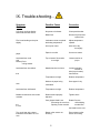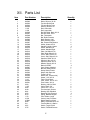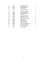
1
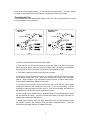
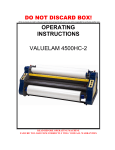
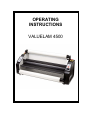
OPERATING
INSTRUCTIONS
VALUELAM 4500
READ BEFORE OPERATING
CAUTION...
TO AVOID ANY DAMAGE,
PLEASE
DO NOT USE RAZORS OR
SHARP
OBJECTS NEAR THE ROLLERS.
DO NOT LEAVE MACHINE ON
WHEN NOT IN USE OR YOU WILL
DAMAGE YOUR ROLLERS!
2
Table of Contents
I.
For Your Safety...................................... 4
II.
Electrical Safeguards ............................. 4-5
III.
Specifications......................................... 5
IV.
Set-up .................................................... 5-8
Inspection............................................... 5
Appropriate Location.............................. 5
Loading Film onto Mandrels................... 6
Film Tension .......................................... 6-7
Threading the Film ................................. 7-8
V.
Thermal Laminating ............................... 9-10
VI.
Coating Mount Board ............................. 10
VII.
Mounting & Laminating .......................... 10-11
VIII. Maintenance/Service ............................. 11
Cleaning Rubber Rollers........................ 11-12
Removing Wrap-arounds ....................... 12
IX.
Trouble-shooting .................................... 13
X.
Laminating & Mounting Do’s & Don’ts .. 14
XI.
Warranty & Return Policy....................... 14
XII.
Parts List ............................................ 15-16
3
OPERATING INSTRUCTIONS
VALUELAM 4500
I. For your safety...
Do not connect the laminator to electrical power or attempt to operate it until
you have read these instructions completely. Keep these instructions in a
convenient location for future reference.
Read all safety messages located in this instruction manual and on the
laminator very carefully.
Always lower the safety shield before operating your laminator.
Removing feed table exposes hot and moving parts. This means that you can
be harmed if you remove the feed table. When the table is in the proper
position the risk of injury to the operator is reduced.
Do not operate this laminator without all detachable units installed correctly.
This means that there is risk of injury if this product is operated without all of its
parts in their proper positions.
Keep hands and clothing away from rollers. The rollers are pinch points that
can trap body parts or clothing and cause serious injury.
Do not touch the rollers while the laminator heater power is on. Turn
rollers off and allow to cool.
Do not use the laminator for other than its intended purpose.
II. Electrical Safeguards...
Never override or attempt to defeat electrical or mechanical safety interlock
devices.
The machine has been manufactured with a plug on the machine designed to
operate on a 110volt, 20 Ampere circuit.
Disconnect power supply before servicing your laminator.
The laminator should only be operated from the type of power source indicated
in these OPERATING INSTRUCTIONS and on the serial label located on the
rear panel of the unit.
4
Do not leave the laminator power on for extended periods while not in use.
Unplug the machine at the end of the day as a precaution against a possible
fire hazard.
Do not operate the laminator with a damaged power supply cord or plug.
Replace fuses only with same type rated 20, 250V and 1A, 250V fuses.
Contact your dealer for replacement fuses.
There are two (2) EMERGENCY STOP buttons on the laminator, one on each
side. Depressing one of these buttons will stop the rollers.
III. Specifications...
Operating Speed:
Adjustable to 5 fpm (2.54cm/sec.)
Power Requirements
Voltage:
108-125 VAC, 50/60 hz
Warm Up Time:
Power Fuse:
Motor fuse:
25-30 minutes
20 A
1A
Maximum Laminating Dimensions
Thickness:
Width Capacity:
¼” (6.35mm)
45” (1143mm)
Net Weight:
Shipping Weight:
183 lbs
383 lbs
IV. Set-up...
Inspection:
Upon receipt of your ValueLam 4500, inspect the crate, the machine and all other contents of
the crate for shipping damage. Damage should be brought to the immediate attention of the
delivering carrier.
Power Requirements:
The ValueLam 4500 is designed to operate on a 110 Volt, 20 Ampere circuit. It will plug into a
standard 110 volt wall receptacle. You must ensure that the circuit is protected by a 20 Amp
circuit breaker.
Appropriate Location:
The laminator must be placed on a sturdy table or stand in a clean, well lit area with ample
space on all four sides of the laminator.
5
Loading Film onto Mandrels:
When the film is loaded properly the core gripper blade will prevent the film from turning on the
supply mandrel. With the gripper spring away from you, pull the core gripper blade toward you
and place the roll of film onto the mandrel. Turn the roll on the mandrel to lock the core gripper
blade into the cardboard film core.
Supply Mandrel Orientation:
The supply mandrels must be placed on the machine in the proper orientation to achieve film
tension. (Note the position of the core grippers in the illustration as viewed from the right hand
end).
Top Roll, Poly (adhesive) In: With the gripper spring away from you, pull the core gripper
blade toward you and place the roll of film onto the mandrel so that the film unwinds towards
you from the bottom of the roll. Turn the roll on the mandrel to lock the core gripper blade into
the cardboard film core.
Bottom Roll, Poly (adhesive) In: With the gripper spring towards you, push the core
gripper blade away from you and place the roll of film onto the mandrel so that the film unwinds
away from you from the bottom of the roll. Turn the roll on the mandrel to lock the core gripper
blade into the cardboard film core.
The core gripper blades on the top and bottom mandrels spring back in opposite directions.
The blade should spring back in the direction that the core will rotate when laminating. When
the film is loaded properly the core gripper blade will prevent the film from turning on the
mandrel. When using poly-in rolls the top roll of film should unwind from the bottom of the roll
and the bottom of the roll should also unwind from the bottom of the roll. With Poly-out rolls the
top roll will unwind from the top and the bottom roll will also unwind from the top of the roll.
Once the film is properly loaded onto the mandrels, replace the mandrels onto the laminator.
Film Tension:
Film tension must be set correctly to ensure good lamination quality. At each end of the film
supply roll mandrels there is a split Delrin® brake bushing. When the supply mandrel is placed
into the holders, the split of the brake bushing must be up. To adjust film tension, turn the
6
thumb screws in the mandrel holders. Turn clockwise to increase tension. This action clamps
the brake on the mandrel axle creating tension necessary to achieve good results.
Threading the Film:
Your ValueLam 4500 was delivered with sample rolls of film. When changing film rolls, thread
the film according to the instructions.
1. Remove the feed table and raise the safety shield.
2. Feed the film from the top roll under the upper idler roller, over the top roller and
behind the safety shield, and pull it down below both rollers. Be sure that the adhesive
side of the film is facing out and the non-adhesive side is against the roller
3. To thread the lower roll, first drop the lower idler roll down.
4. Pull about 3 feet of film from the bottom roll. Feed the film from the bottom roll under
and behind the lower idler roller. Now raise the lower idler roller to the lamination
position. Align the edges of top and bottoms rolls so there is no side to side overlap.
This will prevent transferring adhesive to the roller.
5. Lay the film from the lower roll over the film from the top roll and both rollers, again
ensuring the adhesive side is away from the rollers. If you are cold loading, it will be
necessary to tape the bottom film to the top film. If you are hot loading, the bottom film
will adhere to the top film where they overlap at the rollers.
6. Have a large piece of poster board or cardboard ready to use as a feed card to thread
the film between the rollers. A piece 6-8 inches wide and the full width of the film will
help prevent wrinkles when loading hot.
7. Replace the feed table, lower the safety shield and move the roller pressure arm to
the “MOUNT” position and install the pins (see Roller Position/Pressure). Place the
board on the feed table and push it forward to the roller.
7
8. Turn the SPEED CONTROL knob far enough to allow the rollers to sufficiently pull the
poster board or cardboard into the laminator. Keep in mind that varying media and
temperatures will require different speeds.
9. Feed the poster board or cardboard between the rollers.
10. If you are loading cold, allow the poster board or cardboard to continue through
completely with the ends of both films. You may now raise the rollers to the open
position to facilitate aligning the film and remove any wrinkles.
11. If you are hot loading, stop the motor after the poster board or cardboard has
traveled one or two inches through the rollers. Move the roller pressure adjustment arm
to the “STD Lam” position and install the pins. Now apply tension to the film and run the
motor slowly. This procedure will help prevent the formation of wrinkles. After the board
has passed through the rollers and there are no wrinkles, reduce the film tension to the
minimum amount needed.
Roller Position/Pressure:
The roller position and pressure is determined by placement of pins into the red roller pressure
adjustment arm through the proper holes in the side plate. These three holes and pins are
located at the rear of the machine below the rear run off table. When the pins are installed
properly, the red roller pressure adjustment arm cannot be raised or lowered.
Open - The top hole is the “OPEN” position. When both side pins are removed, lift the red
roller pressure adjustment arm to the “OPEN” position as indicated on the cover label and insert
the pins into the top hole. The pins must be removed from both sides before attempting to
move the roller to the OPEN position.
Mount - When both side pins are removed, the roller falls to the “MOUNT” position and the
red roller pressure adjustment arm aligns with “MOUNT” on the label. When mounting onto
3/16” or 1/4” board, the pins should be placed in the middle, “Mount” hole.
Standard Laminating - All regular lamination should be done with the pins in the “STD
Lam” position. When both side pins are removed, press down on the pressure adjustment arm
and align with “STD Lam” on the label. The pins should now be placed in the bottom hole.
8
V. Thermal Laminating...
1. Be sure all laminator parts (i.e. safety shield, feed table, etc.) are in their proper positions
and the laminating film is loaded correctly.
2. Set the temperatures according to the film manufacturer’s recommendations for the film
you have chosen. A low-melt film is recommended for inkjet prints. Keep in mind that the
temperature at which you will laminate will vary with different medias and laminating
speeds. See the chart below for approximate temperature ranges. The laminator will take
approximately 25-30 minutes to reach operating temperature. The temperatures will be
indicated on the LCD display.
3 mil DIGIKOTE™
5 mil DIGIKOTE™
10 mil DIGIKOTE™
190°-210°F
220°-230°F
225°-235°F
3. Your new ValueLam 4500 has a digital heat controller. Users can easily adjust the set
temperature to achieve the best quality lamination. The controller has been calibrated to
accurately display the roller temperature in the laminating range.
The heater switch on the right side frame activates the controller. When the switch is turned
on the controller will flash a two letter code and then display the current roller temperature.
When cold, the temperature displayed on the controllers may be different than the actual
ambient temperature to account for correction in the higher temperature range. When the
heater switch is turned on the controller will send power to the heaters, provided the set
temperature is higher than ambient temperature.
When power is being sent to the heaters the controller will illuminate a small red indicator
light in the lower right hand corner of the display. The light goes out when the set
temperature is reached. Power to the heaters cycles on and off when the roller temperature
falls below set temperature during lamination.
4. To determine the set temperature, with the heater switch activated and the current
temperature displayed, press and hold down either the up or down arrow for 3-4 seconds.
The display will change and flash the set temperature and “SU” alternately. After 10
seconds the display will return to the current roller temperature.
To change the set temperature, depress and hold either arrow down for 3-4 seconds until
the set temperature and “SU” flash. Depress and hold the appropriate arrow to raise or
lower the setting. The digits will change slowly initially but will increase speed when held
down longer for large changes. When the desired setting has been reached, depress both
arrows simultaneously to save the Set Temperature.
Each time the machine is turned on it will heat up to the last set temperature. It is advisable
to verify the set temperature when starting to warm up the machine each day.
5. Turn the MOTOR switch ON and perform a test lamination to ensure proper settings for
successful lamination. Watch film as it exits the rollers so it doesn’t wrap around the
rollers. It might be helpful to hold the film at first when starting a lamination run. If any
adjustments are necessary make them now and run another test. Repeat this step until
you obtain desired results.
9
6. Allow the ValueLam 4500 to run a small amount of film before feeding the print into the
laminator to avoid a dwell line across your print. Feed the print slowly and evenly,
smoothing it as the rollers pull it through.
7. You may laminate subsequent prints now, leaving ample space between each print for
trimming.
8. Once your last print has completely exited the laminator, turn the MOTOR switch OFF.
9.When you have finished laminating, turn heat switch off and pull out the roller pressure pins
to release the pressure on the rollers. This will eliminate the chance of “flat spotting” the
rollers.
VI. Coating Mount Board...
The ValueLam 4500 is capable of applying an adhesive coating to mount board that has not
previous been coated.
1. Load a roll of adhesive, with the liner wound to the outside, onto the top mandrel in the
same manner as with laminating film.
2. Load a roll of paper on the bottom mandrel or use adhesive the same width as the mount
board to keep the adhesive from accumulating on the rollers.
3. Set the temperature to approximately 125°F. The ValueLam 4500 will take approximately
10-15 minutes to reach operating temperature. The roller temperatures are indicated on
the LCD displays.
4. Feed the uncoated mount board into the laminator behind a small leader board. The
leader board will prevent the compression of the leading edge of your mount board.
5. You may coat subsequent boards now, one directly behind the other, so that the board in
front becomes the leader board. We recommend that you coat a sufficient supply of mount
board in one session so you’ll have it ready for future use.
VII. Mounting & Laminating...
1. Be sure all laminator parts (i.e. safety shield, feed table, etc.) are in their proper positions
and the laminating film is loaded correctly.
2. Place mounting pins in proper “mount” holes.
3. Turn the TEMPERATURE CONTROL switch to the ON position.
4. Set the temperatures according to the film manufacturer’s recommendations for the film
you have chosen. The ValueLam 4500 will take approximately 10-15 minutes to reach
operating temperature. The temperatures of the heated rollers are indicated on the LCD
display.
10
5. Turn the MOTOR switch ON and perform a test mount to ensure proper settings for
successful mounting. If any adjustments are necessary make them now and run another
test. Repeat this step until you obtain desired results.
6. Position the print to be mounted on a section of mount board up to ¼” thick behind a
leader board. The leader board will prevent compression of the leading edge of your mount
board.
7. Peel the release liner from the board back about ¼” thick behind a leader board if
necessary unless your mount board is larger than your print and you will be trimming your
board afterwards. A leader board will prevent compression on the leading edge of your
mount board.
8. Feed the print and mount board into the laminator behind the leader board slowly and
evenly. Be sure to pull back the release liner before it enters the rollers.
9. You may mount subsequent prints now, one directly behind the other so that the board in
front becomes the leader board.
10. Once your last print has completely exited the laminator, turn the MOTOR switch OFF
and use a razor to remove the mounted and laminated prints.
VIII. Maintenance/Service...
Always use caution when servicing your laminator.
Precautions:
Disconnect the power supply and open the panel breaker
before attempting to service or repair the laminator.
Any maintenance or service should be preformed only by those
having appropriate technical training and experience. Contact
Banner American Products at 800 572-2144 for technical assistance.
Adjust only those controls that are specified in these
operating instructions.
11
Cleaning Rubber Rollers:
Excessive build-up of adhesive on the rollers may cause poor lamination quality and erratic film
movement. Use the following procedure to remove any adhesive from the laminating rollers.
1. Turn the HEATED ROLLERS off and allow the laminator to cool.
2. Cut the film where it comes off the top and bottom supply rolls. Pull any film out of the
laminator and away from the rollers.
3. Carefully remove the feed table to access the rollers. The feed table exposes hot and
moving parts.
4. Disconnect the power supply.
5. Clean the exposed section of the rollers with a soft cloth dampened with an appropriate
cleaning solution such as denatured alcohol.
6. Reconnect the power supply and turn the FORWARD/REVERSE switch to the
FORWARD position. Turn the MOTOR switch to the ON position momentarily to expose
a new section of the rollers.
7. Repeat steps 3-5 until the rollers are thoroughly clean.
8. Allow the rollers to dry completely before rethreading the laminating film.
Removing Wrap-A-Rounds:
Build-up on the rollers may cause a film wrap-around, especially when using thin film gauges.
Follow the procedure below to remove wrap-a-rounds.
1. Turn the HEATED ROLLERS OFF. Allow the laminator to cool.
2. Cut the film where it comes off the top and bottom supply rolls.
3. Raise the roller pressure adjustment arms to the open position and insert pins on the
side of the laminator and pull the film out of the unit that has become wrapped around
the rollers.
4. If you have a severe wrap-around, it may be necessary to use the REVERSE feature
to back the film out. Be sure to pull the film away from the laminator.
If there is a wrap-around on the lower roller, of if there is a run-away heat condition;
please check the sensor on the bottom roller to ensure it is touching the roller. Incorrect
positioning of the sensor can result in a false roller temperature reading and subsequent
roller damage.
12
IX. Trouble-shooting...
Symptom
Action
Possible Cause
Corrective
LCD does not show display
when heat switches are on.
No power to laminator
Close panel breaker
Blown fuse
Disconnect power and
replace fuse
Laminator not set to optimal
laminating temperature
Adjust temperature
upward.
Ink on print is wet
Allow ink to dry
thoroughly
Paper is too slick
Use a more matte
Laminated item curls
side
bottom) film is
curling toward.
Top or bottom film tension
is too high.
Loosen tension on
(top or
Laminated item is wrinkled
Mandrel tension too loose
Increase mandrel
tension on
side (top or bottom)
has wrinkles
Temperature too high
Reduce temperature
Moisture in paper being
Store paper in dry
Film is not bonding to the print
slightly
paper
that
area
Laminated.
Laminated item is blistered
Temperature too high
Reduce temperature
Mandrel tension does not remain
constant
Brake screw improperly
adjusted
Tighten screw
the
to lock
Core gripper blade is not
Rotate film core
preventing the core from
while holding
spinning on the mandrel
mandrel firm
the blade into the core
Too much heat with a lower
Indicated heat readout on LCD
core.
Bottom roller sensor not
touching
13
Ensure bottom roller
sensor is touching
X. Do’s and Don’ts...
•
Read the instruction manual before operating your laminator.
•
Always run test samples before laminating valuable items.
•
•
Feed the print through slowly and evenly, smoothing it as it is pulled into the
laminator.
•
Operate the laminator with two rolls of the same width laminating film to avoid
excessive adhesive transfer to the rollers.
•
If laminator is not in current use, lower the heat setting or turn unit off.
•
Never feed abrasive materials or metal objects such as staples, paper clips, or
glitter
through the laminator. Keep sharp objects like scissors and rulers away from the
rollers at all times.
•
•
Once an item has been fed between the rollers do not attempt to alter its position
as this can damage the print.
•
Do not stop the laminator before the item has completely exited from the rear to
avoid a “dwell line” across the print.
•
Do not clean or service the laminator before disconnecting the power supply.
XI. Warranty & Return Policy...
Warranty:
Your ValueLam 4500 is warranted to be free of defects in material and workmanship for a
period of 1 year from the date of original purchase. In the event of a defect in materials or
workmanship, Banner American Products, Inc. will, at their option, repair or replace the
laminator.
Banner American Products, Inc. makes no other warranty stated or implied except as stated
above. This warranty does not cover damage to the machine that occurs as a result of misuse
or improper handling, or damage to prints.
Return Policy:
If your laminator is not operating properly, first review the Operating Instructions and the
troubleshooting guide. If the malfunction cannot be corrected, contact Banner American for
instructions. Be sure to have your machine serial number and date of purchase handy.
If the laminator must be returned to the dealer, it is your responsibility to ensure that it is
packaged properly. Shipping damage as a result of improper packaging is not covered under
the terms of this warranty.
14
XII. Parts List
Item
1
2
3
4
5
6
7
8
9
10
11
12
13
14
15
16
17
18
19
20
21
22
23
24
25
26
27
28
29
30
31
32
33
34
35
36
37
38
39
40
41
42
43
44
45
46
47
48
49
50
Part Number
Description
645003
645033
645032
645034
11125
11126
645026
645027
645048
645004
645005
645006
645007
645008
645009
645010
645011
645012
645013
645014
645015
645016
645017
645018
645019
643557
645047
645020
645021
645022
645023
645024
645025
11111
645030
645031
2369
11187
4268
8149
8381
2870
8274
1170
10124
LCD48
8288
541
2351
2775
Roller, Silicone, 35-40
Top Idler Roller Rod
Top Idler Roller Tube
Housing, Rod 45110
Rod, Lower Idler
Rod, Lower Idler
Run-Off Table, Back 45110
Run-Off Table, Front
Bar, Thermostat
Bar, Roller Pressure
Block, Bearing, Left
Block, Bearing, Right
Bar, Pressure Adjustment
Holder, Heater 45110
Standoff, Holder, Heater
Holder, Mandrel Left
Holder, Mandrel Right
Plate, Left Side 45110
Plate, Right Side 45110
Cover, Side, Left 45110
Cover, Side, Right 45110
Sprocket, Roller 45110
Sprocket, Idler, 45110
Sprocket, Motor 45110
Mandrel, Supply 45110
Brake for EN45
Core Gripper, Mandrel
Bracket, Safety Shield
Safety Shield, Plastic
Mount, Idler Sprocket
Tie Bar, 45110
Mount, Bar, Pressure Adj.
Heater, 110V 45110
Table, Feed, Black
Cord, Power, 45110 12/3
Fuse Holder, 45110
Bushing, Idler for RL43
Collar, Shaft, 5/8”
Collar, Set, 1.25 I.D.
Thermocouple, Sensor
Bearing, Ball, Shielded
Retaining Ring, External
Spring, Mandrel Gripper
Feet, Rubber, Large
Control, Heat, Finishers
Digital Read Out (New)
Relay, Solid State 25A DC
Terminal Block, 6 Station
Switch, Toggle, RL40
Switch, Forward/Reverse
15
Quantity
2
1
1
1
1
1
1
1
1
2
1
1
2
4
4
2
2
1
1
1
1
2
1
1
2
4
2
1
1
2
2
2
2
1
1
1
4
2
2
1
4
4
2
4
1
1
1
2
1
1
51
52
53
54
55
6546
10085
11045
10398
2325
Switch, Emergency Stop
Motor, EZII, 80mm
Variable Speed Control
Chain, #35 Bulk
Chain, Link, #35 Master
2
1
1
2
1
56
57
58
59
60
61
62
63
64
65
66
67
68
69
70
71
72
73
74
1172
11480
645040
645039
645041
11559
11560
11561
11571
645046
2777
645042
645043
11579
SR43-5
2664
2665
11586
7310
Fuse Holder, HTB-34I
On/Off Switch 25A DP 43
Pin, Roller Adjustment
Spring, Roller Pressure
Lift Bar 45110
3/16-24 X 1” Lg Eyebolt
Thumb Screw, 10-24 X
Shim, Roller, 1 ¼ ID X
Plug, Power, 15A 125V Ace
Washer, Phenolic #10 Flat
Switch, Journal
wm1329-nd Plug
wm1336-nd Receptacle
Crate, Wide Format
43” x 50’ 5 mil ValueLam 4500
Power connector, male
Power connector, female
Fuse, 20 amp FNQ-20
Fuse, 1A (MDL)
1
1
2
2
2
2
2
4
1
4
2
1
1
1
2
1
1
1
1
16