1
Cisco 800 Series Integrated Services Routers Software Configuration
Guide
First Published: January 01, 2009
Last Modified: July 22, 2014
Americas Headquarters
Cisco Systems, Inc.
170 West Tasman Drive
San Jose, CA 95134-1706
USA
http://www.cisco.com
Tel: 408 526-4000
800 553-NETS (6387)
Fax: 408 527-0883
Text Part Number: OL-31704-02
© 2009-14
Cisco Systems, Inc. All rights reserved.
CONTENTS
Preface
Preface xxiii
Audience xxiii
Document Organization xxiii
Document Conventions xxv
Related Documentation xxvi
Obtaining Documentation and Submitting a Service Request xxvii
CHAPTER 1
Product Overview 1
Information About Cisco 800 Series ISRs 1
Cisco 860 Series ISRs 1
Features of Cisco 860 Series ISRs 2
4-port 10/100 FE LAN Switch of Cisco 860 Series ISRs 2
Security Features for Cisco 860 Series ISRs 2
802.11n Wireless LAN Option for Cisco 860 Series ISRs 2
Features of Cisco 860VAE Series ISRs 2
General Features of Cisco 860 VAE Series Routers 2
Interfaces of Cisco 860 VAE Series ISRs 4
IOS Images for Cisco 860 VAE Series ISRs 5
Cisco 880 Series ISRs 5
Models of Cisco 880 Series ISRs 5
Common Features of Cisco 880 Series ISRs 7
4-port 10/100 FE LAN Switch of Cisco 880 Series ISRs 7
802.11n Wireless LAN Option of Cisco 880 Series ISRs 7
Real-Time Clock of Cisco 880 Series ISRs 7
Security Features of Cisco 880 Series ISRs 8
Voice Features of Cisco 880 Series ISRs 8
Cisco 890 Series ISRs 8
Cisco 800 Series Integrated Services Routers Software Configuration Guide
OL-31704-02
iii
Contents
8-port 10/100 FE LAN Switch of Cisco 890 Series ISRs 9
802.11n Wireless LAN Option of Cisco 890 Series ISRs 9
Real-Time Clock of Cisco 890 Series ISRs 9
Security Features of Cisco 890 Series ISRs 9
Cisco 810 Series ISRs 10
Features of Cisco 812 Series ISRs 10
3G Features of Cisco 812 Series ISR 10
WLAN Features of Cisco 812 Series ISR 11
Dual Radio of Cisco 812 Series ISR 11
Cleanair Technology of Cisco 812 Series ISR 11
Dynamic Frequency Selection of Cisco 812 Series ISR 11
Platform Features of Cisco 812 Series ISR 11
TFTP with Ethernet WAN Interface Feature of Cisco 812 Series ISR 12
SKU Information for Cisco 812 Series ISR 12
Features of Cisco 819 Series ISRs 12
3G Features of Cisco 819 Series ISRs 12
WLAN Features of Cisco 819 Series ISRs 13
4G LTE Features of Cisco 819 Series ISRs 13
Platform Features of Cisco 819 Series ISRs 13
Security Features of Cisco 819 Series ISRs 13
SKU Information for Cisco 819 Series ISRs 14
Licensing for Cisco 800 Series ISRs 14
Selecting Feature Sets for Cisco 800 Series ISRs 14
CHAPTER 2
Basic Router Configuration 15
Interface Ports 15
Default Configuration 16
Information Needed for Configuration 17
Configuring Command-Line Access 19
Configuring Global Parameters 21
Configuring WAN Interfaces 22
Configuring a Gigabit Ethernet WAN Interface 22
Configuring the Cellular Wireless WAN Interface 23
Prerequisites for Configuring the 3G Wireless Interface 24
Restrictions for Configuring the Cellular Wireless Interface 24
Cisco 800 Series Integrated Services Routers Software Configuration Guide
iv
OL-31704-02
Contents
Data Account Provisioning 25
Verifying Signal Strength and Service Availability 25
Configuring a GSM Modem Data Profile 26
CDMA Modem Activation and Provisioning 27
Configuring a Cellular Interface 29
Configuring DDR 31
Examples for Configuring Cellular Wireless Interfaces 33
Basic Cellular Interface Configuration 34
Tunnel over Cellular Interface Configuration 34
Configuration for 8705 modem 35
Configuring Dual SIM for Cellular Networks 35
Configuring Router for Image and Config Recovery Using Push Button 37
Output When Button Is Not Pushed: Example 38
Output When Button Is Pushed: Example 38
Push Button in WLAN AP 39
Configuring the Fast Ethernet LAN Interfaces 39
Configuring a Loopback Interface 39
Configuring Static Routes 41
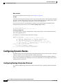
Configuring Dynamic Routes 42
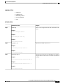
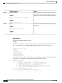
Configuring Routing Information Protocol 42
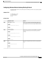
Configuring Enhanced Interior Gateway Routing Protocol 45
CHAPTER 3
Configuring Ethernet CFM and Y.1731 Performance Monitoring on Layer 3 Interfaces 47
Configuring a Network Interface Device on the L3 Interface 47
Configuring the NID 47
Configuration Example 49
Verifying the NID Configuration 49
Troubleshooting the NID Configuration 50
Ethernet Data Plane Loopback 50
Restrictions for Configuring Ethernet Data Plane Loopback 51
Configuring External Ethernet Data Plane Loopback 52
Configuration Examples for Ethernet Data Plane Loopback 54
Verifying the Ethernet Data Plane Loopback Configuration 54
Troubleshooting the Ethernet Data Plane Loopback Configuration 55
CFM Support on Routed Port and Port MEP 56
Cisco 800 Series Integrated Services Routers Software Configuration Guide
OL-31704-02
v
Contents
Restrictions for Configuring Ethernet CFM 56
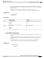
Configuring Ethernet CFM (Port MEP) 57
Configuration Example for Ethernet CFM (Port MEP) 59
Verifying the Ethernet CFM Configuration on a Port MEP 59
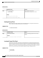
Configuring Ethernet CFM (Single-Tagged Packets) 61
Configuration Example for Ethernet CFM (Single-Tagged Packets) 63
Verifying the Ethernet CFM Configuration for Single-Tagged Packets 63
Configuring Ethernet CFM (Double-Tagged Packets) 65
Configuration Example for Ethernet CFM (Double-Tagged Packets) 68
Verififying the Ethernet CFM Configuration for Double-Tagged Packets 68
Troubleshooting Ethernet CFM Configuration 70
Support for Y.1731 Performance Monitoring on Routed Port (L3 Subinterface) 71
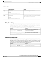
Frame Delay 71
Restrictions for Configuring Two-Way Delay Measurement 71
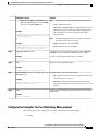
Configuring Two-Way Delay Measurement 72
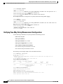
Configuration Examples for Two-Way Delay Measurement 73
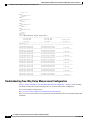
Verifying Two-Way Delay Measurement Configuration 74
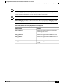
Troubleshooting Two-Way Delay Measurement Configuration 76
CHAPTER 4
Configuring Power Management 79
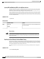
Monitoring Power Usage with EnergyWise 79
Configuring Power-over-Ethernet 79
Enabling/Disabling Power-over-Ethernet 79
Verifying the Power-over-Ethernet Configuration on the Interface 80
CHAPTER 5
Configuring Security Features 81
Authentication, Authorization, and Accounting 81
Configuring AutoSecure 82
Configuring Access Lists 82
Access Groups 83
Configuring Cisco IOS Firewall 83
Configuring Cisco IOS IPS 84
URL Filtering 84
Configuring VPN 85
Configuring a VPN over an IPSec Tunnel 87
Cisco 800 Series Integrated Services Routers Software Configuration Guide
vi
OL-31704-02
Contents
Configuring the IKE Policy 87
Configuring Group Policy Information 89
Applying Mode Configuration to the Crypto Map 90
Enabling Policy Lookup 90
Configuring IPSec Transforms and Protocols 91
Configuring the IPSec Crypto Method and Parameters 92
Applying the Crypto Map to the Physical Interface 93
Creating a Cisco Easy VPN Remote Configuration 94
Configuring a Site-to-Site GRE Tunnel 97
CHAPTER 6
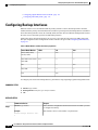
Configuring Backup Data Lines and Remote Management 101
Configuring Backup Interfaces 102
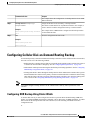
Configuring Cellular Dial-on-Demand Routing Backup 103
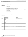
Configuring DDR Backup Using Dialer Watch 103
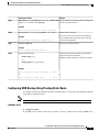
Configuring DDR Backup Using Floating Static Route 105
Cellular Wireless Modem as Backup with NAT and IPsec Configuration 106
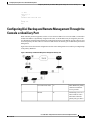
Configuring Dial Backup and Remote Management Through the Console or Auxiliary Port 109
Example for specifying an IP address for the ATM interface through PPP and IPCP address
negotiation and dial backup 113
Configuring Data Line Backup and Remote Management Through the ISDN S/T Port 115
Configuring ISDN Settings 118
Configuring Aggregator and ISDN Peer Router 120
Configuring Gigabit Ethernet Failover Media 121
Configuring Auto-Detect 122
Configuring Third-Party SFPs 123
Example for Configuring Third-Party SFPs 126
CHAPTER 7
Configuring Ethernet Switches 127
Switch Port Numbering and Naming 127
Restrictions for the FE Switch 128
Ethernet Switches 128
VLANs and VLAN Trunk Protocol 128
Inline Power 128
Layer 2 Ethernet Switching 128
802.1x Authentication 128
Cisco 800 Series Integrated Services Routers Software Configuration Guide
OL-31704-02
vii
Contents
Spanning Tree Protocol 129
Cisco Discovery Protocol 129
Switched Port Analyzer 129
IGMP Snooping 129
Storm Control 130
Overview of SNMP MIBs 130
BRIDGE-MIB for Layer 2 Ethernet Switching 130
MAC Address Notification 131
Configuring Ethernet Switches 131
Configuring VLANs 132
VLANs on the FE and GE Switch Ports 132
VLANs on the GE Port and GE ESW Port of Wireless APs 133
Configuring Layer 2 Interfaces 134
Configuring 802.1x Authentication 134
Configuring Spanning Tree Protocol 134
Configuring MAC Table Manipulation 135
Configuring Cisco Discovery Protocol 135
Configuring the Switched Port Analyzer 136
Configuring Power Management on the Interface 136
Configuring IP Multicast Layer 3 Switching 136
Configuring IGMP Snooping 136
Configuring Per-Port Storm Control 137
Configuring Separate Voice and Data Subnets 137
Managing the Switch 137
CHAPTER 8
Configuring Voice Functionality 139
Voice Ports 139
Analog and Digital Voice Port Assignments 140
Voice Port Configuration 140
Call Control Protocols 140
SIP 140
MGCP 141
H.323 141
Dial Peer Configuration 141
Other Voice Features 141
Cisco 800 Series Integrated Services Routers Software Configuration Guide
viii
OL-31704-02
Contents
Real-Time Transport Protocols 141
Dual Tone Multi Frequency Relay 142
CODECs 142
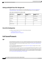
SCCP-Controlled Analog Ports with Supplementary Features 142
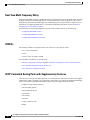
Fax Services 143
Fax Pass-Through 143
Cisco Fax Relay 143
T.37 Store-and-Forward Fax 143
T.38 Fax Relay 143
Unified Survival Remote Site Telephony 143
Verification of Voice Configuration 144
CHAPTER 9
Configuring the Serial Interface 145
Configuring the Serial Interface 145
Legacy Protocol Transport 146
Configuring Serial Interfaces 147
Cisco HDLC Encapsulation 147
PPP Encapsulation 147
Multilink PPP 148
Keepalive Timer 149
Frame Relay Encapsulation 149
LMI on Frame Relay Interfaces 150
Configuring Serial Interfaces 150
Configuring a Synchronous Serial Interface 151
Specifying a Synchronous Serial Interface 151
Specifying Synchronous Serial Encapsulation 151
Configuring PPP 152
Configuring Bisync 152
Configuring Compression of HDLC Data 152
Using the NRZI Line-Coding Format 153
Enabling the Internal Clock 154
Inverting the Transmit Clock Signal 154
Setting Transmit Delay 155
Configuring DTR Signal Pulsing 155
Ignoring DCD and Monitoring DSR as Line Up/Down Indicator 156
Cisco 800 Series Integrated Services Routers Software Configuration Guide
OL-31704-02
ix
Contents
Specifying the Serial Network Interface Module Timing 156
Specifying the Serial Network Interface Module Timing 157
Configuring Low-Speed Serial Interfaces 157
Half-Duplex DTE and DCE State Machines 157
Half-Duplex DTE State Machines 158
Half-Duplex DCE State Machines 159
Placing a Low-Speed Serial Interface in Constant-Carrier Mode 161
Tuning Half-Duplex Timers 162
Changing Between Synchronous and Asynchronous Modes 162
Changing Between Synchronous and Asynchronous Modes 163
Examples for Interface Enablement Configuration 164
Examples for Low-Speed Serial Interface 164
Examples for Synchronous or Asynchronous Mode 164
Example for Half-Duplex Timers 165
CHAPTER 10
Configuring Wireless Devices 167
Wireless Device Overview 167
Software Modes for Wireless Devices 167
Management Options for Wirelss Device 168
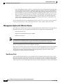
Root Access Point 168
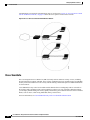
Central Unit in an All-Wireless Network 169
Cisco ScanSafe 170
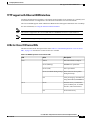
TFTP support with Ethernet WAN interface 171
LEDs for Cisco 819 Series ISRs 171
Basic Wireless Configuration for Cisco 800 Series ISR 174
Starting a Wireless Configuration Session 174
Closing the Session 176
Configuring Wireless Settings 177
Cisco Express Setup 177
Cisco IOS Command Line Interface 177
Configuring the Radio 177
Configuring Wireless Security Settings 178
Configuring Authentication 178
Configuring WEP and Cipher Suites 178
Configuring Wireless VLANs and Assigning SSIDs 179
Cisco 800 Series Integrated Services Routers Software Configuration Guide
x
OL-31704-02
Contents
Configuring Wireless Quality of Service 181
Configuring the Access Point in Hot Standby Mode 181
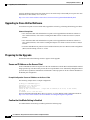
Upgrading to Cisco Unified Software 182
Preparing for the Upgrade 182
Secure an IP Address on the Access Point 182
Example Configuration: Secure an IP Address on the Access Point 182
Confirm that the Mode Setting is Enabled 182
Performing the Upgrade 183
Troubleshooting an Upgrade or Reverting the AP to Autonomous Mode 183
Downgrading the Software on the Access Point 184
Recovering Software on the Access Point 184
Related Documentation 184
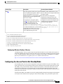
Configuring Radio Settings 186
Enabling the Radio Interface 186
Wireless Device Roles in a Radio Network 187
Configuring the Wireless Device Roles in a Radio Network 188
Configuring Dual-Radio Fallback 189
Radio Tracking 189
Fast Ethernet Tracking 189
MAC-Address Tracking 190
Overview of Radio Data Rates 190
Configuring Radio Data Rates 191
Configuration Example: Configuring Radio Data Rates 193
Configuring MCS Rates 193
Configuration Example: MCS Rates 195
Configuring Radio Transmit Power 195
Limiting the Power Level for Associated Client Devices 196
Configuring Radio Channel Settings 197
Configuring Wireless Channel Width 198
Enabling and Disabling World Mode 199
Enabling World Mode 199
Disabling and Enabling Short Radio Preambles 200
Disabling Short Radio Preambles 200
Transmit and Receive Antennas 201
Configuring Transmit and Recieve Antennas 201
Cisco 800 Series Integrated Services Routers Software Configuration Guide
OL-31704-02
xi
Contents
Disabling and Enabling Aironet Extensions 202
Disabling Aironet Extensions 203
Ethernet Encapsulation Transformation Method 204
Configuring the Ethernet Encapsulation Transformation Method 204
Enabling and Disabling Public Secure Packet Forwarding 205
Configuring Public Secure Packet Forwarding 205
Configuring Protected Ports 206
Beacon Period and the DTIM 207
Configuring the Beacon Period and the DTIM 207
RTS Threshold and Retries 208
Configuring RTS Threshold and Retries 208
Maximum Data Retries 209
Configuring the Maximum Data Retries 209
Configuring the Fragmentation Threshold 210
Configuring the Fragment Threshold 210
Enabling Short Slot Time for 802.11g Radios 211
Performing a Carrier Busy Test 211
Configuring VoIP Packet Handling 211
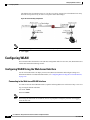
Configuring WLAN 212
Configuring WLAN Using the Web-based Interface 212
Connecting to the Web-based WLAN Interface 212
Address for Accessing Web-based Interface 213
DHCP Server Configuration 213
Subnet 213
Displaying Device Information 213
Displaying Connection Statistics 213
Configuring Access to the Web-based Interface 213
Configuring Basic Wireless Settings 214
Configuring Security 215
Configuring MAC Filtering 215
Configuring Advanced Wireless Settings 215
Station Information 218
Configuring the Password for Connecting to the Web-based Interface 218
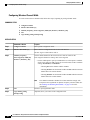
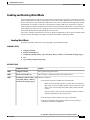
Saving the Wireless LAN Configuration to a File 219
Loading a Wireless LAN Configuration File 219
Cisco 800 Series Integrated Services Routers Software Configuration Guide
xii
OL-31704-02
Contents
Restoring the Default Configuration 219
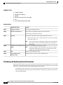
Configuring WLAN Using the CLI-based Interface 219
WLAN CLI Interface 219
Displaying Command Information for WLAN CLI 220
Example : Displaying Command Information for WLAN CLI 220
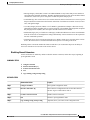
Connecting to the WLAN CLI Interface 220
Example: Configuring a Loopback Interface 220
Example: Accessing WLAN CLI Using Telnet Through the Loopback Interface 221
Exiting from the WLAN CLI Interface 221
Setting the IP Address for the Web-based Interface 221
Enabling and Disabling WLAN 222
Configuring the Main SSID 222
Configuring Guest SSIDs 223
Enabling and Disabling Guest SSIDs 224
Hiding an Access Point 224
Enabling and Disabling Client Isolation 225
Enabling and Disabling WMM Advertise 226
Enabling and Disabling Wireless Multicast Forwarding (WMF) 227
Configuring the Global Maximum Number of Clients 228
Configuring the Maximum Number of Clients for an SSID 228
Configuring Authentication Options 229
Configuring Encryption Options 233
Configuring the MAC Address Filter Access List 236
Configuring the MAC Address Filter Mode 237
Configuring Radio Channel 237
Configuring 802.11n Options 238
Configuring the 54g Mode 240
Configuring the 54g Preamble Type 241
Configuring the 54g Rate 242
Configuring 54g Protection 243
Configuring the Multicast Rate 243
Configuring the Basic Rate 244
Configuring the Fragmentation Threshold 245
Configuring the RTS Threshold 246
Configuring the DTIM Interval 246
Cisco 800 Series Integrated Services Routers Software Configuration Guide
OL-31704-02
xiii
Contents
Configuring the Beacon Interval 247
Configuring the Radio Transmit Power 247
Configuring WMM Options 248
Displaying Current CLI Values and Keywords 249
Displaying Current Channel and Power Information 250
Displaying Current Associated Clients 252
Displaying the SSID to BSSID Mapping 253
Displaying the Tx/Rx Statistics 254
Displaying the BVI 1 Interface Details 254
Displaying Dot11Radio 0 Interface Information 255
Example: Displaying Dot11Radio 0 Interface Information 256
Displaying Brief Details for All Interfaces 256
Displaying CPU Statistics 256
Example: Displaying CPU Statistics 257
Showing a Summary of Memory Usage 257
Pinging an Address 258
Changing the Administrator Password 258
Configuring the Number of Lines on Screen 259
Administering the Wireless Device 259
Securing Access to the Wireless Device 259
Disabling the Mode Button Function 259
Dispaying the mode-button status 260
Preventing Unauthorized Access to Your Access Point 260
Protecting Access to Privileged EXEC Commands 261
Configuring Default Password and Privilege Level 261
Setting or Changing a Static Enable Password 261
Configuration Example: Changing a Static Enable Password 262
Protecting Enable and Enable Secret Passwords with Encryption 262
Configuration Example: Enable Secret Passwords 264
Configuring Username and Password Pairs 264
Configuring Multiple Privilege Levels 265
Configuring Multiple Privilege Levels 267
Controlling Access Point Access with RADIUS 267
RADIUS Configuration 268
Configuring RADIUS Login Authentication 268
Cisco 800 Series Integrated Services Routers Software Configuration Guide
xiv
OL-31704-02
Contents
Defining AAA Server Groups 269
Configuration Example: AAA Group 271
Configuring RADIUS Authorization for User Privileged Access and Network
Services 272
Displaying the RADIUS Configuration 273
Controlling Access Point Access with TACACS+ 273
Default TACACS+ Configuration 273
Configuring TACACS+ Login Authentication 274
Configuring TACACS+ Authorization for Privileged EXEC Access and Network
Services 275
Displaying the TACACS+ Configuration 276
Administering the Access Point Hardware and Software 276
Administering the Wireless Hardware and Software 276
Resetting the Wireless Device to the Factory Default Configuration 277
Rebooting the Wireless Device 277
Monitoring the Wireless Device 277
Managing the System Time and Date 278
Understanding Simple Network Time Protocol 278
Configuring SNTP 278
Time and Date Manual Configuration 279
Example Configuration : Time and Date 281
Configuring a System Name and Prompt 281
Configuring a System Name 282
Understanding DNS 282
Creating a Banner 285
Configuring a Message-of-the-Day Login Banner 285
Example: Configuring a MOTD Banner 286
Configuring a Login Banner 286
Example Configuration: Login Banner 287
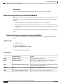
Administering Wireless Device Communication 287
Configuring Ethernet Speed and Duplex Settings 287
Configuring the Access Point for Wireless Network Management 288
Configuring the Access Point for Local Authentication and Authorization 289
Configuring the Authentication Cache and Profile 290
Example Configuration: Authentication Cache and Profile 291
Cisco 800 Series Integrated Services Routers Software Configuration Guide
OL-31704-02
xv
Contents
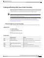
Configuring the Access Point to Provide DHCP Service 293
Setting up the DHCP Server 293
Monitoring and Maintaining the DHCP Server Access Point 295
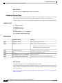
Configuring the Access Point for Secure Shell 296
Understanding SSH 296
Configuring SSH 296
Client ARP Caching 297
Understanding Client ARP Caching 297
Configuring Client ARP Caching 297
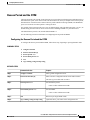
Configuring Multiple VLAN and Rate Limiting for Point-to-Multipoint Bridging 298
CHAPTER 11
Configuring PPP over Ethernet with NAT 299
Overview 300
PPPoE 300
NAT 301
Configuration Tasks 301
Configure the Virtual Private Dialup Network Group Number 301
Configure Ethernet WAN Interfaces 302
Configure the Dialer Interface 303
Configure Network Address Translation 305
Configuration Example 308
Verifying Your Configuration 309
CHAPTER 12
Configuring PPP over ATM with NAT 311
Overview 311
Configure the Dialer Interface 313
Configure the ATM WAN Interface 315
Configure DSL Signaling Protocol 316
Configuring ADSL 316
Verifying the Configuration 317
Configure Network Address Translation 318
Configuration Example 321
Verifying Your Configuration with NAT 322
CHAPTER 13
Environmental and Power Management 323
Cisco 800 Series Integrated Services Routers Software Configuration Guide
xvi
OL-31704-02
Contents
Environmental and Power Management 323
Cisco EnergyWise Support 324
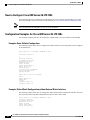
CHAPTER 14
4G LTE Wireless WAN 325
4G LTE Support on Cisco 800 Series ISRs 325
How to Configure Cisco 800 Series 4G LTE ISRs 326
Configuration Examples for Cisco 800 Series 4G LTE ISRs 326
Example: Basic Cellular Configuration 326
Example: Dialer-Watch Configuration without External Dialer Interface 326
Example: Dialer-Persistent Configuration with External Dialer Interface 327
Example: GRE Tunnel over Cellular Interface Configuration 327
Modem Firmware Upgrade 328
Troubleshooting 328
3G Support on Cisco 880G series ISRs 328
CHAPTER 15
Configuring a LAN with DHCP and VLANs 329
Configuring a LAN with DHCP and VLANs 329
DHCP 330
VLANs 330
Configuring DHCP and VLANs 330
Configuring DHCP 330
Configuration Example: DHCP 332
Verifying Your DHCP Configuration 332
Configuring VLANs 333
Assigning a Switch Port to a VLAN 334
Verifying Your VLAN Configuration 334
CHAPTER 16
Configuring a VPN Using Easy VPN and an IPSec Tunnel 337
Configuring a VPN Using Easy VPN and an IPSec Tunnel 337
Configuring the IKE Policy 339
Configuring Group Policy Information 341
Applying Mode Configuration to the Crypto Map 342
Enabling Policy Lookup 343
Configuring IPSec Transforms and Protocols 344
Configuring the IPSec Crypto Method and Parameters 345
Cisco 800 Series Integrated Services Routers Software Configuration Guide
OL-31704-02
xvii
Contents
Applying the Crypto Map to the Physical Interface 346
Creating an Easy VPN Remote Configuration 347
Verifying Your Easy VPN Configuration 349
Configuration Examples for VPN and IPSec 349
CHAPTER 17
Configuring Cisco Multimode G.SHDSL EFM/ATM 351
CHAPTER 18
Configuring VDSL2 Bonding and Single-Wire Pair 353
Restrictions 353
Configuring Bonding in Auto Mode 354
Configuring Bonding in VDSL2 Mode 354
Configuring a Single-Wire Pair on Line 0 355
Configuring a Single-Wire Pair on Line 1 356
Configuration Examples 357
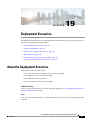
CHAPTER 19
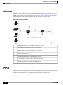
Deployment Scenarios 359
About the Deployment Scenarios 359
Enterprise Small Branch 360
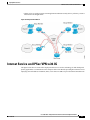
Internet Service and IPSec VPN with 3G 361
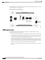
SMB Applications 362
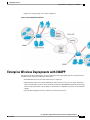
Enterprise Wireless Deployments with LWAPP 363
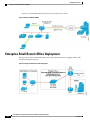
Enterprise Small Branch Office Deployment 364
CHAPTER 20
Troubleshooting Cisco 800 Series Routers 365
Getting Started 365
Before Contacting Cisco or Your Reseller 365
ADSL Troubleshooting 366
SHDSL Troubleshooting 366
VDSL2 Troubleshooting 367
show interfaces Troubleshooting Command 367
ATM Troubleshooting Commands 369
ping atm interface Command 370
show atm interface Command 370
debug atm Commands 371
Guidelines for Using Debug Commands 371
Cisco 800 Series Integrated Services Routers Software Configuration Guide
xviii
OL-31704-02
Contents
debug atm errors Command 371
debug atm events Command 372
debug atm packet Command 373
Software Upgrade Methods 374
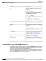
Recovering a Lost Password 374
Change the Configuration Register 374
Reset the Router 376
Reset the Password and Save Your Changes 377
Reset the Configuration Register Value 378
Cisco Configuration Professional Express 379
APPENDIX A
Cisco IOS Software Basic Skills 381
Configuring the Router from a PC 381
Understanding Command Modes 382
Getting Help 384
Enable Secret Passwords and Enable Passwords 385
Entering Global Configuration Mode 386
Using Commands 386
Abbreviating Commands 387
Undoing Commands 387
Command-Line Error Messages 387
Saving Configuration Changes 388
Summary 388
APPENDIX B
Concepts 389
ADSL 389
SHDSL 390
Network Protocols 390
IP 390
Routing Protocol Options 390
RIP 391
Enhanced IGRP 391
PPP Authentication Protocols 391
PAP 392
CHAP 392
Cisco 800 Series Integrated Services Routers Software Configuration Guide
OL-31704-02
xix
Contents
TACACS+ 393
Network Address Translation 393
Easy IP (Phase 1) 393
Easy IP (Phase 2) 394
Network Interfaces 394
Ethernet 394
ATM for DSL 395
PVC 395
Dialer Interface 395
Dial Backup 396
Backup Interface 396
Floating Static Routes 396
Dialer Watch 396
QoS 396
IP Precedence 397
PPP Fragmentation and Interleaving 397
CBWFQ 397
RSVP 398
Low Latency Queuing 398
Access Lists 398
APPENDIX C
ROM Monitor 399
Entering the ROM Monitor 399
ROM Monitor Commands 400
ROM Monitor Commands for 860VAE ISRs 401
ROM Monitor Command Descriptions 401
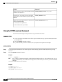
Disaster Recovery with TFTP Download 402
TFTP Download Command Variables 403
Required Variables 403
Optional Variables 403
Using the TFTP Download Command 404
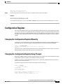
Configuration Register 405
Changing the Configuration Register Manually 405
Changing the Configuration Register Using Prompts 405
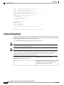
Console Download 406
Cisco 800 Series Integrated Services Routers Software Configuration Guide
xx
OL-31704-02
Contents
Error Reporting 407
ROM Monitor Debug Commands 407
Exiting the ROM Monitor 409
Cisco 800 Series Integrated Services Routers Software Configuration Guide
OL-31704-02
xxi
Contents
Cisco 800 Series Integrated Services Routers Software Configuration Guide
xxii
OL-31704-02
Preface
This preface describes the audience, organization, and conventions of this guide, and describes related
documents that have additional information. It contains the following sections:
• Audience, page xxiii
• Document Organization, page xxiii
• Document Conventions, page xxv
• Related Documentation, page xxvi
• Obtaining Documentation and Submitting a Service Request, page xxvii
Audience
This guide provides an overview and explains how to configure the various features for the Cisco 810, Cisco
860, Cisco 880, and Cisco 890 series Integrated Services Routers (ISRs). Some information may not apply
to your particular router model.
This guide is intended for Cisco equipment providers who are technically knowledgeable and familiar with
Cisco routers and Cisco IOS software and features.
For warranty, service, and support information, see the “Cisco One-Year Limited Hardware Warranty Terms”
section in the Readme First for the Cisco 800 Series Integrated Services Routers that was shipped with your
router.
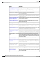
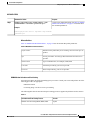
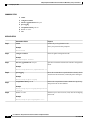
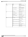
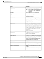
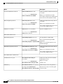
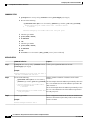
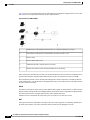
Document Organization
This document is organized into the following chapters:
Chapter
Description
Product Overview
Provides a brief description of the router models and the available software
features.
Basic Router Configuration
Provides procedures for configuring the basic parameters of the router.
Cisco 800 Series Integrated Services Routers Software Configuration Guide
OL-31704-02
xxiii
Preface
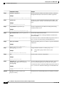
Document Organization
Chapter
Description
Configuring Ethernet CFM and Provides procedures for configuring the network interface device
Y.1731 Performance Monitoring functionality, Ethernet data plane loopback, IEEE connectivity fault
on Layer 3 Interfaces, on page management, and Y.1731 performance monitoring.
47
Configuring Power Management Provides the configuration of power management and
Power-over-Ethernet (PoE).
Configuring Security Features
Provides procedures for implementing the security features that can be
configured on the router.
Configuring Backup Data Lines
and Remote Management
Provides procedures for configuring remote management functions and
a backup data line connection.
Configuring Ethernet Switches
Provides an overview of the configuration tasks for the 4-port Fast
Ethernet switch on the router.
Configuring Voice Functionality Provides references to the procedures for voice configuration.
Configuring the Serial Interface
Provides information about WAN access and aggregation, Legacy protocol
transport, and Dial Access Server.
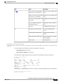
Configuring Wireless Devices
Provides procedures for initial configuration of the wireless device, radio
settings, WLAN, and administration of the wireless device.
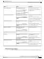
Configuring PPP over Ethernet
with NAT
Provides an overview of Point-to-Point Protocol over Ethernet (PPPoE)
clients and network address translation (NAT)s that can be configured
on the Cisco 860 and Cisco 880 series Integrated Services Routers (ISRs).
Configuring PPP over ATM with Provides an overview of Point-to-Point Protocol over Asynchronous
NAT
Transfer Mode (PPPoA) clients and network address translation (NAT)
that can be configured on the Cisco 860 and Cisco 880 series Integrated
Services Routers (ISRs).
4G LTE Wireless WAN
Provides information about 4G LTE and 3G cellular networks.
Configuring a LAN with DHCP Describes how the routers can use the Dynamic Host Configuration
and VLANs
Protocol (DHCP) to enable automatic assignment of IP configurations
for nodes on these networks.
Configuring a VPN Using Easy
VPN and an IPSec Tunnel
Provides an overview of the creation of Virtual Private Networks (VPNs)
that can be configured on the Cisco 860 and Cisco 880 series Integrated
Services Routers (ISRs).
Configuring Cisco Multimode
G.SHDSL EFM/ATM
Describes the configuration of the Cisco Multimode 4-pair G.SHDSL.
Deployment Scenarios
Shows some typical deployment scenarios for the Cisco 860, Cisco 880,
and Cisco 890 series ISRs.
Cisco 800 Series Integrated Services Routers Software Configuration Guide
xxiv
OL-31704-02
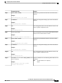
Preface
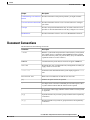
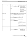
Document Conventions
Chapter
Description
Troubleshooting Cisco 800 Series Provides information to help isolate problems you might encounter.
Routers
Cisco IOS Software Basic Skills Provides information for how to use Cisco IOS software to configure
your router.
Concepts
Provides conceptual information that may be useful to Internet service
providers or network administrators when they configure Cisco routers.
ROM Monitor
Provides information on how to use Cisco’s ROM Monitor firmware.
Document Conventions
This document uses the following conventions:
Convention
Description
^ or Ctrl
Both the ^ symbol and Ctrl represent the Control (Ctrl) key on a keyboard.
For example, the key combination ^D or Ctrl-D means that you hold
down the Control key while you press the D key. (Keys are indicated in
capital letters but are not case sensitive.)
bold font
Commands and keywords and user-entered text appear in bold font.
Italic font
Document titles, new or emphasized terms, and arguments for which you
supply values are in italic font.
Courier font
Terminal sessions and information the system displays appear in courier
font.
Bold Courier font
Bold Courier font indicates text that the user must enter.
[x]
Elements in square brackets are optional.
...
An ellipsis (three consecutive nonbolded periods without spaces) after
a syntax element indicates that the element can be repeated.
|
A vertical line, called a pipe, indicates a choice within a set of keywords
or arguments.
[x | y]
Optional alternative keywords are grouped in brackets and separated by
vertical bars.
{x | y}
Required alternative keywords are grouped in braces and separated by
vertical bars.
Cisco 800 Series Integrated Services Routers Software Configuration Guide
OL-31704-02
xxv
Preface
Related Documentation
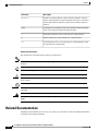
Convention
Description
[x {y | z}]
Nested set of square brackets or braces indicate optional or required
choices within optional or required elements. Braces and a vertical bar
within square brackets indicate a required choice within an optional
element.
string
A nonquoted set of characters. Do not use quotation marks around the
string or the string will include the quotation marks.
<>
Nonprinting characters such as passwords are in angle brackets.
[]
Default responses to system prompts are in square brackets.
!, #
An exclamation point (!) or a pound sign (#) at the beginning of a line
of code indicates a comment line.
Reader Alert Conventions
This document uses the following conventions for reader alerts:
Note
Tip
Caution
Timesaver
Warning
Means reader take note. Notes contain helpful suggestions or references to material not covered in the
manual.
Means the following information will help you solve a problem.
Means reader be careful. In this situation, you might do something that could result in equipment damage
or loss of data.
Means the described action saves time. You can save time by performing the action described in the
paragraph.
Means reader be warned. In this situation, you might perform an action that could result in bodily
injury.
Related Documentation
In addition to this document, the Cisco 810, Cisco 860, Cisco 880, and Cisco 890 series ISR documentation
set includes the following documents:
Cisco 800 Series Integrated Services Routers Software Configuration Guide
xxvi
OL-31704-02
Preface
Obtaining Documentation and Submitting a Service Request
• Readme First for the Cisco 800 Series Integrated Services Routers.
• Cisco 860, Cisco 880, and Cisco 890 Series Integrated Services Routers Hardware Installation Guide
• Regulatory Compliance and Safety Information for Cisco 800 Series and SOHO Series Routers
• Declarations of Conformity and Regulatory Information for Cisco Access Products with 802.11n Radios
• Software Activation on Cisco Integrated Services Routers and Cisco Integrated Service Routers G2
You might also need to refer to the following documents:
• Cisco System Manager Quick Start Guide
• Cisco IOS Release 12.4 Quality of Service Solutions Configuration Guide
• Cisco IOS Security Configuration Guide, Release 12.4
• Cisco IOS Security Configuration Guide, Release 12.4T
• Cisco IOS Security Command Reference, Release 12.4
• Cisco IOS Security Command Reference, Release 12.4T
• Cisco IOS Command Reference for Cisco Aironet Access Points and Bridges, versions 12.4(10b) JA
and 12.3(8) JEC
• Cisco Aironet 1240AG Access Point Support Documentation
• Cisco 4400 Series Wireless LAN Controllers Support Documentation
• LWAPP Wireless LAN Controllers
• LWAPP Wireless LAN Access Points
• Cisco IOS Release 12.4 Voice Port Configuration Guide
• SCCP Controlled Analog (FXS) Ports with Supplementary Features in Cisco IOS Gateways
• Cisco Software Activation Conceptual Overview
• Cisco Software Activation Tasks and Commands
Obtaining Documentation and Submitting a Service Request
For information on obtaining documentation, submitting a service request, and gathering additional information,
see the monthly What’s New in Cisco Product Documentation, which also lists all new and revised Cisco
technical documentation, at:
http://www.cisco.com/en/US/docs/general/whatsnew/whatsnew.html
Subscribe to the What’s New in Cisco Product Documentation as a Really Simple Syndication (RSS) feed
and set content to be delivered directly to your desktop using a reader application. The RSS feeds are a free
service and Cisco currently supports RSS version 2.0.
Cisco 800 Series Integrated Services Routers Software Configuration Guide
OL-31704-02
xxvii
Preface
Obtaining Documentation and Submitting a Service Request
Cisco 800 Series Integrated Services Routers Software Configuration Guide
xxviii
OL-31704-02
CHAPTER
1
Product Overview
This chapter provides an overview of the features available for the Cisco 810, Cisco 860, Cisco 880 and
Cisco 890 series Integrated Services Routers (ISRs), and contains the following sections:
• Information About Cisco 800 Series ISRs, page 1
• Cisco 860 Series ISRs, page 1
• Cisco 880 Series ISRs, page 5
• Cisco 890 Series ISRs, page 8
• Cisco 810 Series ISRs, page 10
• Licensing for Cisco 800 Series ISRs, page 14
Information About Cisco 800 Series ISRs
The Cisco 860, Cisco 880, and Cisco 890 series ISRs provide Internet, VPN, voice, data, and backup capability
to corporate teleworkers and remote and small offices of fewer than 20 users. These routers are capable of
bridging and multiprotocol routing between LAN and WAN ports, and provide advanced features such as
antivirus protection. In addition, the Cisco 860W, Cisco 880W, and Cisco 890W series ISRs incorporate an
802.11n wireless LAN option that allows the ISR to act as a wireless access point.
The Cisco 810 series ISRs provide Internet, VPN, data, and backup capability to corporate teleworkers and
remote and small offices of fewer than 20 users and provides machine to machine connectivity. Under Cisco
810 series ISRs, there are two different series of routers available - Cisco 812 series ISRs and Cisco 819 series
ISRs. The Cisco 812 ISRs support Gigabit Ethernet (GE), WAN connections over Cellular (3G) interface,
and WLAN. The Cisco 819 ISRs are fixed-configuration data routers that provide four 10/100 Fast Ethernet
(FE), 1 Gigabit Ethernet (GE), WAN connections over Serial and Cellular (3G, 4G) interfaces and WLAN.
Cisco 860 Series ISRs
The Cisco 860 series ISRs are fixed-configuration data routers that provide either a 10/100 Fast Ethernet (FE)
or an ADSL2 over POTs WAN connection.
This section contains the following topics:
Cisco 800 Series Integrated Services Routers Software Configuration Guide
OL-31704-02
1
Product Overview
Features of Cisco 860 Series ISRs
Features of Cisco 860 Series ISRs
The following features are supported on all Cisco 860 series ISRs:
4-port 10/100 FE LAN Switch of Cisco 860 Series ISRs
The 4-port 10/100 FE LAN switch provides four ports for connecting to 10/100BASE-T (10/100 Mbps) Fast
Ethernet (FE) LANs or access points.
Security Features for Cisco 860 Series ISRs
The Cisco 860 Series ISRs provide the following security features:
• IPsec
• Firewall
802.11n Wireless LAN Option for Cisco 860 Series ISRs
The Cisco 861W ISR has an integrated 802.11b/g/n single radio module for wireless LAN connectivity. With
this module, the router can then act as an access point in the local infrastructure.
Features of Cisco 860VAE Series ISRs
The following sections describe the features of the Cisco 860VAE series ISRs:
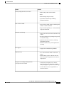
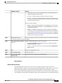
General Features of Cisco 860 VAE Series Routers
Table 1: General Features of Cisco 860VAE Series ISRs, on page 2 describes the general features of Cisco
860VAE series routers.
Table 1: General Features of Cisco 860VAE Series ISRs
Feature
Increased performance
Benefit
• Performance enables customers to take
advantage of broadband network speeds while
running secure, concurrent data, voice, video,
and wireless services.
Cisco 800 Series Integrated Services Routers Software Configuration Guide
2
OL-31704-02
Product Overview
Features of Cisco 860VAE Series ISRs
Feature
Benefit
Security and QoS with secure routers
• IPSec & Easy VPN with 10 tunnels.
• BGP.
• MAC filtering and port security.
• QoS features include LLQ and WFQ.
• NBAR and DiffServ.
State-of-the-art xDSL
• State-of-the-art xDSL features, including latest
ADSL2+/VDSL2 standards.
• Improved interoperability vs. various DSLAMs
deployed at WW SPs.
ScanSafe web filtering
• Protects network and staff from undesirable web
content
• Increases productivity by limiting time spent on
recreational surfing
• Optimizes network resources by reducing
bandwidth congestion
• Monitors online activity with comprehensive
reporting
IPv6 support
• Supports latest IP addressing standards
WAN Diversity
• GE + DSL multimode VDSL2 and ADSL 1, 2,
and 2+.
• Multiple WAN options within the same box
allow consistent configuration across diverse
deployments.
Four-port 10/100-Mbps managed switch
1 GE port for secure routers
• Connection of multiple devices within a
teleworker home or a small office, with the
ability to designate a port as the network edge.
• VLANs allow for secure segmentation of
network resources.
Cisco 800 Series Integrated Services Routers Software Configuration Guide
OL-31704-02
3
Product Overview
Features of Cisco 860VAE Series ISRs
Feature
Benefit
CON/AUX port
• A single dual-purpose port provides direct
connection to a console or external modem for
management or backup access points.
Real-time clock
• A built-in real-time clock maintains an accurate
date and time for applications that require an
accurate time stamp, such as logging and digital
certificates.
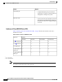
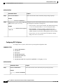
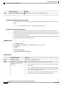
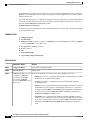
Interfaces of Cisco 860 VAE Series ISRs
Table 2: Interfaces of the Cisco 860VAE Series ISRs, on page 4 describes the interfaces of the Cisco
860VAE series routers.
Table 2: Interfaces of the Cisco 860VAE Series ISRs
Interfaces
Models
866VAE
867VAE
866VAE-K9
867VAE-K9
4 FE1 switch ports
x
x
x
x
1 GE2 switch port
—
—
x
x
1 GE WAN port
x
x
x
x
1 VDSL/ADSL over —
POTS port
x
—
x
1 VDSL/ADSL over x
ISDN port
—
x
—
1 FE = Fast Ethernet
2 GE = Gigabit Ethernet
Note
The Cisco 866VAE, 867VAE, 866VAE-K9, and 867VAE-K9 routers each have two WAN ports. Only
one of the two ports can be active at any given time.
Cisco 800 Series Integrated Services Routers Software Configuration Guide
4
OL-31704-02
Product Overview
Cisco 880 Series ISRs
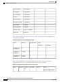
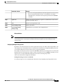
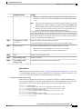
IOS Images for Cisco 860 VAE Series ISRs
Table 3: IOS Images of the Cisco 860VAE Series ISRs, on page 5 describes the IOS images included in
Cisco 860VAE series routers.
Table 3: IOS Images of the Cisco 860VAE Series ISRs
IOS Image
Model
866VAE
867VAE
867VAE-K9
x
x
—
c860vae-advsecurityk9-mz —
—
x
c860vae-advsecurityk9_npe-mz —
—
x
c860vae-ipbasek9-mz
Cisco 880 Series ISRs
The Cisco 880 series ISRs are a family of fixed-configuration data and voice routers as described in the
following sections:
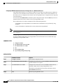
Models of Cisco 880 Series ISRs
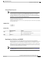
The Cisco 880 series ISRs have data and voice capabilities. Each router has one WAN port. In addition, routers
supporting voice have either FXS (Foreign Exchange Station) or BRI voice ports. Data or voice backup ports
are also available on most of the routers. The Cisco 880G routers come with a commercial third-generation
(3G) wireless interface card that provides cellular backup. 802.11b/g/n option is available on all models.
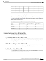
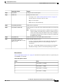
Table 4: Port Configurations of the Cisco 880 Series Data ISRs , on page 5 gives the port configurations
of Cisco 880 series data ISRs.
Table 4: Port Configurations of the Cisco 880 Series Data ISRs
Model
WAN Port
Backup
Data ISDN
Data 3G
881 and 881W
FE
—
—
881-V
FE
—
—
881G and 881GW
FE
—
x
886 and 886W
ADSL2oPOTS
x
—
Cisco 800 Series Integrated Services Routers Software Configuration Guide
OL-31704-02
5
Product Overview
Models of Cisco 880 Series ISRs
886G and 886GW
ADSL2oPOTS
—
x
887 and 887W
ADSL2oPOTS
x
—
887G and 887GW
ADSL2oPOTS
—
x
887-VA-V
VDSL2oPOTS
x
x
887V and 887VW
VDSL2oPOTS
x
—
887VG and 887VGW
VDSL2oPOTS
—
x
888 and 888W
G.SHDSL
x
—
888G and 888GW
G.SHDSL
—
x
888E and 888EW
EFM over G.SHDSL
x
—
C888EA-K9
Multimode
x
—
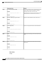
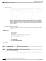
Table 5: Port Configurations of Cisco 880 Series Voice ISRs , on page 6 gives the port configurations of
Cisco 880 series voice ISRs.
Table 5: Port Configurations of Cisco 880 Series Voice ISRs
Model
WAN Port
FXS Voice Ports
Backup
PSTN FXO
PSTN BRI
C881SRST and
C881SRSTW
FE
4
x
—
C888SRST and
C888SRSTW
G.SHDSL
4
—
x
C888ESRST and
C888ERSTW
EFM over
G.SHDSL
4
—
4
Table 6: Port Configurations of Cisco 880 Series Data and Voice ISRs , on page 6 gives the port
configurations of Cisco 881-V, Cisco887VA-V, and Cisco 887VA-V-W series ISRs.
Table 6: Port Configurations of Cisco 880 Series Data and Voice ISRs
Model
WAN Port
FXS Voice
Ports
PSTN BRI
WLAN
Backup
PSTN FXO Data (ISDN)
Cisco 800 Series Integrated Services Routers Software Configuration Guide
6
OL-31704-02
Product Overview
Common Features of Cisco 880 Series ISRs
C881-V
FE
4
2
—
1
—
C887VA-V
VDSL2/ADSL2 4
2
—
—
x
C887VA-V-W VDSL2/ADSL2 4
2
x
—
x
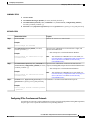
The Cisco 887 VA-V and Cisco 881-V routers give you the flexibility to use the FXS or BRI voice ports (The
Cisco 881-V router also supports a backup FX0 port), but the number of concurrent calls that the router
supports is limited by the codec complexity configuration. The router supports less calls when the codec
complexity setting is configured for high complexity. Table 7: Number of Concurrent Calls Supported on
Cisco 880 Series Data and Voice ISRs, on page 7 shows the number of concurrent calls that is supported
on the router for each codec complexity setting. Configuring the codec complexity setting to support secure
calls does not affect the numbers below.
Table 7: Number of Concurrent Calls Supported on Cisco 880 Series Data and Voice ISRs
Model
Flexible Complexity
Medium Complexity
High Complexity
C881-V
9
8
6
C887VA-V
8
8
6
C887VA-V-W
8
8
6
Common Features of Cisco 880 Series ISRs
Cisco 880 series ISRs support the following features:
4-port 10/100 FE LAN Switch of Cisco 880 Series ISRs
This switch provides four ports for connecting to 10/100BASE-T FE LANs, access points, or IP phones. In
addition, an upgrade is available that gives Power over Ethernet (PoE) on two of the ports to provide power
to access points or phones.
802.11n Wireless LAN Option of Cisco 880 Series ISRs
The Cisco 880W series ISRs have an integrated 802.11b/g/n single radio module for wireless LAN connectivity.
With this module, the router can act as an access point in the local infrastructure.
Real-Time Clock of Cisco 880 Series ISRs
A real-time clock (RTC) provides date and time when the system is powered on. The RTC is used to verify
the validity of the Certification Authority stored on the router.
Cisco 800 Series Integrated Services Routers Software Configuration Guide
OL-31704-02
7
Product Overview
Voice Features of Cisco 880 Series ISRs
Security Features of Cisco 880 Series ISRs
The Cisco 880 Series ISRs provide the following security features:
• Intrusion Prevention System (IPS)
• Dynamic Multipoint VPN (DMVPN)
• IPsec
• Quality of service (QoS)
• Firewall
• URL filtering
Voice Features of Cisco 880 Series ISRs
The Cisco 880 voice and data platforms (C880SRST, C880SRSTW, C881-V, C887 VA-V, and C887VA-V-W)
support the following voice features:
• Signaling protocols: Session Initiation Protocol (SIP), Media Gateway Control Protocol (MGCP), and
H323
• Real-time transfer protocol (RTP), Cisco RTP (cRTP), and secure RTP (SRTP) for these signaling
protocols
• Fax passthrough, Cisco fax relay, T37 fax store-and-forward, and T.38 fax relay (including T.38
gateway-controlled MGCP fax relay)
• Dual tone multifrequency (DTMF) Relay—OOB and RFC2833
• Silence suppression/comfort noise
• G.711 (a-law and u-law), G.729A, G.729AB, G.729, G.729B, G.726
• Support of SRST failover to a Foreign Exchange Office (FXO) or BRI backup port connected to PSTN
in case of WAN failure on C880SRST and C880SRSTW.
• Support for SRST and CME requires user license, but only a 5-user license is supported on C881-V,
C887VA-V, and C887VA-V-W routers.
• Direct inward dialing (DID) on FXS
Cisco 890 Series ISRs
The Cisco 890 series ISRs are fixed-configuration data routers. These routers have a Gigabit Ethernet WAN
port and data backup ports.
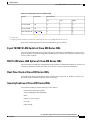
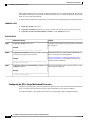
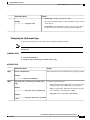
Table 8: Port Configurations of the Cisco 890 Series ISRs, on page 9 gives the port configurations for the
Cisco 890 Series ISRs.
Cisco 800 Series Integrated Services Routers Software Configuration Guide
8
OL-31704-02
Product Overview
8-port 10/100 FE LAN Switch of Cisco 890 Series ISRs
Table 8: Port Configurations of the Cisco 890 Series ISRs
Model
WAN Port
Data Backup
FE
V.92
ISDN
891 and 891W
GE
x
x
—
892 and 892W
GE
x
—
x
892F and 892F-W
GE3 or SFP4
x
—
x
3 GE copper port.
4 SFP port supports GE with fiber. For a complete list of SFPs supported, see the Cisco 892F ISR data sheet on Cisco.com.
Some of the features supported on Cisco 890 series ISRs are given as follows:
8-port 10/100 FE LAN Switch of Cisco 890 Series ISRs
The 8-port 10/100 FE LAN switch provides eight ports for connecting to 10/100BASE-T FE LANs, access
points, or IP phones. In addition, an upgrade is available that gives PoE on four of the ports to provide power
to access points or phones.
802.11n Wireless LAN Option of Cisco 890 Series ISRs
The Cisco 890W series ISRs have integrated 802.11b/g/n and 802.11a/n dual radio modules for wireless LAN
connectivity. With these modules, the router can act as an access point in the local infrastructure.
Real-Time Clock of Cisco 890 Series ISRs
A real-time clock (RTC) provides date and time when the system is powered on. The RTC is used to verify
the validity of the Certification Authority stored on the router.
Security Features of Cisco 890 Series ISRs
Cisco 890 Series ISRs provide the following security features:
• Intrusion Prevention System (IPS)
• Dynamic Multipoint VPN (DMVPN)
• IPsec
• Quality of service (QoS)
• Firewall
• URL filtering
Cisco 800 Series Integrated Services Routers Software Configuration Guide
OL-31704-02
9
Product Overview
Cisco 810 Series ISRs
Cisco 810 Series ISRs
This section provides information about the features supported by Cisco 810 series ISRs. In Cisco 810 series
ISRs, there are two different series of routers available - Cisco 812 series ISRs and Cisco 819 series ISRs.
This section contains the following topics:
Features of Cisco 812 Series ISRs
This section lists the software, platform, and security features supported by the Cisco 812 Series ISRs.
Note
The WAAS Express feature is not supported. This feature will be supported for 3G and 4G interfaces with
later IOS releases.
3G Features of Cisco 812 Series ISR
The 3rd Generation (3G) is a generation of standards for mobile technology that facilitates growth, increased
in bandwidth, and supports more diverse applications. The following 3G features are supported in Cisco 812
series ISR.
• Modem control and management
• Asynchronous transport (AT) command set
• Wireless Host Interface Protocol (WHIP)
• Control and Status (CNS) for out-of-band modem control and status
• Diagnostic Monitor (DM) logging
• Account provisioning
• Modem firmware upgrade
• SIM locking and unlocking
• MEP unlocking
• OMA-DM activation, voice-initiated data callback
• Dual SIM card slots
• Link persistence
• SMS Services
• Global Positioning System (GPS) Services
• 3G MIB
Cisco 800 Series Integrated Services Routers Software Configuration Guide
10
OL-31704-02
Product Overview
Features of Cisco 812 Series ISRs
WLAN Features of Cisco 812 Series ISR
A Wireless Local Area Network (WLAN) implements a flexible data communication system frequently
augmenting rather than replacing a wired LAN within a building or campus. WLANs use radio frequency to
transmit and receive data over the air, minimizing the need for wired connections.
Cisco 812 ISR supports the following WLAN features:
Dual Radio of Cisco 812 Series ISR
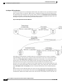
The Cisco 802 Access Points (AP802) is an integrated access point on Cisco 812 ISRs. The access point is a
wireless LAN transceiver that acts as the connection point between wireless and wired networks or as the
center point of a standalone wireless network. In large installations, the roaming functionality provided by
multiple access points enables wireless users to move freely throughout the facility while maintaining
uninterrupted access to the network.
AP802 Dual Radio contains two different types of wirelesss radio that can support connections on both 2.4
Ghz used by 802.11b, 802.11g, and 802.11n and 5 Ghz used by 802.11a and 802.11n.
All the WLAN traffic for Cisco 812 ISR passes through the Ethernet WAN or 3G interface. The AP802 Dual
Radio is supported on the following SKUs:
• C812G-CIFI+7-E-K9
• C812G-CIFI+7-N-K9
• C812G-CIFI-V-A-K9
• C812G-CIFI-S-A-K9
Cleanair Technology of Cisco 812 Series ISR
The CleanAir is a new wireless technology that intelligently avoids Radio Frequency (RF) to protect 802.11n
performance. For more information, see Cisco CleanAir Technology . This feature is supported in all SKUs
that has WLAN support.
Dynamic Frequency Selection of Cisco 812 Series ISR
The Dynamic Frequency Selection (DFS) is the process of detecting radar signals that must be protected
against 802.11a interference and upon detection switching the 802.11a operating frequency to one that is not
interfering with the radar systems. Transmit Power Control (TPC) is used to adapt the transmission power
based on regulatory requirements and range information.
Note
The DFS functionality is disabled for FCC SKUs pending FCC certification. For more information, see
Dynamic Frequency Selection and IEEE 802.11h Transmit Power Control .
Platform Features of Cisco 812 Series ISR
For the complete list of Cisco 812 ISR platform features, see Platform Features.
Cisco 800 Series Integrated Services Routers Software Configuration Guide
OL-31704-02
11
Product Overview
Features of Cisco 819 Series ISRs
TFTP with Ethernet WAN Interface Feature of Cisco 812 Series ISR
For more information on TFTP download, see Disaster Recovery with TFTP Download .
Note
The Cisco 812 ISR has a GE interface as the only Ethernet interface. Hence, the port number is automatically
set at Rommon for TFTP connectivity.
SKU Information for Cisco 812 Series ISR
See the following link for SKUs available for Cisco 812 series ISR router:
http://www.cisco.com/en/US/docs/routers/access/800/812/hardware/install/guide/overview.html#wp1057240
SKU information for Cisco 812 series
Features of Cisco 819 Series ISRs
This section lists the software, platform, and security features supported by the Cisco 819 Series ISRs.
Note
The WAAS Express feature is not supported. This feature will be supported for 3G and 4G interfaces with
later IOS releases.
3G Features of Cisco 819 Series ISRs
The following 3G features are supported by Cisco 819 series ISR routeres .
• Modem control and management
• Asynchronous transport (AT) command set
• Wireless Host Interface Protocol (WHIP)
• Control and Status (CNS) for out-of-band modem control and status
• Diagnostic Monitor (DM) logging
• Account provisioning
• Modem firmware upgrade
• SIM locking and unlocking
• MEP unlocking
• OMA-DM activation
• Dual SIM card slots
• Link persistence
• SMS Services
Cisco 800 Series Integrated Services Routers Software Configuration Guide
12
OL-31704-02
Product Overview
Features of Cisco 819 Series ISRs
• Global Positioning System (GPS) Services
• 3G MIB
WLAN Features of Cisco 819 Series ISRs
Cisco 819 series ISRs support the following WLAN features:
• Dual Radio
• CleanAir Technology
• Dynamic Frequency Selection
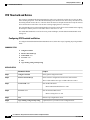
4G LTE Features of Cisco 819 Series ISRs
Cisco 819 series ISRs supports the following 4G LTE features:
• IPv4 bearer
• MIPv4, NEMOv4, RFC 3025
• IPv4 subnet behind LTE UE interface
• Evolved High-Rate Packet Data (EHRPD), which allows seamless handoff between 4G LTE and 3G
services (C819(H)G-4G-V-K9 only)
• Seamless hand-off between LTE and EHRPD network (C819(H)G-4G-V-K9 only)
• Support for UMTS service as a fallback option from LTE service (C819(H)G-4G-A-K9 and
C819(H)G-4G-G-K9 only)
• Seamless handoff between LTE and UMTS service (C819(H)G-4G-A-K9 and C819(H)G-4G-G-K9
only)
• Remote access to Qualcomm diagnostic monitor port
• OTA-DM including wireless configuration FOTA (C819(HG-4G-V-K9 only)
• Mini USB type 2 connector for modem provisioning
Platform Features of Cisco 819 Series ISRs
For the complete list of Cisco 819 Series ISRs platform features, see Platform Features for Cisco 819 ISRs .
Security Features of Cisco 819 Series ISRs
The Cisco 819 Series ISRs provide the following security features:
• Intrusion Prevention System (IPS)
• Dynamic Multipoint VPN (DMVPN)
• IPsec
• Quality of service (QoS)
Cisco 800 Series Integrated Services Routers Software Configuration Guide
OL-31704-02
13
Product Overview
Licensing for Cisco 800 Series ISRs
• Firewall
• URL filtering
SKU Information for Cisco 819 Series ISRs
See the following link for SKUs available for Cisco 819 series ISRs:
http://www.cisco.com/c/en/us/td/docs/routers/access/800/hardware/installation/guide/800HIG/
prodoverview.html#pgfId-1146483
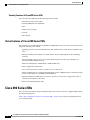
Licensing for Cisco 800 Series ISRs
The Cisco 810, 860, Cisco 880, and Cisco 890 ISRs ship with licensed software installed. Software features
may be upgraded and the software licenses may be managed through Cisco Licensing Manager . See Software
Activation On Cisco Integrated Services Routers and Cisco Integrated Service Routers G2 for details.
When you order a new router, you specify the software image and feature set that you want. The image and
feature set are installed on your router before you receive it, so you do not need to purchase a software license.
The router stores the software license file on the flash memory.
Note
The Cisco 860VAE does not require licenses.
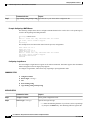
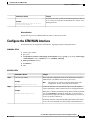
Selecting Feature Sets for Cisco 800 Series ISRs
Some feature sets are bundled and offered with a software license that is installed on the hardware platforms.
For a list of features available with a software license on the Cisco 810, Cisco 860, Cisco 880, and Cisco 890
platforms, see Cisco 812 Data Sheet Cisco 819 Data Sheet , Cisco 860 Data Sheet , Cisco 880 Data Sheet ,
and Cisco 890 Data Sheet . See Cisco IOS Software Activation Tasks and Commands for details about how
to activate and manage the software licenses.
Cisco 800 Series Integrated Services Routers Software Configuration Guide
14
OL-31704-02
CHAPTER
2
Basic Router Configuration
This chapter provides procedures for configuring the basic parameters of your Cisco router, including global
parameter settings, routing protocols, interfaces, and command-line access. It also describes the default
configuration on startup.
Note
Individual router models may not support every feature described in this guide. Features that are not
supported by a particular router are indicated whenever possible.
This chapter includes configuration examples and verification steps, as available.
For complete information on how to access global configuration mode, see the Entering Global Configuration
Mode section.
• Interface Ports, page 15
• Default Configuration, page 16
• Information Needed for Configuration, page 17
• Configuring Command-Line Access, page 19
• Configuring Global Parameters, page 21
• Configuring WAN Interfaces, page 22
• Configuring a Loopback Interface, page 39
• Configuring Static Routes, page 41
• Configuring Dynamic Routes, page 42
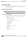
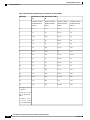
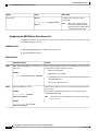
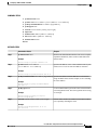
Interface Ports
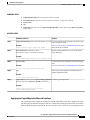
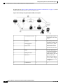
Table 9: Supported Interfaces and Associated Port Labels by Cisco Router , on page 16 lists the interfaces
that are supported for each router and their associated port labels on the equipment.
Cisco 800 Series Integrated Services Routers Software Configuration Guide
OL-31704-02
15
Basic Router Configuration
Default Configuration
Table 9: Supported Interfaces and Associated Port Labels by Cisco Router
Router
Interface
Port Label
Cisco 819 Router
4-port Fast Ethernet LAN
LAN, FE0–FE3
Gigabit Ethernet WAN
GE WAN 0
Serial
Serial
Mini USB for 3G port Provisioning 3G RSVD
Console/Aux port
Note
CON/AUX
There are two labels for the associated antennas with the labels: Main and DIV/GPS.
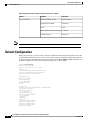
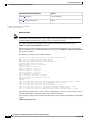
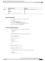
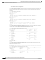
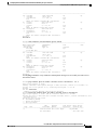
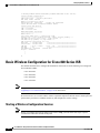
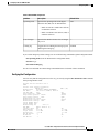
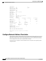
Default Configuration
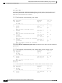
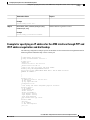
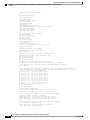
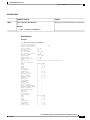
When you first boot up your Cisco router, some basic configuration has already been performed. All of the
LAN and WAN interfaces have been created, console and vty ports are configured, and the inside interface
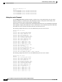
for Network Address Translation (NAT) has been assigned. Use the show running-config command to view
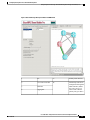
the initial configuration, as shown in the following example for a Cisco 819 ISR:
Router# show running
Building configuration...
Current configuration : 977 bytes
!
version 15.1
service timestamps debug datetime msec
service timestamps log datetime msec
no service password-encryption
!
hostname Router
!
boot-start-marker
boot-end-marker
no aaa new-model
ip source-route
ip cef
no ipv6 cef
license udi pid CISCO819G-G-K9 sn FHK1429768Q
controller Cellular 0
interface Cellular0
no ip address
encapsulation ppp
interface Ethernet-wan0
no ip address
shutdown
duplex auto
speed auto
interface FastEthernet0
interface FastEthernet1
interface FastEthernet2
interface FastEthernet3
interface Serial0
Cisco 800 Series Integrated Services Routers Software Configuration Guide
16
OL-31704-02
Basic Router Configuration
Information Needed for Configuration
no ip address
shutdown
no fair-queue
clock rate 2000000
!
interface Vlan1
no ip address
!
ip forward-protocol nd
no ip http server
no ip http secure-server
logging esm config
control-plane
line con 0
no modem enable
line aux 0
line 3
no exec
line 7
stopbits 1
speed 115200
line vty 0 4
login
transport input all
!
scheduler allocate 20000 1000
end
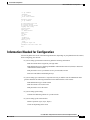
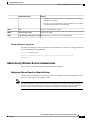
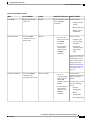
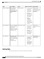
Information Needed for Configuration
You need to gather some or all of the following information, depending on your planned network scenario,
before configuring your network:
• If you are setting up an Internet connection, gather the following information:
◦PPP client name that is assigned as your login name
◦PPP authentication type: Challenge Handshake Authentication Protocol (CHAP) or Password
Authentication Protocol (PAP)
◦PPP password to access your Internet service provider (ISP) account
◦DNS server IP address and default gateways
• If you are setting up a connection to a corporate network, you and the network administrator must
generate and share the following information for the WAN interfaces of the routers:
◦PPP authentication type: CHAP or PAP
◦PPP client name to access the router
◦PPP password to access the router
• If you are setting up IP routing:
◦Generate the addressing scheme for your IP network.
• If you are setting up the serial interface:
◦Mode of operation (sync, async, bisync)
◦Clock rate depending on the mode
Cisco 800 Series Integrated Services Routers Software Configuration Guide
OL-31704-02
17
Basic Router Configuration
Information Needed for Configuration
◦IP address depending on the mode
• If you are setting up 3G:
◦You must have service availability on the Cisco 819 ISR from a carrier, and you must have network
coverage where your router will be physically placed. For a complete list of supported carriers,
see the data sheet at Cisco 3G Wireless Connectivity Solutions.
◦You must subscribe to a service plan with a wireless service provider and obtain a SIM card.
◦You must install the SIM card before configuring the 3G Cisco 819 ISR. For instructions on how
to install the SIM card, see the Cisco 800 Series Hardware Installation Guide.
• You must install the required antennas before you configure the 3G for Cisco 819 ISR. See the following
URLs for instructions on how to install the antennas:
◦3G-ANTM1919D—See Cisco Multiband Swivel-Mount Dipole Antenna (3G-ANTM1919D).
◦3G-ANTM1916-CM—See Cisco Multiband Omnidirectional Ceiling Mount Antenna
(3G-ANTM1916-CM).
◦3G-AE015-R (Antenna Extension)—See Cisco Single-Port Antenna Stand for Multiband TNC
Male-Terminated Portable Antenna (Cisco 3G-AE015-R).
◦3G-AE010-R (Antenna Extension)—See Cisco Single-Port Antenna Stand for Multiband TNC
Male-Terminated Portable Antenna (Cisco 3G-AE015-R). This document applies to both
3G-AE015-R and 3G-AE010-R. The only difference between these two products is the length of
the cable.
◦3G-ANTM-OUT-OM—See Cisco 3G Omnidirectional Outdoor Antenna (3G-ANTM-OUT-OM).
◦3G-ANTM-OUT-LP—See Cisco Multiband Omnidirectional Panel-Mount Antenna
(3G-ANTM-OUT-LP).
◦3G-ACC-OUT-LA—See Cisco 3G Lightning Arrestor (3G-ACC-OUT-LA).
◦4G-ANTM-OM-CM—See Cisco 4G Indoor Ceiling-Mount Omnidirectional Antenna
(4G-ANTM-OM-CM).
• You must check your LEDs for signal reception as described in Table 21: 3G LED Descriptions for
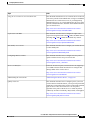
Cisco 819 Series ISRs, on page 171.
• You should be familiar with the Cisco IOS software. See the Cisco IOS documentation beginning with
Release 12.4(15)T or later for Cisco 3G support.
• To configure your 3G data profile, you will need the username, password, and access point name (APN)
from your service provider:
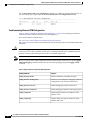
After you have collected the appropriate information, you can perform a full configuration on your router,
beginning with the tasks in the Configuring Command-Line Access, on page 19.
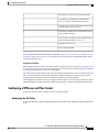
To obtain or change software licenses:
• See Software Activation on Cisco Integrated Services Routers and Cisco Integrated Service Routers G2.
Cisco 800 Series Integrated Services Routers Software Configuration Guide
18
OL-31704-02
Basic Router Configuration
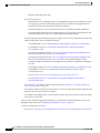
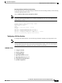
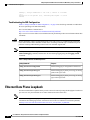
Configuring Command-Line Access
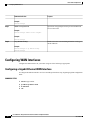
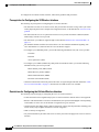
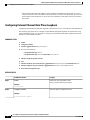
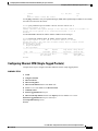
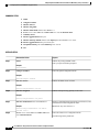
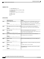
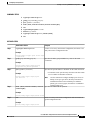
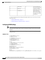
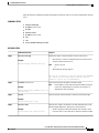
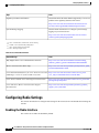
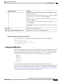
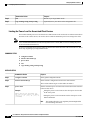
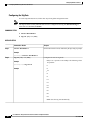
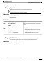
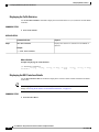
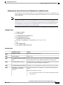
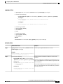
Configuring Command-Line Access
To configure parameters to control access to the router, perform the following steps, beginning in global
configuration mode:
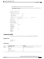
SUMMARY STEPS
1. line [aux | console | tty | vty] line-number
2. password password
3. login
4. exec-timeout minutes [seconds]
5. line [aux | console | tty | vty] line-number
6. password password
7. login
8. end
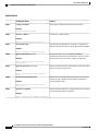
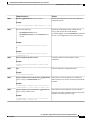
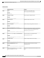
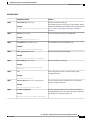
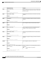
DETAILED STEPS
Step 1
Command or Action
Purpose
line [aux | console | tty | vty] line-number
Enters line configuration mode and specifies the type of
line.
Example:
This example specifies a console terminal for access.
Router(config)# line console 0
Example:
Router(config-line)#
Step 2
password password
Specifies a unique password for the console terminal line.
Example:
Router(config)# password 5dr4Hepw3
Example:
Router(config-line)#
Step 3
login
Enables password checking at terminal session login.
Example:
Router(config-line)# login
Example:
Router(config-line)#
Cisco 800 Series Integrated Services Routers Software Configuration Guide
OL-31704-02
19
Basic Router Configuration
Configuring Command-Line Access
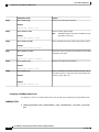
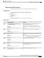
Step 4
Command or Action
Purpose
exec-timeout minutes [seconds]
Sets the interval that the EXEC command interpreter waits
until user input is detected. The default is 10 minutes.
Optionally, add seconds to the interval value.
Example:
Router(config-line)# exec-timeout 5 30
This example shows a timeout of 5 minutes and 30 seconds.
Entering a timeout of 0 0 specifies never to time out.
Example:
Router(config-line)#
Step 5
line [aux | console | tty | vty] line-number
Specifies a virtual terminal for remote console access.
Example:
Router(config-line)# line vty 0 4
Example:
Router(config-line)#
Step 6
password password
Specifies a unique password for the virtual terminal line.
Example:
Router(config-line)# password aldf2ad1
Example:
Router(config-line)#
Step 7
Enables password checking at the virtual terminal session
login.
login
Example:
Router(config-line)# login
Example:
Router(config-line)#
Step 8
Exits line configuration mode and returns to privileged
EXEC mode.
end
Example:
Router(config-line)# end
Example:
Router#
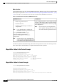
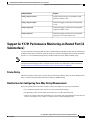
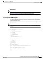
What to Do Next
Example
Cisco 800 Series Integrated Services Routers Software Configuration Guide
20
OL-31704-02
Basic Router Configuration
Configuring Global Parameters
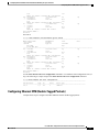
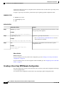
The following configuration shows the command-line access commands.
You do not need to input the commands marked “default.” These commands appear automatically in the
configuration file generated when you use the show running-config command.
!
line con 0
exec-timeout 10 0
password 4youreyesonly
login
transport input none (default)
stopbits 1 (default)
line vty 0 4
password secret
login
!
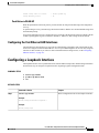
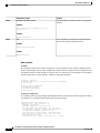
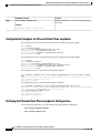
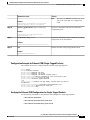
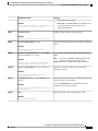
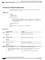
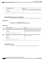
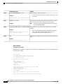
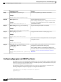
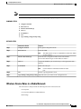
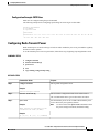
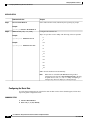
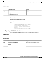
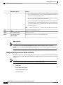
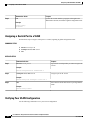
Configuring Global Parameters
To configure selected global parameters for your router, perform these steps:
SUMMARY STEPS
1. configure terminal
2. hostname name
3. enable secret password
4. no ip domain-lookup
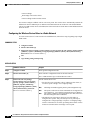
DETAILED STEPS
Step 1
Command or Action
Purpose
configure terminal
Enters global configuration mode when using the console
port.
Example:
If you are connecting to the router using a remote terminal,
use the following:
Router> enable
Example:
Router# configure terminal
telnet router name or address
Login: login id
Password: *********
Example:
Router> enable
Router(config)#
Step 2
hostname name
Specifies the name for the router.
Example:
Router(config)# hostname Router
Cisco 800 Series Integrated Services Routers Software Configuration Guide
OL-31704-02
21
Basic Router Configuration
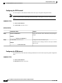
Configuring WAN Interfaces
Command or Action
Purpose
Example:
Router(config)#
Step 3
enable secret password
Specifies an encrypted password to prevent unauthorized
access to the router.
Example:
Router(config)# enable secret cr1ny5ho
Example:
Router(config)#
Step 4
no ip domain-lookup
Disables the router from translating unfamiliar words (typos)
into IP addresses.
Example:
Router(config)# no ip domain-lookup
Router(config)#
Configuring WAN Interfaces
Configure the WAN interface for your router using one of the following as appropriate:
Configuring a Gigabit Ethernet WAN Interface
To configure the Ethernet interface on a Cisco 819 ISR, perform these steps, beginning in global configuration
mode:
SUMMARY STEPS
1. interface type number
2. ip address ip-address mask
3. no shutdown
4. exit
Cisco 800 Series Integrated Services Routers Software Configuration Guide
22
OL-31704-02
Basic Router Configuration
Configuring the Cellular Wireless WAN Interface
DETAILED STEPS
Step 1
Command or Action
Purpose
interface type number
Enters the configuration mode for a Gigabit Ethernet WAN
interface on the router.
Example:
Router(config)# interface gigabitethernet 0
Example:
Router(config-if)#
Step 2
Sets the IP address and subnet mask for the specified
Gigabit Ethernet interface.
ip address ip-address mask
Example:
Router(config-if)# ip address 192.168.12.2
255.255.255.0
Example:
Router(config-if)#
Step 3
no shutdown
Enables the Ethernet interface, changing its state from
administratively down to administratively up.
Example:
Router(config-if)# no shutdown
Example:
Router(config-if)#
Step 4
Exits configuration mode for the Gigabit Ethernet interface
and returns to global configuration mode.
exit
Example:
Router(config-if)# exit
Example:
Router(config)#
Configuring the Cellular Wireless WAN Interface
The Cisco 819 ISRs provide a Third-Generation (3G) wireless interface for use over Global System for Mobile
Communications (GSM) and code division multiple access (CDMA) networks. The interface is a 34-millimetre
embedded mini express card.
Its primary application is WAN connectivity as a backup data link for critical data applications. However, the
3G wireless interface can also function as the router’s primary WAN connection.
Cisco 800 Series Integrated Services Routers Software Configuration Guide
OL-31704-02
23
Basic Router Configuration
Configuring the Cellular Wireless WAN Interface
To configure the 3G cellular wireless interface, follow these guidelines and procedures:
Prerequisites for Configuring the 3G Wireless Interface
The following are prerequisites to configuring the 3G wireless interface:
• You must have wireless service from a carrier, and you must have network coverage where your router
will be physically placed. For a complete list of supported carriers, see the data sheet at: www.cisco.com/
go/m2m
• You must subscribe to a service plan with a wireless service provider and obtain a SIM card (GSM
modem only) from the service provider.
• You must check your LEDs for signal strength, as described in LEDs for Cisco 819 Series ISRs, on
page 171.
• You should be familiar with the Cisco IOS software. See Cisco IOS documentation beginning with
Cisco IOS Release 12.4(15)XZ or later for Cisco 3G Wireless support.
• To configure your GSM data profile, you need the following information from your service provider:
◦Username
◦Password
◦Access point name (APN)
• To configure your CDMA (CDMA only) data profile for manual activation, you need the following
information from your service provider:
◦Master Subsidy Lock (MSL) number
◦Mobile Directory number (MDN)
◦Mobile Station Identifier (MSID)
◦Electronic Serial Number (ESN)
• Check the LED located on the front panel of the router for signal strength and other indications. LEDs
for Cisco 819 Series ISRs, on page 171 describes the 3G LEDs for the Cisco 819 ISR.
Restrictions for Configuring the Cellular Wireless Interface
The following restrictions apply to configuring the Cisco 3G wireless interface:
• A data connection can be originated only by the 3G wireless interface. Remote dial-in is not supported.
• Because of the shared nature of wireless communications, the experienced throughput varies depending
on the number of active users or the amount of congestion in a given network.
• Cellular networks have higher latency than wired networks. Latency rates depend on the technology and
carrier. Latency may be higher when there is network congestion.
• VoIP is currently not supported.
• Any restrictions that are part of the terms of service from your carrier also apply to the Cisco 3G wireless
interface.
Cisco 800 Series Integrated Services Routers Software Configuration Guide
24
OL-31704-02
Basic Router Configuration
Configuring the Cellular Wireless WAN Interface
• Inserting a different type of modem from what was previously removed requires configuration changes
and you must reload the system.
Data Account Provisioning
Note
To provision your modem, you must have an active wireless account with a service provider. A SIM card
must be installed in a GSM 3G wireless card.
To provision your data account, follow these procedures:
Verifying Signal Strength and Service Availability
To verify the signal strength and service availability on your modem, use the following commands in privileged
EXEC mode.
SUMMARY STEPS
1. show cellular 0 network
2. show cellular 0 hardware
3. show cellular 0 connection
4. show cellular 0 gps
5. show cellular 0 radio
6. show cellular 0 profile
7. show cellular 0 security
8. show cellular 0 sms
9. show cellular 0 all
DETAILED STEPS
Step 1
Command or Action
Purpose
show cellular 0 network
Displays information about the carrier network, cell site, and
available service.
Example:
Router# show cellular 0 network
Step 2
Displays the cellular modem hardware information.
show cellular 0 hardware
Example:
Router# show cellular 0 hardware
Step 3
Displays the current active connection state and data
statistics.
show cellular 0 connection
Example:
Router# show cellular 0 connection
Cisco 800 Series Integrated Services Routers Software Configuration Guide
OL-31704-02
25
Basic Router Configuration
Configuring the Cellular Wireless WAN Interface
Step 4
Command or Action
Purpose
show cellular 0 gps
Displays the cellular gps information.
Example:
Router# show cellular 0 gps
Step 5
show cellular 0 radio
Shows the radio signal strength.
Note
Example:
The RSSI should be better than –90 dBm for steady
and reliable connection.
Router# show cellular 0 radio
Step 6
show cellular 0 profile
Shows information about the modem data profiles created.
Example:
Router# show cellular 0 profile
Step 7
show cellular 0 security
Shows the security information for the modem, such as SIM
and modem lock status.
Example:
Router# show cellular 0 security
Step 8
show cellular 0 sms
Displays the cellular sms information.
Example:
Router# show cellular 0 sms
Step 9
show cellular 0 all
Example:
Shows consolidated information about the modem, such as
the profiles that were created, the radio signal strength, the
network security, and so on.
Example:
Router# show cellular 0 all
Configuring a GSM Modem Data Profile
To configure or create a new modem data profile, enter the following command in privileged EXEC mode.
SUMMARY STEPS
1. cellular 0 gsm profile create <profile number> <apn> <authentication> <username> <password>
ipv4
Cisco 800 Series Integrated Services Routers Software Configuration Guide
26
OL-31704-02
Basic Router Configuration
Configuring the Cellular Wireless WAN Interface
DETAILED STEPS
Step 1
Command or Action
Purpose
cellular 0 gsm profile create <profile number> <apn>
<authentication> <username> <password> ipv4
Creates a new modem data profile. See Table 10: Modem
Data Profile Parameters, on page 27 for details about
the command parameters.
Example:
Router# gsm profile create 2 <apn-name> chap username
password ipv4
What to Do Next
Table 10: Modem Data Profile Parameters, on page 27 lists the modem data profile parameters.
Table 10: Modem Data Profile Parameters
profile number
Number for the profile that you are creating. You can create up to 16
profiles.
apn
Access point name. You must get this information from the service
provider.
authentication
Type of authentication, for example, CHAP, PAP.
Username
Username provided by your service provider.
Password
Password provided by your service provider.
CDMA Modem Activation and Provisioning
Activation procedures may differ, depending upon your carrier. Consult your carrier and perform one of the
following procedures as appropriate:
• Manual activation
• Activating using over-the-air service provisioning
The following table lists the activation and provisioning processes supported by different wireless carriers.
Table 11:
Activation and Provisioning Process
Carrier
Manual Activation using MDN, MSID, MSL
Sprint
Cisco 800 Series Integrated Services Routers Software Configuration Guide
OL-31704-02
27
Basic Router Configuration
Configuring the Cellular Wireless WAN Interface
Activation and Provisioning Process
Carrier
OTASP5 Activation
Verizon Wireless
IOTA6 for Data Profile refresh
Sprint
5 OTASP = Over the Air Service Provisioning.
6 IOTA = Internet Over the Air.
Manual Activation
Note
You must have valid mobile directory number (MDN), mobile subsidy lock (MSL), and mobile station
identifier (MSID) information from your carrier before you start this procedure.
To configure a modem profile manually, use the following command, beginning in EXEC mode:
cellular unit cdma activate manual mdn msid msl
Besides being activated, the modem data profile is provisioned through the Internet Over the Air (IOTA)
process. The IOTA process is initiated automatically when you use the cellular unit cdma activate manual
mdn msid msl command.
The following is a sample output from this command:
router# cellular 0 cdma activate manual 1234567890 1234567890 12345
NAM 0 will be configured and will become Active
Modem will be activated with following Parameters
MDN :1234567890; MSID :1234567890; SID :1234; NID 12:
Checking Current Activation Status
Modem activation status: Not Activated
Begin Activation
Account activation - Step 1 of 5
Account activation - Step 2 of 5
Account activation - Step 3 of 5
Account activation - Step 4 of 5
Account activation - Step 5 of 5
Secure Commit Result: Succeed
Done Configuring - Resetting the modem
The activation of the account is Complete
Waiting for modem to be ready to start IOTA
Beginning IOTA
router#
*Feb 6 23:29:08.459: IOTA Status Message Received. Event: IOTA Start, Result: SUCCESS
*Feb 6 23:29:08.459: Please wait till IOTA END message is received
*Feb 6 23:29:08.459: It can take up to 5 minutes
*Feb 6 23:29:27.951: OTA State = SPL unlock, Result = Success
*Feb 6 23:29:32.319: OTA State = Parameters committed to NVRAM, Result = Success
*Feb 6 23:29:40.999: Over the air provisioning complete; Result:Success
*Feb 6 23:29:41.679: IOTA Status Message Received. Event: IOTA End, Result: SUCCESS
The IOTA start and end must have “success” as the resulting output. If you receive an error message, you can
run IOTA independently by using the cellular cdma activate iota command.
Your carrier may require periodic refreshes of the data profile. Use the following command to refresh the data
profile:
cellular cdma activate iota
Cisco 800 Series Integrated Services Routers Software Configuration Guide
28
OL-31704-02
Basic Router Configuration
Configuring the Cellular Wireless WAN Interface
Activating with Over-the-Air Service Provisioning
To provision and activate your modem using Over-the-Air Service Provisioning (OTASP), use the following
command, beginning in EXEC mode.
router # cellular 0 cdma activate otasp phone_number
Note
You need to obtain the phone number for use with this command from your carrier. The standard OTASP
calling number is *22899.
The following is a sample output from this command:
router# cellular 0 cdma activate otasp *22899
Beginning OTASP activation
OTASP number is *22899
819H#
OTA State = SPL unlock, Result = Success
router#
OTA State = PRL downloaded, Result = Success
OTA State = Profile downloaded, Result = Success
OTA State = MDN downloaded, Result = Success
OTA State = Parameters committed to NVRAM, Result = Success
Over the air provisioning complete; Result:Success
Configuring a Cellular Interface
To configure the cellular interface, enter the following commands, beginning in privileged EXEC mode.
Note
The PPP Challenge Handshake Authentication Protocol (CHAP) authentication parameters that you use
in this procedure must be the same as the username and password provided by your carrier and configured
only under the GSM profile. CDMA does not require a username or password.
SUMMARY STEPS
1. configure terminal
2. interface cellular 0
3. encapsulation ppp
4. ppp chap hostname hostname
5. ppp chap password 0 password
6. asynchronous mode interactive
7. ip address negotiated
Cisco 800 Series Integrated Services Routers Software Configuration Guide
OL-31704-02
29
Basic Router Configuration
Configuring the Cellular Wireless WAN Interface
DETAILED STEPS
Step 1
Command or Action
Purpose
configure terminal
Enters global configuration mode from the terminal.
Example:
Router# configure terminal
Step 2
interface cellular 0
Specifies the cellular interface.
Example:
Router (config)# interface cellular 0
Step 3
encapsulation ppp
Specifies PPP encapsulation for an interface configured for
dedicated asynchronous mode or dial-on-demand routing (DDR).
Example:
Router (config-if)# encapsulation ppp
Step 4
ppp chap hostname hostname
Example:
Defines an interface-specific Challenge Handshake
Authentication Protocol (CHAP) hostname. This must match
the username given by the carrier. Applies to GSM only.
Router (config-if)# ppp chap hostname
[email protected]
Step 5
ppp chap password 0 password
Defines an interface-specific CHAP password. This must match
the password given by the carrier.
Example:
Router (config-if)# ppp chap password 0
cisco
Step 6
asynchronous mode interactive
Example:
Returns a line from dedicated asynchronous network mode to
interactive mode, enabling the slip and ppp commands in
privileged EXEC mode.
Router (config-if)# asynchronous mode
interactive
Step 7
ip address negotiated
Specifies that the IP address for a particular interface is obtained
via PPP and IPCP address negotiation.
Example:
Router (config-if)# ip address negotiated
Cisco 800 Series Integrated Services Routers Software Configuration Guide
30
OL-31704-02
Basic Router Configuration
Configuring the Cellular Wireless WAN Interface
What to Do Next
Note
When the cellular interface requires a static IP address, the address may be configured as IP address
negotiated. Through IP Control Protocol (IPCP), the network ensures that the correct static IP address is
allocated to the device. If a tunnel interface is configured with the IP address unnumbered <cellular
interface> command, the actual static IP address must be configured under the cellular interface, in place
of IP address negotiated. For a sample cellular interface configuration, see the Basic Cellular Interface
Configuration, on page 34.
Configuring DDR
Perform these steps to configure dial-on-demand routing (DDR) for the cellular interface.
SUMMARY STEPS
1. configure terminal
2. interface cellular 0
3. dialer in-band
4. dialer idle-timeout seconds
5. dialer string string
6. dialer-group number
7. exit
8. dialer-list dialer-group protocol protocol-name {permit | deny | list access-list-number | access-group}
9. ip access-list <access list number> permit <ip source address>
10. line 3
11. script dialer <regexp>
12. exit
13. For GSM:
14. interface cellular 0
15. dialer string string
DETAILED STEPS
Step 1
Command or Action
Purpose
configure terminal
Enters global configuration mode.
Example:
Router# configure terminal
Cisco 800 Series Integrated Services Routers Software Configuration Guide
OL-31704-02
31
Basic Router Configuration
Configuring the Cellular Wireless WAN Interface
Step 2
Command or Action
Purpose
interface cellular 0
Specifies the cellular interface.
Example:
Router (config)# interface cellular 0
Step 3
dialer in-band
Enables DDR and configures the specified serial
interface for in-band dialing.
Example:
Router (config-if)# dialer in-band
Step 4
dialer idle-timeout seconds
Specifies the duration of idle time, in seconds, after
which a line is disconnected.
Example:
Router (config-if)# dialer idle-timeout 30
Step 5
dialer string string
Specifies the number or string to dial. Use the name
of the chat script here.
Example:
Router (config-if)# dialer string gsm
Step 6
dialer-group number
Specifies the number of the dialer access group to
which a specific interface belongs.
Example:
Router (config-if)# dialer-group 1
Step 7
exit
Enters the global configuration mode.
Example:
Router (config-if)# exit
Step 8
dialer-list dialer-group protocol protocol-name {permit |
deny | list access-list-number | access-group}
Creates a dialer list for traffic of interest and permits
access to an entire protocol.
Example:
Router (config)# dialer-list 1 protocol ip list 1
Step 9
ip access-list <access list number> permit <ip source
address>
Defines traffic of interest.
Example:
Router (config)# ip access list 1 permit any
Step 10
line 3
Specifies the line configuration mode. It is always 3.
Example:
Router (config-line)# line 3
Cisco 800 Series Integrated Services Routers Software Configuration Guide
32
OL-31704-02
Basic Router Configuration
Configuring the Cellular Wireless WAN Interface
Step 11
Command or Action
Purpose
script dialer <regexp>
Specifies a default modem chat script.
Example:
Router (config-line)# script-dialer gsm
Step 12
Exits line configuration mode.
exit
Example:
Router (config-line)# exit
Step 13
For GSM:
Configures this line for GSM.
Configures this line for CDMA.
Example:
chat-script <script name> ”” “ATDT*99*<profile
number>#” TIMEOUT <timeout value> CONNECT
Defines the Attention Dial Tone (ATDT) commands
when the dialer is initiated.
Example:
For CDMA:
Example:
chat-script script name "" "ATDT*777* profile
number#" TIMEOUT timeout value CONNECT
Example:
Router (config)# chat-script gsm "" "ATDT*98*2#"
TIMEOUT 60 "CONNECT“
Step 14
Specifies the cellular interface.
interface cellular 0
Example:
Router (config)# interface cellular 0
Step 15
dialer string string
Specifies the dialer script (defined using the chat
script command).
Example:
Router (config)# dialer string gsm
Examples for Configuring Cellular Wireless Interfaces
This section provides the following configuration examples:
Cisco 800 Series Integrated Services Routers Software Configuration Guide
OL-31704-02
33
Basic Router Configuration
Configuring the Cellular Wireless WAN Interface
Basic Cellular Interface Configuration
The following example shows how to configure a gsm cellular interface to be used as a primary WAN
connection. It is configured as the default route.
chat-script gsm "" "ATDT*98*2#" TIMEOUT 60 "CONNECT“
!
interface Cellular0
ip address negotiated
encapsulation ppp
dialer in-band
dialer string gsm
dialer-group 1
async mode interactive
ppp chap hostname [email protected]
ppp chap password 0 cisco
ppp ipcp dns request
!
ip route 0.0.0.0 0.0.0.0 Cellular0
!
!
access-list 1 permit any
dialer-list 1 protocol ip list 1
!
line 3
exec-timeout 0 0
script dialer gsm
login
modem InOut
The following example shows how to configure a cdma cellular interface to be used as a primary WAN
connection. It is configured as the default route.
chat-script cdma "" "ATDT#777" TIMEOUT 60 "CONNECT“
!
interface Cellular0
ip address negotiated
encapsulation ppp
dialer in-band
dialer string cdma
dialer-group 1
async mode interactive
ppp chap password 0 cisco
!
ip route 0.0.0.0 0.0.0.0 Cellular0
!
!
access-list 1 permit any
dialer-list 1 protocol ip list 1
!
line 3
exec-timeout 0 0
script dialer cdma
login
modem InOut
Tunnel over Cellular Interface Configuration
The following example shows how to configure the static IP address when a tunnel interface is configured
with the ip address unnumbered <cellular interface > command:
interface Tunnel2
ip unnumbered Cellular0
tunnel source Cellular0
tunnel destination 128.107.248.254
interface Cellular0
Cisco 800 Series Integrated Services Routers Software Configuration Guide
34
OL-31704-02
Basic Router Configuration
Configuring Dual SIM for Cellular Networks
bandwidth receive 1400000
ip address 23.23.0.1 255.255.0.0
ip nat outside
ip virtual-reassembly
encapsulation ppp
no ip mroute-cache
dialer in-band
dialer idle-timeout 0
dialer string dial<carrier>
dialer-group 1
async mode interactive
no ppp lcp fast-start
ppp chap hostname <hostname>
ppp chap password 0 <password>
ppp ipcp dns request
*** gsm only ***
! traffic of interest through the tunnel/cellular interface
ip route 10.10.0.0 255.255.0.0 Tunnel2
Configuration for 8705 modem
The following shows how to configure an HSPA+ modem:
chat-script hspa "" "AT!SCACT=1,1" TIMEOUT 60 "OK"
interface Cellular0
ip address negotiated
encapsulation slip
dialer in-band
dialer pool-member 1
dialer-group 1
async mode interactive
interface Dialer1
ip address negotiated
ip nat outside
ip virtual-reassembly in
encapsulation slip
dialer pool 1
dialer string hspa
dialer-group 1
ip nat inside source list 1 interface Dialer1 overload
ip route 0.0.0.0 0.0.0.0 Dialer1
access-list 1 permit any
dialer-list 1 protocol ip permit
line 3
script dialer hspa+
modem InOut
no exec
transport input all
Configuring Dual SIM for Cellular Networks
The Dual SIM feature implements auto-switch and failover between two cellular networks on a Cisco 819
ISR. This feature is enabled by default with SIM slot 0 being the primary slot and slot 1 being the secondary
(failover) slot.
Note
For instructions on how to configure the Dual SIM feature for 4G LTE cellular networks, see the Cisco
4G LTE Software Installation Guide .
You can configure the Dual SIM feature using the following commands:
Cisco 800 Series Integrated Services Routers Software Configuration Guide
OL-31704-02
35
Basic Router Configuration
Configuring Dual SIM for Cellular Networks
Command
Syntax
Description
gsm failovertimer
gsm failovertimer <1-7>
Sets the failover timer in minutes.
gsm sim authenticate
gsm sim authenticate <0,7>
<pin> slot <0-1>
Verifies the SIM CHV1 code.
gsm sim max-retry
gsm sim max-retry <0-65535> Specifies the maximum number of
failover retries. The default value
is 10.
gsm sim primary slot
gsm sim primary slot <0-1>
Modifies the primary slot
assignment.
gsm sim profile
gsm sim profile <1-16> slot
<0-1>
Configures the SIM profile.
Note the following:
• For auto-switch and failover to work, configure the SIM profile for slots 0 and 1 using the gsm sim
profile command.
• For auto-switch and failover to work, configure the chat script without a specific profile number.
• If no SIM profile is configured, profile #1 is used by default.
• If no GSM failover timer is configured, the default failover timeout is 2 minutes.
• If no GSM SIM primary slot is configured, the default primary SIM is slot 0.
The following example shows you how to set the SIM switchover timeout period to 3 minutes:
router(config-controller)# gsm failovertimer 3
The following example shows you how to authenticate using an unencrypted pin:
router(config-controller)#
gsm
sim
authenticate
0
1234
slot
0
The following example shows you how to set the maximum number of SIM switchover retries to 20:
router(config-controller)#
gsm
sim
max-retry
20
The following example shows you how to set SIM slot 1 as the primary slot:
router(config-controller)# gsm sim primary slot 1
Cisco 800 Series Integrated Services Routers Software Configuration Guide
36
OL-31704-02
Basic Router Configuration
Configuring Router for Image and Config Recovery Using Push Button
The following example shows you how to configure the SIM card in slot 0 to use profile 10:
router(config-controller)# gsm sim profile 10 slot 0
Perform the following commands to manually switch the SIM:
Command
Syntax
Description
cellular GSM SIM
cellular GSM SIM {lock |
unlock}
Locks or unlocks the SIM.
gsm sim
cellular <unit> gsm sim [lock
| unlock] <pin>
Locks or unlocks the gsm SIM.
gsm sim unblock
cellular <unit> gsm sim
unblock <puk> <newpin>
Unblocks the gsm SIM.
gsm sim change-pin
cellular <unit> gsm sim
Changes the PIN of the SIM.
change-pin <oldpin> <newpin>
gsm sim activate slot
cellular <unit> gsm sim
activate slot <slot_no>
Activates the GSM SIM.
The following command forces the modem to connect to SIM1:
Router# cellular
0
gsm sim activate
slot 1
Configuring Router for Image and Config Recovery Using Push Button
A push button feature is available on the Cisco 819 ISR. The reset button on the front panel of the router
enables this feature.
Perform the following steps to use this feature:
SUMMARY STEPS
1. Unplug power.
2. Press the reset button on the front panel of the router.
3. Power up the sytem while holding down the reset button.
DETAILED STEPS
Step 1
Step 2
Step 3
Unplug power.
Press the reset button on the front panel of the router.
Power up the sytem while holding down the reset button.
The system LED blinks four times indicating that the router has accepted the button push.
Cisco 800 Series Integrated Services Routers Software Configuration Guide
OL-31704-02
37
Basic Router Configuration
Configuring Router for Image and Config Recovery Using Push Button
What to Do Next
Using this button takes effect only during ROMMON initialization. During a warm reboot, pressing this button
has no impact on performance. Table 12: Push Button Functionality during ROMMON Initialization, on page
38 shows the high level functionality when the button is pushed during ROMMON initialization.
Table 12: Push Button Functionality during ROMMON Initialization
ROMMON Behavior
IOS Behavior
• Boots using default baud rate.
• Performs auto-boot.
• Loads the *.default image if available on
compact flash
If no *.default image is available, the
ROMMON will boot up with the first Cisco
IOS image on flash.
Examples of names for default images:
c800-universalk9-mz.SPA.default,
c-800-universalk9_npe-mz.151T.default,
image.default
Note
Note
If the configuration named *.cfg is available in nvram
storage or flash storage, IOS will perform a backup
of the original configuration and will boot up using
this configuration.
Note
You can only have one configuration file
with *.cfg option. Having more than one file
will result in uncertain operational behavior.
You can only have one configuration file
with *.cfg option. Having more than one file
will result in uncertain operational behavior.
Use the show platform command to display the current bootup mode for the router. The following sections
show sample outputs when the button is not pushed and when the button is pushed.
Output When Button Is Not Pushed: Example
router# show platform boot-record
Platform Config Boot Record :
============================
Configuration Register at boot time :
Reset Button Status at Boot Time
:
Startup-config Backup Status at Boot:
Startup-config(backup file)location :
Golden config file at location
:
Config Recovery Status
:
0x0
Not Pressed
No Status
No Backup
No Recovery Detected
No Status
Output When Button Is Pushed: Example
router# show platform boot-record
Platform Config Boot Record :
============================
Configuration Register at boot time :
Reset Button Status at Boot Time
:
Startup-config Backup Status at Boot:
Startup-config(backup file)location :
0x0
Pressed
Ok
flash:/startup.backup.19000716-225840-UTC
Cisco 800 Series Integrated Services Routers Software Configuration Guide
38
OL-31704-02
Basic Router Configuration
Configuring the Fast Ethernet LAN Interfaces
Golden config file at location
Config Recovery Status
: flash:/golden.cfg
: Ok
Push Button in WLAN AP
When the push button on the front panel is pressed, WLAN AP will perform both image and configuration
recovery.
To perform image recovery, WLAN will go into the boot loader so that the user can download the image from
the bootloader prompt.
To perform configuration recovery, WLAN AP will overwrite the contents of flash:/config.txt with the contents
of flash:/cpconfig-ap802.cfg file if available in flash drive. Otherwise, flash:/config.txt will be deleted.
Configuring the Fast Ethernet LAN Interfaces
The Fast Ethernet LAN interfaces on your router are automatically configured as part of the default VLAN
and are not configured with individual addresses. Access is provided through the VLAN. You may assign the
interfaces to other VLANs if you want. For more information about creating VLANs, see the Configuring
Ethernet Switches, on page 127.
Configuring a Loopback Interface
The loopback interface acts as a placeholder for the static IP address and provides default routing information.
Perform these steps to configure a loopback interface, beginning in global configuration mode:
SUMMARY STEPS
1. interface type number
2. ip address ip-address mask
3. exit
DETAILED STEPS
Step 1
Command or Action
Purpose
interface type number
Enters configuration mode for the loopback interface.
Example:
Router(config)# interface Loopback 0
Example:
Router(config-if)#
Cisco 800 Series Integrated Services Routers Software Configuration Guide
OL-31704-02
39
Basic Router Configuration
Configuring a Loopback Interface
Step 2
Command or Action
Purpose
ip address ip-address mask
Sets the IP address and subnet mask for the loopback
interface.
Example:
Router(config-if)# ip address 10.108.1.1
255.255.255.0
Example:
Router(config-if)#
Step 3
Exits configuration mode for the loopback interface
and returns to global configuration mode.
exit
Example:
Router(config-if)# exit
Example:
Router(config)#
What to Do Next
Example
The loopback interface in this sample configuration is used to support Network Address Translation (NAT)
on the virtual-template interface. This configuration example shows the loopback interface configured on the
Fast Ethernet interface with an IP address of 200.200.100.1/24, which acts as a static IP address. The loopback
interface points back to virtual-template1, which has a negotiated IP address.
!
interface loopback 0
ip address 200.200.100.1 255.255.255.0 (static IP address)
ip nat outside
!
interface Virtual-Template1
ip unnumbered loopback0
no ip directed-broadcast
ip nat outside
!
Verifying Configuration
To verify that you have properly configured the loopback interface, enter the show interface loopback command.
You should see a verification output similar to the following example:
Router# show interface loopback 0
Loopback0 is up, line protocol is up
Hardware is Loopback
Internet address is 200.200.100.1/24
MTU 1514 bytes, BW 8000000 Kbit, DLY 5000 usec,
reliability 255/255, txload 1/255, rxload 1/255
Encapsulation LOOPBACK, loopback not set
Last input never, output never, output hang never
Last clearing of "show interface" counters never
Queueing strategy: fifo
Output queue 0/0, 0 drops; input queue 0/75, 0 drops
Cisco 800 Series Integrated Services Routers Software Configuration Guide
40
OL-31704-02
Basic Router Configuration
Configuring Static Routes
5 minute input rate 0 bits/sec, 0 packets/sec
5 minute output rate 0 bits/sec, 0 packets/sec
0 packets input, 0 bytes, 0 no buffer
Received 0 broadcasts, 0 runts, 0 giants, 0 throttles
0 input errors, 0 CRC, 0 frame, 0 overrun, 0 ignored, 0 abort
0 packets output, 0 bytes, 0 underruns
0 output errors, 0 collisions, 0 interface resets
0 output buffer failures, 0 output buffers swapped out
Another way to verify the loopback interface is to ping it:
Router# ping 200.200.100.1
Type escape sequence to abort.
Sending 5, 100-byte ICMP Echos to 200.200.100.1, timeout is 2 seconds:
!!!!!
Success rate is 100 percent (5/5), round-trip min/avg/max = 1/2/4 ms
Configuring Static Routes
Static routes provide fixed routing paths through the network. They are manually configured on the router. If
the network topology changes, the static route must be updated with a new route. Static routes are private
routes unless they are redistributed by a routing protocol.
Follow these steps to configure static routes, beginning in global configuration mode.
SUMMARY STEPS
1. ip route prefix mask {ip-address | interface-type interface-number [ip-address]}
2. end
DETAILED STEPS
Step 1
Command or Action
Purpose
ip route prefix mask {ip-address | interface-type
interface-number [ip-address]}
Specifies the static route for the IP packets.
Example:
For details about this command and about additional
parameters that can be set, see Cisco IOS IP Routing:
Protocol-Independent Command Reference.
Router(config)# ip route 192.168.1.0 255.255.0.0
10.10.10.2
Example:
Router(config)#
Step 2
end
Exits router configuration mode and enters privileged EXEC
mode.
Example:
Router(config)# end
Example:
Router#
Cisco 800 Series Integrated Services Routers Software Configuration Guide
OL-31704-02
41
Basic Router Configuration
Configuring Dynamic Routes
What to Do Next
For general information on static routing, see the Concepts, on page 389.
Example
In the following configuration example, the static route sends out all IP packets with a destination IP address
of 192.168.1.0 and a subnet mask of 255.255.255.0 on the Fast Ethernet interface to another device with an
IP address of 10.10.10.2. Specifically, the packets are sent to the configured PVC.
You do not need to enter the command marked “(default).” This command appears automatically in the
configuration file generated when you use the show running-config command.
!
ip classless (default)
ip route 192.168.1.0 255.255.255.0 10.10.10.2!
Verifying Configuration
To verify that you have properly configured static routing, enter the show ip route command and look for
static routes signified by the “S.”
You should see a verification output similar to the following:
Router# show ip route
Codes: C - connected, S - static, R - RIP, M - mobile, B - BGP
D - EIGRP, EX - EIGRP external, O - OSPF, IA - OSPF inter area
N1 - OSPF NSSA external type 1, N2 - OSPF NSSA external type 2
E1 - OSPF external type 1, E2 - OSPF external type 2
i - IS-IS, su - IS-IS summary, L1 - IS-IS level-1, L2 - IS-IS level-2
ia - IS-IS inter area, * - candidate default, U - per-user static route
o - ODR, P - periodic downloaded static route
Gateway of last resort is not set
10.0.0.0/24 is subnetted, 1 subnets
C
10.108.1.0 is directly connected, Loopback0
S* 0.0.0.0/0 is directly connected, FastEthernet0
Configuring Dynamic Routes
In dynamic routing, the network protocol adjusts the path automatically, based on network traffic or topology.
Changes in dynamic routes are shared with other routers in the network.
The Cisco routers can use IP routing protocols, such as Routing Information Protocol (RIP) or Enhanced
Interior Gateway Routing Protocol (EIGRP), to learn routes dynamically. You can configure either of these
routing protocols on your router.
Configuring Routing Information Protocol
To configure the RIP routing protocol on the router, perform these steps, beginning in global configuration
mode:
Cisco 800 Series Integrated Services Routers Software Configuration Guide
42
OL-31704-02
Basic Router Configuration
Configuring Routing Information Protocol
SUMMARY STEPS
1. router rip
2. version {1 | 2}
3. network ip-address
4. no auto-summary
5. end
DETAILED STEPS
Step 1
Command or Action
Purpose
router rip
Enters router configuration mode and enables RIP on the
router.
Example:
Router> configure terminal
Example:
Router(config)# router rip
Example:
Router(config-router)#
Step 2
version {1 | 2}
Specifies use of RIP version 1 or 2.
Example:
Router(config-router)# version 2
Example:
Router(config-router)#
Step 3
network ip-address
Specifies a list of networks on which RIP is to be applied,
using the address of the network of each directly connected
network.
Example:
Router(config-router)# network 192.168.1.1
Example:
Router(config-router)# network 10.10.7.1
Example:
Router(config-router)#
Cisco 800 Series Integrated Services Routers Software Configuration Guide
OL-31704-02
43
Basic Router Configuration
Configuring Routing Information Protocol
Step 4
Command or Action
Purpose
no auto-summary
Disables automatic summarization of subnet routes into
network-level routes. This allows subprefix routing
information to pass across classfull network boundaries.
Example:
Router(config-router)# no auto-summary
Example:
Router(config-router)#
Step 5
Exits router configuration mode and enters privileged
EXEC mode.
end
Example:
Router(config-router)# end
Example:
Router#
What to Do Next
For general information on RIP, see the RIP.
Example
The following configuration example shows RIP version 2 enabled in IP network 10.0.0.0 and 192.168.1.0.
To see this configuration, use the show running-config command from privileged EXEC mode.
!
Router# show running-config
router rip
version 2
network 10.0.0.0
network 192.168.1.0
no auto-summary
!
Verifying Configuration
To verify that you have properly configured RIP, enter the show ip route command and look for RIP routes
signified by “R.” You should see a verification output like the following example:
Router# show ip route
Codes: C - connected, S - static, R - RIP, M - mobile, B - BGP
D - EIGRP, EX - EIGRP external, O - OSPF, IA - OSPF inter area
N1 - OSPF NSSA external type 1, N2 - OSPF NSSA external type 2
E1 - OSPF external type 1, E2 - OSPF external type 2
i - IS-IS, su - IS-IS summary, L1 - IS-IS level-1, L2 - IS-IS level-2
ia - IS-IS inter area, * - candidate default, U - per-user static route
o - ODR, P - periodic downloaded static route
Gateway of last resort is not set
10.0.0.0/24 is subnetted, 1 subnets
C
10.108.1.0 is directly connected, Loopback0
R
3.0.0.0/8 [120/1] via 2.2.2.1, 00:00:02, Ethernet0/0
Cisco 800 Series Integrated Services Routers Software Configuration Guide
44
OL-31704-02
Basic Router Configuration
Configuring Enhanced Interior Gateway Routing Protocol
Configuring Enhanced Interior Gateway Routing Protocol
To configure Enhanced Interior Gateway Routing Protocol (EIGRP), perform these steps, beginning in global
configuration mode:
SUMMARY STEPS
1. router eigrp as-number
2. network ip-address
3. end
DETAILED STEPS
Step 1
Command or Action
Purpose
router eigrp as-number
Enters router configuration mode and enables EIGRP on the
router. The autonomous-system number identifies the route to
other EIGRP routers and is used to tag the EIGRP information.
Example:
Router(config)# router eigrp 109
Example:
Router(config)#
Step 2
Specifies a list of networks on which EIGRP is to be applied,
using the IP address of the network of directly connected
networks.
network ip-address
Example:
Router(config)# network 192.145.1.0
Example:
Router(config)# network 10.10.12.115
Example:
Router(config)#
Step 3
end
Exits router configuration mode and enters privileged EXEC
mode.
Example:
Router(config-router)# end
Example:
Router#
Cisco 800 Series Integrated Services Routers Software Configuration Guide
OL-31704-02
45
Basic Router Configuration
Configuring Enhanced Interior Gateway Routing Protocol
What to Do Next
For general information on EIGRP concept, see the Enhanced IGRP.
Example
The following configuration example shows the EIGRP routing protocol enabled in IP networks 192.145.1.0
and 10.10.12.115. The EIGRP autonomous system number is 109.
To see this configuration, use the show running-config command, beginning in privileged EXEC mode.
!
router eigrp 109
network 192.145.1.0
network 10.10.12.115
!
Verifying Configuration
To verify that you have properly configured IP EIGRP, enter the show ip route command and look for EIGRP
routes indicated by “D.” You should see a verification output similar to the following:
Router# show ip route
Codes: C - connected, S - static, R - RIP, M - mobile, B - BGP
D - EIGRP, EX - EIGRP external, O - OSPF, IA - OSPF inter area
N1 - OSPF NSSA external type 1, N2 - OSPF NSSA external type 2
E1 - OSPF external type 1, E2 - OSPF external type 2
i - IS-IS, su - IS-IS summary, L1 - IS-IS level-1, L2 - IS-IS level-2
ia - IS-IS inter area, * - candidate default, U - per-user static route
o - ODR, P - periodic downloaded static route
Gateway of last resort is not set
10.0.0.0/24 is subnetted, 1 subnets
C
10.108.1.0 is directly connected, Loopback0
D
3.0.0.0/8 [90/409600] via 2.2.2.1, 00:00:02, Ethernet0/0
Cisco 800 Series Integrated Services Routers Software Configuration Guide
46
OL-31704-02
CHAPTER
3
Configuring Ethernet CFM and Y.1731
Performance Monitoring on Layer 3 Interfaces
This chapter provides procedures for configuring the network interface device functionality, Ethernet data
plane loopback, IEEE connectivity fault management, and Y.1731 performance monitoring, and contains
the following sections:
• Configuring a Network Interface Device on the L3 Interface, page 47
• Ethernet Data Plane Loopback, page 50
• CFM Support on Routed Port and Port MEP, page 56
• Support for Y.1731 Performance Monitoring on Routed Port (L3 Subinterface), page 71
Configuring a Network Interface Device on the L3 Interface
Configuring a Network Interface Device (NID) enables support for the NID functionality on the router without
including a NID hardware in the network. This feature combines the Customer-Premises Equipment (CPE)
and the NID functionality into a physical device. The following are the advantages of configuring the NID
functionality:
• Eliminates a physical device.
• Supports both the managed CPE feature set and the NID requirements.
Note
This feature is supported only if you have purchased the advipservices licensing module. For more
information about managing software activation licenses on the Cisco ISR and Cisco ISR G2 platforms,
see http://www.cisco.com/en/US/docs/routers/access/sw_activation/SA_on_ISR.html .
Configuring the NID
The following steps describe how to configure the NID:
Cisco 800 Series Integrated Services Routers Software Configuration Guide
OL-31704-02
47
Configuring Ethernet CFM and Y.1731 Performance Monitoring on Layer 3 Interfaces
Configuring the NID
SUMMARY STEPS
1. enable
2. configure terminal
3. interface gigabitethernet slot/port
4. port-tagging
5. encapsulation dot1q vlan-id
6. set cos cos-value
7. end
DETAILED STEPS
Step 1
Command or Action
Purpose
enable
Enables the privileged EXEC mode.
Enter your password when prompted.
Example:
Router>enable
Step 2
configure terminal
Enters the global configuration mode.
Example:
Router#configure terminal
Step 3
interface gigabitethernet slot/port
Specifies an interface and enters the interface configuration
mode.
Example:
Router(config)#interface gigabitethernet 0/2
Step 4
port-tagging
Inserts the VLAN ID into a packet header to identify which
Virtual Local Area Network (VLAN) the packet belongs to.
Example:
Router(config-if)#port-tagging
Step 5
encapsulation dot1q vlan-id
Defines the encapsulation format as IEEE 802.1Q (dot1q),
and specifies the VLAN identifier.
Example:
Router(config-if-port-tagging)#encapsulation
dot1q 10
Step 6
set cos cos-value
Sets the Layer 2 class of service (CoS) value to an outgoing
packet end.
Example:
Router(config-if-port-tagging)#set cos 6
Cisco 800 Series Integrated Services Routers Software Configuration Guide
48
OL-31704-02
Configuring Ethernet CFM and Y.1731 Performance Monitoring on Layer 3 Interfaces
Configuring the NID
Step 7
Command or Action
Purpose
end
Exits the interface configuration mode.
Example:
Router(config-if-port-tagging)#end
Configuration Example
This configuration example shows how to configure the NID:
Router>enable
Router#configure terminal
Router(config)#interface gigabitethernet 0/2
Router(config-if)#port-tagging
Router(config-if-port-tagging)#encapsulation dot1q 10
Router(config-if-port-tagging)#set cos 6
Router(config-if-port-tagging)#end
Verifying the NID Configuration
Use the following commands to verify the port tagging sessions:
• show run int
• ping
Use the show run int command to display the port tagging sessions:
Router#show run int gi0/2
Building configuration...
Current configuration : 10585 bytes
!
interface GigabitEthernet0/2
no ip address
duplex auto
speed auto
port-tagging
encapsulation dot1q 10
set cos 6
exit
end
!
interface GigabitEthernet0/2.1101
encapsulation dot1Q 100
ip address 132.1.101.4 255.255.255.0
!
interface GigabitEthernet0/2.1102
encapsulation dot1Q 100
ip address 132.1.102.4 255.255.255.0
!
Use the ping command to verify the connectivity with port tagging configured:
Router#ping
132.1.101.3
Type escape sequence to abort.
Cisco 800 Series Integrated Services Routers Software Configuration Guide
OL-31704-02
49
Configuring Ethernet CFM and Y.1731 Performance Monitoring on Layer 3 Interfaces
Ethernet Data Plane Loopback
Sending 5, 100-byte ICMP Echos to 132.1.101.3, timeout is 2 seconds:
!!!!!
Success rate is 100 percent (5/5), round-trip min/avg/max = 1/1/4 ms
router#
Troubleshooting the NID Configuration
Table 13: debug Commands for NID Configuration , on page 50 lists the debug commands to troubleshoot
the issues pertaining to the NID functionality.
The Cisco IOS Master Command List at
http://www.cisco.com/en/US/docs/ios/mcl/allreleasemcl/all_book.html
http://www.cisco.com/en/US/docs/ios/mcl/allreleasemcl/all_book.html provides more information about these
commands.
Caution
Because debugging output is assigned high priority in the CPU process, it can diminish the performance
of the router or even render it unusable. For this reason, use debug commands only to troubleshoot specific
problems or during troubleshooting sessions with Cisco technical support staff.
Note
Before you run any of the debug commands listed in the following table, ensure that you run the logging
buffered debugging command, and then turn off console debug logging using the no logging console
command.
Table 13: debug Commands for NID Configuration
debug Command
Purpose
debug ethernet nid configuration
Enables debugging of configuration-related issues.
debug ethernet nid packet egress
Enables debugging of packet processing (VLAN tag
push) on the egress side.
debug ethernet nid packet ingress
Enables debugging of packet processing (VLAN tag
pop) on the ingress side.
Ethernet Data Plane Loopback
The Ethernet Data Plane Loopback feature provides a means for remotely testing the throughput of an Ethernet
port. You can verify the maximum rate of frame transmission with no frame loss.
Note
This feature is supported only if you have purchased the advipservices licensing module. For more
information about managing software activation licenses on the Cisco ISR and Cisco ISR G2 platforms,
see http://www.cisco.com/en/US/docs/routers/access/sw_activation/SA_on_ISR.html .
Cisco 800 Series Integrated Services Routers Software Configuration Guide
50
OL-31704-02
Configuring Ethernet CFM and Y.1731 Performance Monitoring on Layer 3 Interfaces
Restrictions for Configuring Ethernet Data Plane Loopback
Note
Internal Ethernet data plane loopback is not supported.
Figure 4-1 represents a sample topology to configure Ethernet data plane loopback.
Restrictions for Configuring Ethernet Data Plane Loopback
Follow the guidelines and take note of the restrictions listed here when configuring Ethernet data plane
loopback on a Layer 3 interface:
• Only external loopback (packets coming from the wire side) on the L3 dot1q subinterface and (untagged)
main interface are supported.
• To perform a MAC swap, the destination address and source address must be swapped for the packets
that are looped back. If the destination address is broadcast or multicast, the MAC address is used as
the source address for the packets that are looped back.
• Loopback operations are supported at line rate.
• Untagged frames are not supported on a subinterface. However, the frames for dot1q and qinq are
supported on a subinterface.
• dot1ad is not supported on the main interface. However, untagged frames are supported on the main
interface.
• Single VLAN is supported as a filtering option for a subinterface, but VLAN list and VLAN range are
not supported.
• Only MAC address is supported as a filtering option for the main interface.
• For the filtering option, the destination MAC cannot be combined with inner VLAN or outer VLAN.
• There is no support for L3 and L4 loopback. Source and destination IP address or source and destination
ports will not be swapped.
• Connectivity Fault Management (CFM) packets are transparent to the data plane loopback configuration
and cannot be looped back.
• Packets coming from the other side of the wire where loopback is configured and having the same
destination MAC address are dropped.
Cisco 800 Series Integrated Services Routers Software Configuration Guide
OL-31704-02
51
Configuring Ethernet CFM and Y.1731 Performance Monitoring on Layer 3 Interfaces
Configuring External Ethernet Data Plane Loopback
• The broadcast and multicast IP addresses of the broadcast and multicast IP frames that are received
cannot be used as the source IP address of the frame when it is sent back to the initiator. In such a case,
the IP address of the subinterface is used as the source IP address of the frame when it is sent back to
the initiator.
Configuring External Ethernet Data Plane Loopback
Configuring external Ethernet data plane loopback is permitted on a Layer 3 main interface and subinterfaces.
The following steps show how to configure external Ethernet data plane loopback on a subinterface using
single and double tagging. (The procedure to configure external Ethernet data plane loopback on the main
interface is similar to this procedure.)
SUMMARY STEPS
1. enable
2. configure terminal
3. interface gigabitethernet slot/port.sub-port
4. Do one of the following:
• encapsulation dot1q vlan-id
• encapsulation dot1q vlan-id second-dot1q inner vlan-id
5. ethernet loopback permit external
6. end
7. ethernet loopback start local interface gigabitethernet slot/port.sub-port external timeout none
8. ethernet loopback stop local interface gigabitethernet slot/port.sub-port id session-id
9. show ethernet loopback active
DETAILED STEPS
Step 1
Command or Action
Purpose
enable
Enables the privileged EXEC mode.
Enter your password when prompted.
Example:
Router>enable
Step 2
configure terminal
Enters the global configuration mode.
Example:
Router#configure terminal
Cisco 800 Series Integrated Services Routers Software Configuration Guide
52
OL-31704-02
Configuring Ethernet CFM and Y.1731 Performance Monitoring on Layer 3 Interfaces
Configuring External Ethernet Data Plane Loopback
Step 3
Command or Action
Purpose
interface gigabitethernet slot/port.sub-port
Specifies the subinterface and enters the subinterface
configuration mode.
Example:
Router(config)#interface gigabitethernet 0/2.1101
Step 4
Do one of the following:
Defines the encapsulation format as IEEE 802.1Q
(dot1q), and specifies the VLAN identifier.
• encapsulation dot1q vlan-id
• encapsulation dot1q vlan-id second-dot1q inner
vlan-id
For double tagging, use the second-dot1q keyword and
the inner vlan-id argument to specify the VLAN tag.
Example:
Router(config-subif)#encapsulation dot1q 100
or
Example:
Router(config-subif)#encapsulation dot1q 100
second-dot1q 1101
Step 5
Configures Ethernet external loopback on the
subinterface.
ethernet loopback permit external
Example:
Router(config-subif)#ethernet loopback permit
external
Step 6
Exits the subinterface configuration mode.
end
Example:
Router(config-subif)#end
Step 7
ethernet loopback start local interface gigabitethernet
slot/port.sub-port external timeout none
Starts Ethernet external loopback on a subinterface.
Enter timeout as none to have no time out period for the
loopback.
Example:
Router#ethernet loopback start local interface
gigabitethernet 0/2.1101 external timeout none
Step 8
ethernet loopback stop local interface gigabitethernet
slot/port.sub-port id session-id
Stops Ethernet external loopback on a sub-interface.
Enter the value of the loopback session ID to specify the
loopback session that you want to stop.
Example:
Router#ethernet loopback stop local interface
gigabitethernet 0/2.1101 id 1
Cisco 800 Series Integrated Services Routers Software Configuration Guide
OL-31704-02
53
Configuring Ethernet CFM and Y.1731 Performance Monitoring on Layer 3 Interfaces
Configuration Examples for Ethernet Data Plane Loopback
Step 9
Command or Action
Purpose
show ethernet loopback active
Displays information to verify if the loopback session
has ended.
Example:
Router#show ethernet loopback active
Configuration Examples for Ethernet Data Plane Loopback
This example shows how to configure Ethernet data plane loopback using single tagging:
Router>enable
Router#configure terminal
Router(config)#interface gigabitethernet 0/2.1101
Router(config-subif)#encapsulation dot1q 100
Router(config-subif)#ethernet loopback permit external
Router(config-subif)#end
This example shows how to configure Ethernet data plane loopback using double tagging:
Router>enable
Router#configure terminal
Router(config)#interface gigabitethernet 0/2.1101
Router(config-subif)#encapsulation dot1q 100 second-dot1q 1101
Router(config-subif)#ethernet loopback permit external
Router(config-subif)#end
This example shows how to start an Ethernet data plane loopback:
Router#ethernet loopback start local interface gigabitethernet 0/2.1101 external timeout
none
This is an intrusive loopback and the packets matched with the service will not be able to
pass through. Continue? (yes/[no]):
Enter yes to continue.
This example shows how to stop an Ethernet data plane loopback:
Router#ethernet loopback stop local interface gigabitethernet 0/2.1101 id 1
Router#*Oct 21 10:16:17.887: %E_DLB-6-DATAPLANE_LOOPBACK_STOP: Ethernet Dataplane Loopback
Stop on interface GigabitEthernet0/2 with session id 1
Router#show ethernet loopback active
Total Active Session(s): 0
Total Internal Session(s): 0
Total External Session(s): 0
Verifying the Ethernet Data Plane Loopback Configuration
Use the following commands to verify the Ethernet data plane loopback configuration:
• show ethernet loopback permitted
• show ethernet loopback active
Cisco 800 Series Integrated Services Routers Software Configuration Guide
54
OL-31704-02
Configuring Ethernet CFM and Y.1731 Performance Monitoring on Layer 3 Interfaces
Troubleshooting the Ethernet Data Plane Loopback Configuration
Use the show ethernet loopback permitted command to view the loopback capabilities per interface:
Router#show ethernet loopback permitted
-------------------------------------------------------------------------------Interface
SrvcInst Direction
Dot1q/Dot1ad(s)
Second-Dot1q(s)
-------------------------------------------------------------------------------Gi0/2.1101
N/A
External
100
1101
Use the show ethernet loopback active command to display the summary of the active loopback sessions
on a subinterface:
Router#show ethernet loopback active
Loopback Session ID
: 1
Interface
: GigabitEthernet0/2.1101
Service Instance
: N/A
Direction
: External
Time out(sec)
: none
Status
: on
Start time
: *10:17:46.930 UTC Mon Oct 21 2013
Time left
: N/A
Dot1q/Dot1ad(s)
: 100
Second-dot1q(s)
: 1101
Source Mac Address
: Any
Destination Mac Address : Any
Ether Type
: Any
Class of service
: Any
Llc-oui
: Any
Total Active Session(s): 1
Total Internal Session(s): 0
Total External Session(s): 1
Use the show ethernet loopback active command to display the summary of the active loopback sessions
on the main interface:
Router#show ethernet loopback permitted
Loopback Session ID
: 1
Interface
: GigabitEthernet0/2
Service Instance
: N/A
Direction
: External
Time out(sec)
: none
Status
: on
Start time
: *10:14:23.507 UTC Mon Oct 21 2013
Time left
: N/A
Dot1q/Dot1ad(s)
: 1-100
Second-dot1q(s)
: 1-1101
Source Mac Address
: Any
Destination Mac Address : Any
Ether Type
: Any
Class of service
: Any
Llc-oui
: Any
Total Active Session(s): 1
Total Internal Session(s): 0
Total External Session(s): 1
Troubleshooting the Ethernet Data Plane Loopback Configuration
Table 14: debug Commands for Ethernet Data Plane Loopback Configuration , on page 56 lists the debug
commands to troubleshoot issues pertaining to the Ethernet Data Plane Loopback feature. The Cisco IOS
Master Command List at
http://www.cisco.com/en/US/docs/ios/mcl/allreleasemcl/all_book.html
http://www.cisco.com/en/US/docs/ios/mcl/allreleasemcl/all_book.html provides more information about these
commands.
Cisco 800 Series Integrated Services Routers Software Configuration Guide
OL-31704-02
55
Configuring Ethernet CFM and Y.1731 Performance Monitoring on Layer 3 Interfaces
CFM Support on Routed Port and Port MEP
Caution
Because debugging output is assigned high priority in the CPU process, it can diminish the performance
of the router or even render it unusable. For this reason, use debug commands only to troubleshoot specific
problems or during troubleshooting sessions with Cisco technical support staff.
Note
Before you run any of the debug commands listed in the following table, ensure that you run the logging
buffered debugging command, and then turn off console debug logging using the no logging console
command.
Table 14: debug Commands for Ethernet Data Plane Loopback Configuration
debug Command
Purpose
debug elb-pal-pd all
Displays all the debugging information about the
Ethernet data plane loopback configuration.
debug elb-pal-pd error
Displays debugging information about Ethernet data
plane loopback configuration errors.
debug elb-pal-pd event
Displays debugging information about Ethernet data
plane loopback configuration changes.
CFM Support on Routed Port and Port MEP
IEEE Connectivity Fault Management (CFM) is an end-to-end per-service Ethernet-layer Operations,
Administration, and Maintenance (OAM) protocol. CFM includes proactive connectivity monitoring, fault
verification, and fault isolation for large Ethernet metropolitan-area networks (MANs) and WANs.
Note
This feature is supported only if you have purchased the advipservices licensing module. For more
information about managing software activation licenses on the Cisco ISR and Cisco ISR G2 platforms,
see http://www.cisco.com/en/US/docs/routers/access/sw_activation/SA_on_ISR.html .
Restrictions for Configuring Ethernet CFM
• A specific domain must be configured. If it is not, an error message is displayed.
• Multiple domains (different domain names) having the same maintenance level can be configured.
However, associating a single domain name with multiple maintenance levels is not permitted.
Cisco 800 Series Integrated Services Routers Software Configuration Guide
56
OL-31704-02
Configuring Ethernet CFM and Y.1731 Performance Monitoring on Layer 3 Interfaces
Configuring Ethernet CFM (Port MEP)
Configuring Ethernet CFM (Port MEP)
Complete these steps to configure and enable Ethernet CFM on a port Maintenance End Point (MEP):
SUMMARY STEPS
1. enable
2. configure terminal
3. ethernet cfm ieee
4. ethernet cfm global
5. ethernet cfm domain domain-name level value
6. service service-name port
7. continuity-check interval value
8. end
9. configure terminal
10. interface gigabitethernet slot/port
11. ethernet cfm mep domain domain-name mpid mpid-value service service-name
12. end
DETAILED STEPS
Step 1
Command or Action
Purpose
enable
Enables the privileged EXEC mode.
Enter your password when prompted.
Example:
Router>enable
Step 2
Enters the global configuration mode.
configure terminal
Example:
Router#configure terminal
Step 3
Enables the IEEE version of CFM.
ethernet cfm ieee
Example:
Router(config)#ethernet cfm ieee
Step 4
Enables CFM processing globally on the router.
ethernet cfm global
Example:
Router(config)#ethernet cfm global
Cisco 800 Series Integrated Services Routers Software Configuration Guide
OL-31704-02
57
Configuring Ethernet CFM and Y.1731 Performance Monitoring on Layer 3 Interfaces
Configuring Ethernet CFM (Port MEP)
Step 5
Command or Action
Purpose
ethernet cfm domain domain-name level value
Defines a CFM maintenance domain at a specified level,
and enters the Ethernet CFM configuration mode.
Example:
level can be any value from 0 to 7.
Router(config-ecfm)#ethernet cfm domain carrier
level 2
Step 6
service service-name port
Creates a service on the interface and sets the
config-ecfm-srv submode.
Example:
Router(config-ecfm)#service carrier port
Step 7
continuity-check interval value
Enables sending continuity check messages at the set
interval.
Example:
Router(config-ecfm-srv)#continuity-check
interval 100m
Step 8
end
Returns the router to the privileged EXEC mode.
Example:
Router(config-ecfm-srv)#end
Step 9
configure terminal
Enters the global configuration mode.
Example:
Router#configure terminal
Step 10
interface gigabitethernet slot/port
Specifies an interface and enters the interface
configuration mode.
Example:
Router(config)#interface gigabitethernet 0/2
Step 11
ethernet cfm mep domain domain-name mpid
mpid-value service service-name
Sets a port to a maintenance domain and defines it as an
MEP.
Note
Example:
The values for domain and service must be the
same as the values configured for CFM.
Router(config-if)#ethernet cfm mep domain
carrier mpid 44 service carrier
Step 12
end
Returns the router to the privileged EXEC mode.
Example:
Router(config-if-ecfm-mep)#end
Cisco 800 Series Integrated Services Routers Software Configuration Guide
58
OL-31704-02
Configuring Ethernet CFM and Y.1731 Performance Monitoring on Layer 3 Interfaces
Configuring Ethernet CFM (Port MEP)
Configuration Example for Ethernet CFM (Port MEP)
This example shows how to configure Ethernet CFM on a port MEP:
Router>enable
Router#configure terminal
Router(config)#ethernet cfm ieee
Router(config)#ethernet cfm global
Router(config-ecfm)#ethernet cfm domain carrier level 2
Router(config-ecfm)#service carrier port
Router(config-ecfm-srv)#continuity-check interval 100m
Router(config-ecfm-srv)#end
Router#configure terminal
Router(config)#interface gigabitethernet
0/2
Router(config-if)#ethernet cfm mep domain
carrier
mpid 44 service
carrier
Router(config-if-ecfm-mep)#end
Verifying the Ethernet CFM Configuration on a Port MEP
Use the following commands to verify Ethernet CFM configured on a port MEP:
• show ethernet cfm domain
• show ethernet cfm maintenance-points local
• show ethernet cfm maintenance-points remote
• ping ethernet mpid mpid-value domain domain-name service service-name cos value
• traceroute ethernet mpid mpid-value domain domain-name service service-name
• show ethernet cfm error configuration
Use the show ethernet cfm domain command to view details about CFM maintenance domains:
Router#show ethernet cfm domain carrier
Domain Name: carrier
Level: 2
Total Services: 1
Services:
Type Id
Dir CC CC-int Static-rmep Crosscheck MaxMEP Source
Port none Dwn Y 100ms Disabled
Disabled
100
Static
Router#
MA-Name
carrier
Use the show ethernet cfm maintenance-points local command to view the MEPs that are configured locally
on a router. The following is a sample output of the show ethernet cfm maintenance-points local command:
Router#show ethernet cfm maintenance-points local
Local MEPs:
-------------------------------------------------------------------------------MPID Domain Name
Lvl
MacAddress
Type CC
Ofld Domain Id
Dir
Port
Id
MA Name
SrvcInst
Source
EVC name
-------------------------------------------------------------------------------44
carrier
2
5657.a844.04fa Port Y
No
carrier
Down Gi0/2
none
carrier
N/A
Static
Cisco 800 Series Integrated Services Routers Software Configuration Guide
OL-31704-02
59
Configuring Ethernet CFM and Y.1731 Performance Monitoring on Layer 3 Interfaces
Configuring Ethernet CFM (Port MEP)
N/A
Total Local MEPs: 1
Local MIPs: None
Use the show ethernet cfm maintenance-points remote command to display information about remote
maintenance point domains or levels. In the following example, carrier, Provider, and customer are the
maintenance point domains that are configured:
On router 1:
Router1#show ethernet cfm maintenance-points remote
-------------------------------------------------------------------------------MPID Domain Name
MacAddress
IfSt PtSt
Lvl Domain ID
Ingress
RDI MA Name
Type Id
SrvcInst
EVC Name
Age
Local MEP Info
-------------------------------------------------------------------------------43
carrier
5657.a86c.fa92
Up
N/A
2
carrier
Gi0/2
carrier
Port none
N/A
N/A
0s
MPID: 44 Domain: carrier MA: carrier
33
Provider
5657.a86c.fa92
Up
Up
5
Provider
Gi0/2.100
Provider
Vlan 100
N/A
N/A
0s
MPID: 34 Domain: Provider MA: Provider
3101 customer
5657.a86c.fa92
Up
Up
7
customer
Gi0/2.1101
customer1101
S,C 100,1101
N/A
N/A
0s
MPID: 4101 Domain: customer MA: customer1101
3102 customer
5657.a86c.fa92
Up
Up
7
customer
Gi0/2.1102
customer1102
S,C 100,1102
N/A
N/A
0s
MPID: 4102 Domain: customer MA: customer1102
Total Remote MEPs: 4
Use the show ethernet cfm maintenance-points remote command to view the details of a remote maintenance
point domain:
On router 1:
Router1#show ethernet cfm maintenance-points remote domain carrier service carrier
-------------------------------------------------------------------------------MPID Domain Name
MacAddress
IfSt PtSt
Lvl Domain ID
Ingress
RDI MA Name
Type Id
SrvcInst
EVC Name
Age
Local MEP Info
-------------------------------------------------------------------------------43
carrier
5657.a86c.fa92
Up
Up
2
carrier
Gi0/2
carrier
S,C 100,1101
N/A
N/A
0s
MPID: 44 Domain: carrier MA: carrier
Total Remote MEPs: 1
On router 2:
Router2#show ethernet cfm maintenance-points remote domain carrier service carrier
-------------------------------------------------------------------------------MPID Domain Name
MacAddress
IfSt PtSt
Lvl Domain ID
Ingress
RDI MA Name
Type Id
SrvcInst
EVC Name
Age
Local MEP Info
-------------------------------------------------------------------------------44
carrier
5657.g945.04fa
Up
Up
2
carrier
Gi0/2
Cisco 800 Series Integrated Services Routers Software Configuration Guide
60
OL-31704-02
Configuring Ethernet CFM and Y.1731 Performance Monitoring on Layer 3 Interfaces
Configuring Ethernet CFM (Single-Tagged Packets)
-
carrier
N/A
MPID: 43 Domain: carrier MA: carrier
S,C
100,1101
N/A
0s
Use the ping command to verify if Loopback Messages (LBM) and Loopback Replies (LBR) are successfully
sent and received between the routers:
Router1#ping ethernet mpid 44 domain carrier service carrier cos 5
Type escape sequence to abort.
Sending 5 Ethernet CFM loopback messages to 5657.a86c.fa92, timeout is 5 seconds:!!!!!
Success rate is 100 percent (5/5), round-trip min/avg/max = 1/1/1 ms
Router1#
Use the traceroute command to send the Ethernet CFM traceroute messages:
Router#traceroute ethernet mpid 44 domain carrier service carrier
Type escape sequence to abort. TTL 64. Linktrace Timeout is 5 seconds
Tracing the route to 5657.a86c.fa92 on Domain carrier, Level 2, service carrier
Traceroute sent via Gi0/2
B = Intermediary Bridge
! = Target Destination
* = Per hop Timeout
-------------------------------------------------------------------------------MAC
Ingress
Ingr Action Relay Action
Hops
Host
Forwarded
Egress
Egr Action
Previous Hop
-------------------------------------------------------------------------------! 1
5657.a86c.fa92 Gi0/2
IngOk
RlyHit:MEP
Not Forwarded
5657.g945.04fa
Router#
Configuring Ethernet CFM (Single-Tagged Packets)
Complete these steps to configure and enable Ethernet CFM for single-tagged packets:
SUMMARY STEPS
1. enable
2. configure terminal
3. ethernet cfm ieee
4. ethernet cfm global
5. ethernet cfm domain domain-name level value
6. service service-name vlan vlan-id direction down
7. continuity-check
8. interface gigabitethernet slot/port
9. ethernet cfm mep domain domain-name mpid mpid-value service service-name
10. interface gigabitethernet slot/port.subinterface
11. encapsulation dot1q vlan-id
12. end
Cisco 800 Series Integrated Services Routers Software Configuration Guide
OL-31704-02
61
Configuring Ethernet CFM and Y.1731 Performance Monitoring on Layer 3 Interfaces
Configuring Ethernet CFM (Single-Tagged Packets)
DETAILED STEPS
Step 1
Command or Action
Purpose
enable
Enables the privileged EXEC mode.
Enter your password when prompted.
Example:
Router>enable
Step 2
configure terminal
Enters the global configuration mode.
Example:
Router#configure terminal
Step 3
ethernet cfm ieee
Enables the IEEE version of CFM.
Example:
Router(config)#ethernet cfm ieee
Step 4
ethernet cfm global
Enables CFM processing globally on the router.
Example:
Router(config)#ethernet cfm global
Step 5
ethernet cfm domain domain-name level value
Defines a CFM maintenance domain at a specified level,
and enters the Ethernet CFM configuration mode.
Example:
level can be any value from 0 to 7.
Router(config)#ethernet cfm domain customer level
7
Step 6
service service-name vlan vlan-id direction down
Enters the CFM service configuration mode.
vlan—Specifies the VLAN.
Example:
Router(config-ecfm)#service customer1101 vlan
100 direction down
Step 7
continuity-check
Enables sending continuity check messages.
Example:
Router(config-ecfm-srv)#continuity-check
Step 8
interface gigabitethernet slot/port
Specifies an interface and enters the interface
configuration mode.
Example:
Router(config-ecfm-srv)#interface gigabitethernet
0/2
Step 9
ethernet cfm mep domain domain-name mpid
mpid-value service service-name
Sets a port to a maintenance domain and defines it as an
MEP.
Cisco 800 Series Integrated Services Routers Software Configuration Guide
62
OL-31704-02
Configuring Ethernet CFM and Y.1731 Performance Monitoring on Layer 3 Interfaces
Configuring Ethernet CFM (Single-Tagged Packets)
Command or Action
Purpose
Note
Example:
The values for domain and service must be the
same as the values that were configured for
CFM.
Router(config-if)#ethernet cfm mep domain
customer mpid 100 service customer1101
Step 10
interface gigabitethernet slot/port.subinterface
Specifies a subinterface and enters the subinterface
configuration mode.
Example:
Router(config-if-ecfm-mep)#interface
gigabitethernet 0/2.1
Step 11
encapsulation dot1q vlan-id
Defines the encapsulation format as IEEE 802.1Q (dot1q),
and specifies the VLAN identifier.
Example:
Router(config-subif)#encapsulation dot1q 100
Step 12
Returns the router to the privileged EXEC mode.
end
Example:
Router(config-subif)#end
Configuration Example for Ethernet CFM (Single-Tagged Packets)
This example shows how to configure Ethernet CFM for single-tagged packets:
Router>enable
Router#configure terminal
Router(config)#ethernet cfm ieee
Router(config)#ethernet cfm global
Router(config)#ethernet cfm domain customer level 7
Router(config-ecfm)#service customer1101 vlan 100 direction down
Router(config-ecfm-srv)#continuity-check
Router(config)#interface gigabitethernet
0/2
Router(config-if)#ethernet cfm mep domain customer mpid 100 service
customer1101
Router(config-if-ecfm-mep)#interface gigabitethernet 0/2.1
Router(config-subif)#encapsulation dot1q 100
Router(config-subif)#end
Verifying the Ethernet CFM Configuration for Single-Tagged Packets
Use the following commands to verify Ethernet CFM configured for single-tagged packets:
• show ethernet cfm domain
• show ethernet cfm maintenance-points local
• show ethernet cfm maintenance-points remote
Cisco 800 Series Integrated Services Routers Software Configuration Guide
OL-31704-02
63
Configuring Ethernet CFM and Y.1731 Performance Monitoring on Layer 3 Interfaces
Configuring Ethernet CFM (Single-Tagged Packets)
• show ethernet cfm error configuration
Use the show ethernet cfm domain command to display the maintenance point domains configured in the
network. In the following example, the customer, enterprise, and carrier maintenance point domains are
configured.
Router#show ethernet cfm domain
Domain Name: customer
Level: 7
Total Services: 1
Services:
Type Id
Dir CC CC-int Static-rmep
Vlan 100 Dwn Y 10s
Disabled
Domain Name: enterprise
Level: 6
Total Services: 1
Services:
Type Id
Dir CC CC-int Static-rmep
Vlan 110 Dwn Y 10s
Disabled
Domain Name: carrier
Level: 2
Total Services: 1
Services:
Type Id
Dir CC CC-int Static-rmep
Vlan 200 Dwn Y 10s
Disabled
Router#
Crosscheck MaxMEP Source
Disabled
100
Static
MA-Name
customer1101
Crosscheck MaxMEP Source
Disabled
100
Static
MA-Name
custservice
Crosscheck MaxMEP Source
Disabled
100
Static
MA-Name
carrier
Use the show ethernet cfm maintenance-points local command to view the local MEPs. The following is
a sample output of the show ethernet cfm maintenance-points local command:
Router#show ethernet cfm maintenance-points local
-------------------------------------------------------------------------------MPID Domain Name
Lvl
MacAddress
Type CC
Ofld Domain Id
Dir
Port
Id
MA Name
SrvcInst
Source
EVC name
-------------------------------------------------------------------------------100 customer
7
70ca.9b4d.a400 Vlan Y
No
customer
Down Gi0/2
100
customer1101
N/A
Static
N/A
400 enterprise
6
70ca.9b4d.a400 Vlan I
No
enterprise
Down Gi0/1
110
custservice
N/A
Static
N/A
44
carrier
2
70ca.9b4d.a400 Vlan N
No
carrier
Down Gi0/2
200
carrier
N/A
Static
N/A
Total Local MEPs: 3
Local MIPs: None
Router#
Use the show ethernet cfm maintenance-points remote command to display information about remote
maintenance point domains or levels.
The following example displays the continuity check messages exchanged between remote MEPs:
On router 1:
Router1#show ethernet cfm maintenance-points remote
----------------------------------------------------------------------------------------MPID Domain Name
MacAddress
IfSt
PtSt
Lvl Domain
Ingress
RDI MA
Type Id
SrvcInst
EVC Name
Age
Local MEP Info
----------------------------------------------------------------------------------------110 customer
70ca.9b4d.a400
Up
Up
7
customer
Gi0/2
customer1101
Vlan 100
N/A
Cisco 800 Series Integrated Services Routers Software Configuration Guide
64
OL-31704-02
Configuring Ethernet CFM and Y.1731 Performance Monitoring on Layer 3 Interfaces
Configuring Ethernet CFM (Double-Tagged Packets)
N/A
MPID: 100 Domain: customer MA: customer1101
410 enterprise
70ca.9b4d.a400
6
enterprise
Gi0/1
custservice
Vlan 110
N/A
MPID: 400 Domain: enterprise MA: custservice
43
carrier
70ca.9b4d.a400
2
carrier
Gi0/2
carrier
Vlan 200
N/A
MPID: 44 Domain: carrier MA: carrier
Total Remote MEPs: 3
Router1#
12s
Up
Up
N/A
12s
Up
Up
N/A
12s
On router 2:
Router2#show ethernet cfm maintenance-points remote
----------------------------------------------------------------------------------------MPID Domain Name
MacAddress
IfSt
PtSt
Lvl Domain
Ingress
RDI MA
Type Id
SrvcInst
EVC Name
Age
Local MEP Info
----------------------------------------------------------------------------------------100 customer
0026.99f7.0b41
Up
Up
7
customer
Gi0/2
customer1101
Vlan 100
N/A
N/A
2s
MPID: 110 Domain: customer MA: customer1101
400 enterprise
0026.99f7.0b41
Up
Up
6
enterprise
Gi0/1
custservice
Vlan 110
N/A
N/A
2s
MPID: 410 Domain: enterprise MA: custservice
44
carrier
0026.99f7.0b41
Up
Up
2
carrier
Gi0/2
carrier
Vlan 200
N/A
N/A
2s
MPID: 43 Domain: carrier MA: carrier
Total Remote MEPs: 3
Router2#
Use the show ethernet cfm error configuration command to view Ethernet CFM configuration errors (if
any). The following is a sample output of the show ethernet cfm error configuration command:
Router#show ethernet cfm error configuration
-------------------------------------------------------------------------------CFM Interface
Type Id
Level
Error type
-------------------------------------------------------------------------------Gi0/2
S,C
100
5
CFMLeak
Configuring Ethernet CFM (Double-Tagged Packets)
Complete these steps to configure and enable Ethernet CFM for double-tagged packets:
Cisco 800 Series Integrated Services Routers Software Configuration Guide
OL-31704-02
65
Configuring Ethernet CFM and Y.1731 Performance Monitoring on Layer 3 Interfaces
Configuring Ethernet CFM (Double-Tagged Packets)
SUMMARY STEPS
1. enable
2. configure terminal
3. ethernet cfm ieee
4. ethernet cfm global
5. ethernet cfm domain domain-name level 0 to 7
6. service service-name vlan vlan-id inner-vlan inner vlan-id direction down
7. continuity-check
8. interface gigabitethernet slot/port
9. ethernet cfm mep domain domain-name mpid mpid-value service service-name
10. interface gigabitethernet slot/port.subinterface
11. encapsulation dot1q vlan-id second-dot1q inner vlan-id
12. end
DETAILED STEPS
Step 1
Command or Action
Purpose
enable
Enables the privileged EXEC mode.
Enter your password when prompted.
Example:
Router>enable
Step 2
configure terminal
Enters the global configuration mode.
Example:
Router#configure terminal
Step 3
ethernet cfm ieee
Enables the IEEE version of CFM.
Example:
Router(config)#ethernet cfm ieee
Step 4
ethernet cfm global
Enables CFM processing globally on the router.
Example:
Router(config)#ethernet cfm global
Step 5
ethernet cfm domain domain-name level 0 to 7
Defines a CFM maintenance domain at a specified level, and
enters Ethernet CFM configuration mode.
Example:
level can be any value from 0 to 7.
Router(config-ecfm)#ethernet cfm domain
customer level 7
Step 6
service service-name vlan vlan-id inner-vlan inner
vlan-id direction down
Enters the CFM service configuration mode.
The following are the parameters:
Cisco 800 Series Integrated Services Routers Software Configuration Guide
66
OL-31704-02
Configuring Ethernet CFM and Y.1731 Performance Monitoring on Layer 3 Interfaces
Configuring Ethernet CFM (Double-Tagged Packets)
Command or Action
Purpose
• vlan—Specifies the VLAN.
Example:
Router(config-ecfm)#service customer1101 vlan
100 inner-vlan 30 direction down
Step 7
• inner-vlan—The inner-vlan keyword and the inner
vlan-id argument specify the VLAN tag for
double-tagged packets.
Enables sending continuity check messages.
continuity-check
Example:
Router(config-ecfm-srv)#continuity-check
Step 8
interface gigabitethernet slot/port
Specifies an interface and enters the interface configuration
mode.
Example:
Router(config-ecfm-srv)#interface
gigabitethernet 0/2
Step 9
ethernet cfm mep domain domain-name mpid
mpid-value service service-name
Sets a port to a maintenance domain and defines it as an
MEP.
The values for domain and service must be the
same as the values configured for CFM.
MPID—Specifies the maintenance endpoint identifier.
Note
Example:
Router(config-if)#ethernet cfm mep domain
customer mpid 100 service customer1101
Step 10
interface gigabitethernet slot/port.subinterface
Specifies a subinterface and enters the subinterface
configuration mode.
Example:
Router(config-if-ecfm-mep)#interface
gigabitethernet 0/2.1101
Step 11
encapsulation dot1q vlan-id second-dot1q inner
vlan-id
Defines the encapsulation format as IEEE 802.1Q (dot1q),
and specifies the VLAN identifier.
Example:
Use the second-dot1q keyword and the inner vlan-id
argument to specify the VLAN tag.
Router(config-subif)#encapsulation dot1q 100
second-dot1q 30
Step 12
end
Returns the router to the privileged EXEC mode.
Example:
Router(config-subif)#end
Cisco 800 Series Integrated Services Routers Software Configuration Guide
OL-31704-02
67
Configuring Ethernet CFM and Y.1731 Performance Monitoring on Layer 3 Interfaces
Configuring Ethernet CFM (Double-Tagged Packets)
Configuration Example for Ethernet CFM (Double-Tagged Packets)
This example shows how to configure Ethernet CFM for double-tagged packets:
Router>enable
Router#configure terminal
Router(config)#ethernet cfm ieee
Router(config)#ethernet cfm global
Router(config-ecfm)#ethernet cfm domain customer level 7
Router(config-ecfm)#service customer1101 vlan 100 inner-vlan 30 direction down
Router(config-ecfm-srv)#continuity-check
Router(config-ecfm-srv)#interface gigabitethernet
0/2
Router(config-if)#ethernet cfm mep domain customer mpid 100 service customer1101
Router(config-if-ecfm-mep)#interface gigabitethernet 0/2.1101
Router(config-subif)#encapsulation dot1q 100 second-dot1q 30
Router(config-subif)#end
Verififying the Ethernet CFM Configuration for Double-Tagged Packets
Use the following commands to verify Ethernet CFM configured for double-tagged packets:
• show ethernet cfm maintenance-points local
• show ethernet cfm maintenance-points remote
• ping ethernet mpid mpid-value domain domain-name service service-name cos value
• traceroute ethernet mpid mpid-value domain domain-name service service-name
• show ethernet cfm error configuration
Use the show ethernet cfm maintenance-points local command to view the local MEPs. The following is
a sample output of the show ethernet cfm maintenance-points local command:
Router#show ethernet cfm maintenance-points local
---------------------------------------------------------------------------------MPID Domain Name
MacAddress
IfSt
PtSt
Lvl Domain ID
Ingress
RDI MA Name
Type Id
SrvcInst
EVC Name
Age
Local MEP Info
---------------------------------------------------------------------------------100 customer
8843.e154.6f01
Up
Up
7
customer
Gi0/2.1101
customer1101
S, C 100, 30
N/A
N/A
58s
MPID: 100 Domain: customer MA: customer1101
Router#
Use the show ethernet cfm maintenance-points remote command to display the remote maintenance point
domains. In the following example, customer, carrier, and enterprise are the maintenance point domains that
are configured:
On router 1:
Router1#show ethernet cfm maintenance-points remote
---------------------------------------------------------------------------------MPID Domain Name
MacAddress
IfSt
PtSt
Lvl Domain ID
Ingress
RDI MA Name
Type Id
SrvcInst
EVC Name
Age
Local MEP Info
Cisco 800 Series Integrated Services Routers Software Configuration Guide
68
OL-31704-02
Configuring Ethernet CFM and Y.1731 Performance Monitoring on Layer 3 Interfaces
Configuring Ethernet CFM (Double-Tagged Packets)
---------------------------------------------------------------------------------110 customer
8843.e154.6f01
Up
Up
7
customer
Gi0/2.1101
customer1101
S, C 100, 30
N/A
N/A
58s
MPID: 100 Domain: customer MA: customer1101
43
carrier
8843.e154.6f01
Up
Up
2
carrier
Gi0/2.2
carrier
S, C 50, 20
N/A
N/A
58s
MPID: 44 Domain: carrier MA: carrier
410 enterprise
8843.e154.6f01
Up
Up
6
enterprise
Gi0/1.1
custservice
S, C 200, 70
N/A
N/A
58s
MPID: 400 Domain: enterprise MA: custservice
Router1#
On router 2:
Router2#show ethernet cfm maintenance-points remote
---------------------------------------------------------------------------------MPID Domain Name
MacAddress
IfSt
PtSt
Lvl Domain ID
Ingress
RDI MA Name
Type Id
SrvcInst
EVC Name
Age
Local MEP Info
---------------------------------------------------------------------------------100 customer
0026.99f7.0b41
Up
Up
7
customer
Gi0/2.1101
customer1101
S, C 100, 30
N/A
N/A
40s
MPID: 110 Domain: customer MA: customer1101
44
carrier
0026.99f7.0b41
Up
Up
2
carrier
Gi0/2.2
carrier
S, C 50, 20
N/A
N/A
40s
MPID: 43 Domain: carrier MA: carrier
400 enterprise
0026.99f7.0b41
Up
Up
6
enterprise
Gi0/1.1
custservice
S, C 200, 70
N/A
N/A
40s
MPID: 410 Domain: enterprise MA: custservice
Router2#
Use the ping command to verify if Ethernet CFM loopback messages are successfully sent and received
between the routers:
Router#ping ethernet mpid 100 domain customer service customer1101
cos 5
Type escape sequence to abort.
Sending 5 Ethernet CFM loopback messages to 8843.e154.6f01, timeout is 5 seconds:!!!!!
Success rate is 100 percent (5/5), round-trip min/avg/max = 1/1/1 ms
Router#
Use the traceroute
command to send the Ethernet CFM traceroute messages:
Router#traceroute ethernet mpid 100 domain customer service customer1101
Type escape sequence to abort. TTL 64. Linktrace Timeout is 5 seconds
Tracing the route to 8843.e154.6f01 on Domain customer, Level 7, service customer1101, vlan
100 inner-vlan 30
Traceroute sent via Gi0/2.1101
B = Intermediary Bridge
! = Target Destination
* = Per hop Timeout
-------------------------------------------------------------------------------MAC
Ingress
Ingr Action Relay Action
Hops
Host
Forwarded
Egress
Egr Action
Previous Hop
-------------------------------------------------------------------------------! 1
8843.e154.6f01 Gi0/2.1101 IngOk
RlyHit:MEP
Not Forwarded
5657.a86c.fa92
Cisco 800 Series Integrated Services Routers Software Configuration Guide
OL-31704-02
69
Configuring Ethernet CFM and Y.1731 Performance Monitoring on Layer 3 Interfaces
Configuring Ethernet CFM (Double-Tagged Packets)
Use the show ethernet cfm error configuration command to view Ethernet CFM configuration errors (if
any). The following is a sample output of the show ethernet cfm error configuration command:
Router#show ethernet cfm error configuration
-------------------------------------------------------------------------------CFM Interface
Type Id
Level
Error type
-------------------------------------------------------------------------------Gi0/2
S,C
100,30
5
CFMLeak
Gi0/2
S,C
100,30
1
CFMLeak
Troubleshooting Ethernet CFM Configuration
Table 15: debug Commands for Ethernet CFM Configuration , on page 70 lists the debug commands to
troubleshoot issues pertaining to the Ethernet CFM configuration.
The Cisco IOS Master Command List at
http://www.cisco.com/en/US/docs/ios/mcl/allreleasemcl/all_book.html
http://www.cisco.com/en/US/docs/ios/mcl/allreleasemcl/all_book.html provides more information about these
commands.
Caution
Because debugging output is assigned high priority in the CPU process, it can diminish the performance
of the router or even render it unusable. For this reason, use debug commands only to troubleshoot specific
problems or during troubleshooting sessions with Cisco technical support staff.
Note
Before you run any of the debug commands listed in the following table, ensure that you run the logging
buffered debugging command, and then turn off console debug logging using the no logging console
command.
Table 15: debug Commands for Ethernet CFM Configuration
debug Command
Purpose
debug ethernet cfm all
Enables all Ethernet CFM debug messages.
debug ethernet cfm diagnostic
Enables low-level diagnostic debugging of Ethernet
CFM general events or packet-related events.
debug ethernet cfm error
Enables debugging of Ethernet CFM errors.
debug ethernet cfm packets
Enables debugging of Ethernet CFM message packets.
debug ecfmpal all
Enables debug messages for all Ethernet CFM
platform events.
debug ecfmpal api
Displays debug messages for all Ethernet CFM
platform API events.
Cisco 800 Series Integrated Services Routers Software Configuration Guide
70
OL-31704-02
Configuring Ethernet CFM and Y.1731 Performance Monitoring on Layer 3 Interfaces
Support for Y.1731 Performance Monitoring on Routed Port (L3 Subinterface)
debug Command
Purpose
debug ecfmpal common
Displays debug messages for all Ethernet CFM
platform common events.
debug ecfmpal ecfmpal
Enables debugging of all Ethernet CFM platform
events.
debug ecfmpal epl
Enables debugging of all Ethernet CFM platform
endpoint list (EPL) events.
debug ecfmpal isr
Enables debugging of all Ethernet CFM platform
interrupt service request (ISR) events.
Support for Y.1731 Performance Monitoring on Routed Port (L3
Subinterface)
Y.1731 Performance Monitoring (PM) provides a standard Ethernet PM function that includes measurement
of Ethernet frame delay, frame delay variation, frame loss, and frame throughput measurements specified by
the ITU-T Y-1731 standard and interpreted by the Metro Ethernet Forum (MEF) standards group.
Note
This feature is supported only if you have purchased the advipservices licensing module. For more
information about managing software activation licenses on the Cisco ISR and Cisco ISR G2 platforms,
see http://www.cisco.com/en/US/docs/routers/access/sw_activation/SA_on_ISR.html .
Frame Delay
Ethernet frame delay measurement is used to measure frame delay and frame delay variations. Ethernet frame
delay is measured using the Delay Measurement Message (DMM) method.
Restrictions for Configuring Two-Way Delay Measurement
Follow the guidelines and restrictions listed here when you configure two-way delay measurement:
• Y.1731 PM measurement works only for a point-to-point network topology.
• The granularity of the clock for delay measurement is in seconds and nanoseconds.
• CFM Y.1731 packets work with a maximum of two VLAN tags. The expected behavior is not observed
with more VLAN tags. Also, CFM Y.1731 packets do not work with untagged cases.
Cisco 800 Series Integrated Services Routers Software Configuration Guide
OL-31704-02
71
Configuring Ethernet CFM and Y.1731 Performance Monitoring on Layer 3 Interfaces
Configuring Two-Way Delay Measurement
Configuring Two-Way Delay Measurement
The following steps show how to configure two-way delay measurement. Both single and double tagging
methods are included in the steps listed below.
SUMMARY STEPS
1. enable
2. configure terminal
3. ip sla operation number
4. Do one of the following:
• ethernet y1731 delay DMM domain value vlan vlan-id mpid value cos value source mpid value
• ethernet y1731 delay DMM domain value vlan vlan-id inner-vlan inner vlan-id mpid value cos
value source mpid value
5. aggregate interval seconds
6. exit
7. ip sla schedule operation number life value forever start-time value
8. end
DETAILED STEPS
Step 1
Command or Action
Purpose
enable
Enables the privileged EXEC mode.
Enter your password when prompted.
Example:
Router> enable
Step 2
configure terminal
Enters the global configuration mode.
Example:
Router# configure terminal
Step 3
ip sla operation number
Enables the IP SLA configuration.
operation-number —The IP SLA operation you want to configure.
Example:
Router(config)# ip sla 1101
Step 4
Do one of the following:
• ethernet y1731 delay DMM domain value
vlan vlan-id mpid value cos value source
mpid value
Configures a two-way delay measurement.
Note
Both single tagging and double tagging are supported.
The following are the parameters:
• delay—Specifies the delay distribution parameter.
Cisco 800 Series Integrated Services Routers Software Configuration Guide
72
OL-31704-02
Configuring Ethernet CFM and Y.1731 Performance Monitoring on Layer 3 Interfaces
Configuration Examples for Two-Way Delay Measurement
Command or Action
Purpose
• ethernet y1731 delay DMM domain value
vlan vlan-id inner-vlan inner vlan-id mpid
value cos value source mpid value
DMM is the only supported delay distribution parameter.
• vlan—Specifies the VLAN.
• inner-vlan—The inner-vlan keyword and the inner vlan-id
argument specify the VLAN tag for double-tagged packets.
Example:
Router(config-ip-sla)# ethernet y1731 delay
DMM domain customer vlan 100 mpid 3101 cos
1 source mpid 4101
or
• cos—Specifies the CoS. The value can be any number
between 0 and 7.
For double-tagged packets, the cos value corresponds to
the value specified for the outer tag.
• mpid—Specifies the destination MPID.
Note
Example:
Router(config-ip-sla)# ethernet y1731 delay
DMM domain customer vlan 100 inner-vlan
1101 mpid 3101 cos 1 source mpid 4101
Step 5
Note
• source—Specifies the source MPID.
aggregate interval seconds
Configures the Y.1731 aggregation parameter, where aggregate
interval refers to the interval at which the packets are sent.
Example:
seconds —Specifies the length of time, in seconds.
Router(config-sla-y1731-delay)# aggregate
interval 30
Step 6
Exits the router configuration mode.
exit
Example:
Router(config-sla-y1731-delay)# exit
Step 7
ip sla schedule operation number life value forever Schedules the two-way delay measurement.
start-time value
• life—Specifies a period of time (in seconds) to execute. The
value can also be set as forever .
Example:
Router(config)#ip sla schedule 1101 life
forever start-time now
Step 8
• start-time—Specifies the time at which to start the entry.
The options available are after, hh:mm, hh:mm:ss, now, and
pending .
Exits the router configuration mode and returns to the privileged
EXEC mode.
end
Example:
Router(config)#end
Configuration Examples for Two-Way Delay Measurement
This example shows how to configure two-way delay measurement using single tagging:
router>enable
Cisco 800 Series Integrated Services Routers Software Configuration Guide
OL-31704-02
73
Configuring Ethernet CFM and Y.1731 Performance Monitoring on Layer 3 Interfaces
Verifying Two-Way Delay Measurement Configuration
router#configure terminal
router(config)#ip sla
1101
router(config-ip-sla)#ethernet y1731 delay DMM domain customer vlan 100 mpid 3101 cos 1
router(config-sla-y1731-delay)#aggregate interval 30
router(config-sla-y1731-delay)#exit
router(config)#ip sla schedule 1102 life forever start-time now
router(config)#end
This example shows how to configure two-way delay measurement using double tagging:
router>enable
router#configure terminal
router(config)#ip sla
1101
router(config-ip-sla)#ethernet y1731 delay DMM domain customer vlan 100 inner-vlan 1101
mpid 3101 cos 1 source mpid 4101
router(config-sla-y1731-delay)#aggregate interval 30
router(config-sla-y1731-delay)#exit
router(config)#ip sla
schedule 1101 life forever start-time now
router(config)#end
Verifying Two-Way Delay Measurement Configuration
Use the following commands to verify the performance-monitoring sessions:
• show run | sec ip sla
• show ip sla summary
• show ip sla statistics entry-number
• show ip sla configuration entry-number
• show ethernet cfm pm session summary
• show ethernet cfm pm session detail session-id
• show ethernet cfm pm session db session-id
The following are the sample outputs of the commands listed above:
Router#show run | sec ip sla
ip sla auto discovery
ip sla 1101
ethernet y1731 delay DMM domain customer vlan 100 inner-vlan 1101 mpid 3101 cos
1 source mpid 4101
ip sla schedule 1101 life forever start-time now
Router#show ip sla summary
IPSLAs Latest Operation Summary
Codes: * active, ^ inactive, ~ pending
ID
Type
Destination
Stats
Return
Last
(ms)
Code
Run
----------------------------------------------------------------------*1101
y1731-delay Domain:customer V OK
27 seconds ag
lan:100 CVlan:110
o
1 Mpid:3101
Router#show ip sla statistics
IPSLAs Latest Operation Statistics
IPSLA operation id: 1101
Delay Statistics for Y1731 Operation 1101
Type of operation: Y1731 Delay Measurement
Latest operation start time: *10:43:12.930 UTC Mon Oct 21 2013
Latest operation return code: OK
Cisco 800 Series Integrated Services Routers Software Configuration Guide
74
OL-31704-02
Configuring Ethernet CFM and Y.1731 Performance Monitoring on Layer 3 Interfaces
Verifying Two-Way Delay Measurement Configuration
Distribution Statistics:
Interval
Start time: *10:43:12.930 UTC Mon Oct 21 2013
Elapsed time: 15 seconds
Number of measurements initiated: 7
Number of measurements completed: 7
Flag: OK
Router#show ip sla configuration 1101
IP SLAs Infrastructure Engine-III
Entry number: 1101
Owner:
Tag:
Operation timeout (milliseconds): 5000
Ethernet Y1731 Delay Operation
Frame Type: DMM
Domain: customer
Vlan: 100
CVlan: 1101
Target Mpid: 3101
Source Mpid: 4101
CoS: 1
Max Delay: 5000
Request size (Padding portion): 64
Frame Interval: 1000
Clock: Not In Sync
Threshold (milliseconds): 5000
Schedule:
Operation frequency (seconds): 30 (not considered if randomly scheduled)
Next Scheduled Start Time: Start Time already passed
Group Scheduled : FALSE
Randomly Scheduled : FALSE
Life (seconds): Forever
Entry Ageout (seconds): never
Recurring (Starting Everyday): FALSE
Status of entry (SNMP RowStatus): Active
Statistics Parameters
Frame offset: 1
Distribution Delay Two-Way:
Number of Bins 10
Bin Boundaries: 5000,10000,15000,20000,25000,30000,35000,40000,45000,-1
Distribution Delay-Variation Two-Way:
Number of Bins 10
Bin Boundaries: 5000,10000,15000,20000,25000,30000,35000,40000,45000,-1
Aggregation Period: 30
History
Number of intervals: 2
Router#show ethernet cfm pm session summary
Number of Configured Session : 150
Number of Active Session: 2
Number of Inactive Session: 148
Router#
Router(config)#show ethernet cfm pm session detail 0
Session ID: 0
Sla Session ID: 1101
Level: 7
Service Type: S,C
Service Id: 100,1101
Direction: Down
Source Mac: 5352.a824.04fr
Destination Mac: 5067.a87c.fa92
Session Version: 0
Session Operation: Proactive
Session Status: Active
MPID: 4101
Tx active: yes
Rx active: yes
RP monitor Tx active: yes
RP monitor Rx active: yes
Timeout timer: stopped
Last clearing of counters: *00:00:00.000 UTC Mon Jan 1 1900
DMMs:
Transmitted: 117
DMRs:
Cisco 800 Series Integrated Services Routers Software Configuration Guide
OL-31704-02
75
Configuring Ethernet CFM and Y.1731 Performance Monitoring on Layer 3 Interfaces
Troubleshooting Two-Way Delay Measurement Configuration
Rcvd: 117
1DMs:
Transmitted: 0
Rcvd: 0
LMMs:
Transmitted: 0
LMRs:
Rcvd: 0
VSMs:
Transmitted: 0
VSRs:
Rcvd: 0
SLMs:
Transmitted: 0
SLRs:
Rcvd: 0
Test ID 0
Router1#
Router#show ethernet cfm pm session db 0
---------------------------------------------------------------------------TX Time FWD
RX Time FWD
TX Time BWD
RX Time BWD
Frame Delay
Sec:nSec
Sec:nSec
Sec:nSec
---------------------------------------------------------------------------Session ID: 0
****************************************************************************
3591340722:930326034
3591340663:866791722
3591340663:866898528
3591340722:930707484
0:274644
****************************************************************************
3591340723:927640626
3591340664:864091056
3591340664:864182604
3591340723:927976302
0:244128
****************************************************************************
3591340724:927640626
3591340665:864091056
3591340665:864167346
3591340724:927961044
0:244128
****************************************************************************
3591340725:927671142
3591340666:864121572
3591340666:864213120
3591340725:928006818
0:244128
****************************************************************************
3591340726:927655884
3591340667:864106314
3591340667:864197862
3591340726:927991560
0:244128
****************************************************************************
3591340727:927732174
3591340668:864167346
3591340668:864533538
3591340727:928327236
0:228870
****************************************************************************
3591340728:927655884
3591340669:864121572
3591340669:864197862
3591340728:928006818
0:274644
****************************************************************************
3591340729:927671142
3591340670:864121572
3591340670:864197862
3591340729:927991560
0:244128
****************************************************************************
Troubleshooting Two-Way Delay Measurement Configuration
Table 16: debug Commands for Two-Way Delay Measurement Configuration , on page 77 lists the debug
commands to troubleshoot issues pertaining to the two-way delay measurement configuration.
The Cisco IOS Master Command List at
http://www.cisco.com/en/US/docs/ios/mcl/allreleasemcl/all_book.html
http://www.cisco.com/en/US/docs/ios/mcl/allreleasemcl/all_book.html provides more information about these
commands.
Cisco 800 Series Integrated Services Routers Software Configuration Guide
76
OL-31704-02
Configuring Ethernet CFM and Y.1731 Performance Monitoring on Layer 3 Interfaces
Troubleshooting Two-Way Delay Measurement Configuration
Note
Because debugging output is assigned high priority in the CPU process, it can diminish the performance
of the router or even render it unusable. For this reason, use debug commands only to troubleshoot specific
problems or during troubleshooting sessions with Cisco technical support staff.
Note
Before you run any of the debug commands listed in the following table, ensure that you run the logging
buffered debugging command, and then turn off console debug logging using the no logging console
command.
Table 16: debug Commands for Two-Way Delay Measurement Configuration
debug Command
Purpose
debug epmpal all
Enables debugging of all Ethernet performance
monitoring (PM) events.
debug epmpal api
Enables debugging of Ethernet PM API events.
debug epmpal rx
Enables debugging of Ethernet PM packet-receive
events.
debug epmpal tx
Enables debugging of Ethernet PM packet-transmit
events.
Cisco 800 Series Integrated Services Routers Software Configuration Guide
OL-31704-02
77
Configuring Ethernet CFM and Y.1731 Performance Monitoring on Layer 3 Interfaces
Troubleshooting Two-Way Delay Measurement Configuration
Cisco 800 Series Integrated Services Routers Software Configuration Guide
78
OL-31704-02
CHAPTER
4
Configuring Power Management
This chapter provides information about configuring power management and Power-over-Ethernet (PoE)
for router models that support these features. See specific router model documentation for information about
supported features:
• Monitoring Power Usage with EnergyWise, page 79
• Configuring Power-over-Ethernet, page 79
Monitoring Power Usage with EnergyWise
Cisco EnergyWise monitors and manages the power usage of network devices and devices connected to the
network. For information about using EnergyWise technology, see the configuration guides at the following
site:
Cisco EnergyWise Configuration Guides
Configuring Power-over-Ethernet
Use the power inline command to enable/disable or the show power inline command to verify
Power-over-Ethernet (PoE).
Note
Power-over-Ethernet is available for the C867VAE-POE-W-A-K9 model, using port FE0, with a 60-W
power supply.
Enabling/Disabling Power-over-Ethernet
Use the power inline command to enable/disable Power-over-Ethernet (PoE) on the Fast Ethernet (FE) port
0. Beginning in privileged EXEC mode, perform these steps.
SUMMARY STEPS
1 configure terminal
Cisco 800 Series Integrated Services Routers Software Configuration Guide
OL-31704-02
79
Configuring Power Management
Verifying the Power-over-Ethernet Configuration on the Interface
2 interface fastethernet 0
3 power inline {auto | never}
4 end
DETAILED STEPS
SUMMARY STEPS
1. Router# configure terminal
2. Router(config)# interface fastethernet 0
3. Router(config-if)# power inline {auto | never}
4. Router(config-if)# end
DETAILED STEPS
Command or Action
Purpose
Step 1
Router# configure terminal
Enters global configuration mode.
Step 2
Router(config)# interface fastethernet 0
The Fast Ethernet (FE) 0 interface.
The C867VAE-POE-W-A-K9 supports
Power-over-Ethernet on the FE0 interface only.
Router(config-if)# power inline {auto | never} Use auto to configure the port to supply inline power
automatically.
Note
Step 3
Use never to disable inline power on the port.
Step 4
Router(config-if)# end
Exits configuration mode.
Example:
Router#
Verifying the Power-over-Ethernet Configuration on the Interface
Use the show power inline command to verify the power configuration on the FE0 port.
Router# show power inline
PowerSupply
SlotNum.
Maximum
Allocated
Status
------------------------------------INT-PS
0
18.000
6.300
PS GOOD
Interface
Config
Device
Powered
PowerAllocated
-------------------------------------Fa0
auto
Cisco
On
6.300 Watts
Cisco 800 Series Integrated Services Routers Software Configuration Guide
80
OL-31704-02
CHAPTER
5
Configuring Security Features
This chapter provides an overview of authentication, authorization, and accounting (AAA), which is the
primary Cisco framework for implementing selected security features that can be configured on the Cisco
860 and Cisco 880 series Integrated Services Routers (ISRs).
This chapter contains the following sections:
• Authentication, Authorization, and Accounting, page 81
• Configuring AutoSecure, page 82
• Configuring Access Lists, page 82
• Configuring Cisco IOS Firewall, page 83
• Configuring Cisco IOS IPS, page 84
• URL Filtering, page 84
• Configuring VPN, page 85
Authentication, Authorization, and Accounting
AAA network security services provide the primary framework through which you set up access control on
your router. Authentication provides the method of identifying users, including login and password dialog,
challenge and response, messaging support, and depending on the security protocol you choose, encryption.
Authorization provides the method for remote access control, including one-time authorization or authorization
for each service; per-user account list and profile; user group support; and support of IP, Internetwork Packet
Exchange (IPX), AppleTalk Remote Access (ARA), and Telnet. Accounting provides the method for collecting
and sending security server information used for billing, auditing, and reporting, such as user identities, start
and stop times, executed commands (such as PPP), number of packets, and number of bytes.
AAA uses protocols such as RADIUS, TACACS+, or Kerberos to administer its security functions. If your
router is acting as a network access server, AAA is the means through which you establish communication
between your network access server and your RADIUS, TACACS+, or Kerberos security server.
For information about configuring AAA services and supported security protocols, see the following sections
of http://www.cisco.com/en/US/docs/ios/sec_user_services/configuration/guide/12_4T/sec_securing_user_
services_12.4t_book.html Cisco IOS Security Configuration Guide: Securing User Services, Release 12.4T
:
Cisco 800 Series Integrated Services Routers Software Configuration Guide
OL-31704-02
81
Configuring Security Features
Configuring AutoSecure
• Configuring Authentication
• Configuring Authorization
• Configuring Accounting
• RADIUS and TACACS + Attributes
• Configuring Kerberos
Configuring AutoSecure
The AutoSecure feature disables common IP services that can be exploited for network attacks and enables
IP services and features that can aid in the defense of a network when under attack. These IP services are all
disabled and enabled simultaneously with a single command, which simplifies security configuration on your
router. For a complete description of the AutoSecure feature, see AutoSecure .
Configuring Access Lists
Access lists permit or deny network traffic over an interface based on source IP address, destination IP address,
or protocol. Access lists are configured as standard or extended. A standard access list either permits or denies
passage of packets from a designated source. An extended access list allows designation of both the destination
and the source, and it allows designation of individual protocols to be permitted or denied passage.
For more complete information on creating access lists, see the “Access Control Lists (ACLs)” section in http:/
/www.cisco.com/en/US/docs/ios/sec_data_plane/configuration/guide/12_4t/sec_data_plane_12_4t_book.html
Cisco IOS Security Configuration Guide: Securing the Data Plane, Release 12.4T.
An access list is a series of commands with a common tag to bind them together. The tag is either a number
or a name. Table below lists the commands used to configure access lists.
Table 17: Access List Configuration Commands
ACL Type
Configuration Commands
Numbered
Standard
access-list 1-99}{permit | deny} source-addr
[source-mask]
Extended
access-list 100-199}{permit | deny} protocol
source-addr [source-mask] destination-addr
[destination-mask]
Named
Standard
ip access-list standard name deny {source |
source-wildcard | any}
Cisco 800 Series Integrated Services Routers Software Configuration Guide
82
OL-31704-02
Configuring Security Features
Access Groups
ACL Type
Configuration Commands
Extended
ip access-list extended name {permit | deny}
protocol {source-addr[source-mask] |
any}{destination-addr [destination-mask] | any}
To create, refine, and manage access lists, see the “Access Control Lists (ACLs)” section in http://
www.cisco.com/en/US/docs/ios/sec_data_plane/configuration/guide/12_4t/sec_data_plane_12_4t_book.html
Cisco IOS Security Configuration Guide: Securing the Data Plane, Release 12.4T :
• Creating an IP Access List and Applying It to an Interface
• Creating an IP Access List to Filter IP Options, TCP Flags, Noncontiguous Ports, or TTL Values
• Refining an IP Access List
• Displaying and Clearing IP Access List Data Using ACL Manageability
Access Groups
An access group is a sequence of access list definitions bound together with a common name or number. This
group is enabled for an interface during interface configuration. Use the following guidelines when creating
access groups.
• The order of access list definitions is significant. A packet is compared against the first access list in the
sequence. If there is no match (that is, if neither a permit nor a deny occurs), the packet is compared
with the next access list, and so on.
• All parameters must match the access list before the packet is permitted or denied.
• There is an implicit “deny all” at the end of all sequences.
For information on configuring and managing access groups, see http://www.cisco.com/en/US/docs/ios/
sec_data_plane/configuration/guide/12_4t/sec_data_plane_12_4t_book.html Cisco IOS Security Configuration
Guide: Securing the Data Plane, Release 12.4T.
Configuring Cisco IOS Firewall
The Cisco IOS Firewall lets you configure a stateful firewall in which packets are inspected internally and
the state of network connections is monitored. A stateful firewall is superior to static access lists because
access lists can only permit or deny traffic based on individual packets, not based on streams of packets. Also,
because Cisco IOS Firewall inspects the packets, decisions to permit or deny traffic can be made by examining
application layer data, which static access lists cannot examine.
To configure a Cisco IOS Firewall, specify which protocols to examine by using the following command in
interface configuration mode:
ip inspect name inspection-name protocol timeout seconds
When inspection detects that the specified protocol is passing through the firewall, a dynamic access list is
created to allow the passage of return traffic. The timeout parameter specifies the length of time the dynamic
Cisco 800 Series Integrated Services Routers Software Configuration Guide
OL-31704-02
83
Configuring Security Features
Configuring Cisco IOS IPS
access list remains active without return traffic passing through the router. When the timeout value is reached,
the dynamic access list is removed, and subsequent packets (possibly valid ones) are not permitted.
Use the same inspection name in multiple statements to group them into one set of rules. This set of rules can
be activated elsewhere in the configuration by using the ip inspect inspection-name {in | out} command
when you configure an interface at the firewall.
For additional information about configuring a Cisco IOS Firewall, see http://www.cisco.com/en/US/docs/
ios/sec_data_plane/configuration/guide/12_4t/sec_data_plane_12_4t_book.html Cisco IOS Security
Configuration Guide: Securing the Data Plane, Release 12.4T .
The Cisco IOS Firewall may also be configured to provide voice security in Session Initiated Protocol (SIP)
applications. SIP inspection provides basic inspect functionality (SIP packet inspection and detection of
pin-hole openings), as well protocol conformance and application security. For more information, see Cisco
IOS Firewall: SIP Enhancements: ALG and AIC .
Configuring Cisco IOS IPS
Cisco IOS Intrusion Prevention System (IPS) technology is available on Cisco 880 series ISRs and enhances
perimeter firewall protection by taking appropriate action on packets and flows that violate the security policy
or represent malicious network activity.
Cisco IOS IPS identifies attacks using “signatures” to detect patterns of misuse in network traffic. Cisco IOS
IPS acts as an in-line intrusion detection sensor, watching packets and sessions as they flow through the router,
scanning each to match known IPS signatures. When Cisco IOS IPS detects suspicious activity, it responds
before network security can be compromised, it logs the event, and, depending on configuration, it does one
of the following:
• Sends an alarm
• Drops suspicious packets
• Resets the connection
• Denies traffic from the source IP address of the attacker for a specified amount of time
• Denies traffic on the connection for which the signature was seen for a specified amount of time
For additional information about configuring Cisco IOS IPS, see http://www.cisco.com/en/US/docs/ios/
sec_data_plane/configuration/guide/12_4t/sec_data_plane_12_4t_book.html Cisco IOS Security Configuration
Guide: Securing the Data Plane, Release 12.4T .
URL Filtering
Cisco 860 series and Cisco 880 series ISRs provide category based URL filtering. The user provisions URL
filtering on the ISR by selecting categories of websites to be permitted or blocked. An external server,
maintained by a third party, is used to check for URLs in each category. Permit and deny policies are maintained
on the ISR. The service is subscription based, and the URLs in each category are maintained by the third-party
vendor.
For additional information about configuring URL filtering, see http://www.cisco.com/en/US/docs/ios/
sec_data_plane/configuration/guide/sec_url_filtering.html Subscription-based Cisco IOS Content Filtering
guide .
Cisco 800 Series Integrated Services Routers Software Configuration Guide
84
OL-31704-02
Configuring Security Features
Configuring VPN
Configuring VPN
A VPN connection provides a secure connection between two networks over a public network such as the
Internet. Cisco 860 and Cisco 880 series ISRs support two types of VPNs; site-to-site and remote access.
Site-to-site VPNs are used to connect branch offices to corporate offices, for example. Remote access VPNs
are used by remote clients to log into a corporate network. Two examples are given in this section: remote
access VPN and site-to-site VPN.
Remote Access VPN
The configuration of a remote access VPN uses Cisco Easy VPN and an IP Security (IPSec) tunnel to configure
and secure the connection between the remote client and the corporate network. Figure below shows a typical
deployment scenario.
Figure 1: Remote Access VPN Using IPSec Tunnel
1
Remote networked users
2
VPN client—Cisco 880 series access router
3
Router—Providing the corporate office network
access
4
VPN server—Easy VPN server; for example, a Cisco
VPN 3000 concentrator with outside interface address
210.110.101.1
5
Corporate office with a network address of 10.1.1.1
6
IPSec tunnel
Cisco 800 Series Integrated Services Routers Software Configuration Guide
OL-31704-02
85
Configuring Security Features
Configuring VPN
The Cisco Easy VPN client feature eliminates much of the tedious configuration work by implementing the
Cisco Unity Client protocol. This protocol allows most VPN parameters, such as internal IP addresses, internal
subnet masks, DHCP server addresses, Windows Internet Naming Service (WINS) server addresses, and
split-tunneling flags to be defined at a VPN server, such as a Cisco VPN 3000 series concentrator that is acting
as an IPSec server.
A Cisco Easy VPN server-enabled device can terminate VPN tunnels initiated by mobile and remote workers
who are running Cisco Easy VPN Remote software on PCs. Cisco Easy VPN server-enabled devices allow
remote routers to act as Cisco Easy VPN Remote nodes.
The Cisco Easy VPN client feature can be configured in one of two modes: client mode or network extension
mode. Client mode is the default configuration and allows only devices at the client site to access resources
at the central site. Resources at the client site are unavailable to the central site. Network extension mode
allows users at the central site (where the VPN 3000 series concentrator is located) to access network resources
on the client site.
After the IPSec server has been configured, a VPN connection can be created with minimal configuration on
an IPSec client, such as a supported Cisco 880 series ISR. When the IPSec client initiates the VPN tunnel
connection, the IPSec server pushes the IPSec policies to the IPSec client and creates the corresponding VPN
tunnel connection.
Note
The Cisco Easy VPN client feature supports configuration of only one destination peer. If your application
requires creation of multiple VPN tunnels, you must manually configure the IPSec VPN and Network
Address Translation/Peer Address Translation (NAT/PAT) parameters on both the client and the server.
Cisco 860 and Cisco 880 series ISRs can also be configured to act as Cisco Easy VPN servers, letting authorized
Cisco Easy VPN clients establish dynamic VPN tunnels to the connected network. For information on the
configuration of Cisco Easy VPN servers see http://www.cisco.com/c/en/us/support/docs/
cloud-systems-management/configuration-professional/112037-easyvpn-router-config-ccp-00.html.
Site-to-Site VPN
The configuration of a site-to-site VPN uses IPSec and the generic routing encapsulation (GRE) protocol to
secure the connection between the branch office and the corporate network. Figure below shows a typical
deployment scenario.
Figure 2: Site-to-Site VPN Using an IPSec Tunnel and GRE
1
Branch office containing multiple LANs and VLANs
2
Fast Ethernet LAN interface—With address
192.165.0.0/16 (also the inside interface for NAT)
Cisco 800 Series Integrated Services Routers Software Configuration Guide
86
OL-31704-02
Configuring Security Features
Configuring a VPN over an IPSec Tunnel
3
VPN client—Cisco 860 or Cisco 880 series ISR
4
Fast Ethernet or ATM interface—With address
200.1.1.1 (also the outside interface for NAT)
5
LAN interface—Connects to the Internet; with outside
interface address of 210.110.101.1
6
VPN client—Another router, which controls access
to the corporate network
7
LAN interface—Connects to the corporate network,
with inside interface address of 10.1.1.1
8
Corporate office network
9
IPSec tunnel with GRE
For more information about IPSec and GRE configuration, see http://www.cisco.com/c/en/us/td/docs/ios-xml/
ios/security/config_library/12-4t/secon-12-4t-library.html Cisco IOS Security Configuration Guide: Secure
Connectivity, Release 12.4T .
Configuration Examples
Each example configures a VPN over an IPSec tunnel, using the procedure given in the Configuring a VPN
over an IPSec Tunnel, on page 87. The specific procedure for a remote access configuration is given, followed
by the specific procedure for a site-to-site configuration.
The examples shown in this chapter apply only to the endpoint configuration on the Cisco 860 and Cisco 880
ISRs. Any VPN connection requires both endpoints be configured properly to function. See the software
configuration documentation as needed to configure the VPN for other router models.
VPN configuration information must be configured on both endpoints. You must specify parameters, such as
internal IP addresses, internal subnet masks, DHCP server addresses, and Network Address Translation (NAT).
Configuring a VPN over an IPSec Tunnel
Perform the following tasks to configure a VPN over an IPSec tunnel:
Configuring the IKE Policy
To configure the Internet Key Exchange (IKE) policy, perform these steps, beginning in global configuration
mode:
Cisco 800 Series Integrated Services Routers Software Configuration Guide
OL-31704-02
87
Configuring Security Features
Configuring a VPN over an IPSec Tunnel
SUMMARY STEPS
1. crypto isakmp policy priority
2. encryption {des | 3des | aes | aes 192 | aes 256}
3. hash {md5 | sha}
4. authentication {rsa-sig | rsa-encr | pre-share}
5. group {1 | 2 | 5}
6. lifetime seconds
7. exit
DETAILED STEPS
Step 1
Command or Action
Purpose
crypto isakmp policy priority
Creates an IKE policy that is used during IKE negotiation. The
priority is a number from 1 to 10000, with 1 being the highest.
Example:
Also enters the Internet Security Association Key and Management
Protocol (ISAKMP) policy configuration mode.
Router(config)# crypto isakmp policy 1
Step 2
encryption {des | 3des | aes | aes 192 | aes 256} Specifies the encryption algorithm used in the IKE policy.
The example specifies 168-bit data encryption standard (DES).
Example:
Router(config-isakmp)# encryption 3des
Step 3
hash {md5 | sha}
Specifies the hash algorithm used in the IKE policy.
Example:
The example specifies the Message Digest 5 (MD5) algorithm. The
default is Secure Hash standard (SHA-1).
Router(config-isakmp)# hash md5
Step 4
authentication {rsa-sig | rsa-encr | pre-share} Specifies the authentication method used in the IKE policy.
The example specifies a pre-shared key.
Example:
Router(config-isakmp)# authentication
pre-share
Step 5
group {1 | 2 | 5}
Specifies the Diffie-Hellman group to be used in an IKE policy.
Example:
Router(config-isakmp)# group 2
Step 6
lifetime seconds
Specifies the lifetime, in seconds, for an IKE security association
(SA).
Example:
Acceptable values are from 60 to 86400.
Router(config-isakmp)# lifetime 480
Step 7
exit
Exits ISAKMP policy configuration mode and returns to global
configuration mode.
Example:
Router(config-isakmp)# exit
Cisco 800 Series Integrated Services Routers Software Configuration Guide
88
OL-31704-02
Configuring Security Features
Configuring a VPN over an IPSec Tunnel
Configuring Group Policy Information
To configure the group policy, perform these steps, beginning in global configuration mode:
SUMMARY STEPS
1. crypto isakmp client configuration group {group-name | default}
2. key name
3. dns primary-server
4. domain name
5. exit
6. ip local pool {default | poolname} [low-ip-address [high-ip-address]]
DETAILED STEPS
Step 1
Step 2
Command or Action
Purpose
crypto isakmp client configuration group
{group-name | default}
Creates an IKE policy group containing attributes to be
downloaded to the remote client.
Example:
Router(config)# crypto isakmp client
configuration group rtr-remote
Also enters the Internet Security Association Key and
Management Protocol (ISAKMP) group policy configuration
mode.
key name
Specifies the IKE pre-shared key for the group policy.
Example:
Router(config-isakmp-group)# key
secret-password
Step 3
dns primary-server
Specifies the primary Domain Name System (DNS) server for
the group.
Example:
Note
Router(config-isakmp-group)# dns 10.50.10.1
Step 4
domain name
To specify Windows Internet Naming Service (WINS)
servers for the group, use the wins command.
Specifies group domain membership.
Example:
Router(config-isakmp-group)# domain
company.com
Step 5
exit
Exits ISAKMP group policy configuration mode and returns to
global configuration mode.
Example:
Router(config-isakmp-group)# exit
Router(config)#
Step 6
ip local pool {default | poolname} [low-ip-address Specifies a local address pool for the group.
[high-ip-address]]
Cisco 800 Series Integrated Services Routers Software Configuration Guide
OL-31704-02
89
Configuring Security Features
Configuring a VPN over an IPSec Tunnel
Command or Action
Purpose
Example:
For details about this command and additional parameters that
can be set, see Cisco IOS Dial Technologies Command Reference
.
Router(config)# ip local pool dynpool
30.30.30.20 30.30.30.30
Applying Mode Configuration to the Crypto Map
To apply mode configuration to the crypto map, perform these steps, beginning in global configuration mode:
SUMMARY STEPS
1. crypto map map-name isakmp authorization list list-name
2. crypto map tag client configuration address [initiate | respond]
DETAILED STEPS
Command or Action
Step 1
Purpose
crypto map map-name isakmp authorization list list-name Applies mode configuration to the crypto map and enables
key lookup (IKE queries) for the group policy from an
authentication, authorization, and accounting (AAA) server.
Example:
Router(config)# crypto map dynmap isakmp
authorization list rtr-remote
Step 2
crypto map tag client configuration address [initiate |
respond]
Configures the router to reply to mode configuration
requests from remote clients.
Example:
Router(config)# crypto map dynmap client
configuration address respond
Enabling Policy Lookup
To enable policy lookup through AAA, perform these steps, beginning in global configuration mode:
Cisco 800 Series Integrated Services Routers Software Configuration Guide
90
OL-31704-02
Configuring Security Features
Configuring a VPN over an IPSec Tunnel
SUMMARY STEPS
1. aaa new-model
2. aaa authentication login {default | list-name} method1 [method2...]
3. aaa authorization {network | exec | commands level | reverse-access | configuration} {default |
list-name} [method1 [method2...]]
4. username name {nopassword | password password | password encryption-type encrypted-password}
DETAILED STEPS
Step 1
Command or Action
Purpose
aaa new-model
Enables the AAA access control model.
Example:
Router(config)# aaa new-model
Step 2
aaa authentication login {default | list-name}
method1 [method2...]
• This example uses a local authentication database.
Example:
You could also use a RADIUS server. For details, see
Cisco IOS Security Configuration Guide: Securing User
Services, Release 12.4T and Cisco IOS Security
Command Reference .
aaa authorization {network | exec | commands level Specifies AAA authorization of all network-related service
| reverse-access | configuration} {default | list-name} requests, including PPP, and specifies the method of authorization.
[method1 [method2...]]
• This example uses a local authorization database.
Router(config)# aaa authentication login
rtr-remote local
Step 3
Specifies AAA authentication of selected users at login, and
specifies the method used.
Example:
Note
You could also use a RADIUS server. For details, see
Cisco IOS Security Configuration Guide: Securing User
Services, Release 12.4T and Cisco IOS Security
Command Reference .
username name {nopassword | password password Establishes a username-based authentication system.
| password encryption-type encrypted-password}
Note
Router(config)# aaa authorization network
rtr-remote local
Step 4
Example:
Router(config)# username username1 password
0 password1
Configuring IPSec Transforms and Protocols
A transform set represents a certain combination of security protocols and algorithms. During IKE negotiation,
the peers agree to use a particular transform set for protecting data flow.
Cisco 800 Series Integrated Services Routers Software Configuration Guide
OL-31704-02
91
Configuring Security Features
Configuring a VPN over an IPSec Tunnel
During IKE negotiations, the peers search in multiple transform sets for a transform that is the same at both
peers. When a transform set is found that contains such a transform, it is selected and applied to the protected
traffic as a part of both configurations.
To specify the IPSec transform set and protocols, perform these steps, beginning in global configuration mode:
SUMMARY STEPS
1. crypto ipsec profile profile-name
2. crypto ipsec transform-set transform-set-name transform1 [transform2] [transform3] [transform4]
3. crypto ipsec security-association lifetime {seconds seconds | kilobytes kilobytes}
DETAILED STEPS
Step 1
Command or Action
Purpose
crypto ipsec profile profile-name
Configures IPSec profile to apply protection on the tunnel
for encryption.
Example:
Router(config)# crypto ipsec profile pro1
Step 2
crypto ipsec transform-set transform-set-name transform1 Defines a transform set—an acceptable combination of
[transform2] [transform3] [transform4]
IPSec security protocols and algorithms.
Example:
Router(config)# crypto ipsec transform-set vpn1
esp-3des esp-sha-hmac
Step 3
See Cisco IOS Security Configuration Guide: Secure
Connectivity, Release 12.4T for details about the valid
transforms and combinations.
crypto ipsec security-association lifetime {seconds seconds Specifies global lifetime values used when IPSec security
associations are negotiated.
| kilobytes kilobytes}
Example:
Router(config)# crypto ipsec security-association
lifetime seconds 86400
Configuring the IPSec Crypto Method and Parameters
A dynamic crypto map policy processes negotiation requests for new security associations from remote IPSec
peers, even if the router does not know all the crypto map parameters (for example, IP address).
To configure the IPSec crypto method, perform these steps, beginning in global configuration mode:
Cisco 800 Series Integrated Services Routers Software Configuration Guide
92
OL-31704-02
Configuring Security Features
Configuring a VPN over an IPSec Tunnel
SUMMARY STEPS
1. crypto dynamic-map dynamic-map-name dynamic-seq-num
2. set transform-set transform-set-name [transform-set-name2...transform-set-name6]
3. reverse-route
4. exit
5. crypto map map-name seq-num [ipsec-isakmp] [dynamic dynamic-map-name] [discover] [profile
profile-name]
DETAILED STEPS
Command or Action
Step 1
Purpose
crypto dynamic-map dynamic-map-name dynamic-seq-num Creates a dynamic crypto map entry and enters crypto
map configuration mode.
Example:
Step 2
Router(config)# crypto dynamic-map dynmap 1
See Cisco IOS Security Command Reference for more
details about this command.
set transform-set transform-set-name
[transform-set-name2...transform-set-name6]
Specifies which transform sets can be used with the
crypto map entry.
Example:
Router(config-crypto-map)# set transform-set vpn1
Step 3
reverse-route
Creates source proxy information for the crypto map
entry.
Example:
See Cisco IOS Security Command Reference for details.
Router(config-crypto-map)# reverse-route
Step 4
Exits crypto map configuration mode and returns to
global configuration mode.
exit
Example:
Router(config-crypto-map)# exit
Step 5
crypto map map-name seq-num [ipsec-isakmp] [dynamic Creates a crypto map profile.
dynamic-map-name] [discover] [profile profile-name]
Example:
Router(config)# crypto map static-map 1
ipsec-isakmp dynamic dynmap
Applying the Crypto Map to the Physical Interface
The crypto maps must be applied to each interface through which IPSec traffic flows. Applying the crypto
map to the physical interface instructs the router to evaluate all the traffic against the security associations
database. With the default configurations, the router provides secure connectivity by encrypting the traffic
Cisco 800 Series Integrated Services Routers Software Configuration Guide
OL-31704-02
93
Configuring Security Features
Creating a Cisco Easy VPN Remote Configuration
sent between remote sites. However, the public interface still allows the rest of the traffic to pass and provides
connectivity to the Internet.
To apply a crypto map to an interface, perform these steps, beginning in global configuration mode:
SUMMARY STEPS
1. interface type number
2. crypto map map-name
3. exit
DETAILED STEPS
Step 1
Command or Action
Purpose
interface type number
Enters the interface configuration mode for the interface to which
the crypto map will be applied.
Example:
Router(config)# interface fastethernet 4
Step 2
crypto map map-name
Example:
Applies the crypto map to the interface.
• See Cisco IOS Security Command Reference for more
details about this command.
Router(config-if)# crypto map static-map
Step 3
Exits interface configuration mode and returns to global
configuration mode.
exit
Example:
Router(config-crypto-map)# exit
Router(config)#
What to Do Next
Where to Go Next
If you are creating a Cisco Easy VPN remote configuration, go to the Creating a Cisco Easy VPN Remote
Configuration, on page 94.
If you are creating a site-to-site VPN using IPSec tunnels and GRE, go to the Configuring a Site-to-Site GRE
Tunnel, on page 97.
Creating a Cisco Easy VPN Remote Configuration
The router acting as the Cisco Easy VPN client must create a Cisco Easy VPN remote configuration and assign
it to the outgoing interface.
To create the remote configuration, perform these steps, beginning in global configuration mode:
Cisco 800 Series Integrated Services Routers Software Configuration Guide
94
OL-31704-02
Configuring Security Features
Creating a Cisco Easy VPN Remote Configuration
SUMMARY STEPS
1. crypto ipsec client ezvpn name
2. group group-name key group-key
3. peer {ipaddress | hostname}
4. mode {client | network-extension | network extension plus}
5. exit
6. crypto isakmp keepalive seconds
7. interface type number
8. crypto ipsec client ezvpn name [outside | inside]
9. exit
DETAILED STEPS
Step 1
Command or Action
Purpose
crypto ipsec client ezvpn name
Creates a Cisco Easy VPN remote configuration, and enters Cisco
Easy VPN remote configuration mode.
Example:
Router(config)# crypto ipsec client ezvpn
ezvpnclient
Step 2
group group-name key group-key
Specifies the IPSec group and IPSec key value for the VPN
connection.
Example:
Router(config-crypto-ezvpn)# group
ezvpnclient key secret-password
Step 3
peer {ipaddress | hostname}
Specifies the peer IP address or hostname for the VPN connection.
• A hostname can be specified only when the router has a DNS
server available for hostname resolution.
Example:
Router(config-crypto-ezvpn)# peer
192.168.100.1
Step 4
Use this command to configure multiple peers for use as
backup. If one peer goes down, the Easy VPN tunnel is
established with the second available peer. When the
primary peer comes up again, the tunnel is reestablished
with the primary peer.
Specifies the VPN mode of operation.
Note
mode {client | network-extension | network
extension plus}
Example:
Router(config-crypto-ezvpn)# mode client
Step 5
exit
Exits Cisco Easy VPN remote configuration mode and returns to
global configuration mode.
Example:
Router(config-crypto-ezvpn)# exit
Cisco 800 Series Integrated Services Routers Software Configuration Guide
OL-31704-02
95
Configuring Security Features
Creating a Cisco Easy VPN Remote Configuration
Step 6
Command or Action
Purpose
crypto isakmp keepalive seconds
Enables dead peer detection messages.
• seconds—Sets the time between messages. The range is from
10 to 3600.
Example:
Router(config)# crypto isakmp keepalive
10
Step 7
interface type number
Enters the interface configuration mode for the interface to which
the Cisco Easy VPN remote configuration will be applied.
Example:
Note
Router(config)# interface fastethernet 4
Step 8
crypto ipsec client ezvpn name [outside | inside] Assigns the Cisco Easy VPN remote configuration to the WAN
interface.
Example:
Router(config-if)# crypto ipsec client
ezvpn ezvpnclient outside
Step 9
For routers with an ATM WAN interface, this command
would be interface atm 0.
• This command causes the router to automatically create the
NAT or port address translation (PAT) and access list
configuration needed for the VPN connection.
Exits interface configuration mode and returns to global configuration
mode.
exit
Example:
Router(config-crypto-ezvpn)# exit
What to Do Next
Configuration Example
The following configuration example shows a portion of the configuration file for the VPN and IPSec tunnel
described in this chapter.
!
aaa new-model
!
aaa authentication login rtr-remote local
aaa authorization network rtr-remote local
aaa session-id common
!
username Cisco password 0 Cisco
!
crypto isakmp policy 1
encryption 3des
authentication pre-share
group 2
lifetime 480
!
crypto isakmp client configuration group rtr-remote
key secret-password
dns 10.50.10.1 10.60.10.1
domain company.com
pool dynpool
!
crypto ipsec transform-set vpn1 esp-3des esp-sha-hmac
!
crypto ipsec security-association lifetime seconds 86400
Cisco 800 Series Integrated Services Routers Software Configuration Guide
96
OL-31704-02
Configuring Security Features
Configuring a Site-to-Site GRE Tunnel
!
crypto dynamic-map dynmap 1
set transform-set vpn1
reverse-route
!
crypto map static-map 1 ipsec-isakmp dynamic dynmap
crypto map dynmap isakmp authorization list rtr-remote
crypto map dynmap client configuration address respond
crypto ipsec client ezvpn ezvpnclient
connect auto
group 2 key secret-password
mode client
peer 192.168.100.1
!
interface fastethernet 4
crypto ipsec client ezvpn ezvpnclient outside
crypto map static-map
!
interface vlan 1
crypto ipsec client ezvpn ezvpnclient inside
!
Configuring a Site-to-Site GRE Tunnel
To configure a GRE tunnel, perform these steps, beginning in global configuration mode:
SUMMARY STEPS
1. interface type number
2. ip address ip-address mask
3. tunnel source interface-type number
4. tunnel destination default-gateway-ip-address
5. crypto map map-name
6. exit
7. ip access-list {standard | extended}access-list-name
8. permit protocol source source-wildcard destination destination-wildcard
9. exit
DETAILED STEPS
Step 1
Command or Action
Purpose
interface type number
Creates a tunnel interface and enters interface
configuration mode.
Example:
Router(config)# interface tunnel 1
Step 2
ip address ip-address mask
Assigns an address to the tunnel.
Example:
Router(config-if)# 10.62.1.193 255.255.255.252
Cisco 800 Series Integrated Services Routers Software Configuration Guide
OL-31704-02
97
Configuring Security Features
Configuring a Site-to-Site GRE Tunnel
Step 3
Command or Action
Purpose
tunnel source interface-type number
Specifies the source endpoint of the router for the GRE
tunnel.
Example:
Router(config-if)# tunnel source fastethernet 0
Step 4
tunnel destination default-gateway-ip-address
Specifies the destination endpoint of the router for the
GRE tunnel.
Example:
Router(config-if)# tunnel destination
192.168.101.1
Step 5
crypto map map-name
Assigns a crypto map to the tunnel.
Note
Example:
Router(config-if)# crypto map static-map
Step 6
Dynamic routing or static routes to the tunnel
interface must be configured to establish
connectivity between the sites.
Exits interface configuration mode, and returns to global
configuration mode.
exit
Example:
Router(config-if)# exit
Step 7
ip access-list {standard | extended}access-list-name
Enters ACL configuration mode for the named ACL that
is used by the crypto map.
Example:
Router(config)# ip access-list extended
vpnstatic1
Step 8
permit protocol source source-wildcard destination
destination-wildcard
Specifies that only GRE traffic is permitted on the
outbound interface.
Example:
Router(config-acl)# permit gre host 192.168.100.1
host 192.168.101.1
Step 9
Exits ACL configuration mode and returns to global
configuration mode.
exit
Example:
Router(config-acl)# exit
Router(config)#
What to Do Next
Configuration Example
Cisco 800 Series Integrated Services Routers Software Configuration Guide
98
OL-31704-02
Configuring Security Features
Configuring a Site-to-Site GRE Tunnel
The following configuration example shows a portion of the configuration file for a VPN using a GRE tunnel
scenario described in the preceding sections.
!
aaa new-model
!
aaa authentication login rtr-remote local
aaa authorization network rtr-remote local
aaa session-id common
!
username cisco password 0 cisco
!
interface tunnel 1
ip address 10.62.1.193 255.255.255.252
tunnel source fastethernet 0
tunnel destination interface 192.168.101.1
ip route 20.20.20.0 255.255.255.0 tunnel 1
crypto isakmp policy 1
encryption 3des
authentication pre-share
group 2
!
crypto isakmp client configuration group rtr-remote
key secret-password
dns 10.50.10.1 10.60.10.1
domain company.com
pool dynpool
!
crypto ipsec transform-set vpn1 esp-3des esp-sha-hmac
!
crypto ipsec security-association lifetime seconds 86400
!
crypto dynamic-map dynmap 1
set transform-set vpn1
reverse-route
!
crypto map static-map 1 ipsec-isakmp dynamic dynmap
crypto map dynmap isakmp authorization list rtr-remote
crypto map dynmap client configuration address respond
!
! Defines the key association and authentication for IPsec tunnel.
crypto isakmp policy 1
hash md5
authentication pre-share
crypto isakmp key cisco123 address 200.1.1.1
!
!
! Defines encryption and transform set for the IPsec tunnel.
crypto ipsec transform-set set1 esp-3des esp-md5-hmac
!
! Associates all crypto values and peering address for the IPsec tunnel.
crypto map to_corporate 1 ipsec-isakmp
set peer 200.1.1.1
set transform-set set1
match address 105
!
!
! VLAN 1 is the internal home network.
interface vlan 1
ip address 10.1.1.1 255.255.255.0
ip nat inside
ip inspect firewall in ! Inspection examines outbound traffic.
crypto map static-map
no cdp enable
!
! FE4 is the outside or Internet-exposed interface
interface fastethernet 4
ip address 210.110.101.21 255.255.255.0
! acl 103 permits IPsec traffic from the corp. router as well as
! denies Internet-initiated traffic inbound.
ip access-group 103 in
Cisco 800 Series Integrated Services Routers Software Configuration Guide
OL-31704-02
99
Configuring Security Features
Configuring a Site-to-Site GRE Tunnel
ip nat outside
no cdp enable
crypto map to_corporate ! Applies the IPsec tunnel to the outside interface.
!
! Utilize NAT overload in order to make best use of the
! single address provided by the ISP.
ip nat inside source list 102 interface Ethernet1 overload
ip classless
ip route 0.0.0.0 0.0.0.0 210.110.101.1
no ip http server
!
!
! acl 102 associated addresses used for NAT.
access-list 102 permit ip 10.1.1.0 0.0.0.255 any
! acl 103 defines traffic allowed from the peer for the IPsec tunnel.
access-list 103 permit udp host 200.1.1.1 any eq isakmp
access-list 103 permit udp host 200.1.1.1 eq isakmp any
access-list 103 permit esp host 200.1.1.1 any
! Allow ICMP for debugging but should be disabled because of security implications.
access-list 103 permit icmp any any
access-list 103 deny ip any any ! Prevents Internet-initiated traffic inbound.
! acl 105 matches addresses for the IPsec tunnel to or from the corporate network.
access-list 105 permit ip 10.1.1.0 0.0.0.255 192.168.0.0 0.0.255.255
no cdp run
Cisco 800 Series Integrated Services Routers Software Configuration Guide
100
OL-31704-02
CHAPTER
6
Configuring Backup Data Lines and Remote
Management
The Cisco 819 series and Cisco 880 Series Integrated Services Routers (ISRs) support backup data connectivity
with a backup data line that enables them to mitigate WAN downtime.
Note
Voice backup is available on router models C881SRST and C888SRST. For information on configuring
voice backup, see Configuring Voice Functionality, on page 139
Cisco 880 ISRs also support remote management functions as follows:
• Through the auxiliary port on Cisco 880 series ISRs
• Through the ISDN S/T port on the Cisco 880 series ISRs
Cisco 819 ISRs a support remote management functions through the auxiliary port on any Cisco 819 series
ISRs.
Note
On Cisco 819 sries and Cisco880 series ISRs, the console port and the auxiliary port are on the same
physical RJ-45 port; therefore, the two ports cannot be activated simultaneously. You must use the CLI
to enable the desired function.
Note
Cisco 892F ISRs have a Gigabit Ethernet (GE) port that supports copper connections or a small-form-factor
pluggable (SFP) port that supports fiber connections and can be configured for failover redundancy when
the network goes down.
This chapter describes configuring backup data lines and remote management in the following sections:
• Configuring Backup Interfaces, page 102
• Configuring Cellular Dial-on-Demand Routing Backup, page 103
• Configuring Dial Backup and Remote Management Through the Console or Auxiliary Port, page 109
• Configuring Data Line Backup and Remote Management Through the ISDN S/T Port, page 115
Cisco 800 Series Integrated Services Routers Software Configuration Guide
OL-31704-02
101
Configuring Backup Data Lines and Remote Management
Configuring Backup Interfaces
• Configuring Gigabit Ethernet Failover Media, page 121
• Configuring Third-Party SFPs, page 123
Configuring Backup Interfaces
When the router receives an indication that the primary interface is down, the backup interface becomes
enabled. After the primary connection has been restored for a specified period, the backup interface is disabled.
Even if the backup interface comes out of standby mode, the router does not enable the backup interface unless
the router receives the traffic specified for that backup interface.
Table below shows the backup interfaces for Cisco 810, Cisco 880 and Cisco 890 series ISRs, along with
their port designations. Basic configurations for these interfaces are given in the Configuring WAN Interfaces,
on page 22
Table 18: Model Numbers and Data Line Backup Capabilities
Router Model Number
ISDN
3G
V.92
881G, 886G, 887G,
887VG, 888G
—
Yes
—
886, 886VA, 887, 887V,
888, 888E
Yes
—
—
891
—
—
Yes
892, 892F
Yes
—
—
819
Yes
To configure your router with a backup interface, perform these steps, beginning in global configuration mode:
SUMMARY STEPS
1. interface type number
2. backup interface interface-type interface-number
3. exit
DETAILED STEPS
Step 1
Command or Action
Purpose
interface type number
Enters interface configuration mode for the interface for which you want
to configure the backup.
Example:
This interface can be a serial, ISDN, or asynchronous.
Router(config)# interface atm 0
Cisco 800 Series Integrated Services Routers Software Configuration Guide
102
OL-31704-02
Configuring Backup Data Lines and Remote Management
Configuring Cellular Dial-on-Demand Routing Backup
Command or Action
Purpose
The example shows the configuration of a backup interface for an ATM
WAN connection.
Step 2
backup interface interface-type
interface-number
Example:
Router(config-if)# backup interface
bri 0
Step 3
Assigns an interface as the secondary, or backup interface.
This can be a serial interface or asynchronous interface. For example, a
serial 1 interface could be configured to back up a serial 0 interface.
The example shows a BRI interface configured as the backup interface
for the ATM 0 interface.
Exits the configuration interface mode.
exit
Example:
Router(config-if)# exit
Router(config)#
Configuring Cellular Dial-on-Demand Routing Backup
To monitor the primary connection and initiate the backup connection over the cellular interface when needed,
the router can use one of the following methods:
• Backup Interface—Backup interface that stays in standby mode until the primary interface line protocol
is detected as down and then is brought up. See the Configuring Backup Interfaces, on page 102.
• Dialer Watch—Backup feature that integrates dial backup with routing capabilities. See the Configuring
DDR Backup Using Dialer Watch, on page 103.
• Floating Static Route—Route through the backup interface has an administrative distance that is greater
than the administrative distance of the primary connection route and therefore would not be in the routing
table until the primary interface goes down. When the primary interaface goes down, the floating static
route is used. See the Configuring DDR Backup Using Floating Static Route, on page 105.
Note
You cannot configure a backup interface for the cellular interface and any other asynchronous serial
interface.
Configuring DDR Backup Using Dialer Watch
To initiate dialer watch, you must configure the interface to perform dial-on-demand routing (DDR) and
backup. Use traditional DDR configuration commands, such as dialer maps, for DDR capabilities. To enable
dialer watch on the backup interface and create a dialer list, use the following commands in interface
configuration mode.
or
Cisco 800 Series Integrated Services Routers Software Configuration Guide
OL-31704-02
103
Configuring Backup Data Lines and Remote Management
Configuring DDR Backup Using Dialer Watch
dialer group dialer group number
SUMMARY STEPS
1. configure terminal
2. interface type number
3. dialer watch-group group-number
4. dialer watch-list group-number ip ip-address address-mask
5. dialer-list dialer-group protocol protocol-name {permit | deny | list access-list-number | access-group}
6. ip access-list access-list-number permit ip source address
7. interface cellular 0
8. Do one of the following:
• dialer string string
• or
• dialer group dialer group number
DETAILED STEPS
Step 1
Command or Action
Purpose
configure terminal
Enters global configuration mode.
Example:
Router# configure terminal
Step 2
interface type number
Specifies the interface.
Example:
Router (config)# interface ATM0
Step 3
dialer watch-group group-number
Enables dialer watch on the backup interface.
Example:
Router(config-if)# dialer watch-group 2
Step 4
dialer watch-list group-number ip ip-address address-mask
Defines a list of all IP addresses to be watched.
Example:
Router(config-if)# dialer watch-list 2 ip 10.4.0.254
255.255.0.0
Cisco 800 Series Integrated Services Routers Software Configuration Guide
104
OL-31704-02
Configuring Backup Data Lines and Remote Management
Configuring DDR Backup Using Floating Static Route
Command or Action
Step 5
Purpose
dialer-list dialer-group protocol protocol-name {permit | deny Creates a dialer list for traffic of interest and permits
access to an entire protocol.
| list access-list-number | access-group}
Example:
Router(config)# dialer-list 2 protocol ip permit
Step 6
Step 7
ip access-list access-list-number permit ip source address
Defines traffic of interest.
Example:
Router(config)# access list 2 permit 10.4.0.0
Do not use the access list permit all command to
avoid sending traffic to the IP network. This may
result in call termination.
interface cellular 0
Specifies the cellular interface.
Example:
Router (config)# interface cellular 0
Step 8
Do one of the following:
CDMA only. Specifies the dialer script (defined
using the chat script command).
• dialer string string
GSM only. Maps a dialer list to the dialer interface.
• or
• dialer group dialer group number
Example:
Router (config-if)# dialer string cdma
*** cdma ***
or
Router (config-if)# dialer group 2
*** gsm ***
Configuring DDR Backup Using Floating Static Route
To configure a floating static default route on the secondary interface, use the following commands, beginning
in the global configuration mode.
Note
Make sure you have ip classless enabled on your router.
SUMMARY STEPS
1. configure terminal
2. ip route network-number network-mask {ip address | interface} [administrative distance] [name name]
Cisco 800 Series Integrated Services Routers Software Configuration Guide
OL-31704-02
105
Configuring Backup Data Lines and Remote Management
Cellular Wireless Modem as Backup with NAT and IPsec Configuration
DETAILED STEPS
Step 1
Command or Action
Purpose
configure terminal
Enters global configuration mode from the terminal.
Example:
Router# configure terminal
Step 2
ip route network-number network-mask {ip address Establishes a floating static route with the configured
| interface} [administrative distance] [name name] administrative distance through the specified interface.
Example:
Router (config)# ip route 0.0.0.0 Dialer 2
track 234
A higher administrative distance should be configured for the
route through the backup interface, so that the backup interface is
used only when the primary interface is down.
Cellular Wireless Modem as Backup with NAT and IPsec Configuration
The following example shows how to configure the 3G wireless modem as backup with NAT and IPsec on
either GSM or CDMA networks.
Note
The receive and transmit speeds cannot be configured. The actual throughput depends on the cellular
network service.
Current configuration : 3433 bytes
!
version 12.4
no service pad
service timestamps debug datetime msec
service timestamps log datetime msec
no service password-encryption
!
hostname Router
!
boot-start-marker
boot-end-marker
!
!
no aaa new-model
!
!
!
!
crypto isakmp policy 1
encr 3des
authentication pre-share
crypto isakmp key gsm address 128.107.241.234
!
!
crypto ipsec transform-set gsm ah-sha-hmac esp-3des
!
crypto map gsm1 10 ipsec-isakmp
set peer 128.107.241.234
set transform-set gsm
*** or cdma ***
*** or cdma ***
*** or cdma1 ***
*** or cdma ***
Cisco 800 Series Integrated Services Routers Software Configuration Guide
106
OL-31704-02
Configuring Backup Data Lines and Remote Management
Cellular Wireless Modem as Backup with NAT and IPsec Configuration
match address 103
!
!
!
no ip dhcp use vrf connected
ip dhcp excluded-address 10.4.0.254
!
ip dhcp pool gsmpool
network 10.4.0.0 255.255.0.0
dns-server 66.209.10.201 66.102.163.231
default-router 10.4.0.254
!
!
ip cef
!
no ipv6 cef
multilink bundle-name authenticated
chat-script gsm "" "atdt*98*1#" TIMEOUT 30 "CONNECT"
!
!
archive
log config
hidekeys
!
!
controller DSL 0
mode atm
line-term cpe
line-mode 4-wire standard
line-rate 4608
!
!
!
!
interface ATM0
no ip address
ip virtual-reassembly
load-interval 30
no atm ilmi-keepalive
!
interface ATM0.1 point-to-point
backup interface Cellular0
ip nat outside
ip virtual-reassembly
pvc 0/35
pppoe-client dial-pool-number 2
!
!
interface FastEthernet0
!
interface FastEthernet1
!
interface FastEthernet2
!
interface FastEthernet3
!
interface Cellular0
ip address negotiated
ip nat outside
ip virtual-reassembly
encapsulation ppp
no ip mroute-cache
dialer in-band
dialer idle-timeout 0
dialer string gsm
dialer-group 1
async mode interactive
no ppp lcp fast-start
ppp chap hostname [email protected]
ppp chap password 0 B7uhestacr
ppp ipcp dns request
crypto map gsm1
!
*** or cdmapool ***
*** or cdma ***
*** or cdma ***
*** or cdma1 ***
Cisco 800 Series Integrated Services Routers Software Configuration Guide
OL-31704-02
107
Configuring Backup Data Lines and Remote Management
Cellular Wireless Modem as Backup with NAT and IPsec Configuration
interface Vlan1
description used as default gateway address for DHCP clients
ip address 10.4.0.254 255.255.0.0
ip nat inside
ip virtual-reassembly
!
interface Dialer2
ip address negotiated
ip mtu 1492
ip nat outside
ip virtual-reassembly
encapsulation ppp
load-interval 30
dialer pool 2
dialer-group 2
ppp authentication chap callin
ppp chap hostname [email protected]
ppp chap password 0 cisco
ppp ipcp dns request
crypto map gsm1
*** or cdma1 ***
!
ip local policy route-map track-primary-if
ip forward-protocol nd
ip route 0.0.0.0 0.0.0.0 Dialer2 track 234
ip route 0.0.0.0 0.0.0.0 Cellular0 254
no ip http server
no ip http secure-server
!
!
ip nat inside source route-map nat2cell interface Cellular0 overload
ip nat inside source route-map nat2dsl interface Dialer2 overload
!
ip sla 1
icmp-echo 209.131.36.158 source-interface Dialer2
timeout 1000
frequency 2
ip sla schedule 1 life forever start-time now
access-list 1 permit any
access-list 2 permit 10.4.0.0 0.0.255.255
access-list 3 permit any
access-list 101 permit ip 10.4.0.0 0.0.255.255 any
access-list 102 permit icmp any host 209.131.36.158
access-list 103 permit ip host 166.136.225.89 128.107.0.0 0.0.255.255
access-list 103 permit ip host 75.40.113.246 128.107.0.0 0.0.255.255
dialer-list 1 protocol ip list 1
dialer-list 2 protocol ip permit
!
!
!
route-map track-primary-if permit 10
match ip address 102
set interface Dialer2
!
route-map nat2dsl permit 10
match ip address 101
match interface Dialer2
!
route-map nat2cell permit 10
match ip address 101
match interface Cellular0
!
!
control-plane
!
!
line con 0
no modem enable
line aux 0
line 3
exec-timeout 0 0
script dialer gsm
*** or cdma ***
login
modem InOut
Cisco 800 Series Integrated Services Routers Software Configuration Guide
108
OL-31704-02
Configuring Backup Data Lines and Remote Management
Configuring Dial Backup and Remote Management Through the Console or Auxiliary Port
no exec
line vty 0 4
login
!
scheduler max-task-time 5000
!
webvpn cef
end
Configuring Dial Backup and Remote Management Through the
Console or Auxiliary Port
When customer premises equipment, such as a Cisco 880 series ISR or Cisco 819 series ISR, is connected to
an ISP, an IP address is dynamically assigned to the router, or the IP address may be assigned by the router
peer through the centrally managed function. The dial backup feature can be added to provide a failover route
in case the primary line fails. The Cisco 880 series ISRs can use the auxiliary port for dial backup and remote
management.
Figure below shows the network configuration used for remote management access and for providing backup
to the primary WAN line.
Figure 3: Dial Backup and Remote Management Through the Auxiliary Port
1
Cisco 880 series router
A
Main WAN link; primary
connection to Internet
service provider
2
Modem
B
Dial backup; serves as a
failover link for Cisco
880 routers when the
primary line goes down
Cisco 800 Series Integrated Services Routers Software Configuration Guide
OL-31704-02
109
Configuring Backup Data Lines and Remote Management
Configuring Dial Backup and Remote Management Through the Console or Auxiliary Port
3
PC
C
Remote management;
serves as dial-in access to
allow changes or updates
to Cisco IOS
configurations
To configure dial backup and remote management for these routers, perform these steps, beginning in global
configuration mode:
SUMMARY STEPS
1. ip name-server server-address
2. ip dhcp pool name
3. exit
4. chat-script script-name expect-send
5. interface type number
6. exit
7. interface type number
8. dialer watch-group group-number
9. exit
10. ip nat inside source {list access-list-number} {interface type number | pool name} [overload]
11. ip route prefix mask {ip-address | interface-type interface-number [ip-address]
12. access-list access-list-number {deny | permit} source [source-wildcard]
13. dialerwatch-list group-number {ipip-address address-mask | delay route-check initial seconds
14. line [aux | console | tty | vty] line-number [ending-line-number]
15. modem enable
16. exit
17. line [aux | console | tty | vty] line-number [ending-line-number]
18. flowcontrol {none | software [lock] [in | out] | hardware [in | out]}
DETAILED STEPS
Step 1
Command or Action
Purpose
ip name-server server-address
Enters your ISP DNS IP address.
Tip
Example:
You may add multiple server addresses if
available.
Router(config)# ip name-server 192.168.28.12
Step 2
ip dhcp pool name
Example:
Router(config)# ip dhcp pool 1
Creates a DHCP address pool on the router and enters DHCP
pool configuration mode. The name argument can be a string
or an integer.
Configure the DHCP address pool. For sample commands
that you can use in DHCP pool configuration mode, see the
Cisco 800 Series Integrated Services Routers Software Configuration Guide
110
OL-31704-02
Configuring Backup Data Lines and Remote Management
Configuring Dial Backup and Remote Management Through the Console or Auxiliary Port
Command or Action
Purpose
Example for specifying an IP address for the ATM interface
through PPP and IPCP address negotiation and dial backup,
on page 113.
Step 3
Exits config-dhcp mode and enters global configuration mode.
exit
Example:
Router(config-dhcp)#exit
Step 4
chat-script script-name expect-send
Configures a chat script used in dial-on-demand routing
(DDR) to give commands for dialing a modem and for
logging in to remote systems. The defined script is used to
place a call over a modem connected to the PSTN.
Example:
Router(config)#
chat-script Dialout ABORT ERROR ABORT BUSY ““
“AT” OK “ATDT 5555102 T” TIMEOUT 45 CONNECT \c
Step 5
Step 6
interface type number
Creates and enters configuration mode for the asynchronous
interface.
Example:
Router(config)#
interface Async 1
Configure the asynchronous interface. For sample commands
that you can use in asynchronous interface configuration
mode, see the Example for specifying an IP address for the
ATM interface through PPP and IPCP address negotiation
and dial backup, on page 113.
exit
Enters global configuration mode.
Example:
Router(config-if)# exit
Step 7
interface type number
Creates and enters configuration mode for the dilaer interface.
Example:
Router(config)#
interface Dialer 3
Step 8
dialer watch-group group-number
Specifies the group number for the watch list.
Example:
Router(config-if)#
Step 9
exit
dialer watch-group 1
Exits the interface configuration mode.
Example:
Router(config-if)#
exit
Cisco 800 Series Integrated Services Routers Software Configuration Guide
OL-31704-02
111
Configuring Backup Data Lines and Remote Management
Configuring Dial Backup and Remote Management Through the Console or Auxiliary Port
Step 10
Command or Action
Purpose
ip nat inside source {list access-list-number}
{interface type number | pool name} [overload]
Enables dynamic translation of addresses on the inside
interface.
Example:
Router(config)#
ip nat inside source list 101 interface Dialer
3 overload
Step 11
ip route prefix mask {ip-address | interface-type
interface-number [ip-address]
Sets the IP route to point to the dialer interface as a default
gateway.
Example:
Router(config)# ip route 0.0.0.0 0.0.0.0
22.0.0.2
Step 12
access-list access-list-number {deny | permit} source Defines an extended access list that indicates which addresses
need translation.
[source-wildcard]
Example:
Router(config)# access-list 1 permit
192.168.0.0 0.0.255.255 any
Step 13
dialerwatch-list group-number {ipip-address
address-mask | delay route-check initial seconds
Evaluates the status of the primary link, based on the
existence of routes to the peer. The address 22.0.0.2 is the
peer IP address of the ISP.
Example:
Router(config)# dialer watch-list 1 ip 22.0.0.2
255.255.255.255
Step 14
line [aux | console | tty | vty] line-number
[ending-line-number]
Enters configuration mode for the line interface.
Example:
Router(config)# line console 0
Step 15
modem enable
Switches the port from console to auxiliary port function.
Example:
Router(config-line)# modem enable
Step 16
exit
Exits the configure interface mode.
Example:
Router(config-line)# exit
Step 17
line [aux | console | tty | vty] line-number
[ending-line-number]
Enters configuration mode for the auxiliary interface.
Cisco 800 Series Integrated Services Routers Software Configuration Guide
112
OL-31704-02
Configuring Backup Data Lines and Remote Management
Example for specifying an IP address for the ATM interface through PPP and IPCP address negotiation and dial
backup
Command or Action
Purpose
Example:
Router(config)# line aux 0
Step 18
flowcontrol {none | software [lock] [in | out] |
hardware [in | out]}
Enables hardware signal flow control.
Example:
Router(config)# flowcontrol hardware
Example for specifying an IP address for the ATM interface through PPP and
IPCP address negotiation and dial backup
The following configuration example specifies an IP address for the ATM interface through PPP and IPCP
address negotiation and dial backup over the console port.
!
ip name-server 192.168.28.12
ip dhcp excluded-address 192.168.1.1
!
ip dhcp pool 1
import all
network 192.168.1.0 255.255.255.0
default-router 192.168.1.1
!
! Need to use your own correct ISP phone number.
modemcap entry MY-USER_MODEM:MSC=&F1S0=1
chat-script Dialout ABORT ERROR ABORT BUSY ““ “AT” OK “ATDT 5555102\T”
TIMEOUT 45 CONNECT \c
!
!
!
!
interface vlan 1
ip address 192.168.1.1 255.255.255.0
ip nat inside
ip tcp adjust-mss 1452
hold-queue 100 out
!
! Dial backup and remote management physical interface.
interface Async1
no ip address
encapsulation ppp
dialer in-band
dialer pool-member 3
async default routing
async dynamic routing
async mode dedicated
ppp authentication pap callin
!
interface ATM0
mtu 1492
no ip address
no atm ilmi-keepalive
pvc 0/35
Cisco 800 Series Integrated Services Routers Software Configuration Guide
OL-31704-02
113
Configuring Backup Data Lines and Remote Management
Example for specifying an IP address for the ATM interface through PPP and IPCP address negotiation and dial
backup
pppoe-client dial-pool-number 1
!
dsl operating-mode auto
!
! Primary WAN link.
interface Dialer1
ip address negotiated
ip nat outside
encapsulation ppp
dialer pool 1
ppp authentication pap callin
ppp pap sent-username account password 7 pass
ppp ipcp dns request
ppp ipcp wins request
ppp ipcp mask request
!
! Dialer backup logical interface.
interface Dialer3
ip address negotiated
ip nat outside
encapsulation ppp
no ip route-cache
no ip mroute-cache
dialer pool 3
dialer idle-timeout 60
dialer string 5555102 modem-script Dialout
dialer watch-group 1
!
! Remote management PC IP address.
peer default ip address 192.168.2.2
no cdp enable
!
! Need to use your own ISP account and password.
ppp pap sent-username account password 7 pass
ppp ipcp dns request
ppp ipcp wins request
ppp ipcp mask request
!
! IP NAT over Dialer interface using route-map.
ip nat inside source route-map main interface Dialer1 overload
ip nat inside source route-map secondary interface Dialer3 overload
ip classless
!
! When primary link is up again, distance 50 will override 80 if dial backup
! has not timed out. Use multiple routes because peer IP addresses are alternated
! among them when the CPE is connected.
ip route 0.0.0.0 0.0.0.0 64.161.31.254 50
ip route 0.0.0.0 0.0.0.0 66.125.91.254 50
ip route 0.0.0.0 0.0.0.0 64.174.91.254 50
ip route 0.0.0.0 0.0.0.0 63.203.35.136 80
ip route 0.0.0.0 0.0.0.0 63.203.35.137 80
ip route 0.0.0.0 0.0.0.0 63.203.35.138 80
ip route 0.0.0.0 0.0.0.0 63.203.35.139 80
ip route 0.0.0.0 0.0.0.0 63.203.35.140 80
ip route 0.0.0.0 0.0.0.0 63.203.35.141 80
ip route 0.0.0.0 0.0.0.0 Dialer1 150
no ip http server
ip pim bidir-enable
!
! PC IP address behind CPE.
access-list 101 permit ip 192.168.0.0 0.0.255.255 any
access-list 103 permit ip 192.168.0.0 0.0.255.255 any
!
! Watch multiple IP addresses because peers are alternated
! among them when the CPE is connected.
dialer watch-list 1 ip 64.161.31.254 255.255.255.255
dialer watch-list 1 ip 64.174.91.254 255.255.255.255
dialer watch-list 1 ip 64.125.91.254 255.255.255.255
!
! Dial backup will kick in if primary link is not available
! 5 minutes after CPE starts up.
dialer watch-list 1 delay route-check initial 300
dialer-list 1 protocol ip permit
Cisco 800 Series Integrated Services Routers Software Configuration Guide
114
OL-31704-02
Configuring Backup Data Lines and Remote Management
Configuring Data Line Backup and Remote Management Through the ISDN S/T Port
!
! Direct traffic to an interface only if the dialer is assigned an IP address.
route-map main permit 10
match ip address 101
match interface Dialer1
!
route-map secondary permit 10
match ip address 103
match interface Dialer3
!
! Change console to aux function.
line con 0
exec-timedout 0 0
modem enable
stopbits 1
line aux 0
exec-timeout 0 0
! To enable and communicate with the external modem properly.
script dialer Dialout
modem InOut
modem autoconfigure discovery
transport input all
stopbits 1
speed 115200
flowcontrol hardware
line vty 0 4
exec-timeout 0 0
password cisco
login
!
scheduler max-task-time 5000
end
Configuring Data Line Backup and Remote Management Through
the ISDN S/T Port
Cisco 880 series routers can use the ISDN S/T port for remote management. Figure 4: Data Line Backup
Through CPE Splitter, DSLAM, and CO Splitter, on page 116 and Figure 5: Data Line Backup Directly from
Router to ISDN Switch, on page 117 show two typical network configurations that provide remote management
access and backup for the primary WAN line. In Figure 4: Data Line Backup Through CPE Splitter, DSLAM,
and CO Splitter, on page 116, the dial backup link goes through a customer premises equipment (CPE) splitter,
a digital subscriber line access multiplexer (DSLAM), and a central office (CO) splitter before connecting to
Cisco 800 Series Integrated Services Routers Software Configuration Guide
OL-31704-02
115
Configuring Backup Data Lines and Remote Management
Configuring Data Line Backup and Remote Management Through the ISDN S/T Port
the ISDN switch. In Figure 5: Data Line Backup Directly from Router to ISDN Switch, on page 117, the dial
backup link goes directly from the router to the ISDN switch.
Figure 4: Data Line Backup Through CPE Splitter, DSLAM, and CO Splitter
1
Cisco 880 series router
A
Primary DSL interface,
FE interface (Cisco 881
router)
2
DSLAM
B
3
ATM aggregator
4
ISDN switch
Dial backup and remote
management through the
ISDN interface (ISDN
S/T port); serves as a
failover link when the
primary line goes down
5
ISDN
C
6
ISDN peer router
7
Web server
Provides administrator
with remote management
capability through the
ISDN interface when the
primary DSL link is
down; serves as dial-in
access to allow changes
or updates to Cisco IOS
configuration
8
Administrator
—
—
Cisco 800 Series Integrated Services Routers Software Configuration Guide
116
OL-31704-02
Configuring Backup Data Lines and Remote Management
Configuring Data Line Backup and Remote Management Through the ISDN S/T Port
Figure 5: Data Line Backup Directly from Router to ISDN Switch
1
PC
A
Primary DSL interface
2
Cisco 880 series ISR
B
3
DSLAM
4
Aggregator
Dial backup and remote
management through the
ISDN interface (ISDN
S/T port); serves as a
failover link when the
primary line goes down
Cisco 800 Series Integrated Services Routers Software Configuration Guide
OL-31704-02
117
Configuring Backup Data Lines and Remote Management
Configuring ISDN Settings
5
ISDN switch
6
Web server
7
Administrator
C
Provides administrator
with remote management
capability through the
ISDN interface when the
primary DSL link is
down; serves as dial-in
access to allow changes
or updates to Cisco IOS
configuration
To configure dial backup and remote management through the ISDN S/T port of your router, perform the
following procedures:
• Configuring ISDN Settings, on page 118
• Configuring Aggregator and ISDN Peer Router, on page 120
Configuring ISDN Settings
Note
Traffic of interest must be present to activate the backup ISDN line by means of the backup interface and
floating static routes methods. Traffic of interest is not needed for the dialer watch to activate the backup
ISDN line.
To configure your router ISDN interface for use as a backup interface, perform these steps, beginning in global
configuration mode:
SUMMARY STEPS
1. isdn switch-type switch-type
2. interface type number
3. encapsulation encapsulation-type
4. dialer pool-member number
5. isdn switch-type switch-type
6. exit
7. interface dialer dialer-rotary-group-number
8. ip address negotiated
9. encapsulation encapsulation-type
10. dialer pool number
11. dialer string dial-string#[:isdn-subaddress]
12. dialer-group group-number
13. exit
14. dialer-list dialer-group protocol protocol-name {permit | deny | list access-list-number | access-group}
Cisco 800 Series Integrated Services Routers Software Configuration Guide
118
OL-31704-02
Configuring Backup Data Lines and Remote Management
Configuring ISDN Settings
DETAILED STEPS
Step 1
Command or Action
Purpose
isdn switch-type switch-type
Specifies the ISDN switch type.
Example:
Router(config)# isdn switch-type basic-net3
Step 2
interface type number
The example specifies a switch type used in Australia, Europe,
and the United Kingdom. For details on other supported switch
types, see the Cisco IOS Dial Technologies Command
Reference .
Enters configuration mode for the ISDN BRI.
Example:
Router(config)# interface bri 0
Step 3
encapsulation encapsulation-type
Sets the BRI0 interface encapsulation type.
Example:
Router(config-if)# encapsulation ppp
Step 4
dialer pool-member number
Specifies the dialer pool membership.
Example:
Router(config-if)# dialer pool-member 1
Step 5
isdn switch-type switch-type
Specifies the ISDN switch type.
Example:
Router(config-if)# isdn switch-type
basic-net3
Step 6
Exits configuration interface mode and enters global
configuration mode.
exit
Example:
Router(config-if)# exit
Step 7
interface dialer dialer-rotary-group-number
Creates a dialer interface (numbered 0 to 255) and enters
interface configuration mode.
Example:
Router(config)# interface dialer 0
Step 8
Specifies that the IP address for the interface is obtained
through PPP/IPCP (IP Control Protocol) address negotiation.
The IP address is obtained from the peer.
ip address negotiated
Example:
Router(config-if)# ip address negotiated
Cisco 800 Series Integrated Services Routers Software Configuration Guide
OL-31704-02
119
Configuring Backup Data Lines and Remote Management
Configuring Aggregator and ISDN Peer Router
Step 9
Command or Action
Purpose
encapsulation encapsulation-type
Sets the encapsulation type to PPP for the interface.
Example:
Router(config-if)# encapsulation ppp
Step 10
Step 11
dialer pool number
Specifies the dialer pool to be used.
Example:
Router(config-if)# dialer pool 1
In the example, the dialer pool 1 setting associates the dialer
0 interface with the BRI0 interface because the BRI0 dialer
pool-member value is 1.
dialer string dial-string#[:isdn-subaddress]
Specifies the telephone number to be dialed.
Example:
Router(config-if)# dialer string 384040
Step 12
dialer-group group-number
Assigns the dialer interface to a dialer group (1–10).
Example:
Router(config-if)# dialer group 1
Step 13
Exits dialer 0 interface configuration mode, and enters global
configuration mode.
exit
Example:
Router(config-if)# exit
Step 14
dialer-list dialer-group protocol protocol-name
{permit | deny | list access-list-number |
access-group}
Example:
Router(config)# dialer-list 1 protocol ip
permit
Creates a dialer list for packets of interest to be forwarded
through the specified interface dialer group.
In the example, dialer-list 1 corresponds to dialer-group 1.
For details about this command and additional parameters that
can be set, see Cisco IOS Dial Technologies Command
Reference .
Configuring Aggregator and ISDN Peer Router
The ISDN peer router is any router that has an ISDN interface and can communicate through a public ISDN
network to reach your Cisco router ISDN interface. The ISDN peer router provides Internet access for your
Cisco router during the ATM network downtime.
The aggregator is typically a concentrator router where your Cisco router ATM PVC terminates. In the
following configuration example, the aggregator is configured as a PPPoE server.
! This portion of the example configures the aggregator.
vpdn enable
no vpdn logging
!
Cisco 800 Series Integrated Services Routers Software Configuration Guide
120
OL-31704-02
Configuring Backup Data Lines and Remote Management
Configuring Gigabit Ethernet Failover Media
vpdn-group 1
accept-dialin
protocol pppoe
virtual-template 1
!
interface Ethernet3
description “4700ref-1”
ip address 40.1.1.1 255.255.255.0
media-type 10BaseT
!
interface Ethernet4
ip address 30.1.1.1 255.255.255.0
media-type 10BaseT
!
interface Virtual-Template1
ip address 22.0.0.2 255.255.255.0
ip mtu 1492
peer default ip address pool adsl
!
interface ATM0
no ip address
pvc 1/40
encapsulation aal5snap
protocol pppoe
!
no atm limi-keepalive
!
ip local pool adsl 22.0.0.1
ip classless
ip route 0.0.0.0 0.0.0.0 22.0.0.1 50
ip route 0.0.0.0 0.0.0.0 30.1.1.2.80
! This portion of the example configures the ISDN peer.
isdn switch-type basic-net3
!
interface Ethernet0
ip address 30.1.1.2 255.0.0.0
!
interface BRI0
description “to 836-dialbackup”
no ip address
encapsulation ppp
dialer pool-member 1
isdn switch-type basic-net3
!
interface Dialer0
ip address 192.168.2.2 255.255.255.0
encapsulation ppp
dialer pool 1
dialer string 384020
dialer-group 1
peer default ip address pool isdn
!
ip local pool isdn 192.168.2.1
ip http server
ip classless
ip route 0.0.0.0 0.0.0.0 192.168.2.1
ip route 40.0.0.0 255.0.0.0 30.1.1.1
!
dialer-list 1 protocol ip permit!
Configuring Gigabit Ethernet Failover Media
Cisco 892F routers have a Gigabit Ethernet (GE) port that supports copper connections or a small-form-factor
pluggable (SFP) port that supports fiber connections. Media can be configured for failover redundancy when
the network goes down.
To assign primary and secondary failover media on the GE-SFP port, perform these steps, beginning in global
configuration mode.
Cisco 800 Series Integrated Services Routers Software Configuration Guide
OL-31704-02
121
Configuring Backup Data Lines and Remote Management
Configuring Auto-Detect
SUMMARY STEPS
1. hostname name
2. enable secret password
3. interface gigabitethernet slot/port
4. media-type {sfp | rj45} auto-failover
5. exit
DETAILED STEPS
Step 1
Command or Action
Purpose
hostname name
Specifies the name for the router.
Example:
Router(config)# hostname Router
Step 2
enable secret password
Specifies an encrypted password to prevent unauthorized
access to the router.
Example:
Router(config)# enable secret cr1ny5ho
Step 3
interface gigabitethernet slot/port
Enters interface configuration mode.
Example:
Router(config)# interface gigabitethernet 0/1
Step 4
media-type {sfp | rj45} auto-failover
Configures the port with SFP as the primary media for
automatic failover from SFP to RJ-45.
Example:
Or
Router(config-if)# media-type sfp auto-failover
Configures the port with RJ-45 as the primary media for
automatic failover from RJ-45 to SFP.
Or
Router(config-if)# media-type rj45 auto-failover
Step 5
Exits interface configuration mode and returns to global
configuration mode.
exit
Example:
Router(config-if)# exit
Or
Router(config)#
Configuring Auto-Detect
The Auto-Detect feature is enabled if media-type is not configured. This feature automatically detects which
media is connected and links up. If both media are connected, whichever media comes up first is linked up.
Cisco 800 Series Integrated Services Routers Software Configuration Guide
122
OL-31704-02
Configuring Backup Data Lines and Remote Management
Configuring Third-Party SFPs
Note
The Auto-Detect feature only works with 1000 Base SFPs. This feature does not detect 100 Base SFPs.
To configure the Auto-Detect feature, perform the following steps, starting in global configuration mode:
SUMMARY STEPS
1. interface gigabitethernet slot/port
2. no media-type
3. exit
DETAILED STEPS
Step 1
Command or Action
Purpose
interface gigabitethernet slot/port
Enters interface configuration mode.
Example:
Router(config)# interface gigabitethernet
0/1
Step 2
Enables Auto-Detect. If a 1000Base SFP is plugged in, the speed
and duplex are set automatically to 1000 and full. Speed and duplex
options are not available. An RJ45 connection will only work with
speed as 1000 and duplex as full. If an SFP is not plugged in, all
speeds and duplexes are available for the RJ45 media.
no media-type
Example:
Router(config-if)# no media-type
GigabitEthernet0/1: Changing media to
UNKNOWN.
You may need to update the speed and duplex
settings for this interface.
Step 3
Note
The Auto-Detect feature only works with 1000Base SFPs.
This feature does not detect 100Base SFPs.
Exits interface configuration mode and returns to global
configuration mode.
exit
Example:
Router(config-if)# exit
Router(config)#
Configuring Third-Party SFPs
Small Form-Factor Pluggables (SFPs) that are not Cisco certified are called third-party SFPs. Cisco approved
means the SFPs have undergone rigorous testing with Cisco products and the SFPs are guaranteed to have
100% compatibility.
Third-party SFPs are manufactured by companies that are not on the Cisco-approved Vendor List (AVL).
Currently, Cisco ISR G2 routers support only Cisco-approved SFPs. From Release 15.3(2)T, Cisco ISR G2
routers recognize third-party SFPs.
Cisco 800 Series Integrated Services Routers Software Configuration Guide
OL-31704-02
123
Configuring Backup Data Lines and Remote Management
Configuring Third-Party SFPs
Note
Cisco does not provide any kind of support for the third-party SFPs because they are not validated by
Cisco.
• Supports only 100BASE SFPs and 1000BASE SFPs under two speed configurations:
Note
• 100 Mbps speed for 100BASE SFPs
• 1000 Mbps speed for 1000BASE SFPs
• Only the following routers and modules support third-party SFPs:
• Cisco 2921 Integrated Services Router
• Cisco 2951 Integrated Services Router
• Cisco 3900 Integrated Services Router
• Cisco 3900E Series Integrated Services Routers
• Cisco 892-F Gigabit Ethernet Security Router
• Cisco 898-EA Gigabit Ethernet Security Router
• EHWIC-1GE-SFP
SUMMARY STEPS
1. enable
2. configure terminal
3. service unsupported-transceiver
4. interface type slot/subslot/port number
5. media-type sfp
6. speed value
7. shutdown
8. no shutdown
9. exit
DETAILED STEPS
Step 1
Command or Action
Purpose
enable
Enables the privileged EXEC mode.
Enter your password if prompted.
Example:
Router> enable
Cisco 800 Series Integrated Services Routers Software Configuration Guide
124
OL-31704-02
Configuring Backup Data Lines and Remote Management
Configuring Third-Party SFPs
Step 2
Command or Action
Purpose
configure terminal
Enters the global configuration mode.
Example:
Router# configure terminal
Step 3
Enables third-party SFP support.
service unsupported-transceiver
Example:
Router(config)# service
unsupported-transceiver
Step 4
interface type slot/subslot/port number
Selects an interface to configure.
Example:
Router(config)# interface ethernet 0/3/0
Step 5
Changes media type to SFP.
media-type sfp
Example:
Router(config-if)# media-type sfp
Step 6
speed value
Configures the speed of the interface.
Note
Example:
Router(config-if)# speed 100
Step 7
shutdown
For 100BASE SFPs, configure the speed to 100
Mbps only. Similarly, for 1000BASE SFPs,
configure the speed to 1000 Mbps only.
Disables the interface, changing its state from administratively
UP to administratively DOWN.
Example:
Router(config-if)# shutdown
Step 8
no shutdown
Enables the interface, changing its state from administratively
DOWN to administratively UP.
Example:
Router(config-if)# no shutdown
Step 9
exit
Exits the configuration mode and returns the global
configuration mode.
Example:
Router(config-if)# exit
Router(config)#
Cisco 800 Series Integrated Services Routers Software Configuration Guide
OL-31704-02
125
Configuring Backup Data Lines and Remote Management
Example for Configuring Third-Party SFPs
Example for Configuring Third-Party SFPs
This example shows how to configure a third-party SFP on a Cisco ISR G2 Series Router:
Router# configure terminal
Router(config-if)# service unsupported-transceiver
Router(config)# interface ethernet 0/3/0
Router(config-if)# media-type sfp
Router(config-if)# speed 100
Router(config-if)# shutdown
Router(config-if)# no shutdown
Router(config-if)# exit
Router(config)# exit
Cisco 800 Series Integrated Services Routers Software Configuration Guide
126
OL-31704-02
CHAPTER
7
Configuring Ethernet Switches
This chapter gives an overview of configuration tasks for the following:
• 4-port Fast Ethernet (FE) switch on the Cisco 860, 880, and 890 integrated service routers (ISRs)
• Gigabit Ethernet (GE) switch on the Cisco 860VAE-K9
• Gigabit Ethernet (GE) switch that services the embedded wireless access point on the Cisco 860 and
Cisco 880 series ISRs.
The FE switches are 10/100Base T Layer 2 Fast Ethernet switches. The GE switch is a 1000Base T Layer
2 Gigabit Ethernet switch. Traffic between different VLANs on a switch is routed through the router platform
with the switched virtual interface (SVI).
Any switch port may be configured as a trunking port to connect to other Cisco Ethernet switches. An optional
power module can be added to Cisco 880 series ISRs to provide inline power to two of the FE ports for IP
telephones or external access points.
This chapter contains the following sections:
• Switch Port Numbering and Naming, page 127
• Restrictions for the FE Switch, page 128
• Ethernet Switches, page 128
• Overview of SNMP MIBs, page 130
• Configuring Ethernet Switches, page 131
Switch Port Numbering and Naming
The ports for Cisco 860, 880, and 890 ISRs are numbered as follows:
• The ports on the FE switch for the Cisco 860, 880, and 890 ISRs are numbered FE0 through FE3.
• The port on the GE switch for the 860VAE-K9 is numbered GE0.
• The port on the GE switch that services the embedded wireless access point on the Cisco 860 and Cisco
880 series ISRs is named and numbered Wlan-GigabitEthernet0.
Cisco 800 Series Integrated Services Routers Software Configuration Guide
OL-31704-02
127
Configuring Ethernet Switches
Restrictions for the FE Switch
Restrictions for the FE Switch
The following restrictions apply to the FE switch:
• Ports of an FE switch must not be connected to any Fast Ethernet onboard port of the router.
• On Cisco 880 series ISRs, inline power is supported only on FE switch ports FE0 and FE1. Inline power
is not supported on Cisco 860 series ISRs.
• VTP pruning is not supported.
• FE switch can support up to 200 secure MAC addresses.
Ethernet Switches
To configure Ethernet switches, you should understand the following concepts:
VLANs and VLAN Trunk Protocol
For information on the concepts of VLANs and VLAN Trunk Protocol (VTP), see:
http://www.cisco.com/en/US/docs/ios/12_3t/12_3t4/feature/guide/gt1636nm.html#wp1047027
Inline Power
Inline power is not supported on the Cisco 860 series ISRs. On the Cisco 880 series ISRs, inline power can
be supplied to Cisco IP phones or external access points on FE switch ports FE0 and FE1.
A detection mechanism on the FE switch determines whether it is connected to a Cisco device. If the switch
senses that there is no power on the circuit, the switch supplies the power. If there is power on the circuit, the
switch does not supply it.
You can configure the switch to never supply power to the Cisco device and to disable the detection mechanism.
The FE switch also provides support for powered devices compliant with IEEE 802.3af.
Layer 2 Ethernet Switching
For information on Layer 2 Ethernet Switching, see:
http://www.cisco.com/en/US/docs/ios/12_3t/12_3t4/feature/guide/gt1636nm.html#wp1048478
802.1x Authentication
For information on 802.1x Authentication, see:
http://www.cisco.com/en/US/docs/ios/12_3t/12_3t4/feature/guide/gt1636nm.html#wp1051006
Cisco 800 Series Integrated Services Routers Software Configuration Guide
128
OL-31704-02
Configuring Ethernet Switches
Spanning Tree Protocol
Note
The authentication command under switch trunk interface mode is enabled for the NEAT feature. This
is available with Cisco IOS Release 15.2T.
Spanning Tree Protocol
For information on Spanning Tree Protocol, see:
http://www.cisco.com/en/US/docs/ios/12_3t/12_3t4/feature/guide/gt1636nm.html#wp1048458
Cisco Discovery Protocol
Cisco Discovery Protocol (CDP) runs over Layer 2 (the data link layer) on all Cisco routers, bridges, access
servers, and switches. CDP allows network management applications to discover Cisco devices that are
neighbors of already known devices, in particular, neighbors running lower-layer, transparent protocols. With
CDP, network management applications can learn the device type and the SNMP agent address of neighboring
devices. This feature enables applications to send SNMP queries to neighboring devices.
CDP runs on all LAN and WAN media that support Subnetwork Access Protocol (SNAP). Each CDP-configured
device sends periodic messages to a multicast address. Each device advertises at least one address at which
it can receive SNMP messages. The advertisements also contain the time-to-live, or hold-time information,
which indicates the length of time a receiving device should hold CDP information before discarding it.
Switched Port Analyzer
For information on Switched Port Analyzer, see:
http://www.cisco.com/en/US/docs/ios/12_3t/12_3t4/feature/guide/gt1636nm.html#wp1053663
IGMP Snooping
For information on IGMP Snooping, see:
http://www.cisco.com/en/US/docs/ios/12_3t/12_3t4/feature/guide/gt1636nm.html#wp1053727
IGMP Version 3
The Cisco 880 series ISRs support Version 3 of IGMP snooping.
IGMPv3 provides support for source filtering, which enables a multicast receiver host to signal to a router
from which groups the receiver host is to receive multicast traffic, and from which sources this traffic is
expected. Enabling the IGMPv3 feature with IGMP snooping on Cisco ISRs provides Basic IGMPv3 Snooping
Support (BISS). BISS provides constrained flooding of multicast traffic in the presence of IGMPv3 hosts.
This support constrains traffic to approximately the same set of ports as IGMPv2 snooping does with IGMPv2
hosts. The constrained flooding only considers the destination multicast address.
Cisco 800 Series Integrated Services Routers Software Configuration Guide
OL-31704-02
129
Configuring Ethernet Switches
Storm Control
Storm Control
For information on storm control, see:
http://www.cisco.com/en/US/docs/ios/12_3t/12_3t4/feature/guide/gt1636nm.html#wp1051018
Overview of SNMP MIBs
Simple Management Network Protocol (SNMP) development and use is centered around the MIB. An SNMP
MIB is an abstract database and it is a conceptual specification for information that a management application
may read and modify in a certain form. This does not imply that the information is kept in the managed system
in that same form. The SNMP agent translates between the internal data structures and formats of the managed
system and the external data structures and formats defined for the MIB.
The SNMP MIB is conceptually a tree structure with conceptual tables. Cisco Layer 2 Switching Interface
MIB is discussed in more detail in BRIDGE-MIB for Layer 2 Ethernet Switching , on page 130. Relative to
this tree structure, the term MIB is used in two ways. One definitions of MIB is, it is actually a MIB branch,
usually containing information for a single aspect of technology, such as a transmission medium or a routing
protocol. A MIB used in this sense is more accurately called a MIB module, and is usually defined in a single
document. The other definition of a MIB is a collection of such branches. Such a collection might comprise,
for example, all the MIB modules implemented by a given agent, or the entire collection of MIB modules
defined for SNMP.
A MIB is a tree where the leaves are individual items of data called objects. An object may be, for example,
a counter or a protocol status. MIB objects are also sometimes called variables.
BRIDGE-MIB for Layer 2 Ethernet Switching
The Layer 2 Ethernet Switching Interface BRIDGE-MIB is supported in the Cisco 887, 880, and 890 platforms.
The BRIDGE-MIB enables the user to know the Media Access Control (MAC) addresses and spanning tree
information of the Ethernet switch modules. The user can query the MIB agent using the SNMP protocol and
get the details of Ethernet switch modules, such as MAC addresses, of each interface and spanning protocol
information.
The Bridge-MIB uses the following approaches to get the Layer 2 BRIDGE-MIB information:
• Community-string-based approach
• Context-based approach
In the community string based approach, one community string is created for each VLAN. Based on the query,
the respective VLAN MIB is displayed.
To get the BRIDGE-MIB details, use the snmp-server community public RW command in the configuration
mode.
Router(config)# snmp-server community public RW
Use the following syntax to query the SNMP BRIDGE-MIB details:
snmpwalk -v2c <ip address of the ISR, ...>
snmpwalk -v2c <ip address of the ISR, ...>
snmpwalk -v2c <ip address of the ISR, ...>
public .1.3.6.1.2.1.17
public@2 .1.3.6.1.2.1.17
public@3 .1.3.6.1.2.1.17
Cisco 800 Series Integrated Services Routers Software Configuration Guide
130
OL-31704-02
Configuring Ethernet Switches
MAC Address Notification
Note
When you create a VLAN ‘x’, the logical entity public@x is added. If you query with public community,
the Layer 3 MIB is displayed. When you query with public@x, the Layer 2 MIB for VLAN ‘x’ is displayed.
In the context based approach, the SNMP context mapping commands are used to display the values for Layer
2 interfaces. Each VLAN is mapped to a context. When the user queries with a context, the MIB displays the
data for that specific VLAN, which is mapped to the context. In this approach, each VLAN is manually mapped
to a context.
To get the BRIDGE-MIB details, use the following commands in the configuration mode:
Router(config)#
Router(config)#
Router(config)#
Router(config)#
Router(config)#
Routersnmp-server group public v2c context bridge-group
snmp-server community public RW
snmp-server community private RW
snmp-server context bridge-group
snmp mib community-map public context bridge-group
Use the following syntax to query the SNMP BRIDGE-MIB details.
snmpwalk -v2c <ip address of the ISR, ...>
snmpwalk -v2c <ip address of the ISR, ...>
Note
public@1 .1.3.6.1.2.1.17 ?L2-MIB
private .1.3.6.1.2.1.17?L3-MIB
When you query with the public community, the Layer 2 MIB is displayed. Use a private group for Layer
3 MIB.
For more details to configure and retrieve the BRIDGE-MIB details, see:
http://www.cisco.com/en/US/tech/tk648/tk362/technologies_tech_note09186a0080094a9b. shtml#brgmib
MAC Address Notification
MAC address notification enables you to track users on a network by storing the MAC address activity on
the switch. Whenever the switch learns or removes a MAC address, an SNMP notification can be generated
and sent to the NMS. If you have many users coming and going from the network, you can set a trap interval
time to bundle the notification traps and reduce network traffic. The MAC notification history table stores the
MAC address activity for each hardware port for which the trap is enabled. MAC address notifications are
generated for dynamic and secure MAC addresses; events are not generated for self addresses, multicast
addresses, or other static addresses.
For more details to configure MAC address notification, see:
http://www1.cisco.com/en/US/docs/switches/lan/catalyst3550/software/release/12.2_25_see/ configuration/
guide/swadmin.html#wp1102213
Configuring Ethernet Switches
See the following sections for configuration tasks for Ethernet switches:
Cisco 800 Series Integrated Services Routers Software Configuration Guide
OL-31704-02
131
Configuring Ethernet Switches
Configuring VLANs
Configuring VLANs
This section provides information on how to configure VLANs. The Cisco 860 series ISRs support two VLANs
and the 860VAE series ISRs support five VLANs.The Cisco 880 series ISRs support eight VLANs.
Note
Cisco 866VAE-K9 and 867VAE-K9 routers have four Fast Ethernet (FE) switching ports and one Gigabit
Ethernet (GE) switching port.
VLANs on the FE and GE Switch Ports
To configure VLANs, perform these steps, beginning in configuration mode.
SUMMARY STEPS
1. interface type number
2. shutdown
3. switchport access vlan vlan_id
4. no shutdown
5. end
DETAILED STEPS
Step 1
Command or Action
Purpose
interface type number
Selects the Fast Ethernet port to configure.
Example:
Router(config)# Interface fastethernet0
Step 2
shutdown
(Optional) Shuts down the interface to prevent traffic flow
until configuration is complete.
Example:
Router(config-if)# shutdown
Step 3
switchport access vlan vlan_id
Example:
Creates instances of additional VLANs. Allowable values of
vlan_id are 2 to 4094, except for reserved values of 1002 to
1005.
Router(config-if)# switchport access vlan 2
Step 4
no shutdown
Enables the interface, changing its state from administratively
down to administratively up.
Example:
Router(config-if)# no shutdown
Cisco 800 Series Integrated Services Routers Software Configuration Guide
132
OL-31704-02
Configuring Ethernet Switches
Configuring VLANs
Step 5
Command or Action
Purpose
end
Exits configuration mode.
Example:
Router(config-if)# end
What to Do Next
For additional information, see the information at the following URL:
http://www.cisco.com/en/US/docs/switches/lan/catalyst6500/ios/12.2SX/configuration/guide/ layer2.html
VLANs on the GE Port and GE ESW Port of Wireless APs
Because the GE port is an internal interface that services only the embedded access point of the router, it
cannot be configured only with the switchport access vlan X command, where X is other than 1. It may,
however, be configured in trunk mode. This may be done by performing the following steps, beginning in
global configuration mode.
SUMMARY STEPS
1. interface type number
2. switchport mode trunk
3. switchport access vlan vlan_id
DETAILED STEPS
Step 1
Command or Action
Purpose
interface type number
Selects the Gigabit Ethernet port to configure.
Example:
Router(config)# Interface gigabitethernet0
Step 2
Places the port in trunk mode.
switchport mode trunk
Example:
Router(config-if)# switchport mode trunk
Step 3
switchport access vlan vlan_id
(Optional) Once the port is in trunk mode, it may be
assigned a VLAN number other than 1.
Example:
Router(config-if)# switchport access vlan 2
Cisco 800 Series Integrated Services Routers Software Configuration Guide
OL-31704-02
133
Configuring Ethernet Switches
Configuring Layer 2 Interfaces
Configuring Layer 2 Interfaces
For information on how to configure Layer 2 interfaces, see the following URL:
http://www.cisco.com/en/US/docs/ios/12_3t/12_3t8/feature/guide/esw_cfg.html#wp1047041
The URL contains information on the following topics:
• Configuring a range of interfaces
• Defining a range macro
• Configuring Layer 2 optional interface features
Configuring 802.1x Authentication
For information on how to configure 802.1x port-based authentication, see:
http://www.cisco.com/en/US/docs/ios/12_4t/12_4t11/ht_8021x.html
The document contains information on the following topics:
• Understanding the default 802.1x configuration
• Enabling 802.1x authentication
• Configuring the switch-to-RADIUS-server comunication
• Enabling periodic reauthentication
• Changing the quiet period
• Changing the switch-to-client retransmission time
• Setting the switch-to-client frame-retransmission number
• Enabling multiple hosts
• Resetting the 802.1x configuration to default values
• Displaying 802.1x statistics and status
Configuring Spanning Tree Protocol
For information on how to configure Spanning Tree Protocol, see:
http://www.cisco.com/en/US/docs/ios/12_3t/12_3t8/feature/guide/esw_cfg.html#wp1047906
The document contains information on the following topics:
• Enabling spanning tree
• Configuring spanning tree port priority
• Configuring spanning tree port cost
• Configuring the bridge priority of a VLAN
Cisco 800 Series Integrated Services Routers Software Configuration Guide
134
OL-31704-02
Configuring Ethernet Switches
Configuring MAC Table Manipulation
• Configuring the Hello Time
• Configuring the forward-delay time for a VLAN
• Configuring the maximum aging time for a VLAN
• Disabling spanning tree
Configuring MAC Table Manipulation
For information on how to configure MAC table manipulation, see:
http://www.cisco.com/en/US/docs/ios/12_3t/12_3t8/feature/guide/esw_cfg.html#wp1048223
The document contains information on the following topics:
• Enabling known MAC address traffic
• Creating a static entry in the MAC address table
• Configuring the aging timer
• Verifying the aging time
Port Security
The topic of enabling known MAC address traffic deals with port security. Port security can be either static
or dynamic.
Static port security allows the user to specify which devices are allowed access through a given switch port.
The specification is done manually by placing allowed device MAC addresses in the MAC address table.
Static port security is also known as MAC address filtering.
Dynamic port security is similar. However, instead of specifying the MAC address of the devices, the user
specifies the maximum number of devices that is allowed on the port. If the maximum number specified is
more than the number of MAC addresses specified manually, the switch learns the MAC address automatically,
up to the maximum specified. If the maximum number specified is less than the number of MAC addresess
already specified statically, an error message is produced.
The following command is used to specify static or dynamic port security.
Command
Purpose
Router(config)# mac-address-table secure
[mac-address | maximum maximum addresses]
fastethernet interface-id [vlan vlan id]
mac-address enables static port security. The
maximum keyword enables dynamic port security.
Configuring Cisco Discovery Protocol
For information on how to configure Cisco Discovery Protocol (CDP), see:
http://www.cisco.com/en/US/docs/ios/12_3t/12_3t8/feature/guide/esw_cfg.html#wp1048365
The document contains information on the following topics:
Cisco 800 Series Integrated Services Routers Software Configuration Guide
OL-31704-02
135
Configuring Ethernet Switches
Configuring the Switched Port Analyzer
• Enabling CDP
• Enabling CDP on an interface
• Monitoring and maintaining CDP
Configuring the Switched Port Analyzer
For information on how to configure a switched port analyzer (SPAN) session, see:
http://www.cisco.com/en/US/docs/ios/12_3t/12_3t8/feature/guide/esw_cfg.html#wp1048473
The document contains information on the following topics:
• Configuring the SPAN sources
• Configuring SPAN destinations
• Verifying SPAN sessions
• Removing sources or destinations from a SPAN session
Configuring Power Management on the Interface
For information on how to configure inline power for access points or Cisco IP phones, see:
http://www.cisco.com/en/US/docs/ios/12_3t/12_3t8/feature/guide/esw_cfg.html#wp1048551
Configuring IP Multicast Layer 3 Switching
For information on how to configure IP multicast Layer 3 switching, see:
http://www.cisco.com/en/US/docs/ios/12_3t/12_3t8/feature/guide/esw_cfg.html#wp1048610
The document contains information on the following topics:
• Enabling IP multicast routing globally
• Enabling IP protocol-independent multicast (PIM) on Layer 3 interfaces
• Verifying IP multicast Layer 3 hardware switching summary
• Verifying the IP multicast routing table
Configuring IGMP Snooping
For information on how to configure IGMP snooping, see:
http://www.cisco.com/en/US/docs/ios/12_3t/12_3t8/feature/guide/esw_cfg.html#wp1048777
The document contains information on the following topics:
• Enabling or disabling IGMP snooping
• Enabling IGMP immediate-leave processing
Cisco 800 Series Integrated Services Routers Software Configuration Guide
136
OL-31704-02
Configuring Ethernet Switches
Configuring Per-Port Storm Control
• Statically configuring an interface to join a group
• Configuring a multicast router port
IGMP Version 3
In support of the IGMPv3 feature in Cisco IOS Release 12.4(15)T, the groups and count keywords were
added to the show ip igmp snooping command, and the output of the show ip igmp snooping command was
modified to include global information about IGMP snooping groups. Use the show ip igmp snooping
command with the groups keyword to display the multicast table learned by IGMP snooping for all VLANs,
or the show ip igmp snooping command with the groups keyword, vlan-id keyword, and vlan-id argument
to display the multicast table learned by IGMP snooping for a specific VLAN. Use the show ip igmp snooping
command with the groups and count keywords to display the number of multicast groups learned by IGMP
snooping.
Configuring Per-Port Storm Control
For information on how to configure per-port storm control, see:
http://www.cisco.com/en/US/docs/ios/12_3t/12_3t8/feature/guide/esw_cfg.html#wp1049009
The document contains information on the following topics:
• Enabling per-port storm-control
• Disabling per-port storm-control
Configuring Separate Voice and Data Subnets
For information on how to configure separate voice and data subnets, see:
http://www.cisco.com/en/US/docs/ios/12_3t/12_3t8/feature/guide/esw_cfg.html#wp1049866
Managing the Switch
For information on management of the switch, see:
http://www.cisco.com/en/US/docs/ios/12_3t/12_3t8/feature/guide/esw_cfg.html#wp1049978
The document contains information on the following topics:
• Adding Trap Managers
• Configuring IP Information
• Enabling Switch Port Analyzer
• Managing the ARP Table
• Managing the MAC Address Tables
• Removing Dynamic Addresses
• Adding Secure Addresses
Cisco 800 Series Integrated Services Routers Software Configuration Guide
OL-31704-02
137
Configuring Ethernet Switches
Managing the Switch
• Configuring Static Addresses
• Clearing all MAC Address Tables
Cisco 800 Series Integrated Services Routers Software Configuration Guide
138
OL-31704-02
CHAPTER
8
Configuring Voice Functionality
This chapter provides information about configuring voice functionality on the Cisco 880 Series Integrated
Services Routers (ISRs). The following ISRs have voice gateway capability:
• C881SRST and C888SRST: 4 FXS ports and 1 voice backup port
◦The C881SRST ISR has an FXO voice backup port.
◦The C888SRST ISR has a BRI voice backup port.
• C881-V has 4FXS ports, 2 BRI ports, and 1 backup FXO port
• C887VA-V and C887VA-V-W has 4FXS ports and 2 BRI ports.
• Voice Ports, page 139
• Call Control Protocols, page 140
• Dial Peer Configuration, page 141
• Other Voice Features, page 141
• Fax Services, page 143
• Unified Survival Remote Site Telephony, page 143
• Verification of Voice Configuration, page 144
Voice Ports
Analog voice ports (Foreign Exchange Station (FXS) ports) connect routers in packet-based networks to
2-wire or 4-wire analog circuits in telephony networks. Two-wire circuits connect to analog telephone or fax
devices, and four-wire circuits connect to PBXs.
Digital voice ports are ISDN basic rate interface (BRI) ports.
Cisco 800 Series Integrated Services Routers Software Configuration Guide
OL-31704-02
139
Configuring Voice Functionality
Analog and Digital Voice Port Assignments
Analog and Digital Voice Port Assignments
Analog and digital voice port assignments vary by model number. Table 19: Voice Port Assignments for
Cisco 880 series ISRs, on page 140 lists the Cisco 880 series ISRs and their voice port assignments.
Table 19: Voice Port Assignments for Cisco 880 series ISRs
Model Number
Digital (BRI) Port
Numbers
Analog (FXS) Port
Numbers
Voice Backup Port
Number
C881SRST
—
0–3
4 (FXO port)
C888SRST
—
0–3
4 (BRI port)
C881-V
2
4
1 (FXO port)
C887VA-V
2
4
—
C887VA-V-W
2
4
—
Voice Port Configuration
To configure analog and digital voice ports, see the following documents:
• Configuring Analog Voice Ports
• Basic ISDN Voice Interface Configuration
Call Control Protocols
SIP
Session Initiation Protocol (SIP) is a peer-to-peer, multimedia signaling protocol developed in the IETF (IETF
RFC 2543). Session Initiation Protocol is ASCII-based. It resembles HTTP, and it reuses existing IP protocols
(such as DNS and SDP) to provide media setup and teardown. See the Cisco IOS SIP Configuration Guide
for more information.
For router configuration information under SIP, see the Basic SIP Configuration chapter of the Cisco IOS
SIP Configuration Guide, Release 12.4T.
Cisco 880 Series ISR voice gateways provide voice security through SIP enhancements within the Cisco IOS
Firewall. SIP inspect functionality (SIP packet inspection and detection of pin-hole openings) is provided, as
well as protocol conformance and application security. The user is given more granular control on the policies
and security checks applied to SIP traffic, and capability to filter out unwanted messages. For more information,
see “Cisco IOS Firewall: SIP Enhancements: ALG and AIC”.
Cisco 800 Series Integrated Services Routers Software Configuration Guide
140
OL-31704-02
Configuring Voice Functionality
MGCP
MGCP
Media Gateway Control Protocol (MGCP) RFC 2705 defines a centralized architecture for creating multimedia
applications, including Voice over IP (VoIP). See the Cisco IOS MGCP and Related Protocols Configuration
Guide for more information.
Cisco 880 series voice gateway ISRs are configured primarily as residential gateways (RGWs) under MGCP.
For residential gateway configuration information, see the Configuring an RGW section of the Basic MGCP
Configuration chapter of the Cisco IOS MGCP and Related Protocols Configuration Guide.
H.323
International Telecommunications Union Recommendation H.323 defines a distributed architecture for creating
multimedia applications, including Voice over IP.
For router configuration information, see the Configuring H.323 Gateways chapter of the Cisco IOS H.323
Configuration Guide, Release 12.4T.
Dial Peer Configuration
Configuring dial peers is the key to implementing dial plans and providing voice services over an IP packet
network. Dial peers are used to identify call source and destination endpoints and to define the characteristics
applied to each call leg in the call connection. For router configuration information, see Dial Peer Configuration
on Voice Gateway Routers.
Other Voice Features
Real-Time Transport Protocols
Real-Time Transport Protocol (RTP) provides end-to-end network transport functions for applications that
transmit real-time data.
Cisco Real-Time Transport Protocol (cRTP) uses the RTP protocol to forward Cisco-proprietary payload
types.
Secure Real-Time Transport Protocol (SRTP) defines an RTP profile providing encryption, authentication,
and replay protection.
RTP is used primarily with DTMF relay and is configured under dial peer configuration. For information on
configuring RTP payload types, see the Dual-Tone Multifrequency Relay section of Dial Peer Configuration
on Voice Gateway Routers.
For information on configuring SRTP on SIP-controlled platforms, see the Configuring SIP Support for SRTP
chapter of the Cisco IOS SIP Configuration Guide, Release 4T.
For configuring RTP on MGCP-controlled platforms, see the Configuring an RGW section of the Basic MGCP
Configuration chapter of the Cisco IOS MGCP and Related Protocols Configuration Guide.
Cisco 800 Series Integrated Services Routers Software Configuration Guide
OL-31704-02
141
Configuring Voice Functionality
Dual Tone Multi Frequency Relay
Dual Tone Multi Frequency Relay
Using Dial Tone Multi Frequency (DTMF) Relay the local VoIP gateway listens for DTMF digits and sends
the digits uncompressed as either RTP packets or H.245 packets to the remote VoIP gateway. The remote
VoIP gateway regenerates the DTMF digits. This methodology prevents digit loss due to compression. For
information on configuring DTMF Relay, see the Dual-Tone Multifrequency Relay section of Dial Peer
Configuration on Voice Gateway Routers.
For information on configuring DTMF that is specific to call control protocols, see the following:
• Configuring SIP DTMF Features
• Configuring DTMF Relay (H.323)
• Configuring Global MGCP Parameters
CODECs
The following CODECs are supported by the Cisco 880 series voice gateway routers.
• G.711 (a-law and mu-law)
• G.726
• G.729, G.729A, G.729B, G.729AB
For information on CODECs, see the following:
• Dial Peer Configuration Examples appendix of Dial Peer Configuration on Voice Gateway Routers.
• Cisco IOS SIP Configuration Guide, Release 4T
• Cisco IOS H.323 Configuration Guide
SCCP-Controlled Analog Ports with Supplementary Features
Cisco 880 series voice gateway ISRs support the Cisco Skinny Client Control Protocol (SCCP) that supplies
supplementary features on analog voice ports that are controlled by Cisco Unified Communications Manager
or by a Cisco Unified Communications Manager Express system. Supported features include:
• Audible message waiting indication
• Call forwarding options
• Call park/pickup options
• Call transfer
• Call waiting
• Caller ID
• 3-party conference calls
• Redial
Cisco 800 Series Integrated Services Routers Software Configuration Guide
142
OL-31704-02
Configuring Voice Functionality
Fax Services
• Speed dial options
For more information on the features supported and their configuration, see SCCP Controlled Analog (FXS)
Ports with Supplementary Features in Cisco IOS Gateways .
Fax Services
The Cisco 880 series voice gateway ISRs support the following fax services:
Fax Pass-Through
Fax Pass-Through is the simplest way of transmitting faxes over IP, although it is not as reliable as Cisco Fax
Relay. See the Configuring Fax Pass-Through chapter of the Cisco IOS Fax, Modem, and Text Services over
IP Configuration Guide for more information.
Cisco Fax Relay
Cisco Fax Relay is a Cisco proprietary fax method that is turned on by default. Cisco Fax Relay allows the
relay of a T.30 modulated signal across IP gateways in real-time on H.323 or SIP networks. See the Configuring
Cisco Fax Relay chapter of the Cisco IOS Fax, Modem, and Text Services over IP Configuration Guide for
more information.
T.37 Store-and-Forward Fax
The T.37 Store-and-Forward Fax mechanism allows a gateway to store and forward fax messages on H.323
or SIP networks. See the Configuring T.37 Store-and-Forward Fax chapter of the Cisco IOS Fax, Modem,
and Text Services over IP Configuration Guide for more information.
T.38 Fax Relay
The T.38 Fax Relay provides an ITU-standard mechanism for real-time relay of fax signals. Gateway-controlled
T.38 Fax Relay is available on MGCP networks. See the Configuring T.38 Fax Relay chapter of the Cisco
IOS Fax, Modem, and Text Services over IP Configuration Guide for more information.
Unified Survival Remote Site Telephony
Cisco 880 Series voice gateway ISRs with Unified Survival Remote Site Telephony (SRST) include the
following:
• Cisco C881SRST
• Cisco C888SRST
Cisco 800 Series Integrated Services Routers Software Configuration Guide
OL-31704-02
143
Configuring Voice Functionality
Verification of Voice Configuration
Unified SRST automatically detects a failure in the network and initializes the process of auto configuring
the router. Unified SRST provides redundancy for the IP and FXS phones to ensure that the telephone system
remains operational.
All the IP phones and analog phones connected to a telecommuter site are controlled by the headquarters
office call control system, which uses Cisco Unified Communications Manager. During a WAN failure, the
telecommuter router allows all the phones to reregister to the headquarter in SRST mode, allowing all inbound
and outbound dialing to be routed off to the PSTN (on a backup Foreign Exchange Office (FXO) or BRI port).
Upon restoration of WAN connectivity, the system automatically returns communication to the primary Cisco
Unified Communications Manager cluster.
Direct Inward Dialing (DID) is supported on the Cisco 880 series SRST voice gateway ISRs.
For general Unified SRST information, see the Cisco Unified SRST System Administrator Guide. Cisco
Unified SRST is described in the Overview chapter.
• For information on how the H.323 and MGCP call control protocols relate to SRST, see the following
sections of the Overview chapter in the Cisco Unified SRST System Administrator Guide.
For SIP-specific SRST information, see the Cisco Unified SRST System Administrator Guide. To configure
SIP SRST features, see the 4.1 Features chapter.
Verification of Voice Configuration
Use the following procedures to verify voice port configurations:
• Verifying Analog and Digital Voice-Port Configurations
• Cisco IOS Voice Port Configuration Guide, Verify BRI Interfaces
To verify, monitor, and maintain SRST, see Monitoring and Maintaining Cisco Unified SRST.
Cisco 800 Series Integrated Services Routers Software Configuration Guide
144
OL-31704-02
CHAPTER
9
Configuring the Serial Interface
This chapter describes configuring serial interface management.
• Configuring the Serial Interface, page 145
• Legacy Protocol Transport, page 146
• Configuring Serial Interfaces, page 147
• Configuring Serial Interfaces, page 150
Configuring the Serial Interface
The Cisco 819 Integrated Services Router (ISR) supports synchronous by default and asynchronous serial
interface protocols.
Configuring the serial interface in the Cisco 819 ISR allows you to enable applications such as WAN access,
legacy protocol transport, console server, and dial access server. It also allows remote network management,
external dial-modem access, low-density WAN aggregation, legacy protocol transport, and high port-density
support.
Serial interfaces enables the following features:
• WAN access and aggregation
• Legacy protocol transport
• Dial access server
Serial interfaces can be used to provide WAN access for remote sites. With support for serial speeds up to 8
Mbps, it is ideal for low- and medium-density WAN aggregation.
Figure 6: WAN Concentration
Cisco 800 Series Integrated Services Routers Software Configuration Guide
OL-31704-02
145
Configuring the Serial Interface
Legacy Protocol Transport
Legacy Protocol Transport
Serial and synchronous/asynchronous ports are ideally suited to transport legacy traffic across a TCP/IP
network, facilitating network convergence. Legacy protocols supported by Cisco IOSR Software include:
• Synchronous Data Link Control (SDLC) Protocol
• Binary Synchronous Communications Protocol (Bisync)
• X.25 Protocol
Figure 7: Network Convergence
The Cisco 819 series ISRs use Cisco Smart Serial connectors. The supported cables are noted in the table
below.
Table 20: Smart Serial Cabling for Cisco 819 ISRs
Product Number
Cable Type
Length
Connector Type
CAB-SS-V35MT
V.35 DTE
10 ft (3m)
Male
CAB-SS-V35FC 10 ft
(3m) Female
V.35 DCE
10 ft (3m)
Female
CAB-SS-232MT
EIA/TIA-232 DTE
10 ft (3m)
Male
CAB-SS-232FC
EIA/TIA-232 DTE
10 ft (3m)
Female
CAB-SS-449MT
EIA/TIA-449 DTE
10 ft (3m)
Male
CAB-SS-449FC
EIA/TIA-449 DTE
10 ft (3m)
Female
CAB-SS-X21MT
X.21 DTE
10 ft (3m)
Male
CAB-SS-X21FC
X.21 DTE
10 ft (3m)
Female
CAB-SS-530MT
EIA/TIA-530 DTE
10 ft (3m)
Male
CAB-SS-530AMT
EIA/TIA-232 DTE
10 ft (3m)
Male
Cisco 800 Series Integrated Services Routers Software Configuration Guide
146
OL-31704-02
Configuring the Serial Interface
Configuring Serial Interfaces
Configuring Serial Interfaces
When the router receives an indication that the primary interface is down, the backup interface becomes
enabled. After the primary connection has been restored for a specified period, the backup interface is disabled.
Even if the backup interface comes out of standby mode, the router does not enable the backup interface unless
the router receives the traffic specified for that backup interface.
To configure serial interfaces, you must understand the following concept:
Cisco HDLC Encapsulation
Cisco High-Level Data Link Controller (HDLC) is the Cisco proprietary protocol for sending data over
synchronous serial links using HDLC. Cisco HDLC also provides a simple control protocol called Serial Line
Address Resolution Protocol (SLARP) to maintain serial link keepalives. Cisco HDLC is the default for data
encapsulation at Layer 2 (data link) of the Open System Interconnection (OSI) stack for efficient packet
delineation and error control.
Note
Cisco HDLC is the default encapsulation type for the serial interfaces.
When the encapsulation on a serial interface is changed from HDLC to any other encapsulation type, the
configured serial subinterfaces on the main interface inherit the newly changed encapsulation and they do not
get deleted.
Cisco HDLC uses keepalives to monitor the link state, as described in the Keepalive Timer, on page 149.
PPP Encapsulation
PPP is a standard protocol used to send data over synchronous serial links. PPP also provides a Link Control
Protocol (LCP) for negotiating properties of the link. LCP uses echo requests and responses to monitor the
continuing availability of the link.
Note
When an interface is configured with PPP encapsulation, a link is declared down and full LCP negotiation
is re-initiated after five echo request (ECHOREQ) packets are sent without receiving an echo response
(ECHOREP).
PPP provides the following Network Control Protocols (NCPs) for negotiating properties of data protocols
that will run on the link:
• IP Control Protocol (IPCP) to negotiate IP properties
• Multiprotocol Label Switching control processor (MPLSCP) to negotiate MPLS properties
• Cisco Discovery Protocol control processor (CDPCP) to negotiate CDP properties
• IPv6CP to negotiate IP Version 6 (IPv6) properties
• Open Systems Interconnection control processor (OSICP) to negotiate OSI properties
Cisco 800 Series Integrated Services Routers Software Configuration Guide
OL-31704-02
147
Configuring the Serial Interface
PPP Encapsulation
PPP uses keepalives to monitor the link state, as described in the Keepalive Timer, on page 149.
PPP supports the following authentication protocols, which require a remote device to prove its identity before
allowing data traffic to flow over a connection:
• Challenge Handshake Authentication Protocol (CHAP)—CHAP authentication sends a challenge message
to the remote device. The remote device encrypts the challenge value with a shared secret and returns
the encrypted value and its name to the local router in a response message. The local router attempts to
match the remote device’s name with an associated secret stored in the local username or remote security
server database; it uses the stored secret to encrypt the original challenge and verify that the encrypted
values match.
• Microsoft Challenge Handshake Authentication Protocol (MS-CHAP)—MS-CHAP is the Microsoft
version of CHAP. Like the standard version of CHAP, MS-CHAP is used for PPP authentication; in
this case, authentication occurs between a personal computer using Microsoft Windows NT or Microsoft
Windows 95 and a Cisco router or access server acting as a network access server.
• Password Authentication Protocol (PAP)—PAP authentication requires the remote device to send a
name and a password, which are checked against a matching entry in the local username database or in
the remote security server database.
Use the ppp authentication command in interface configuration mode to enable CHAP, MS-CHAP, and
PAP on a serial interface.
Note
Enabling or disabling PPP authentication does not effect the local router’s willingness to authenticate itself
to the remote device.
Multilink PPP
Multilink Point-to-Point Protocol (MLPPP) is supported on the Cisco 819 ISR serial interface. MLPPP provides
a method for combining multiple physical links into one logical link. The implementation of MLPPP combines
multiple PPP serial interfaces into one multilink interface. MLPPP performs the fragmenting, reassembling,
and sequencing of datagrams across multiple PPP links.
MLPPP provides the same features that are supported on PPP Serial interfaces with the exception of QoS. It
also provides the following additional features:
• Fragment sizes of 128, 256, and 512 bytes
• Long sequence numbers (24-bit)
• Lost fragment detection timeout period of 80 ms
• Minimum-active-links configuration option
• LCP echo request/reply support over multilink interface
• Full T1 and E1 framed and unframed links
Cisco 800 Series Integrated Services Routers Software Configuration Guide
148
OL-31704-02
Configuring the Serial Interface
Keepalive Timer
Keepalive Timer
Cisco keepalives are useful for monitoring the link state. Periodic keepalives are sent to and received from
the peer at a frequency determined by the value of the keepalive timer. If an acceptable keepalive response is
not received from the peer, the link makes the transition to the down state. As soon as an acceptable keepalive
response is obtained from the peer or if keepalives are disabled, the link makes the transition to the up state.
Note
The keepalive command applies to serial interfaces using HDLC or PPP encapsulation. It does not apply
to serial interfaces using Frame Relay encapsulation.
For each encapsulation type, a certain number of keepalives ignored by a peer triggers the serial interface to
transition to the down state. For HDLC encapsulation, three ignored keepalives causes the interface to be
brought down. For PPP encapsulation, five ignored keepalives causes the interface to be brought down.
ECHOREQ packets are sent out only when LCP negotiation is complete (for example, when LCP is open).
Use the keepalive command in interface configuration mode to set the frequency at which LCP sends
ECHOREQ packets to its peer. To restore the system to the default keepalive interval of 10 seconds, use the
keepalive command with the no keyword. To disable keepalives, use the keepalive disable command. For
both PPP and Cisco HDLC, a keepalive of 0 disables keepalives and is reported in the show running-config
command output as keepalive disable.
When LCP is running on the peer and receives an ECHOREQ packet, it responds with an ECHOREP packet,
regardless of whether keepalives are enabled on the peer.
Keepalives are independent between the two peers. One peer end can have keepalives enabled; the other end
can have them disabled. Even if keepalives are disabled locally, LCP still responds with ECHOREP packets
to the ECHOREQ packets it receives. Similarly, LCP also works if the period of keepalives at each end is
different.
Frame Relay Encapsulation
When Frame Relay encapsulation is enabled on a serial interface, the interface configuration is hierarchical
and comprises the following elements:
• The serial main interface comprises the physical interface and port. If you are not using the serial interface
to support Cisco HDLC and PPP encapsulated connections, then you must configure subinterfaces with
permanent virtual circuits (PVCs) under the serial main interface. Frame Relay connections are supported
on PVCs only.
• Serial subinterfaces are configured under the serial main interface. A serial subinterface does not actively
carry traffic until you configure a PVC under the serial subinterface. Layer 3 configuration typically
takes place on the subinterface.
• When the encapsulation on a serial interface is changed from HDLC to any other encapsulation type,
the configured serial subinterfaces on the main interface inherit the newly changed encapsulation and
they do not get deleted.
• Point-to-point PVCs are configured under a serial subinterface. You cannot configure a PVC directly
under a main interface. A single point-to-point PVC is allowed per subinterface. PVCs use a predefined
circuit path and fail if the path is interrupted. PVCs remain active until the circuit is removed from either
configuration. Connections on the serial PVC support Frame Relay encapsulation only.
Cisco 800 Series Integrated Services Routers Software Configuration Guide
OL-31704-02
149
Configuring the Serial Interface
Configuring Serial Interfaces
Note
The administrative state of a parent interface drives the state of the subinterface and its PVC. When the
administrative state of a parent interface or subinterface changes, so does the administrative state of any
child PVC configured under that parent interface or subinterface.
To configure Frame Relay encapsulation on serial interfaces, use the encapsulation (Frame Relay VC-bundle)
command.
Frame Relay interfaces support two types of encapsulated frames:
• Cisco (default)
• IETF
Use the encap command in PVC configuration mode to configure Cisco or IETF encapsulation on a PVC. If
the encapsulation type is not configured explicitly for a PVC, then that PVC inherits the encapsulation type
from the main serial interface.
Note
Cisco encapsulation is required on serial main interfaces that are configured for MPLS. IETF encapsulation
is not supported for MPLS.
Before you configure Frame Relay encapsulation on an interface, you must verify that all prior Layer 3
configuration is removed from that interface. For example, you must ensure that there is no IP address
configured directly under the main interface; otherwise, any Frame Relay configuration done under the main
interface will not be viable.
LMI on Frame Relay Interfaces
The Local Management Interface (LMI) protocol monitors the addition, deletion, and status of PVCs. LMI
also verifies the integrity of the link that forms a Frame Relay UNI interface. By default, cisco LMI is enabled
on all PVCs.
If the LMI type is cisco (the default LMI type), the maximum number of PVCs that can be supported under
a single interface is related to the MTU size of the main interface. Use the following formula to calculate the
maximum number of PVCs supported on a card or SPA:
(MTU - 13)/8 = maximum number of PVCs
Note
The default setting of the mtu command for a serial interface is 1504 bytes. Therefore, the default numbers
of PVCs supported on a serial interface configured with cisco LMI is 186.
Configuring Serial Interfaces
This section contains the following tasks:
Cisco 800 Series Integrated Services Routers Software Configuration Guide
150
OL-31704-02
Configuring the Serial Interface
Configuring a Synchronous Serial Interface
Configuring a Synchronous Serial Interface
Synchronous serial interfaces are supported on various serial network interface cards or systems. This interface
supports full-duplex operation at T1 (1.544 Mbps) and E1 (2.048 Mbps) speeds.
To configure a synchronous serial interface, perform the tasks in the following sections. Each task in the list
is identified as either required or optional.
See the Examples for Interface Enablement Configuration, on page 164 for examples of configuration tasks
described in this chapter.
Specifying a Synchronous Serial Interface
To specify a synchronous serial interface and enter interface configuration mode, use one of the following
commands in global configuration mode.
Command
Router(config)#
Purpose
interface serial
Enters interface configuration mode.
0
Specifying Synchronous Serial Encapsulation
By default, synchronous serial lines use the High-Level Data Link Control (HDLC) serial encapsulation
method, which provides the synchronous framing and error detection functions of HDLC without windowing
or retransmission. The synchronous serial interfaces support the following serial encapsulation methods:
• HDLC
• Frame Relay
• PPP
• Synchronous Data Link Control (SDLC)
• SMDS
• Cisco Serial Tunnel ( STUN)
• Cisco Bisync Serial Tunnel (BSTUN)
• X.25-based encapsulations
To define the encapsulation method, use the following command in interface configuration mode.
Command
Purpose
Router(config-if)# encapsulation {hdlc |
frame-relay | ppp | sdlc-primary |
sdlc-secondary | smds | stun | x25 | bstun}
Configures synchronous serial encapsulation.
Cisco 800 Series Integrated Services Routers Software Configuration Guide
OL-31704-02
151
Configuring the Serial Interface
Configuring a Synchronous Serial Interface
Note
You cannot use the physical-layer async command for frame-relay encapsulation.
Encapsulation methods are set according to the type of protocol or application you configure in the Cisco IOS
software.
• PPP is described in Configuring Media-Independent PPP and Multilink PPP.
• The remaining encapsulation methods are defined in their respective books and chapters describing the
protocols or applications. Serial encapsulation methods are also discussed in the Cisco IOS Interface
and Hardware Component Command Referenceencapsulation command.
By default, synchronous interfaces operate in full-duplex mode. To configure an SDLC interface for half-duplex
mode, use the following command in interface configuration mode.
Command
Router(config-if)#
Purpose
half-duplex
Configures an SDLC interface for half-duplex mode.
Binary synchronous communication (Bisync) is a half-duplex protocol. Each block of transmission is
acknowledged explicitly. To avoid the problem associated with simultaneous transmission, there is an implicit
role of primary and secondary stations. The primary sends the last block again if there is no response from
the secondary within the period of block receive timeout.
To configure the serial interface for full-duplex mode, use the following command in interface configuration
mode.
Command
Router(config-if)#
Purpose
full-duplex
Specifies that the interface can run Bisync using
switched RTS signals.
Configuring PPP
To configure PPP, refer to the Configuring Media-Independent PPP and Multilink PPP.
Configuring Bisync
To configure the Bisync feature on the synchronous serial port adapters on Cisco 819 ISRs, refer to the Block
Serial Tunneling (BSTUN) Overview. All commands listed in this section apply to the synchronous serial
port adapters on Cisco 891 ISRs. Any command syntax that specifies an interfacenumber supports the Cisco
891 ISRs slot/port syntax.
Configuring Compression of HDLC Data
You can configure point-to-point software compression on serial interfaces that use HDLC encapsulation.
Compression reduces the size of a HDLC frame via lossless data compression. The compression algorithm
used is a Stacker (LZS) algorithm.
Cisco 800 Series Integrated Services Routers Software Configuration Guide
152
OL-31704-02
Configuring the Serial Interface
Configuring a Synchronous Serial Interface
Compression is performed in software and might significantly affect system performance. We recommend
that you disable compression if CPU load exceeds 65 percent. To display the CPU load, use the show process
cpu EXEC command.
If the majority of your traffic is already compressed files, you should not use compression.
To configure compression over HDLC, use the following commands in interface configuration mode.
SUMMARY STEPS
1. encapsulation hdlc
2. compress stac
DETAILED STEPS
Step 1
Command or Action
Purpose
encapsulation hdlc
Enables encapsulation of a single protocol on the
serial line.
Example:
Router(config-if)# encapsulation hdlc
Step 2
Enables compression.
compress stac
Example:
Router(config-if)# compress stac
Using the NRZI Line-Coding Format
The nonreturn-to-zero (NRZ) and nonreturn-to-zero inverted (NRZI) formats are supported on the Cisco 819
serial ports.
NRZ and NRZI are line-coding formats that are required for serial connections in some environments. NRZ
encoding is most common. NRZI encoding is used primarily with EIA/TIA-232 connections in IBM
environments.
The default configuration for all serial interfaces is NRZ format. The default is no nrzi-encoding.
To enable NRZI format, use one of the following commands in interface configuration mode.
SUMMARY STEPS
1. Do one of the following:
• nrzi-encoding
Cisco 800 Series Integrated Services Routers Software Configuration Guide
OL-31704-02
153
Configuring the Serial Interface
Configuring a Synchronous Serial Interface
DETAILED STEPS
Step 1
Command or Action
Purpose
Do one of the following:
Enables NRZI encoding format.
• nrzi-encoding
Enables NRZI encoding format for router.
Example:
Router(config-if)# nrzi-encoding
Router(config-if)# nrzi-encoding [mark]
Enabling the Internal Clock
When a DTE does not return a transmit clock, use the following interface configuration command on the
router to enable the internally generated clock on a serial interface:
SUMMARY STEPS
1. transmit-clock-internal
DETAILED STEPS
Step 1
Command or Action
Purpose
transmit-clock-internal
Enables the internally generated clock on a serial
interface.
Example:
Router(config-if)# transmit-clock-internal
Inverting the Transmit Clock Signal
Systems that use long cables or cables that are not transmitting the TxC signal (transmit echoed clock line,
also known as TXCE or SCTE clock) can experience high error rates when operating at the higher transmission
speeds. For example, if the interface on the PA-8T and PA-4T+ synchronous serial port adapters is reporting
a high number of error packets, a phase shift might be the problem. Inverting the clock signal can correct this
shift. To invert the clock signal, use the following commands in interface configuration mode.
SUMMARY STEPS
1. invert txclock
2. invert rxclock
Cisco 800 Series Integrated Services Routers Software Configuration Guide
154
OL-31704-02
Configuring the Serial Interface
Configuring a Synchronous Serial Interface
DETAILED STEPS
Step 1
Command or Action
Purpose
invert txclock
Inverts the clock signal on an interface.
Example:
Router(config-if)# invert txclock
Step 2
Inverts the phase of the RX clock on the UIO serial interface,
which does not use the T1/E1 interface.
invert rxclock
Example:
Router(config-if)# invert rxclock
Setting Transmit Delay
It is possible to send back-to-back data packets over serial interfaces faster than some hosts can receive them.
You can specify a minimum dead time after transmitting a packet to remove this condition. This setting is
available for serial interfaces on the MCI and SCI interface cards and for the HSSI or MIP. Use one of the
following commands, as appropriate for your system, in interface configuration mode.
Command
Router(config-if)#
microseconds
Router(config-if)#
Purpose
transmitter-delay
transmitter-delay
Sets the transmit delay on the MCI and SCI
synchronous serial interfaces.
Sets the transmit delay on the HSSI or MIP.
hdlc-flags
Configuring DTR Signal Pulsing
You can configure pulsing Data Terminal Ready (DTR) signals on all serial interfaces. When the serial line
protocol goes down (for example, because of loss of synchronization), the interface hardware is reset and the
DTR signal is held inactive for at least the specified interval. This function is useful for handling encrypting
or other similar devices that use the toggling of the DTR signal to reset synchronization. To configure DTR
signal pulsing, use the following command in interface configuration mode.
Command
Router(config-if)#
Purpose
pulse-time
Configures DTR signal pulsing.
seconds
Cisco 800 Series Integrated Services Routers Software Configuration Guide
OL-31704-02
155
Configuring the Serial Interface
Configuring a Synchronous Serial Interface
Ignoring DCD and Monitoring DSR as Line Up/Down Indicator
By default, when the serial interface is operating in DTE mode, it monitors the Data Carrier Detect (DCD)
signal as the line up/down indicator. By default, the attached DCE device sends the DCD signal. When the
DTE interface detects the DCD signal, it changes the state of the interface to up.
In some configurations, such as an SDLC multidrop environment, the DCE device sends the Data Set Ready
(DSR) signal instead of the DCD signal, which prevents the interface from coming up. To tell the interface
to monitor the DSR signal instead of the DCD signal as the line up/down indicator, use the following command
in interface configuration mode.
SUMMARY STEPS
1. ignore-dcd
DETAILED STEPS
Step 1
Command or Action
Purpose
ignore-dcd
Configures the serial interface to monitor the DSR signal as the
line up/down indicator.
Example:
Router(config-if)# ignore-dcd
What to Do Next
Caution
Unless you know for certain that you really need this feature, be very careful using this command. It will
hide the real status of the interface. The interface could actually be down and you will not know just by
looking at show displays.
Specifying the Serial Network Interface Module Timing
On Cisco 819 series ISRs, you can specify the serial Network Interface Module timing signal configuration.
When the board is operating as a DCE and the DTE provides terminal timing (SCTE or TT), you can configure
the DCE to use SCTE from the DTE. When running the line at high speeds and long distances, this strategy
prevents phase shifting of the data with respect to the clock.
To configure the DCE to use SCTE from the DTE, use the following command in interface configuration
mode.
SUMMARY STEPS
1. dce-terminal-timing enable
Cisco 800 Series Integrated Services Routers Software Configuration Guide
156
OL-31704-02
Configuring the Serial Interface
Configuring Low-Speed Serial Interfaces
DETAILED STEPS
Step 1
Command or Action
Purpose
dce-terminal-timing enable
Configures the DCE to use SCTE from the DTE.
Example:
Router(config-if)# dce-terminal-timing enable
Specifying the Serial Network Interface Module Timing
When the board is operating as a DTE, you can invert the TXC clock signal it gets from the DCE that the
DTE uses to transmit data. Invert the clock signal if the DCE cannot receive SCTE from the DTE, the data is
running at high speeds, and the transmission line is long. Again, this prevents phase shifting of the data with
respect to the clock.
To configure the interface so that the router inverts the TXC clock signal, use the following command in
interface configuration mode.
SUMMARY STEPS
1. dte-invert-txc
DETAILED STEPS
Step 1
Command or Action
Purpose
dte-invert-txc
Specifies timing configuration to invert TXC clock
signal.
Example:
Router(config-if)# dte-invert-txc
Configuring Low-Speed Serial Interfaces
This section describes how to configure low-speed serial interfaces and contains the following sections:
For configuration examples, see the Examples for Low-Speed Serial Interface, on page 164.
Half-Duplex DTE and DCE State Machines
The following sections describe the communication between half-duplex DTE transmit and receive state
machines and half-duplex DCE transmit and receive state machines.
Cisco 800 Series Integrated Services Routers Software Configuration Guide
OL-31704-02
157
Configuring the Serial Interface
Configuring Low-Speed Serial Interfaces
Half-Duplex DTE State Machines
As shown in the figure below, the half-duplex DTE transmit state machine for low-speed interfaces remains
in the ready state when it is quiescent. When a frame is available for transmission, the state machine enters
the transmit delay state and waits for a time period, which is defined by the half-duplex timer transmit-delay
command. The default is 0 milliseconds. Transmission delays are used for debugging half-duplex links and
assisting lower-speed receivers that cannot process back-to-back frames.
Figure 8: Half-Duplex DTE Transmit State Machine
After idling for a defined number of milliseconds (ms), the state machine asserts a request to send (RTS)
signal and changes to the wait-clear-to-send (CTS) state for the DCE to assert CTS. A timeout timer with a
value set by the half-duplex timer rts-timeout command starts. The default is 3 ms. If the timeout timer
expires before CTS is asserted, the state machine returns to the ready state and deasserts RTS. If CTS is
asserted before the timer expires, the state machine enters the transmit state and sends the frames.
Once there are no more frames to transmit, the state machine transitions to the wait transmit finish state. The
machine waits for the transmit FIFO in the serial controller to empty, starts a delay timer with a value defined
by the half-duplex timer rts-drop-delay interface command, and transitions to the wait RTS drop delay
state.
When the timer in the wait RTS drop delay state expires, the state machine deasserts RTS and transitions to
the wait CTS drop state. A timeout timer with a value set by the half-duplex timer cts-drop-timeout interface
command starts, and the state machine waits for the CTS to deassert. The default is 250 ms. Once the CTS
Cisco 800 Series Integrated Services Routers Software Configuration Guide
158
OL-31704-02
Configuring the Serial Interface
Configuring Low-Speed Serial Interfaces
signal is deasserted or the timeout timer expires, the state machine transitions back to the ready state. If the
timer expires before CTS is deasserted, an error counter is incremented, which can be displayed by issuing
the show controllers command for the serial interface in question.
As shown in the figure below, a half-duplex DTE receive state machine for low-speed interfaces idles and
receives frames in the ready state. A giant frame is any frame whose size exceeds the maximum transmission
unit (MTU). If the beginning of a giant frame is received, the state machine transitions to the in giant state
and discards frame fragments until it receives the end of the giant frame. At this point, the state machine
transitions back to the ready state and waits for the next frame to arrive.
Figure 9: Half-Duplex DTE Receive State Machine
An error counter is incremented upon receipt of the giant frames. To view the error counter, use the show
interfaces command for the serial interface in question.
Half-Duplex DCE State Machines
As shown in the figure below, for a low-speed serial interface in DCE mode, the half-duplex DCE transmit
state machine idles in the ready state when it is quiescent. When a frame is available for transmission on the
serial interface, such as when the output queues are no longer empty, the state machine starts a timer (based
on the value of the half-duplex timer transmit-delay command, in milliseconds) and transitions to the
transmit delay state. Similar to the DTE transmit state machine, the transmit delay state gives you the option
of setting a delay between the transmission of frames; for example, this feature lets you compensate for a slow
receiver that loses data when multiple frames are received in quick succession. The default transmit-delay
Cisco 800 Series Integrated Services Routers Software Configuration Guide
OL-31704-02
159
Configuring the Serial Interface
Configuring Low-Speed Serial Interfaces
value is 0 ms; use the half-duplex timer transmit-delay interface configuration command to specify a delay
value not equal to 0.
Figure 10: Half-Duplex DCE Transmit State Machine
After the transmit delay state, the next state depends on whether the interface is in constant-carrier mode (the
default) or controlled-carrier mode.
If the interface is in constant-carrier mode, it passes through the following states:
1 The state machine passes to the transmit state when the transmit-delay timer expires. The state machine
stays in the transmit state until there are no more frames to transmit.
2 When there are no more frames to transmit, the state machine passes to the wait transmit finish state, where
it waits for the transmit FIFO to empty.
3 Once the FIFO empties, the DCE passes back to the ready state and waits for the next frame to appear in
the output queue.
If the interface is in controlled-carrier mode, the interface performs a handshake using the data carrier detect
(DCD) signal. In this mode, DCD is deasserted when the interface is idle and has nothing to transmit. The
transmit state machine transitions through the states as follows:
1 After the transmit-delay timer expires, the DCE asserts DCD and transitions to the DCD-txstart delay
state to ensure a time delay between the assertion of DCD and the start of transmission. A timer is started
based on the value specified using the dcd-txstart-delay command. (This timer has a default value of 100
ms; use the half-duplex timer dcd-txstart-delay interface configuration command to specify a delay
value.)
2 When this delay timer expires, the state machine transitions to the transmit state and transmits frames until
there are no more frames to transmit.
Cisco 800 Series Integrated Services Routers Software Configuration Guide
160
OL-31704-02
Configuring the Serial Interface
Configuring Low-Speed Serial Interfaces
3 After the DCE transmits the last frame, it transitions to the wait transmit finish state, where it waits for
transmit FIFO to empty and the last frame to transmit to the wire. Then DCE starts a delay timer by
specifying the value using the dcd-drop-delay command. (This timer has the default value of 100 ms;
use the half-duplex timer dcd-drop-delay interface configuration command to specify a delay value.)
4 The DCE transitions to the wait DCD drop delay state. This state causes a time delay between the
transmission of the last frame and the deassertion of DCD in the controlled-carrier mode for DCE transmits.
5 When the timer expires, the DCE deasserts DCD and transitions back to the ready state and stays there
until there is a frame to transmit on that interface.
As shown in the figure below, the half-duplex DCE receive state machine idles in the ready state when it is
quiescent. It transitions out of this state when the DTE asserts RTS. In response, the DCE starts a timer based
on the value specified using the cts-delay command. This timer delays the assertion of CTS because some
DTE interfaces expect this delay. (The default value of this timer is 0 ms; use the half-duplex timer cts-delay
interface configuration command to specify a delay value.)
Figure 11: Half-Duplex DCE Receive State Machine
When the timer expires, the DCE state machine asserts CTS and transitions to the receive state. It stays in the
receive state until there is a frame to receive. If the beginning of a giant frame is received, it transitions to the
in giant state and keeps discarding all the fragments of the giant frame and transitions back to the receive
state.
Transitions back to the ready state occur when RTS is deasserted by the DTE. The response of the DCE to
the deassertion of RTS is to deassert CTS and go back to the ready state.
Placing a Low-Speed Serial Interface in Constant-Carrier Mode
To return a low-speed serial interface to constant-carrier mode from controlled-carrier mode, use the following
command in interface configuration mode.
SUMMARY STEPS
1. no half-duplex controlled-carrier
Cisco 800 Series Integrated Services Routers Software Configuration Guide
OL-31704-02
161
Configuring the Serial Interface
Configuring Low-Speed Serial Interfaces
DETAILED STEPS
Step 1
Command or Action
Purpose
no half-duplex controlled-carrier
Places a low-speed serial interface in
constant-carrier mode.
Example:
Router(config-if)# no half-duplex controlled-carrier
Tuning Half-Duplex Timers
To optimize the performance of half-duplex timers, use the following command in interface configuration
mode.
Command
Purpose
Router(config-if)# half-duplex timer {cts-delay
value | cts-drop-timeout value
|
dcd-drop-delay value | dcd-txstart-delay value
Tunes half-duplex timers.
|
rts-drop-delay
| rts-timeout
transmit-delay
value
value |
value
}
The timer tuning commands permit you to adjust the timing of the half-duplex state machines to suit the
particular needs of their half-duplex installation.
Note that the half-duplex timer command and its options replaces the following two timer tuning commands
that are available only on high-speed serial interfaces:
• sdlc cts-delay
• sdlc rts-timeout
Changing Between Synchronous and Asynchronous Modes
To specify the mode of a low-speed serial interface as either synchronous or asynchronous, use the following
command in interface configuration mode.
SUMMARY STEPS
1. physical-layer {sync | async}
Cisco 800 Series Integrated Services Routers Software Configuration Guide
162
OL-31704-02
Configuring the Serial Interface
Configuring Low-Speed Serial Interfaces
DETAILED STEPS
Step 1
Command or Action
Purpose
physical-layer {sync | async}
Specifies the mode of a low-speed interface as either
synchronous or asynchronous.
Example:
Router(config-if)# physical-layer sync
Changing Between Synchronous and Asynchronous Modes
This command applies only to low-speed serial interfaces available on Cisco 2520 through Cisco 2523 routers.
Note
When you make a transition from asynchronous mode to synchronous mode in serial interfaces, the
interface state becomes down by default. You should then use the no shutdown option to bring the interface
up.
In synchronous mode, low-speed serial interfaces support all interface configuration commands available for
high-speed serial interfaces, except the following two commands:
• sdlc cts-delay
• sdlc rts-timeout
When placed in asynchronous mode, low-speed serial interfaces support all commands available for standard
asynchronous interfaces. The default is synchronous mode.
Note
When you use this command, it does not appear in the output of the show running-config and show
startup-config commands because the command is a physical-layer command.
To return to the default mode (synchronous) of a low-speed serial interface on a Cisco 2520 through Cisco
2523 router, use the following command in interface configuration mode.
SUMMARY STEPS
1. no physical-layer
DETAILED STEPS
Step 1
Command or Action
Purpose
no physical-layer
Returns the interface to its default mode, which is
synchronous.
Example:
Router(config-if)# no physical-layer
Cisco 800 Series Integrated Services Routers Software Configuration Guide
OL-31704-02
163
Configuring the Serial Interface
Examples for Interface Enablement Configuration
Examples for Interface Enablement Configuration
The following example illustrates how to begin interface configuration on a serial interface. It assigns PPP
encapsulation to serial interface 0.
interface serial 0
encapsulation ppp
The same example on the router, assigning PPP encapsulation to port 0 in slot 1, requires the following
commands:
interface serial 1/0
encapsulation ppp
The following example shows how to configure the access server so that it will use the default address pool
on all interfaces except interface 7, on which it will use an address pool called lass:
ip address-pool local
ip local-pool lass 172.30.0.1
async interface
interface 7
peer default ip address lass
Examples for Low-Speed Serial Interface
The section includes the following configuration examples for low-speed serial interfaces:
Examples for Synchronous or Asynchronous Mode
The following example shows how to change a low-speed serial interface from synchronous to asynchronous
mode:
interface serial 2
physical-layer async
The following examples show how to change a low-speed serial interface from asynchronous mode back to
its default synchronous mode:
interface serial 2
physical-layer sync
or
interface serial 2
no physical-layer
The following example shows some typical asynchronous interface configuration commands:
interface serial 2
physical-layer async
ip address 10.0.0.2 255.0.0.0
async default ip address 10.0.0.1
async mode dedicated
async default routing
Cisco 800 Series Integrated Services Routers Software Configuration Guide
164
OL-31704-02
Configuring the Serial Interface
Examples for Low-Speed Serial Interface
The following example shows some typical synchronous serial interface configuration commands available
when the interface is in synchronous mode:
interface serial 2
physical-layer sync
ip address 10.0.0.2 255.0.0.0
no keepalive
ignore-dcd
nrzi-encoding
no shutdown
Example for Half-Duplex Timers
The following example shows how to set the cts-delay timer to 1234 ms and the transmit-delay timer to 50
ms:
interface serial 2
half-duplex timer cts-delay 1234
half-duplex timer transmit-delay 50
Cisco 800 Series Integrated Services Routers Software Configuration Guide
OL-31704-02
165
Configuring the Serial Interface
Examples for Low-Speed Serial Interface
Cisco 800 Series Integrated Services Routers Software Configuration Guide
166
OL-31704-02
CHAPTER
10
Configuring Wireless Devices
This chapter describes the procedures for initial configuration of the wireless device, radio settings, WLAN,
and administration of the wireless devices. This chapter contains the following sub-sections:
• Wireless Device Overview, page 167
• Basic Wireless Configuration for Cisco 800 Series ISR, page 174
• Configuring Radio Settings, page 186
• Configuring WLAN , page 212
• Administering the Wireless Device, page 259
Wireless Device Overview
Wireless devices (commonly configured as access points ) provide a secure, affordable, and easy-to-use
wireless LAN solution that combines mobility and flexibility with the enterprise-class features required by
networking professionals. When configured as an access point, the wireless device serves as the connection
point between wireless and wired networks or as the center point of a stand-alone wireless network. In large
installations, wireless users within radio range of an access point can roam throughout a facility while
maintaining seamless, uninterrupted access to the network.
With a management system based on Cisco IOS software, wireless devices are Wi-Fi CERTIFIED™,
802.11a-compliant, 802.11b-compliant, 802.11g-compliant, and 802.11n-compliant wireless LAN transceivers.
Software Modes for Wireless Devices
The access point is shipped with an autonomous image and recovery image on the access point’s flash. The
default mode is autonomous; however, the access point can be upgraded to operate in Cisco Unified Wireless
mode.
Each mode is described below:
• Autonomous mode—supports standalone network configurations, where all configuration settings are
maintained locally on the wireless device. Each autonomous device can load its starting configuration
independently, and still operate in a cohesive fashion on the network.
Cisco 800 Series Integrated Services Routers Software Configuration Guide
OL-31704-02
167
Configuring Wireless Devices
Management Options for Wirelss Device
• Cisco Unified Wireless mode—operates in conjunction with a Cisco Unified Wireless LAN controller,
where all configuration information is maintained within the controller. In the Cisco Unified Wireless
LAN architecture, wireless devices operate in the lightweight mode using Leightweight Access Point
Protocol (LWAPP), (as opposed to autonomous mode). The lightweight access point, or wireless device,
has no configuration until it associates to a controller. The configuration on the wireless device can be
modified by the controller only when the networking is up and running. The controller manages the
wireless device configuration, firmware, and control transactions such as 802.1x authentication. All
wireless traffic is tunneled through the controller.
For more information about Cisco Unified Wireless mode, see http://www.cisco.com/en/US/prod/collateral/
wireless/ps5679/ps6548/prod_white_paper0900aecd804f19e3_ps6305_Products_White_Paper.html .
Management Options for Wirelss Device
The wireless device runs its own version of Cisco IOS software that is separate from the Cisco IOS software
operating on the router. You can configure and monitor the access point with several different tools:
• Cisco IOS software CLI
• Simple Network Management Protocol (SNMP)
• Web-browser Interface
Note
Avoid using the CLI and the web-browser tools concurrently. If you configure the wireless device using
the CLI, the web-browser interface may display an inaccurate interpretation of the configuration.
Use the interface dot11radio command from global configuration mode to place the wireless device into
the radio configuration mode. Network Configuration Examples
Set up the access point role in any of these common wireless network configurations. The access point default
configuration is as a root unit connected to a wired LAN or as the central unit in an all-wireless network.
Access points can also be configured as bridges and workgroup bridges. These roles require specific
configurations, as defined in the following examples.
Root Access Point
An access point connected directly to a wired LAN provides a connection point for wireless users. If more
than one access point is connected to the LAN, users can roam from one area of a facility to another without
losing their connection to the network. As users move out of range of one access point, they automatically
connect to the network (associate) through another access point. The roaming process is seamless and transparent
Cisco 800 Series Integrated Services Routers Software Configuration Guide
168
OL-31704-02
Configuring Wireless Devices
Management Options for Wirelss Device
to the user. Figure 12: Access Points as Root Units on a Wired LAN, on page 169 shows access points acting
as root units on a wired LAN.
Figure 12: Access Points as Root Units on a Wired LAN
Central Unit in an All-Wireless Network
In an all-wireless network, an access point acts as a stand-alone root unit. The access point is not attached to
a wired LAN; it functions as a hub linking all stations together. The access point serves as the focal point for
Cisco 800 Series Integrated Services Routers Software Configuration Guide
OL-31704-02
169
Configuring Wireless Devices
Cisco ScanSafe
communications, increasing the communication range of wireless users. Figure 13: Access Point as Central
Unit in All-Wireless Network, on page 170 shows an access point in an all-wireless network.
Figure 13: Access Point as Central Unit in All-Wireless Network
Cisco ScanSafe
The Cisco Integrated Services Router G2 (ISR G2) family delivers numerous security services, including
firewall, intrusion prevention, and VPN. These security capabilities have been extended with Cisco ISR Web
Security with Cisco ScanSafe for a web security and web filtering solution that requires no additional hardware
or client software.
Cisco ISR Web Security with Cisco ScanSafe enables branch offices to intelligently redirect web traffic to
the cloud to enforce granular security and acceptable use policies over user web traffic. With this solution,
you can deploy market-leading web security quickly and can easily protect branch office users from web-based
threats, such as viruses, while saving bandwidth, money, and resources.
For more information, see Cisco ISR Web Security with Cisco ScanSafe Solution Guide.
Cisco 800 Series Integrated Services Routers Software Configuration Guide
170
OL-31704-02
Configuring Wireless Devices
TFTP support with Ethernet WAN interface
TFTP support with Ethernet WAN interface
Trivial File Transfer Protocol (TFTP) is a file transfer protocol notable for its simplicity. It is generally used
for automated transfer of configuration or boot files between machines in a local environment.
The Cisco 819H ISR supports TFTP with Ethernet WAN interface that supports data transfer rate of 10 Mbps.
For more information, see Using the TFTP Download Command .
Note
This feature is supported in all Cisco 819 ISRs that have ROMMON version 15.2(2r)T and above.
Note
TFTP download using switch port is supported in Cisco 819HGW SKUs only.
LEDs for Cisco 819 Series ISRs
The LED is located on the front panel of the router. Table 21: 3G LED Descriptions for Cisco 819 Series
ISRs, on page 171 describes the 3G LED for the Cisco 819 ISR.
Table 21: 3G LED Descriptions for Cisco 819 Series ISRs
LED
Color
Description
SYS
Yellow
FPGA download is complete.
Green (blinking)
ROMMON is operational.
Green (solid)
IOS is operational.
Green (four blinks during bootup) Reset button has been pushed
during the bootup.
ACT
Off
After powering up, when FPGA is
being downloaded (in ROMMON).
Green
Network activity on FE Switch
ports, GE WAN port, 3G cellular
interface, and serial interfaces.
Off
No network activity.
Cisco 800 Series Integrated Services Routers Software Configuration Guide
OL-31704-02
171
Configuring Wireless Devices
LEDs for Cisco 819 Series ISRs
LED
Color
Description
WWAN
Green
Module is powered on and
connected but not transmitting or
receiving.
Green (slow blinking)
Module is powered on and
searching for connection.
Green (fast blinking)
Module is transmitting or
receiving.
Off
Module is not powered.
Green (solid)
Standalone GPS.
Green (slow blinking)
GPS is acquiring.
Yellow (solid)
Assisted GPS.
Yellow (slow blinking)
Assisted GPS is acquiring.
Off
GPS is not configured.
Green (solid)
Signal > –60
GPS
RSSI
Very strong signal
Green (four blinks and then a long Signal <= –60 to 74
pause)
Strong signal
Green (two blinks and then a long Signal <= –75 to –89
pause)
Fair signal
Green (one blink and then a long
pause)
Signal <= –90 to –109
Off
Signal <= –110
Marginal signal
Unusable signal
Cisco 800 Series Integrated Services Routers Software Configuration Guide
172
OL-31704-02
Configuring Wireless Devices
LEDs for Cisco 819 Series ISRs
LED
Color
Description
SIM7,8
Green / Yellow (one green blink
followed by two yellow blinks)
SIM in slot 0 active, SIM in slot 1
is not.
Yellow / Green (one yellow blink
followed by two greenblinks)
SIM in slot 1 active, SIM in slot 0
is not.
Off / Green (two green blinks and No SIM in slot 0, SIM present in
then pause)
slot 1.
3G
Green / Off (Slow single green
blink and then pause)
SIM present in slot0, no SIM in
slot 1.
Off / Off
No SIM present in either slots.
One blink green and then pause
For 1xRTT, EGPRS, GPRS
service.
Two blink green and then pause
For EVDO, EVDO/1xRTT,
UMTS.
Three blink green and then pause
For EVDO/1xRTT RevA, HSPA,
HSUPA/HSDPA.
Green (solid)
For HSPA PLUS.
7 Not applicable to Verizon and Sprint EVDO modems.
8 There is only one LED to indicate the status two SIMs. A one-blink pattern represents the status of the SIM in slot 0, followed by a two-blink pattern for the
SIM in slot 1.
Use the following show commands to check the LED status for your router:
• show platform led (for all LEDs)
• show controller cellular 0 (for 3G LEDs)
The following is a sample output from the show platform led command and shows the LED status:
Router# show platform led
LED STATUS:
==========
LEDS : SYSTEM
WWAN
RSSI
GPS
STATUS: GREEN
GREEN
GREEN(2 BLINK) OFF
LEDS : ACTIVITY
SIM(slot0 / slot1)
3G
STATUS: OFF
GREEN / YELLOW
GREEN
LAN PORTS
: FE0
FE1
FE2
FE3
LINK/ENABLE LED : OFF
OFF
OFF
OFF
SPEED LED
: Unknown Unknown Unknown Unknown
PORT
: GE-WAN0
LINK/ENABLE LED : OFF
SPEED LED
: Unknown
The following is a sample output from the show controllers cellular command showing the 3G LED status:
Router# show controllers cellular 0
Interface Cellular0
Cisco 800 Series Integrated Services Routers Software Configuration Guide
OL-31704-02
173
Configuring Wireless Devices
Basic Wireless Configuration for Cisco 800 Series ISR
3G Modem-QuadBand HSPA+R7/HSPA/UMTS QuadBand EDGE/GPRS Global and GPS,
Cellular modem configuration:
--------------------------GSM-Carrier Type : Cellular GSM Global.
SKU (PRI) Value: 9900198
.
Modem is recognized as valid
manufacture id: 0x00001199
product id: 0x000068A3
Sierra Wireless Mini Card MC8705 HSPA+R7 modem.
Cellular Dual SIM details:
--------------------------SIM 0 is present
SIM 0 is active SIM
Modem Management Statistics
--------------------------Modem resets = 2
Last known modem state = 'application' mode
Packets sent = 2508, Packets received = 44621, Packets pending = 0
DIP MDM link status retry count = 0 pdp context = 0
DIP MDM link up pending = 0 pdp context = 0
IDB Cellular0: DIP profile id = 255
RSSI LED
: 3-blink Green
<<<<<<<<<<<<<<<<<<<<<<<<<<<<<<<<<<<<<
Service LED : 3-blink Green
<<<<<<<<<<<<<<<<<<<<<<<<<<<<<<<<<<<<<
SIM LED
: Slot0 - Green;
Slot1 - Off
<<<<<<<<<<<<<<<<<<<<<<<
GPS LED
: Off
<<<<<<<<<<<<<<<<<<<<<<<<<<<<<<<<<<<<<
GPS NMEA port = Disabled
(Stream OFF)
DM port = Disabled
:
:
:
B
Basic Wireless Configuration for Cisco 800 Series ISR
This module describes how to configure the autonomous wireless device on the following Cisco Integrated
Services Routers (ISRs):
• Cisco 860 Series
• Cisco 880 Series
• Cisco 890 Series
• Cisco 810 Series
Note
To upgrade the autonomous software to Cisco Unified software on the embedded wireless device, see the
Upgrading to Cisco Unified Software, on page 182 for instructions.
The wireless device is embedded and does not have an external console port for connections. To configure
the wireless device, use a console cable to connect a personal computer to the host router’s console port, and
perform these procedures to establish connectivity and configure the wireless settings.
Starting a Wireless Configuration Session
Note
Before you configure the wireless settings in the router’s setup, you must follow these steps to open a
session between the router and the access point.
Cisco 800 Series Integrated Services Routers Software Configuration Guide
174
OL-31704-02
Configuring Wireless Devices
Starting a Wireless Configuration Session
Enter the following commands in global configuration mode on the router’s Cisco IOS command-line interface
(CLI).
SUMMARY STEPS
1. interface wlan-ap0
2. ip address subnet mask
3. no shut
4. interface vlan1
5. ip address subnet mask
6. exit
7. exit
8. service-module wlan-ap 0 session
DETAILED STEPS
Step 1
Command or Action
Purpose
interface wlan-ap0
Defines the router’s console interface to the wireless device.
• The interface is used for communication between the router’s
console and the wireless device.
Example:
Router(config)# interface wlan-ap0
Always use port
0.
• The following message appears:
Note
The wlan-ap 0 interface is used for managing the embedded
AP. Please use the service-module wlan-ap 0 session
command to console into the embedded AP.
Step 2
ip address subnet mask
Specifies the interface IP address and subnet mask.
Note
Example:
Router(config-if)# ip address 10.21.0.20
255.255.255.0
Step 3
no shut
The IP address can be shared with the IP address assigned
to the Cisco Integrated Services Router by using the ip
unnumbered vlan1 command.
Specifies that the internal interface connection will remain open.
Example:
Router(config-if)# no shut
Step 4
interface vlan1
Example:
Router(config-if)# interface vlan1
Specifies the virtual LAN interface for data communication on the
internal Gigabit Ethernet 0 (GE0) port to other interfaces.
• All the switch ports inherit the default vlan1 interface on the
Cisco 860 Series, Cisco 880 Series, and Cisco 890 Series ISRs.
Cisco 800 Series Integrated Services Routers Software Configuration Guide
OL-31704-02
175
Configuring Wireless Devices
Starting a Wireless Configuration Session
Step 5
Command or Action
Purpose
ip address subnet mask
Specifies the interface IP address and subnet mask.
Example:
Router(config-if)# ip address 10.10.0.30
255.255.255.0
Step 6
Exits interface configuration mode and returns to global configuration
mode.
exit
Example:
Router(config-if)# exit
Example:
Router(config)#
Step 7
Exits the global configuration mode.
exit
Example:
Router(config)# exit
Step 8
service-module wlan-ap 0 session
Opens the connection between the wireless device and the router’s
console.
Example:
Router# service-module wlan-ap0 session
Trying 10.21.0.20, 2002 ... Open
ap>
What to Do Next
Tip
To create a Cisco IOS software alias for the console to session into the wireless device, enter the alias
exec dot11radio service-module wlan-ap 0 session command at the EXEC prompt. After entering this
command, you utomatically skip to the dot11 radio level in the Cisco IOS software.
Closing the Session
To close the session between the wireless device and the router’s console, use control+shift+6 and x on the
wireless device and enter disconnect command on the router and then press enter two times on the router.
Cisco 800 Series Integrated Services Routers Software Configuration Guide
176
OL-31704-02
Configuring Wireless Devices
Configuring Wireless Settings
Configuring Wireless Settings
Note
If you are configuring the wireless device for the first time, you must start a configuration session between
the access point and the router before you attempt to configure the basic wireless settings. See the Starting
a Wireless Configuration Session , on page 174.
Configure the wireless device with either of the following tools, depending on the software you are using:
• Cisco IOS Command Line Interface, on page 177—Autonomous software
• Cisco Express Setup—Unified Software
Note
To upgrade to Unified mode from the Autonomous mode, see Upgrading to Cisco Unified Software, on
page 182 for upgrade instructions. After upgrading to Cisco Unified Wireless software, use the web-browser
tool to configure the device:
http://cisco.com/en/US/docs/wireless/access_point/12.4_10b_JA/configuration/guide/
scg12410b-chap2-gui.html
Cisco Express Setup
To configure the Unified wireless device, use the web-browser tool and perform these steps
1 Establish a console connection to the wireless device and get the Bridge-Group Virtual Interface (BVI)
IP address by entering the show interface bvi1 Cisco IOS command.
2 Open a browser window, and enter the BVI IP address in the browser-window address line. Press Enter.
An Enter Network Password window appears.
3 Enter your username. Cisco is the default user name.
4 Enter the wireless device password. Cisco is the default password. The Summary Status page appears. For
details about using the web-browser configuration page, see the following URL:
http://cisco.com/en/US/docs/wireless/access_point/12.4_10b_JA/configuration/guide/
scg12410b-chap4-first.html#wp1103336
Cisco IOS Command Line Interface
To configure the Autonomous wireless device, use the Cisco IOS CLI tool and perform these tasks:
Configuring the Radio
Configure the radio parameters on the wireless device to transmit signals in autonomous or Cisco Unified
mode. For specific configuration procedures, see Configuring Radio Settings, on page 186.
Cisco 800 Series Integrated Services Routers Software Configuration Guide
OL-31704-02
177
Configuring Wireless Devices
Cisco IOS Command Line Interface
Configuring Wireless Security Settings
This section includes the following configuration tasks:
Configuring Authentication
Authentication types are tied to the Service Set Identifiers (SSIDs) that are configured for the access point.
To serve different types of client devices with the same access point, configure multiple SSIDs.
Before a wireless client device can communicate on your network through the access point, the client device
must authenticate to the access point by using open or shared-key authentication. For maximum security,
client devices should also authenticate to your network using MAC address or Extensible Authentication
Protocol (EAP) authentication. Both authentication types rely on an authentication server on your network.
To select an authentication type, see Authentication Types for Wireless Devices at:
http://www.cisco.com/en/US/docs/routers/access/wireless/software/guide/SecurityAuthentication Types.html.
To set up a maximum security environment, see RADIUS and TACACS+ Servers in a Wireless Environment
at:
http://www.cisco.com/en/US/docs/routers/access/wireless/software/guide/SecurityRadiusTacacs_1.html
To provide local authentication service or backup authentication service for a WAN link failure or a server
failure, you can configure an access point to act as a local authentication server. The access point can
authenticate up to 50 wireless client devices using Lightweight Extensible Authentication Protocol (LEAP),
Extensible Authentication Protocol-Flexible Authentication via Secure Tunneling (EAP-FAST), or MAC-based
authentication. The access point performs up to five authentications per second.
Configure the local authenticator access point manually with client usernames and passwords because it does
not synchronize its database with RADIUS servers. You can specify a VLAN and a list of SSIDs that a client
is allowed to use.
For details about setting up the wireless device in this role, see Using the Access Point as a Local Authenticator
at:
http://www.cisco.com/en/US/docs/routers/access/wireless/software/guide/SecurityLocalAuthent.html
Configuring WEP and Cipher Suites
Wired Equivalent Privacy (WEP) encryption scrambles the data transmitted between wireless devices to keep
the communication private. Wireless devices and their wireless client devices use the same WEP key to encrypt
and decrypt data. WEP keys encrypt both unicast and multicast messages. Unicast messages are addressed to
one device on the network. Multicast messages are addressed to multiple devices on the network.
Cipher suites are sets of encryption and integrity algorithms designed to protect radio communication on your
wireless LAN. You must use a cipher suite to enable Wi-Fi Protected Access (WPA) or Cisco Centralized
Key Management (CCKM).
Cipher suites that contain Temporal Key Integrity Protocol (TKIP) provide the greatest security for your
wireless LAN. Cipher suites that contain only WEP are the least secure.
For encryption procedures, see Configuring WEP and Cipher Suites at:
http://www.cisco.com/en/US/docs/routers/access/wireless/software/guide/SecurityCipherSuitesWEP.html
Cisco 800 Series Integrated Services Routers Software Configuration Guide
178
OL-31704-02
Configuring Wireless Devices
Cisco IOS Command Line Interface
Configuring Wireless VLANs and Assigning SSIDs
If you use VLANs on your wireless LAN and assign SSIDs to VLANs, you can create multiple SSIDs by
using any of the four security settings defined in the Table 22: Types of SSID Security , on page 179. A VLAN
can be thought of as a broadcast domain that exists within a defined set of switches. A VLAN consists of a
number of end systems, either hosts or network equipment (such as bridges and routers), that are connected
by a single bridging domain. The bridging domain is supported on various pieces of network equipment, such
as LAN switches that operate bridging protocols between them with a separate group of protocols for each
VLAN.
For more information about wireless VLAN architecture, see Configuring Wireless VLANs at:
http://www.cisco.com/en/US/docs/routers/access/wireless/software/guide/wireless_vlans.html
Note
If you do not use VLANs on your wireless LAN, the security options that you can assign to SSIDs are
limited because the encryption settings and authentication types are linked on the Express Security page.
You can configure up to 16 SSIDs on a wireless device in the role of an access point, and you can configure
a unique set of parameters for each SSID. For example, you might use one SSID to allow guests limited access
to the network and another SSID to allow authorized users access to secure data.
For more about creating multiple SSIDs, see Service Set Identifiers at:
http://www.cisco.com/en/US/docs/routers/access/wireless/software/guide/ServiceSetID.html .
Note
Without VLANs, encryption settings (WEP and ciphers) apply to an interface, such as the 2.4-GHz radio,
and you cannot use more than one encryption setting on an interface. For example, when you create an
SSID with static WEP with VLANs disabled, you cannot create additional SSIDs with WPA authentication
because the SSIDs use different encryption settings. If the security setting for an SSID conflicts with the
settings for another SSID, delete one or more SSIDs to eliminate the conflict.
Security Types
Table 22: Types of SSID Security , on page 179 describes the four security types that you can assign to an
SSID.
Table 22: Types of SSID Security
Security Type
Description
Security Features Enabled
No security
This is the least secure option. You should None.
use this option only for SSIDs in a public
space, and you should assign it to a VLAN
that restricts access to your network.
Cisco 800 Series Integrated Services Routers Software Configuration Guide
OL-31704-02
179
Configuring Wireless Devices
Cisco IOS Command Line Interface
Security Type
Description
Security Features Enabled
Static WEP key
This option is more secure than no security. Mandatory WEP. Client devices cannot
However, static WEP keys are vulnerable associate using this SSID without a WEP
to attack. If you configure this setting, you key that matches the wireless device key.
should consider limiting association to the
wireless device based on MAC address,
see Cipher Suites and WEP at: http://
www.cisco.com/en/US/docs/routers/access/
wireless/software/guide/
SecurityCipherSuitesWEP.html. Or
If your network does not have a RADIUS
server, consider using an access point as a
local authentication server. See Using the
Access Point as a Local Authenticator for
instructions: http://www.cisco.com/en/US/
docs/routers/access/wireless/software/
guide/SecurityLocalAuthent.html.
EAP9 authentication
This option enables 802.1X authentication
(such as LEAP10, PEAP11, EAP-TLS12,
EAP-FAST13, EAP-TTLS14, EAP-GTC15,
EAP-SIM16, and other 802.1X/EAP-based
products)
This setting uses mandatory encryption,
WEP, open authentication plus EAP,
network EAP authentication, no key
management, and RADIUS server
authentication port 1645.
You are required to enter the IP address
and shared secret for an authentication
server on your network (server
authentication port 1645). Because 802.1X
authentication provides dynamic encryption
keys, you do not need to enter a WEP key.
Mandatory 802.1X authentication. Client
devices that associate using this SSID must
perform 802.1X authentication.
If radio clients are configured to
authenticate using EAP-FAST, open
authentication with EAP should also be
configured. If you do not configure open
authentication with EAP, the following
warning message appears:
SSID CONFIG WARNING: [SSID]: If
radio clients are using EAP-FAST,
AUTH OPEN with EAP should also be
configured.
Cisco 800 Series Integrated Services Routers Software Configuration Guide
180
OL-31704-02
Configuring Wireless Devices
Configuring the Access Point in Hot Standby Mode
Security Type
Description
Security Features Enabled
WPA17
This option permits wireless access to users
who are authenticated against a database.
Access is through the services of an
authentication server. User IP traffic is then
encrypted with stronger algorithms than
those used in WEP.
Mandatory WPA authentication. Client
devices that associate using this SSID must
be WPA capable.
This setting uses encryption ciphers,
TKIP18, open authentication plus EAP,
network EAP authentication, key
management WPA mandatory, and
RADIUS server authentication port 1645.
As with EAP authentication, you must enter
the IP address and shared secret for an
authentication server on your network
(server authentication port 1645).
9
10
11
12
13
14
15
16
17
18
If radio clients are configured to
authenticate using EAP-FAST, open
authentication with EAP should also be
configured. If you do not configure open
authentication with EAP, the following
warning message appears:
SSID CONFIG WARNING: [SSID]: If
radio clients are using EAP-FAST,
AUTH OPEN with EAP should also be
configured.
EAP = Extensible Authentication Protocol.
LEAP = Lightweight Extensible Authentication Protocol.
PEAP = Protected Extensible Authentication Protocol.
EAP-TLS = Extensible Authentication Protocol—Transport Layer Security.
EAP-FAST = Extensible Authentication Protocol—Flexible Authentication via Secure Tunneling.
EAP-TTLS = Extensible Authentication Protocol—Tunneled Transport Layer Security.
EAP-GTC = Extensible Authentication Protocol—Generic Token Card.
EAP-SIM = Extensible Authentication Protocol—Subscriber Identity Module.
WPA = Wi-Fi Protected Access.
TKIP = Temporal Key Integrity Protocol.
Configuring Wireless Quality of Service
Configuring Quality of Service (QoS) can provide preferential treatment to certain traffic at the expense of
other traffic. Without QoS, the device offers best-effort service to each packet, regardless of the packet contents
or size. It sends the packets without any assurance of reliability, delay bounds, or throughput. To configure
QoS for your wireless device, see Quality of Service in a Wireless Environment at:
http://www.cisco.com/en/US/docs/routers/access/wireless/software/guide/QualityOfService.html.
Configuring the Access Point in Hot Standby Mode
In hot standby mode, an access point is designated as a backup for another access point. The standby access
point is placed near the access point that it monitors and is configured exactly like the monitored access point.
The standby access point associates with the monitored access point as a client and sends Internet Access
Point Protocol (IAPP) queries to the monitored access point through the Ethernet and radio ports. If the
monitored access point fails to respond, the standby access point comes online and takes the monitored access
point’s place in the network.
Except for the IP address, the standby access point’s settings should be identical to the settings on the monitored
access point. If the monitored access point goes off line and the standby access point takes its place in the
Cisco 800 Series Integrated Services Routers Software Configuration Guide
OL-31704-02
181
Configuring Wireless Devices
Upgrading to Cisco Unified Software
network, matching settings ensure that client devices can switch easily to the standby access point. For more
information, see Hot Standby Access Points at:
http://www.cisco.com/en/US/docs/routers/access/wireless/software/guide/RolesHotStandby.html.
Upgrading to Cisco Unified Software
To run the access point in Cisco Unified mode, upgrade the software by performing the following procedures:
Software Prerequisites
• Cisco 890 Series ISRs with embedded access points can be upgraded from autonomous software to
Cisco Unified software, if the router is running the IP Base feature set and Cisco IOS 12.4(22)YB
software.
• Cisco 880 Series ISRs with embedded access points can be upgraded from autonomous software to
Cisco Unified software, if the router is running the advipservices feature set and Cisco IOS 12.4(20)T
software.
• To use the embedded access point in a Cisco Unified Architecture, the Cisco Wireless LAN Configuration
(WLC) must be running version 5.1 or later.
Preparing for the Upgrade
Perform the tasks in the following sections to prepare for the upgrade:
Secure an IP Address on the Access Point
Secure an IP address on the access point so it that can communicate with the WLC and download the Unified
image upon boot up. The host router provides the access point DHCP server functionality through the DHCP
pool. The access point then communicates with the WLC and setup option 43 for the controller IP address in
the DHCP pool configuration.
Example Configuration: Secure an IP Address on the Access Point
The following example shows a sample configuration:
ip dhcp pool embedded-ap-pool
network 60.0.0.0 255.255.255.0
dns-server 171.70.168.183
default-router 60.0.0.1
option 43 hex f104.0a0a.0a0f
(single WLC IP address(10.10.10.15) in hex format)
int vlan1
ip address 60.0.0.1 255.255.255.0
For more information about the WLC discovery process, see Cisco Wireless LAN Configuration Guide at:
http://www.cisco.com/en/US/docs/wireless/controller/4.0/configuration/guide/ccfig40.html
Confirm that the Mode Setting is Enabled
To confirm that the mode setting is enabled, perform the following steps.
Cisco 800 Series Integrated Services Routers Software Configuration Guide
182
OL-31704-02
Configuring Wireless Devices
Performing the Upgrade
1
2
3
4
Ping the WLC from the router to confirm IP connectivity.
Enter the service-module wlan-ap 0 session command to establish a session into the access point.
Confirm that the access point is running an autonomous boot image.
Enter the show boot command on the access point to confirm that the mode setting is enabled.
Autonomous-AP# show boot
BOOT path-list:
flash:ap801-k9w7-mx.124-10b.JA3/ap801-k9w7-mx.124-10b.JA3
Config file:
flash:/config.txt
Private Config file: flash:/private-config
Enable Break:
yes
Manual Boot:
yes
HELPER path-list:
NVRAM/Config file
buffer size:
32768
Mode Button:
on
Performing the Upgrade
To upgrade the autonomous software to Cisco Unified software, follow these steps:
1 To change the access point boot image to a Cisco Unified upgrade image (also known as a recovery image
), use the service-module wlan-ap 0 bootimage unified command, in global configuration mode.
Router# conf terminal
Router(config)# service-module wlan-ap 0 bootimage unified
Router(config)# end
Note
If the service-module wlan-ap 0 bootimage unified command does not work successfully, check whether
the software license is still eligible.
Note
To identify the access point’s boot image path, use the show boot command in privileged EXEC mode
on the access point console.
2 To perform a graceful shutdown and reboot of the access point to complete the upgrade process, use the
service-module wlan-ap 0 reload command in global configuration mode. Establish a session into the
access point, and monitor the upgrade process.
Note
See the Cisco Express Setup for details about using the GUI configuration page to set up the wireless
device settings.
Troubleshooting an Upgrade or Reverting the AP to Autonomous Mode
If the access point fails to upgrade from autonomous to Unified software, perform the following actions:
• Check to ensure the autonomous access point does not have the static IP address configured on the BVI
interface before you boot the recovery image.
• Ping between the router/access point and the WLC to confirm communication.
• Check that the access point and WLC clock (time and date) are set correctly.
Cisco 800 Series Integrated Services Routers Software Configuration Guide
OL-31704-02
183
Configuring Wireless Devices
Downgrading the Software on the Access Point
The access point may attempt to boot and fail or may become stuck in the recovery mode and fail to upgrade
to the Unified software. If either one of this occurs, use the service-module wlan-ap0 reset bootloader
command to return the access point to the bootloader for manual image recovery.
Downgrading the Software on the Access Point
To reset the access point boot to the last autonomous image, use the service-module wlan-ap0 bootimage
autonomous command in global configuration mode. To reload the access point with the autonomous software
image, use the service-module wlan-ap 0 reload command.
Recovering Software on the Access Point
To recover the image on the access point, use the service-module wlan-ap0 reset bootloader command in
global configuration mode. This command returns the access point to the bootloader for manual image recovery.
Caution
Use this command with caution. It does not provide an orderly shutdown and consequently may impact
file operations that are in progress. Use this command only to recover from a shutdown or a failed state.
Related Documentation
See the following documentation for additional autonomous and unified configuration procedures:
Table 23: Autonomous Cisco Documentation
Topic
Links
Wireless Overview
Wireless Device Overview, on page 167
Configuring the Radio
Configuring Radio Settings, on page 186
Authentication Types for Wireless Devices
This document describes the authentication types that are
configured on the access point.
http://www.cisco.com/en/US/docs/routers/access/wireless/
software/guide/SecurityAuthenticationTypes.html
RADIUS and TACACS+ Servers in a Wireless Environment
This document describes how to enable and configure the
RADIUS and TACACS+ and provides detailed accounting
information and flexible administrative control over authentication
and authorization processes. RADIUS and TACACS+ are
facilitated through AAA19 and can be enabled only through AAA
commands.
http://www.cisco.com/en/US/docs/routers/access/wireless/
software/guide/SecurityRadiusTacacs_1.html
Cisco 800 Series Integrated Services Routers Software Configuration Guide
184
OL-31704-02
Configuring Wireless Devices
Related Documentation
Topic
Links
Using the Access Point as a Local Authenticator
This document describes how to use a wireless device in the role
of an access point as a local authenticator, serving as a standalone
authenticator for a small wireless LAN, or providing backup
authentication service. As a local authenticator, the access point
performs LEAP, EAP-FAST, and MAC-based authentication for
up to 50 client devices.
http://www.cisco.com/en/US/docs/routers/access/wireless/
software/guide/SecurityLocalAuthent.html
Cipher Suites and WEP
This document describes how to configure the cipher suites
required for using WPA and CCKM20; WEP; and WEP features
including AES21, MIC22, TKIP, and broadcast key rotation.
http://www.cisco.com/en/US/docs/routers/access/wireless/
software/guide/SecurityCipherSuitesWEP.html
Hot Standby Access Points
This document describes how to configure your wireless device
as a hot standby unit.
http://www.cisco.com/en/US/docs/routers/access/wireless/
software/guide/RolesHotStandby.html
Configuring Wireless VLANs
This document describes how to configure an access point to
operate with the VLANs set up on a wired LAN.
http://www.cisco.com/en/US/docs/routers/access/wireless/
software/guide/wireless_vlans.html
Service Set Identifiers
In the role of an access point, a wireless device can support up
to 16 SSIDs. This document describes how to configure and
manage SSIDs on the wireless device.
http://www.cisco.com/en/US/docs/routers/access/wireless/
software/guide/ServiceSetID.html
Administering the Access Point
Administering the Wireless Device, on page 259
Quality of Service
This document describes how to configure QoS on your Cisco
wireless interface. With this feature, you can provide preferential
treatment to certain traffic at the expense of other traffic. Without
QoS, the device offers best-effort service to each packet,
regardless of the packet contents or size. It sends the packets
without any assurance of reliability, delay bounds, or throughput.
http://www.cisco.com/en/US/docs/routers/access/wireless/
software/guide/QualityOfService.html
Cisco 800 Series Integrated Services Routers Software Configuration Guide
OL-31704-02
185
Configuring Wireless Devices
Configuring Radio Settings
Topic
Links
Regulatory Domains and Channels
This document lists the radio channels supported by Cisco access
products in the regulatory domains of the world.
http://www.cisco.com/en/US/customer/docs/routers/access/
wireless/software/guide/RadioChannelFrequencies.html
System Message Logging
This document describes how to configure system message
logging on your wireless device.
http://www.cisco.com/en/US/docs/routers/access/wireless/
software/guide/SysMsgLogging.html
19 AAA = Authentication, Authorization, and Accounting.
20 CCKM = Cisco Centralized Key Management.
21 AES = Advanced Encryption Standard.
22 MIC = Message Integrity Check.
Table 24: Cisco Unified Documentation
Network Design
Links
Why Migrate to the Cisco Unified Wireless Network?
http://www.cisco.com/en/US/solutions/ns175/networking_
solutions_products_genericcontent0900aecd805299ff.html
Wireless LAN Controller (WLC) FAQ
http://www.cisco.com/en/US/products/ps6366/products_qanda_
item09186a008064a991.shtml
Cisco IOS Command Reference for Cisco Aironet Access Points http://www.cisco.com/en/US/docs/wireless/access_point/
and Bridges, versions 12.4(10b) JA and 12.3(8) JEC
12.4_10b_JA/command/reference/cr2410b.html
Cisco Aironet 1240AG Access Point Support Documentation
http://www.cisco.com/en/US/docs/wireless/access_point/1240/
quick/guide/ap1240qs.html
Cisco 4400 Series Wireless LAN Controllers Support
Documentation
http://www.cisco.com/en/US/products/ps6366/tsd_products_
support_series_home.html
Configuring Radio Settings
This section describes how to configure radio settings for the wireless device and includes the following sub
sections:
Enabling the Radio Interface
The wireless device radios are disabled by default.
Cisco 800 Series Integrated Services Routers Software Configuration Guide
186
OL-31704-02
Configuring Wireless Devices
Wireless Device Roles in a Radio Network
Note
You must create a service set identifier (SSID) before you can enable the radio interface.
To enable the access point radio, follow these steps, beginning in privileged EXEC mode:
SUMMARY STEPS
1. configure terminal
2. dot11 ssid ssid
3. interface dot11radio {0}
4. ssid ssid
5. no shutdown
6. end
7. copy running-config startup-config
DETAILED STEPS
Command or Action
Purpose
Step 1
configure terminal
Enters global configuration mode.
Step 2
dot11 ssid ssid
Enters the SSID.
The SSID consists of up to 32 alphanumeric characters. SSIDs
are case sensitive.
Enters interface configuration mode for the radio interface.
Note
Step 3
interface dot11radio {0}
The 2.4-GHz and 802.11g/n 2.4-GHz radios are radio 0.
Step 4
ssid ssid
Assigns the SSID that you created in Step 2 to the appropriate radio
interface.
Step 5
no shutdown
Enables the radio port.
Use the shutdown command to disable the radio
port.
Returns to privileged EXEC mode.
Note
Step 6
end
Step 7
copy running-config startup-config (Optional) Saves your entries in the configuration file.
Wireless Device Roles in a Radio Network
The wirless device radio performs the following roles in the wireless network:
• Access point
• Access point (fallback to radioP shutdown)
• Root bridge
Cisco 800 Series Integrated Services Routers Software Configuration Guide
OL-31704-02
187
Configuring Wireless Devices
Wireless Device Roles in a Radio Network
• Non-root bridge
• Root bridge with wireless clients
• Non-root bridge without wireless clients
You can also configure a fallback role for root access points. The wireless device automatically assumes the
fallback role when its Ethernet port is disabled or disconnected from the wired LAN. The default fallback
role for Cisco ISR wireless devices is shutdown, that is the wireless device shuts down its radio and disassociates
all client devices.
Configuring the Wireless Device Roles in a Radio Network
To set the wireless device’s radio network role and fallback role, follow these steps, beginning in privileged
EXEC mode:
SUMMARY STEPS
1. configure terminal
2. interface dot11radio {0}
3. station-role non-root {bridge | wireless-clients} root {access-point | ap-only | [bridge | wireless-clients]
| [fallback | repeater | shutdown]} workgroup-bridge {multicast | mode { client | infrastructure} |
universal Ethernet-client-MAC-address }
4. end
5. copy running-config startup-config
DETAILED STEPS
Command or Action
Purpose
Step 1
configure terminal
Enters global configuration mode.
Step 2
interface dot11radio {0}
Enters interface configuration mode for the radio interface.
The 2.4-GHz and 802.11g/n 2.4-GHz radios are radio 0
Step 3
station-role non-root {bridge |
wireless-clients} root {access-point |
ap-only | [bridge | wireless-clients] |
[fallback | repeater | shutdown]}
workgroup-bridge {multicast | mode {
client | infrastructure} | universal
Ethernet-client-MAC-address }
Sets the wireless device role.
• Sets the role to non-root bridge with or without wireless clients, to
root access point or bridge, or to workgroup bridge.
Note
The bridge mode radio supports point-to-point configuration only.
The repeater and wireless-clients commands are not supported on
Cisco 860 Series , Cisco 880 Series Integrated Services Routers.
Note
The scanner command is not supported on Cisco 860 SeriesCisco
880 Series Integrated Services Routers.
• The Ethernet port is shut down when any one of the radios is
configured as a repeater. Only one radio per access point may be
configured as a workgroup bridge or repeater. A workgroup bridge
can have a maximum of 25 clients, presuming that no other wireless
clients are associated to the root bridge or access point.
Note
Cisco 800 Series Integrated Services Routers Software Configuration Guide
188
OL-31704-02
Configuring Wireless Devices
Configuring Dual-Radio Fallback
Command or Action
Purpose
Step 4
end
Returns to privileged EXEC mode.
Step 5
copy running-config startup-config
(Optional) Saves your entries in the configuration file.
What to Do Next
Note
When you enable the role of a device in the radio network as a bridge or workgroup bridge and enable
the interface using the no shut command, the physical status and the software status of the interface will
be up (ready) only if the device on the other end (access point or bridge) is up. Otherwise, only the physical
status of the device will be up. The software status will be up when the device on the other end is configured
and ready.
Configuring Dual-Radio Fallback
The dual-radio fallback features allows you to configure access points so that if the non-root bridge link
connecting the access point to the network infrastructure goes down, the root access point link through which
a client connects to the access point shut down. Shutting down the root access point link causes the client to
roam to another access point. Without this feature, the client remains connected to the access point, but won't
be able to send or receive data from the network.
You can configure dual-radio fallback in three ways:
Radio Tracking
You can configure the access point to track or monitor the status of one of its radios. If the tracked radio goes
down or is disabled, the access point shuts down the other radio. If the tracked radio comes up, the access
point enables the other radio.
To track radio 0, enter the following command:
# station-role root access-point fallback track d0 shutdown
Fast Ethernet Tracking
You can configure the access point for fallback when its Ethernet port is disabled or disconnected from the
wired LAN. For guidance on configuring the access point for Fast Ethernet tracking, see the Wireless Device
Roles in a Radio Network, on page 187.
Note
Fast Ethernet tracking does not support the repeater mode.
Cisco 800 Series Integrated Services Routers Software Configuration Guide
OL-31704-02
189
Configuring Wireless Devices
Overview of Radio Data Rates
To configure the access point for Fast Ethernet tracking, enter the following command:
# station-role root access-point fallback track fa 0
MAC-Address Tracking
You can configure the radio whose role is root access point to come up or go down by tracking a client access
point, using its MAC address, on another radio. If the client disassociates from the access point, the root access
point radio goes down. If the client reassociates to the access point, the root access point radio comes back
up.
MAC-address tracking is most useful when the client is a non-root bridge access point connected to an upstream
wired network.
For example, to track a client whose MAC address is 12:12:12:12:12:12, enter the following command:
# station-role root access-point fallback track mac-address 12:12:12:12:12:12 shutdown
Overview of Radio Data Rates
You use the data rate settings to choose the data rates that the wireless device uses for data transmission. The
rates are expressed in megabits per second (Mb/s). The wireless device always attempts to transmit at the
highest data rate set to basic, also known as required on the browser-based interface. If there are obstacles
or interference, the wireless device steps down to the highest rate that allows data transmission. You can set
each data rate to one of three states:
• Basic (the GUI labels Basic rates as Required)—Allows transmission at this rate for all packets, both
unicast and multicast. At least one of the data rates of the wireless device must be set to basic.
• Enabled—The wireless device transmits only unicast packets at this rate; multicast packets are sent at
one of the data rates set to basic.
• Disabled—The wireless device does not transmit data at this rate.
Note
At least one data rate must be set to basic.
You can use the data rate settings to set an access point to serve client devices operating at specific data rates.
For example, to set the 2.4-GHz radio for 11 Mb/s service only, set the 11-Mb/s rate to basic, and set the other
data rates to disabled. To set the wireless device to serve only client devices operating at 1 and 2 Mb/s, set 1
and 2 to basic, and set the rest of the data rates to disabled. To set the 2.4-GHz, 802.11g radio to serve only
802.11g client devices, set any orthogonal frequency division multiplexing (OFDM) data rate (6, 9, 12, 18,
24, 36, 48, 54) to basic. To set the 5-GHz radio for 54-Mb/s service only, set the 54-Mb/s rate to basic, and
set the other data rates to disabled.
You can configure the wireless device to set the data rates automatically to optimize either the range or the
throughput. When you enter range for the data rate setting, the wireless device sets the 1-Mb/s rate to basic
and sets the other rates to enabled. The range setting allows the access point to extend the coverage area by
compromising on the data rate. Therefore, if you have a client that cannot connect to the access point although
other clients can, the client might not be within the coverage area of the access point. In such a case, using
the range option will help extend the coverage area, and the client may be able to connect to the access point.
Cisco 800 Series Integrated Services Routers Software Configuration Guide
190
OL-31704-02
Configuring Wireless Devices
Overview of Radio Data Rates
Typically, the trade-off is between throughput and range. When the signal degrades (possibly due to distance
from the access point), the rates renegotiate in order to maintain the link (but at a lower data rate). A link that
is configured for a higher throughput simply drops when the signal degrades enough that it no longer sustains
a configured high data rate, or the link roams to another access point with sufficient coverage, if one is available.
The balance between the two (throughput vs. range) is a design decision that must be made based on resources
available to the wireless project, the type of traffic the users will be passing, the service level desired, and as
always, the quality of the RF environment. When you enter throughput for the data rate setting, the wireless
device sets all four data rates to basic.
Note
When a wireless network has a mixed environment of 802.11b clients and 802.11g clients, make sure that
data rates 1, 2, 5.5, and 11 Mb/s are set to required (basic) and that all other data rates are set to enable.
The 802.11b adapters do not recognize the 54 Mb/s data rate and do not operate if data rates higher than
11 Mb/s are set to required on the connecting access point.
Configuring Radio Data Rates
To configure the radio data rates, follow these steps, beginning in privileged EXEC mode:
SUMMARY STEPS
1. configure terminal
2. interface dot11radio {0}
3. speed
• 802.11b, 2.4-GHz radio:
{[1.0] [11.0] [2.0] [5.5] [basic-1.0] [basic-11.0] [basic-2.0] [basic-5.5] | range | throughput}
• 802.11g, 2.4-GHz radio:
{[1.0] [2.0] [5.5] [6.0] [9.0] [11.0] [12.0] [18.0] [24.0] [36.0] [48.0] [54.0] [basic-1.0] [basic-2.0]
[basic-5.5] [basic-6.0] [basic-9.0] [basic-11.0] [basic-12.0] [basic-18.0] [basic-24.0] [basic-36.0]
[basic-48.0] [basic-54.0] | range | throughput [ofdm] | default}
• 802.11a 5-GHz radio:
{[6.0] [9.0] [12.0] [18.0] [24.0] [36.0] [48.0] [54.0] [basic-6.0] [basic-9.0] [basic-12.0] [basic-18.0]
[basic-24.0] [basic-36.0] [basic-48.0] [basic-54.0] | range | throughput | ofdm-throughput |
default}
• 802.11n 2.4-GHz radio:
{[1.0] [11.0] [12.0] [18.0] [2.0] [24.0] [36.0] [48.0] [5.5] [54.0] [6.0] [9.0] [basic-1.0] [basic-11.0]
[basic-12.0] [basic-18.0] [basic-24.0] [basic-36.0] [basic-48.0] [basic-5.5] [basic-54.0] [basic-6.0]
[ basic-9.0] [default] [m0-7] [m0.] [m1.] [m10.] [m11.] [m12.] [m13.] [m14.] [m15.] [m2.] [m3.]
[m4.] [m5.] [m6.] [m7.] [m8-15] [m8.] [m9.] [ofdm] [only-ofdm] | range | throughput}
4. end
5. copy running-config startup-config
Cisco 800 Series Integrated Services Routers Software Configuration Guide
OL-31704-02
191
Configuring Wireless Devices
Overview of Radio Data Rates
DETAILED STEPS
Command or Action
Purpose
Step 1 configure terminal
Enters global configuration mode.
Step 2 interface dot11radio {0}
Enters interface configuration mode for the radio interface.
The 2.4-GHz and the 802.11g/n 2.4-GHz radios are radio 0.
Step 3 speed
• 802.11b, 2.4-GHz radio:
{[1.0] [11.0] [2.0] [5.5] [basic-1.0]
[basic-11.0] [basic-2.0] [basic-5.5] |
range | throughput}
• 802.11g, 2.4-GHz radio:
Sets each data rate to basic or enabled, or enters range to optimize range or
enters throughput to optimize throughput.
• (Optional) Enter 1.0, 2.0, 5.5, and 11.0 to set these data rates to enabled
on the 802.11b, 2.4-GHz radio.
Enter 1.0, 2.0, 5.5, 6.0, 9.0, 11.0, 12.0, 18.0, 24.0, 36.0, 48.0, and 54.0 to set
these data rates to enabled on the 802.11g, 2.4-GHz radio.
{[1.0] [2.0] [5.5] [6.0] [9.0] [11.0] [12.0] Enter 6.0, 9.0, 12.0, 18.0, 24.0, 36.0, 48.0, and 54.0 to set these data rates to
[18.0] [24.0] [36.0] [48.0] [54.0]
enabled on the 5-GHz radio.
[basic-1.0] [basic-2.0] [basic-5.5]
• (Optional) Enter basic-1.0, basic-2.0, basic-5.5, and basic-11.0 to set
[basic-6.0] [basic-9.0] [basic-11.0]
these data rates to basic on the 802.11b, 2.4-GHz radio.
[basic-12.0] [basic-18.0] [basic-24.0]
[basic-36.0] [basic-48.0] [basic-54.0] |
Enter basic-1.0, basic-2.0, basic-5.5, basic-6.0, basic-9.0, basic-11.0,
range | throughput [ofdm] | default}
basic-12.0, basic-18.0, basic-24.0, basic-36.0, basic-48.0, and basic-54.0 to
set these data rates to basic on the 802.11g, 2.4-GHz radio.
• 802.11a 5-GHz radio:
{[6.0] [9.0] [12.0] [18.0] [24.0] [36.0] Note
If the client must support the basic rate that you select, it cannot
[48.0] [54.0] [basic-6.0] [basic-9.0]
associate to the wireless device. If you select 12-Mb/s or higher for
the basic data rate on the 802.11g radio, 802.11b client devices
[basic-12.0] [basic-18.0] [basic-24.0]
cannot associate to the wireless device 802.11g radio.
[basic-36.0] [basic-48.0] [basic-54.0] |
Enter basic-6.0, basic-9.0, basic-12.0, basic-18.0, basic-24.0, basic-36.0,
range | throughput | ofdm-throughput
basic-48.0, and basic-54.0 to set these data rates to basic on the 5-GHz radio.
| default}
• (Optional) Enter range or throughput or {[1.0] [11.0] [2.0] [5.5]
• 802.11n 2.4-GHz radio:
[basic-1.0] [basic-11.0] [basic-2.0] [basic-5.5] | range |
throughput}ofdm-throughput (no ERP protection) to automatically
{[1.0] [11.0] [12.0] [18.0] [2.0] [24.0]
optimize radio range or throughput. When you enter range, the wireless
[36.0] [48.0] [5.5] [54.0] [6.0] [9.0]
device sets the lowest data rate to basic and sets the other rates to
[basic-1.0] [basic-11.0] [basic-12.0]
enabled. When you enter throughput, the wireless device sets all data
[basic-18.0] [basic-24.0] [basic-36.0]
rates to basic.
[basic-48.0] [basic-5.5] [basic-54.0]
[basic-6.0] [ basic-9.0] [default] [m0-7]
[m0.] [m1.] [m10.] [m11.] [m12.] [m13.]
[m14.] [m15.] [m2.] [m3.] [m4.] [m5.]
[m6.] [m7.] [m8-15] [m8.] [m9.] [ofdm]
[only-ofdm] | range | throughput}
(Optional) On the 802.11g radio, enter speed throughput ofdm to set all
OFDM rates (6, 9, 12, 18, 24, 36, and 48) to basic (required) and to set all
the CCK rates (1, 2, 5.5, and 11) to disabled. This setting disables 802.11b
protection mechanisms and provides maximum throughput for 802.11g clients.
However, it prevents 802.11b clients from associating to the access point.
• (Optional) Enter default to set the data rates to factory default settings
(not supported on 802.11b radios).
On the 802.11g radio, the default option sets rates 1, 2, 5.5, and 11 to basic,
and stes rates 6, 9, 12, 18, 24, 36, 48, and 54 to enabled. These rate settings
Cisco 800 Series Integrated Services Routers Software Configuration Guide
192
OL-31704-02
Configuring Wireless Devices
Configuring MCS Rates
Command or Action
Purpose
allow both 802.11b and 802.11g client devices to associate to the wireless
device 802.11g radio.
On the 5-GHz radio, the default option sets rates 6.0, 12.0, and 24.0 to basic,
and stes rates 9.0, 18.0, 36.0, 48.0, and 54.0 to enabled.
On the 802.11g/n 2.4-GHz radio, the default option sets rates 1.0, 2.0, 5.5,
and 11.0 to enabled.
On the 802.11g/n 5-GHz radio, the default option sets rates to 6.0, 12.0, and
24.0 to enabled.
The modulation coding scheme (MCS) index range for both 802.11g/n radios
is 0 to 15.
Step 4 end
Returns to privileged EXEC mode.
Step 5 copy running-config startup-config
(Optional) Saves your entries in the configuration file.
Configuration Example: Configuring Radio Data Rates
This example shows how to configure data rates basic-2.0 and basic-5.5 from the configuration:
ap1200# configure terminal
ap1200(config)# interface dot11radio 0
ap1200(config-if)# speed basic-2.0 basic-5.5
ap1200(config-if)# end
Configuring MCS Rates
Modulation coding scheme (MCS) is a specification of PHY parameters consisting of modulation order (binary
phase shift keying [BPSK], quaternary phase shift keying [QPSK], 16-quadrature amplitude modulation
[16-QAM], 64-QAM) and forward error correction (FEC) code rate (1/2, 2/3, 3/4, 5/6). MCS is used in the
wireless device 802.11n radios, which define 32 symmetrical settings (8 per spatial stream):
• MCS 0–7
• MCS 8–15
• MCS 16–23
• MCS 24–31
The wireless device supports MCS 0–15. High-throughput clients support at least MCS 0–7.
MCS is an important setting because it provides for potentially greater throughput. High-throughput data rates
are a function of MCS, bandwidth, and guard interval. The 802.11a, b, and g radios use 20-MHz channel
widths. Table 25: Data Rates Based on MCS Settings, Guard Interval, and Channel Width , on page 194 shows
potential data rated based on MCS, guard interval, and channel width.
Cisco 800 Series Integrated Services Routers Software Configuration Guide
OL-31704-02
193
Configuring Wireless Devices
Configuring MCS Rates
Table 25: Data Rates Based on MCS Settings, Guard Interval, and Channel Width
MCS Index
Guard Interval = 800 Guard Interval = 400
ns
ns
20-MHz Channel
Width Data Rate
(Mb/s)
40-MHz Channel
Width Data Rate
(Mb/s)
20-MHz Channel
Width Data Rate
(Mb/s)
40-MHz Channel
Width Data Rate
(Mb/s)
0
6.5
13.5
7 2/9
15
1
13
27
14 4/9
30
2
19.5
40.5
21 2/3
45
3
26
54
28 8/9
60
4
39
81
43 1/3
90
5
52
109
57 5/9
120
6
58.5
121.5
65
135
7
65
135
72 2/9
152.5
8
13
27
14 4/9
30
9
26
54
28 8/9
60
10
39
81
43 1/3
90
11
52
108
57 7/9
120
12
78
162
86 2/3
180
13
104
216
115 5/9
240
14
117
243
130
270
15
130
270
144 4/9
300
The legacy rates are
as follows:
5 GHz: 6, 9, 12, 18,
24, 36, 48, and 54
Mb/s
2.4 GHz: 1, 2, 5.5,
6, 9, 11, 12, 18, 24,
36, 48, and 54 Mb/s
Cisco 800 Series Integrated Services Routers Software Configuration Guide
194
OL-31704-02
Configuring Wireless Devices
Configuring Radio Transmit Power
Configuration Example: MCS Rates
MCS rates are configured using the speed command.
The following example shows configuring speed setting for an 802.11g/n 2.4-GHz radio:
interface Dot11Radio0
no ip address
no ip route-cache
!
ssid 800test
!
speed basic-1.0 2.0 5.5 11.0 6.0 9.0 12.0 18.0 24.0 36.0 48.0 54.0 m0. m1. m2. m3. m4. m8.
m9. m10. m11. m12. m13. m14. m15.
Configuring Radio Transmit Power
Radio transmit power is based on the type of radio or radios installed in your access point and the regulatory
domain in which it operates.
To set the transmit power on access point radios, follow these steps, beginning in privileged EXEC mode:
SUMMARY STEPS
1. configure terminal
2. interface dot11radio {0}
3. power local
4. end
5. copy running-config startup-config
DETAILED STEPS
Step 1
Command or Action
Purpose
configure terminal
Enters global configuration mode.
Example:
Router# configure terminal
Step 2
Enters interface configuration mode for the radio interface.
interface dot11radio {0}
The 2.4-GHz and the 802.11g/n 2.4-GHz radios are radio 0.
Step 3
power local
Sets the transmit power for the 2.4-GHz radioso that the power
level is allowed in your regulatory domain.
Example:
Note
These options are available for the
2.4-GHz 802.11n radio (in dBm):
Use the no form of the power local command to return
the power setting to maximum, the default setting.
Example:
{8 | 9| 11 | 14 | 15 | 17 | maximum}
Cisco 800 Series Integrated Services Routers Software Configuration Guide
OL-31704-02
195
Configuring Wireless Devices
Configuring Radio Transmit Power
Command or Action
Purpose
Step 4
end
Returns to privileged EXEC mode.
Step 5
copy running-config startup-config
(Optional) Saves your entries in the configuration file.
Limiting the Power Level for Associated Client Devices
You can also limit the power level on client devices that associate to the wireless device. When a client device
associates to the wireless device, the wireless device sends the maximum power level setting to the client.
Note
Cisco AVVID documentation uses the term Dynamic Power Control (DPC) to refer to limiting the power
level on associated client devices.
To specify a maximum allowed power setting on all client devices that associate to the wireless device, follow
these steps, beginning in privileged EXEC mode:
SUMMARY STEPS
1. configure terminal
2. interface dot11radio {0}
3. power client
4. end
5. copy running-config startup-config
DETAILED STEPS
Command or Action
Purpose
Step 1
configure terminal
Enters global configuration mode.
Step 2
interface dot11radio {0}
Enters interface configuration mode for the radio interface.
The 2.4-GHz and 802.11g/n 2.4-GHz radios are radio 0.
Step 3
power client
Example:
These options are available for
802.11n 2.4-GHz clients (in dBm):
{local | 8 | 9 | 11 | 14 | 15 | 17
| maximum}
Sets the maximum power level allowed on client devices that associate
to the wireless device.
• Setting the power level to local sets the client power level to that
of the access point.
• Setting the power level to maximum sets the client power to the
allowed maximum.
Note
The settings allowed in your regulatory domain might differ
from the settings listed here.
Cisco 800 Series Integrated Services Routers Software Configuration Guide
196
OL-31704-02
Configuring Wireless Devices
Configuring Radio Channel Settings
Command or Action
Purpose
Step 4
end
Returns to privileged EXEC mode.
Step 5
copy running-config startup-config
(Optional) Saves your entries in the configuration file.
What to Do Next
Use the no form of the power client command to disable the maximum power level for associated clients.
Note
Aironet extensions must be enabled to limit the power level on associated client devices. Aironet extensions
are enabled by default.
Configuring Radio Channel Settings
The default channel setting for the wireless device radios is least congested. At startup, the wireless device
scans for and selects the least-congested channel. For the most consistent performance after a site survey,
however, we recommend that you assign a static channel setting for each access point. The channel settings
on the wireless device correspond to the frequencies available in your regulatory domain. See the access point
hardware installation guide for the frequencies allowed in your domain.
Each 2.4-GHz channel covers 22 MHz. Because the bands for channels 1, 6, and 11 do not overlap, you can
set up multiple access points in the same vicinity without causing interference. The 802.11b and 802.11g
2.4-GHz radios use the same channels and frequencies.
The 5-GHz radio operates on 8 channels from 5180 to 5320 MHz, up to 27 channels from 5170 to 5850 MHz
depending on regulatory domain. Each channel covers 20 MHz, and the bands for the channels overlap slightly.
For best performance, use channels that are not adjacent (use channels 44 and 46, for example) for radios that
are close to each other.
Note
The presence of too many access points in the same vicinity can create radio congestion that can reduce
throughput. A careful site survey can determine the best placement of access points for maximum radio
coverage and throughput.
The 802.11n standard allows both 20-MHz and 40-Mhz channel widths consisting of two contiguous
non-overlapping channels (for example, 2.4-GHz channels 1 and 6)
One of the 20-MHz channels is called the control channel. Legacy clients and 20-MHz high-throughput clients
use the control channel. Only beacons can be sent on this channel. The other 20-MHz channel is called the
extension channel. The 40-MHz stations may use this channel and the control channel simultaneously.
A 40-MHz channel is specified as a channel and extension, such as 1,1. In this example, the control channel
is channel 1 and the extension channel is above it.
Cisco 800 Series Integrated Services Routers Software Configuration Guide
OL-31704-02
197
Configuring Wireless Devices
Configuring Radio Channel Settings
Configuring Wireless Channel Width
To set the wireless device channel width, follow these steps, beginning in privileged EXEC mode:
SUMMARY STEPS
1. configure terminal
2. interface dot11radio {0 }
3. channel {frequency | least-congested | width [20 | 40-above | 40-below] | dfs}
4. end
5. copy running-config startup-config
DETAILED STEPS
Command or Action
Purpose
Step 1
configure terminal
Enters global configuration mode.
Step 2
interface dot11radio {0 }
Enters interface configuration mode for the radio interface.
The 802.11g/n 2.4-GHz radio is radio 0
Step 3
channel {frequency |
least-congested | width [20 |
40-above | 40-below] | dfs}
Sets the default channel for the wireless device radio.To search for the
least-congested channel on startup, enter least-congested.
• Use the width option to specify a bandwidth to use. This option is available
for the Cisco 800 series ISR wireless devices and consists of three available
settings: 20, 40-above, and 40-below:
◦Choosing 20 sets the channel width to 20 MHz.
◦Choosing 40-above sets the channel width to 40 MHz with the extension
channel above the control channel.
◦Choosing 40-below sets the channel width to 40 MHz with the extension
channel below the control channel.
The channel command is disabled for 5-GHz radios that comply with
European Union regulations on dynamic frequency selection (DFS). See
the Enabling and Disabling World Mode, on page 199 for more
information.
Returns to privileged EXEC mode.
Note
Step 4
end
Step 5
copy running-config
startup-config
(Optional) Saves your entries in the configuration file.
Cisco 800 Series Integrated Services Routers Software Configuration Guide
198
OL-31704-02
Configuring Wireless Devices
Enabling and Disabling World Mode
Enabling and Disabling World Mode
You can configure the wireless device to support 802.11d world mode, Cisco legacy world mode, or world
mode roaming. When you enable world mode, the wireless device adds channel carrier set information to its
beacon. Client devices with world mode enabled receive the carrier set information and adjust their settings
automatically. For example, a client device used primarily in Japan could rely on world mode to adjust its
channel and power settings automatically when it travels to Italy and joins a network there. Cisco client devices
detect whether the wireless device is using 802.11d or Cisco legacy world mode and automatically use the
world mode that matches the mode used by the wireless device.
You can also configure world mode to be always on. In this configuration, the access point essentially roams
between countries and changes its settings as required. World mode is disabled by default.
Enabling World Mode
To enable world mode, follow these steps, beginning in privileged EXEC mode:
SUMMARY STEPS
1. configure terminal
2. interface dot11radio {0 }
3. world-mode {dot11d country_code code {both | indoor | outdoor} | world-mode roaming | legacy}
4. end
5. copy running-config startup-config
DETAILED STEPS
Command or Action
Purpose
Step 1
configure terminal
Enters global configuration mode.
Step 2
interface dot11radio {0 }
Enters interface configuration mode for the radio interface.
Step 3
world-mode {dot11d country_code Enables world mode.
code {both | indoor | outdoor} |
• Enter the dot11d option to enable 802.11d world mode.
world-mode roaming | legacy}
◦When you enter the dot11d option, you must enter a two-character
ISO country code (for example, the ISO country code for the United
States is US). You can find a list of ISO country codes at the ISO
website.
◦After the country code, you must enter indoor, outdoor, or both to
indicate the placement of the wireless device.
• Enter the legacy option to enable Cisco legacy world mode.
• Enter the world-mode roaming option to place the access point in a
continuous world mode configuration.
Cisco 800 Series Integrated Services Routers Software Configuration Guide
OL-31704-02
199
Configuring Wireless Devices
Disabling and Enabling Short Radio Preambles
Command or Action
Purpose
Aironet extensions must be enabled for legacy world mode operation,
but Aironet extensions are not required for 802.11d world mode. Aironet
extensions are enabled by default.
Returns to privileged EXEC mode.
Note
Step 4
end
Step 5
copy running-config startup-config (Optional) Saves your entries in the configuration file.
What to Do Next
Use the no form of the world-mode command to disable world mode.
Disabling and Enabling Short Radio Preambles
The radio preamble (sometimes called a header) is a section of data at the head of a packet that contains
information that the wireless device and client devices need when sending and receiving packets. You can set
the radio preamble to long or short:
• Short—A short preamble improves throughput performance.
• Long—A long preamble ensures compatibility between the wireless device and all early models of Cisco
Aironet Wireless LAN Adapters. If these client devices do not associate to the wireless devices, you
should use short preambles.
You cannot configure short or long radio preambles on the 5-GHz radio.
Disabling Short Radio Preambles
To disable short radio preambles, follow these steps, beginning in privileged EXEC mode:
SUMMARY STEPS
1. configure terminal
2. interface dot11radio {0 }
3. no preamble-short
4. end
5. copy running-config startup-config
DETAILED STEPS
Step 1
Command or Action
Purpose
configure terminal
Enters global configuration mode.
Cisco 800 Series Integrated Services Routers Software Configuration Guide
200
OL-31704-02
Configuring Wireless Devices
Transmit and Receive Antennas
Command or Action
Purpose
Step 2
interface dot11radio {0 }
Enters interface configuration mode for the 2.4-GHz radio interface.
Step 3
no preamble-short
Disables short preambles and enables long preambles.
Step 4
end
Short preambles are enabled by default. Use the preamble-short
command to enable short preambles if they are disabled.
Returns to privileged EXEC mode.
Step 5
copy running-config startup-config
(Optional) Saves your entries in the configuration file.
Note
What to Do Next
Transmit and Receive Antennas
You can select the antenna that the wireless device uses to receive and transmit data. There are four options
for both the receive antenna and the transmit antenna:
• Gain—Sets the resultant antenna gain in decibels (dB).
• Diversity—This default setting tells the wireless device to use the antenna that receives the best signal.
If the wireless device has two fixed (non-removable) antennas, you should use this setting for both
receive and transmit.
• Right—If the wireless device has removable antennas and you install a high-gain antenna on the wireless
device’s right connector, you should use this setting for both receive and transmit. When you look at the
wireless device’s back panel, the right antenna is on the right.
• Left—If the wireless device has removable antennas and you install a high-gain antenna on the wireless
device’s left connector, you should use this setting for both receive and transmit. When you look at the
wireless device’s back panel, the left antenna is on the left.
See the following section for information on configuring transmit and receive antennas:
Configuring Transmit and Recieve Antennas
To select the antennas that the wireless device uses to receive and transmit data, follow these steps, beginning
in privileged EXEC mode:
Cisco 800 Series Integrated Services Routers Software Configuration Guide
OL-31704-02
201
Configuring Wireless Devices
Disabling and Enabling Aironet Extensions
SUMMARY STEPS
1. configure terminal
2. interface dot11radio {0 }
3. gain dB
4. antenna receive {diversity | left | right}
5. end
6. copy running-config startup-config
DETAILED STEPS
Command or Action
Purpose
Step 1
configure terminal
Enters global configuration mode.
Step 2
interface dot11radio {0 }
Enters interface configuration mode for the radio interface.
The 802.11g/n 2.4-GHz radio is radio 0
Step 3
Specifies the resultant gain of the antenna attached to the device.
gain dB
• Enter a value from –128 to 128 dB. If necessary, you can use a decimal
in the value, such as 1.5.
The Cisco 860 and Cisco 880 ISRs are shipped with a fixed antenna
that cannot be removed. The antenna gain cannot be configured on
these models
antenna receive {diversity | left | Sets the receive antenna to diversity, left, or right.
right}
Note
For best performance with two antennas, leave the receive antenna
Note
Step 4
setting at the default setting, diversity. For one antenna, attach the
antenna on the right and set the antenna for right.
Returns to privileged EXEC mode.
Step 5
end
Step 6
copy running-config
startup-config
(Optional) Saves your entries in the configuration file.
Disabling and Enabling Aironet Extensions
By default, the wireless device uses Cisco Aironet 802.11 extensions to detect the capabilities of Cisco Aironet
client devices and to support features that require specific interaction between the wireless device and associated
client devices. Aironet extensions must be enabled to support these features:
• Load balancing—The wireless device uses Aironet extensions to direct client devices to an access point
that provides the best connection to the network on the basis of such factors as number of users, bit error
rates, and signal strength.
Cisco 800 Series Integrated Services Routers Software Configuration Guide
202
OL-31704-02
Configuring Wireless Devices
Disabling and Enabling Aironet Extensions
• Message Integrity Check (MIC)—MIC is an additional WEP security feature that prevents attacks on
encrypted packets called bit-flip attacks. The MIC, implemented on the wireless device and all associated
client devices, adds a few bytes to each packet to make the packets tamper-proof.
• Load balancing—The wireless device uses Aironet extensions to direct client devices to an access point
that provides the best connection to the network on the basis of such factors as number of users, bit error
rates, and signal strength.
• Cisco Key Integrity Protocol (CKIP)—Cisco’s WEP key permutation technique is based on an early
algorithm presented by the IEEE 802.11i security task group. The standards-based algorithm, Temporal
Key Integrity Protocol (TKIP), does not require Aironet extensions to be enabled.
• World mode (legacy only)—Client devices with legacy world mode enabled receive carrier set information
from the wireless device and adjust their settings automatically. Aironet extensions are not required for
802.11d world mode operation.
• Limiting the power level on associated client devices—When a client device associates to the wireless
device, the wireless device sends the maximum allowed power level setting to the client.
Disabling Aironet extensions disables the features listed above, but it sometimes improves the ability of
non-Cisco client devices to associate to the wireless device.
Disabling Aironet Extensions
Aironet extensions are enabled by default. To disable Aironet extensions, follow these steps, beginning in
privileged EXEC mode:
SUMMARY STEPS
1. configure terminal
2. interface dot11radio {0 }
3. no dot11 extension aironet
4. end
5. copy running-config startup-config
DETAILED STEPS
Command or Action
Purpose
Step 1
configure terminal
Enters global configuration mode.
Step 2
interface dot11radio {0 }
Enters interface configuration mode for the radio interface.
The 802.11g/n 2.4-GHz radio is radio 0.
Step 3
no dot11 extension aironet
Disables Aironet extensions.
Step 4
end
Returns to privileged EXEC mode.
Step 5
copy running-config startup-config
(Optional) Saves your entries in the configuration file.
Cisco 800 Series Integrated Services Routers Software Configuration Guide
OL-31704-02
203
Configuring Wireless Devices
Ethernet Encapsulation Transformation Method
What to Do Next
Use the dot11 extension aironet command to enable Aironet extensions if they are disabled.
Ethernet Encapsulation Transformation Method
When the wireless device receives data packets that are not 802.3 packets, the wireless device must format
the packets to 802.3 by using an encapsulation transformation method. These are the two transformation
methods:
• 802.1H—This method provides optimum performance for Cisco wireless products.
• RFC 1042—Use this setting to ensure interoperability with non-Cisco wireless equipment. RFC1042
does not provide the interoperability advantages of 802.1H but is used by other manufacturers of wireless
equipment.
For information on how to configure the ethernet encapsulation transformation method, see the following
section:
Configuring the Ethernet Encapsulation Transformation Method
To configure the encapsulation transformation method, follow these steps, beginning in privileged EXEC
mode:
SUMMARY STEPS
1. configure terminal
2. interface dot11radio {0 }
3. payload-encapsulation {snap | dot1h}
4. end
5. copy running-config startup-config
DETAILED STEPS
Command or Action
Purpose
Step 1
configure terminal
Enters global configuration mode.
Step 2
interface dot11radio {0 }
Enters interface configuration mode for the radio interface.
The 802.11g/n 2.4-GHz radio is radio 0.
Step 3
payload-encapsulation {snap | dot1h}
Sets the encapsulation transformation method to RFC 1042 (snap)
or 802.1h (dot1h, the default setting).
Step 4
end
Returns to privileged EXEC mode.
Step 5
copy running-config startup-config
(Optional) Saves your entries in the configuration file.
Cisco 800 Series Integrated Services Routers Software Configuration Guide
204
OL-31704-02
Configuring Wireless Devices
Enabling and Disabling Public Secure Packet Forwarding
Enabling and Disabling Public Secure Packet Forwarding
Public Secure Packet Forwarding (PSPF) prevents client devices that are associated to an access point from
inadvertently sharing files or communicating with other client devices that are associated to the access point.
PSPF provides Internet access to client devices without providing other capabilities of a LAN. This feature
is useful for public wireless networks like those installed in airports or on college campuses.
Note
To prevent communication between clients associated to different access points, you must set up protected
ports on the switch to which the wireless devices are connected. See the Related Documentation, on page
184 for instructions on setting up protected ports.
To enable and disable PSPF using CLI commands on the wireless device, you use bridge groups. For a detailed
explanation of bridge groups and instructions for implementing them, see the following link:
http://www.cisco.com/en/US/docs/ios/12_2/ibm/configuration/guide/bcftb_ps1835_TSD_Products_
Configuration_Guide_Chapter.html
Configuring Public Secure Packet Forwarding
PSPF is disabled by default. To enable PSPF, follow these steps, beginning in privileged EXEC mode:
SUMMARY STEPS
1. configure terminal
2. interface dot11radio {0}
3. bridge-group group port-protected
4. end
5. copy running-config startup-config
DETAILED STEPS
Command or Action
Purpose
Step 1
configure terminal
Enters global configuration mode.
Step 2
interface dot11radio {0}
Enters interface configuration mode for the radio interface.
The 802.11g/n 2.4-GHz radio is radio 0.
Step 3
bridge-group group port-protected
Enables PSPF.
Step 4
end
Returns to privileged EXEC mode.
Step 5
copy running-config startup-config
(Optional) Saves your entries in the configuration file.
Cisco 800 Series Integrated Services Routers Software Configuration Guide
OL-31704-02
205
Configuring Wireless Devices
Enabling and Disabling Public Secure Packet Forwarding
What to Do Next
Use the no form of the bridge group command to disable PSPF.
Configuring Protected Ports
To prevent communication between client devices that are associated to different access points on your wireless
LAN, you must set up protected ports on the switch to which the wireless devices are connected.
To define a port on your switch as a protected port, follow these steps, beginning in privileged EXEC mode:
SUMMARY STEPS
1. configure terminal
2. interface interface-id
3. switchport protected
4. end
5. show interfaces interface-id switchport
6. copy running-config startup-config
DETAILED STEPS
Command or Action
Purpose
Step 1
configure terminal
Enters global configuration mode.
Step 2
interface interface-id
Enters interface configuration mode.
• Enter the type and number of the switch port interface to
configure, such as wlan-gigabitethernet0.
Step 3
switchport protected
Configures the interface to be a protected port.
Step 4
end
Returns to privileged EXEC mode.
Step 5
show interfaces interface-id switchport
Verifies your entries.
Step 6
copy running-config startup-config
(Optional) Saves your entries in the configuration file.
What to Do Next
To disable protected port, use the no switchport protected command.
For detailed information on protected ports and port blocking, see the “Configuring Port-Based Traffic Control”
chapter in Catalyst 3550 Multilayer Switch Software Configuration Guide, 12.1(12c)EA1. Click this link to
browse to that guide:
http://www.cisco.com/en/US/docs/switches/lan/catalyst3550/software/release/12.1_12c_ea1/ configuration/
guide/3550scg.html
Cisco 800 Series Integrated Services Routers Software Configuration Guide
206
OL-31704-02
Configuring Wireless Devices
Beacon Period and the DTIM
Beacon Period and the DTIM
The beacon period is the amount of time between access point beacons in kilomicroseconds (Kmicrosecs).
One Kmicrosec equals 1,024 microseconds. The data beacon rate, always a multiple of the beacon period,
determines how often the beacon contains a delivery traffic indication message (DTIM). The DTIM tells
power-save client devices that a packet is waiting for them.
For example, if the beacon period is set at 100, its default setting, and if the data beacon rate is set at 2, its
default setting, then the wireless device sends a beacon containing a DTIM every 200 Kmicrosecs.
The default beacon period is 100, and the default DTIM is 2.
See the following section for information on configuring beacon period and DTIM:
Configuring the Beacon Period and the DTIM
To configure the beacon period and the DTIM, follow these steps, beginning in privileged EXEC mode:
SUMMARY STEPS
1. configure terminal
2. interface dot11radio {0}
3. beacon period value
4. beacon dtim-period value
5. end
6. copy running-config startup-config
DETAILED STEPS
Command or Action
Purpose
Step 1
configure terminal
Enters global configuration mode.
Step 2
interface dot11radio {0}
Enters interface configuration mode for the radio interface.
The 802.11g/n 2.4-GHz radio is radio 0
Step 3
beacon period value
Sets the beacon period.
• Enter a value in kilomicroseconds.
Step 4
beacon dtim-period value
Sets the DTIM.
• Enter a value in kilomicroseconds.
Step 5
end
Returns to privileged EXEC mode.
Step 6
copy running-config startup-config
(Optional) Saves your entries in the configuration file.
Cisco 800 Series Integrated Services Routers Software Configuration Guide
OL-31704-02
207
Configuring Wireless Devices
RTS Threshold and Retries
RTS Threshold and Retries
The request to send (RTS) threshold determines the packet size at which the wireless device issues an RTS
before sending the packet. A low RTS threshold setting can be useful in areas where many client devices are
associating with the wireless device, or in areas where the clients are far apart and can detect only the wireless
device and not detect each other. You can enter a setting ranging from 0 to 2347 bytes.
The maximum RTS retries is the maximum number of times the wireless device issues an RTS before stopping
the attempt to send the packet over the radio. Enter a value from 1 to 128.
The default RTS threshold is 2347 for all access points and bridges, and the default maximum RTS retries
setting is 32.
Configuring RTS Threshold and Retries
To configure the RTS threshold and maximum RTS retries, follow these steps, beginning in privileged EXEC
mode:
SUMMARY STEPS
1. configure terminal
2. interface dot11radio {0}
3. rts threshold value
4. rts retries value
5. end
6. copy running-config startup-config
DETAILED STEPS
Command or Action
Purpose
Step 1
configure terminal
Enters global configuration mode.
Step 2
interface dot11radio {0}
Enters interface configuration mode for the radio interface.
The 2.4-GHz and the 802.11g/n 2.4-GHz radios are radio 0
Step 3
rts threshold value
Sets the RTS threshold.
• Enter an RTS threshold from 0 to 2347.
Step 4
rts retries value
Sets the maximum RTS retries.
• Enter a setting from 1 to 128.
Step 5
end
Returns to privileged EXEC mode.
Step 6
copy running-config startup-config
(Optional) Saves your entries in the configuration file.
Cisco 800 Series Integrated Services Routers Software Configuration Guide
208
OL-31704-02
Configuring Wireless Devices
Maximum Data Retries
What to Do Next
Use the no form of the rts command to reset the RTS settings to defaults.
Maximum Data Retries
The maximum data retries setting determines the number of attempts that the wireless device makes to send
a packet before it drops the packet. The default setting is 32.
Configuring the Maximum Data Retries
To configure the maximum data retries, follow these steps, beginning in privileged EXEC mode:
SUMMARY STEPS
1. configure terminal
2. interface dot11radio {0}
3. packet retries value
4. end
5. copy running-config startup-config
DETAILED STEPS
Command or Action
Purpose
Step 1
configure terminal
Enters global configuration mode.
Step 2
interface dot11radio {0}
Enters interface configuration mode for the radio interface.
The 802.11g/n 2.4-GHz radio is radio 0.
Step 3
packet retries value
Sets the maximum data retries.
• Enter a setting from 1 to 128.
Step 4
end
Use the no form of the packet retries command to reset the
setting to the default.
Returns to privileged EXEC mode.
Step 5
copy running-config startup-config
(Optional) Saves your entries in the configuration file.
Note
Cisco 800 Series Integrated Services Routers Software Configuration Guide
OL-31704-02
209
Configuring Wireless Devices
Configuring the Fragmentation Threshold
What to Do Next
Configuring the Fragmentation Threshold
The fragmentation threshold determines the size at which packets are fragmented (sent as several pieces
instead of as one block). Use a low setting in areas where communication is poor or where there is a great
deal of radio interference. The default setting is 2346 bytes.
Configuring the Fragment Threshold
To configure the fragmentation threshold, follow these steps, beginning in privileged EXEC mode:
SUMMARY STEPS
1. configure terminal
2. interface dot11radio {0}
3. fragment-threshold value
4. end
5. copy running-config startup-config
DETAILED STEPS
Command or Action
Purpose
Step 1
configure terminal
Enters global configuration mode.
Step 2
interface dot11radio {0}
Enters interface configuration mode for the radio interface.
The 802.11g/n 2.4-GHz and 5-GHz radios are radio 0.
Step 3
fragment-threshold value
Sets the fragmentation threshold.
• Enter a setting from 256 to 2346 bytes for the 2.4-GHz radio.
• Enter a setting from 256 to 2346 bytes for the 5-GHz radio.
Use the no form of the fragment-threshold command to reset the
setting to the default.
Returns to privileged EXEC mode.
Note
Step 4
end
Step 5
copy running-config startup-config (Optional) Saves your entries in the configuration file.
Cisco 800 Series Integrated Services Routers Software Configuration Guide
210
OL-31704-02
Configuring Wireless Devices
Enabling Short Slot Time for 802.11g Radios
What to Do Next
Enabling Short Slot Time for 802.11g Radios
You can increase throughput on the 802.11g 2.4-GHz radio by enabling short slot time. Reducing the slot
time from the standard 20 microseconds to the 9-microsecond short slot time decreases the overall backoff,
which increases throughput. Backoff, which is a multiple of the slot time, is the random length of time that a
station waits before sending a packet on the LAN.
Many 802.11g radios support short slot time, but some do not. When you enable short slot time, the wireless
device uses the short slot time only when all clients associated to the 802.11g 2.4-GHz radio support short
slot time.
Short slot time is supported only on the 802.11g 2.4-GHz radio. Short slot time is disabled by default.
In radio interface mode, enter the short-slot-time command to enable short slot time:
ap(config-if)# short-slot-time
Use the no form of the short-slot-time command to disable short slot time.
Performing a Carrier Busy Test
You can perform a carrier busy test to check the radio activity on wireless channels. During the carrier busy
test, the wireless device drops all associations with wireless networking devices for 4 seconds while it conducts
the carrier test and then displays the test results.
In privileged EXEC mode, enter this command to perform a carrier busy test:
dot11 interface-number carrier busy
For interface-number, enter dot11radio 0 to run the test on the 2.4-GHz radio
Use the show dot11 carrier busy command to redisplay the carrier busy test results.
Configuring VoIP Packet Handling
You can improve the quality of VoIP packet handling per radio on access points by enhancing 802.11 MAC
behavior for lower latency for the class of service (CoS) 5 (Video) and CoS 6 (Voice) user priorities.
To configure VoIP packet handling on an access point, follow these steps:
1 Using a browser, log in to the access point.
2 Click Services in the task menu on the left side of the web-browser interface.
3 When the list of Services expands, click Stream.
The Stream page appears.
4 Click the tab for the radio to configure.
5 For both CoS 5 (Video) and CoS 6 (Voice) user priorities, choose Low Latency from the Packet Handling
drop-down menu, and enter a value for maximum retries for packet discard in the corresponding field.
Cisco 800 Series Integrated Services Routers Software Configuration Guide
OL-31704-02
211
Configuring Wireless Devices
Configuring WLAN
The default value for maximum retries is 3 for the Low Latency setting. This value indicates how many
times the access point will try to retrieve a lost packet before discarding it.
Figure 14: Packet Handling Configuration
Note
You may also configure the CoS 4 (Controlled Load) user priority and its maximum retries value.
6 Click Apply.
Configuring WLAN
This section describes the Wireless LAN (WLAN) configuration tasks for Cisco 810, 860, 880 and 890 series
routers and contains the following sections:
Configuring WLAN Using the Web-based Interface
Use the web-based interface to display wireless LAN (WLAN) information and configure settings. For
information about the CLI-based WLAN interface, see Configuring WLAN Using the CLI-based Interface,
on page 219.
Connecting to the Web-based WLAN Interface
To connect to the web-based WLAN interface, open the following address in a web browser: http://10.10.10.2
Log in using the default credentials:
User name: admin
Password: admin
Note
When using the default WLAN credentials, the user is prompted to change the password when logging
in for the first time.
Cisco 800 Series Integrated Services Routers Software Configuration Guide
212
OL-31704-02
Configuring Wireless Devices
Configuring WLAN Using the Web-based Interface
Address for Accessing Web-based Interface
You can change the address for accessing the web-based interface. See Configuring Access to the Web-based
Interface, on page 213.
DHCP Server Configuration
By default, the DHCP server is not configured. Configure DHCP parameters using the Cisco IOS CLI on
VLAN 1.
Subnet
Connect to the interface from a device within the LAN containing the router. The device must be within the
subnet configured for accessing the router. The default subnet mask is 255.255.255.0.
Displaying Device Information
In the left pane, click Device Info -> Summary to open the Device Info page, displaying the following device
information:
• Hardware and driver information for upgrading drivers or troubleshooting
Displaying Connection Statistics
In the left pane, click Device Info -> Statistics to open the Statistics - WLAN page, displaying statistics on
packets received and packets transmitted. The page is automatically refreshed.
Configuring Access to the Web-based Interface
In the left pane, click Device Info -> Network Interface to open the Network Interface Setup page for
configuring access to the web-based interface.
The page shows the IP address and subnet mask used to access the web-based interface. You can enter a new
IP address and subnet mask for accessing the web-based interface. The default values are:
IP: 10.10.10.2
Subnet Mask: 255.255.255.248
Note
Enter IPv4 values only. IPv6 is not supported.
Note
Changing the IP address to a different subnet requires changing VLAN 1 to be in the same subnet also.
Note
You can access the web-based interface only from a device within the same subnet.
Cisco 800 Series Integrated Services Routers Software Configuration Guide
OL-31704-02
213
Configuring Wireless Devices
Configuring WLAN Using the Web-based Interface
Configuring Basic Wireless Settings
In the left pane, click Wireless -> Basic to open the Wireless - Basic page, providing configuration options
for the wireless LAN (WLAN).
Main SSID
The options in the top portion of the Wireless - Basic page apply to the main service set identification (SSID):
• Enable Wireless—Enables/disables the WLAN feature.
• Hide Access Point—Hiding the SSID provides a small measure of security in helping to prevent
unauthorized users from accessing the network. When this feature is enabled, the WLAN access point
SSID is not broadcast, making wireless snooping more difficult.
• Clients Isolation—Prevents a wireless client connected to a specific SSID from communicating with
other wireless clients connected to the same SSID.
• Disable WMM Advertise—Disables the WiFi Multimedia (WMM) feature. The WMM feature prioritizes
media traffic to improve media transmission.
• Enable Wireless Multicast Forwarding (WMF)—Enables the Wireless Multicast Forwarding (WMF)
feature.
• SSID—Main SSID used for accessing the WLAN. Devices connected to the WLAN using the same
SSID operate within the same domain. The main SSID can be disabled only by disabling WLAN
completely.
• BSSID—MAC address for the main SSID. Each enabled SSID has a separate BSSID.
• Max Clients—Configures the maximum number of clients that can connect to the main SSID. Default
value: 16 Recommended maximum: 16 Theoretical maximum: 128
Guest SSIDs
A table at the bottom of the Wireless - Basic page shows the guest SSIDs for connecting guest devices to the
WLAN. For each guest SSID, you can configure options similar to those for the main SSID.
Default SSID Values
The following are the default SSID values:
• Main SSID: Cisco860
• Guest SSID 1: Cisco860_Guest1
• Guest SSID 2: Cisco860_Guest2
• Guest SSID 3: Cisco860_Guest3
Note
By default, the main SSID is enabled and guest SSIDs are disabled.
Cisco 800 Series Integrated Services Routers Software Configuration Guide
214
OL-31704-02
Configuring Wireless Devices
Configuring WLAN Using the Web-based Interface
Configuring Security
In the left pane, click Wireless -> Security to open the Wireless - Security page, providing security settings
for each access point.
Complete the following steps to configure security settings for an access point:
1 In the Select SSID drop-down list, select the SSID to configure.
2 Using the drop-down lists, select network authentication options for the SSID. Selecting an authentication
type displays additional options specific to the authentication type.
Note
By default, the network authentication is open and WEP encryption is disabled for each SSID.
3 Click Apply/Save.
Configuring MAC Filtering
In the left pane, click Wireless -> MAC Filter to open the Wireless - MAC Filter page, enabling you to
restrict access to specific SSIDs according to device MAC addresses.
For each SSID, you can specify MAC addresses to allow or MAC addresses to deny. By default, the MAC
restriction feature is disabled for all SSIDs.
Complete the following steps to configure MAC filtering for an SSID:
1
2
3
4
In the Select SSID drop-down list, select the SSID to configure.
To add a MAC address to the list, click Add and enter the address.
To remove a MAC address from the list, select the “Remove” check box for the address and click Remove.
Select a MAC restriction mode from these options:
• Disabled—The feature is disabled.
• Allow—Allow devices with the specified MAC addresses to connect.
• Deny—Do not allow devices with the specified MAC addresses to connect.
Configuring Advanced Wireless Settings
In the left pane, click Wireless > Advanced to open the Wireless - Advanced page for configuring the advanced
wireless LAN (WLAN) features described in Table 26: Advanced WLAN, on page 215.
Table 26: Advanced WLAN
Option
Description
Band
Frequency band. This is preset to 2.4 GHz.
Channel
Radio channels. By default, the router sets the channel
automatically. You can select a specific channel. The
channel options depend on the geographic region.
Cisco 800 Series Integrated Services Routers Software Configuration Guide
OL-31704-02
215
Configuring Wireless Devices
Configuring WLAN Using the Web-based Interface
Option
Description
Auto Channel Timer (min)
(Enabled when Channel is set to Auto)
Minutes to wait before scanning again to determine
the best channel.
Range: 1 to 35791394 minutes.
802.11n/EWC
Enables/disables 802.11n support.
802.11n Rate
(802.11n/EWC must be set to Auto)
Configures the rate for 802.11n.
802.11n Protection
(802.11n/EWC must be set to Auto)
Configures RTS/CTS protection.
Support 802.11n Client Only
(802.11n/EWC must be set to Auto)
Restricts support to 802.11n only.
RIFS Advertisement
(802.11n/EWC must be set to Auto)
Enables/disables Reduced Inter-Frame Space (RIFS)
Advertisement.
RX Chain Power Save
(802.11n/EWC must be set to Auto)
Enables/disables the power save mode.
RX Chain Power Save Quiet Time
(802.11n/EWC must be set to Auto and RX Chain
Power Save must be set to Enable)
Time interval (seconds) to wait before going into the
power save mode.
Range: 0 to 2147483647 seconds.
RX Chain Power Save PPS
(802.11n/EWC must be set to Auto and RX Chain
Power Save must be set to Enable)
Packets per second (PPS) threshold. When the PPS
is below the threshold, the router enters power save
mode after the number of seconds configured in the
“RX Chain Power Save Quiet Time” field.
Range: 0 to 2147483647 packets per second.
54g Rate
(802.11n/EWC must be set to Disabled or 802.11n
Rate must be set to “Use 54g Rate”)
Configures the 54g rate.
Cisco 800 Series Integrated Services Routers Software Configuration Guide
216
OL-31704-02
Configuring Wireless Devices
Configuring WLAN Using the Web-based Interface
Option
Description
Multicast Rate
Transmit/Receive rate for multicast packets.
If 802.11n/EWC is Disabled and “54g Mode”
is set to “802.11b Only,” then the options
will change.
Data rate that wireless clients should support.
Note
Basic Rate
Fragmentation Threshold
Maximum packet size (bytes) before data is
fragmented.
Range: 256 to 2346 bytes.
RTS Threshold
RTS threshold value that will trigger the CTS
protection mechanism. If an access point transmits a
packet larger than the threshold, this will trigger the
CTS protection mode.
Range: 0 to 2347 bytes.
DTIM Interval
Delivery Traffic Indication Message (DTIM) interval
information is included in beacon frames to inform
clients of when next to expect buffered data from AP.
The interval is specified as number of beacons. For
example, if DTIM interval is set to 2, the client will
wake-up/check for buffered data on AP at every
second beacon.
Range: 1 to 255 beacons.
Beacon Interval
Length of time between beacon transmissions.
Range: 1 to 65535 milliseconds.
Global Max Clients
Upper limit for the maximum number of clients that
can connect to an AP. The “Max Clients” setting for
each SSID cannot exceed this limit.
Range: 1 to 128 Default value: 16 Recommended
maximum: 16 Theoretical maximum: 128
Transmit Power
Configures the transmit power level.
WMM (Wi-Fi Multimedia)
Enables/disables the WMM feature, a quality of
service (QoS) feature of 802.11.
WMM No Acknowledgement
(WMM (Wi-Fi Multimedia) must be set to Enabled
or Auto)
Enables/disables the WMM No Acknowledgement
feature.
Cisco 800 Series Integrated Services Routers Software Configuration Guide
OL-31704-02
217
Configuring Wireless Devices
Configuring WLAN Using the Web-based Interface
Option
Description
WMM APSD
(WMM (Wi-Fi Multimedia) must be set to Enabled
or Auto)
Enables/disables the WMM Automatic Power Save
Delivery feature.
When WMM is in Auto mode, WMM APSD
must be set to Enabled to enable a client to
use Power Save Mode. When WMM is in
Enabled mode, the client can use Power Save
Mode regardless of whether WMM APSD
is Enabled or Disabled.
(802.11n/EWC must be set to Disabled)
Note
54g Mode
Configures 54g mode.
54g Protection
(802.11n/EWC must be set to Disabled)
Setting this field to Auto enables the RTS/CTS
Protection mechanism.
Preamble Type
(802.11n/EWC must be set to Disabled. 54g Mode
must be set to either “54g Auto” or “802.11b only”.)
Defines the length of the cyclic redundancy code
(CRC) block used for AP-to-WLAN client
communication.
Station Information
In the left pane, click Wireless -> Station Info to open the Wireless - Authenticated Stations page, displaying
clients that have been authenticated for wireless LAN (WLAN) and the status of each client.
Configuring the Password for Connecting to the Web-based Interface
In the left pane, click Management to open the Access Control - Passwords page for configuring the
administrative password.
The user name must be admin. You can follow the instructions on this page to change the password. The
default password is admin.
Note
The administrative account has unrestricted permission to configure the router.
Note
To restore WLAN config to the default, delete the wlconfig.txt file from the flash memory, using the Cisco
IOS CLI.
Cisco 800 Series Integrated Services Routers Software Configuration Guide
218
OL-31704-02
Configuring Wireless Devices
Configuring WLAN Using the CLI-based Interface
Saving the Wireless LAN Configuration to a File
In the left pane, click Configuration -> Backup to save a configuration file for the wireless configuration.
The file is saved locally on the workstation being used to access the GUI. For information about loading the
saved configuration from the local file, see Loading a Wireless LAN Configuration File, on page 219.
Loading a Wireless LAN Configuration File
In the left pane, click Configuration -> Update to load a configuration file for the wireless LAN configuration
from the workstation being used to access the GUI.
Caution
Loading a configuration file restarts the router, interrupting any current connections.
For information about saving a configuration file locally, see Saving the Wireless LAN Configuration to a
File, on page 219.
Note
A configuration file can be used to load a specific configuration onto several different routers.
Restoring the Default Configuration
In the left pane, click Configuration -> Restore Default to restore the wireless LAN configuration to default.
Caution
Restoring the default configuration restarts the router, interrupting any current connections.
Configuring WLAN Using the CLI-based Interface
Use the CLI-based interface to display wireless LAN (WLAN) information and configure settings. For
information about the web-based WLAN interface, see Configuring WLAN Using the Web-based Interface,
on page 212.
See the following sections:
WLAN CLI Interface
The WLAN CLI interface is similar to the CLI interface for IOS.
When you enter the CLI interface, the prompt appears as follows:
ap#
Similarly to Cisco IOS, the prompt indicates the command mode. For example, using the configure terminal
command to enter global configuration mode changes the prompt to:
ap(config)#
To exit from a specific mode, use the exit command.
For example:
Cisco 800 Series Integrated Services Routers Software Configuration Guide
OL-31704-02
219
Configuring Wireless Devices
Configuring WLAN Using the CLI-based Interface
ap(config)# exit
ap#
Displaying Command Information for WLAN CLI
Entering a question mark (?) displays information about available command options. This feature provides a
simple access to information about commands and relevant command options.
Example : Displaying Command Information for WLAN CLI
In interface configuration mode, entering ? at the prompt displays the commands available in that mode:
ap(config-if)# ?
exit
ip
no
shutdown
Exit from config-if mode
Interface Internet Protocol config commands
Negate a command or set its defaults
Shutdown the interface
In SSID configuration mode, entering encryption mode wep ? displays the options available for configuring
WEP encryption mode with the encryption mode wep command, as follows:
ap(config-ssid)# encryption mode wep ?
current-key
Network Key to use
encryption-strength
Encryption strength
key
Set encryption keys
<cr>
Three arguments (current-key , encryption-strength , and key ) may be entered for the command. The <cr>
option indicates that encryption mode wep is valid by itself without additional options. In this example,
entering the command without additional arguments enables WEP encryption.
Connecting to the WLAN CLI Interface
To connect to the WLAN CLI interface, complete the following steps.
1 From the Cisco IOS command line, create a loopback interface, specifying any desired IP address. For
information about creating a loopback interface in Cisco IOS, see the Cisco IOS Master Commands List
: http://www.cisco.com/en/US/docs/ios/mcl/allreleasemcl/all_book.html
2 Connect by Telnet to the IP address specified for the loopback interface and port 2002.
3 Log in when prompted.
The router displays the WLAN CLI interface prompt.
Note
The default login credentials are: User name: admin Password: admin When logging in for the first time,
the router prompts you to change the default password.
Example: Configuring a Loopback Interface
Router# configure terminal
Enter configuration commands, one per line. End with CNTL/Z.
Router(config)# interface loopback 0
Router(config-if)# ip address 1.1.1.1 255.255.255.0
Router(config-if)# end
Cisco 800 Series Integrated Services Routers Software Configuration Guide
220
OL-31704-02
Configuring Wireless Devices
Configuring WLAN Using the CLI-based Interface
Example: Accessing WLAN CLI Using Telnet Through the Loopback Interface
Router# telnet 1.1.1.1 2002
Trying 1.1.1.1, 2002 ... Open
Connecting to AP console, enter Ctrl-^ followed by x,
then "disconnect" to return to router prompt
ap#
Exiting from the WLAN CLI Interface
To exit from the WLAN CLI and return to the Cisco IOS CLI prompt, press CTRL-SHIFT-6, followed by
x, then “disconnect”.
Setting the IP Address for the Web-based Interface
By default, the IP address used to access the web-based WLAN interface is 10.10.10.2.
To change the IP address of the bridge interface used to access the web-based interface, perform these steps.
SUMMARY STEPS
1. configure terminal
2. interface BVI 1
3. ip address IP-address subnet-mask
DETAILED STEPS
Step 1
Command or Action
Purpose
configure terminal
Enters configuration mode.
Example:
ap#
configure terminal
Example:
ap(config)#
Step 2
The interface number.
interface BVI 1
Example:
ap(config)#
Step 3
interface BVI 1
ip address IP-address subnet-mask
Configures the new IP address and subnet mask.
Note
Example:
Tip
ap(config-if)# ip address 10.10.10.2
255.255.255.248
Use IPv4 addresses
only.
You can display the configured IP address using the
show interfaces BVI 1 command (see Displaying the
BVI 1 Interface Details, on page 254).
Cisco 800 Series Integrated Services Routers Software Configuration Guide
OL-31704-02
221
Configuring Wireless Devices
Configuring WLAN Using the CLI-based Interface
Command or Action
Purpose
Enabling and Disabling WLAN
By default, the WLAN feature is enabled.
To enable or disable WLAN, follow these steps from global configuration mode:
Use shutdown to disable WLAN and no shutdown to enable WLAN.
SUMMARY STEPS
1. interface Dot11Radio 0
2. [no] shutdown
DETAILED STEPS
Step 1
Command or Action
Purpose
interface Dot11Radio 0
Enters interface configuration mode.
Example:
ap(config)#
Step 2
interface Dot11Radio 0
[no] shutdown
shutdown—Disables WLAN.
no shutdown—Enables WLAN.
Example:
ap(config-if)#
no shutdown
Configuring the Main SSID
To change the name of the main SSID, perform these steps.
SUMMARY STEPS
1. configure terminal
2. dot11 ssid SSID-name
Cisco 800 Series Integrated Services Routers Software Configuration Guide
222
OL-31704-02
Configuring Wireless Devices
Configuring WLAN Using the CLI-based Interface
DETAILED STEPS
Step 1
Command or Action
Purpose
configure terminal
Enters configuration mode.
Example:
ap#
configure terminal
Example:
ap(config)#
Step 2
dot11 ssid SSID-name
SSID-name—The main SSID. The SSID may be up to 32
characters.
Example:
In the example, the new SSID is called mainssid.
ap(config)#
dot11 ssid mainssid
Configuring Guest SSIDs
To change the name of a guest SSID, perform these steps.
SUMMARY STEPS
1. configure terminal
2. dot11 guest-ssid guest-SSID-number SSID-name
DETAILED STEPS
Step 1
Command or Action
Purpose
configure terminal
Enters configuration mode.
Example:
ap#
configure terminal
Example:
ap(config)#
Step 2
dot11 guest-ssid guest-SSID-number SSID-name
guest-SSID-number—Specify 1, 2, or 3 to identify the guest
SSID to configure.
Example:
SSID-name—The new SSID. The SSID may be up to 32
characters.
ap(config)# dot11 guest-ssid 1 guest1
Cisco 800 Series Integrated Services Routers Software Configuration Guide
OL-31704-02
223
Configuring Wireless Devices
Configuring WLAN Using the CLI-based Interface
Command or Action
Purpose
The example specifies a new SSID of guest1 for guest SSID
number 1.
Enabling and Disabling Guest SSIDs
To enable or disable a guest SSID, follow these steps from global configuration mode:
Note
The main SSID cannot be disabled. However, guest SSIDs can be enabled/disabled. By default, guest
SSIDs are disabled.
SUMMARY STEPS
1. interface Dot11Radio 0
2. [no] guest-ssid guest-SSID-number SSID-name
DETAILED STEPS
Step 1
Command or Action
Purpose
interface Dot11Radio 0
Enters interface configuration mode.
Example:
ap(config)#
Step 2
interface Dot11Radio 0
[no] guest-ssid guest-SSID-number SSID-name Enables the guest SSID specified by guest-SSID-number and
SSID-name.
Example:
ap(config-if)#
guest-ssid 1 guestssid1
• guest-SSID-number—Specify 1, 2, or 3 to identify the guest
SSID to configure.
• SSID-name—The name of the guest SSID. Entering the wrong
SSID displays an error message.
Note
The no form of the command disables the specified guest
SSID.
Hiding an Access Point
To hide or unhide an SSID, follow these steps from global configuration mode:
Cisco 800 Series Integrated Services Routers Software Configuration Guide
224
OL-31704-02
Configuring Wireless Devices
Configuring WLAN Using the CLI-based Interface
Note
Hiding the SSID (access point) provides a small measure of security in helping to prevent unauthorized
users from accessing the network. When you hide the SSID, the SSID is not broadcasted, making wireless
snooping more difficult.
SUMMARY STEPS
1. dot11 {ssid | guest-ssid} [guest-SSID-number] SSID-name
2. [no] hide-ap
DETAILED STEPS
Command or Action
Step 1
Purpose
dot11 {ssid | guest-ssid} [guest-SSID-number] Enters SSID configuration mode for a specific SSID. The ap(config-ssid)
prompt indicates SSID configuration mode.
SSID-name
• ssid—The main SSID.
Example:
ap(config)#
dot11 guest-ssid 1 guestssid1
• guest-ssid—A guest SSID.
• guest-SSID-number—The guest SSID number. Use this only with
the guest-ssid option.
• SSID-name—The SSID name.
Step 2
Hides the SSID specified in the previous step.
[no] hide-ap
Note
The no form of the command unhides the specified SSID.
Example:
ap(config-ssid)#
hide-ap
Enabling and Disabling Client Isolation
To enable or disable client isolation for a specific SSID, follow these steps from global configuration mode:
Note
Client isolation prevents a wireless client connected to a specific SSID from communicating with other
wireless clients connected to the same SSID.
SUMMARY STEPS
1. dot11 {ssid | guest-ssid} [guest-SSID-number] SSID-name
2. [no] isolate-clients
Cisco 800 Series Integrated Services Routers Software Configuration Guide
OL-31704-02
225
Configuring Wireless Devices
Configuring WLAN Using the CLI-based Interface
DETAILED STEPS
Command or Action
Step 1
Purpose
dot11 {ssid | guest-ssid} [guest-SSID-number] Enters SSID configuration mode for a specific SSID. The ap(config-ssid)
prompt indicates SSID configuration mode.
SSID-name
• ssid—The main SSID.
Example:
ap(config)#
• guest-ssid—A guest SSID.
dot11 guest-ssid 1 guestssid1
• guest-SSID-number—The guest SSID number. Use this only with
the guest-ssid option.
• SSID-name—The SSID name.
Step 2
[no] isolate-clients
Enables client isolation for the SSID specified in the previous step.
Example:
The no form of the command disables client isolation for the specified
SSID.
ap(config-ssid)#
isolate-clients
Enabling and Disabling WMM Advertise
To enable or disable WiFi Multimedia (WMM) Advertise for a specific SSID, follow these steps from global
configuration mode.
Note
The WiFi Multimedia (WMM) Advertise feature prioritizes media traffic to improve media transmission.
WMM Advertise is enabled by default.
SUMMARY STEPS
1. dot11 {ssid | guest-ssid} [guest-SSID-number] SSID-name
2. [no] disable-wmm
DETAILED STEPS
Step 1
Command or Action
Purpose
dot11 {ssid | guest-ssid}
[guest-SSID-number] SSID-name
Enters SSID configuration mode for a specific SSID. The ap(config-ssid)
prompt indicates SSID configuration mode.
• ssid—The main SSID.
Example:
ap(config)#
guestssid1
dot11 guest-ssid 1
• guest-ssid—A guest SSID.
• guest-SSID-number—The guest SSID number. Use this only with the
guest-ssid option.
Cisco 800 Series Integrated Services Routers Software Configuration Guide
226
OL-31704-02
Configuring Wireless Devices
Configuring WLAN Using the CLI-based Interface
Command or Action
Purpose
• SSID-name—The SSID name.
Step 2
[no] disable-wmm
Disables the WMM Advertise feature for the SSID specified in the previous
step.
Example:
The no form of the command enables the WMM Advertise feature for the
specified SSID.
ap(config-ssid)#
disable-wmm
Note
WMM Advertise is enabled by
default.
Enabling and Disabling Wireless Multicast Forwarding (WMF)
To enable or disable Wireless Multicast Forwarding(WMF) for a specific SSID, follow these steps from global
configuration mode:
Note
The WMF feature improves multicast traffic performance.
SUMMARY STEPS
1. dot11 {ssid | guest-ssid} [guest-SSID-number] SSID-name
2. [no] wmf
DETAILED STEPS
Step 1
Command or Action
Purpose
dot11 {ssid | guest-ssid}
[guest-SSID-number] SSID-name
Enters SSID configuration mode for a specific SSID. The ap(config-ssid)
prompt indicates SSID configuration mode.
• ssid—The main SSID.
Example:
ap(config)#
dot11 guest-ssid 1
• guest-ssid—A guest SSID.
• guest-SSID-number—The guest SSID number. Use this only with
the guest-ssid option.
guestssid1
• SSID-name—The SSID name.
Step 2
[no] wmf
Enables the WMF feature for the SSID specified in the previous step.
Example:
The no form of the command disables the WMF feature for the specified
SSID.
ap(config-ssid)#
wmf
Cisco 800 Series Integrated Services Routers Software Configuration Guide
OL-31704-02
227
Configuring Wireless Devices
Configuring WLAN Using the CLI-based Interface
Configuring the Global Maximum Number of Clients
To set the global maximum number of clients that can connect to an AP, follow these steps from global
configuration mode:
SUMMARY STEPS
1. configure terminal
2. global-max-clients number-of-clients
DETAILED STEPS
Step 1
Command or Action
Purpose
configure terminal
Enters configuration mode.
Note
Example:
ap#
To exit a configuration mode after completing
configuration tasks, use the exit command .
configure terminal
Example:
ap(config)#
Step 2
global-max-clients number-of-clients
Configures the maximum number of clients that can connect to
an AP.
Example:
number-of-clients range: 1 to 128 clients
ap(config)#
global-max-clients 32
Configuring the Maximum Number of Clients for an SSID
To configure the maximum number of clients, follow these steps from global configuration mode:
SUMMARY STEPS
1. dot11 {ssid | guest-ssid} [guest-SSID-number] SSID-name
2. max-associations number-of-clients
DETAILED STEPS
Command or Action
Step 1
Purpose
dot11 {ssid | guest-ssid} [guest-SSID-number] Enters SSID configuration mode for a specific SSID. The ap(config-ssid)
prompt indicates SSID configuration mode.
SSID-name
Cisco 800 Series Integrated Services Routers Software Configuration Guide
228
OL-31704-02
Configuring Wireless Devices
Configuring WLAN Using the CLI-based Interface
Command or Action
Purpose
• ssid—The main SSID.
Example:
• guest-ssid—A guest SSID.
ap(config)#
dot11 guest-ssid 1 guestssid1
• guest-SSID-number—The guest SSID number. Use this only with
the guest-ssid option.
• SSID-name—The SSID name.
Step 2
max-associations number-of-clients
Configures the maximum number of clients for the SSID specified in
the previous step.
Example:
number-of-clients—Range is from 1 to 128 and the default value is 16.
ap(config-ssid)#
max-associations 24
Configuring Authentication Options
Use the authentication command to configure authentication options for a specific SSID. By default, network
authentication is Open.
To configure the authentication options, follow these steps from global configuration mode:
SUMMARY STEPS
1. dot11 {ssid | guest-ssid} [guest-SSID-number] SSID-name
2. authentication authentication-options
DETAILED STEPS
Command or Action
Step 1
Purpose
dot11 {ssid | guest-ssid} [guest-SSID-number] Enters SSID configuration mode for a specific SSID. The ap(config-ssid)
prompt indicates SSID configuration mode.
SSID-name
• ssid—The main SSID.
Example:
ap(config)#
dot11 guest-ssid 1 guestssid1
• guest-ssid—A guest SSID.
• guest-SSID-number—The guest SSID number. Use this only with
the guest-ssid option.
• SSID-name—The SSID name.
Step 2
authentication authentication-options
Example:
ap(config-ssid)#
authentication open
Configures authentication options for the SSID specified in the previous
step. Table 27: Authentication Command Options, on page 230 describes
options for the authentication command.
The default authentication option is open.
Cisco 800 Series Integrated Services Routers Software Configuration Guide
OL-31704-02
229
Configuring Wireless Devices
Configuring WLAN Using the CLI-based Interface
Command or Action
Purpose
What to Do Next
Table 27: Authentication Command Options, on page 230 describes options for the authentication command:
Table 27: Authentication Command Options
Option
Syntax
Description
Open authentication
open
Configures open authentication.
Shared authentication
shared
Configures shared authentication.
ap(config-ssid)#
authentication
shared
802.1x Options
Authentication server port
802.1x auth-port port-number
ap(config-ssid)#
auth-port 2000
Defines the UDP port for the RADIUS
authentication server.
authentication 802.1x Range: 0 to 65535
Default: 1812
RADIUS key
802.1x key encryption-key
Defines the per-server encryption key.
Enter the server key in an unencrypted
authentication 802.1x (cleartext) form.
key ABC123ABC1
ap(config-ssid)#
RADIUS server address
802.1x server server-IP-address
ap(config-ssid)#
Specifies a RADIUS server.
authentication 802.1x
server 10.1.1.1
WPA Authentication
Authentication server port
WPA auth-port port-number
ap(config-ssid)#
auth-port 2000
Defines the UDP port for the RADIUS
authentication server.
authentication WPA Range: 0 to 65535
Default: 1812
RADIUS key
WPA key encryption-key
Defines the per-server encryption key.
Enter the server key in an unencrypted
authentication WPA (cleartext) form.
key ABC123ABC1
ap(config-ssid)#
Cisco 800 Series Integrated Services Routers Software Configuration Guide
230
OL-31704-02
Configuring Wireless Devices
Configuring WLAN Using the CLI-based Interface
Option
Syntax
Description
WPA Group Rekey Interval
WPA rekey-interval seconds
Defines the authentication rekey interval
in seconds.
authentication WPA Range: 0 to 2147483647 (seconds)
rekey-interval 604800
The example configures the rekey interval
to one week (604800 seconds).
ap(config-ssid)#
RADIUS server address
WPA server server-IP-address
ap(config-ssid)#
Specifies a RADIUS server.
authentication WPA
server 10.1.1.1
WPA-PSK Authentication
WPA/WAPI passphrase
WPA-PSK passphrase password
authentication
WPA-PSK passphrase MyPaSsWoRd
ap(config-ssid)#
The passphrase for WPA-PSK.
Enter a cleartext/unencrypted WPA
passphrase.
Range: 8 to 63 ASCII characters or 64
hexadecimal digits
WPA Group Rekey Interval
WPA-PSK rekey-interval seconds
Defines the authentication rekey interval
in seconds.
authentication
WPA-PSK rekey-interval 604800
Range: 0 to 2147483647 (seconds)
ap(config-ssid)#
The example configures the rekey interval
to one week (604800 seconds).
WPA2 Authentication
Authentication server port
WPA2 auth-port port-number
Defines the UDP port for the RADIUS
authentication server.
authentication
WPA2 auth-port 2000
Range: 0 to 65535
ap(config-ssid)#
Default: 1812
RADIUS key
WPA2 key encryption-key
ap(config-ssid)#
Enter the server key in an unencrypted
(cleartext) form.
WPA2 preauth
Enables WPA2 preauthentication.
authentication
WPA2 key ABC123ABC1
WPA2 preauthentication
Defines the per-server encryption key.
ap(config-ssid)#
authentication
WPA2 preauth
ap(config-ssid)#
The no form of the command disables
preauthentication.
no authentication
WPA2 preauth
Cisco 800 Series Integrated Services Routers Software Configuration Guide
OL-31704-02
231
Configuring Wireless Devices
Configuring WLAN Using the CLI-based Interface
Option
Syntax
Description
Network reauthorization interval
WPA2 reauth-interval seconds
Defines the WPA2 reauthorization interval
in seconds.
authentication
WPA2 reauth-interval 604800
Range: 0 to 2147483647 (seconds)
ap(config-ssid)#
The example configures the reauthorization
interval to one week (604800 seconds).
WPA Group Rekey Interval
WPA2 rekey-interval seconds
Defines the authentication rekey interval
in seconds.
authentication
WPA2 rekey-interval 604800
Range: 0 to 2147483647 (seconds)
ap(config-ssid)#
The example configures the rekey interval
to one week (604800 seconds).
RADIUS server address
WPA2 server server-IP-address
Specifies a RADIUS server.
authentication
WPA2 server 10.1.1.1
ap(config-ssid)#
WPA2-PSK Authentication
WPA/WAPI passphrase
WPA2-PSK passphrase password
The passphrase for WPA2-PSK.
Enter a cleartext/unencrypted WPA
authentication
passphrase.
WPA2-PSK passphrase MyPaSsWoRd
Range: 8 to 63 ASCII characters or 64
hexadecimal digits
ap(config-ssid)#
WPA-PSK Group Rekey Interval
WPA2-PSK rekey-interval seconds
Defines the authentication rekey interval
in seconds.
authentication
WPA2-PSK rekey-interval 604800
Range: 0 to 2147483647 (seconds)
ap(config-ssid)#
The example configures the rekey interval
to one week (604800 seconds).
Mixed WPA2/WPA Authentication
Authentication server port
Mixed-WPA2-WPA auth-port
port-number
authentication
Mixed-WPA2-WPA auth-port 2000
Defines the UDP port for the RADIUS
authentication server.
Range: 0 to 65535
ap(config-ssid)#
RADIUS key
Mixed-WPA2-WPA key encryption-key
Default: 1812
Defines the per-server encryption key.
Enter the server key in an unencrypted
ap(config-ssid)# authentication
Mixed-WPA2-WPA key ABC123ABC1 (cleartext) form.
Cisco 800 Series Integrated Services Routers Software Configuration Guide
232
OL-31704-02
Configuring Wireless Devices
Configuring WLAN Using the CLI-based Interface
Option
Syntax
Description
WPA2 preauthentication
Mixed-WPA2-WPA preauth
Enables WPA2 preauthentication.
authentication
Mixed-WPA2-WPA preauth
ap(config-ssid)#
The no form of the command disables
preauthentication.
no authentication
Mixed-WPA2-WPA preauth
ap(config-ssid)#
Network reauthorization interval
Mixed-WPA2-WPA reauth-interval
Defines the WPA2 reauthorization interval
in seconds.
authentication
Mixed-WPA2-WPA reauth-interval
604800
Range: 0 to 2147483647 (seconds)
Mixed-WPA2-WPA rekey-interval
seconds
Defines the authentication rekey interval
in seconds.
ap(config-ssid)#
WPA Group Rekey Interval
authentication
Mixed-WPA2-WPA rekey-interval
604800
The example configures the reauthorization
interval to one week (604800 seconds).
Range: 0 to 2147483647 (seconds)
ap(config-ssid)#
RADIUS server address
Mixed-WPA2-WPA server
server-IP-address
The example configures the rekey interval
to one week (604800 seconds).
Specifies a RADIUS server.
authentication
Mixed-WPA2-WPA server 10.1.1.1
ap(config-ssid)#
Mixed WPA2/WPA-PSK Authentication
Passphrase
Mixed-WPA2-WPA-PSK passphrase
password
authentication
Mixed-WPA2-WPA-PSK passphrase
MyPaSsWoRd
The preshared passphrase for WiFi
protected access.
Enter a clear WPA passphrase.
ap(config-ssid)#
WPA Group Rekey Interval
WPA2-PSK rekey-interval seconds
Range: 8 to 63 ASCII characters or 64
hexadecimal digits
Defines the authentication rekey interval
in seconds.
authentication
Range: 0 to 2147483647 (seconds)
Mixed-WPA2-WPA-PSK rekey-interval
The example configures the rekey interval
604800
to one week (604800 seconds).
ap(config-ssid)#
Configuring Encryption Options
To configure the encryption options for a specific SSID, follow these steps from global configuration mode:
Cisco 800 Series Integrated Services Routers Software Configuration Guide
OL-31704-02
233
Configuring Wireless Devices
Configuring WLAN Using the CLI-based Interface
SUMMARY STEPS
1. dot11 {ssid | guest-ssid} [guest-SSID-number] SSID-name
2. encryption mode encryption-options
DETAILED STEPS
Command or Action
Step 1
Purpose
dot11 {ssid | guest-ssid} [guest-SSID-number] Enters SSID configuration mode for a specific SSID. The ap(config-ssid)
prompt indicates SSID configuration mode.
SSID-name
• ssid—The main SSID.
Example:
ap(config)#
dot11 guest-ssid 1 guestssid1
• guest-ssid—A guest SSID.
• guest-SSID-number—The guest SSID number. Use this only with
the guest-ssid option.
• SSID-name—The SSID name.
Step 2
encryption mode encryption-options
Example:
ap(config-ssid)#
Configures encryption options for the SSID specified in the previous
step. Table 28: Encryption Command Options, on page 234 describes
options for the encryption mode command.
encryption mode wep
What to Do Next
Table 28: Encryption Command Options, on page 234 describes options for the encryption mode command:
Table 28: Encryption Command Options
Option
Syntax
Description
WEP encryption options
Cisco 800 Series Integrated Services Routers Software Configuration Guide
234
OL-31704-02
Configuring Wireless Devices
Configuring WLAN Using the CLI-based Interface
Option
Syntax
Description
Enable/Disable WEP encryption
[no] encryption mode wep
Enables WEP encryption. The no form of
the command disables WEP encryption.
ap(config-ssid)#
encryption mode
The WEP encryption default
setting depends on the
authentication option selected.
ap(config-ssid)# no encryption mode
Open authentication—Default is
wep
disabled. Shared—Default is
enabled; cannot disable.
802.1x—Default is enabled;
cannot disable. WPA, WPA-PSK,
WPA2, WPA2-PSK, Mixed
WPA2/WPA, Mixed
WPA2/WPA-PSK—Default is
disabled; cannot enable.
wep encryption-strength [64bit | 128bit] Configures the WEP encryption strength.
wep
Encryption strength
encryption mode
wep encryption-strength 64bit
Note
64bit—Specifies a 64-bit key.
ap(config-ssid)#
Current network key
wep current-key key-number
encryption mode
wep current-key 1
ap(config-ssid)#
Network key
wep key key-number key
ap(config-ssid)#
encryption mode
wep key 1 54321
128bit—Specifies a 128-bit key.
It is possible to configure four different
network keys. This command determines
which key to use currently.
key-number range: 1 to 4
Configures a network key.
key-number range: 1 to 4
key:
• For a 64-bit key:
5 ASCII characters or 10 hexadecimal
digits
• For a 128-bit key:
13 ASCII characters or 26 hexadecimal
digits
WPA/WAPI Encryption Options
AES
Configures the encryption mode to AES.
aes
ap(config-ssid)#
encryption mode aes
Note
AES is supported only under
WPA, WPA-PSK, WPA2,
WPA2-PSK, Mixed WPA2/WPA,
or Mixed WPA2/WPA-PSK.
Cisco 800 Series Integrated Services Routers Software Configuration Guide
OL-31704-02
235
Configuring Wireless Devices
Configuring WLAN Using the CLI-based Interface
Option
Syntax
Description
TKIP+AES
tkip+aes
Configures the encryption mode to
TKIP+AES.
ap(config-ssid)#
encryption mode
tkip+aes
Note
TKIP+AES is supported only
under WPA, WPA-PSK, WPA2,
WPA2-PSK, Mixed WPA2/WPA,
or Mixed WPA2/WPA-PSK.
Configuring the MAC Address Filter Access List
To add a MAC address to the access-list or to remove a MAC address from the access-list, follow these steps
from global configuration mode :
SUMMARY STEPS
1. dot11 {ssid | guest-ssid} [guest-SSID-number] SSID-name
2. [no] access-list MAC-address
DETAILED STEPS
Step 1
Command or Action
Purpose
dot11 {ssid | guest-ssid} [guest-SSID-number]
SSID-name
Enters SSID configuration mode for a specific SSID. The ap(config-ssid)
prompt indicates SSID configuration mode.
• ssid—The main SSID.
Example:
ap(config)#
dot11 guest-ssid 1 guestssid1
• guest-ssid—A guest SSID.
• guest-SSID-number—The guest SSID number. Use this only with
the guest-ssid option.
• SSID-name—The SSID name.
Step 2
[no] access-list MAC-address
Adds the MAC address to the access list for the SSID specified in the
previous step.
Example:
MAC-address—Hexadecimal characters in the following format:
HH:HH:HH:HH:HH:HH
access-list
AB:12:CD:34:EF:56
ap(config-ssid)#
Note
The no form of the command removes a MAC address from
the access list.
Example:
no access-list
AB:12:CD:34:EF:56
ap(config-ssid)#
Cisco 800 Series Integrated Services Routers Software Configuration Guide
236
OL-31704-02
Configuring Wireless Devices
Configuring WLAN Using the CLI-based Interface
Configuring the MAC Address Filter Mode
To select the MAC address access list mode, follow these steps from global configuration mode:
SUMMARY STEPS
1. dot11 {ssid | guest-ssid} [guest-SSID-number] SSID-name
2. [no] mac-filter-mode [allow | deny]
DETAILED STEPS
Command or Action
Step 1
Purpose
dot11 {ssid | guest-ssid} [guest-SSID-number] Enters SSID configuration mode for a specific SSID. The ap(config-ssid)
prompt indicates SSID configuration mode.
SSID-name
• ssid—The main SSID.
Example:
ap(config)#
dot11 guest-ssid 1 guestssid1
• guest-ssid—A guest SSID.
• guest-SSID-number—The guest SSID number. Use this only with
the guest-ssid option.
• SSID-name—The SSID name.
Step 2
[no] mac-filter-mode [allow | deny]
Configures the mode for the MAC address filter feature.
• allow—To allow MAC addresses on the access list to connect:
Example:
ap(config-ssid)#
mac-filter-mode allow
• deny—To deny MAC addresses on the access list from connecting:
Example:
Configuring Radio Channel
To configure channel options, follow these steps from global configuration mode:
SUMMARY STEPS
1. interface Dot11Radio 0
2. channel {channel-number | least-congested} [timer minutes-before-next-scan]
Cisco 800 Series Integrated Services Routers Software Configuration Guide
OL-31704-02
237
Configuring Wireless Devices
Configuring WLAN Using the CLI-based Interface
DETAILED STEPS
Step 1
Command or Action
Purpose
interface Dot11Radio 0
Enters radio interface mode, indicated by the ap(config-if) prompt.
Example:
ap(config)#
Step 2
interface Dot11Radio 0
channel {channel-number | least-congested} Configures a specific radio channel manually or selects automatic scanning;
and configures the automatic scanning timer.
[timer minutes-before-next-scan]
• channel-number—Sets a specific channel. The channel-number range
is 1 to11 for American models, or 1 to 13 for European models
Example:
ap(config-if)#
channel least-congested
timer 60
• least-congested—Configures automatic scanning for the least
congested channel, use the least-congested option and specify the
number of minutes to wait before scanning again for the best channel.
• minutes-before-next-scan—Sets the timer for automatic scanning.
Range varies from 1 to 35791394.
Configuring 802.11n Options
To configure 802.11n options, follow these steps from global configuration mode:
SUMMARY STEPS
1. interface Dot11Radio 0
2. [no] dot11n
3. dot11n rate
4. [no] dot11n protection
5. [no] dot11n n-client-only
6. [no] dot11n rifs
7. [no] dot11n [rx-pwr-save | rx-pwr-save quiet-time seconds| pps pps-value]
DETAILED STEPS
Step 1
Command or Action
Purpose
interface Dot11Radio 0
Enters radio interface mode, indicated by the ap(config-if) prompt.
Example:
ap(config)#
interface Dot11Radio
0
Cisco 800 Series Integrated Services Routers Software Configuration Guide
238
OL-31704-02
Configuring Wireless Devices
Configuring WLAN Using the CLI-based Interface
Command or Action
Purpose
Step 2
[no] dot11n
Configures 802.11n radio options.
Step 3
dot11n rate
Configures the 802.11n rate:
• rate range: 0 to 15. Table 29: Rate Options for 802.11n, on page 239
describes the 802.11n rates for each rate value.
• 54g—Uses the 54g rate.
• auto—Selects a rate automatically.
Step 4
[no] dot11n protection
Enables 802.11n protection.
Step 5
[no] dot11n n-client-only
Enables the 802.11n client-only mode, which limits the WLAN to clients using
802.11n:
When the 802.11n client-only option is enabled, clients are unable to
connect to SSIDs with a WEP security setting. To enable the client to
connect to the SSID, change the SSID security setting so that WEP is
not configured. Alternatively, the client can connect to an SSID with
non-WEP security settings.
Enables Reduced Inter-Frame Space (RIFS) advertisement.
Note
Step 6
[no] dot11n rifs
Step 7
[no] dot11n [rx-pwr-save |
rx-pwr-save quiet-time seconds|
pps pps-value]
Enables the RX Chain Power Save.
• seconds —Sets the RX Chain Power Save quiet time (time interval to
wait before going into power save mode): The range is from 0 to
2147483647.
• pps-value — Sets the RX Chain Power Save packets per second (PPS)
threshold. The range is from 0 to 2147483647 packets per second.
What to Do Next
Table 29: Rate Options for 802.11n, on page 239 describes the rate options for 802.11n, as specified by rate
in the dot11n rate command:
Table 29: Rate Options for 802.11n
Value
Rate
0
MCS index 0, 6.5 Mbps
1
MCS index 1, 13 Mbps
2
MCS index 2, 19.5 Mbps
3
MCS index 3, 26 Mbps
Cisco 800 Series Integrated Services Routers Software Configuration Guide
OL-31704-02
239
Configuring Wireless Devices
Configuring WLAN Using the CLI-based Interface
Value
Rate
4
MCS index 4, 39 Mbps
5
MCS index 5, 52 Mbps
6
MCS index 6, 58.5 Mbps
7
MCS index 7, 65 Mbps
8
MCS index 8, 13 Mbps
9
MCS index 9, 26 Mbps
10
MCS index 10, 39 Mbps
11
MCS index 11, 52 Mbps
12
MCS index 12, 78 Mbps
13
MCS index 13, 104 Mbps
14
MCS index 14, 117 Mbps
15
MCS index 15, 130 Mbps
Configuring the 54g Mode
To set the 54g mode, follow these steps from global configuration mode:
SUMMARY STEPS
1. interface Dot11Radio 0
2. 54g-mode [auto | dot11b-only | lrs | performance]
DETAILED STEPS
Step 1
Command or Action
Purpose
interface Dot11Radio 0
Enters radio interface mode, indicated by the ap(config-if) prompt.
Example:
ap(config)#
Step 2
interface Dot11Radio 0
54g-mode [auto | dot11b-only | lrs |
performance]
Configures the 54g mode.
• auto—54g auto mode. Accepts 802.11b, 802.11g, and 54g clients.
This option provides the widest compatibility.
Cisco 800 Series Integrated Services Routers Software Configuration Guide
240
OL-31704-02
Configuring Wireless Devices
Configuring WLAN Using the CLI-based Interface
Command or Action
Purpose
• dot11b-only—Accepts only 802.11b clients.
Example:
ap(config-if)#
54g-mode auto
• lrs—54g Limited Rate Support (LRS). Intended for legacy 802.11b
client support.
• performance—54g Performance mode. Accepts only 54g clients,
provides the fastest performance with 54g certified equipment.
Configuring the 54g Preamble Type
To set the 54g preamble type, follow these steps from global configuration mode:
Note
The preamble type can be set only when 802.11n is disabled (no dot11n) and 54g-mode is either auto or
dot11b-only.
SUMMARY STEPS
1. interface Dot11Radio 0
2. 54g-mode {auto | dot11b-only} preamble {short | long}
DETAILED STEPS
Step 1
Command or Action
Purpose
interface Dot11Radio 0
Enters radio interface mode, indicated by the ap(config-if) prompt.
Example:
ap(config)#
Step 2
interface Dot11Radio 0
54g-mode {auto | dot11b-only} preamble {short |
long}
Example:
ap(config-if)#
54g-mode auto preamble long
• short—Short preamble. When there are no 802.11b clients,
setting preamble type to short improves performance.
• long—Long preamble. When there are both 802.11g and
802.11b clients, set preamble type to long.
• 54g-mode must be either auto or dot11b-only.
Example:
ap(config-if)#
Configures 54g preamble type.
54g-mode dot11b-only preamble
short
Cisco 800 Series Integrated Services Routers Software Configuration Guide
OL-31704-02
241
Configuring Wireless Devices
Configuring WLAN Using the CLI-based Interface
Configuring the 54g Rate
To set the 54g transmission rate, follow these steps from global configuration mode:
Note
The 54g rate can be set only when the 802.11n rate is configured to use 54g rate (dot11n rate 54g) or
when 802.11n is disabled (no dot11n).
SUMMARY STEPS
1. interface Dot11Radio 0
2. 54g-rate {Mbps-rate |auto}
DETAILED STEPS
Step 1
Command or Action
Purpose
interface Dot11Radio 0
Enters radio interface mode, indicated by the ap(config-if) prompt.
Example:
ap(config)#
Step 2
interface Dot11Radio 0
54g-rate {Mbps-rate |auto}
• Mbps-rate—specifies a rate in Mbps. The following values
are possible:
Example:
ap(config-if)#
Example:
Configures the rate for 54g mode.
54g-rate 54
•1
•2
• 5.5
•6
•9
• 11
• 12
• 18
• 24
• 36
• 48
• 54
• auto—Sets the 54g rate automatically.
Cisco 800 Series Integrated Services Routers Software Configuration Guide
242
OL-31704-02
Configuring Wireless Devices
Configuring WLAN Using the CLI-based Interface
Configuring 54g Protection
To set 54g protection, follow these steps from global configuration mode:
Note
54g protection can be set only when 802.11n is disabled.
SUMMARY STEPS
1. interface Dot11Radio 0
2. 54g-protection
DETAILED STEPS
Step 1
Command or Action
Purpose
interface Dot11Radio 0
Enters radio interface mode, indicated by the ap(config-if)
prompt.
Example:
ap(config)#
Step 2
interface Dot11Radio 0
Enables 54g protection.
54g-protection
• 54g-protection—Enables the RTS/CTS protection
mechanism.
Example:
ap(config-if)#
54g-protection
• no 54g-protection—Disables 54g protection.
Configuring the Multicast Rate
To set the multicast transmission rate, follow these steps from global configuration mode:
SUMMARY STEPS
1. interface Dot11Radio 0
2. multicast-rate {Mbps-rate | auto}
Cisco 800 Series Integrated Services Routers Software Configuration Guide
OL-31704-02
243
Configuring Wireless Devices
Configuring WLAN Using the CLI-based Interface
DETAILED STEPS
Step 1
Command or Action
Purpose
interface Dot11Radio 0
Enters radio interface mode, indicated by the ap(config-if) prompt.
Example:
ap(config)#
Step 2
interface Dot11Radio 0
multicast-rate {Mbps-rate | auto}
Configures the multicast rate.
Mbps-rate specifies a rate in Mbps. The following values are possible:
Example:
•1
ap(config-if)#
multicast-rate 54
Example:
•2
• 5.5
ap(config-if)#
multicast-rate auto
•6
•9
• 11
• 12
• 18
• 24
• 36
• 48
• 54
auto—Sets the multicast rate automatically.
Note
When 802.11n is disabled (no dot11n) and 54g-mode is
configured to 802.11b only (54g-mode dot11b-only), the only
accepted rates are auto, 1, 2, 5.5, or 11 Mbps. Attempting to
configure any other rate displays a warning message:
Configuring the Basic Rate
To set the basic transmission rate, which is the data rate that wireless clients should support, follow these
steps from global configuration mode:
SUMMARY STEPS
1. interface Dot11Radio 0
2. basic-rate {1 | 2 | all | default}
Cisco 800 Series Integrated Services Routers Software Configuration Guide
244
OL-31704-02
Configuring Wireless Devices
Configuring WLAN Using the CLI-based Interface
DETAILED STEPS
Step 1
Command or Action
Purpose
interface Dot11Radio 0
Enters radio interface mode, indicated by the ap(config-if)
prompt.
Example:
ap(config)#
Step 2
interface Dot11Radio 0
Configures the basic rate.
basic-rate {1 | 2 | all | default}
• 1—1 and 2 Mbps
Example:
ap(config-if)#
• 2—1, 2, 5.5, 6, 11, 12, and 24 Mbps
basic-rate 2
• all—All rates
Example:
• default—1, 2, 5.5, and 11 Mbps
ap(config-if)#
basic-rate all
Configuring the Fragmentation Threshold
To set the fragmentation threshold, which is the maximum packet size (bytes) before data is fragmented,
follow these steps from global configuration mode:
SUMMARY STEPS
1. interface Dot11Radio 0
2. fragment-threshold threshold-in-bytes
DETAILED STEPS
Step 1
Command or Action
Purpose
interface Dot11Radio 0
Enters radio interface mode, indicated by the ap(config-if)
prompt.
Example:
ap(config)#
Step 2
interface Dot11Radio 0
fragment-threshold threshold-in-bytes
Configures the fragmentation threshold in bytes.
threshold-in-bytes range: 256 to 2346 bytes
Example:
ap(config-if)#
Default value is 2346
fragment-threshold 2346
Cisco 800 Series Integrated Services Routers Software Configuration Guide
OL-31704-02
245
Configuring Wireless Devices
Configuring WLAN Using the CLI-based Interface
Configuring the RTS Threshold
To set the request-to-send (RTS) threshold, follow these steps from global configuration mode:
Note
If an access point transmits a packet larger than the threshold, it will trigger CTS (clear-to-send) protection
mode.
SUMMARY STEPS
1. interface Dot11Radio 0
2. rts-threshold threshold-in-bytes
DETAILED STEPS
Step 1
Command or Action
Purpose
interface Dot11Radio 0
Enters radio interface mode, indicated by the ap(config-if)
prompt.
Example:
ap(config)#
Step 2
interface Dot11Radio 0
rts-threshold threshold-in-bytes
Configures the RTS threshold in bytes.
Example:
threshold-in-bytes—Range is from 0 to 2347 bytes. Default
value is 2347
ap(config-if)#
rts-threshold 2347
Configuring the DTIM Interval
To set the Delivery Traffic Indication Message (DTIM) interval, follow these steps from global configuration
mode:
SUMMARY STEPS
1. interface Dot11Radio 0
2. dtim-interval number-of-beacons
Cisco 800 Series Integrated Services Routers Software Configuration Guide
246
OL-31704-02
Configuring Wireless Devices
Configuring WLAN Using the CLI-based Interface
DETAILED STEPS
Step 1
Command or Action
Purpose
interface Dot11Radio 0
Enters radio interface mode, indicated by the ap(config-if) prompt.
Example:
ap(config)#
Step 2
interface Dot11Radio 0
dtim-interval number-of-beacons
Configures the DTIM interval that is included in beacon frames
to inform clients of when next to expect buffered data from the
AP.
Example:
ap(config-if)#
number-of-beacons—Range is 1 to 255 beacons.
dtim-interval 255
Default is 1
Configuring the Beacon Interval
To set the beacon interval, follow these steps from global configuration mode:
SUMMARY STEPS
1. interface Dot11Radio 0
2. beacon-interval number-of-milliseconds
DETAILED STEPS
Step 1
Command or Action
Purpose
interface Dot11Radio 0
Enters radio interface mode, indicated by the ap(config-if)
prompt.
Example:
ap(config)#
Step 2
interface Dot11Radio 0
beacon-interval number-of-milliseconds
Configures the beacon interval.
Example:
number-of-milliseconds—range is 1 to 65535 milliseconds
(ms) and default value is 100 milliseconds.
ap(config-if)#
beacon-interval 65535
Configuring the Radio Transmit Power
To set the radio transmit power for WLAN, follow these steps from global configuration mode:
Cisco 800 Series Integrated Services Routers Software Configuration Guide
OL-31704-02
247
Configuring Wireless Devices
Configuring WLAN Using the CLI-based Interface
SUMMARY STEPS
1. interface Dot11Radio 0
2. tx-pwr power-percentage
DETAILED STEPS
Step 1
Command or Action
Purpose
interface Dot11Radio 0
Enters radio interface mode, indicated by the ap(config-if) prompt.
Example:
ap(config)#
Step 2
interface Dot11Radio 0
tx-pwr power-percentage
Configures the transmit power, as a percentage of the maximum
power.
Example:
power-percentage—specifies the power percentage. The following
values are possible:
ap(config-if)#
tx-pwr 60
• 20
• 40
• 60
• 80
• 100
Configuring WMM Options
To configure WiFi Multimedia (WMM) options, follow these steps from global configuration mode :
SUMMARY STEPS
1. interface Dot11Radio 0
2. [no] wmm [auto | no-ack | apsd]
DETAILED STEPS
Step 1
Command or Action
Purpose
interface Dot11Radio 0
Enters radio interface mode, indicated by the ap(config-if) prompt.
Example:
ap(config)#
interface Dot11Radio 0
Cisco 800 Series Integrated Services Routers Software Configuration Guide
248
OL-31704-02
Configuring Wireless Devices
Configuring WLAN Using the CLI-based Interface
Step 2
Command or Action
Purpose
[no] wmm [auto | no-ack | apsd]
Enable or Disables WMM.
• auto—Configures WMM auto mode:
Example:
ap(config-if)#
wmm
• no-ack—Configures no-acknowledgement for WMM
• apsd—Enables Automatic Power Save Delivery (APSD) mode for WMM.
Note
When WMM is in “Auto” mode, WMM APSD must be set to
“Enabled” to enable a client to use Power Save Mode. When WMM
is in “Enabled” mode, the client can use Power Save Mode regardless
of whether WMM APSD is “Enabled” or “Disabled”.
Displaying Current CLI Values and Keywords
Use the show ap-config command to display the current CLI values and keywords.
SUMMARY STEPS
1. show ap-config
DETAILED STEPS
Step 1
Command or Action
Purpose
show ap-config
Displays the current CLI values and keywords.
Example:
ap#
show ap-config
What to Do Next
Example Configuration: Displaying Current CLI Values and Keywords
This example displays current CLI values and keywords.
ap# show ap-config
global-max-clients 16
dot11 ssid Cisco860
no isolate-clients
no wmf
max-associations 16
no hide-ap
no disable-wmm
no mac-filter-mode
authentication open
no encryption mode wep
exit
Cisco 800 Series Integrated Services Routers Software Configuration Guide
OL-31704-02
249
Configuring Wireless Devices
Configuring WLAN Using the CLI-based Interface
dot11 guest-ssid 1 Cisco860_Guest1
no isolate-clients
no wmf
max-associations 16
no hide-ap
no disable-wmm
no mac-filter-mode
authentication open
no encryption mode wep
exit
dot11 guest-ssid 2 Cisco860_Guest2
no isolate-clients
no wmf
max-associations 16
no hide-ap
no disable-wmm
no mac-filter-mode
authentication open
no encryption mode wep
exit
dot11 guest-ssid 3 Cisco860_Guest3
no isolate-clients
no wmf
max-associations 16
no hide-ap
no disable-wmm
no mac-filter-mode
authentication open
no encryption mode wep
exit
interface Dot11Radio 0
no shutdown
ssid Cisco860
no guest-ssid 1 Cisco860_Guest1
no guest-ssid 2 Cisco860_Guest2
no guest-ssid 3 Cisco860_Guest3
dot11n
channel least-congested timer 15
dot11n rate auto
dot11n protection
no dot11n n-client-only
dot11n rifs
no dot11n rx-pwr-save
dot11n rx-pwr-save quiet-time 10
dot11n rx-pwr-save pps 10
54g-rate auto
multicast-rate auto
basic-rate default
fragment-threshold 2346
rts-threshold 2347
dtim-interval 1
beacon-interval 100
tx-pwr 100
wmm
no wmm no-ack
wmm apsd
exit
interface BVI 1
ip address 10.10.10.2 255.255.255.248
no shutdown
exit
Displaying Current Channel and Power Information
Use the show controllers Dot11Radio 0 command to display the current channel and power information.
SUMMARY STEPS
1. show controllers Dot11Radio 0
Cisco 800 Series Integrated Services Routers Software Configuration Guide
250
OL-31704-02
Configuring Wireless Devices
Configuring WLAN Using the CLI-based Interface
DETAILED STEPS
Step 1
Command or Action
Purpose
show controllers Dot11Radio 0
Displays the current channel and power information.
Example:
ap#
show controllers Dot11Radio 0
What to Do Next
Example
ap# show controllers Dot11Radio 0
interface Dot11Radio0
Beacon Interval(ms)
: 100
DTIM Interval(beacon)
:
1
Power Control:
On, HW
Current Channel:
11
BSS Channel:
11
BSS Local Max:
30.0 dBm
BSS Local Constraint: 0.0 dB
Channel Width:
20MHz
User Target:
31.75 dBm
SROM Antgain 2G:
2.0 dB
SROM Antgain 5G:
2.0 dB
SAR:
Current rate:
[MCS15] ht mcs 15 Tx Exp 0 BW 20 sgi
Regulatory Limits:
Rate
Chains 20MHz
DSSS
1
19.0
OFDM
1
13.50
MCS0_7
1
13.50
VHT8_9SS1
1
DSSS_MULTI1
2
OFDM_CDD1
2
10.50
MCS0_7_CDD1
2
10.50
VHT8_9SS1_CDD1
2
MCS0_7_STBC
2
10.50
VHT8_9SS1_STBC
2
MCS8_15
2
10.50
VHT8_9SS2
2
DSSS_MULTI2
3
OFDM_CDD2
3
MCS0_7_CDD2
3
VHT8_9SS1_CDD2
3
MCS0_7_STBC_SPEXP1
3
VHT8_9SS1_STBC_SPEXP1 3
MCS8_15_SPEXP1
3
VHT8_9SS2_SPEXP1
3
MCS16_23
3
VHT8_9SS3
3
Core Index:
0
Board Limits:
Rate
Chains 20MHz
DSSS
1
17.50
OFDM
1
17.50
MCS0_7
1
17.50
VHT8_9SS1
1
DSSS_MULTI1
2
17.50
OFDM_CDD1
2
17.50
MCS0_7_CDD1
2
17.50
Cisco 800 Series Integrated Services Routers Software Configuration Guide
OL-31704-02
251
Configuring Wireless Devices
Configuring WLAN Using the CLI-based Interface
VHT8_9SS1_CDD1
2
MCS0_7_STBC
2
17.50
VHT8_9SS1_STBC
2
MCS8_15
2
17.50
VHT8_9SS2
2
DSSS_MULTI2
3
OFDM_CDD2
3
MCS0_7_CDD2
3
VHT8_9SS1_CDD2
3
MCS0_7_STBC_SPEXP1
3
VHT8_9SS1_STBC_SPEXP1 3
MCS8_15_SPEXP1
3
VHT8_9SS2_SPEXP1
3
MCS16_23
3
VHT8_9SS3
3
Power Targets:
Rate
Chains 20MHz
DSSS
1
16.0
OFDM
1
12.0
MCS0_7
1
12.0
VHT8_9SS1
1
8.0
DSSS_MULTI1
2
8.0
OFDM_CDD1
2
9.0
MCS0_7_CDD1
2
9.0
VHT8_9SS1_CDD1
2
8.0
MCS0_7_STBC
2
9.0
VHT8_9SS1_STBC
2
8.0
MCS8_15
2
9.0
VHT8_9SS2
2
8.0
DSSS_MULTI2
3
OFDM_CDD2
3
MCS0_7_CDD2
3
VHT8_9SS1_CDD2
3
MCS0_7_STBC_SPEXP1
3
VHT8_9SS1_STBC_SPEXP1 3
MCS8_15_SPEXP1
3
VHT8_9SS2_SPEXP1
3
MCS16_23
3
VHT8_9SS3
3
Maximum Power Target among all rates:
Last est. power
:
Power Target for the current rate
:
Last adjusted est. power
:
Power Percentage
:
Channel Status:
No scan in progress.
current mac channel
11
target channel 11
16.0 16.0
0.0 15.75
16.0 16.0
0.0 15.75
100
Displaying Current Associated Clients
Use the show dot11 associations command to display the current associated clients.
SUMMARY STEPS
1. show dot11 associations
Cisco 800 Series Integrated Services Routers Software Configuration Guide
252
OL-31704-02
Configuring Wireless Devices
Configuring WLAN Using the CLI-based Interface
DETAILED STEPS
Step 1
Command or Action
Purpose
show dot11 associations
Displays the current associated clients.
Example:
ap#
show dot11 associations
What to Do Next
Example: Displaying Current Associated Clients
ap# show dot11 associations
Authenticated
Associated
AA:BB:CC:11:22:33
yes
Authorized
no
Interface
Dot11Radio0
Displaying the SSID to BSSID Mapping
Each SSID has an associated BSSID. Use the show dot11 bssid command to display the SSID to BSSID
mapping.
SUMMARY STEPS
1. show dot11 bssid
DETAILED STEPS
Step 1
Command or Action
Purpose
show dot11 bssid
Displays the SSID to BSSID mapping.
Example:
ap#
show dot11 bssid
What to Do Next
Example: Displaying the SSID to BSSID Mapping
ap# show dot11 bssid
Interface
BSSID
Dot11Radio0
A4:93:4C:01:7A:9A
Dot11Radio0
A4:93:4C:01:7A:9B
Dot11Radio0
A4:93:4C:01:7A:9C
Dot11Radio0
A4:93:4C:01:7A:9D
Guest
No
Yes
Yes
Yes
SSID
Cisco860
Cisco860_Guest1
Cisco860_Guest2
Cisco860_Guest3
Cisco 800 Series Integrated Services Routers Software Configuration Guide
OL-31704-02
253
Configuring Wireless Devices
Configuring WLAN Using the CLI-based Interface
Displaying the Tx/Rx Statistics
Use the show dot11 statistics command to display the current transmit/receive (tx/rx) statistics for Dot11Radio
0 interface.
SUMMARY STEPS
1. show dot11 statistics
DETAILED STEPS
Step 1
Command or Action
Purpose
show dot11 statistics
Displays the current tx/rx statistics for Dot11Radio 0
interface.
Example:
ap#
show dot11 statistics
What to Do Next
Example: Displaying the Tx/Rx Statistics
ap# show dot11 statistics
rx bytes
rx pkts
Dot11Radio0
0
0
rx errs
0
rx drops
0
tx bytes
12824
tx pkts
94
tx errs
0
tx drops
0
Displaying the BVI 1 Interface Details
Use the show interfaces BVI 1 command to display BVI 1 interface details. Details include the IP address
of the router.
Tip
After changing the IP address used for accessing the router, this command can be used to confirm the
change. See Setting the IP Address for the Web-based Interface, on page 221.
SUMMARY STEPS
1. show interfaces BVI 1
Cisco 800 Series Integrated Services Routers Software Configuration Guide
254
OL-31704-02
Configuring Wireless Devices
Configuring WLAN Using the CLI-based Interface
DETAILED STEPS
Step 1
Command or Action
Purpose
show interfaces BVI 1
Displays the current BVI 1 interface details.
Example:
ap#
show interfaces BVI 1
What to Do Next
Example: Displaying the BVI 1 Interface Details
This example displays BVI 1 interface details.
ap# show interfaces BVI 1
BVI1
Link encap:Ethernet HWaddr AA:11:BB:22:CC:33
inet addr:10.10.10.2 Bcast:10.10.10.7 Mask:255.255.255.248
UP BROADCAST RUNNING MULTICAST MTU:1500 Metric:1
RX packets:260 multicast:86 unicast:0 broadcast:174
RX errors:0 dropped:0 overruns:0 frame:0
TX packets:21 multicast:0 unicast:21 broadcast:0
TX errors:0 dropped:0 overruns:0 carrier:0 collisions:0
txqueuelen:0
RX bytes:46642 (45.5 KiB) TX bytes:1260 (1.2 KiB)
RX multicast bytes:32164 (31.4 KiB) TX multicast bytes:0 (0.0 B)
Displaying Dot11Radio 0 Interface Information
Use the show interfaces Dot11Radio 0 command to display Dot11Radio 0 interface information.
SUMMARY STEPS
1. show interfaces Dot11Radio 0
DETAILED STEPS
Step 1
Command or Action
Purpose
show interfaces Dot11Radio 0
Displays the current Dot11Radio 0 interface
information.
Example:
ap#
show interfaces Dot11Radio 0
Cisco 800 Series Integrated Services Routers Software Configuration Guide
OL-31704-02
255
Configuring Wireless Devices
Configuring WLAN Using the CLI-based Interface
Example: Displaying Dot11Radio 0 Interface Information
This example displays Dot11Radio 0 interface information.
ap# show interfaces Dot11Radio 0
Dot11Radio0
Link encap:Ethernet HWaddr AA:11:BB:22:CC:33
UP BROADCAST RUNNING MULTICAST MTU:1500 Metric:1
RX packets:0 multicast:0 unicast:0 broadcast:0
RX errors:0 dropped:0 overruns:0 frame:160876
TX packets:267 multicast:86 unicast:0 broadcast:181
TX errors:0 dropped:0 overruns:0 carrier:0 collisions:0
txqueuelen:1000
RX bytes:0 (0.0 B) TX bytes:52150 (50.9 KiB)
RX multicast bytes:0 (0.0 B) TX multicast bytes:0 (0.0 B)
Interrupt:15 Base address:0x4000
Displaying Brief Details for All Interfaces
Use the show ip interface brief command to display brief details for all interfaces.
SUMMARY STEPS
1. show ip interface brief
DETAILED STEPS
Step 1
Command or Action
Purpose
show ip interface brief
Displays brief details for all interfaces.
Example:
ap#
show ip interface brief
What to Do Next
Example: Displaying Brief Details for All Interfaces
In the output, the Method column indicates whether the interface was user-configured or configured by DHCP.
ap# show ip interface brief
Interface
IP-Address
Dot11Radio0
unassigned
BVI1
10.10.10.2
OK? Method Status
YES NVRAM up
YES NVRAM up
Protocol
up
up
Displaying CPU Statistics
Use the show processes cpu command to display CPU utilization statistics.
Cisco 800 Series Integrated Services Routers Software Configuration Guide
256
OL-31704-02
Configuring Wireless Devices
Configuring WLAN Using the CLI-based Interface
SUMMARY STEPS
1. show processes cpu
DETAILED STEPS
Step 1
Command or Action
Purpose
show processes cpu
Displays CPU utilization statistics.
Example:
ap#
show processes cpu
Example: Displaying CPU Statistics
ap# show processes cpu
CPU:
0% usr
0% sys
0% nic
90% idle
0% io
0% irq
9% sirq
Showing a Summary of Memory Usage
Use the show memory summary command to display details of current memory usage.
SUMMARY STEPS
1. show memory summary
DETAILED STEPS
Step 1
Command or Action
Purpose
show memory summary
Displays details of current memory usage.
Example:
ap#
show memory summary
What to Do Next
Example: Showing a Summary of Memory Usage
ap# show memory summary
Total(kB) Used(kB) Free(kB)
Processor 88052 44212 43840
Cisco 800 Series Integrated Services Routers Software Configuration Guide
OL-31704-02
257
Configuring Wireless Devices
Configuring WLAN Using the CLI-based Interface
Pinging an Address
Use the ping command to test connectivity with a specific address.
SUMMARY STEPS
1. ping {IP-address | hostname}
DETAILED STEPS
Step 1
Command or Action
Purpose
ping {IP-address | hostname}
Tests connectivity to the specified IP address or host name.
Example:
Entering the ping command with an address specified indicates the round trip time
in milliseconds for several transmissions of a small datagram.
ap#
ping 10.0.0.0
Entering the ping command without specifying an address starts the interactive mode
of the command, enabling you to enter the target address, the transmission repeat
count, and the datagram size.
Changing the Administrator Password
Use the password command to change the administrator password.
Note
The default login credentials are: User name: admin Password: admin When logging in for the first time,
the router prompts you to change the default password.
SUMMARY STEPS
1. password old-password new-password confirm-password
DETAILED STEPS
Command or Action
Step 1
Purpose
password old-password new-password confirm-password Changes the administrator password. Note that the command
requires entering the new password twice to confirm the exact
text of the new password.
Example:
ap#
password admin AbCdE123# AbCdE123#
Cisco 800 Series Integrated Services Routers Software Configuration Guide
258
OL-31704-02
Configuring Wireless Devices
Administering the Wireless Device
Configuring the Number of Lines on Screen
Use the terminal length command to configure the number of lines displayed on the screen.
SUMMARY STEPS
1. terminal length number-of-lines
DETAILED STEPS
Step 1
Command or Action
Purpose
terminal length number-of-lines
Sets the number of lines displayed on the screen.
number-of-lines range: 0 to 512
Example:
ap#
A value of 0 specifies that the display does not pause for scrolling.
terminal length 40
What to Do Next
Administering the Wireless Device
This module describes the following wireless device administration tasks:
Securing Access to the Wireless Device
This section provides information about performing the following tasks to secure access to the wireless device:
Disabling the Mode Button Function
Caution
Note
This command disables password recovery. If you lose the privileged EXEC mode password for the access
point after entering this command, you must contact the Cisco Technical Assistance Center (TAC) to
regain access to the access point CLI.
To reboot the wireless device, use the service-module wlan-ap reset command from the router’s Cisco
IOS CLI. See the Rebooting the Wireless Device, on page 277 for information about this command.
The mode button is enabled by default. To disable the access point’s mode button, follow these steps, beginning
in privileged EXEC mode:
Cisco 800 Series Integrated Services Routers Software Configuration Guide
OL-31704-02
259
Configuring Wireless Devices
Securing Access to the Wireless Device
SUMMARY STEPS
1. configure terminal
2. no boot mode-button
3. end
DETAILED STEPS
Command or Action
Purpose
Step 1
configure terminal
Enters global configuration mode.
Step 2
no boot mode-button
Disables the access point’s mode button.
Step 3
end
Returns to privileged EXEC mode.
Note
It is not necessary to save the
configuration.
Dispaying the mode-button status
You can check the status of the mode button by executing the show boot or show boot mode-button command
in privileged EXEC mode. The status does not appear in the running configuration. The following example
shows typical responses to the show boot and show boot mode-button commands:
ap# show boot
BOOT path-list: flash:/c1200-k9w7-mx-v123_7_ja.20050430/c1200-k9w7-mx.v123_7_ja.20050430
Config file: flash:/config.txt
Private Config file: flash:/private-config
Enable Break: no
Manual boot: no
Mode button: on
Enable IOS break: no
HELPER path-list:
NVRAM/Config file
buffer size: 32768
ap# show boot mode-button
on
ap#
Note
As long as the privileged EXEC password is known, you can use the boot mode-button command to restore
the mode button to normal operation.
Preventing Unauthorized Access to Your Access Point
You can prevent unauthorized users from reconfiguring the wireless device and viewing configuration
information. Typically, you want the network administrators to have access to the wireless device while
restricting access to users who connect through a terminal or workstation from within the local network.
To prevent unauthorized access to the wireless device, configure one of these security features:
Cisco 800 Series Integrated Services Routers Software Configuration Guide
260
OL-31704-02
Configuring Wireless Devices
Securing Access to the Wireless Device
Note
The characters TAB, ?, $, +, and [ are invalid characters for passwords.
Protecting Access to Privileged EXEC Commands
A simple way of providing terminal access control in your network is to use passwords and assign privilege
levels. Password protection restricts access to a network or network device. Privilege levels define what
commands users can issue after they have logged in to a network device.
Note
For complete syntax and usage information for the commands used in this section, see Cisco IOS Security
Command Reference for Release 12.4
This section describes how to control access to the configuration file and privileged EXEC commands. It
contains the following configuration information:
Configuring Default Password and Privilege Level
Table 30: Default Passwords and Privilege Levels , on page 261 shows the default password and privilege
level configuration.
Table 30: Default Passwords and Privilege Levels
Privilege Level
Default Setting
Username and password
Default username is Cisco, and the default password is Cisco.
Enable password and privilege level
Default password is Cisco. The default is level 15 (privileged
EXEC level). The password is encrypted in the configuration file.
Enable secret password and privilege level
Default enable password is Cisco. The default is level 15
(privileged EXEC level). The password is encrypted before it is
written to the configuration file.
Line password
Default password is Cisco. The password is encrypted in the
configuration file.
Setting or Changing a Static Enable Password
The enable password controls access to the privileged EXEC mode.
Note
The no enable password command, in global configuration mode, removes the enable password, but you
should use extreme care when using this command. If you remove the enable password, you are locked
out of the privileged EXEC mode.
To set or change a static enable password, follow these steps, beginning in privileged EXEC mode:
Cisco 800 Series Integrated Services Routers Software Configuration Guide
OL-31704-02
261
Configuring Wireless Devices
Securing Access to the Wireless Device
SUMMARY STEPS
1. configure terminal
2. enable password password
3. end
4. show running-config
5. copy running-config startup-config
DETAILED STEPS
Command or Action
Purpose
Step 1
configure terminal
Enters global configuration mode.
Step 2
enable password password
Defines a new password or changes an existing password for access to
privileged EXEC mode.
• The default password is Cisco.
• password —A string from 1 to 25 alphanumeric characters. The string
cannot start with a number, is case sensitive, and allows spaces but
ignores leading spaces. The characters TAB, ?, $, +, and [ are invalid
characters for passwords.
Step 3
end
Returns to privileged EXEC mode.
Step 4
show running-config
Verifies your entries.
Step 5
copy running-config startup-config (Optional) Saves your entries in the configuration file.
What to Do Next
The enable password is not encrypted and can be read in the wireless device configuration file.
Configuration Example: Changing a Static Enable Password
The following example shows how to change the enable password to l1u2c3k4y5 . The password is not
encrypted and provides access to level 15 (standard privileged EXEC mode access):
AP(config)# enable password l1u2c3k4y5
Protecting Enable and Enable Secret Passwords with Encryption
To configure encryption for enable and enable secret passwords, follow these steps, beginning in privileged
EXEC mode:
Cisco 800 Series Integrated Services Routers Software Configuration Guide
262
OL-31704-02
Configuring Wireless Devices
Securing Access to the Wireless Device
Note
It is recommend that you use the enable secret command because it uses an improved encryption
algorithm.If you configure the enable secret command, it takes precedence over the enable password
command; the two commands cannot be in effect simultaneously.
SUMMARY STEPS
1. configure terminal
2.
• enable password [level level] {password | encryption-type encrypted-password
or
• enable secret [level level] {password | encryption-type encrypted-password
3. service password-encryption
4. end
5. copy running-config startup-config
DETAILED STEPS
Step 1
Command or Action
Purpose
configure terminal
Enters global configuration mode.
Step 2
Defines a new password or changes an existing password for access to privileged
• enable password [level level] EXEC mode.
{password | encryption-type
or
encrypted-password
or
Defines a secret password, which is saved using a nonreversible encryption method.
• enable secret [level level]
{password | encryption-type
encrypted-password
• level —(Optional) Range is from 0 to 15. Level 1 is normal user EXEC mode
privileges. The default level is 15 (privileged EXEC mode privileges).
• password —A string from 1 to 25 alphanumeric characters. The string cannot
start with a number, is case sensitive, and allows spaces but ignores leading
spaces. By default, no password is defined.
• encryption-type —(Optional) Only type 5. Cisco proprietary encryption
algorithm, is available. If you specify an encryption type, you must provide
an encrypted password—an encrypted password you copy from anotheraccess
point wireless device configuration.
If you specify an encryption type and then enter a clear text password,
you cannot reenter privileged EXEC mode. You cannot recover a lost
encrypted password by any method.
(Optional) Encrypts the password when the password is defined or when the
configuration is written.
Note
Step 3
service password-encryption
Encryption prevents the password from being readable in the configuration file.
Step 4
end
Returns to privileged EXEC mode.
Cisco 800 Series Integrated Services Routers Software Configuration Guide
OL-31704-02
263
Configuring Wireless Devices
Securing Access to the Wireless Device
Command or Action
Step 5
Purpose
copy running-config startup-config (Optional) Saves your entries in the configuration file.
Configuration Example: Enable Secret Passwords
This example shows how to configure the encrypted password $1$FaD0$Xyti5Rkls3LoyxzS8 for privilege
level 2:
AP(config)# enable secret level 2 5 $1$FaD0$Xyti5Rkls3LoyxzS8
Configuring Username and Password Pairs
Configure username and password pairs, which are locally stored on the wireless device. These pairs are
assigned to lines or interfaces, and they authenticate each user before the user can access the wireless device.
If you have defined privilege levels, assign a specific privilege level (with associated rights and privileges)
to each username and password pair.
To establish a username-based authentication system that requests a login username and a password, follow
these steps, beginning in privileged EXEC mode:
SUMMARY STEPS
1. configure terminal
2. username name [privilege level] {password encryption-type password }
3. login local
4. end
5. show running-config
6. copy running-config startup-config
DETAILED STEPS
Command or Action
Purpose
Step 1
configure terminal
Enters global configuration mode.
Step 2
username name [privilege level] Enters the username, privilege level, and password for each user.
{password encryption-type
• name—Specifies the user ID as one word. Spaces and quotation marks are
password }
not allowed.
• level —(Optional) Specifies the privilege level the user has after gaining
access. The range is 0 to 15. Level 15 gives privileged EXEC mode access.
Level 1 gives user EXEC mode access.
• encryption-type —Enter 0 to specify that an unencrypted password will
follow. Enter 7 to specify that a hidden password will follow.
Cisco 800 Series Integrated Services Routers Software Configuration Guide
264
OL-31704-02
Configuring Wireless Devices
Securing Access to the Wireless Device
Command or Action
Purpose
• password —The password the user must enter to gain access to the wireless
device. The password must be from 1 to 25 characters, can contain
embedded spaces, and must be the last option specified in the username
command.
Step 3
login local
Enables local password checking at login time. Authentication is based on the
username specified in Step 2.
Step 4
end
Returns to privileged EXEC mode.
Step 5
show running-config
Verifies your entries.
Step 6
copy running-config
startup-config
(Optional) Saves your entries in the configuration file.
What to Do Next
Note
You must have at least one username configured and you must have login local set to open a Telnet session
to the wireless device. If you enter no username for the only username, you can be locked out of the
wireless device.
Configuring Multiple Privilege Levels
By default, Cisco IOS software has two modes of password security: user EXEC and privileged EXEC. You
can configure up to 16 hierarchical levels of commands for each mode. By configuring multiple passwords,
you can allow different sets of users to have access to specified commands.
For example, for many users to have access to the clear line command, you can assign it level 2 security and
distribute the level 2 password fairly widely. For more restricted access to the configure command, you can
assign it level 3 security and distribute that password to a more restricted group of users.
This section includes this configuration information:
Setting the Privilege Level for a Command
To set the privilege level for a command mode, follow these steps, beginning in privileged EXEC mode:
Cisco 800 Series Integrated Services Routers Software Configuration Guide
OL-31704-02
265
Configuring Wireless Devices
Securing Access to the Wireless Device
SUMMARY STEPS
1. configure terminal
2. privilege mode level level command
3. enable password level level password
4. end
5.
• show running-config
or
• show privilege
6. copy running-config startup-config
DETAILED STEPS
Command or Action
Purpose
Step 1
configure terminal
Enters global configuration mode.
Step 2
privilege mode level level
command
Sets the privilege level for a command.
• mode —Enter configure for global configuration mode, exec for EXEC mode,
interface for interface configuration mode, or line for line configuration
mode.
• level —Range is from 0 to 15. Level 1 is for normal user EXEC mode
privileges. Level 15 is the level of access permitted by the enable password.
• command —Specifies the command to which access is restricted.
Step 3
enable password level level
password
Specifies the enable password for the privilege level.
• level —Range is from 0 to 15. Level 1 is for normal user EXEC mode
privileges.
• password —A string from 1 to 25 alphanumeric characters. The string cannot
start with a number, is case sensitive, and allows spaces but ignores leading
spaces. By default, no password is defined.
Note
Step 4
Step 5
Returns to privileged EXEC mode.
end
• show running-config
or
• show privilege
Step 6
The characters TAB, ?, $, +, and [ are invalid characters for passwords.
copy running-config
startup-config
Verifies your entries.
The show running-config command displays the password and access level
configuration.
The show privilege command displays the privilege level configuration.
(Optional) Saves your entries in the configuration file.
Cisco 800 Series Integrated Services Routers Software Configuration Guide
266
OL-31704-02
Configuring Wireless Devices
Securing Access to the Wireless Device
Configuring Multiple Privilege Levels
Note
When you set a command to a privilege level, all commands whose syntax is a subset of that command
are also set to that level. For example, if you set the show ip route command to level 15, the show
commands and show ip commands are automatically set to privilege level 15 unless you set them
individually to different levels. To return to the default privilege for a given command, use the no privilege
mode level level command command in global configuration mode.
Logging Into and Exiting a Privilege Level
To log in to a specified privilege level or to exit to a specified privilege level, follow these steps, beginning
in privileged EXEC mode:
SUMMARY STEPS
1. enable level
2. disable level
DETAILED STEPS
Step 1
Command or Action
Purpose
enable level
Logs in to a specified privilege level.
level — The privilege range is from 0 to 15.
Step 2
disable level
Exits to a specified privilege level.
Controlling Access Point Access with RADIUS
This section describes how to control administrator access to the wireless device by using Remote
Authentication Dial-In User Service (RADIUS). For complete instructions on configuring the wireless device
to support RADIUS, see the Cisco IOS Software Configuration Guide for Cisco Aironet Access Points.
RADIUS provides detailed accounting information and flexible administrative control over authentication
and authorization processes. RADIUS is facilitated through authentication, authorization, and accounting
(AAA) and can be enabled only through AAA commands.
Note
For complete syntax and usage information for the commands used in this section, see “Cisco IOS Security
Command Reference” .
RADIUS configuration tasks are described in the following sections:
Cisco 800 Series Integrated Services Routers Software Configuration Guide
OL-31704-02
267
Configuring Wireless Devices
Securing Access to the Wireless Device
RADIUS Configuration
RADIUS and AAA are disabled by default. To prevent a lapse in security, you cannot configure RADIUS
through a network management application. When enabled, RADIUS can authenticate users who are accessing
the wireless device through the CLI.
To configure AAA authentication, define a named list of authentication methods and then apply the list to
various interfaces. The method list defines the types of authentication to be performed and the sequence in
which they are performed; it must be applied to a specific interface before any defined authentication methods
are performed. The only exception is the default method list (which is named default). The default method
list is automatically applied to all interfaces except those that have a named method list explicitly defined.
A method list describes the sequence and authentication methods to be used to authenticate a user. You can
designate one or more security protocols for authentication, thus ensuring a backup system for authentication
in case the initial method fails. The software uses the first method listed to authenticate users. If that method
fails to respond, the software selects the next authentication method in the method list. This process continues
until there is successful communication with a listed authentication method or until all defined methods are
exhausted. If authentication fails at any point in this cycle—that is, the security server or local username
database responds by denying the user access—the authentication process stops, and no other authentication
methods are attempted.
Configuring RADIUS Login Authentication
To configure login authentication, follow these steps, beginning in privileged EXEC mode. This procedure
is required.
SUMMARY STEPS
1. configure terminal
2. aaa new-model
3. aaa authentication login {default |list-name } method1 [ method2...
4. line [console | tty | vty] line-number [ending-line-number
5. login authentication {default | list-name
6. end
7. show running-config
8. copy running-config startup-config
DETAILED STEPS
Command or Action
Purpose
Step 1
configure terminal
Enters global configuration mode.
Step 2
aaa new-model
Enables AAA.
Step 3
aaa authentication login {default Creates a login authentication method list.
|list-name } method1 [ method2...
• To create a default list that is used when a named list is not specified in the
login authentication command, use the default keyword followed by the
Cisco 800 Series Integrated Services Routers Software Configuration Guide
268
OL-31704-02
Configuring Wireless Devices
Securing Access to the Wireless Device
Command or Action
Purpose
methods that are to be used in default situations. The default method list is
automatically applied to all interfaces.
• list-name—A character string to name the list you are creating.
• method1... —Specifies the actual method the authentication algorithm tries.
The additional methods of authentication are used only if the previous method
returns an error, not if it fails.
Select one of these methods:
• local—Use the local username database for authentication. You must enter
username information in the database. Use the username password global
configuration command.
• radius—Use RADIUS authentication. You must configure the RADIUS
server before you can use this authentication method. For more information,
see the “Identifying the RADIUS Server Host” section of the “Configuring
Radius and TACACS+ Servers” chapter in Cisco IOS Software Configuration
Guide for Cisco Aironet Access Points.
Step 4
line [console | tty | vty]
Enters line configuration mode, and configures the lines to which the authentication
line-number [ending-line-number list applies.
Step 5
login authentication {default |
list-name
Applies the authentication list to a line or set of lines.
• If you specify default, use the default list that you created with the aaa
authentication login command.
• list-name —Specifies the list that you created with the aaa authentication
login command.
Step 6
end
Returns to privileged EXEC mode.
Step 7
show running-config
Verifies your entries.
Step 8
copy running-config
startup-config
(Optional) Saves your entries in the configuration file.
What to Do Next
Defining AAA Server Groups
You can configure the wireless device to use AAA server groups to group existing server hosts for
authentication. Select a subset of the configured server hosts and use them for a particular service. The server
group is used with a global server-host list, which lists the IP addresses of the selected server hosts.
Server groups can also include multiple host entries for the same server if each entry has a unique identifier
(the combination of the IP address and UDP port number), allowing different ports to be individually defined
Cisco 800 Series Integrated Services Routers Software Configuration Guide
OL-31704-02
269
Configuring Wireless Devices
Securing Access to the Wireless Device
as RADIUS hosts providing a specific AAA service. If you configure two different host entries on the same
RADIUS server for the same service (such as accounting), the second configured host entry acts as a failover
backup to the first one.
You use the server group server configuration command to associate a particular server with a defined group
server. You can either identify the server by its IP address or identify multiple host instances or entries by
using the optional auth-port and acct-port keywords.
Configuring AAA Server Group
To define the AAA server group and associate a particular RADIUS server with it, follow these steps, beginning
in privileged EXEC mode:
SUMMARY STEPS
1. configure terminal
2. aaa new-model
3. radius-server host {hostname | ip-address } [auth-port port-number ] [acct-port port-number ] [timeout
seconds ] [retransmit retries ] [key string ]
4. aaa group server radius group-name
5. server ip-address
6. end
7. show running-config
8. copy running-config startup-config
DETAILED STEPS
Command or Action
Purpose
Step 1
configure terminal
Enters global configuration mode.
Step 2
aaa new-model
Enables AAA.
Step 3
radius-server host {hostname Specifies the IP address or hostname of the remote RADIUS server host.
| ip-address } [auth-port
• auth-port port-number—(Optional) Specifies the user datagram protocol (UDP)
port-number ] [acct-port
destination port for authentication requests.
port-number ] [timeout
seconds ] [retransmit retries ]
• acct-port port-number—(Optional) Specifies the UDP destination port for
[key string ]
accounting requests.
• timeout seconds —(Optional) The time interval that the wireless device waits for
the RADIUS server to reply before retransmitting. The range is 1 to 1000. This
setting overrides the radius-server timeout global configuration command setting.
If no timeout is set with the radius-server host command, the setting of the
radius-server timeout command is used.
• retransmit retries—(Optional) The number of times that a RADIUS request is
resent to a server if that server is not responding or responding slowly. The range
is 1 to 1000. If no retransmit value is set with the radius-server host command,
the setting of the radius-server retransmit global configuration command is
used.
Cisco 800 Series Integrated Services Routers Software Configuration Guide
270
OL-31704-02
Configuring Wireless Devices
Securing Access to the Wireless Device
Command or Action
Purpose
• key string —(Optional) Specifies the authentication and encryption key used
between the wireless device and the RADIUS daemon running on the RADIUS
server.
The key is a text string that must match the encryption key that is used on the
RADIUS server. Always configure the key as the last item in the radius-server
host command. Leading spaces are ignored, but spaces within and at the end
of the key are used. If you use spaces in your key, do not enclose the key in
quotation marks unless the quotation marks are part of the key.
To configure the wireless device to recognize more than one host entry that is associated
with a single IP address, enter this command as many times as necessary, making sure
that each UDP port number is different. The wireless device software searches for hosts
in the order in which you specify them. Set the timeout, retransmit, and encryption key
values to use with the specific RADIUS host.
Note
Step 4
Step 5
aaa group server radius
group-name
Defines the AAA server-group with a group name.
server ip-address
Associates a particular RADIUS server with the defined server group.
This command puts the wireless device in a server group configuration mode.
• Repeat this step for each RADIUS server in the AAA server group.
• Each server in the group must be previously defined in Step 2.
Step 6
end
Returns to privileged EXEC mode.
Step 7
show running-config
Verifies your entries.
Step 8
copy running-config
startup-config
(Optional) Saves your entries in the configuration file.
What to Do Next
Enable RADIUS login authentication: See the “Configuring RADIUS Login Authentication” section of the
“Configuring Radius and TACACS+ Servers” chapter in Cisco IOS Software Configuration Guide for Cisco
Aironet Access Points for information to enable RADIUS login authentication.
Configuration Example: AAA Group
In the following is example, the wireless device is configured to recognize two different RADIUS group
servers (group1 and group2). Group1 has two different host entries on the same RADIUS server, which are
configured for the same services. The second host entry acts as a failover backup to the first entry.
AP(config)# aaa new-model
AP(config)# radius-server host 172.20.0.1 auth-port 1000 acct-port 1001
AP(config)# radius-server host 172.10.0.1 auth-port 1645 acct-port 1646
AP(config)# aaa group server radius group1
AP(config-sg-radius)# server 172.20.0.1 auth-port 1000 acct-port 1001
AP(config-sg-radius)# exit
AP(config)# aaa group server radius group2
AP(config-sg-radius)# server 172.20.0.1 auth-port 2000 acct-port 2001
AP(config-sg-radius)# exit
Cisco 800 Series Integrated Services Routers Software Configuration Guide
OL-31704-02
271
Configuring Wireless Devices
Securing Access to the Wireless Device
Configuring RADIUS Authorization for User Privileged Access and Network Services
AAA authorization limits the services that are available to a user. When AAA authorization is enabled, the
wireless device uses information retrieved from the user’s profile, which is in the local user database or on
the security server, to configure the user session. The user is granted access to a requested service only if the
user profile allows it.
You can use the aaa authorization command in global configuration mode with the radius keyword to set
parameters that restrict a user’s network access to privileged EXEC mode.
The aaa authorization exec radius command sets these authorization parameters:
• Use RADIUS for privileged EXEC access authorization if authentication was performed by using
RADIUS.
• Use the local database if authentication was not performed by using RADIUS.
Note
Authorization is bypassed for authenticated users who log in through the CLI, even if authorization has
been configured.
Configuring RADIUS Authorization for User Privileged Access and Network Services
To specify RADIUS authorization for privileged EXEC access and network services, follow these steps,
beginning in privileged EXEC mode:
SUMMARY STEPS
1. configure terminal
2. aaa authorization network radius
3. aaa authorization exec radius
4. end
5. show running-config
6. copy running-config startup-config
DETAILED STEPS
Command or Action
Purpose
Step 1
configure terminal
Enters global configuration mode.
Step 2
aaa authorization network radius
Configures the wireless device for user RADIUS authorization for all
network-related service requests.
Step 3
aaa authorization exec radius
Configures the wireless device for user RADIUS authorization to
determine whether the user has privileged EXEC access.
The exec keyword might return user profile information (such as
autocommand information).
Step 4
end
Returns to privileged EXEC mode.
Cisco 800 Series Integrated Services Routers Software Configuration Guide
272
OL-31704-02
Configuring Wireless Devices
Securing Access to the Wireless Device
Command or Action
Purpose
Step 5
show running-config
Verifies your entries.
Step 6
copy running-config startup-config
(Optional) Saves your entries in the configuration file.
What to Do Next
To disable authorization, use the no aaa authorization {network | exec} method1 command in global
configuration mode.
Displaying the RADIUS Configuration
To display the RADIUS configuration, use the show running-config command in privileged EXEC mode.
Controlling Access Point Access with TACACS+
This section describes how to control administrator access to the wireless device using Terminal Access
Controller Access Control System Plus (TACACS+). For complete instructions on configuring the wireless
device to support TACACS+, see Cisco IOS Software Configuration Guide for Cisco Aironet Access Points
.
TACACS+ provides detailed accounting information and flexible administrative control over authentication
and authorization processes. TACACS+ is facilitated through AAA and can be enabled only through AAA
commands.
Note
For complete syntax and usage information for the commands used in this section, see Cisco IOS Security
Command Reference .
These sections describe TACACS+ configuration information.
Default TACACS+ Configuration
TACACS+ and AAA are disabled by default.
To prevent a lapse in security, you cannot configure TACACS+ through a network management application.
When enabled, TACACS+ can authenticate administrators who are accessing the wireless device through the
CLI.
To configure AAA authentication, you define a named list of authentication methods and then apply the list
to various interfaces. The method list defines the types of authentication to be performed and the sequence in
which they are performed; it must be applied to a specific interface before any defined authentication methods
are performed. The only exception is the default method list (which is named default ). The default method
list is automatically applied to all interfaces, except those that have a named method list explicitly defined.
A method list describes the sequence and authentication methods to be used to authenticate a user. You can
designate one or more security protocols for authentication, thus ensuring a backup system for authentication
in case the initial method fails. The software uses the first method listed to authenticate users. If that method
fails to respond, the software selects the next authentication method in the method list. This process continues
Cisco 800 Series Integrated Services Routers Software Configuration Guide
OL-31704-02
273
Configuring Wireless Devices
Securing Access to the Wireless Device
until there is successful communication with a listed authentication method or until all defined methods are
exhausted. If authentication fails at any point in this cycle—that is, the security server or local username
database responds by denying the user access—the authentication process stops, and no other authentication
methods are attempted.
Configuring TACACS+ Login Authentication
To configure login authentication, follow these steps, beginning in privileged EXEC mode. This procedure
is required.
SUMMARY STEPS
1. configure terminal
2. aaa new-model
3. aaa authentication login {default | list-name } method1 [ method2...
4. line [console | tty | vty] line-number [ending-line-number
5. login authentication {default | list-name
6. end
7. show running-config
8. copy running-config startup-config
DETAILED STEPS
Command or Action
Purpose
Step 1
configure terminal
Enters global configuration mode.
Step 2
aaa new-model
Enables AAA.
Step 3
aaa authentication login {default Creates a login authentication method list.
| list-name } method1 [ method2...
• To create a default list that is used when a named list is not specified in the
login authentication command, use the default keyword followed by the
methods that are to be used in default situations. The default method list is
automatically applied to all interfaces.
• list-name —A character string to name the list you are creating.
• method1... —Specifies the actual method the authentication algorithm tries.
The additional methods of authentication are used only if the previous
method returns an error, not if it fails.
Select one of these methods:
• local—Use the local username database for authentication. You must enter
username information into the database. Use the username password
command in global configuration mode.
• tacacs+—Use TACACS+ authentication. You must configure the
TACACS+ server before you can use this authentication method.
Cisco 800 Series Integrated Services Routers Software Configuration Guide
274
OL-31704-02
Configuring Wireless Devices
Securing Access to the Wireless Device
Command or Action
Purpose
Step 4
line [console | tty | vty]
line-number [ending-line-number
Enters line configuration mode, and configures the lines to which the
authentication list applies.
Step 5
login authentication {default |
list-name
Applies the authentication list to a line or set of lines.
• If you specify default, use the default list created with the aaa
authentication login command.
• list-name —Specifies the list created with the aaa authentication login
command.
Step 6
end
Returns to privileged EXEC mode.
Step 7
show running-config
Verifies your entries.
Step 8
copy running-config
startup-config
(Optional) Saves your entries in the configuration file.
What to Do Next
To disable AAA, use the no aaa new-model command in global configuration mode. To disable AAA
authentication, use the no aaa authentication login {default | list-name } method1 [method2... ] command
in global configuration mode. To either disable TACACS+ authentication for logins or to return to the default
value, use the no login authentication {default | list-name } command in line configuration mode.
Configuring TACACS+ Authorization for Privileged EXEC Access and Network Services
AAA authorization limits the services available to a user. When AAA authorization is enabled, the wireless
device uses information retrieved from the user profile, which is located either in the local user database or
on the security server, to configure the user session. The user is granted access to a requested service only if
the information in the user profile allows it.
You can use the aaa authorization command in global configuration mode with the tacacs+ keyword to set
parameters that restrict a user network access to privileged EXEC mode.
The aaa authorization exec tacacs+ local command sets these authorization parameters:
• Use TACACS+ for privileged EXEC access authorization if authentication was performed by using
TACACS+.
• Use the local database if authentication was not performed by using TACACS+.
Note
Authorization is bypassed for authenticated users who log in through the CLI even if authorization has
been configured.
To specify TACACS+ authorization for privileged EXEC access and network services, follow these steps,
beginning in privileged EXEC mode:
Cisco 800 Series Integrated Services Routers Software Configuration Guide
OL-31704-02
275
Configuring Wireless Devices
Administering the Access Point Hardware and Software
SUMMARY STEPS
1. configure terminal
2. aaa authorization network tacacs+
3. aaa authorization exec tacacs+
4. end
5. show running-config
6. copy running-config startup-config
DETAILED STEPS
Command or Action
Purpose
Step 1
configure terminal
Enters global configuration mode.
Step 2
aaa authorization network tacacs+
Configures the wireless device for user TACACS+ authorization for
all network-related service requests.
Step 3
aaa authorization exec tacacs+
Configures the wireless device for user TACACS+ authorization to
determine whether the user has privileged EXEC access.
The exec keyword might return user profile information (such as
autocommand information).
Step 4
end
Returns to privileged EXEC mode.
Step 5
show running-config
Verifies your entries.
Step 6
copy running-config startup-config
(Optional) Saves your entries in the configuration file.
What to Do Next
Displaying the TACACS+ Configuration
To display TACACS+ server statistics, use the show tacacs command in privileged EXEC mode.
Administering the Access Point Hardware and Software
This section contains information on performing the following tasks:
Administering the Wireless Hardware and Software
This section provides instructions for performing the following tasks:
Cisco 800 Series Integrated Services Routers Software Configuration Guide
276
OL-31704-02
Configuring Wireless Devices
Administering the Access Point Hardware and Software
Resetting the Wireless Device to the Factory Default Configuration
To reset the wireless device hardware and software to its factory default configuration, use the service-module
wlan-ap0 reset default-config command in the router’s Cisco IOS privileged EXEC mode.
Caution
Because you may lose data, use only the service-module wlan-ap0 reset command to recover from a
shutdown or failed state.
Rebooting the Wireless Device
To perform a graceful shutdown and reboot the wireless device, use the service-module wlan-ap0 reload
command in the router’s Cisco IOS privileged EXEC mode. At the confirmation prompt, press Enter to
confirm the action, or enter n to cancel.
When running in autonomous mode, the reload command saves the configuration before rebooting. If the
attempt is unsuccessful, the following message displays:
Failed to save service module configuration.
When running in Lightweight Access Point Protocol (LWAPP) mode, the reload function is typically handled
by the wireless LAN controller (WLC). If you enter the service-module wlan-ap0 reload command, you will
be prompted with the following message:
The AP is in LWAPP mode. Reload is normally handled by WLC controller.
Still want to proceed? [yes]
Monitoring the Wireless Device
This section provides commands for monitoring hardware on the router for displaying wireless device statistics
and wireless device status.
Use the service-module wlan-ap0 statistics command in privileged EXEC mode to display wireless device
statistics. The following is sample output for the command:
CLI reset count = 0
CLI reload count = 1
Registration request timeout reset count = 0
Error recovery timeout reset count = 0
Module registration count = 10
The last IOS initiated event was a cli reload at *04:27:32.041 UTC Fri Mar 8 2007
Use the service-module wlan-ap0 status command in privileged EXEC mode to display the status of the
wireless device and its configuration information. The following is sample output for the command:
Service
Service
Service
Service
Getting
Module
Module
Module
Module
status
is Cisco wlan-ap0
supports session via TTY line 2
is in Steady state
reset on error is disabled
from the Service Module, please wait..
Image path = flash:c8xx_19xx_ap-k9w7-mx.acregr/c8xx_19xx_ap-k9w7-mx.acre
Cisco 800 Series Integrated Services Routers Software Configuration Guide
OL-31704-02
277
Configuring Wireless Devices
Administering the Access Point Hardware and Software
gr
System uptime = 0 days, 4 hours, 28 minutes, 5 seconds
Router#d was introduced for embedded wireless LAN access points on Integrated Services
Routers.
Managing the System Time and Date
You can manage the system time and date on the wireless device automatically, by using the Simple Network
Time Protocol (SNTP), or manually, by setting the time and date on the wireless device.
Note
For complete syntax and usage information for the commands used in this section, see Cisco IOS
Configuration Fundamentals Command Reference for Release 12.4 .
This section provides the following configuration information:
Understanding Simple Network Time Protocol
Simple Network Time Protocol (SNTP) is a simplified, client-only version of NTP. SNTP can only receive
the time from NTP servers; it cannot provide time services to other systems. SNTP typically provides time
within 100 milliseconds of the accurate time, but it does not provide the complex filtering and statistical
mechanisms of NTP.
You can configure SNTP to request and accept packets from configured servers or to accept NTP broadcast
packets from any source. When multiple sources are sending NTP packets, the server with the best stratum
is selected. Click this URL for more information on NTP and strata:
http://www.cisco.com/en/US/docs/ios/12_1/configfun/configuration/guide/fcd303.html#wp1001075
http://www.cisco.com/en/US/docs/ios/12_1/configfun/configuration/guide/fcd303.html#wp1001075
If multiple servers are at the same stratum, a configured server is preferred over a broadcast server. If multiple
servers pass both tests, the first one to send a time packet is selected. SNTP chooses a new server only if the
client stops receiving packets from the currently selected server, or if (according to the above criteria) SNTP
discovers a better server.
Configuring SNTP
SNTP is disabled by default. To enable SNTP on the access point, use one or both of the commands listed in
Table 31: SNTP Commands, on page 278 in global configuration mode.
Table 31: SNTP Commands
Command
Purpose
sntp server {address | hostname} [version number] Configures SNTP to request NTP packets from an
NTP server.
sntp broadcast client
Configures SNTP to accept NTP packets from any
NTP broadcast server.
Cisco 800 Series Integrated Services Routers Software Configuration Guide
278
OL-31704-02
Configuring Wireless Devices
Administering the Access Point Hardware and Software
Enter the sntp server command once for each NTP server. The NTP servers must be configured to respond
to the SNTP messages from the access point.
If you enter both the sntp server command and the sntp broadcast client command, the access point accepts
time from a broadcast server but prefers time from a configured server, if the strata are equal. To display
information about SNTP, use the show sntp EXEC command.
Time and Date Manual Configuration
If no other source of time is available, you can manually configure the time and date after restsarting the
system. The time remains accurate until the next system restart. We recommend that you use manual
configuration only as a last resort. If you have an outside source to which the wireless device can synchronize,
you do not need to manually set the system clock.
You have the options to configure the system clock, time zone and summer time.
Conffiguring Time and Date
To set the system clock manually , follow these steps, beginning in privileged EXEC mode:
Note
If you have an outside source on the network that provides time services, such as an NTP server, you do
not need to manually set the system clock.
SUMMARY STEPS
1. clock set hh:mm:ss day month year
2. clock timezone zone hours-offset minutes-offset
3. clock summer-time zone recurring [ week day month hh:mm week day month hh:mm [ offset ]]
4.
• clock summer-time zone date [ month date year hh:mm month date year hh:mm [ offset ]]
or
• clock summer-time zone date [ date month year hh:mm date month year hh:mm [ offset ]]
5. end
6. show running-config
7. copy running-config startup-config
DETAILED STEPS
Step 1
Command or Action
Purpose
clock set hh:mm:ss day month
year
Manually sets the system clock by using one of these formats:
Example:
clock set
hh:mm:ss
month day year
• hh:mm:ss —Specifies the time in hours (24-hour format), minutes, and seconds.
The time specified is relative to the configured time zone.
• day—Specifies the day by date in the month.
• month—Specifies the month by its full name.
• year—Specifies the year in four digits (no abbreviation).
Cisco 800 Series Integrated Services Routers Software Configuration Guide
OL-31704-02
279
Configuring Wireless Devices
Administering the Access Point Hardware and Software
Command or Action
Step 2
Purpose
clock timezone zone hours-offset Sets the time zone.
minutes-offset
Note
The wireless device keeps internal time in universal time coordinated (UTC).
Use this command only for display purposes and when the time is manually
set.
• zone—Enter the name of the time zone to be displayed when standard time is in
effect. The default is UTC.
• hours-offset—Enter the hours offset from UTC.
• minutes-offset—(Optional) Enter the minutes offset from UTC. The minutes-offset
variable in the clock timezone command in global configuration mode is available
for situations where a local time zone is a percentage of an hour different from
UTC.
Step 3
clock summer-time zone
recurring [ week day month
hh:mm week day month hh:mm [
offset ]]
(Optional) Configures summer time to start and end on the specified days every year.
The first part of the clock summer-time global configuration command specifies when
summer time begins, and the second part specifies when it ends. All times are relative
to the local time zone. The start time is relative to standard time. The end time is relative
to summer time. If the starting month is after the ending month, the system assumes that
you are in the southern hemisphere.
Summer time is disabled by default. If you specify clock summer-time zone recurring
without parameters, the summer time rules default to the United States rules.
• zone —Specifies the name of the time zone (for example, PDT) to be displayed
when summer time is in effect.
• week —(Optional) Specifies the week of the month (1 to 5 or last).
• day —(Optional) Specifies the day of the week (for example, Sunday).
• month —(Optional) Specifies the month (for example, January).
• hh:mm —(Optional) Specifies the time (24-hour format) in hours and minutes.
• offset —(Optional) Specifies the number of minutes to add during summer time.
The default is 60.
Step 4
• clock summer-time zone
date [ month date year
hh:mm month date year
hh:mm [ offset ]]
or
• clock summer-time zone
date [ date month year
hh:mm date month year
hh:mm [ offset ]]
(Optional) Sets summer time if there is no recurring pattern. Configures summer time
to start on the first date and end on the second date. The first part of the clock
summer-time global configuration command specifies when summer time begins, and
the second part specifies when it ends. All times are relative to the local time zone. The
start time is relative to standard time. The end time is relative to summer time. If the
starting month is after the ending month, the system assumes that you are in the southern
hemisphere.
Summer time is disabled by default.
• zone—Specifies the name of the time zone (for example, PDT) to be displayed
when summer time is in effect.
• week —(Optional) Specifies the week of the month (1 to 5 or last).
Cisco 800 Series Integrated Services Routers Software Configuration Guide
280
OL-31704-02
Configuring Wireless Devices
Administering the Access Point Hardware and Software
Command or Action
Purpose
• day —(Optional) Specifies the day of the week (for example, Sunday).
• month —(Optional) Specifies the month (for example, January).
• hh:mm —(Optional) Specifies the time (24-hour format) in hours and minutes.
• offset —(Optional) Specifies the number of minutes to add during summer time.
The default is 60.
Step 5
end
Returns to privileged EXEC mode.
Step 6
show running-config
Verifies your entries.
Step 7
copy running-config
startup-config
(Optional) Saves your entries in the configuration file.
What to Do Next
Note
To display the time and date configuration, use the show clock [detail] command in privileged EXEC
mode. The system clock keeps an authoritative flag that shows whether the time is authoritative (believed
to be accurate). If the system clock has been set by a timing source such as NTP, the flag is set. If the time
is not authoritative, it is used only for display purposes. Until the clock is authoritative and the authoritative
flag is set, the flag prevents peers from synchronizing to the clock when the peers’ time is invalid. The
symbol that precedes the show clock display has this meaning:
Example Configuration : Time and Date
This example shows how to specify that summer time starts on the first Sunday in April at 02:00 and ends on
the last Sunday in October at 02:00:
AP(config)# clock summer-time PDT recurring 1 Sunday April 2:00 last Sunday October 2:00
This example shows how to set summer time to start on October 12, 2000, at 02:00, and end on April 26,
2001, at 02:00:
AP(config)# clock summer-time pdt date 12 October 2000 2:00 26 April 2001 2:00
Configuring a System Name and Prompt
Configure the system name on the wireless device to identify it. By default, the system name and prompt are
ap .
If you have not configured a system prompt, the first 20 characters of the system name are used as the system
prompt. A greater-than symbol (>) is appended. The prompt is updated whenever the system name changes,
unless you manually configure the prompt by using the prompt command in global configuration mode.
Cisco 800 Series Integrated Services Routers Software Configuration Guide
OL-31704-02
281
Configuring Wireless Devices
Administering the Access Point Hardware and Software
Note
For complete syntax and usage information for the commands used in this section, see Cisco IOS
Configuration Fundamentals Command Reference and Cisco IOS IP Addressing Services Command
Reference .
This section contains the following configuration information:
Configuring a System Name
To manually configure a system name, follow these steps, beginning in privileged EXEC mode:
SUMMARY STEPS
1. configure terminal
2. hostname name
3. end
4. show running-config
5. copy running-config startup-config
DETAILED STEPS
Command or Action
Purpose
Step 1
configure terminal
Enters global configuration mode.
Step 2
hostname name
Manually configures a system name.
The default setting is ap .
Step 3
end
When you change the system name, the wireless device radios are reset,
and associated client devices disassociate and quickly re-associate.
Note
You can enter up to 63 characters for the system name. However, when
the wireless device identifies itself to client devices, it uses only the first
15 characters in the system name. If it is important for client users to
distinguish between devices, make sure that a unique portion of the
system name appears in the first 15 characters.
Returns to privileged EXEC mode.
Step 4
show running-config
Verifies your entries.
Step 5
copy running-config
startup-config
(Optional) Saves your entries in the configuration file.
Note
Understanding DNS
The DNS protocol controls the Domain Name System (DNS), a distributed database with which you can map
hostnames to IP addresses. When you configure DNS on the wireless device, you can substitute the hostname
for the IP address with all IP commands, such as ping, telnet, connect, and related Telnet support operations.
Cisco 800 Series Integrated Services Routers Software Configuration Guide
282
OL-31704-02
Configuring Wireless Devices
Administering the Access Point Hardware and Software
IP defines a hierarchical naming scheme that allows a device to be identified by its location or domain. Domain
names are pieced together with periods (.) as the delimiting characters. For example, Cisco Systems, Inc. is
a commercial organization that IP identifies by a com domain name, so its domain name is cisco.com . A
specific device in this domain, such as the File Transfer Protocol (FTP) system, is identified as ftp.cisco.com
.
To keep track of domain names, IP has defined the concept of a domain name server, which holds a cache
(or database) of names mapped to IP addresses. To map domain names to IP addresses, you must first identify
the hostnames, specify the name server that is present on your network, and enable the DNS.
This section contains the following configuration information:
Default DNS Configuration
Table 32: Default DNS Configuration , on page 283 describes the default DNS configuration.
Table 32: Default DNS Configuration
Feature
Default Setting
DNS enable state
Disabled.
DNS default domain name
None configured.
DNS servers
No name server addresses are configured.
Setting Up DNS
To set up the wireless device to use the DNS, follow these steps, beginning in privileged EXEC mode:
SUMMARY STEPS
1. configure terminal
2. ip domain-name name
3. ip name-server server-address1 [ server-address2 ... server-address6
4. ip domain-lookup
5. end
6. show running-config
7. copy running-config startup-config
DETAILED STEPS
Command or Action
Purpose
Step 1
configure terminal
Enters global configuration mode.
Step 2
ip domain-name name
Defines a default domain name that the software uses to complete unqualified
hostnames (names without a dotted-decimal domain name).
Do not include the initial period that separates an unqualified name from the domain
name.
Cisco 800 Series Integrated Services Routers Software Configuration Guide
OL-31704-02
283
Configuring Wireless Devices
Administering the Access Point Hardware and Software
Command or Action
Purpose
At boot time, no domain name is configured. However, if the wireless device
configuration comes from a BOOTP or DHCP server, then the default domain name
might be set by the BOOTP or DHCP server (if the servers were configured with
this information).
Step 3
ip name-server server-address1 Specifies the address of one or more name servers to use for name and address
resolution.
[ server-address2 ...
server-address6
You can specify up to six name servers. Separate server addresses with a space. The
first server specified is the primary server. The wireless device sends DNS queries
to the primary server first. If that query fails, the backup servers are queried.
Step 4
ip domain-lookup
(Optional) Enables DNS-based hostname-to-address translation on the wireless
device. This feature is enabled by default.
If your network devices require connectivity with devices in networks for which
you do not control name assignment, you can dynamically assign device names that
uniquely identify your devices by using the global Internet naming scheme (DNS).
Step 5
end
Returns to privileged EXEC mode.
Step 6
show running-config
Verifies your entries.
Step 7
copy running-config
startup-config
(Optional) Saves your entries in the configuration file.
What to Do Next
If you use the wireless device IP address as its hostname, the IP address is used and no DNS query occurs. If
you configure a hostname that contains no periods (.), a period followed by the default domain name is
appended to the hostname before the DNS query is made to map the name to an IP address. The default domain
name is the value set by the ip domain-name command in global configuration mode. If there is a period (.)
in the hostname, Cisco IOS software looks up the IP address without appending any default domain name to
the hostname.
To remove a domain name, use the no ip domain-name name command in global configuration mode. To
remove a name server address, use the no ip name-server server-address command in global configuration
mode. To disable DNS on the wireless device, use the no ip domain-lookup command in global configuration
mode.
Displaying the DNS Configuration
To display the DNS configuration information, use the show running-config command in privileged EXEC
mode.
Note
When DNS is configured on the wireless device, the show running-config command sometimes displays
a server IP address instead of its name.
Cisco 800 Series Integrated Services Routers Software Configuration Guide
284
OL-31704-02
Configuring Wireless Devices
Administering the Access Point Hardware and Software
Creating a Banner
You can configure a message-of-the-day (MOTD) and a login banner. By default the MOTD and login banners
are not configured.The MOTD banner appears on all connected terminals at login and is useful for sending
messages that affect all network users (such as impending system shutdowns).
The login banner also appears on all connected terminals. It appears after the MOTD banner and appears
before the login prompts appear.
Note
For complete syntax and usage information for the commands used in this section, see Cisco IOS
Configuration Fundamentals Command Reference .
This section contains the following configuration information:
Configuring a Message-of-the-Day Login Banner
You can create a single-line or multiline message banner that appears on the screen when someone logs into
the wireless device.
To configure an MOTD login banner, follow these steps, beginning in privileged EXEC mode:
SUMMARY STEPS
1. configure terminal
2. banner motd c message c
3. end
4. show running-config
5. copy running-config startup-config
DETAILED STEPS
Command or Action
Purpose
Step 1
configure terminal
Enters global configuration mode.
Step 2
banner motd c message c
Specifies the message of the day.
• c —Enter the delimiting character of your choice, such as a pound sign
(#), and press the Return key. The delimiting character signifies the
beginning and end of the banner text. Characters after the ending
delimiter are discarded.
• message —Enter a banner message up to 255 characters. You cannot
use the delimiting character in the message.
Step 3
end
Returns to privileged EXEC mode.
Step 4
show running-config
Verifies your entries.
Cisco 800 Series Integrated Services Routers Software Configuration Guide
OL-31704-02
285
Configuring Wireless Devices
Administering the Access Point Hardware and Software
Command or Action
Step 5
Purpose
copy running-config startup-config (Optional) Saves your entries in the configuration file.
Example: Configuring a MOTD Banner
The following example shows how to configure a MOTD banner for the wireless device. The pound sign (#)
is used as the beginning and ending delimiter:
AP(config)# banner motd
#
This is a secure site. Only authorized users are allowed.
For access, contact technical support.
#
AP(config)#
This example shows the banner that results from the previous configuration:
Unix> telnet 172.2.5.4
Trying 172.2.5.4...
Connected to 172.2.5.4.
Escape character is '^]'.
This is a secure site. Only authorized users are allowed.
For access, contact technical support.
User Access Verification
Password:
Configuring a Login Banner
You can configure a login banner to appear on all connected terminals. This banner appears after the MOTD
banner and appears before the login prompt appears.
To configure a login banner, follow these steps, beginning in privileged EXEC mode:
SUMMARY STEPS
1. configure terminal
2. banner login c message c
3. end
4. show running-config
5. copy running-config startup-config
DETAILED STEPS
Command or Action
Purpose
Step 1
configure terminal
Enters global configuration mode.
Step 2
banner login c message c
Specifies the login message.
• c —Enter the delimiting character of your choice, such as a pound sign
(#), and press the Return key. The delimiting character signifies the
Cisco 800 Series Integrated Services Routers Software Configuration Guide
286
OL-31704-02
Configuring Wireless Devices
Administering Wireless Device Communication
Command or Action
Purpose
beginning and end of the banner text. Characters after the ending
delimiter are discarded.
• message —Enter a login message up to 255 characters. You cannot
use the delimiting character in the message.
Step 3
end
Returns to privileged EXEC mode.
Step 4
show running-config
Verifies your entries.
Step 5
copy running-config startup-config (Optional) Saves your entries in the configuration file.
Example Configuration: Login Banner
The following example shows how to configure a login banner for the wireless device using the dollar sign
($) as the beginning and ending delimiter:
AP(config)# banner login
$
Access for authorized users only. Please enter your username and password.
$
AP(config)#
Administering Wireless Device Communication
This section provides information about performing the following tasks:
Configuring Ethernet Speed and Duplex Settings
The Ethernet speed and duplex are set to auto by default. To configure Ethernet speed and duplex, follow
these steps, beginning in privileged EXEC mode:
Note
The speed and duplex settings on the wireless device Ethernet port must match the Ethernet settings on
the port to which the wireless device is connected. If you change the settings on the port to which the
wireless device is connected, change the settings on the wireless device Ethernet port to match.
Cisco 800 Series Integrated Services Routers Software Configuration Guide
OL-31704-02
287
Configuring Wireless Devices
Administering Wireless Device Communication
SUMMARY STEPS
1. configure terminal
2. interface fastethernet0
3. speed {10 | 100 | auto}
4. duplex {auto | full | half}
5. end
6. show running-config
7. copy running-config startup-config
DETAILED STEPS
Command or Action
Purpose
Step 1
configure terminal
Enters global configuration mode.
Step 2
interface fastethernet0
Enters configuration interface mode.
Step 3
speed {10 | 100 | auto}
Configures the Ethernet speed.
Note
Step 4
duplex {auto | full | half}
We recommend that you use auto, the default setting.
Configures the duplex setting.
Note
We recommend that you use auto, the default setting.
Step 5
end
Returns to privileged EXEC mode.
Step 6
show running-config
Verifies your entries.
Step 7
copy running-config startup-config
(Optional) Saves your entries in the configuration file.
Configuring the Access Point for Wireless Network Management
You can enable the wireless device for wireless network management. The wireless network manager (WNM)
manages the devices on your wireless LAN.
Enter the following command to configure the wireless device to interact with the WNM:
AP(config)# wlccp wnm ip address ip-address
Enter the following command to check the authentication status between the WDS access point and the WNM:
AP# show wlccp wnm status
Possible statuses are not authenticated, authentication in progress, authentication fail, authenticated, and
security keys setup.
Cisco 800 Series Integrated Services Routers Software Configuration Guide
288
OL-31704-02
Configuring Wireless Devices
Administering Wireless Device Communication
Configuring the Access Point for Local Authentication and Authorization
You can configure AAA to operate without a server by configuring the wireless device to implement AAA
in local mode. The wireless device then handles authentication and authorization. No accounting is available
in this configuration.
Note
You can configure the wireless device as a local authenticator for 802.1x-enabled client devices to provide
a backup for your main server or to provide authentication service on a network without a RADIUS server.
See the Using the Access Point as a Local Authenticator document on Cisco.com for detailed instructions
on configuring the wireless device as a local authenticator. http://www.cisco.com/en/US/docs/routers/
access/wireless/software/guide/SecurityLocalAuthent.html
To configure the wireless device for local AAA, follow these steps, beginning in privileged EXEC mode:
SUMMARY STEPS
1. configure terminal
2. aaa new-model
3. aaa authentication login default local
4. aaa authorization exec local
5. aaa authorization network local
6. username name [privilege level] {password encryption-type password
7. end
8. show running-config
9. copy running-config startup-config
DETAILED STEPS
Command or Action
Purpose
Step 1
configure terminal
Enters global configuration mode.
Step 2
aaa new-model
Enables AAA.
Step 3
aaa authentication login default
local
Sets the login authentication to use the local username database. The default
keyword applies the local user database authentication to all interfaces.
Step 4
aaa authorization exec local
Configures user AAA authorization to determine whether the user is allowed
to run an EXEC shell by checking the local database.
Step 5
aaa authorization network local Configures user AAA authorization for all network-related service requests.
Step 6
username name [privilege level]
{password encryption-type
password
Enters the local database, and establishes a username-based authentication
system.
Repeat this command for each user.
• name—Specifies the user ID as one word. Spaces and quotation marks
are not allowed.
Cisco 800 Series Integrated Services Routers Software Configuration Guide
OL-31704-02
289
Configuring Wireless Devices
Administering Wireless Device Communication
Command or Action
Purpose
• level—(Optional) Specifies the privilege level that the user has after gaining
access. The range is 0 to 15. Level 15 gives privileged EXEC mode access.
Level 0 gives user EXEC mode access.
• encryption-type—Enter 0 to specify that an unencrypted password follows.
Enter 7 to specify that a hidden password follows.
• password—Specifies the password that the user must enter to gain access
to the wireless device. The password must be from 1 to 25 characters long,
can contain embedded spaces, and must be the last option specified in the
username command.
Note
The characters TAB, ?, $, +, and [ are invalid characters for passwords.
Step 7
end
Returns to privileged EXEC mode.
Step 8
show running-config
Verifies your entries.
Step 9
copy running-config
startup-config
(Optional) Saves your entries in the configuration file.
What to Do Next
Note
To disable AAA, use the no aaa new-model command in global configuration mode. To disable
authorization, use the no aaa authorization {network | exec} method1 command in global configuration
mode.
Configuring the Authentication Cache and Profile
The authentication cache and profile feature allows the access point to cache the authentication and authorization
responses for a user so that subsequent authentication and authorization requests do not need to be sent to the
AAA server.
Note
On the access point, this feature is supported only for Admin authentication.
The following commands that support this feature are included in Cisco IOS Release 12.3(7):
• cache expiry
• cache authorization profile
• cache authentication profile
• aaa cache profile
Cisco 800 Series Integrated Services Routers Software Configuration Guide
290
OL-31704-02
Configuring Wireless Devices
Administering Wireless Device Communication
Note
See Cisco IOS Command Reference for Cisco Aironet Access Points and Bridges, Versions 12.4(10b)JA
and 12.3(8)JEC for information about these commands.
Example Configuration: Authentication Cache and Profile
The following is a configuration example for an access point configured for Admin authentication using
TACACS+ with the authorization cache enabled. Although this example is based on a TACACS server, the
access point could be configured for Admin authentication using RADIUS:
version 12.3
no service pad
service timestamps debug datetime msec
service timestamps log datetime msec
service password-encryption
!
hostname ap
!
!
username Cisco password 7 123A0C041104
username admin privilege 15 password 7 01030717481C091D25
ip subnet-zero
!
!
aaa new-model
!
!
aaa group server radius rad_eap
server 192.168.134.229 auth-port 1645 acct-port 1646
!
aaa group server radius rad_mac
server 192.168.134.229 auth-port 1645 acct-port 1646
!
aaa group server radius rad_acct
server 192.168.134.229 auth-port 1645 acct-port 1646
!
aaa group server radius rad_admin
server 192.168.134.229 auth-port 1645 acct-port 1646
cache expiry 1
cache authorization profile admin_cache
cache authentication profile admin_cache
!
aaa group server tacacs+ tac_admin
server 192.168.133.231
cache expiry 1
cache authorization profile admin_cache
cache authentication profile admin_cache
!
aaa group server radius rad_pmip
!
aaa group server radius dummy
!
aaa authentication login default local cache tac_admin group tac_admin
aaa authentication login eap_methods group rad_eap
aaa authentication login mac_methods local
aaa authorization exec default local cache tac_admin group tac_admin
aaa accounting network acct_methods start-stop group rad_acct
aaa cache profile admin_cache
all
!
aaa session-id common
!
!
!
bridge irb
!
Cisco 800 Series Integrated Services Routers Software Configuration Guide
OL-31704-02
291
Configuring Wireless Devices
Administering Wireless Device Communication
!
interface Dot11Radio0
no ip address
no ip route-cache
shutdown
speed basic-1.0 basic-2.0 basic-5.5 6.0 9.0 basic-11.0 12.0 18.0 24.0 36.0 48.0 54.0
station-role root
bridge-group 1
bridge-group 1 subscriber-loop-control
bridge-group 1 block-unknown-source
no bridge-group 1 source-learning
no bridge-group 1 unicast-flooding
bridge-group 1 spanning-disabled
!
interface Dot11Radio1
no ip address
no ip route-cache
shutdown
speed basic-6.0 9.0 basic-12.0 18.0 basic-24.0 36.0 48.0 54.0
station-role root
bridge-group 1
bridge-group 1 subscriber-loop-control
bridge-group 1 block-unknown-source
no bridge-group 1 source-learning
no bridge-group 1 unicast-flooding
bridge-group 1 spanning-disabled
!
interface FastEthernet0
no ip address
no ip route-cache
duplex auto
speed auto
bridge-group 1
no bridge-group 1 source-learning
bridge-group 1 spanning-disabled
!
interface BVI1
ip address 192.168.133.207 255.255.255.0
no ip route-cache
!
ip http server
ip http authentication aaa
no ip http secure-server
ip http help-path http://www.cisco.com/warp/public/779/smbiz/prodconfig/help/eag
ip radius source-interface BVI1
!
tacacs-server host 192.168.133.231 key 7 105E080A16001D1908
tacacs-server directed-request
radius-server attribute 32 include-in-access-req format %h
radius-server host 192.168.134.229 auth-port 1645 acct-port 1646 key 7 111918160405041E00
radius-server vsa send accounting
!
control-plane
!
bridge 1 route ip
!
!
!
line con 0
transport preferred all
transport output all
line vty 0 4
transport preferred all
transport input all
transport output all
line vty 5 15
transport preferred all
transport input all
transport output all
!
end
Cisco 800 Series Integrated Services Routers Software Configuration Guide
292
OL-31704-02
Configuring Wireless Devices
Administering Wireless Device Communication
Configuring the Access Point to Provide DHCP Service
By default, access points are configured to receive IP settings from a DHCP server on your network. You can
also configure an access point to act as a DHCP server to assign IP settings to devices on both wired and
wireless LANs.
Note
When you configure the access point as a DHCP server, it assigns IP addresses to devices on its subnet.
The devices communicate with other devices on the subnet but not beyond it. If data needs to be passed
beyond the subnet, you must assign a default router. The IP address of the default router should be on the
same subnet as the access point configured as the DHCP server.
For detailed information on DHCP-related commands and options, see the DHCP part in Cisco IOS IP
Addressing Services Configuration Guide, Release 12.4 at:
http://www.cisco.com/en/US/docs/ios/ipaddr/configuration/guide/iad_dhcp_rdmp_ps6350_TSD_Products_
Configuration_Guide_Chapter.html
http://www.cisco.com/en/US/docs/ios/ipaddr/configuration/guide/iad_dhcp_rdmp_ps6350_TSD_Products_Configuration_Guide_Chapter.html
The following sections describe how to configure the wireless device to act as a DHCP server:
Setting up the DHCP Server
To configure an access point to provide DHCP service and to specify a default router, follow these steps,
beginning in privileged EXEC mode:
SUMMARY STEPS
1. configure terminal
2. ip dhcp excluded-address low_address [high_address]
3. ip dhcp pool pool_name
4. network subnet_number [mask | prefix-length]
5. lease {days [hours] [minutes] | infinite}
6. default-router address [address2 ... address 8]
7. end
8. show running-config
9. copy running-config startup-config
DETAILED STEPS
Step 1
Command or Action
Purpose
configure terminal
Enters global configuration mode.
Example:
AP# configure terminal
Cisco 800 Series Integrated Services Routers Software Configuration Guide
OL-31704-02
293
Configuring Wireless Devices
Administering Wireless Device Communication
Step 2
Command or Action
Purpose
ip dhcp excluded-address
low_address [high_address]
Excludes the wireless device IP address from the range of addresses that the
wireless device assigns.
• Enter the IP address in four groups of characters, such as 10.91.6.158.
• The wireless device assumes that all IP addresses in a DHCP address pool
subnet are available for assigning to DHCP clients. You must specify the
IP addresses that the DHCP server should not assign to clients.
• (Optional) To enter a range of excluded addresses, enter the address at the
low end of the range, followed by the address at the high end of the range.
Step 3
ip dhcp pool pool_name
Creates a name for the pool of IP addresses that the wireless device assigns in
response to DHCP requests, and enters DHCP configuration mode.
Step 4
network subnet_number [mask |
prefix-length]
Assigns the subnet number for the address pool. The wireless device assigns IP
addresses within this subnet.
(Optional) Assigns a subnet mask for the address pool, or specifies the number
of bits that compose the address prefix. The prefix is an alternative way of
assigning the network mask. The prefix length must be preceded by a forward
slash (/).
Step 5
lease {days [hours] [minutes] |
infinite}
Configures the duration of the lease for IP addresses assigned by the wireless
device.
• days —Lease duration in number of days.
• hours —(Optional) Lease duration in number of hours.
• minutes —(Optional) Lease duration in number of minutes.
• infinite—Sets the lease duration to infinite.
Step 6
Step 7
default-router address [address2 ... Specifies the IP address of the default router for DHCP clients on the subnet.
address 8]
Note
One IP address is required; however, you can specify up to eight
addresses in one command line.
end
Returns to privileged EXEC mode.
Step 8
show running-config
Verifies your entries.
Step 9
copy running-config
startup-config
(Optional) Saves your entries in the configuration file.
What to Do Next
Example Configuration: Setting up the DHCP Sever
Cisco 800 Series Integrated Services Routers Software Configuration Guide
294
OL-31704-02
Configuring Wireless Devices
Administering Wireless Device Communication
The following example shows how to configure the wireless device as a DHCP server, how to exclude a range
of IP address, and how to assign a default router:
AP# configure terminal
AP(config)# ip dhcp excluded-address 172.16.1.1 172.16.1.20
AP(config)# ip dhcp pool wishbone
AP(dhcp-config)# network 172.16.1.0 255.255.255.0
AP(dhcp-config)# lease 10
AP(dhcp-config)# default-router 172.16.1.1
AP(dhcp-config)# end
Monitoring and Maintaining the DHCP Server Access Point
The following sections describe commands you can use to monitor and maintain the DHCP server access
point:
show Commands
To display information about the wireless device as DHCP server, enter the commands in Table 33: Show
Commands for DHCP Server , on page 295, in privileged EXEC mode.
Table 33: Show Commands for DHCP Server
Command
Purpose
show ip dhcp conflict [address]
Displays a list of all address conflicts recorded by a
specific DHCP Server. Enter the wireless device IP
address to show conflicts recorded by the wireless
device.
show ip dhcp database [url]
Displays recent activity on the DHCP database.
Use this command in privileged EXEC
mode.
Displays count information about server statistics and
messages sent and received.
Note
show ip dhcp server statistics
clear Commands
To clear DHCP server variables, use the commands in Table 34: Clear Commands for DHCP Server, on page
295, in privileged EXEC mode.
Table 34: Clear Commands for DHCP Server
Command
Purpose
clear ip dhcp binding {address | *}
Deletes an automatic address binding from the DHCP
database. Specifying the address argument clears the
automatic binding for a specific (client) IP address.
Specifying an asterisk (*) clears all automatic
bindings.
Cisco 800 Series Integrated Services Routers Software Configuration Guide
OL-31704-02
295
Configuring Wireless Devices
Administering Wireless Device Communication
Command
Purpose
clear ip dhcp conflict {address | *}
Clears an address conflict from the DHCP database.
Specifying the address argument clears the conflict
for a specific IP address. Specifying an asterisk (*)
clears conflicts for all addresses.
clear ip dhcp server statistics
Resets all DHCP server counters to 0.
debug Command
To enable DHCP server debugging, use the following command in privileged EXEC mode:
debug ip dhcp server {events | packets | linkage}
Use the no form of the command to disable debugging for the wireless device DHCP server.
Configuring the Access Point for Secure Shell
This section describes how to configure the Secure Shell (SSH) feature.
Note
For complete syntax and usage information for the commands used in this section, see the “Secure Shell
Commands” section in the Cisco IOS Security Command Reference for Release 12.4.
Understanding SSH
SSH is a protocol that provides a secure, remote connection to a Layer 2 or Layer 3 device. There are two
versions of SSH: SSH version 1 and SSH version 2. This software release supports both SSH versions. If you
do not specify the version number, the access point defaults to version 2.
SSH provides more security for remote connections than Telnet by providing strong encryption when a device
is authenticated. The SSH feature has an SSH server and an SSH integrated client. The client supports the
following user authentication methods:
For more information about SSH, see Part 5, “Other Security Features” in the Cisco IOS Security Configuration
Guide for Release 12.4 .
Note
The SSH feature in this software release does not support IP Security (IPsec).
Configuring SSH
Before configuring SSH, download the cryptographic software image from Cisco.com. For more information,
see release notes for this release.
For information about configuring SSH and displaying SSH settings, see Part 6, “Other Security Features ”
in Cisco IOS Security Configuration Guide for Release 12.4 , which is available at:
http://www.cisco.com/en/US/docs/ios/security/configuration/guide/12_4/sec_12_4_book.html
Cisco 800 Series Integrated Services Routers Software Configuration Guide
296
OL-31704-02
Configuring Wireless Devices
Administering Wireless Device Communication
Client ARP Caching
You can configure the wireless device to maintain an address resolution protocol (ARP) cache for associated
client devices. Maintaining an ARP cache on the wireless device reduces the traffic load on your wireless
LAN. ARP caching is disabled by default.
This section contains this information:
Understanding Client ARP Caching
ARP caching on the wireless device reduces the traffic on your wireless LAN by stopping ARP requests for
client devices at the wireless device. Instead of forwarding ARP requests to client devices, the wireless device
responds to requests on behalf of associated client devices.
When ARP caching is disabled, the wireless device forwards all ARP requests through the radio port to
associated clients. The client that receives the ARP request responds. When ARP caching is enabled, the
wireless device responds to ARP requests for associated clients and does not forward requests to clients. When
the wireless device receives an ARP request for an IP address not in the cache, the wireless device drops the
request and does not forward it. In its beacon, the wireless device includes an information element to alert
client devices that they can safely ignore broadcast messages to increase battery life.
When a non-Cisco client device is associated to an access point and is not passing data, the wireless device
might not know the client IP address. If this situation occurs frequently on your wireless LAN, you can enable
optional ARP caching. When ARP caching is optional, the wireless device responds on behalf of clients with
IP addresses known to the wireless device but forwards out of its radio port any ARP requests addressed to
unknown clients. When the wireless device learns the IP addresses for all associated clients, it drops ARP
requests not directed to its associated clients.
Configuring Client ARP Caching
To configure the wireless device to maintain an ARP cache for associated clients, follow these steps, beginning
in privileged EXEC mode:
SUMMARY STEPS
1. configure terminal
2. dot11 arp-cache [optional]
3. end
4. show running-config
5. copy running-config startup-config
DETAILED STEPS
Command or Action
Purpose
Step 1
configure terminal
Enters global configuration mode.
Step 2
dot11 arp-cache [optional]
Enables ARP caching on the wireless device.
Cisco 800 Series Integrated Services Routers Software Configuration Guide
OL-31704-02
297
Configuring Wireless Devices
Administering Wireless Device Communication
Command or Action
Purpose
(Optional) Use the optional keyword to enable ARP caching only for
the client devices whose IP addresses are known to the wireless
device.
Step 3
end
Returns to privileged EXEC mode.
Step 4
show running-config
Verifies your entries.
Step 5
copy running-config startup-config
(Optional) Saves your entries in the configuration file.
What to Do Next
Example: Configure ARP Caching
The following example shows how to configure ARP caching on an access point:
AP# configure terminal
AP(config)# dot11 arp-cache
AP(config)# end
Configuring Multiple VLAN and Rate Limiting for Point-to-Multipoint Bridging
This feature modifies the way that point-to-multipoint bridging can be configured to operate on multiple
VLANs with the ability to control traffic rates on each VLAN.
Note
A rate-limiting policy can be applied only to Fast Ethernet ingress ports on non-root bridges.
In a typical scenario, multiple-VLAN support permits users to set up point-to-multipoint bridge links with
remote sites, with each remote site on a separate VLAN. This configuration provides the capability for
separating and controlling traffic to each site. Rate limiting ensures that no remote site consumes more than
a specified amount of the entire link bandwidth. Only uplink traffic can be controlled by using the Fast Ethernet
ingress ports of non-root bridges.
Using the class-based policing feature, you can specify the rate limit and apply it to the ingress of the Ethernet
interface of a non-root bridge. Applying the rate at the ingress of the Ethernet interface ensures that all incoming
Ethernet packets conform to the configured rate.
Cisco 800 Series Integrated Services Routers Software Configuration Guide
298
OL-31704-02
CHAPTER
11
Configuring PPP over Ethernet with NAT
This chapter provides an overview of Point-to-Point Protocol over Ethernet (PPPoE) clients and network
address translation (NAT) that can be configured on the Cisco 819, Cisco 860, Cisco 880, and Cisco 890
series Integrated Services Routers (ISRs).
• Overview, page 300
• PPPoE, page 300
• NAT, page 301
• Configuration Tasks, page 301
• Configuration Example, page 308
Cisco 800 Series Integrated Services Routers Software Configuration Guide
OL-31704-02
299
Configuring PPP over Ethernet with NAT
Overview
Overview
Multiple PCs can be connected to the LAN behind the router. Before the traffic from these PCs is sent to the
PPPoE session, it can be encrypted, filtered, and so forth. Figure 15: PPP over Ethernet with NAT shows a
typical deployment scenario with a PPPoE client and NAT configured on the Cisco router.
Figure 15: PPP over Ethernet with NAT
1
Multiple networked devices—Desktops, laptop PCs, switches
2
Fast Ethernet LAN interface (inside interface for NAT)
3
PPPoE client—Cisco 860, Cisco 880, or Cisco 890 ISRs
4
Point at which NAT occurs
5
Fast Ethernet WAN interface (outside interface for NAT)
6
Cable modem or other server that is connected to the Internet
7
PPPoE session between the client and a PPPoE server
PPPoE
The PPPoE client feature on the router provides PPPoE client support on Ethernet interfaces. A dialer interface
must be used for cloning virtual access. Multiple PPPoE client sessions can be configured on an Ethernet
interface, but each session must use a separate dialer interface and a separate dialer pool.
Cisco 800 Series Integrated Services Routers Software Configuration Guide
300
OL-31704-02
Configuring PPP over Ethernet with NAT
NAT
A PPPoE session is initiated on the client side by the Cisco 819, Cisco 860, or Cisco 880 ISRs. An established
PPPoE client session can be terminated in one of two ways:
• By entering the clear vpdn tunnel pppoe command. The PPPoE client session is terminated, and the
PPPoE client immediately tries to reestablish the session. This also occurs if the session has a timeout.
• By entering the no pppoe-client dial-pool number command to clear the session. The PPPoE client
does not attempt to reestablish the session.
NAT
NAT (represented as the dashed line at the edge of the Cisco router) signifies two addressing domains and
the inside source address. The source list defines how the packet travels through the network.
Configuration Tasks
Perform the following tasks to configure this network scenario:
An example showing the results of these configuration tasks is shown in the Configuration Example, on page
308.
Configure the Virtual Private Dialup Network Group Number
Configuring a virtual private dialup network (VPDN) enables multiple clients to communicate through the
router by way of a single IP address.
To configure a VPDN, perform the following steps, starting in global configuration mode:
SUMMARY STEPS
1. vpdn enable
2. vpdn-group name
3. request-dialin
4. protocol {l2tp | pppoe}
5. exit
6. exit
DETAILED STEPS
Step 1
Command or Action
Purpose
vpdn enable
Enables VPDN on the router.
Example:
Router(config)# vpdn enable
Cisco 800 Series Integrated Services Routers Software Configuration Guide
OL-31704-02
301
Configuring PPP over Ethernet with NAT
Configure Ethernet WAN Interfaces
Step 2
Command or Action
Purpose
vpdn-group name
Creates and associates a VPDN group with a customer or
VPDN profile.
Example:
Router(config)# vpdn-group 1
Step 3
request-dialin
Creates a request-dialin VPDN subgroup, indicating the
dialing direction, and initiates the tunnel.
Example:
Router(config-vpdn)# request-dialin
Step 4
protocol {l2tp | pppoe}
Specifies the type of sessions the VPDN subgroup can
establish.
Example:
Router(config-vpdn-req-in)# protocol pppoe
Step 5
Exits request-dialin VPDN group configuration mode.
exit
Example:
Router(config-vpdn-req-in)# exit
Step 6
Exits VPDN configuration mode and returns to global
configuration mode.
exit
Example:
Router(config-vpdn)# exit
Configure Ethernet WAN Interfaces
In this scenario, the PPPoE client (your Cisco router) communicates over a 10/100 Mbps-Ethernet interface
on both the inside and the outside.
To configure the Fast Ethernet WAN interfaces, perform these steps, starting in global configuration mode:
SUMMARY STEPS
1. interface type number
2. pppoe-client dial-pool-number number
3. no shutdown
4. exit
Cisco 800 Series Integrated Services Routers Software Configuration Guide
302
OL-31704-02
Configuring PPP over Ethernet with NAT
Configure the Dialer Interface
DETAILED STEPS
Step 1
Command or Action
Purpose
interface type number
Enters interface configuration mode for WAN interface.
Example:
Router(config)# interface fastethernet 4
or
Example:
Router(config)# interface gigabitethernet 4
Step 2
pppoe-client dial-pool-number number
Configures the PPPoE client and specifies the dialer
interface to use for cloning.
Example:
Router(config-if)# pppoe-client dial-pool-number
1
Step 3
no shutdown
Enables the Fast Ethernet interface and the configuration
changes just made to it.
Example:
Router(config-if)# no shutdown
Step 4
Exits configuration mode for the Fast Ethernet interface
and returns to global configuration mode.
exit
Example:
Router(config-if)# exit
What to Do Next
Ethernet Operations, Administration, and Maintenance
Ethernet Operations, Administration, and Maintenance (OAM) is a protocol for installing, monitoring, and
troubleshooting Ethernet metropolitan-area networks (MANs) and Ethernet WANs. It relies on a new, optional
sublayer in the data link layer of the Open Systems Interconnection (OSI) model. The OAM features covered
by this protocol are Discovery, Link Monitoring, Remote Fault Detection, Remote Loopback, and Cisco
Proprietary Extensions.
For setup and configuration information about Ethernet OAM, see Using Ethernet Operations, Administration,
and Maintenance at: Carrier Ethernet Configuration Guide.
Configure the Dialer Interface
The dialer interface indicates how to handle traffic from the clients, including, for example, default routing
information, the encapsulation protocol, and the dialer pool to use. The dialer interface is also used for cloning
virtual access. Multiple PPPoE client sessions can be configured on a Fast Ethernet interface, but each session
must use a separate dialer interface and a separate dialer pool.
Cisco 800 Series Integrated Services Routers Software Configuration Guide
OL-31704-02
303
Configuring PPP over Ethernet with NAT
Configure the Dialer Interface
To configure a dialer interface for one of the Fast Ethernet LAN interfaces on the router, complete the following
steps, starting in global configuration mode:
SUMMARY STEPS
1. interface dialer dialer-rotary-group-number
2. ip address negotiated
3. ip mtu bytes
4. encapsulation encapsulation-type
5. ppp authentication {protocol1 [protocol2...]}
6. dialer pool number
7. dialer-group group-number
8. exit
9. dialer-listdialer-group protocolprotocol-name {permit | deny | list access-list-number | access-group}
10. ip routeprefix mask {interface-type interface-number}
DETAILED STEPS
Step 1
Command or Action
Purpose
interface dialer dialer-rotary-group-number
Creates a dialer interface and enters interface configuration mode.
Example:
• Range is from 0 to 255.
Router(config)# interface dialer 0
Step 2
ip address negotiated
Specifies that the IP address for the interface is obtained through
PPP/IPCP (IP Control Protocol) address negotiation.
Example:
Router(config-if)# ip address negotiated
Step 3
ip mtu bytes
Example:
Sets the size of the IP maximum transmission unit (MTU).
• The default minimum is 128 bytes. The maximum for
Ethernet is 1492 bytes.
Router(config-if)# ip mtu 1492
Step 4
encapsulation encapsulation-type
Sets the encapsulation type to PPP for the data packets being
transmitted and received.
Example:
Router(config-if)# encapsulation ppp
Step 5
ppp authentication {protocol1 [protocol2...]}
Sets the PPP authentication method to Challenge Handshake
Authentication Protocol (CHAP).
Example:
For details about this command and additional parameters that
can be set, see Cisco IOS Security Command Reference.
Router(config-if)# ppp authentication chap
Cisco 800 Series Integrated Services Routers Software Configuration Guide
304
OL-31704-02
Configuring PPP over Ethernet with NAT
Configure Network Address Translation
Step 6
Command or Action
Purpose
dialer pool number
Specifies the dialer pool that is used to connect to a specific
destination subnetwork.
Example:
Router(config-if)# dialer pool 1
Step 7
dialer-group group-number
Assigns the dialer interface to a dialer group.
• Range is from 1 to 10.
Example:
Step 8
Using a dialer group controls access to your
router.
Router(config-if)# dialer-group 1
Tip
exit
Exits the dialer 0 interface configuration mode and returns to
global configuration mode.
Example:
Router(config-if)# exit
Step 9
dialer-listdialer-group protocolprotocol-name
{permit | deny | list access-list-number |
access-group}
Creates a dialer list and associates a dial group with it. Packets
are then forwarded through the specified interface dialer group.
For details about this command and additional parameters that
can be set, see Cisco IOS Dial Technologies Command Reference.
Example:
Router(config)# dialer-list 1 protocol ip
permit
Step 10
ip routeprefix mask {interface-type
interface-number}
Sets the IP route for the default gateway for the dialer 0 interface.
Example:
Router(config)# ip route 10.10.25.2
255.255.255.255 dialer 0
Configure Network Address Translation
Network Address Translation (NAT) translates packets from addresses that match a standard access list, using
global addresses allocated by the dialer interface. Packets that enter the router through the inside interface,
packets sourced from the router, or both are checked against the access list for possible address translation.
You can configure NAT for either static or dynamic address translations.
To configure the outside Fast Ethernet WAN interface with dynamic NAT, perform these steps, beginning in
global configuration mode:
Cisco 800 Series Integrated Services Routers Software Configuration Guide
OL-31704-02
305
Configuring PPP over Ethernet with NAT
Configure Network Address Translation
SUMMARY STEPS
1. ip nat pool name start-ip end-ip {netmask netmask | prefix-length prefix-length}
2. Do one of the following:
• ip nat inside source {list access-list-number} {interface type number | pool name} [overload]
•
Router(config)# ip nat inside source list 1 interface dialer
0 overload
• Router(config)#
ip nat inside source list acl1 pool pool1
3. interface type number
4. ip nat {inside | outside}
5. no shutdown
6. exit
7. interface type number
8. ip nat {inside | outside}
9. no shutdown
10. exit
11. access-list access-list-number {deny | permit} source [source-wildcard]
DETAILED STEPS
Command or Action
Step 1
Purpose
ip nat pool name start-ip end-ip {netmask netmask | Creates pool of global IP addresses for NAT.
prefix-length prefix-length}
Example:
Router(config)# ip nat pool pool1 192.168.1.0
192.168.2.0 netmask 255.255.252.0
Step 2
Do one of the following:
Enables dynamic translation of addresses on the inside
interface.
• ip nat inside source {list access-list-number}
{interface type number | pool name} [overload] The first example shows the addresses permitted by the access
list 1 to be translated to one of the addresses specified in the
• Router(config)# ip nat inside source
dialer interface 0 .
list 1 interface dialer
0 overload
• Router(config)#
ip nat inside source list
acl1 pool pool1
Step 3
interface type number
Example:
The second example shows the addresses permitted by access
list acl1 to be translated to one of the addresses specified in
the NAT pool pool1 .
Enters configuration mode for the VLAN (on which the Fast
Ethernet LAN interfaces [FE0–FE3] reside) to be the inside
interface for NAT.
Router(config)# interface vlan 1
Cisco 800 Series Integrated Services Routers Software Configuration Guide
306
OL-31704-02
Configuring PPP over Ethernet with NAT
Configure Network Address Translation
Step 4
Command or Action
Purpose
ip nat {inside | outside}
Identifies the specified VLAN interface as the NAT inside
interface.
Example:
Router(config-if)# ip nat inside
Step 5
Enables the configuration changes just made to the Ethernet
interface.
no shutdown
Example:
Router(config-if)# no shutdown
Step 6
Exits configuration mode for the Fast Ethernet interface and
returns to global configuration mode.
exit
Example:
Router(config-if)# exit
Step 7
interface type number
Enters configuration mode for the Fast Ethernet WAN interface
(FE4) to be the outside interface for NAT.
Example:
Router(config)# interface fastethernet 4
Step 8
ip nat {inside | outside}
Identifies the specified WAN interface as the NAT outside
interface.
Example:
Router(config-if)# ip nat outside
Step 9
Enables the configuration changes just made to the Ethernet
interface.
no shutdown
Example:
Router(config-if)# no shutdown
Step 10
Exits configuration mode for the Fast Ethernet interface and
returns to global configuration mode.
exit
Example:
Router(config-if)# exit
Step 11
access-list access-list-number {deny | permit} source Defines a standard access list indicating which addresses need
translation.
[source-wildcard]
Note
Example:
All other addresses are implicitly
denied.
Router(config)# access-list 1 permit
192.168.1.0 255.255.255.0
Cisco 800 Series Integrated Services Routers Software Configuration Guide
OL-31704-02
307
Configuring PPP over Ethernet with NAT
Configuration Example
What to Do Next
Note
To use NAT with a virtual-template interface, you must configure a loopback interface. See Basic Router
Configuration for information on configuring a loopback interface.
For complete information on the NAT commands, see the Cisco NX-OS Release 4.1 documentation set. For
more general information on NAT concepts, see Cisco IOS Software Basic Skills .
Configuration Example
The following configuration example shows a portion of the configuration file for the PPPoE scenario described
in this chapter.
The VLAN interface has an IP address of 192.168.1.1 with a subnet mask of 255.255.255.0. NAT is configured
for inside and outside
Note
Commands marked by “(default)” are generated automatically when you run the show running-config
command.
vpdn enable
vpdn-group 1
request-dialin
protocol pppoe
!
interface vlan 1
ip address 192.168.1.1 255.255.255.0
no ip directed-broadcast (default)
ip nat inside
interface FastEthernet 4
no ip address
no ip directed-broadcast (default)
ip nat outside
pppoe enable group global
pppoe-client dial-pool-number 1
no sh
!
interface dialer 0
ip address negotiated
ip mtu 1492
encapsulation ppp
ppp authentication chap
dialer pool 1
dialer-group 1
!
dialer-list 1 protocol ip permit
ip nat inside source list 1 interface dialer 0 overload
ip classless (default)
ip route 10.10.25.2 255.255.255.255 dialer 0
ip nat pool pool1 192.168.1.0 192.168.2.0 netmask 255.255.252.0
ip nat inside source list acl1 pool pool1
!
Cisco 800 Series Integrated Services Routers Software Configuration Guide
308
OL-31704-02
Configuring PPP over Ethernet with NAT
Verifying Your Configuration
Verifying Your Configuration
Use the show ip nat statistics command in privileged EXEC mode to verify the PPPoE with NAT configuration.
You should see verification output similar to the following example:
Router# show ip nat statistics
Total active translations: 0 (0 static, 0 dynamic; 0 extended)
Outside interfaces:
FastEthernet4
Inside interfaces:
Vlan1
Hits: 0 Misses: 0
CEF Translated packets: 0, CEF Punted packets: 0
Expired translations: 0
Dynamic mappings:
-- Inside Source
[Id: 1] access-list 1 interface Dialer0 refcount 0
Queued Packets: 0
Cisco 800 Series Integrated Services Routers Software Configuration Guide
OL-31704-02
309
Configuring PPP over Ethernet with NAT
Verifying Your Configuration
Cisco 800 Series Integrated Services Routers Software Configuration Guide
310
OL-31704-02
CHAPTER
12
Configuring PPP over ATM with NAT
This chapter provides an overview of Point-to-Point Protocol over Asynchronous Transfer Mode (PPPoA)
clients and network address translation (NAT) that can be configured on the Cisco 860 and Cisco 880 series
Integrated Services Routers (ISRs).
• Overview, page 311
• Configure the Dialer Interface, page 313
• Configure the ATM WAN Interface, page 315
• Configure DSL Signaling Protocol, page 316
• Configure Network Address Translation, page 318
• Configuration Example, page 321
Overview
Multiple PCs can be connected to the LAN behind the router. Before traffic from the PCs is sent to the PPPoA
session, it can be encrypted, filtered, and so forth. PPP over ATM provides a network solution with simplified
address handling and straight user verification like a dial network. Figure 16: PPP over ATM with NAT, on
Cisco 800 Series Integrated Services Routers Software Configuration Guide
OL-31704-02
311
Configuring PPP over ATM with NAT
Overview
page 312 shows a typical deployment scenario with a PPPoA client and NAT configured on the Cisco router.
This scenario uses a single static IP address for the ATM connection.
Figure 16: PPP over ATM with NAT
1
Small business with multiple networked devices—desktops, laptop PCs, switches
2
Fast Ethernet LAN interface (inside interface for NAT, 192.168.1.1/24)
3
PPPoA Client
4
Point at which NAT occurs
5
ATM WAN interface (outside interface for NAT)
6
PPPoA session between the client and a PPPoA server at the ISP
In this scenario, the small business or remote user on the Fast Ethernet LAN can connect to an Internet service
provider (ISP) using the integrated xDSL WAN interface on the Cisco 860 and Cisco 880 series ISRs.
The Fast Ethernet interface carries the data packet through the LAN and off-loads it to the PPP connection
on the ATM interface. The ATM traffic is encapsulated and sent over the xDSL interface. The dialer interface
is used to connect to the ISP.
PPPoA
The PPPoA Client feature on the router provides PPPoA client support on ATM interfaces. A dialer interface
must be used for cloning virtual access. Multiple PPPoA client sessions can be configured on an ATM interface,
but each session must use a separate dialer interface and a separate dialer pool.
A PPPoA session is initiated on the client side by the Cisco 860 or Cisco 880 series router.
NAT
NAT (represented as the dashed line at the edge of the Cisco router) signifies two addressing domains and
the inside source address. The source list defines how the packet travels through the network.
Cisco 800 Series Integrated Services Routers Software Configuration Guide
312
OL-31704-02
Configuring PPP over ATM with NAT
Configure the Dialer Interface
Configuration Tasks
Perform the following tasks to configure this network scenario:
• Configure the Dialer Interface, on page 313
• Configure the ATM WAN Interface, on page 315
• Configure DSL Signaling Protocol, on page 316
• Configure Network Address Translation, on page 318
An example showing the results of these configuration tasks is shown in the Configuration Example, on page
321.
Configure the Dialer Interface
The dialer interface indicates how to handle traffic from the clients, including, for example, default routing
information, the encapsulation protocol, and the dialer pool to use. It is also used for cloning virtual access.
Multiple PPPoA client sessions can be configured on an ATM interface, but each session must use a separate
dialer interface and a separate dialer pool.
Perform these steps to configure a dialer interface for the ATM interface on the router, starting in global
configuration mode.
SUMMARY STEPS
1. interface dialer dialer-rotary-group-number
2. ip address negotiated
3. ip mtu bytes
4. encapsulation encapsulation-type
5. ppp authentication {protocol1 [protocol2...]}
6. dialer pool number
7. dialer-group group-number
8. exit
9. dialer-list dialer-group protocol protocol-name {permit | deny | list access-list-number | access-group}
10. ip route prefix mask {interface-type interface-number}
DETAILED STEPS
Step 1
Command or Action
Purpose
interface dialer dialer-rotary-group-number
Creates a dialer interface (numbered 0–255), and enters into
interface configuration mode.
Example:
Router(config)# interface dialer 0
Cisco 800 Series Integrated Services Routers Software Configuration Guide
OL-31704-02
313
Configuring PPP over ATM with NAT
Configure the Dialer Interface
Step 2
Command or Action
Purpose
ip address negotiated
Specifies that the IP address for the dialer interface is obtained
through PPP/IPCP (IP Control Protocol) address negotiation.
Example:
Router(config-if)# ip address negotiated
Step 3
ip mtu bytes
Example:
Sets the size of the IP maximum transmission unit (MTU). The
default minimum is 128 bytes. The maximum for ATM is 4470
bytes.
Router(config-if)# ip mtu 4470
Step 4
encapsulation encapsulation-type
Sets the encapsulation type to PPP for the data packets being
transmitted and received.
Example:
Router(config-if)# encapsulation ppp
Step 5
Step 6
ppp authentication {protocol1 [protocol2...]}
Sets the PPP authentication method.
Example:
The example applies the Challenge Handshake Authentication
Protocol (CHAP).
Router(config-if)# ppp authentication chap
For details about this command and additional parameters that can
be set, see the Cisco IOS Security Command Reference.
dialer pool number
Specifies the dialer pool to use to connect to a specific destination
subnetwork.
Example:
Router(config-if)# dialer pool 1
Step 7
dialer-group group-number
Assigns the dialer interface to a dialer group (1–10).
Tip
Example:
Using a dialer group controls access to your
router.
Router(config-if)# dialer-group 1
Step 8
exit
Exits the dialer 0 interface configuration.
Example:
Router(config-if)# exit
Step 9
dialer-list dialer-group protocol protocol-name
{permit | deny | list access-list-number |
access-group}
Creates a dialer list and associates a dial group with it. Packets are
then forwarded through the specified interface dialer group.
For details about this command and additional parameters that can
be set, see the Cisco IOS Dial Technologies Command Reference.
Example:
Router(config)# dialer-list 1 protocol ip
permit
Step 10
ip route prefix mask {interface-type
interface-number}
Sets the IP route for the default gateway for the dialer 0 interface.
Cisco 800 Series Integrated Services Routers Software Configuration Guide
314
OL-31704-02
Configuring PPP over ATM with NAT
Configure the ATM WAN Interface
Command or Action
Purpose
Example:
For details about this command and additional parameters that can
be set, see the Cisco IOS IP Command Reference, Volume 1 of 4:
Routing Protocols.
Router(config)# ip route 10.10.25.2
0.255.255.255 dialer 0
What to Do Next
Repeat these steps for any additional dialer interfaces or dialer pools needed.
Configure the ATM WAN Interface
Perform these steps to configure the ATM interface, beginning in global configuration mode.
SUMMARY STEPS
1. interface type number
2. pvc vpi/vci
3. encapsulation {aal5auto | aal5autoppp virtual-template number [group group-name] | aal5ciscoppp
virtual-template number | aal5mux protocol | aal5nlpid | aal5snap}
4. dialer pool-member number
5. no shutdown
6. exit
DETAILED STEPS
Step 1
Command or Action
Purpose
interface type number
Enters interface configuration mode for the ATM interface (labeled
ADSLoPOTS or G.SHDSL on the back of your router).
Example:
Note
Router(config)# interface atm 0
Step 2
This interface was initially configured during basic router
configuration. See the Configuring WAN Interfaces.
pvc vpi/vci
Creates an ATM PVC for each end node (up to ten) with which the
router communicates. Enters ATM virtual circuit configuration mode.
Example:
When a PVC is defined, AAL5SNAP encapsulation is defined by default.
Use the encapsulation command to change this, as shown in Step 3.
The VPI and VCI arguments cannot be simultaneously specified as zero;
if one is 0, the other cannot be 0.
Router(config-if)# pvc 8/35
For details about this command and additional parameters that can be
set, see the Cisco IOS Wide-Area Networking Command Reference.
Cisco 800 Series Integrated Services Routers Software Configuration Guide
OL-31704-02
315
Configuring PPP over ATM with NAT
Configure DSL Signaling Protocol
Step 3
Command or Action
Purpose
encapsulation {aal5auto | aal5autoppp
virtual-template number [group group-name]
| aal5ciscoppp virtual-template number |
aal5mux protocol | aal5nlpid | aal5snap}
Specifies the encapsulation type for the PVC and points back to the
dialer interface.
For details about this command and additional parameters that can be
set, see the Cisco IOS Wide-Area Networking Command Reference.
Example:
Router(config-if-atm-vc)# encapsulation
aal5mux ppp dialer
Step 4
dialer pool-member number
Specifies the ATM interface as a member of a dialer profile dialing pool.
The pool number must be in the range of 1–255.
Example:
Router(config-if-atm-vc)# dialer
pool-member 1
Step 5
no shutdown
Enables interface and configuration changes just made to the ATM
interface.
Example:
Router(config-if-atm-vc)# no shutdown
Step 6
Exits configuration mode for the ATM interface.
exit
Example:
Router(config-if)# exit
Example:
Router(config)#
Configure DSL Signaling Protocol
DSL signaling must be configured on the ATM interface for connection to your ISP. The Cisco 887 and Cisco
867 ISRs support ADSL signaling over POTS and the Cisco 886 ISR supports ADSL signaling over ISDN.
The Cisco 888 ISR supports G.SHDSL.
Configuring ADSL
The default configuration for ADSL signaling is shown in Table 35: Default ADSL Configuration, on page
317.
Cisco 800 Series Integrated Services Routers Software Configuration Guide
316
OL-31704-02
Configuring PPP over ATM with NAT
Configuring ADSL
Table 35: Default ADSL Configuration
Attribute
Description
Default Value
Operating mode
Specifies the operating mode of the digital
subscriber line (DSL) for an ATM interface.
Auto
• ADSL over POTS—ANSI or ITU full rate,
or automatic selection.
• ADSL over ISDN—ITU full rate, ETSI, or
automatic selection.
Loss of margin
Specifies the number of times a loss of margin
may occur.
—
Training log
Toggles between enabling the training log and
disabling the training log.
Disabled
If you wish to change any of these settings, use one of the following commands in global configuration mode.
• dsl operating-mode (from the ATM interface configuration mode)
• dsl lom integer
• dsl enable-training-log
See the Cisco IOS Wide-Area Networking Command Reference for details of these commands.
Verifying the Configuration
You can verify that the configuration is set the way you want by using the show dsl interface atm command
from privileged EXEC mode.
Router# show dsl interface atm 0
ATM0
Alcatel 20190 chipset information
ATU-R (DS)
Modem Status:
Showtime (DMTDSL_SHOWTIME)
DSL Mode:
ITU G.992.5 (ADSL2+) Annex A
ITU STD NUM:
0x03
Chip Vendor ID: 'STMI'
Chip Vendor Specific: 0x0000
Chip Vendor Country:
0x0F
Modem Vendor ID: 'CSCO'
Modem Vendor Specific: 0x0000
Modem Vendor Country: 0xB5
Serial Number Near:
Serial Number Far:
Modem VerChip ID:
C196 (3)
DFE BOM:
DFE3.0 Annex A (1)
Capacity Used:
82%
Noise Margin:
12.5 dB
Output Power:
11.5 dBm
Attenuation:
5.5 dB
FEC ES Errors:
0
ES Errors:
1
SES Errors:
1
ATU-C (US)
0x2
'BDCM'
0x6193
0xB5
'
'
0x0000
0x00
99%
5.5 dB
12.0 dBm
0.0 dB
0
287
0
Cisco 800 Series Integrated Services Routers Software Configuration Guide
OL-31704-02
317
Configuring PPP over ATM with NAT
Configure Network Address Translation
LOSES Errors:
1
0
UES Errors:
0
276233
Defect Status:
None
None
Last Fail Code: None
Watchdog Counter: 0x56
Watchdog Resets: 0
Selftest Result: 0x00
Subfunction:
0x00
Interrupts:
4147 (0 spurious)
PHY Access Err: 0
Activations:
3
LED Status:
ON
LED On Time:
100
LED Off Time:
100
Init FW:
init_AMR-4.0.015_no_bist.bin
Operation FW:
AMR-4.0.015.bin
FW Source:
embedded
FW Version:
4.0.15
DS Channel1
DS Channel0
US Channel1
Speed (kbps):
0
19999
0
Cells:
0
0
0
Reed-Solomon EC:
0
0
0
CRC Errors:
0
0
0
Header Errors:
0
0
0
Total BER:
0E-0
65535E-0
Leakage Average BER:
0E-0
65535E-255
Interleave Delay:
0
36
0
ATU-R (DS)
ATU-C (US)
Bitswap:
enabled
enabled
Bitswap success:
0
0
Bitswap failure:
0
0
LOM Monitoring : Disabled
DMT Bits Per Bin
000: 0 0 0 0 F F F F F F F F F F F F
010: 0 0 3 0 F F F F F F F F F F F F
020: F F F F F F F F F F F F F F F F
....
DSL: Training log buffer capability is not enabled
Router#
US Channel0
1192
1680867
0
326
131
11
Configure Network Address Translation
Network Address Translation (NAT) translates packets from addresses that match a standard access list, using
global addresses allocated by the dialer interface. Packets that enter the router through the inside interface,
packets sourced from the router, or both are checked against the access list for possible address translation.
You can configure NAT for either static or dynamic address translations.
Perform these steps to configure the outside ATM WAN interface with dynamic NAT, beginning in global
configuration mode:
Cisco 800 Series Integrated Services Routers Software Configuration Guide
318
OL-31704-02
Configuring PPP over ATM with NAT
Configure Network Address Translation
SUMMARY STEPS
1. ip nat pool name start-ip end-ip {netmask netmask | prefix-length prefix-length}
2. Do one of the following:
• ip nat inside source {list access-list-number} {interface type number | pool name} [overload]
• Example 1:
Router(config)# ip nat inside source list 1 interface dialer
0 overload
• Example 2:
Router(config)# ip nat inside source list acl1 pool pool1
3. interface type number
4. ip nat {inside | outside}
5. no shutdown
6. exit
7. interface type number
8. ip nat {inside | outside}
9. no shutdown
10. exit
11. access-list access-list-number {deny | permit} source [source-wildcard]
DETAILED STEPS
Step 1
Command or Action
Purpose
ip nat pool name start-ip end-ip {netmask netmask |
prefix-length prefix-length}
Creates pool of global IP addresses for NAT.
Example:
Router(config)# ip nat pool pool1 192.168.1.0
192.168.2.0 netmask 255.255.255.0
Step 2
Do one of the following:
Enables dynamic translation of addresses on the inside
interface.
• ip nat inside source {list access-list-number}
{interface type number | pool name} [overload] The first example shows the addresses permitted by the access
list 1 to be translated to one of the addresses specified in the
• Example 1:
dialer interface 0 .
Router(config)# ip nat inside source list
1 interface dialer
0 overload
• Example 2:
The second example shows the addresses permitted by access
list acl1 to be translated to one of the addresses specified in
the NAT pool pool1 .
Router(config)# ip nat inside source list
acl1 pool pool1
Cisco 800 Series Integrated Services Routers Software Configuration Guide
OL-31704-02
319
Configuring PPP over ATM with NAT
Configure Network Address Translation
Step 3
Command or Action
Purpose
interface type number
Enters configuration mode for the VLAN (on which the Fast
Ethernet LAN interfaces [FE0–FE3] reside) to be the inside
interface for NAT.
Example:
Router(config)# interface vlan 1
Step 4
ip nat {inside | outside}
Applies NAT to the Fast Ethernet LAN interface as the inside
interface.
Example:
Router(config-if)# ip nat inside
Step 5
no shutdown
Enables the configuration changes just made to the Ethernet
interface.
Example:
Router(config-if)# no shutdown
Step 6
exit
Exits configuration mode for the Fast Ethernet interface.
Example:
Router(config-if)# exit
Step 7
interface type number
Enters configuration mode for the ATM WAN interface
(ATM0) to be the outside interface for NAT.
Example:
Router(config)# interface atm 0
Step 8
ip nat {inside | outside}
Identifies the specified WAN interface as the NAT outside
interface.
Example:
Router(config-if)# ip nat outside
Step 9
no shutdown
Enables the configuration changes just made to the Ethernet
interface.
Example:
Router(config-if)# no shutdown
Step 10
exit
Exits configuration mode for the ATM interface.
Example:
Router(config-if)# exit
Step 11
access-list access-list-number {deny | permit} source Defines a standard access list permitting addresses that need
translation.
[source-wildcard]
Note
Example:
All other addresses are implicitly
denied.
Router(config)# access-list 1 permit
192.168.1.0 255.255.255.0
Cisco 800 Series Integrated Services Routers Software Configuration Guide
320
OL-31704-02
Configuring PPP over ATM with NAT
Configuration Example
What to Do Next
Note
If you want to use NAT with a virtual-template interface, you must configure a loopback interface. See
Basic Router Configuration for information on configuring the loopback interface.
For complete information on NAT commands, see the Cisco NX-OS Release 4.1 documentation set.
Configuration Example
The following configuration example shows a portion of the configuration file for a client in the PPPoA
scenario described in this chapter.
The VLAN interface has an IP address of 192.168.1.1 with a subnet mask of 255.255.255.0. NAT is configured
for inside and outside.
Note
Commands marked by “(default)” are generated automatically when you run the show running-config
command.
!
interface Vlan1
ip address 192.168.1.1 255.255.255.0
ip nat inside
ip virtual-reassembly (default)
!
interface ATM0
no ip address
ip nat outside
ip virtual-reassembly
no atm ilmi-keepalive
pvc 8/35
encapsulation aal5mux ppp dialer
dialer pool-member 1
!
dsl operating-mode auto
!
interface Dialer0
ip address negotiated
ip mtu 1492
encapsulation ppp
dialer pool 1
dialer-group 1
ppp authentication chap
!
ip classless (default)
!
ip nat pool pool1 192.168.1.0 192.168.2.0 netmask 0.0.0.255
ip nat inside source list 1 interface Dialer0 overload
!
access-list 1 permit 192.168.1.0 0.0.0.255
dialer-list 1 protocol ip permit
ip route 10.10.25.2 0.255.255.255 dialer 0
!
Cisco 800 Series Integrated Services Routers Software Configuration Guide
OL-31704-02
321
Configuring PPP over ATM with NAT
Verifying Your Configuration with NAT
Verifying Your Configuration with NAT
Use the show ip nat statistics command in privileged EXEC mode to verify the PPPoA client with NAT
configuration. You should see verification output similar to the following example:
Router# show ip nat statistics
Total active translations: 0 (0 static, 0 dynamic; 0 extended)
Outside interfaces:
ATM0
Inside interfaces:
Vlan1
Hits: 0 Misses: 0
CEF Translated packets: 0, CEF Punted packets: 0
Expired translations: 0
Dynamic mappings:
-- Inside Source
[Id: 1] access-list 1 interface Dialer0 refcount 0
Queued Packets: 0
Cisco 800 Series Integrated Services Routers Software Configuration Guide
322
OL-31704-02
CHAPTER
13
Environmental and Power Management
This chapter explains the environmental and power Management features.
• Environmental and Power Management, page 323
• Cisco EnergyWise Support, page 324
Environmental and Power Management
The Cisco 819 integrated services routers are equipped with sensors in the router body for monitoring the
environment temperature and logging the temperature every 30 seconds. There are four sensors located on
the four corners of the router chassis. There is an additional System Ambient sensor and a 3G sensor.
The corner sensors display the following message:
• Error message on the console—When the temperature ranges are outside the set temperature thresholds,
the monitor displays an error message. Different temperature ranges are set for different SKUs of the
router:
◦Cisco 819G (non-hardened): 0 to 60 degrees celcius
◦Cisco 819HG (hardened): –25 to 75 degrees celcius
• SNMP Traps—syslog messages are created when the temperature is outside the specified range.
• Server “call home” feature—The server callhome feature is already enabled to call Cisco TAC in the
event of very high or low temperatures.
In addition to the corner sensors, the System Ambient and 3G sensors also log the temperature every 30
seconds onto bootflash memory.
Any time the temperature is above the high threshold, or lower than the low threshold, the temperature
information will be saved in non-volatile memory region and is also displayed as part of this output.
Use the show environment command to check the temperature of the router. You can also use this command
to display the power usage and the power consumption of the unit at the end.
The following is a sample output for the show environment command:
router# show environment
Cisco 800 Series Integrated Services Routers Software Configuration Guide
OL-31704-02
323
Environmental and Power Management
Cisco EnergyWise Support
SYSTEM WATTAGE
===============
Board Power consumption is: 4.851 W
Power Supply Loss: 1.149 W
Total System Power consumption is: 6.000 W
REAL TIME CLOCK BATTERY STATUS
==============================
Battery OK (checked at power up)
TEMPERATURE STATUS
==================
Sensor
Current
Name
Temperature
Status
--------------------- -------------- -------------Sensor 1
36
Normal
Sensor 2
34
Normal
Sensor 3
40
Normal
Sensor 4
38
Normal
System Ambient Sensor 35
Normal
3G Modem Sensor
33
Normal
Environmental information last updated 00:00:26 ago
Note
High/Low
Threshold
--------60/0
60/0
60/0
60/0
60/0
85/0
If the modem temperature goes up to 85 degrees for non-hardened or 90 degrees for hardened version, a
warning message appears. The router automatically shuts down if the temperature goes higher than 108
degrees.
Cisco EnergyWise Support
The Cisco 819 ISRs have hardware and software features for reducing power consumption. The hardware
features include high-efficiency AC power supplies and electrical components with built-in power saving
features, such as RAM select and clock gating. For more information, see Cisco 819 Integrated Services
Router Hardware Installation Guide.
The software features include Cisco EnergyWise, a power efficiency management feature that powers down
unused modules and disable unused clocks to the modules and peripherals on the router.
The Cisco 819 ISRs must be running Cisco IOS Release 15.0(1)M or later to support EnergyWise. Detailed
configuration procedures are included in
Cisco EnergyWise Configuration Guide, EnergyWise Phase 1 and Cisco EnergyWise Configuration Guide,
EnergyWise Phase 2.
Cisco 800 Series Integrated Services Routers Software Configuration Guide
324
OL-31704-02
CHAPTER
14
4G LTE Wireless WAN
The Cisco Fourth-Generation Long-Term Evolution (4G LTE) Wireless WAN (WWAN) offers a highly
secure, simplified, and cost-effective WAN alternative to DSL or Frame Relay. In areas where terrestrial
broadband services (cable, DSL, or T1) are not available or are expensive, 4G LTE WWAN connectivity
can be a viable alternative. The Cisco 819 Series 4G LTE ISRs, Cisco C880 Series 4G LTE ISRs, and Cisco
C890 Series 4G LTE ISRs support 4G LTE and 3G cellular networks and Cisco 880G series ISRs support
3G cellular networks.
• 4G LTE Support on Cisco 800 Series ISRs, page 325
• 3G Support on Cisco 880G series ISRs, page 328
4G LTE Support on Cisco 800 Series ISRs
Effective with Cisco IOS Release 15.2(4)M1, the multimode 4G LTE feature is supported on Cisco 819 Series
4G LTE ISRs. Cisco C880 Series 4G LTE ISRs, and Cisco C890 Series 4G LTE ISRs also support 4G LTE
feature effective with Cisco IOS Release 15.4(3)T. Cisco 819 Series 4G LTE ISRs, Cisco C880 Series 4G
LTE ISRs, and Cisco C890 Series 4G LTE ISRs support the following modes:
• 4G LTE—4G LTE mobile specification provides multi-megabit bandwidth, more efficient radio network,
latency reduction, and improved mobility. LTE solutions target new cellular networks. These networks
initially support up to 100 Mb/s peak rates in the downlink and up to 50 Mb/s peak rates in the uplink.
The throughput of these networks is higher than the existing 3G networks.
• 3G Evolution High-Speed Packet Access (HSPA/HSPA+) Mode—HSPA is a UMTS-based 3G network.
It supports High-Speed Downlink Packet Access (HSDPA) and High-Speed Uplink Packet Access
(HSUPA) data for improved download and upload speeds. Evolution High-Speed Packet Access (HSPA+)
supports Multiple Input/Multiple Output (MIMO) antenna capability.
• 3G Evolution-Data Optimized (EVDO or DOrA) Mode—EVDO is a 3G telecommunications standard
for the wireless transmission of data through radio signals, typically for broadband Internet access. DOrA
refers to EVDO Rev-A. EVDO uses multiplexing techniques including Code Division Multiple Access
(CDMA), as well as Time Division Multiple Access (TDMA), to maximize both individual users'
throughput and the overall system throughput.
Cisco 800 Series Integrated Services Routers Software Configuration Guide
OL-31704-02
325
4G LTE Wireless WAN
How to Configure Cisco 800 Series 4G LTE ISRs
How to Configure Cisco 800 Series 4G LTE ISRs
For instructions on how to configure the 4G LTE features on Cisco 819 Series 4G LTE ISRs, Cisco C880
Series 4G LTE ISRs, and Cisco C890 Series 4G LTE ISRs, see Cisco 4G LTE Software Installation Guide.
Note
For Cisco 800 Series 4G LTE ISRs, use slot "0" for all commands.
Configuration Examples for Cisco 800 Series 4G LTE ISRs
The following examples show how to configure the cellular interface for Cisco 800 Series 4G LTE ISRs:
Example: Basic Cellular Configuration
The following example shows how to configure the cellular interface to be used as primary and is configured
as the default route:
chat-script lte "" "AT!CALL1" TIMEOUT 20 "OK"
!
!
controller Cellular 0
!
!
interface Cellular0
ip address negotiated
encapsulation slip
load-interval 30
dialer in-band
dialer idle-timeout 0
dialer string lte
dialer-group 1
no peer default ip address
async mode interactive
routing dynamic
!
dialer-list 1 protocol ip permit
!
line 3
script dialer lte
modem InOut
no exec
transport input all
transport output all
!
Example: Dialer-Watch Configuration without External Dialer Interface
The following example shows how to configure the dialer-watch without external dialer interface. The bold
text is used to indicate important commands that are specific to the dialer-watch:
chat-script lte "" "AT!CALL1" TIMEOUT 20 "OK"
interface Cellular0
ip address negotiated
encapsulation slip
dialer in-band
dialer string LTE
dialer watch-group 1
Cisco 800 Series Integrated Services Routers Software Configuration Guide
326
OL-31704-02
4G LTE Wireless WAN
Configuration Examples for Cisco 800 Series 4G LTE ISRs
async mode interactive
!
dialer watch-list 1 ip 5.6.7.8 0.0.0.0
dialer watch-list 1 delay route-check initial 60
dialer watch-list 1 delay connect 1
!
ip route 0.0.0.0 0.0.0.0 cellular 0
line 3
script dialer LTE
modem InOut
no exec
transport input all
transport output all
Example: Dialer-Persistent Configuration with External Dialer Interface
The following example shows how to configure the dialer-persistent with external dialer interface. The bold
text is used to indicate important commands that are specific to the dialer-persistent:
interface Cellular0
ip address negotiated
encapsulation slip
dialer in-band
dialer pool-member 1
async mode interactive
routing dynamic
interface Dialer1
ip address negotiated
encapsulation slip
dialer pool 1
dialer idle-timeout 0
dialer string lte
dialer persistent
dialer-group 1
!
dialer-list 1 protocol ip permit
ip route 0.0.0.0 0.0.0.0 dialer 1
line 3
script dialer lte
modem InOut
no exec
transport input all
transport output all
Example: GRE Tunnel over Cellular Interface Configuration
The following example shows how to configure the static IP address when a GRE tunnel interface is configured
with ip address unnumbered cellular interface:
Note
The GRE tunnel configuration is supported only if the service providers provide a public IP address on
the LTE interface.
Note
For service providers using a private IP address, the point-to-point static GRE tunnel cannot be set up
with a private IP address at one end and a public IP address on the other end.
interface Tunnel2
ip unnumbered <internal LAN interface GE0/0 etc.>
tunnel source Cellular0
tunnel destination a.b.c.d
Cisco 800 Series Integrated Services Routers Software Configuration Guide
OL-31704-02
327
4G LTE Wireless WAN
3G Support on Cisco 880G series ISRs
interface Cellular0
ip address negotiated
encapsulation slip
no ip mroute-cache
dialer in-band
dialer string lte
dialer-group 1
async mode interactive
! traffic of interest through the tunnel/cellular interface
ip route x.x.x.x 255.0.0.0 Tunnel2
! route for the tunnel destination via cellular
ip route a.b.c.d 255.255.255.255 cellular 0
Modem Firmware Upgrade
For instructions on how to upgrade the modem firmware for Cisco 800 Series 4G LTE ISRs, see the "Modem
Firmware Upgrade" section in Cisco 4G LTE Software Installation Guide.
Troubleshooting
For information on the troubleshooting procedures for Cisco 800 Series 4G LTE ISRs, see the "Troubleshooting"
section in Cisco 4G LTE Software Installation Guide.
3G Support on Cisco 880G series ISRs
The Cisco 880G series Integrated Services Routers (ISR) with embedded third-generation (3G) wireless WAN
(WWAN) option provide collaborative business solutions for secure data communication to small businesses
and enterprises.
The Cisco 880G series ISRS are available for the following 3G standards:
• GSM and UMTS models based on third-generation partner project (3GPP) that support HSPA+, HSPA,
UMTS, EDGE, and GPRS.
For information on how to configure 3G HSPA or HSPA+ on Cisco 880G series ISRs, see the following
links:
◦http://www.cisco.com/en/US/docs/routers/access/1800/1861/software/feature/guide/mrwls_hspa.html
◦http://www.cisco.com/en/US/docs/routers/access/1800/1861/software/feature/guide/mrwlsgsm.html
• CDMA models based on 3GPP2, that support EVDO, EVDO Rev A modes.
For information on how to configure EVDO on Cisco 880G series ISRs, see the following links:
◦http://www.cisco.com/en/US/docs/routers/access/1800/1861/software/feature/guide/mrwls_evdo.html
◦http://www.cisco.com/en/US/docs/routers/access/1800/1861/software/feature/guide/mrwlcdma.html
For detailed information on supported Cisco 880G series models, see Cisco 880G series ISR data sheet at:
http://www.cisco.com/en/US/prod/collateral/routers/ps380/ps10082/data_sheet_c78-682548.html
Cisco 800 Series Integrated Services Routers Software Configuration Guide
328
OL-31704-02
CHAPTER
15
Configuring a LAN with DHCP and VLANs
The Cisco 819, Cisco 860 and Cisco 880 Integrated Services Routers (ISRs) support clients on both physical
LANs and virtual LANs (VLANs).
• Configuring a LAN with DHCP and VLANs, page 329
• Configuring DHCP and VLANs, page 330
Configuring a LAN with DHCP and VLANs
The Cisco 819, Cisco 860 and Cisco 880 Integrated Services Routers (ISRs) support clients on both physical
LANs and virtual LANs (VLANs). The routers can use the Dynamic Host Configuration Protocol (DHCP)
to enable automatic assignment of IP configurations for nodes on these networks.
The figure below shows a typical deployment scenario with two physical LANs connected by the router and
two VLANs.
Figure 17: Physical and Virtual LANs with DHCP Configured on the Cisco Router
1
Fast Ethernet LAN (with multiple networked devices)
Cisco 800 Series Integrated Services Routers Software Configuration Guide
OL-31704-02
329
Configuring a LAN with DHCP and VLANs
DHCP
2
Router and DHCP server—Cisco 819, Cisco 860, or
Cisco 880 ISR—connected to the Internet
3
VLAN 1
4
VLAN 2
DHCP
DHCP, which is described in RFC 2131, uses a client/server model for address allocation. As an administrator,
you can configure your Cisco 800 series router to act as a DHCP server, providing IP address assignment and
other TCP/IP-oriented configuration information to your workstations. DHCP frees you from having to
manually assign an IP address to each client.
When you configure a DHCP server, you must configure the server properties, policies, and DHCP options.
Note
Whenever you change server properties, you must reload the server with the configuration data from the
Network Registrar database.
VLANs
The Cisco 819, Cisco 860 and Cisco 880 routers support four Fast Ethernet ports on which you can configure
VLANs.
VLANs enable networks to be segmented and formed into logical groups of users, regardless of the user’s
physical location or LAN connection.
Configuring DHCP and VLANs
Note
The procedures in this chapter assume you have already configured basic router features, as well as PPPoE
or PPPoA with NAT. If you have not performed these configurations tasks, see the Basic Router
Configuration and Configuring a VPN Using Easy VPN and an IPSec Tunnel, on page 337 as appropriate
for your router.
Configuring DHCP
Perform these steps to configure your router for DHCP operation, beginning in global configuration mode:
Cisco 800 Series Integrated Services Routers Software Configuration Guide
330
OL-31704-02
Configuring a LAN with DHCP and VLANs
Configuring DHCP
SUMMARY STEPS
1. ip domain name name
2. ip name-server server-address1 [server-address2...server-address6]
3. ip dhcp excluded-address low-address [high-address]
4. ip dhcp pool name
5. network network-number [mask | prefix-length]
6. import all
7. default-router address [address2...address8]
8. dns-server address [address2...address8]
9. domain-name domain
10. exit
DETAILED STEPS
Step 1
Command or Action
Purpose
ip domain name name
Identifies the default domain that the router uses to complete
unqualified hostnames (names without a dotted-decimal
domain name).
Example:
Router(config)# ip domain smallbiz.com
Step 2
ip name-server server-address1
[server-address2...server-address6]
Specifies the address of one or more Domain Name System
(DNS) servers to use for name and address resolution.
Example:
Router(config)# ip name-server192.168.11.12
Step 3
ip dhcp excluded-address low-address [high-address] Specifies IP addresses that the DHCP server should not
assign to DHCP clients. In this example, we are excluding
the router address.
Example:
Router(config)# ip dhcp excluded-address
192.168.9.0
Step 4
ip dhcp pool name
Creates a DHCP address pool on the router and enters DHCP
pool configuration mode. The name argument can be a string
or an integer.
Example:
Router(config)# ip dhcp pool dpool1
Router(config-dhcp)#
Step 5
network network-number [mask | prefix-length]
Defines subnet number (IP) address for the DHCP address
pool, optionally including the mask.
Example:
Router(config-dhcp)#network 10.10.0.0
255.255.255.0
Cisco 800 Series Integrated Services Routers Software Configuration Guide
OL-31704-02
331
Configuring a LAN with DHCP and VLANs
Configuring DHCP
Step 6
Command or Action
Purpose
import all
Imports DHCP option parameters into the DHCP portion of
the router database.
Example:
Router(config-dhcp)# import all
Step 7
default-router address [address2...address8]
Specifies up to eight default routers for a DHCP client.
Example:
Router(config-dhcp)#default-router 10.10.10.10
Step 8
dns-server address [address2...address8]
Specifies up to eight DNS servers available to a DHCP client.
Example:
Router(config-dhcp)# dns-server 192.168.35.2
Step 9
domain-name domain
Specifies the domain name for a DHCP client.
Example:
Router(config-dhcp)#domain-name cisco.com
Step 10
Exits DHCP configuration mode and enters global
configuration mode.
exit
Example:
Router(config-dhcp)# exit
Configuration Example: DHCP
The following configuration example shows a portion of the configuration file for the DCHP configuration
described in this chapter:
ip dhcp excluded-address 192.168.9.0
!
ip dhcp pool dpool1
import all
network 10.10.0.0 255.255.255.0
default-router 10.10.10.10
dns-server 192.168.35.2
domain-name cisco.com
!
ip domain name smallbiz.com
ip name-server 192.168.11.12
Verifying Your DHCP Configuration
Use the following commands to view your DHCP configuration:
• show ip dhcp import—Displays the optional parameters imported into the DHCP server database.
Cisco 800 Series Integrated Services Routers Software Configuration Guide
332
OL-31704-02
Configuring a LAN with DHCP and VLANs
Configuring VLANs
• show ip dhcp pool—Displays information about the DHCP address pools.
• show ip dhcp server statistics—Displays the DHCP server statistics, such as the number of address
pools, bindings, and so forth.
Router# show ip dhcp import
Address Pool Name: dpool1
Router# show ip dhcp pool
Pool dpool1 :
Utilization mark (high/low)
: 100 / 0
Subnet size (first/next)
: 0 / 0
Total addresses
: 254
Leased addresses
: 0
Pending event
: none
1 subnet is currently in the pool :
Current index
IP address range
10.10.0.1
10.10.0.1
- 10.10.0.254
Router# show ip dhcp server statistics
Memory usage
15419
Address pools
1
Database agents
0
Automatic bindings
0
Manual bindings
0
Expired bindings
0
Malformed messages
0
Secure arp entries
0
Message
Received
BOOTREQUEST
0
DHCPDISCOVER
0
DHCPREQUEST
0
DHCPDECLINE
0
DHCPRELEASE
0
DHCPINFORM
0
Message
Sent
BOOTREPLY
0
DHCPOFFER
0
DHCPACK
0
DHCPNAK
0
Router#
Leased addresses
0
Configuring VLANs
Perform these steps to configure VLANs on your router, beginning in global configuration mode:
SUMMARY STEPS
1. vlan vlan_id
2. exit
DETAILED STEPS
Step 1
Command or Action
Purpose
vlan vlan_id
Enters VLAN configuration mode.
Example:
Router# config t
Router(config)#vlan 2
Cisco 800 Series Integrated Services Routers Software Configuration Guide
OL-31704-02
333
Configuring a LAN with DHCP and VLANs
Assigning a Switch Port to a VLAN
Step 2
Command or Action
Purpose
exit
Updates the VLAN database, propagates it throughout the
administrative domain, and returns to global configuration mode.
Example:
Router(configvlan)#exit
Assigning a Switch Port to a VLAN
Perform these steps to assign a switch port to a VLAN, beginning in global configuration mode:
SUMMARY STEPS
1. interface switch port id
2. switchport access vlan vlan-id
3. end
DETAILED STEPS
Step 1
Command or Action
Purpose
interface switch port id
Specifies the switch port that you want to assign to the
VLAN.
Example:
Router(config)#interface FastEthernet 2
Step 2
switchport access vlan vlan-id
Assigns a port to the VLAN.
Example:
Router(config-if)# switchport access vlan 2
Step 3
Exits interface mode and returns to privileged EXEC
mode.
end
Example:
Router(config-if)#end
Verifying Your VLAN Configuration
Use the following commands to view your VLAN configuration.
Cisco 800 Series Integrated Services Routers Software Configuration Guide
334
OL-31704-02
Configuring a LAN with DHCP and VLANs
Verifying Your VLAN Configuration
• show—Entered from VLAN database mode. Displays summary configuration information for all
configured VLANs.
• show vlan-switch—Entered from privileged EXEC mode. Displays detailed configuration information
for all configured VLANs.
Router# vlan database
Router(vlan)# show
VLAN ISL Id: 1
Name: default
Media Type: Ethernet
VLAN 802.10 Id: 100001
State: Operational
MTU: 1500
Translational Bridged VLAN:
Translational Bridged VLAN:
VLAN ISL Id: 2
Name: VLAN0002
Media Type: Ethernet
VLAN 802.10 Id: 100002
State: Operational
MTU: 1500
VLAN ISL Id: 3
Name: red-vlan
Media Type: Ethernet
VLAN 802.10 Id: 100003
State: Operational
MTU: 1500
VLAN ISL Id: 1002
Name: fddi-default
Media Type: FDDI
VLAN 802.10 Id: 101002
State: Operational
MTU: 1500
Bridge Type: SRB
Translational Bridged VLAN:
Translational Bridged VLAN:
VLAN ISL Id: 1003
Name: token-ring-default
Media Type: Token Ring
VLAN 802.10 Id: 101003
State: Operational
MTU: 1500
Bridge Type: SRB
Ring Number: 0
Bridge Number: 1
Parent VLAN: 1005
Maximum ARE Hop Count: 7
Maximum STE Hop Count: 7
Backup CRF Mode: Disabled
Translational Bridged VLAN:
Translational Bridged VLAN:
VLAN ISL Id: 1004
Name: fddinet-default
Media Type: FDDI Net
VLAN 802.10 Id: 101004
State: Operational
MTU: 1500
Bridge Type: SRB
Bridge Number: 1
STP Type: IBM
VLAN ISL Id: 1005
Name: trnet-default
Media Type: Token Ring Net
VLAN 802.10 Id: 101005
State: Operational
MTU: 1500
Bridge Type: SRB
Bridge Number: 1
STP Type: IBM
1002
1003
1
1003
1
1002
Cisco 800 Series Integrated Services Routers Software Configuration Guide
OL-31704-02
335
Configuring a LAN with DHCP and VLANs
Verifying Your VLAN Configuration
Router# show vlan-switch
VLAN Name
Status
Ports
---- -------------------------------- --------- ------------------------------1
default
active
Fa0, Fa1, Fa3
2
VLAN0002
active
Fa2
1002 fddi-default
active
1003 token-ring-default
active
1004 fddinet-default
active
1005 trnet-default
active
VLAN Type SAID
MTU
Parent RingNo BridgeNo Stp BrdgMode Trans1 Trans2
---- ----- ---------- ----- ------ ------ -------- ---- -------- ------ -----1
enet 100001
1500 1002
1003
2
enet 100002
1500 0
0
1002 fddi 101002
1500 1
1003
1003 tr
101003
1500 1005
0
srb
1
1002
1004 fdnet 101004
1500 1
ibm 0
0
1005 trnet 101005
1500 1
ibm 0
0
Cisco 800 Series Integrated Services Routers Software Configuration Guide
336
OL-31704-02
CHAPTER
16
Configuring a VPN Using Easy VPN and an IPSec
Tunnel
This chapter provides an overview of the creation of Virtual Private Networks (VPNs) that can be configured
on the Cisco 819, Cisco 860, and Cisco 880 series Integrated Services Routers (ISRs).
• Configuring a VPN Using Easy VPN and an IPSec Tunnel, page 337
• Configuring the IKE Policy, page 339
• Configuring Group Policy Information, page 341
• Applying Mode Configuration to the Crypto Map, page 342
• Enabling Policy Lookup, page 343
• Configuring IPSec Transforms and Protocols, page 344
• Configuring the IPSec Crypto Method and Parameters, page 345
• Applying the Crypto Map to the Physical Interface, page 346
• Creating an Easy VPN Remote Configuration , page 347
• Verifying Your Easy VPN Configuration, page 349
• Configuration Examples for VPN and IPSec, page 349
Configuring a VPN Using Easy VPN and an IPSec Tunnel
Cisco routers and other broadband devices provide high-performance connections to the Internet, but many
applications also require the security of VPN connections, which perform a high level of authentication and
which encrypt the data between two particular endpoints.
Two types of VPNs are supported—site-to-site and remote access. Site-to-site VPNs are used to connect
branch offices to corporate offices, for example. Remote access VPNs are used by remote clients to log in to
a corporate network.
Cisco 800 Series Integrated Services Routers Software Configuration Guide
OL-31704-02
337
Configuring a VPN Using Easy VPN and an IPSec Tunnel
Configuring a VPN Using Easy VPN and an IPSec Tunnel
The example in this chapter illustrates the configuration of a remote access VPN that uses the Cisco Easy
VPN and an IP Security (IPSec) tunnel to configure and secure the connection between the remote client and
the corporate network. The figure below shows a typical deployment scenario.
Figure 18: Remote Access VPN Using IPSec Tunnel
1
Remote, networked users
2
VPN client—Cisco 860 and Cisco 880 series ISRs
3
Router—Providing the corporate office network
access
4
VPN server—Easy VPN server
5
Corporate office with a network address of 10.1.1.1
6
IPSec tunnel
Cisco Easy VPN
The Cisco Easy VPN client feature eliminates much of the tedious configuration work by implementing the
Cisco Unity Client protocol. This protocol allows most VPN parameters, such as internal IP addresses, internal
subnet masks, DHCP server addresses, WINS server addresses, and split-tunneling flags, to be defined at a
VPN server that is acting as an IPSec server.
An Easy VPN server-enabled device can terminate VPN tunnels initiated by mobile and remote workers who
are running Cisco Easy VPN Remote software on PCs. Easy VPN server-enabled devices allow remote routers
to act as Easy VPN Remote nodes.
The Cisco Easy VPN client feature can be configured in one of two modes—client mode or network extension
mode. Client mode is the default configuration and allows only devices at the client site to access resources
Cisco 800 Series Integrated Services Routers Software Configuration Guide
338
OL-31704-02
Configuring a VPN Using Easy VPN and an IPSec Tunnel
Configuring the IKE Policy
at the central site. Resources at the client site are unavailable to the central site. Network extension mode
allows users at the central site to access network resources on the client site.
After the IPSec server has been configured, a VPN connection can be created with minimal configuration on
an IPSec client, such as a supported Cisco 819, Cisco 860, and Cisco 880 series ISRs. When the IPSec client
initiates the VPN tunnel connection, the IPSec server pushes the IPSec policies to the IPSec client and creates
the corresponding VPN tunnel connection.
Note
The Cisco Easy VPN client feature supports configuration of only one destination peer. If your application
requires creation of multiple VPN tunnels, you must manually configure the IPSec VPN and Network
Address Translation/Peer Address Translation (NAT/PAT) parameters on both the client and the server.
Configuration Tasks
Perform the following tasks to configure your router for this network scenario:
• Configuring the IKE Policy, on page 339
• Configuring Group Policy Information, on page 341
• Applying Mode Configuration to the Crypto Map, on page 342
• Enabling Policy Lookup, on page 343
• Configuring IPSec Transforms and Protocols, on page 344
• Configuring the IPSec Crypto Method and Parameters, on page 345
• Applying the Crypto Map to the Physical Interface, on page 346
• Creating an Easy VPN Remote Configuration , on page 347
An example showing the results of these configuration tasks is provided in the Configuration Examples for
VPN and IPSec, on page 349.
Note
The procedures in this chapter assume that you have already configured basic router features as well as
PPPoE or PPPoA with NAT, DCHP and VLANs. If you have not performed these configurations tasks,
see Basic Router Configuration, Configuring PPP over Ethernet with NAT,Configuring PPP over ATM
with NAT, and Configuring a LAN with DHCP and VLANs, on page 329 as appropriate for your router.
Note
The examples shown in this chapter refer only to the endpoint configuration on the Cisco 819, 860 and
880 series routers. Any VPN connection requires both endpoints to be configured properly to function.
See the software configuration documentation as needed to configure the VPN for other router models.
Configuring the IKE Policy
To configure the Internet Key Exchange (IKE) policy, perform these steps, beginning in global configuration
mode:
Cisco 800 Series Integrated Services Routers Software Configuration Guide
OL-31704-02
339
Configuring a VPN Using Easy VPN and an IPSec Tunnel
Configuring the IKE Policy
SUMMARY STEPS
1. crypto isakmp policy priority
2. encryption {des | 3des | aes | aes 192 | aes 256}
3. hash {md5 | sha}
4. authentication {rsa-sig | rsa-encr | pre-share}
5. group {1 | 2 | 5}
6. lifetime seconds
7. exit
DETAILED STEPS
Step 1
Command or Action
Purpose
crypto isakmp policy priority
Creates an IKE policy that is used during IKE negotiation. The
priority is a number from 1 to 10000, with 1 being the highest.
Example:
Also enters the Internet Security Association Key and Management
Protocol (ISAKMP) policy configuration mode.
Router(config)#
Step 2
crypto isakmp policy 1
encryption {des | 3des | aes | aes 192 | aes 256} Specifies the encryption algorithm used in the IKE policy.
The example specifies 168-bit data encryption standard (DES).
Example:
Router(config-isakmp)#
Step 3
encryption 3des
hash {md5 | sha}
Specifies the hash algorithm used in the IKE policy.
Example:
The example specifies the Message Digest 5 (MD5) algorithm. The
default is Secure Hash standard (SHA-1).
Router(config-isakmp)# hash md5
Step 4
authentication {rsa-sig | rsa-encr | pre-share} Specifies the authentication method used in the IKE policy.
The example specifies a pre-shared key.
Example:
Router(config-isakmp)# authentication
pre-share
Step 5
group {1 | 2 | 5}
Specifies the Diffie-Hellman group to be used in an IKE policy.
Example:
Router(config-isakmp)#group 2
Step 6
lifetime seconds
Example:
Specifies the lifetime, in seconds, for an IKE security association
(SA).
• Acceptable values are from 60 to 86400.
Router(config-isakmp)# lifetime 480
Cisco 800 Series Integrated Services Routers Software Configuration Guide
340
OL-31704-02
Configuring a VPN Using Easy VPN and an IPSec Tunnel
Configuring Group Policy Information
Step 7
Command or Action
Purpose
exit
Exits ISAKMP policy configuration mode and returns to global
configuration mode.
Example:
Router(config-isakmp)# exit
Configuring Group Policy Information
To configure the group policy, perform these steps, beginning in global configuration mode:
SUMMARY STEPS
1. crypto isakmp client configuration group {group-name | default}
2. key name
3. dns primary-server
4. domain name
5. exit
6. ip local pool {default | poolname} [low-ip-address [high-ip-address]]
DETAILED STEPS
Step 1
Command or Action
Purpose
crypto isakmp client configuration group
{group-name | default}
Creates an IKE policy group containing attributes to be
downloaded to the remote client.
Example:
Also enters the Internet Security Association Key and
Management Protocol (ISAKMP) group policy configuration
mode.
Router(config)# crypto isakmp client
configuration group rtr-remote
Router(config-isakmp-group)#
Step 2
key name
Specifies the IKE pre-shared key for the group policy.
Example:
Router(config-isakmp-group)# key
secret-password
Step 3
dns primary-server
Specifies the primary Domain Name System (DNS) server for
the group.
Example:
Note
Router(config-isakmp-group)# dns 10.50.10.1
To specify Windows Internet Naming Service (WINS)
servers for the group, use the wins command.
Cisco 800 Series Integrated Services Routers Software Configuration Guide
OL-31704-02
341
Configuring a VPN Using Easy VPN and an IPSec Tunnel
Applying Mode Configuration to the Crypto Map
Step 4
Command or Action
Purpose
domain name
Specifies group domain membership.
Example:
Router(config-isakmp-group)# domain
company.com
Step 5
Exits ISAKMP policy configuration mode and returns to global
configuration mode.
exit
Example:
Router(config-isakmp-group)# exit
Router(config)#
Step 6
ip local pool {default | poolname} [low-ip-address
[high-ip-address]]
Example:
Specifies a local address pool for the group.
For details about this command and additional parameters that
can be set, see Cisco IOS Dial Technologies Command
Reference.
Router(config)# ip local pool dynpool
30.30.30.20 30.30.30.30
Applying Mode Configuration to the Crypto Map
To apply mode configuration to the crypto map, perform these steps, beginning in global configuration mode:
SUMMARY STEPS
1. crypto map map-name isakmp authorization list list-name
2. crypto map tag client configuration address [initiate | respond]
DETAILED STEPS
Command or Action
Step 1
Purpose
crypto map map-name isakmp authorization list list-name Applies mode configuration to the crypto map and enables
key lookup (IKE queries) for the group policy from an
authentication, authorization, and accounting (AAA) server.
Example:
Router(config)# crypto map dynmap isakmp
authorization list rtr-remote
Cisco 800 Series Integrated Services Routers Software Configuration Guide
342
OL-31704-02
Configuring a VPN Using Easy VPN and an IPSec Tunnel
Enabling Policy Lookup
Step 2
Command or Action
Purpose
crypto map tag client configuration address [initiate |
respond]
Configures the router to reply to mode configuration
requests from remote clients.
Example:
Router(config)# crypto map dynmap client
configuration address respond
Enabling Policy Lookup
To enable policy lookup through AAA, perform these steps, beginning in global configuration mode:
SUMMARY STEPS
1. aaa new-model
2. aaa authentication login {default | list-name} method1 [method2...]
3. aaa authorization {network | exec | commands level | reverse-access | configuration} {default |
list-name} [method1 [method2...]]
4. username name {nopassword | password password | password encryption-type encrypted-password}
DETAILED STEPS
Step 1
Command or Action
Purpose
aaa new-model
Enables the AAA access control model.
Example:
Router(config)# aaa new-model
Step 2
aaa authentication login {default | list-name} method1 Specifies AAA authentication of selected users at login, and
specifies the method used.
[method2...]
• This example uses a local authentication database.
Example:
You could also use a RADIUS server for this. For
details, see Cisco IOS Security Configuration Guide and
Cisco IOS Security Command Reference.
aaa authorization {network | exec | commands level Specifies AAA authorization of all network-related service
| reverse-access | configuration} {default | list-name} requests, including PPP, and specifies the method of
authorization.
[method1 [method2...]]
Router(config)# aaa authentication login
rtr-remote local
Step 3
Note
• This example uses a local authorization database.
Example:
Router(config)# aaa authorization network
rtr-remote local
Cisco 800 Series Integrated Services Routers Software Configuration Guide
OL-31704-02
343
Configuring a VPN Using Easy VPN and an IPSec Tunnel
Configuring IPSec Transforms and Protocols
Command or Action
Purpose
You could also use a RADIUS server for this. For
details, see the Cisco IOS Security Configuration Guide
and Cisco IOS Security Command Reference.
username name {nopassword | password password Establishes a username-based authentication system.
| password encryption-type encrypted-password}
Note
Step 4
Example:
Router(config)# username Cisco password 0 Cisco
Configuring IPSec Transforms and Protocols
A transform set represents a certain combination of security protocols and algorithms. During IKE negotiation,
the peers agree to use a particular transform set for protecting data flow.
During IKE negotiations, the peers search in multiple transform sets for a transform that is the same at both
peers. When such a transform set is found, it is selected and applied to the protected traffic as a part of both
peer configurations.
To specify the IPSec transform set and protocols, perform these steps, beginning in global configuration mode:
SUMMARY STEPS
1. crypto ipsec transform-set transform-set-name transform1 [transform2] [transform3] [transform4]
2. crypto ipsec security-association lifetime {seconds seconds | kilobytes kilobytes}
DETAILED STEPS
Command or Action
Step 1
Purpose
crypto ipsec transform-set transform-set-name transform1 Defines a transform set—an acceptable combination of
[transform2] [transform3] [transform4]
IPSec security protocols and algorithms.
Example:
See Cisco IOS Security Command Reference for details
about the valid transforms and combinations.
Router(config)# crypto ipsec transform-set vpn1
esp-3des esp-sha-hmac
Example:
Step 2
crypto ipsec security-association lifetime {seconds seconds Specifies global lifetime values used when IPSec security
associations are negotiated.
| kilobytes kilobytes}
Example:
Router(config)# crypto ipsec security-association
lifetime seconds 86400
Cisco 800 Series Integrated Services Routers Software Configuration Guide
344
OL-31704-02
Configuring a VPN Using Easy VPN and an IPSec Tunnel
Configuring the IPSec Crypto Method and Parameters
What to Do Next
Note
With manually established security associations, there is no negotiation with the peer, and both sides must
specify the same transform set.
Configuring the IPSec Crypto Method and Parameters
A dynamic crypto map policy processes negotiation requests for new security associations from remote IPSec
peers, even if the router does not know all the crypto map parameters (for example, IP address).
To configure the IPSec crypto method, perform these steps, beginning in global configuration mode:
SUMMARY STEPS
1. crypto dynamic-map dynamic-map-name dynamic-seq-num
2. set transform-set transform-set-name [transform-set-name2...transform-set-name6]
3. reverse-route
4. exit
5. crypto map map-name seq-num [ipsec-isakmp] [dynamic dynamic-map-name] [discover] [profile
profile-name]
DETAILED STEPS
Command or Action
Step 1
Purpose
crypto dynamic-map dynamic-map-name dynamic-seq-num Creates a dynamic crypto map entry and enters crypto
map configuration mode.
Example:
Router(config)# crypto dynamic-map dynmap 1
See Cisco IOS Security Command Reference for
details about this command.
Router(config-crypto-map)#
Step 2
set transform-set transform-set-name
[transform-set-name2...transform-set-name6]
Specifies which transform sets can be used with the
crypto map entry.
Example:
Router(config-crypto-map)# set transform-set vpn1
Step 3
Creates source proxy information for the crypto map
entry.
reverse-route
Example:
Router(config-crypto-map)# reverse-route
Cisco 800 Series Integrated Services Routers Software Configuration Guide
OL-31704-02
345
Configuring a VPN Using Easy VPN and an IPSec Tunnel
Applying the Crypto Map to the Physical Interface
Step 4
Command or Action
Purpose
exit
Exits crypto map configuration mode and returns to
global configuration mode.
Example:
Router(config-crypto-map)# exit
Router(config)#
Step 5
crypto map map-name seq-num [ipsec-isakmp] [dynamic
dynamic-map-name] [discover] [profile profile-name]
Creates a crypto map profile.
Example:
Router(config)# crypto map static-map 1 ipsec-isakmp
dynamic dynmap
Applying the Crypto Map to the Physical Interface
The crypto maps must be applied to each interface through which IP Security (IPSec) traffic flows. Applying
the crypto map to the physical interface instructs the router to evaluate all the traffic against the security
associations database. With the default configurations, the router provides secure connectivity by encrypting
the traffic sent between remote sites. However, the public interface still allows the rest of the traffic to pass
and provides connectivity to the Internet.
To apply a crypto map to an interface, perform these steps, beginning in global configuration mode:
SUMMARY STEPS
1. interface type number
2. crypto map map-name
3. exit
DETAILED STEPS
Step 1
Command or Action
Purpose
interface type number
Enters the interface configuration mode for the interface to
which the crypto map applies.
Example:
Router(config)# interface fastethernet 4
Router(config-if)#
Step 2
crypto map map-name
Applies the crypto map to the interface.
Cisco 800 Series Integrated Services Routers Software Configuration Guide
346
OL-31704-02
Configuring a VPN Using Easy VPN and an IPSec Tunnel
Creating an Easy VPN Remote Configuration
Command or Action
Purpose
Example:
See Cisco IOS Security Command Reference for details about
this command.
Router(config-if)# crypto map static-map
Step 3
Exits interface configuration mode and returns to global
configuration mode.
exit
Example:
Router(config-crypto-map)# exit
Router(config)#
Creating an Easy VPN Remote Configuration
The router acting as the IPSec remote router must create an Easy VPN remote configuration and assign it to
the outgoing interface.
To create the remote configuration, perform these steps, beginning in global configuration mode:
SUMMARY STEPS
1. crypto ipsec client ezvpn name
2. group group-name key group-key
3. peer {ipaddress | hostname}
4. mode {client | network-extension | network extension plus}
5. exit
6. interface type number
7. crypto ipsec client ezvpn name [outside | inside]
8. exit
DETAILED STEPS
Step 1
Command or Action
Purpose
crypto ipsec client ezvpn name
Creates a Cisco Easy VPN remote configuration, and enters
Cisco Easy VPN remote configuration mode.
Example:
Router(config)# crypto ipsec client ezvpn
ezvpnclient
Router(config-crypto-ezvpn)#
Cisco 800 Series Integrated Services Routers Software Configuration Guide
OL-31704-02
347
Configuring a VPN Using Easy VPN and an IPSec Tunnel
Creating an Easy VPN Remote Configuration
Step 2
Command or Action
Purpose
group group-name key group-key
Specifies the IPSec group and IPSec key value for the VPN
connection.
Example:
Router(config-crypto-ezvpn)# group ezvpnclient
key secret-password
Router(config-crypto-ezvpn)#
Step 3
peer {ipaddress | hostname}
Specifies the peer IP address or hostname for the VPN
connection.
Example:
Note
Router(config-crypto-ezvpn)# peer 192.168.100.1
A hostname can be specified only when the router
has a DNS server available for hostname resolution.
Router(config-crypto-ezvpn)#
Step 4
mode {client | network-extension | network extension Specifies the VPN mode of operation.
plus}
Example:
Router(config-crypto-ezvpn)# mode client
Router(config-crypto-ezvpn)#
Step 5
exit
Exits Cisco Easy VPN remote configuration mode and returns
to global configuration mode.
Example:
Router(config-crypto-ezvpn)# exit
Router(config)#
Step 6
interface type number
Enters the interface configuration mode for the interface to
which the Cisco Easy VPN remote configuration applies.
Example:
Note
Router(config)# interface fastethernet 4
For routers with an ATM WAN interface, this
command would be interface atm 0.
Router(config-if)#
Step 7
crypto ipsec client ezvpn name [outside | inside]
Assigns the Cisco Easy VPN remote configuration to the WAN
interface.
Example:
This command causes the router to automatically create the
NAT or port address translation (PAT) and access list
configuration needed for the VPN connection.
Router(config-if)# crypto ipsec client ezvpn
ezvpnclient outside
Router(config-if)#
Step 8
exit
Exits interface configuration mode and returns to global
configuration mode.
Example:
Router(config-crypto-ezvpn)# exit
Router(config)#
Cisco 800 Series Integrated Services Routers Software Configuration Guide
348
OL-31704-02
Configuring a VPN Using Easy VPN and an IPSec Tunnel
Verifying Your Easy VPN Configuration
Verifying Your Easy VPN Configuration
Router# show crypto ipsec client ezvpn
Tunnel name :ezvpnclient
Inside interface list:vlan 1
Outside interface:fastethernet 4
Current State:IPSEC_ACTIVE
Last Event:SOCKET_UP
Address:8.0.0.5
Mask:255.255.255.255
Default Domain:cisco.com
Configuration Examples for VPN and IPSec
The following configuration example shows a portion of the configuration file for the VPN and IPSec tunnel
described in this chapter.
!
aaa new-model
!
aaa authentication login rtr-remote local
aaa authorization network rtr-remote local
aaa session-id common
!
username Cisco password 0 Cisco
!
crypto isakmp policy 1
encryption 3des
authentication pre-share
group 2
lifetime 480
!
crypto isakmp client configuration group rtr-remote
key secret-password
dns 10.50.10.1 10.60.10.1
domain company.com
pool dynpool
!
crypto ipsec transform-set vpn1 esp-3des esp-sha-hmac
!
crypto ipsec security-association lifetime seconds 86400
!
crypto dynamic-map dynmap 1
set transform-set vpn1
reverse-route
!
crypto map static-map 1 ipsec-isakmp dynamic dynmap
crypto map dynmap isakmp authorization list rtr-remote
crypto map dynmap client configuration address respond
crypto ipsec client ezvpn ezvpnclient
connect auto
group 2 key secret-password
mode client
peer 192.168.100.1
!
interface fastethernet 4
crypto ipsec client ezvpn ezvpnclient outside
crypto map static-map
!
interface vlan 1
Cisco 800 Series Integrated Services Routers Software Configuration Guide
OL-31704-02
349
Configuring a VPN Using Easy VPN and an IPSec Tunnel
Configuration Examples for VPN and IPSec
crypto ipsec client ezvpn ezvpnclient inside
!
Cisco 800 Series Integrated Services Routers Software Configuration Guide
350
OL-31704-02
CHAPTER
17
Configuring Cisco Multimode G.SHDSL EFM/ATM
This chapter provides a link to a document that describes the configuration of the Cisco Multimode 4-pair
G.SHDSL Ethernet in the first mile (EFM)/Asynchronous Transfer Mode (ATM) WAN port. This functionality
is provided by the Cisco C888-EA-K9 fixed Integrated Services Router (ISR).
The following guide describes this functionality for multiple products, including enhanced high-speed WAN
interface cards (EHWICs) and the C888-EA-K9 router:
Configuring Cisco Multimode G.SHDSL EFM/ATM in Cisco ISR G2 is available at the following location:
http://www.cisco.com/en/US/docs/routers/access/interfaces/software/feature/guide/GSHDSL_EFM_ATM_
HWICS.html
Cisco 800 Series Integrated Services Routers Software Configuration Guide
OL-31704-02
351
Configuring Cisco Multimode G.SHDSL EFM/ATM
Cisco 800 Series Integrated Services Routers Software Configuration Guide
352
OL-31704-02
CHAPTER
18
Configuring VDSL2 Bonding and Single-Wire Pair
Very-high-bit-rate digital subscriber line 2 (VDSL2) bonding combines two copper wire pairs to increase
the capacity or extend the copper network's reach. For a customer, this means enhanced data rate and operation
on longer loops. A single-wire pair enables you to configure profile 8a through 17a and ADSL on line 0,
and profile 8a through 30a on line 1. VDSL2 bonding and single-wire pair are supported on C897VAB-K9
series router.
This chapter contains the following sections:
• Restrictions, page 353
• Configuring Bonding in Auto Mode, page 354
• Configuring Bonding in VDSL2 Mode, page 354
• Configuring a Single-Wire Pair on Line 0, page 355
• Configuring a Single-Wire Pair on Line 1, page 356
• Configuration Examples, page 357
Restrictions
The following restrictions are applicable to VDSL2 bonding on the Cisco 800 Series Routers:
• VDSL2 bonding is supported only on the C897VAB-K9 Series Router.
• Even though C897VAB-K9 is a bonding SKU, bonding is not the default configuration. The ADSL
mode and VDSL single-wire mode are supported in the default configuration. You should enable bonding
using the line-mode bonding command.
• The no line-mode bonding and default line-mode bonding commands change the configuration to
'single-wire' on Line 0, which is the default configuration.
• The line-mode configuration is removed from the router whenever you change the operating mode. You
have to run the command again in the new operating mode to configure bonding.
Cisco 800 Series Integrated Services Routers Software Configuration Guide
OL-31704-02
353
Configuring VDSL2 Bonding and Single-Wire Pair
Configuring Bonding in Auto Mode
Configuring Bonding in Auto Mode
You can configure bonding either in auto mode or VDSL2. The default configuration is auto.
Perform the following tasks to configure bonding in auto mode:
SUMMARY STEPS
1. configure terminal
2. controller VDSL slot
3. operating mode mode
4. line-mode bonding
5. exit
DETAILED STEPS
Step 1
Command or Action
Purpose
configure terminal
Enters global configuration mode when using the
console port.
Example:
router#configure terminal
Step 2
controller VDSL slot
Enters controller configuration mode.
Example:
router(config)# controller vdsl 0
Step 3
operating mode mode
Specifies the operating mode. The operating mode
is auto.
Example:
router(config)# operating mode auto
Step 4
line-mode bonding
Enables bonding mode in CPE.
Example:
router(config-controller)# line-mode bonding
Step 5
exit
Exits controller configuration mode.
Example:
router(config-controller)# exit
Configuring Bonding in VDSL2 Mode
Perform the following tasks to configure bonding in VDSL2 mode:
Cisco 800 Series Integrated Services Routers Software Configuration Guide
354
OL-31704-02
Configuring VDSL2 Bonding and Single-Wire Pair
Configuring a Single-Wire Pair on Line 0
SUMMARY STEPS
1. configure terminal
2. controller VDSL slot
3. operating mode mode
4. line-mode bonding
5. exit
DETAILED STEPS
Step 1
Command or Action
Purpose
configure terminal
Enters global configuration mode when using the
console port.
Example:
router#configure terminal
Step 2
controller VDSL slot
Enters controller configuration mode.
Example:
router(config)# controller vdsl 0
Step 3
operating mode mode
Specifies the operating mode. The operating mode
is VDSL2.
Example:
router(config)# operating mode vdsl2
Step 4
Enables bonding mode in CPE.
line-mode bonding
Example:
router(config-controller)# line-mode bonding
Step 5
Exits the controller mode.
exit
Example:
router(config-controller)# exit
Configuring a Single-Wire Pair on Line 0
Perform the following tasks to configure single-wire pair on line 0:
SUMMARY STEPS
1. configure terminal
2. controller VDSL slot
3. line-mode single-wire line line-number
4. exit
Cisco 800 Series Integrated Services Routers Software Configuration Guide
OL-31704-02
355
Configuring VDSL2 Bonding and Single-Wire Pair
Configuring a Single-Wire Pair on Line 1
DETAILED STEPS
Step 1
Command or Action
Purpose
configure terminal
Enters global configuration mode when using the
console port.
Example:
router#configure terminal
Step 2
controller VDSL slot
Enters controller configuration mode.
Example:
router(config)# controller vdsl 0
Step 3
line-mode single-wire line line-number
Enables 8a through 17a profile and ADSL on line 0 in
single-wire (nonbonding) mode.
Example:
router(config-controller)# line-mode single-wire
line 0
Step 4
Exits controller configuration mode.
exit
Example:
router(config-controller)# exit
Configuring a Single-Wire Pair on Line 1
Perform the following tasks to configure single-wire pair on line 1.
SUMMARY STEPS
1. configure terminal
2. controller VDSL slot
3. line-mode single-wire line line-number [profile 30a]
4. exit
DETAILED STEPS
Step 1
Command or Action
Purpose
configure terminal
Enters global configuration mode when using the console
port.
Example:
router#configure terminal
Cisco 800 Series Integrated Services Routers Software Configuration Guide
356
OL-31704-02
Configuring VDSL2 Bonding and Single-Wire Pair
Configuration Examples
Step 2
Command or Action
Purpose
controller VDSL slot
Enters controller configuration mode.
Example:
router(config)# controller vdsl 0
Step 3
line-mode single-wire line line-number [profile 30a]
Example:
Enables profile 8a through 30a profile on line 1 in
single-wire (non-bonding) mode. If profile 30a is not
specified, profiles 8a to 17a are enabled on that line.
router(config-controller)# line-mode single-wire
line 1 profile 30a
Step 4
Exits the controller mode.
exit
Example:
router(config-controller)# exit
Configuration Examples
The following example shows how to enable bonding in auto mode:
router# configure terminal
router(config)# controller vdsl 0
router(config)# operating mode auto
router(config-controller)# line-mode bonding
router(config-controller)# exit
The following example shows how to enable VDSL2 bonding:
router# configure terminal
router(config)# controller vdsl 0
router(config)# operating mode vdsl2
router(config-controller)# line-mode bonding
router(config-controller)# exit
The following example shows how to remove bonding:
router# configure terminal
router(config)# controller vdsl 0
router(config)# no operating mode
router(config-controller)# no line-mode bonding
router(config-controller)# exit
The following example shows how to enable profile 8a through 17a on line 0:
router# configure terminal
router(config)# controller vdsl 0
router(config-controller)# line-mode single-wire line 0
router(config-controller)# exit
The following example shows how to enable profile 30a on line 1:
router# configure terminal
router(config)# controller vdsl 0
router(config-controller)# line-mode single-wire line 1 profile 30a
router(config-controller)# exit
The following example shows how to remove profile 30a from line 1:
router# configure terminal
router(config)# controller vdsl 0
Cisco 800 Series Integrated Services Routers Software Configuration Guide
OL-31704-02
357
Configuring VDSL2 Bonding and Single-Wire Pair
Configuration Examples
router(config-controller)# no line-mode single-wire line 1
router(config-controller)# exit
Cisco 800 Series Integrated Services Routers Software Configuration Guide
358
OL-31704-02
CHAPTER
19
Deployment Scenarios
This chapter describes and shows some typical deployment scenarios for the Cisco 860, Cisco 880, and Cisco
890 series Intergrated Services Routers (ISRs):
• About the Deployment Scenarios, page 359
• Enterprise Small Branch, page 360
• Internet Service and IPSec VPN with 3G, page 361
• SMB Applications, page 362
• Enterprise Wireless Deployments with LWAPP, page 363
• Enterprise Small Branch Office Deployment , page 364
About the Deployment Scenarios
Major features of the Cisco ISRs include:
• 3G wireless data connectivity backup (some Cisco 880 series ISRs)
• Voice capabilities (some Cisco 880 series ISRs)
• Embedded wireless device (optional)
• Power over Ethernet (all Cisco 880 series ISRs)
3G Wireless Backup
Some Cisco 880 series ISRs have 3G wireless data backup capability. See Configuring Backup Data Lines
and Remote Management for details.
Voice
Some Cisco 880 series ISRs contain voice capabilities. Refer to the Cisco IOS Voice Configuration Library
for details.
Cisco 800 Series Integrated Services Routers Software Configuration Guide
OL-31704-02
359
Deployment Scenarios
Enterprise Small Branch
Embedded Wireless Device
• Cisco 860 series, Cisco 880 series, and Cisco 890 ISRs have an optional wireless device that runs its
own version of the Cisco IOS software.
◦Cisco 890 Series ISRs with embedded access points are eligible to upgrade from autonomous
software to Cisco Unified software, if the router is running the IP Base feature set and Cisco IOS
12.4(22)YB software.
◦Cisco 880 Series ISRs with embedded access points are eligible to upgrade from autonomous
software to Cisco Unified software, if the router is running the advipservices feature set and Cisco
IOS 12.4(20)T software.
◦Cisco 860 Series ISRs with embedded access points are not eligible to upgrade from autonomous
software to Cisco Unified software.
Note
To use the embedded access point in a Cisco Unified Architecture, the Cisco Wireless LAN Configuration
(WLC) must be running version 5.1 or later.
See Configuring Wireless Devices for upgrade information.
Power Over Ethernet
All Cisco 880 Series ISRs contain PoE capabilities. See Cisco 860 Series, Cisco 880 Series, and Cisco 890
Series Integrated Services Routers Hardware Installation Guide for details.
Enterprise Small Branch
The figure below shows an Enterprise Small Branch deployment that uses the following technologies and
features:
• Group Encrypted Transport VPN (GETVPN) for highly scalable secure branch connectivity
• Cisco IOS firewall (FW) policies that secure the front line of network connectivity and provide network
and application layer protection to the enterprise network
• Voice and multicast applications
Cisco 800 Series Integrated Services Routers Software Configuration Guide
360
OL-31704-02
Deployment Scenarios
Internet Service and IPSec VPN with 3G
• Quality of service (QoS) prioritizes critical applications and ensures timely delivery of latency- sensitive
and mission-critical applications
Figure 19: Enterprise Small Branch
Internet Service and IPSec VPN with 3G
The figure below shows a remote office deployment that uses 3G wireless technology for both backup and
primary applications to communicate to their enterprise data center. Besides providing direct Internet access
employing Network Address Translation (NAT), Cisco 880 series ISRs can provide tunneled Virtual Private
Cisco 800 Series Integrated Services Routers Software Configuration Guide
OL-31704-02
361
Deployment Scenarios
SMB Applications
Network (VPN) service using IP Security and Generic Routing Encapsulation (IPSec+GRE) for secure and
private communication over the public Internet.
Figure 20: Internet Service and IPSec VPN with 3G
SMB Applications
The figure below shows a small-to medium-size business deployment (SMB) that uses the following
technologies and features at each branch office:
• Easy VPN with Virtual Tunnel Interface (VTI) to simplify secure VPN for remote offices and teleworkers.
• Deep packet inspection firewall for security. Firewalls provide the first level of access checking. They
work with other security technologies, including intrusion prevention, encryption, and endpoint security,
to provide a well-rounded defense-in-depth enterprise security system.
• Inline Intrusion Prevention Systems (IPS) protection provides additional security, and is a core facet of
the Cisco Self-Defending Network. Cisco IOS IPS helps enable the network to defend itself with the
intelligence to accurately classify, identify, and stop or block malicious or damaging traffic in real time.
• QoS provides timely delivery of latency-sensitive and mission-critical applications.
• ISDN connectivity backup provides network redundancy in the event that the primary service provider
link fails.
Cisco 800 Series Integrated Services Routers Software Configuration Guide
362
OL-31704-02
Deployment Scenarios
Enterprise Wireless Deployments with LWAPP
• Support for existing analog voice and fax capabilities.
Figure 21: Small-to Medium-Size Business
Enterprise Wireless Deployments with LWAPP
The figure below shows an Enterprise wireless LAN deployment using Lightweight Access Point Protocol
(LWAPP) and the following technologies and features:
• Broadband Internet access and VPN connection to a central site.
• Hybrid Remote Edge Access Point (H-REAP) provides wireless LAN services to remote and branch
offices without using a wireless LAN controller at each location. With HREAP, organizations can bridge
traffic locally, tunnel traffic over the WAN, or tunnel traffic over LWAPP on a per Service Set Identifier
(SSID).
• Dynamic RF management with Cisco Wireless Control System (WCS).
Cisco 800 Series Integrated Services Routers Software Configuration Guide
OL-31704-02
363
Deployment Scenarios
Enterprise Small Branch Office Deployment
• Ability to mix and match embedded access points with external access points.
Figure 22: Wireless LAN with LWAPP
Enterprise Small Branch Office Deployment
The figure below shows a small branch office or teleworker deployment that uses a gigabit Ethernet fiber
connection through the SFP port.
Figure 23: Enterprise Small Branch office Deployment
Cisco 800 Series Integrated Services Routers Software Configuration Guide
364
OL-31704-02
CHAPTER
20
Troubleshooting Cisco 800 Series Routers
Use the information in this chapter to help isolate problems you might encounter or to rule out the router as
the source of a problem.
• Getting Started, page 365
• Before Contacting Cisco or Your Reseller, page 365
• ADSL Troubleshooting, page 366
• SHDSL Troubleshooting, page 366
• VDSL2 Troubleshooting, page 367
• show interfaces Troubleshooting Command, page 367
• ATM Troubleshooting Commands, page 369
• Software Upgrade Methods, page 374
• Recovering a Lost Password, page 374
• Cisco Configuration Professional Express, page 379
Getting Started
Before troubleshooting a software problem, you must connect a terminal or PC to the router by using the
light-blue console port. (For information on making this connection, see the documentation listed in the Related
Documentation.) With a connected terminal or PC, you can view status messages from the router and enter
commands to troubleshoot a problem.
You can also remotely access the interface (Ethernet, ADSL, or telephone) by using Telnet. The Telnet option
assumes that the interface is up and running.
Before Contacting Cisco or Your Reseller
If you cannot locate the source of a problem, contact your local reseller for advice. Before you call, you should
have the following information ready:
Cisco 800 Series Integrated Services Routers Software Configuration Guide
OL-31704-02
365
Troubleshooting Cisco 800 Series Routers
ADSL Troubleshooting
• Chassis type and serial number
• Maintenance agreement or warranty information
• Type of software and version number
• Date you received the hardware
• Brief description of the problem
• Brief description of the steps you have taken to isolate the problem
ADSL Troubleshooting
If you experience trouble with the ADSL connection, verify the following:
• The ADSL line is connected and is using pins 3 and 4. For more information on the ADSL connection,
see the hardware guide for your router.
• The ADSL CD LED is on. If it is not on, the router may not be connected to the DSL access multiplexer
(DSLAM). For more information on the ADSL LEDs, see the hardware installation guide specific for
your router.
• The correct Asynchronous Transfer Mode (ATM) virtual path identifier/virtual circuit identifier (VPI/VCI)
is being used.
• The DSLAM supports discrete multi-tone (DMT) Issue 2.
• The ADSL cable that you connect to the Cisco router must be 10BASE-T Category 5, unshielded
twisted-pair (UTP) cable. Using regular telephone cable can introduce line errors.
SHDSL Troubleshooting
Symmetrical high-data-rate digital subscriber line (SHDSL) is available on the Cisco 888 routers. If you
experience trouble with the SHDSL connection, verify the following:
• The SHDSL line is connected and using pins 3 and 4. For more information on the G.SHDSL connection,
see the hardware guide for your router.
• The G.SHDSL LED is on. If it is not on, the router may not be connected to the DSL access multiplexer
(DSLAM). For more information on the G.SHDSL LED, see the hardware installation guide specific
for your router.
• The correct asynchronous transfer mode (ATM) virtual path identifier/virtual circuit identifier (VPI/VCI)
is being used.
• The DSLAM supports the G.SHDSL signaling protocol.
Use the show controllers dsl 0 command in EXEC mode to view an SHDSL configuration.
Cisco 800 Series Integrated Services Routers Software Configuration Guide
366
OL-31704-02
Troubleshooting Cisco 800 Series Routers
VDSL2 Troubleshooting
VDSL2 Troubleshooting
Very-high-data-rate digital subscriber line 2 (VDSL2) is available on the Cisco 887 routers. If you experience
trouble with the VDSL2 connection, verify the following:
• The VDSL2 line is connected and using pins 3 and 4. For more information on the VDSL2 connection,
see the hardware guide for your router.
• The VDSL2 LED CD light is on. If it is not on, the router may not be connected to the DSL access
multiplexer (DSLAM). For more information on the VDSL2 LED, see the hardware installation guide
specific for your router.
• The DSLAM supports the VDSL2 signaling protocol.
Use the show controllers vdsl 0 command in EXEC mode to view a VDSL2 configuration. The debug vdsl
0 daemon state command can be used to enable the debug messages that print the state transition of VDSL2
training.
If there is trouble with the VDSL firmware file, you can reload or upgrade it without upgrading your Cisco
IOS image. Use the command:
controller vdsl 0 firmware flash:<firmware file name>
to load the firmware file into the VDSL modem chipset. Then enter shutdown/no shutdown commands on
the controller vdsl 0 interface. After this, the new firmware will be downloaded and the VDSL2 line starts
training up.
Note
Cisco 860VAE series ISRs require that the router be reloaded (IOS reload) before the new VDSL firmware
will be loaded.
If the command is not present or the named firmware file is corrupt or not available, the default firmware file
flash:vdsl.bin is checked to be present and not corrupt. The firmware in this file is then downloaded to the
modem chipset.
Note
Cisco 860VAE series ISRs will state the reason of failure during bootup if the new VDSL firmware fails
to load after IOS reload.
show interfaces Troubleshooting Command
Use the show interfaces command to display the status of all physical ports (Ethernet, Fast Ethernet, and
ATM) and logical interfaces on the router. Table 36: show interfaces Command Output Description , on page
368describes messages in the command output.
The following example shows how to view the status of Ethernet or Fast Ethernet Interfaces:
Router# show interfaces ethernet 0 **similar output for show interfaces fastethernet 0
command **
Ethernet0 is up, line protocol is up
Hardware is PQUICC Ethernet, address is 0000.Oc13.a4db
(bia0010.9181.1281)
Internet address is 170.1.4.101/24
Cisco 800 Series Integrated Services Routers Software Configuration Guide
OL-31704-02
367
Troubleshooting Cisco 800 Series Routers
show interfaces Troubleshooting Command
MTU 1500 bytes, BW 10000 Kbit, DLY 1000 usec,
reliability 255/255., txload 1/255, rxload 1/255
Encapsulation ARPA, loopback not set
Keepalive set (10 sec)
The following example shows how to view the status of ATM Interfaces:
Router# show interfaces atm 0
ATM0 is up, line protocol is up
Hardware is PQUICC_SAR (with Alcatel ADSL Module)
Internet address is 14.0.0.16/8
MTU 1500 bytes, sub MTU 1500, BW 640 Kbit, DLY 80 usec,
reliability 40/255, txload 1/255, rxload 1/255
Encapsulation ATM, loopback not set
Keepalive not supported
Encapsulation(s):AAL5, PVC mode
10 maximum active VCs, 1 current VCCs
VC idle disconnect time:300 seconds
Last input 01:16:31, output 01:16:31, output hang never
Last clearing of "show interface" counters never
Input queue:0/75/0 (size/max/drops); Total output drops:0
Queueing strategy:Per VC Queueing
5 minute input rate 0 bits/sec, 0 packets/sec
5 minute output rate 0 bits/sec, 0 packets/sec
512 packets input, 59780 bytes, 0 no buffer
Received 0 broadcasts, 0 runts, 0 giants, 0 throttles
0 input errors, 1024 CRC, 0 frame, 0 overrun, 0 ignored, 0 abort
426 packets output, 46282 bytes, 0 underruns
0 output errors, 0 collisions, 2 interface resets
0 output buffer failures, 0 output buffers swapped out
The following example shows how to view the status of Dialer Interfaces:
Router# show interfaces dialer 1
Dialer 1 is up, line protocol is up
Hardware is Dialer interface
Internet address is 1.1.1.1/24
MTU 1500 bytes, BW 100000 Kbit, DLY 100000 usec, reliability
255/255. txload 1/255, rxload 1/255
Encapsulation PPP, loopback not set
Keepalive set (10 sec)
DTR is pulsed for 5 seconds on reset
LCP Closed
The table below describes possible command output for the show interfaces command.
Table 36: show interfaces Command Output Description
Output
Cause
For ATM Interfaces
ATM 0 is up, line protocol is up
The ATM line is up and operating correctly.
ATM 0 is down, line protocol is down
• The ATM interface has been disabled with the
shutdown command.
or
• The ATM line is down, possibly because the
ADSL cable is disconnected or because the
wrong type of cable is connected to the ATM
port.
Cisco 800 Series Integrated Services Routers Software Configuration Guide
368
OL-31704-02
Troubleshooting Cisco 800 Series Routers
ATM Troubleshooting Commands
Output
Cause
ATM 0.n is up, line protocol is up
The specified ATM subinterface is up and operating
correctly.
ATM 0.n is administratively down, line protocol is
down
The specified ATM subinterface has been disabled
with the shutdown command.
ATM 0.n is down, line protocol is down
The specified ATM subinterface is down, possibly
because the ATM line has been disconnected (by the
service provider).
For Ethernet/Fast Ethernet Interfaces
Ethernet/Fast Ethernet n is up, line protocol is up
The specified Ethernet/Fast Ethernet interface is
connected to the network and operating correctly.
Ethernet/Fast Ethernet n is up, line protocol is down The specified Ethernet/Fast Ethernet interface has
been correctly configured and enabled, but the
Ethernet cable might be disconnected from the LAN.
Ethernet/Fast Ethernet n is administratively down,
line protocol is down
The specified Ethernet/Fast Ethernet interface has
been disabled with the shutdown command, and the
interface is disconnected.
For Dialer Interfaces
Dialer n is up, line protocol is up
The specified dialer interface is up and operating
correctly.
Dialer n is down, line protocol is down
• This is a standard message and may not indicate
anything is actually wrong with the
configuration.
or
• If you are having problems with the specified
dialer interface, this can mean it is not operating,
possibly because the interface has been brought
down with the shutdown command, or the
ADSL cable is disconnected.
ATM Troubleshooting Commands
Use the following commands to troubleshoot your ATM interface:
Cisco 800 Series Integrated Services Routers Software Configuration Guide
OL-31704-02
369
Troubleshooting Cisco 800 Series Routers
ping atm interface Command
ping atm interface Command
Use the ping atm interface command to determine whether a particular PVC is in use. The PVC does not
need to be configured on the router to use this command. The below example shows the use of this command
to determine whether PVC 8/35 is in use.
The following example shows how to determine if a PVC is in use:
Router# ping atm interface atm 0 8 35 seg-loopback
Type escape sequence to abort.
Sending 5, 53-byte segment OAM echoes, timeout is 2 seconds:
!!!!!
Success rate is 100 percent (5/5), round-trip min/avg/max = 148/148/148 ms
This command sends five OAM F5 loopback packets to the DSLAM (segment OAM packets). If the PVC is
configured at the DSLAM, the ping is successful.
To test whether the PVC is being used at the aggregator, enter the following command:
Router# ping atm interface atm 0 8 35 end-loopback
Type escape sequence to abort.
Sending 5, 53-byte end-to-end OAM echoes, timeout is 2 seconds:
!!!!!
Success rate is 100 percent (5/5), round-trip min/avg/max = 400/401/404 ms
This command sends end-to-end OAM F5 packets, which are echoed back by the aggregator.
show atm interface Command
To display ATM-specific information about an ATM interface, use the show atm interface atm 0 command
from privileged EXEC mode.
The following example shows how to view information about an ATM interface:
Router# show atm interface atm 0
Interface ATM0:
AAL enabled: AAL5 , Maximum VCs:11, Current VCCs:0
Maximum Transmit Channels:0
Max. Datagram Size:1528
PLIM Type:INVALID - 640Kbps, Framing is INVALID,
DS3 lbo:short, TX clocking:LINE
0 input, 0 output, 0 IN fast, 0 OUT fast
Avail bw = 640
Config. is ACTIVE
The table below describes some of the fields shown in the command output.
Table 37: show atm interface Command Output Description
Field
Description
ATM interface
Interface number. Always 0 for the Cisco 860 and
Cisco 880 series access routers.
AAL enabled
Type of AAL enabled. The Cisco 860 and Cisco 880
series access routers support AAL5.
Cisco 800 Series Integrated Services Routers Software Configuration Guide
370
OL-31704-02
Troubleshooting Cisco 800 Series Routers
debug atm Commands
Field
Description
Maximum VCs
Maximum number of virtual connections this interface
supports.
Current VCCs
Number of active virtual channel connections (VCCs).
Maximum Transmit Channels
Maximum number of transmit channels.
Max Datagram Size
Configured maximum number of bytes in the largest
datagram.
PLIM Type
Physical layer interface module (PLIM) type.
debug atm Commands
Use the debug commands to troubleshoot configuration problems that you might be having on your network.
The debug commands provide extensive, informative displays to help you interpret any possible problems.
Guidelines for Using Debug Commands
Read the following guidelines before using debug commands to ensure appropriate results.
• All debug commands are entered in privileged EXEC mode.
• To view debugging messages on a console, enter the logging console debug command.
• Most debug commands take no arguments.
• To disable debugging, enter the undebug all command.
• To use debug commands during a Telnet session on your router, enter the terminal monitor command.
Caution
Debugging is assigned a high priority in your router CPU process, and it can render your router unusable.
For this reason, use debug commands only to troubleshoot specific problems. The best time to use debug
commands is during periods of low network traffic so that other activity on the network is not adversely
affected.
You can find additional information and documentation about the debug commands in the Cisco IOS Debug
Command Reference.
debug atm errors Command
Use the debug atm errors command to display ATM errors. The no form of this command disables debugging
output.
The following example shows how to view the ATM errors:
Router# debug atm errors
Cisco 800 Series Integrated Services Routers Software Configuration Guide
OL-31704-02
371
Troubleshooting Cisco 800 Series Routers
debug atm Commands
ATM errors debugging is on
Router#
01:32:02:ATM(ATM0.2):VC(3)
01:32:04:ATM(ATM0.2):VC(3)
01:32:06:ATM(ATM0.2):VC(3)
01:32:08:ATM(ATM0.2):VC(3)
01:32:10:ATM(ATM0.2):VC(3)
Bad
Bad
Bad
Bad
Bad
SAP
SAP
SAP
SAP
SAP
received
received
received
received
received
4500
4500
4500
4500
4500
debug atm events Command
Use the debug atm events command to display events that occur on the ATM interface processor and to
diagnose problems in an ATM network. This command provides an overall picture of the stability of the
network. The no form of this command disables debugging output.
If the interface is successfully communicating with the Digital Subscriber Line Access Multiplexer (DSLAM)
at the telephone company, the modem state is 0x10. If the interface is not communicating with the DSLAM,
the modem state is 0x8. Note that the modem state does not transition to 0x10.
The following example shows how to view the ATM interface processor events-success:
Router# debug atm events
Router#
00:02:57: DSL: Send ADSL_OPEN command.
00:02:57: DSL: Using subfunction 0xA
00:02:57: DSL: Using subfunction 0xA
00:02:57: DSL: Sent command 0x5
00:02:57: DSL: Received response: 0x26
00:02:57: DSL: Unexpected response 0x26
00:02:57: DSL: Send ADSL_OPEN command.
00:02:57: DSL: Using subfunction 0xA
00:02:57: DSL: Using subfunction 0xA
00:02:57: DSL: Sent command 0x5
00:03:00: DSL: 1: Modem state = 0x8
00:03:02: DSL: 2: Modem state = 0x10
00:03:05: DSL: 3: Modem state = 0x10
00:03:07: DSL: 4: Modem state = 0x10
00:03:09: DSL: Received response: 0x24
00:03:09: DSL: Showtime!
00:03:09: DSL: Sent command 0x11
00:03:09: DSL: Received response: 0x61
00:03:09: DSL: Read firmware revision 0x1A04
00:03:09: DSL: Sent command 0x31
00:03:09: DSL: Received response: 0x12
00:03:09: DSL: operation mode 0x0001
00:03:09: DSL: SM: [DMTDSL_DO_OPEN -> DMTDSL_SHOWTIME]
The following example shows how to view the ATM interface processor events—failure:
Router# debug atm events
Router#
00:02:57: DSL: Send ADSL_OPEN command.
00:02:57: DSL: Using subfunction 0xA
00:02:57: DSL: Using subfunction 0xA
00:02:57: DSL: Sent command 0x5
00:02:57: DSL: Received response: 0x26
00:02:57: DSL: Unexpected response 0x26
00:02:57: DSL: Send ADSL_OPEN command.
00:02:57: DSL: Using subfunction 0xA
00:02:57: DSL: Using subfunction 0xA
00:02:57: DSL: Sent command 0x5
00:03:00: DSL: 1: Modem state = 0x8
00:03:00: DSL: 1: Modem state = 0x8
00:03:00: DSL: 1: Modem state = 0x8
00:03:00: DSL: 1: Modem state = 0x8
00:03:00: DSL: 1: Modem state = 0x8
00:03:00: DSL: 1: Modem state = 0x8
Cisco 800 Series Integrated Services Routers Software Configuration Guide
372
OL-31704-02
Troubleshooting Cisco 800 Series Routers
debug atm Commands
debug atm packet Command
Use the debug atm packet command to display all process-level ATM packets for both outbound and inbound
packets. The output reports information online when a packet is received or a transmission is attempted. The
no form of this command disables debugging output.
Caution
Because the debug atm packet command generates a significant amount of output for every packet
processed, use it only when network traffic is low, so that other system activities are not adversely affected.
The command syntax is:
debug atm packet [interface atm number [vcd vcd-number ][vc vpi/vci number]]
no debug atm packet [interface atm number [vcd vcd-number ][vc vpi/vci number]]
where the keywords are defined as follows:
interface atm number (Optional) ATM interface or subinterface number.
vcd vcd-number (Optional) Number of the virtual circuit designator (VCD).
vc vpi/vci number VPI/VCI value of the ATM PVC.
The below example shows sample output for the debug atm packet command.
Router# debug atm packet
Router#
01:23:48:ATM0(O):
VCD:0x1 VPI:0x1 VCI:0x64 DM:0x0 SAP:AAAA CTL:03 OUI:000000 TYPE:0800 Length:0x70
01:23:48:4500 0064 0008 0000 FF01 9F80 0E00 0010 0E00 0001 0800 A103 0AF3 17F7 0000
01:23:48:0000 004C BA10 ABCD ABCD ABCD ABCD ABCD ABCD ABCD ABCD ABCD ABCD ABCD ABCD
01:23:48:ABCD ABCD ABCD ABCD ABCD ABCD ABCD ABCD ABCD ABCD ABCD ABCD ABCD ABCD ABCD
01:23:48:ABCD ABCD ABCD ABCD ABCD
01:23:48:
01:23:48:ATM0(I):
VCD:0x1 VPI:0x1 VCI:0x64 Type:0x0 SAP:AAAA CTL:03 OUI:000000 TYPE:0800 Length:0x70
01:23:48:4500 0064 0008 0000 FE01 A080 0E00 0001 0E00 0010 0000 A903 0AF3 17F7 0000
01:23:48:0000 004C BA10 ABCD ABCD ABCD ABCD ABCD ABCD ABCD ABCD ABCD ABCD ABCD ABCD
01:23:48:ABCD ABCD ABCD ABCD ABCD ABCD ABCD ABCD ABCD ABCD ABCD ABCD ABCD ABCD ABCD
01:23:48:ABCD ABCD ABCD ABCD ABCD
01:23:48:
The table below describes some of the fields shown in the debug atm packet command output.
Table 38: debug atm packet Command Output Description
Field
Description
ATM0
Interface that is generating the packet.
(O)
Output packet. (I) would mean receive packet.
VCD: 0xn
Virtual circuit associated with this packet, where n is
some value.
VPI: 0xn
Virtual path identifier for this packet, where n is some
value.
DM: 0xn
Descriptor mode bits, where n is some value.
Cisco 800 Series Integrated Services Routers Software Configuration Guide
OL-31704-02
373
Troubleshooting Cisco 800 Series Routers
Software Upgrade Methods
Field
Description
Length: n
Total length of the packet (in bytes) including the
ATM headers.
Software Upgrade Methods
Several methods are available for upgrading software on the Cisco 860 and Cisco 880 series Integrated Services
Routers, including:
• Copy the new software image to flash memory over the LAN or WAN while the existing Cisco IOS
software image is operating.
• Copy the new software image to flash memory over the LAN while the boot image (ROM monitor) is
operating.
• Copy the new software image over the console port while in ROM monitor mode.
• From ROM monitor mode, boot the router from a software image that is loaded on a TFTP server. To
use this method, the TFTP server must be on the same LAN as the router.
Recovering a Lost Password
To recover a lost enable or lost enable-secret password:
1
2
3
4
Note
Tip
Change the Configuration Register, on page 374
Reset the Router, on page 376
Reset the Password and Save Your Changes, on page 377 (for lost enable secret passwords only)
Reset the Configuration Register Value, on page 378
Recovering a lost password is only possible when you are connected to the router through the console
port. These procedures cannot be performed through a Telnet session.
See the “Hot Tips” section on Cisco.com for additional information on replacing enable secret passwords.
Change the Configuration Register
To change a configuration register, follow these steps:
Cisco 800 Series Integrated Services Routers Software Configuration Guide
374
OL-31704-02
Troubleshooting Cisco 800 Series Routers
Change the Configuration Register
SUMMARY STEPS
1. Connect an ASCII terminal or a PC running a terminal emulation program to the CONSOLE port on the
Fthe router.
2. Configure the terminal to operate at 9600 baud, 8 data bits, no parity, and 1 stop bit.
3. At the privileged EXEC prompt (router_name #), enter the show version command to display the existing
configuration register value (shown in bold at the bottom of this output example):
4. Record the setting of the configuration register.
5. To enable the break setting (indicated by the value of bit 8 in the configuration register), enter the
config-register 0x01 command from privileged EXEC mode.
DETAILED STEPS
Step 1
Step 2
Step 3
Connect an ASCII terminal or a PC running a terminal emulation program to the CONSOLE port on the Fthe router.
Configure the terminal to operate at 9600 baud, 8 data bits, no parity, and 1 stop bit.
At the privileged EXEC prompt (router_name #), enter the show version command to display the existing configuration
register value (shown in bold at the bottom of this output example):
Example:
Router# show version
Cisco IOS Software, C880 Software (C880-ADVENTERPRISEK9-M), Version 12.3(nightly
.PCBU_WIRELESS041110) NIGHTLY BUILD, synced to haw_t_pi1_pcbu HAW_T_PI1_PCBU_200
40924
Copyright (c) 1986-2004 by Cisco Systems, Inc.
Compiled Thu 11-Nov-04 03:37 by jsomebody
ROM: System Bootstrap, Version 1.0.0.6(20030916:100755) [jsomebody],
DEVELOPMENT SOFTWARE
Router uptime is 2467 minutes
System returned to ROM by power-on
System image file is "flash:c880-adventerprisek9-mz.pcbu_wireless.041110"
This product contains cryptographic features and is subject to United
States and local country laws governing import, export, transfer and
use. Delivery of Cisco cryptographic products does not imply
use. Delivery of Cisco cryptographic products does not imply
Importers, exporters, distributors and users are responsible for
compliance with U.S. and local country laws. By using this product you
agree to comply with applicable laws and regulations. If you are unable
to comply with U.S. and local laws, return this product immediately.
A summary of U.S. laws governing Cisco cryptographic products may be found at:
http://www.cisco.com/wwl/export/crypto/tool/stqrg.html
If you require further assistance please contact us by sending email to
[email protected].
Cisco 877 (MPC8272) processor (revision 0x00) with 59392K/6144K bytes of memory.
Processor board ID
MPC8272 CPU Rev: Part Number 0xC, Mask Number 0x10
4 FastEthernet interfaces
1 ATM interface
1 802.11 Radio
128K bytes of non-volatile configuration memory.
20480K bytes of processor board System flash (Intel Strataflash)
Configuration register is 0x2102
Step 4
Step 5
Record the setting of the configuration register.
To enable the break setting (indicated by the value of bit 8 in the configuration register), enter the config-register 0x01
command from privileged EXEC mode.
• Break enabled—Bit 8 is set to 0.
Cisco 800 Series Integrated Services Routers Software Configuration Guide
OL-31704-02
375
Troubleshooting Cisco 800 Series Routers
Change the Configuration Register
• Break disabled (default setting)—Bit 8 is set to 1.
Reset the Router
To reset the router, follow these steps:
SUMMARY STEPS
1. If break is enabled, go to Step 2, on page 376. If break is disabled, turn the router off (O), wait 5 seconds,
and turn it on (|) again. Within 60 seconds, press the Break key. The terminal displays the ROM monitor
prompt. Go to Step 3, on page 376.
2. Press break. The terminal displays the following prompt:
3. Enter confreg 0x142 to reset the configuration register:
4. Initialize the router by entering the reset command:
5. Enter no in response to the prompts until the following message is displayed:
6. Press Return. The following prompt appears:
7. Enter the enable command to enter enable mode. Configuration changes can be made only in enable mode:
8. Enter the show startup-config command to display an enable password in the configuration file:
DETAILED STEPS
Step 1
Step 2
If break is enabled, go to Step 2, on page 376. If break is disabled, turn the router off (O), wait 5 seconds, and turn it on
(|) again. Within 60 seconds, press the Break key. The terminal displays the ROM monitor prompt. Go to Step 3, on
page 376.
Note
Some terminal keyboards have a key labeled Break . If your keyboard does not have a Break key, see the
documentation that came with the terminal for instructions on how to send a break.
Press break. The terminal displays the following prompt:
Example:
rommon 2>
Step 3
Enter confreg 0x142 to reset the configuration register:
Example:
rommon 2> confreg 0x142
Step 4
Initialize the router by entering the reset command:
Example:
rommon 2> reset
The router cycles its power, and the configuration register is set to 0x142. The router uses the boot ROM system image,
indicated by the system configuration dialog:
Cisco 800 Series Integrated Services Routers Software Configuration Guide
376
OL-31704-02
Troubleshooting Cisco 800 Series Routers
Reset the Password and Save Your Changes
Example:
--- System Configuration Dialog ---
Step 5
Enter no in response to the prompts until the following message is displayed:
Example:
Press RETURN to get started!
Step 6
Press Return. The following prompt appears:
Example:
Router>
Step 7
Enter the enable command to enter enable mode. Configuration changes can be made only in enable mode:
Example:
Router> enable
The prompt changes to the privileged EXEC prompt:
Example:
Router#
Step 8
Enter the show startup-config command to display an enable password in the configuration file:
Example:
Router# show startup-config
What to Do Next
If you are recovering an enable password, do not perform the steps in the following Reset the Password and
Save Your Changes, on page 377 section. Instead, complete the password recovery process by performing
the steps in the Reset the Configuration Register Value, on page 378 section.
If you are recovering an enable secret password, it is not displayed in the show startup-config command
output. Complete the password recovery process by performing the steps in the following Reset the Password
and Save Your Changes, on page 377 section.
Reset the Password and Save Your Changes
To reset your password and save the changes, follow these steps:
Cisco 800 Series Integrated Services Routers Software Configuration Guide
OL-31704-02
377
Troubleshooting Cisco 800 Series Routers
Reset the Configuration Register Value
SUMMARY STEPS
1. Enter the configure terminal command to enter global configuration mode:
2. Enter the enable secret command to reset the enable secret password in the router:
3. Enter exit to exit global configuration mode:
4. Save your configuration changes:
DETAILED STEPS
Step 1
Enter the configure terminal command to enter global configuration mode:
Example:
Router# configure terminal
Step 2
Enter the enable secret command to reset the enable secret password in the router:
Example:
Router(config)# enable secret
password
Step 3
Enter exit to exit global configuration mode:
Example:
Router(config)# exit
Step 4
Save your configuration changes:
Example:
Router# copy running-config startup-config
Reset the Configuration Register Value
To reset the configuration register value after you have recovered or reconfigured a password, follow these
steps:
SUMMARY STEPS
1. Enter the configure terminal command to enter global configuration mode:
2. Enter the configure register command and the original configuration register value that you recorded.
3. Enter exit to exit configuration mode:
4. Reboot the router, and enter the recovered password.
Cisco 800 Series Integrated Services Routers Software Configuration Guide
378
OL-31704-02
Troubleshooting Cisco 800 Series Routers
Cisco Configuration Professional Express
DETAILED STEPS
Step 1
Enter the configure terminal command to enter global configuration mode:
Example:
Router# configure terminal
Step 2
Enter the configure register command and the original configuration register value that you recorded.
Example:
Router(config)# config-reg
value
Step 3
Enter exit to exit configuration mode:
Example:
Router(config)# exit
To return to the configuration being used before you recovered the lost enable password, do not save the
configuration changes before rebooting the router.
Reboot the router, and enter the recovered password.
Note
Step 4
Cisco Configuration Professional Express
After you connect the cables and power up the router, we recommend that you use the Cisco CP Express
web-based application to configure the initial router settings.
For instructions on how to use Cisco CP Express to configure the router see the Cisco CP Express User’s
Guide .
Cisco 800 Series Integrated Services Routers Software Configuration Guide
OL-31704-02
379
Troubleshooting Cisco 800 Series Routers
Cisco Configuration Professional Express
Cisco 800 Series Integrated Services Routers Software Configuration Guide
380
OL-31704-02
APPENDIX
A
Cisco IOS Software Basic Skills
Understanding how to use Cisco IOS software can save you time when you are configuring your router. If
you are already familiar with Cisco IOS software, go to one of the following chapters:
• Basic Router Configuration
• Deployment Scenarios
This appendix contains the following sections which provide basic information:
• Configuring the Router from a PC, page 381
• Understanding Command Modes, page 382
• Getting Help, page 384
• Enable Secret Passwords and Enable Passwords, page 385
• Entering Global Configuration Mode, page 386
• Using Commands, page 386
• Saving Configuration Changes, page 388
• Summary, page 388
Configuring the Router from a PC
You can configure your router from a PC that is connected through the console port by using terminal emulation
software. The PC uses this software to send commands to your router. The table below lists some common
types of terminal emulation software that you can use, depending on the operating system that you are running.
Table 39: Types of Terminal Emulation Software
PC Operating System
Terminal Emulation Software
Windows 95, Windows 98, Windows 2000, Windows HyperTerm (included with Windows software),
NT, Windows XP
ProComm Plus
Windows 3.1
Terminal (included with Windows software)
Cisco 800 Series Integrated Services Routers Software Configuration Guide
OL-31704-02
381
Cisco IOS Software Basic Skills
Understanding Command Modes
PC Operating System
Terminal Emulation Software
Macintosh
ProComm, VersaTerm
You can use the terminal emulation software to change settings for the router that is connected to the PC.
Configure the software to the following standard VT-100 emulation settings so that your PC can communicate
with your router:
• 9600 baud
• 8 data bits
• No parity
• 1 stop bit
• No flow control
These settings should match the default settings of your router. To change the router baud, data bits, parity,
or stop bits settings, you must reconfigure parameters in the ROM monitor. For more information, see ROM
Monitor . To change the router flow control setting, use the flowcontrol command in global configuration
mode.
For information on how to enter global configuration mode so that you can configure your router, see the
Entering Global Configuration Mode, on page 386 section later in this chapter.
Understanding Command Modes
This section describes the Cisco IOS command mode structure. Each command mode supports specific Cisco
IOS commands. For example, you can use the interface type number command only from global configuration
mode.
The following Cisco IOS command modes are hierarchical. When you begin a router session, you are in user
EXEC mode.
• User EXEC
• Privileged EXEC
• Global configuration
The table below lists the command modes that are used in this guide, describes how to access each mode,
shows the prompt for each mode, and explains how to exit to a mode or enter another mode. Because each
mode configures different router elements, you might need to enter and exit modes frequently. You can see
a list of available commands for a particular mode by entering a question mark (?) at the prompt. For a
description of each command, including syntax, see the Cisco IOS Release 12.3 documentation set.
Cisco 800 Series Integrated Services Routers Software Configuration Guide
382
OL-31704-02
Cisco IOS Software Basic Skills
Understanding Command Modes
Table 40: Command Modes Summary
Mode
Access Method
Prompt
Mode Exit and Entrance About This Mode
User EXEC
Begin a session with
your router.
Router>
To exit a router session,
enter the logout
command.
Use this mode to:
• Change terminal
settings.
• Perform basic tests.
• Display system
information.
Privileged EXEC
Enter the enable
command from user
EXEC mode.
Router#
• To exit to user
EXEC mode, enter
the disable
command.
• To enter global
configuration
mode, enter the
configure
command.
Use this mode to:
• Configure your
router operating
parameters.
• Perform the
verification steps
shown in this
guide.
To prevent unauthorized
changes to your router
configuration, protect
access to this mode by
using a password as
described in the Enable
Secret Passwords and
Enable Passwords, on
page 385.
Global configuration
Enter the configure
Router (config)#
command from
privileged EXEC mode.
• To exit to
privileged EXEC
mode, enter the
exit or end
command, or press
Ctrl-Z.
• To enter interface
configuration
mode, enter the
interface
command.
Use this mode to
configure parameters that
apply to your router
globally.
From this mode you can
access the following
modes:
• Interface
configuration
• Router
configuration
• Line configuration
Cisco 800 Series Integrated Services Routers Software Configuration Guide
OL-31704-02
383
Cisco IOS Software Basic Skills
Getting Help
Mode
Access Method
Prompt
Interface configuration
Enter the interface
Router (config-if)#
command (with a
specific interface, such
as interface atm 0) from
global configuration
mode.
Mode Exit and Entrance About This Mode
• To exit to global
configuration
mode, enter the
exit command.
Use this mode to
configure parameters for
the router Ethernet and
serial interfaces or
subinterfaces.
• To exit to
privileged EXEC
mode, enter the
end command, or
press Ctrl-Z.
• To enter
subinterface
configuration
mode, specify a
subinterface by
using the interface
command.
Router configuration
Enter one of the router Router (config- router)#
commands followed by
the appropriate
keyword—for example
router rip—from global
configuration mode.
Line configuration
Enter the line command Router (config- line)#
with the desired line
number and optional line
type, for example, line 0,
from global
configuration mode.
• To exit to global
configuration
mode, enter the
exit command.
Use this mode to
configure an IP routing
protocol.
• To exit to
privileged EXEC
mode, enter the
end command, or
press Ctrl-Z.
• To exit to global
configuration
mode, enter the
exit command.
Use this mode to
configure parameters for
the terminal line.
• To exit to
privileged EXEC
mode, enter the
end command, or
press Ctrl-Z.
Getting Help
You can use the question mark (?) and arrow keys to help you enter commands.
Cisco 800 Series Integrated Services Routers Software Configuration Guide
384
OL-31704-02
Cisco IOS Software Basic Skills
Enable Secret Passwords and Enable Passwords
For a list of available commands for a prticular command mode, enter a question mark:
Router> ?
access-enable
Create a temporary access-list entry
access-profile
Apply user-profile to interface
clear
Reset functions
.
.
.
To complete a command, enter a few known characters followed by a question mark (with no space):
Router> sh?
* s=show set show slip systat
For a list of command variables, enter the command followed by a space and a question mark:
Router> show ?
.
.
.
clock
Display the system clock
dialer
Dialer parameters and statistics
exception
exception information
.
.
.
To redisplay a command that you previously entered, press the Up Arrow key. You can continue to press the
Up Arrow key for more commands.
Enable Secret Passwords and Enable Passwords
By default, the router ships without password protection. Because many privileged EXEC commands are used
to set operating parameters, you should password-protect these commands to prevent unauthorized use.
You can use two commands to do this:
• enable secret password—A very secure, encrypted password.
• enable password—A less secure, unencrypted local password.
Both the enable and enable secret passwords control access to various privilege levels (0 to 15). The enable
password is intended for local use and is thus unencrypted. The enable secret password is intended for network
use; that is, in environments where the password crosses the network or is stored on a TFTP server. You must
enter an enable secret or enable password with a privilege level of 1 to gain access to privileged EXEC mode
commands.
For maximum security, the passwords should be different. If you enter the same password for both during the
setup process, your router accepts the passwords, but warns you that they should be different.
An enable secret password can contain from 1 to 25 uppercase and lowercase alphanumeric characters. An
enable password can contain any number of uppercase and lowercase alphanumeric characters. In both cases,
a number cannot be the first character. Spaces are also valid password characters; for example, two words is
a valid password. Leading spaces are ignored; trailing spaces are recognized.
Cisco 800 Series Integrated Services Routers Software Configuration Guide
OL-31704-02
385
Cisco IOS Software Basic Skills
Entering Global Configuration Mode
Entering Global Configuration Mode
To make any configuration changes to your router, you must be in global configuration mode. This section
describes how to enter global configuration mode while using a terminal or PC that is connected to your router
console port.
To enter global configuration mode, follow these steps:
SUMMARY STEPS
1. After your router boots up, enter the enable or enable secret command:
2. If you have configured your router with an enable password, enter it when you are prompted.
3. Enter the configure terminal command to enter global configuration mode:
DETAILED STEPS
Step 1
After your router boots up, enter the enable or enable secret command:
Example:
Router> enable
Step 2
If you have configured your router with an enable password, enter it when you are prompted.
The enable password does not appear on the screen when you enter it. This example shows how to enter privileged EXEC
mode:
Example:
Password: enable_password
Router#
Privileged EXEC mode is indicated by the pound sign (#) in the prompt. You can now make changes to your router
configuration.
Step 3
Enter the configure terminal command to enter global configuration mode:
Example:
Router# configure terminal
Router(config)#
You can now make changes to your router configuration.
Using Commands
This section provides some tips about entering Cisco IOS commands at the command-line interface (CLI).
Cisco 800 Series Integrated Services Routers Software Configuration Guide
386
OL-31704-02
Cisco IOS Software Basic Skills
Abbreviating Commands
Abbreviating Commands
You only have to enter enough characters for the router to recognize the command as unique. This example
shows how to enter the show version command:
Router # sh v
Undoing Commands
If you want to disable a feature or undo a command that you entered, you can enter the keyword no before
most commands; for example, no ip routing.
Command-Line Error Messages
The table below lists some error messages that you might encounter while using the CLI to configure your
router.
Table 41: Common CLI Error Messages
Error Message
Meaning
How to Get Help
% Ambiguous command:
"show con"
You did not enter enough
characters for your router to
recognize the command.
Reenter the command, followed by
a question mark (?) with no space
between the command and the
question mark.
The possible keywords that you can
enter with the command are
displayed.
% Incomplete command.
You did not enter all the keywords Reenter the command, followed by
or values required by this
a question mark (?) with no space
command.
between the command and the
question mark.
The possible keywords that you can
enter with the command are
displayed.
% Invalid input detected at
‘^’ marker.
You entered the command
incorrectly. The error occurred
where the caret mark (^) appears.
Enter a question mark (?) to display
all the commands that are available
in this particular command mode.
Cisco 800 Series Integrated Services Routers Software Configuration Guide
OL-31704-02
387
Cisco IOS Software Basic Skills
Saving Configuration Changes
Saving Configuration Changes
You must enter the copy running-config startup-config command to save your configuration changes to
NVRAM so that they are not lost if there is a system reload or power outage. This example shows how to use
this command to save your changes:
Router# copy running-config startup-config
Destination filename [startup-config]?
Press Return to accept the default destination filename startup-config , or enter your desired destination
filename and press Return.
It might take a minute or two to save the configuration to NVRAM. After the configuration has been saved,
the following message appears:
Building configuration...
Router#
Summary
Now that you have reviewed some Cisco IOS software basics, you can begin to configure your router.
Remember:
• You can use the question mark (?) and arrow keys to help you enter commands.
• Each command mode restricts you to a set of commands. If you are having difficulty entering a command,
check the prompt, and then enter the question mark (?) for a list of available commands. You might be
in the wrong command mode or using the wrong syntax.
• To disable a feature, enter the keyword no before the command; for example, no ip routing.
• Save your configuration changes to NVRAM so that they are not lost if there is a system reload or power
outage.
Where to Go Next:
To configure your router, go to Basic Router Configuration and Deployment Scenarios
Cisco 800 Series Integrated Services Routers Software Configuration Guide
388
OL-31704-02
APPENDIX
B
Concepts
This appendix contains conceptual information that may be useful to Internet service providers or network
administrators when they configure Cisco routers.
• ADSL, page 389
• SHDSL, page 390
• Network Protocols, page 390
• Routing Protocol Options, page 390
• PPP Authentication Protocols, page 391
• TACACS+, page 393
• Network Address Translation, page 393
• Easy IP (Phase 1), page 393
• Easy IP (Phase 2), page 394
• Network Interfaces , page 394
• Dial Backup, page 396
• QoS, page 396
• Access Lists, page 398
ADSL
ADSL is a technology that allows both data and voice to be transmitted over the same line. It is a packet-based
network technology that allows high-speed transmission over twisted-pair copper wire on the local loop (“last
mile”) between a network service provider (NSP) central office and the customer site, or on local loops created
within either a building or a campus.
The benefit of ADSL over a serial or dialup line is that it is always on and always connected, increasing
bandwidth and lowering the costs compared with a dialup or leased line. ADSL technology is asymmetric in
that it allows more bandwidth from an NSP central office to the customer site than from the customer site to
the central office. This asymmetry, combined with always-on access (which eliminates call setup), makes
ADSL ideal for Internet and intranet surfing, video on demand, and remote LAN access.
Cisco 800 Series Integrated Services Routers Software Configuration Guide
OL-31704-02
389
Concepts
SHDSL
SHDSL
SHDSL is a technology based on the G.SHDSL (G.991.2) standard that allows both data and voice to be
transmitted over the same line. SHDSL is a packet-based network technology that allows high-speed
transmission over twisted-pair copper wire between a network service provider (NSP) central office and a
customer site, or on local loops created within either a building or a campus.
G.SHDSL devices can extend the reach from central offices and remote terminals to approximately 26,000
feet (7925 m), at symmetrical data rates from 72 kbps up to 2.3 Mbps. In addition, it is repeatable at lower
speeds, which means there is virtually no limit to its reach.
SHDSL technology is symmetric in that it allows equal bandwidth between an NSP central office and a
customer site. This symmetry, combined with always-on access (which eliminates call setup), makes SHDSL
ideal for LAN access.
Network Protocols
Network protocols enable the network to pass data from its source to a specific destination over LAN or WAN
links. Routing address tables are included in the network protocols to provide the best path for moving the
data through the network.
IP
The best-known Transmission Control Protocol/Internet Protocol (TCP/IP) at the internetwork layer is IP,
which provides the basic packet delivery service for all TCP/IP networks. In addition to the physical node
addresses, the IP protocol implements a system of logical host addresses called IP addresses. The IP addresses
are used by the internetwork and higher layers to identify devices and to perform internetwork routing. The
Address Resolution Protocol (ARP) enables IP to identify the physical address that matches a given IP address.
IP is used by all protocols in the layers above and below it to deliver data, which means that all TCP/IP data
flows through IP when it is sent and received regardless of its final destination.
IP is a connectionless protocol, which means that IP does not exchange control information (called a handshake)
to establish an end-to-end connection before transmitting data. In contrast, a connection-oriented protocol
exchanges control information with the remote computer to verify that it is ready to receive data before sending
it. When the handshaking is successful, the computers have established a connection. IP relies on protocols
in other layers to establish the connection if connection-oriented services are required.
Internet Packet Exchange (IPX) exchanges routing information using Routing Information Protocol (RIP), a
dynamic distance-vector routing protocol. RIP is described in more detail in the following sections.
Routing Protocol Options
Routing protocols include the following:
• Routing Information Protocol (RIP)
• Enhanced Interior Gateway Routing Protocol (Enhanced IGRP)
The table below shows the difference between RIP and Enhanced IGRP.
Cisco 800 Series Integrated Services Routers Software Configuration Guide
390
OL-31704-02
Concepts
RIP
Table 42: RIP and Enhanced IGRP Comparison
Protocol
Ideal Topology
Metric
RIP
Suited for topologies with Hop count. Maximum
15 or fewer hops.
hop count is 15. Best
route is one with lowest
hop count.
By default, every 30
seconds. You can
reconfigure this value and
also use triggered
extensions to RIP.
Enhanced IGRP
Suited for large
topologies with 16 or
more hops to reach a
destination.
Hello packets sent every
5 seconds, as well as
incremental updates sent
when the state of a
destination changes.
Distance information.
Based on a successor,
which is a neighboring
router that has a least-cost
path to a destination that
is guaranteed to not be
part of a routing loop.
Routing Updates
RIP
RIP is an associated protocol for IP, and is widely used for routing protocol traffic over the Internet. RIP is a
distance-vector routing protocol, which means that it uses distance (hop count) as its metric for route selection.
Hop count is the number of routers that a packet must traverse to reach its destination. For example, if a
particular route has a hop count of 2, then a packet must traverse two routers to reach its destination.
By default, RIP routing updates are broadcast every 30 seconds. You can reconfigure the interval at which
the routing updates are broadcast. You can also configure triggered extensions to RIP so that routing updates
are sent only when the routing database is updated. For more information on triggered extensions to RIP, see
the Cisco IOS Release 12.3 documentation set.
Enhanced IGRP
Enhanced IGRP is an advanced Cisco-proprietary distance-vector and link-state routing protocol, which means
it uses a metric more sophisticated than distance (hop count) for route selection. Enhanced IGRP uses a metric
based on a successor, which is a neighboring router that has a least-cost path to a destination that is guaranteed
not to be part of a routing loop. If a successor for a particular destination does not exist but neighbors advertise
the destination, the router must recompute a route.
Each router that is running Enhanced IGRP sends hello packets every 5 seconds to inform neighboring routers
that it is functioning. If a particular router does not send a hello packet within a prescribed period, Enhanced
IGRP assumes that the state of a destination has changed and sends an incremental update.
Because Enhanced IGRP supports IP, you can use one routing protocol for multiprotocol network environments,
minimizing the size of the routing tables and the amount of routing information.
PPP Authentication Protocols
The Point-to-Point Protocol (PPP) encapsulates network-layer protocol information over point-to-point links.
Cisco 800 Series Integrated Services Routers Software Configuration Guide
OL-31704-02
391
Concepts
PAP
PPP originated as an encapsulation protocol for transporting IP traffic over point-to-point links. PPP also
established a standard for the assignment and management of IP addresses, asynchronous (start/stop) and
bit-oriented synchronous encapsulation, network protocol multiplexing, link configuration, link quality testing,
error detection, and option negotiation for such capabilities as network-layer address negotiation and
data-compression negotiation. PPP supports these functions by providing an extensible Link Control Protocol
(LCP) and a family of Network Control Protocols (NCPs) to negotiate optional configuration parameters and
facilities.
The current implementation of PPP supports two security authentication protocols to authenticate a PPP
session:
• Password Authentication Protocol (PAP)
• Challenge Handshake Authentication Protocol (CHAP)
PPP with PAP or CHAP authentication is often used to inform the central site which remote routers are
connected to it.
PAP
PAP uses a two-way handshake to verify the passwords between routers. To understand how PAP works,
imagine a network topology in which a remote office Cisco router is connected to a corporate office Cisco
router. After the PPP link is established, the remote office router repeatedly sends a configured username and
password until the corporate office router accepts the authentication.
PAP has the following characteristics:
• The password portion of the authentication is sent across the link in clear text (not scrambled or encrypted).
• PAP provides no protection from playback or repeated trial-and-error attacks.
• The remote office router controls the frequency and timing of the authentication attempts.
CHAP
CHAP uses a three-way handshake to verify passwords. To understand how CHAP works, imagine a network
topology in which a remote office Cisco router is connected to a corporate office Cisco router.
After the PPP link is established, the corporate office router sends a challenge message to the remote office
router. The remote office router responds with a variable value. The corporate office router checks the response
against its own calculation of the value. If the values match, the corporate office router accepts the
authentication. The authentication process can be repeated anytime after the link is established.
CHAP has the following characteristics:
• The authentication process uses a variable challenge value rather than a password.
• CHAP protects against playback attack through the use of the variable challenge value, which is unique
and unpredictable. Repeated challenges limit the time of exposure to any single attack.
• The corporate office router controls the frequency and timing of the authentication attempts.
Cisco 800 Series Integrated Services Routers Software Configuration Guide
392
OL-31704-02
Concepts
TACACS+
Note
We recommend using CHAP because it is the more secure of the two protocols.
TACACS+
Cisco 860 and Cisco 880 series routers support the Terminal Access Controller Access Control System Plus
(TACACS+) protocol through Telnet. TACACS+ is a Cisco-proprietary authentication protocol that provides
remote access authentication and related network security services, such as event logging. User passwords
are administered in a central database rather than in individual routers. TACACS+ also provides support for
separate modular authentication, authorization, and accounting (AAA) facilities that are configured at individual
routers.
Network Address Translation
Network Address Translation (NAT) provides a mechanism for a privately addressed network to access
registered networks, such as the Internet, without requiring a registered subnet address. This mechanism
eliminates the need for host renumbering and allows the same IP address range to be used in multiple intranets.
NAT is configured on the router at the border of an inside network (a network that uses nonregistered IP
addresses) and an outside network (a network that uses a globally unique IP address; in this case, the Internet).
NAT translates the inside local addresses (the nonregistered IP addresses assigned to hosts on the inside
network) into globally unique IP addresses before sending packets to the outside network.
With NAT, the inside network continues to use its existing private or obsolete addresses. These addresses are
converted into legal addresses before packets are forwarded onto the outside network. The translation function
is compatible with standard routing; the feature is required only on the router connecting the inside network
to the outside domain.
Translations can be static or dynamic. A static address translation establishes a one-to-one mapping between
the inside network and the outside domain. Dynamic address translations are defined by describing the local
addresses to be translated and the pool of addresses from which to allocate outside addresses. Allocation
occurs in numeric order, and multiple pools of contiguous address blocks can be defined.
NAT eliminates the need to readdress all hosts that require external access, saving time and money. It also
conserves addresses through application port-level multiplexing. With NAT, internal hosts can share a single
registered IP address for all external communications. In this type of configuration, relatively few external
addresses are required to support many internal hosts, thus conserving IP addresses.
Because the addressing scheme on the inside network may conflict with registered addresses already assigned
within the Internet, NAT can support a separate address pool for overlapping networks and translate as
appropriate.
Easy IP (Phase 1)
The Easy IP (Phase 1) feature combines Network Address Translation (NAT) and PPP/Internet Protocol
Control Protocol (IPCP). This feature enables a Cisco router to automatically negotiate its own registered
WAN interface IP address from a central server and to enable all remote hosts to access the Internet using
this single registered IP address. Because Easy IP (Phase 1) uses existing port-level multiplexed NAT
functionality within Cisco IOS software, IP addresses on the remote LAN are invisible to the Internet.
Cisco 800 Series Integrated Services Routers Software Configuration Guide
OL-31704-02
393
Concepts
Easy IP (Phase 2)
The Easy IP (Phase 1) feature combines NAT and PPP/IPCP. With NAT, the router translates the nonregistered
IP addresses used by the LAN devices into the globally unique IP address used by the dialer interface. The
ability of multiple LAN devices to use the same globally unique IP address is known as overloading. NAT is
configured on the router at the border of an inside network (a network that uses nonregistered IP addresses)
and an outside network (a network that uses a globally unique IP address; in this case, the Internet).
With PPP/IPCP, Cisco routers automatically negotiate a globally unique (registered) IP address for the dialer
interface from the ISP router.
Easy IP (Phase 2)
The Easy IP (Phase 2) feature combines Dynamic Host Configuration Protocol (DHCP) server and relay.
DHCP is a client-server protocol that enables devices on an IP network (the DHCP clients) to request
configuration information from a DHCP server. DHCP allocates network addresses from a central pool on
an as-needed basis. DHCP is useful for assigning IP addresses to hosts that are temporarily connected to the
network or for sharing a limited pool of IP addresses among a group of hosts that do not need permanent IP
addresses.
DHCP frees you from having to assign an IP address to each client manually.
DHCP configures the router to forward User Datagram Protocol (UDP) broadcasts, including IP address
requests, from DHCP clients. DHCP allows for increased automation and fewer network administration
problems by:
• Eliminating the need for the manual configuration of individual computers, printers, and shared file
systems
• Preventing the simultaneous use of the same IP address by two clients
• Allowing configuration from a central site
Network Interfaces
This section describes the network interface protocols that Cisco 860 and Cisco 880 series routers support.
The following network interface protocols are supported:
• Ethernet
• ATM for DSL
Ethernet
Ethernet is a baseband LAN protocol that transports data and voice packets to the WAN interface using carrier
sense multiple access collision detect (CSMA/CD). The term is now often used to refer to all CSMA/CD
LANs. Ethernet was designed to serve in networks with sporadic, occasionally heavy traffic requirements.
The IEEE 802.3 specification was developed in 1980, based on the original Ethernet technology.
Under the Ethernet CSMA/CD media-access process, any host on a CSMA/CD LAN can access the network
at any time. Before sending data, CSMA/CD hosts listen for traffic on the network. A host wanting to send
data waits until it detects no traffic before it transmits. Ethernet allows any host on the network to transmit
whenever the network is quiet. A collision occurs when two hosts listen for traffic, hear none, and then transmit
Cisco 800 Series Integrated Services Routers Software Configuration Guide
394
OL-31704-02
Concepts
ATM for DSL
simultaneously. In this situation, both transmissions are damaged, and the hosts must retransmit at some later
time. Algorithms determine when the colliding hosts should retransmit.
ATM for DSL
Asynchronous Transfer Mode (ATM) is a high-speed multiplexing and switching protocol that supports
multiple traffic types, including voice, data, video, and imaging.
ATM is composed of fixed-length cells that switch and multiplex all information for the network. An ATM
connection is simply used to transfer bits of information to a destination router or host. The ATM network is
considered a LAN with high bandwidth availability. Unlike a LAN, which is connectionless, ATM requires
certain features to provide a LAN environment to the users.
Each ATM node must establish a separate connection to every node in the ATM network that it needs to
communicate with. All such connections are established through a permanent virtual circuit (PVC).
PVC
A PVC is a connection between remote hosts and routers. A PVC is established for each ATM end node with
which the router communicates. The characteristics of the PVC that are established when it is created are set
by the ATM adaptation layer (AAL) and the encapsulation type. An AAL defines the conversion of user
information into cells. An AAL segments upper-layer information into cells at the transmitter and reassembles
the cells at the receiver.
Cisco routers support the AAL5 format, which provides a streamlined data transport service that functions
with less overhead and affords better error detection and correction capabilities than AAL3/4. AAL5 is typically
associated with variable bit rate (VBR) traffic and unspecified bit rate (UBR) traffic.
ATM encapsulation is the wrapping of data in a particular protocol header. The type of router that you are
connecting to determines the type of ATM PVC encapsulation.
The routers support the following encapsulation types for ATM PVCs:
• LLC/SNAP (RFC 1483)
• VC-MUX (RFC 1483)
• PPP (RFC 2364)
Each PVC is considered a complete and separate link to a destination node. Users can encapsulate data as
needed across the connection. The ATM network disregards the contents of the data. The only requirement
is that data be sent to the ATM subsystem of the router in a manner that follows the specific AAL format.
Dialer Interface
A dialer interface assigns PPP features (such as authentication and IP address assignment method) to a PVC.
Dialer interfaces are used when configuring PPP over ATM.
Dialer interfaces can be configured independently of any physical interface and applied dynamically as needed.
Cisco 800 Series Integrated Services Routers Software Configuration Guide
OL-31704-02
395
Concepts
Dial Backup
Dial Backup
Dial backup provides protection against WAN downtime by allowing a user to configure a backup modem
line connection. The following can be used to bring up the dial backup feature in Cisco IOS software:
Backup Interface
A backup interface is an interface that stays idle until certain circumstances occur, such as WAN downtime,
at which point it is activated. The backup interface can be a physical interface such as a Basic Rate Interface
(BRI), or an assigned backup dialer interface to be used in a dialer pool. While the primary line is up, the
backup interface is placed in standby mode. In standby mode, the backup interface is effectively shut down
until it is enabled. Any route associated with the backup interface does not appear in the routing table.
Because the backup interface command is dependent on the router’s identifying that an interface is physically
down, it is commonly used to back up ISDN BRI connections, asynchronous lines, and leased lines. The
interfaces to such connections go down when the primary line fails, and the backup interface quickly identifies
such failures.
Floating Static Routes
Floating static routes are static routes that have an administrative distance greater than the administrative
distance of dynamic routes. Administrative distances can be configured on a static route so that the static route
is less desirable than a dynamic route. In this manner, the static route is not used when the dynamic route is
available. However, if the dynamic route is lost, the static route can take over, and the traffic can be sent
through this alternative route. If this alternative route uses a dial-on-demand routing (DDR) interface, then
that interface can be used as a backup feature.
Dialer Watch
Dialer watch is a backup feature that integrates dial backup with routing capabilities. Dialer watch provides
reliable connectivity without having to define traffic of interest to trigger outgoing calls at the central router.
Hence, dialer watch can be considered regular DDR with no requirement for traffic of interest. By configuring
a set of watched routes that define the primary interface, you can monitor and track the status of the primary
interface as watched routes are added and deleted.
When a watched route is deleted, dialer watch checks for at least one valid route for any of the IP addresses
or networks being watched. If there is no valid route, the primary line is considered down and unusable. If
there is a valid route for at least one of the watched IP networks defined and the route is pointing to an interface
other than the backup interface configured for dialer watch, the primary link is considered up and dialer watch
does not initiate the backup link.
QoS
QoS refers to the capability of a network to provide better service to selected network traffic over various
technologies, including ATM, Ethernet and IEEE 802.1 networks, and IP-routed networks that may use any
or all of these underlying technologies. Primary goals of QoS include dedicated bandwidth, controlled jitter
Cisco 800 Series Integrated Services Routers Software Configuration Guide
396
OL-31704-02
Concepts
IP Precedence
and latency (required by some real-time and interactive traffic), and improved loss characteristics. QoS
technologies provide the elemental building blocks for future business applications in campus, WAN, and
service provider networks.
QoS must be configured throughout your network, not just on your router running VoIP, to improve voice
network performance. Not all QoS techniques are appropriate for all network routers. Edge routers and
backbone routers in your network do not necessarily perform the same operations; the QoS tasks they perform
might differ as well. To configure your IP network for real-time voice traffic, you need to consider the functions
of both edge and backbone routers in your network.
QoS software enables complex networks to control and predictably service a variety of networked applications
and traffic types. Almost any network can take advantage of QoS for optimum efficiency, whether it is a small
corporate network, an Internet service provider, or an enterprise network.
IP Precedence
You can partition traffic in up to six classes of service using IP Precedence (two others classes are reserved
for internal network use). The queuing technologies throughout the network can then use this signal to expedite
handling.
Features such as policy-based routing and committed access rate (CAR) can be used to set precedence based
on extended access-list classification. This allows considerable flexibility for precedence assignment, including
assignment by application or user, by destination and source subnet, and so on. Typically this functionality
is deployed as close to the edge of the network (or administrative domain) as possible, so that each subsequent
network element can provide service based on the determined policy.
IP Precedence can also be set in the host or network client with the signaling used optionally. IP Precedence
enables service classes to be established using existing network queuing mechanisms (such as class-based
weighted fair queueing [CBWFQ]) with no changes to existing applications or complicated network
requirements.
PPP Fragmentation and Interleaving
With multiclass multilink PPP interleaving, large packets can be multilink-encapsulated and fragmented into
smaller packets to satisfy the delay requirements of real-time voice traffic; small real-time packets, which are
not multilink encapsulated, are transmitted between fragments of the large packets. The interleaving feature
also provides a special transmit queue for the smaller, delay-sensitive packets, enabling them to be transmitted
earlier than other flows. Interleaving provides the delay bounds for delay-sensitive voice packets on a slow
link that is used for other best-effort traffic.
In general, multilink PPP with interleaving is used in conjunction with CBWFQ and RSVP or IP Precedence
to ensure voice packet delivery. Use multilink PPP with interleaving and CBWFQ to define how data is
managed; use Resource Reservation Protocol (RSVP) or IP Precedence to give priority to voice packets.
CBWFQ
In general, class-based weighted fair queuing (CBWFQ) is used in conjunction with multilink PPP and
interleaving and RSVP or IP Precedence to ensure voice packet delivery. CBWFQ is used with multilink PPP
to define how data is managed; RSVP or IP Precedence is used to give priority to voice packets.
Cisco 800 Series Integrated Services Routers Software Configuration Guide
OL-31704-02
397
Concepts
RSVP
There are two levels of queuing; ATM queues and Cisco IOS queues. CBWFQ is applied to Cisco IOS queues.
A first-in-first-out (FIFO) Cisco IOS queue is automatically created when a PVC is created. If you use CBWFQ
to create classes and attach them to a PVC, a queue is created for each class.
CBWFQ ensures that queues have sufficient bandwidth and that traffic gets predictable service. Low-volume
traffic streams are preferred; high-volume traffic streams share the remaining capacity, obtaining equal or
proportional bandwidth.
RSVP
RSVP enables routers to reserve enough bandwidth on an interface to ensure reliability and quality performance.
RSVP allows end systems to request a particular QoS from the network. Real-time voice traffic requires
network consistency. Without consistent QoS, real-time traffic can experience jitter, insufficient bandwidth,
delay variations, or information loss. RSVP works in conjunction with current queuing mechanisms. It is up
to the interface queuing mechanism (such as CBWFQ) to implement the reservation.
RSVP works well on PPP, HDLC, and similar serial-line interfaces. It does not work well on multi-access
LANs. RSVP can be equated to a dynamic access list for packet flows.
You should configure RSVP to ensure QoS if the following conditions describe your network:
• Small-scale voice network implementation
• Links slower than 2 Mbps
• Links with high utilization
• Need for the best possible voice quality
Low Latency Queuing
Low latency queuing (LLQ) provides a low-latency strict priority transmit queue for real-time traffic. Strict
priority queuing allows delay-sensitive data to be dequeued and sent first (before packets in other queues are
dequeued), giving delay-sensitive data preferential treatment over other traffic.
Access Lists
With basic standard and static extended access lists, you can approximate session filtering by using the
established keyword with the permit command. The established keyword filters TCP packets based on whether
the ACK or RST bits are set. (Set ACK or RST bits indicate that the packet is not the first in the session and
the packet therefore belongs to an established session.) This filter criterion would be part of an access list
applied permanently to an interface.
Cisco 800 Series Integrated Services Routers Software Configuration Guide
398
OL-31704-02
APPENDIX
C
ROM Monitor
The ROM monitor firmware runs when the router is powered up or reset. The firmware helps to initialize
the processor hardware and boot the operating system software. You can use the ROM monitor to perform
certain configuration tasks, such as recovering a lost password or downloading software over the console
port. If there is no Cisco IOS software image loaded on the router, the ROM monitor runs the router.
This appendix contains the following sections:
• Entering the ROM Monitor, page 399
• ROM Monitor Commands, page 400
• ROM Monitor Command Descriptions, page 401
• Disaster Recovery with TFTP Download, page 402
• Configuration Register, page 405
• Console Download, page 406
• ROM Monitor Debug Commands, page 407
• Exiting the ROM Monitor, page 409
Entering the ROM Monitor
To use the ROM monitor, you must be using a terminal or PC that is connected to the router over the console
port.
Perform these steps to configure the router to boot up in ROM monitor mode the next time it is rebooted.
SUMMARY STEPS
1. enable
2. configure terminal
3. config-reg 0x0
4. exit
5. reload
Cisco 800 Series Integrated Services Routers Software Configuration Guide
OL-31704-02
399
ROM Monitor
ROM Monitor Commands
DETAILED STEPS
Step 1
Command or Action
Purpose
enable
Enters privileged EXEC mode.
Enter your password if prompted.
Step 2
configure terminal
Enters global configuration mode.
Step 3
config-reg 0x0
Resets the configuration register.
Step 4
exit
Exits global configuration mode.
Step 5
reload
Reboots the router with the new configuration register value. The router remains in
ROM monitor and does not boot the Cisco IOS software.
As long as the configuration value is 0x0, you must manually boot the operating
system from the console. See the boot command in the “ROM Monitor Command
Descriptions, on page 401” section in this appendix.
After the router reboots, it is in ROM monitor mode. The number in the prompt
increments with each new line.
What to Do Next
Timesaver
Break (system interrupt) is always enabled for 60 seconds after the router reboots, regardless of whether
it is set to on or off in the configuration register. During this 60-second window, you can break to the
ROM monitor prompt by pressing the Break key.
ROM Monitor Commands
Enter ? or help at the ROM monitor prompt to display a list of available commands and options, as follows:
rommon 1 > ?
alias
set and display aliases command
boot
boot up an external process
break
set/show/clear the breakpoint
confreg
configuration register utility
cont
continue executing a downloaded image
context
display the context of a loaded image
cookie
display contents of cookie PROM in hex
copy
Copy a file-copy [-b <buffer_size>] <src_file> <dst_file>
delete
Delete file(s)-delete <filenames ...>
dir
List files in directories-dir <directory>
dis
display instruction stream
dnld
serial download a program module
format
Format a filesystem-format <filessystem>
frame
print out a selected stack frame
fsck
Check filesystem consistency-fsck <filesystem>
help
monitor builtin command help
history
monitor command history
meminfo
main memory information
Cisco 800 Series Integrated Services Routers Software Configuration Guide
400
OL-31704-02
ROM Monitor
ROM Monitor Commands for 860VAE ISRs
mkdir
Create dir(s)-mkdir <dirnames ...>
more
Concatenate (type) file(s)-cat <filenames ...>
rename
Rename a file-rename <old_name> <new_name>
repeat
repeat a monitor command
reset
system reset
rmdir
Remove a directory
set
display the monitor variables
stack
produce a stack trace
sync
write monitor environment to NVRAM
sysret
print out info from last system return
tftpdnld
tftp image download
unalias
unset an alias
unset
unset a monitor variable
xmodem
x/ymodem image download
ROM Monitor Commands for 860VAE ISRs
Cisco 866VAE, 867VAE, 866VAE-K9, and 867VAE-K9 ISRs support the following ROM monitor commands.
Enter ? or help at the ROM monitor prompt to display a list of available commands and options, as follows:
rommon 1 > ?
alias
set and display aliases command
boot
boot up an external process
confreg
configuration register utility
delete
Delete file(s)-delete <filenames ...>
dev
List the device table
dir
List files in directories-dir <directory>
format
Format a filesystem-format <filessystem>
help
monitor builtin command help
history
monitor command history
meminfo
main memory information
repeat
repeat a monitor command
reset
system reset
set
display the monitor variables
showmon
display currently selected ROM monitor
sync
write monitor environment to NVRAM
tftpdnld
tftp image download
unalias
unset an alias
unset
unset a monitor variable
Commands are case sensitive. You can halt any command by pressing the Break key on a terminal. If you are
using a PC, most terminal emulation programs halt a command when you press the Ctrl and the Break keys
at the same time. If you are using another type of terminal emulator or terminal emulation software, see the
documentation for that product for information on how to send a Break command.
ROM Monitor Command Descriptions
The table below describes the most commonly used ROM monitor commands.
Table 43: Commonly Used ROM Monitor Commands
Command
Description
help or ?
Displays a summary of all available ROM monitor
commands.
Cisco 800 Series Integrated Services Routers Software Configuration Guide
OL-31704-02
401
ROM Monitor
Disaster Recovery with TFTP Download
Command
Description
-?
Displays information about command syntax; for
example:
rommon 16 > dis -?
usage : dis [addr] [length]
The output for this command is slightly different for
the xmodem download command:
rommon 11 > xmodem -?
xmodem: illegal option -- ?
usage: xmodem [-cyrxu] <destination filename>
-c CRC-16
-y ymodem-batch protocol
-r copy image to dram for launch
-x do not launch on download completion
-u upgrade ROMMON, System will reboot after
upgrade
reset or i
Resets and initializes the router, similar to a power
up.
dir device:
Lists the files on the named device; for example, flash
memory files:
rommon 4 > dir flash:
Directory of flash:/
2 -rwx 10283208 <date> c880-advsecurityk9-mz
9064448 bytes available (10289152 bytes used)
boot commands
For more information about the ROM monitor boot
commands, see the Cisco IOS Configuration
Fundamentals and Network Management Guide.
b
Boots the first image in flash memory.
b flash: [filename]
Attempts to boot the image directly from the first
partition of flash memory. If you do not enter a
filename, this command will boot this first image in
flash memory.
Disaster Recovery with TFTP Download
The standard way to load new software on your router is to use the copy tftp flash privileged EXEC command
from the Cisco IOS software command-line interface (CLI). However, if the router is unable to boot Cisco
IOS software, you can load new software while in ROM monitor mode.
This section describes how to load a Cisco IOS software image from a remote TFTP server to the router flash
memory. Use the tftpdnld command only for disaster recovery, because it erases all existing data in flash
memory before downloading a new software image to the router.
Cisco 800 Series Integrated Services Routers Software Configuration Guide
402
OL-31704-02
ROM Monitor
TFTP Download Command Variables
TFTP Download Command Variables
This section describes the system variables that can be set in ROM monitor mode and that are used during
the TFTP download process. There are both required variables and optional variables.
Note
The commands described in this section are case sensitive and must be entered exactly as shown.
Required Variables
These variables must be set with these commands before you use the tftpdnld command:
Variable
Command
IP address of the router.
IP_ADDRESS= ip_address
Subnet mask of the router.
IP_SUBNET_MASK= ip_address
IP address of the default gateway of the router.
DEFAULT_GATEWAY= ip_address
IP address of the TFTP server from which the
software will be downloaded.
TFTP_SERVER= ip_address
Name of the file that will be downloaded to the router. TFTP_FILE= filename
Optional Variables
These variables can be set with these commands before using the tftpdnld command:
Variable
Command
Configures how the router displays file download
progress.
TFTP_VERBOSE= setting
0—No progress is displayed.
1—Exclamation points (!!!) are displayed to indicate
file download progress. This is the default setting.
2—Detailed progress is displayed during the file
download process; for example:
• Initializing interface.
• Interface link state up.
• ARPing for 1.4.0.1
• ARP reply for 1.4.0.1 received. MAC address
00:00:0c:07:ac:01
Cisco 800 Series Integrated Services Routers Software Configuration Guide
OL-31704-02
403
ROM Monitor
Using the TFTP Download Command
Variable
Command
Number of times the router attempts ARP and TFTP TFTP_RETRY_COUNT= retry_times
download. The default is 7.
Length of time, in seconds, before the download
process times out. The default is 2,400 seconds (40
minutes).
TFTP_TIMEOUT= time
Whether or not the router performs a checksum test
on the downloaded image:
TFTP_CHECKSUM=setting
1—Checksum test is performed.
0—No checksum test is performed.
Using the TFTP Download Command
To download a file through TFTP perform these steps in ROM monitor mode
SUMMARY STEPS
1. Use the appropriate commands to enter all the required variables and any optional variables described in
preceding sections.
2. Enter the tftpdnld command as follows:
3. If you are sure that you want to continue, enter y in response to the question in the output:
DETAILED STEPS
Step 1
Step 2
Use the appropriate commands to enter all the required variables and any optional variables described in preceding
sections.
Enter the tftpdnld command as follows:
Example:
rommon 1 > tftpdnld -r
The -r variable is optional. Entering this variable downloads and boots the new software but does not save the
software to flash memory. You can then use the image that is in flash memory the next time you enter the reload
command.
You will see output similar to the following:
Note
Example:
IP_ADDRESS: 10.3.6.7
IP_SUBNET_MASK: 255.255.0.0
DEFAULT_GATEWAY: 10.3.0.1
TFTP_SERVER: 192.168.254.254
Cisco 800 Series Integrated Services Routers Software Configuration Guide
404
OL-31704-02
ROM Monitor
Configuration Register
TFTP_FILE: c880-advsecurityk9-mz
Do you wish to continue? y/n: [n]:
Step 3
If you are sure that you want to continue, enter y in response to the question in the output:
Example:
Do you wish to continue? y/n:
[n]:y
The router begins to download the new file.
If you mistakenly entered yes, you can enter Ctrl-C or Break to stop the transfer before the flash memory is erased.
Configuration Register
The virtual configuration register is in nonvolatile RAM (NVRAM) and has the same functionality as other
Cisco routers. You can view or modify the virtual configuration register from either the ROM monitor or the
operating system software. Within the ROM monitor, you can change the configuration register by entering
the register value in hexadecimal format, or by allowing the ROM monitor to prompt you for the setting of
each bit.
Changing the Configuration Register Manually
To change the virtual configuration register from the ROM monitor manually, enter the confreg command
followed by the new value of the register in hexadecimal format, as shown in the following example:
rommon 1 > confreg 0x2101
You must reset or power cycle for new config to take effect
rommon 2 >
The value is always interpreted as hexadecimal. The new virtual configuration register value is written into
NVRAM but does not take effect until you reset or reboot the router.
Changing the Configuration Register Using Prompts
Entering the confreg command without an argument displays the contents of the virtual configuration register
and a prompt to alter the contents by describing the meaning of each bit.
In either case, the new virtual configuration register value is written into NVRAM but does not take effect
until you reset or reboot the router.
The following display shows an example of entering the confreg command:
rommon 7> confreg
Configuration Summary
enabled are:
console baud: 9600
boot: the ROM Monitor
do you wish to change the configuration? y/n [n]:
enable “diagnostic mode”? y/n [n]: y
enable “use net in IP bcast address”? y/n [n]:
y
Cisco 800 Series Integrated Services Routers Software Configuration Guide
OL-31704-02
405
ROM Monitor
Console Download
enable “load rom after netboot fails”? y/n [n]:
enable “use all zero broadcast”? y/n [n]:
enable “break/abort has effect”? y/n [n]:
enable “ignore system config info”? y/n [n]:
change console baud rate? y/n [n]: y
enter rate: 0 = 9600, 1 = 4800, 2 = 1200, 3 = 2400
change the boot characteristics? y/n [n]: y
enter to boot:
0 = ROM Monitor
1 = the boot helper image
2-15 = boot system
[0]: 0
[0]:
0
Configuration Summary
enabled are:
diagnostic mode
console baud: 9600
boot: the ROM Monitor
do you wish to change the configuration? y/n
[n]:
You must reset or power cycle for new config to take effect
Console Download
You can use console download, which is a ROM monitor function, to download either a software image or a
configuration file over the router console port. After download, the file is either saved to the mini-flash memory
module or to main memory for execution (image files only).
Use console download when you do not have access to a TFTP server.
Note
If you want to download a software image or a configuration file to the router over the console port, you
must use the ROM monitor dnld command.
Note
If you are using a PC to download a Cisco IOS image over the router console port at 115,200 bps, ensure
that the PC serial port is using a 16550 universal asynchronous transmitter/receiver (UART). If the PC
serial port is not using a 16550 UART, we recommend using a speed of 38,400 bps or less when
downloading a Cisco IOS image over the console port.
The following are the syntax and descriptions for the xmodem console download command:
xmodem [-cyrx] destination_file_name
c
Optional. Performs the download using 16-bit cyclic
redundancy check (CRC-16) error checking to
validate packets. Default is 8-bit CRC.
Cisco 800 Series Integrated Services Routers Software Configuration Guide
406
OL-31704-02
ROM Monitor
Error Reporting
Optional. Sets the router to perform the download
using Ymodem protocol. The default is Xmodem
protocol. The protocols differ as follows:
y
• Xmodem supports a 128-block transfer size.
Ymodem supports a 1024-block transfer size.
• Ymodem uses CRC-16 error checking to
validate each packet. Depending on the device
that the software is being downloaded from, this
function might not be supported by Xmodem.
r
Optional. Image is loaded into DRAM for execution.
The default is to load the image into flash memory.
x
Optional. Image is loaded into DRAM without being
executed.
destination_file_name
Name of the system image file or the system
configuration file. In order for the router to recognize
it, the name of the configuration file must be
router_confg.
Follow these steps to run Xmodem:
Step 1Move the image file to the local drive where Xmodem will execute.
Step 2Enter the xmodem command.
Error Reporting
Because the ROM monitor console download uses the console to perform the data transfer, when an error
occurs during a data transfer, error messages are only displayed on the console once the data transfer is
terminated.
If you have changed the baud rate from the default rate, the error message is followed by a message telling
you to restore the terminal to the baud rate specified in the configuration register.
ROM Monitor Debug Commands
Most ROM monitor debugging commands are functional only when Cisco IOS software has crashed or is
halted. If you enter a debugging command and Cisco IOS crash information is not available, you see the
following error message:
"xxx: kernel context state is invalid, can not proceed."
The following are ROM monitor debugging commands:
Cisco 800 Series Integrated Services Routers Software Configuration Guide
OL-31704-02
407
ROM Monitor
ROM Monitor Debug Commands
• stack or k—Produces a stack trace; for example:
rommon 6> stack
Stack trace:
PC = 0x801111b0
Frame 00: FP = 0x80005ea8
Frame 01: FP = 0x80005eb4
Frame 02: FP = 0x80005f74
Frame 03: FP = 0x80005f9c
Frame 04: FP = 0x80005fac
Frame 05: FP = 0x80005fc4
PC
PC
PC
PC
PC
PC
=
=
=
=
=
=
0x801111b0
0x80113694
0x8010eb44
0x80008118
0x80008064
0xfff03d70
• context—Displays processor context; for example:
rommon 7> context
CPU context of the most
PC = 0x801111b0 MSR =
CTR = 0x801065e4 XER =
DEC = 0xffffffff TBU =
R0 = 0x00000000 R1 =
R4 = 0x8fab0d76 R5 =
R8 = 0x00000000 R9 =
R12 = 0x00000080 R13 =
R16 = 0xffffffff R17 =
R20 = 0xffffffff R21 =
R24 = 0xffffffff R25 =
R28 = 0xffffffff R29 =
recent exception:
0x00009032 CR =
0xa0006d36 DAR =
0xffffffff TBL =
0x80005ea8 R2 =
0x80657d00 R6 =
0x80570000 R10 =
0xffffffff R14 =
0xffffffff R18 =
0xffffffff R22 =
0xffffffff R26 =
0xffffffff R30 =
0x53000035
0xffffffff
0xffffffff
0xffffffff
0x80570000
0x0000954c
0xffffffff
0xffffffff
0xffffffff
0xffffffff
0xffffffff
LR
DSISR
IMMR
R3
R7
R11
R15
R19
R23
R27
R31
=
=
=
=
=
=
=
=
=
=
=
0x80113694
0xffffffff
0xffffffff
0x00000000
0x80570000
0x00000000
0xffffffff
0xffffffff
0xffffffff
0xffffffff
0xffffffff
• frame—Displays an individual stack frame.
• sysret—Displays return information from the last booted system image. This information includes the
reason for terminating the image, a stack dump of up to eight frames, and, if an exception is involved,
the address where the exception occurred; for example:
rommon 8> sysret
System Return Info:
count: 19, reason: user break
pc:0x801111b0, error address: 0x801111b0
Stack Trace:
FP: 0x80005ea8, PC: 0x801111b0
FP: 0x80005eb4, PC: 0x80113694
FP: 0x80005f74, PC: 0x8010eb44
FP: 0x80005f9c, PC: 0x80008118
FP: 0x80005fac, PC: 0x80008064
FP: 0x80005fc4, PC: 0xfff03d70
FP: 0x80005ffc, PC: 0x00000000
FP: 0x00000000, PC: 0x00000000
• meminfo—Displays size in bytes, starting address, available range of main memory, the starting point
and size of packet memory, and size of NVRAM; for example:
rommon 9> meminfo
Main memory size: 40 MB.
Available main memory starts at 0x10000, size 40896KB
IO (packet) memory size: 5 percent of main memory.
NVRAM size: 32KB
Cisco 800 Series Integrated Services Routers Software Configuration Guide
408
OL-31704-02
ROM Monitor
Exiting the ROM Monitor
Exiting the ROM Monitor
You must set the configuration register to a value from 0x2 to 0xF for the router to boot a Cisco IOS image
from flash memory upon startup or reloading.
The following example shows how to reset the configuration register and cause the router to boot a Cisco IOS
image stored in flash memory:
rommon 1 > confreg 0x2101
You must reset or power cycle for new config to take effect:
rommon 2 > boot
The router will boot the Cisco IOS image in flash memory. The configuration register will change to 0x2101
the next time the router is reset or power cycled.
Cisco 800 Series Integrated Services Routers Software Configuration Guide
OL-31704-02
409
ROM Monitor
Exiting the ROM Monitor
Cisco 800 Series Integrated Services Routers Software Configuration Guide
410
OL-31704-02
INDEX
802.11d 199
802.11g 211
802.1H 204
bisync (binary synchronous communicatons), primary and
secondary roles 151
blocking communication between clients 205
bridge-group command 205
A
ADSL 316
configuring 316
Aironet extensions 196
antenna 201
selection 201
antenna command 201
ARP 297
caching 297
ATM 315
interface, configuring for PPPoA 315
authentication 268, 274
RADIUS 268
login 268
TACACS+ 274
login 274
authorization 272, 275
with RADIUS 272
with TACACS+ 275
B
backoff 211
bandwidth 197
banners 285, 286
configuring 285, 286
login 286
message-of-the-day login 285
when displayed 285
beacon dtim-period command 207
beacon period command 207
binary synchronous communications 151
Seebisync 151
C
carrier busy test 211
CHAP 147
ppp 147
Cisco 2500 series routers, low-speed serial interfaces 157
Cisco 2520 to Cisco 2523 routers 163
synchronous or asynchronous, setting 163
client ARP caching 297
client communication, blocking 205
client power level, limiting 196
clocks 154
internal, enabling 154
signal, inverting 154
command-line access to router 19
configuration example 19
commands 168, 186, 191, 195, 196, 199, 201, 203, 204, 205, 206, 207, 208,
209, 210, 211, 265, 282, 317
antenna 201
beacon dtim-period 207
beacon period 207
bridge-group 205
dot11 extension aironet 203
dot11 interface-number carrier busy 211
fragment-threshold 210
interface dot11radio 168, 186
ip domain-name 282
packet retries 209
payload-encapsulation 204
power client 196
power local 195
rts retries 208
rts threshold 208
setting privilege levels 265
show dsl interface atm 317
slot-time-short 211
Cisco 800 Series Integrated Services Routers Software Configuration Guide
OL-31704-02
IN-1
Index
commands (continued)
speed 191
switchport protected 206
world-mode 199
commands station role 188
compression 152
HDLC 152
configuration examples 19, 41, 42, 45, 308, 321, 332
command-line access 19
DHCP server 332
dynamic routes 42
EIGRP 45
PPPoA with NAT 321
PPPoE with NAT 308
static route 41
configuration prerequisites 17
configuring 21, 22, 39, 41, 42, 45, 76, 193, 300, 301, 303, 318, 329
RIP 42
DHCP server 329
dialer interface 303
dynamic routes 42
EIGRP, IP 45
Fast Ethernet WAN interface 22
global parameters 21
IP EIGRP 45
loopback interface 39
NATNAT 318
configuring with PPPoA 318
PPPoE with NAT 300, 301
RIP 42
static routes 41, 76
VLANs 329
WAN interface 22
connections, secure remote 296
corporate network, connecting to 17
crypto software image 296
D
Data Beacon Rate 207
data rate setting 190
data retries 209
default configuration 268, 273, 282
DNS 282
RADIUS 268
TACACS+ 273
default configuration, viewing 16
delivery traffic indication message (DTIM) 207
DHCP 330
configuring DHCP server 330
IP address assignment 330
DHCP server 293, 329, 332
configuration example 332
configuring access point as 293
configuring router as 329
verify configuration 332
dialer interface 303, 313
configuring 303, 313
diversity 201
DNS 282
default configuration 282
displaying the configuration 282
overview 282
setting up 282
Domain Name System 282
See DNS 282
domain names 282
DNS 282
dot11 extension aironet command 203
dot11 interface-number carrier busy command 211
DSL signaling protocol 316
DTIM 207
DTR (data terminal ready) 155
signal pulsingMCI interface card 155
pulsing DTR signal onserial interfaces 155
DTR signal pulsing 155
duplex, Ethernet port 287
dynamic routes 42
configuration example 42
configuring 42
E
EIGRP 45
configuration example 45
enable secret password 262
encapsulation method 204
encapsulations 151
ATM-DXI 151
synchronous serialencapsulations 151
HDLCHDLC 151
encapsulation, default for serial interfaces 151
encrypted software image 296
encryption for passwords 262
Ethernet speed and duplex settings 287
F
fallback role 187
Fast Ethernet WAN interface, configuring 22, 302
fragment-threshold command 210
fragmentation threshold 210
Cisco 800 Series Integrated Services Routers Software Configuration Guide
IN-2
OL-31704-02
Index
Frame Relay 149
serial interfaces 149
K
key features 168
G
gain 201
global parameters, setting up 21
H
half-duplex DCE state machine 159
constant carrier mode 159
controlled-carrier mode 159
receive (figure) 159
transmit (figure) 159
half-duplex DTE state machine 158
receive (figure) 158
transmit 158
transmit (figure) 158
half-duplex timer command 162
half-duplex timer cts-delay command 159
half-duplex timer cts-drop-timeout command 158
half-duplex timer dcd-drop-delay command 159
half-duplex timer dcd-txstart-delay command 159
half-duplex timer rts-drop-delay command 158
half-duplex timer rts-timeout command 158
half-duplex timer transmit-delay command 158, 159
half-duplex timers, tuning 162
HDLC (High Level Data Link Control) 152
compression 152
I
L
LAN with DHCP and VLANs, configuring 329, 334
LCP (Link Control Protocol) 147
limiting client power level 196
line coding, NRZI 153
Local Management Interface (LMI) 150
login authentication 268, 274
with RADIUS 268
with TACACS+ 274
login banners 285
loopback interface, configuring 39
M
maximum data retries 209
Maximum RTS Retries 208
MCS rates 193, 195
media-type half-duplex command 151
message-of-the-day (MOTD) 285
messages 285
to users through banners 285
mode (role) 188
mode button 259, 260
disabling 259
enabling 260
Multiprotocol Label Switching control processor (MPLSCP) 147
N
inter-client communication, blocking 205
interface dot11radio command 168, 186
interface port labels (table) 15
interfaces 151, 157, 158, 159, 161, 162, 163, 164
configuration (examples) 164
low-speed serial 157, 158, 159, 161, 162, 163
async commands supported 163
configuring 157
constant-carrier mode 161
half-duplex DCE state machine 159
half-duplex DTE state machine 158
sync commands supported 163
synchronous or asynchronous, setting 162
synchronous serial 151
internal clock, enabling 154
ip domain-name command 282
IP routing, setting up 17
NAT 300, 305, 308, 321
configuration example 308, 321
configuring with PPPoE 300, 305
Network Control Protocols (NCPs) 147
NRZI (nonreturn to zero inverted) 153
encoding 153
P
packet retries command 209
packet size (fragment) 210
parameters, setting up global 21
passwords 260, 261, 262, 264
encrypting 262
overview 260
Cisco 800 Series Integrated Services Routers Software Configuration Guide
OL-31704-02
IN-3
Index
passwords (continued)
setting 261, 262, 264
enable 261
enable secret 262
with usernames 264
payload-encapsulation command 204
point-to-multipoint bridging 298
multiple VLAN and rate limitingrate limiting 298
configuring for non-root bridgemultiple VLAN 298
configuring for non-root bridge 298
port labels for interfaces 15
ports, protected 206
power client command 196
power level 196
on client devices 196
power local command 195
power-save client device 207
PPP 147
MS-CHAP 147
ppp 147
PAP 147
authentication 147
serial interface 147
ppp authentication command 147
PPPoA, configuration example 321
PPPoE 300, 308, 309
configuration example 308
configuring 300
verifying your configuration 309
prerequisites, for configuration 17
preventing unauthorized access 260
privilege levels 261, 265, 267
logging into 267
overview 261, 265
setting a command with 265
protected ports 206
Public Secure Packet Forwarding (PSPF) 205
pulse-time command 155
R
radio 186, 197, 200, 211
activity 211
congestion 197
interface 186
preamble 200
RADIUS 268, 269, 272, 273
configuring 268, 272
authentication 268
authorization 272
default configuration 268
defining AAA server groups 269
RADIUS (continued)
displaying the configuration 273
limiting the services to the user 272
Remote Authentication Dial-In User Service 267
See RADIUS 267
request to send (RTS) 208
restricting access 260, 261, 267, 273
overview 260
passwords and privilege levels 261
RADIUS 267
TACACS+ 273
RFC 204
1042 204
RIP 42
configuring 42
roaming 168
role (mode) 188
role in radio network 187
rts retries command 208
RTS threshold 208
rts threshold command 208
S
sample configuration 195
sdlc cts-delay command 162
See half-duplex timer command 162
sdlc rts-timeout command 162
See half-duplex timer command 162
secure remote connections 296
Secure Shell 296
See SSH 296
serial interface 147, 149
link state 147, 149
PPP encapsulation 147
serial interfaces 151, 155, 157
configuring 151
low-speed 157
synchronous 151
encapsulation 151
supporting cards 151
transmit delaytransmit delay, serial interface 155
serial line, encapsulation 151
serial, low-speed 158
DTE, transmit 158
short slot time 211
show controllers command 158
show dsl interface atm command 317
show process cpu command 152
signals, pulsing DTR 155
Simple Network Time Protocol 278
See SNTP 278
Cisco 800 Series Integrated Services Routers Software Configuration Guide
IN-4
OL-31704-02
Index
slot-time-short command 211
SNTP 278
overview 278
software compression 152
HDLC 152
LAPB 152
PPP 152
speed command 191
SSH 296
configuring 296
crypto software image 296
described 296
displaying settings 296
Stacker compressor 152
static routes 41, 76
configuration 41
configuration example 41
configuring 41, 76
station role command 188
switchport protected command 206
synchronous serial interface 151
encapsulation methods 151
overview 151
system clock 279
configuring 279
manually 279
displaying the time and date 279
system name 281, 282
manual configuration 282
See also DNS [system name 281
zzz] 281
system prompt 281
default setting 281
TACACS+ (continued)
limiting the services to the user 275
TCP/IP-oriented configuration 330
Terminal Access Controller Access Control System Plus 273
See TACACS+ 273
time 278
See SNTP and system clock 278
transmit clock, inverting 154
transmitter-delay command 155
U
unauthorized access 260
universal workgroup bridge 187
username-based authentication 264
V
verify 309, 332, 334
DHCP server configuration 332
PPPoE with NAT configuration 309
VLAN configuration 334
viewing default configuration 16
virtual private dialup network group number, configuring 301
VLANs 329, 334
configuring 329
verify configuration 334
VPDN group number, configuring 301
W
T
TACACS+ 273, 274, 275, 276
configuring 274, 275
authorization 275
login authentication 274
default configuration 273
displaying the configuration 276
WAN interface, configuring 22, 302
Wi-Fi Protected Access (WPA) 179
workgroup bridge 188
maximum number of clients allowed 188
world mode 199
world mode roamingworld mode 199
always on setting 199
world-mode command 199
Cisco 800 Series Integrated Services Routers Software Configuration Guide
OL-31704-02
IN-5
Index
Cisco 800 Series Integrated Services Routers Software Configuration Guide
IN-6
OL-31704-02