1
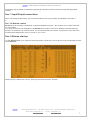
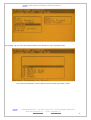
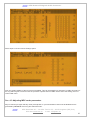
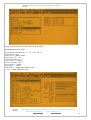
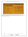
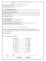
AEV Xtreme II Digital Audio Processor
AEV Xtreme II
Digital Broadcast Audio Processor
AEV Broadcast Srl – via della Tecnica 33 – 40050 Argelato (BO) Italy
Web site www.aev.eu
e-mail [email protected]
1
AEV Xtreme II Digital Audio Processor
Guarantee
The equipment is warranted for a period of 2 years from the date of invoice (ex-works). The
warranty does not cover faults provoked by carelessness, natural causes and parts subject
to wear. In addition, the cost of shipment is not covered. The warranty will be voided if the
equipment is mishandled.
Technical Support
If you require technical support, contact AEV SERVICE giving a clear and concise account of
your speciic problem. Quote the serial number of your equipment by referring to the AEV
nameplate attached to the equipment itself as this is the most important piece of information
to be provided.
Telephone: 39+051 892963 Fax: 39+051 893605
Factory Service and Repairs
If problems arise while the equipment is being installed, consult this manual and check that
the installation is being carried out properly. If the problems still cannot be solved, call the AEV
SERVICE Department for further information. If the problem is a minor one we can a telephone
call will probably sufice. If, on the other hand, the equipment is to be shipped to AEV for
service or repairs.
Shipping Instruction
When shipping the equipment to AEV, use the original package in order to be certain that it will
be fully protected during handling. If you need the original package, call us for a new one.
If you ship the equipment in a different packing container, take care to provide a double
package by interposing padding material between the two containers in order to fully protect
the equipment during shipment. The package should be marked “FRAGILE” in red.
IMPORTANT: Carefully read this paragraph as it contains important instructions concerning
operator safety and directions regarding the installation, operation and maintenance of the
equipment.
Failure to observe the safety instructions and information given in this manual constitutes an
infringement of the safety rules and design specifications provided for this piece of
equipment.
Futurcom Srl declines all responsibility if any one of the safety rules given herein is not
observed.
Futurcom Srl declines all responsibility if the end-user resells the product.
The equipment is to be used by people capable of operating it in a trouble-free manner and it is
assumed that they are aware of the following safety rules.
• Keep this manual with the utmost care and close at hand so that it can be consulted whenever
needed
• After unpacking the equipment, check it for condition.
• Avoid banging the equipment.
• The packing material (plastic bags, polystyrene, nails, etc.) must never be left within the reach of
the children, as these items are potential sources of danger.
• Do not use the equipment in places where the temperature is not within the recommended
range, as speciied by the manufacturer.
• Before connecting the equipment, make sure the nameplate specifications correspond to the
mains electricity supply (the nameplate is located on the equipment enclosure).
• Do not remove the sticker from the equipment as it contains important specifications and the
relevant serial number.
• To join the equipment to the mains supply, use the power cord purchased with the equipment.
• The equipment must be used only for the purpose it was designed for.
• Abuse or misuse of the equipment is extremely dangerous for people, pets and property. The
manufacturer declines all responsibility for damage and injury resulting from improper use and
mishandling.
• Certain basic safety rules must be observed when using electrical equipment, in particular: Never touch the equipment with wet and/or damp hands or other parts of the body.
AEV Broadcast Srl – via della Tecnica 33 – 40050 Argelato (BO) Italy
Web site www.aev.eu
e-mail [email protected]
2
AEV Xtreme II Digital Audio Processor
- Keep the equipment away from drops of water or sprinkling systems.
- Never use the equipment near high heat sources or explosive material.
- Do not introduce any extraneous matter into the equipment.
- Do not allow children or untrained people to use the equipment.
• Before cleaning or servicing the equipment outside, disconnect it from the supply and wait at
least 2 seconds before working on it, as recommended by current safety regulations.
• In the event of faults and/or improper operation, turn off the equipment, shut off the electrical
power and call your dealer.
• Do not attempt to make repairs and/or adjustments when covers/guards or circuit boards are to
be removed.
• Blown fuses inside the power supply indicate that there may be a fault in the power supply itself.
The fuses must be replaced by qualiied and authorised persons. It is advisable to call your nearest
dealer.
• Call your dealer for any repairs and be certain original spare parts are used.
Failure to observe this rule may adversely affect the safety level of your equipment.
• The equipment is to be connected to the mains supply and provided with adequate and eficient
earth conductors.
• The electrical wiring must be done in compliance with current electrical codes CEI 64-8 “Electrical
speciication for domestic buildings”.
• When installing, leave a clearance of at least 1 cm around the equipment to
allow air to pass freely.
NOTE. This piece of equipment has been manufactured to the highest standards of
workmanship. It must be used properly and serviced as recommended to ensure longterm dependable operation.
The installation must be done in order to be able to guarantee an easy access to the cable of
feeding.
The device of dissection of the equipment is the cable of feeding, so it must be unconnected from
the equipment every time it is necessary to do any type of maintenance.
AEV Broadcast Srl – via della Tecnica 33 – 40050 Argelato (BO) Italy
Web site www.aev.eu
e-mail [email protected]
3
AEV Xtreme II Digital Audio Processor
Contents
PRECAUTIONS.......................................................... 2
Contenents .......................................................... 4
Sec. 1 The Xtreme audio processor ................................... 5
Sec. 1-1 Full control of peak modulation ............................ 5
Sec. 1-2 Programmability ............................................ 5
Sec. 1-3 Input/output configurations ................................ 5
Sec. 1-4-1 Analogue inputs/outputs .................................. 5
Sec. 1-4-2 Digital inputs/outputs ................................... 5
Sec. 1-4-3 MPX outputs............................................... 5
Sec. 1-4-4 RDS input (optional) .................................... 5
Sec. 1-4-5 SCA input................................................ 5
Sec. 1-4-6 RDS output (optional) ................................... 5
Sec. 2 Positioning and initial pre-set of Xtreme II ................. 6
Sec. 2-1 Xtreme’s best position .................................... 6
Sec. 2-2 At first power-up ......................................... 6
Sec. 3 Input/Output connections .................................... 6
Sec. 3-4 Remote control ............................................ 5
Sec. 4 Xtreme start-up ............................................. 6
Sec. 4-1 Pre-enphasis .................... ......................... 8
Sec. 4-2 Adjusting the input level................................... 9
Sec. 4-3 Adjusting MPX coder parameters ............................ 10
Sec. 4-4 System menu options ....................................... 11
Sec. 4-4-1 Setting date and time.................................... 12
Sec. 4-4-2 Adjusting the display contrast........................... 12
Sec. 4-4-3 Lamp Timeout ............................................ 12
Sec. 4-4-4 Operate / ByPass ........................................ 12
Sec. 5 Edit Preset men.............................................. 13
Sec. 5-1 BRILLIANCE ................................................ 13
Sec. 5-2 HF CLIPPING................................................ 13
Sec. 5-3 PRESENCE .................................................. 13
Sec. 5-4 MID BASS BOOST ............................................ 13
Sec. 5-5 LOW BASS BOOST ............................................ 13
Sec. 5-6 BASS MATCHING ............................................. 13
Sec. 5-7 30Hz Hpf Filter ........................................... 14
Sec. 5-8 Voice Bass Boost ...........................................14
Sec. 5-9 Gate Threshold .............................................14
Sec. 5-10 AGC On Off ................................................14
Sec. 5-11 AGC Drive ................................................ 14
Sec. 5-12 AGC Release .............................................. 14
Sec. 5-13 Multi Band Drive ..........................................14
Sec. 5-14 Multi Band Release ....................................... 14
Sec. 5-15 Multi Band Clip .......................................... 14
Sec. 5-16 Final Clip Drive ......................................... 14
Sec. 5-17 Downward Expander ........................................ 15
Sec. 6 System Update................................................ 15
Sec. 7 Connection .................................................. 16
Sec. 7-1 Connection PC - RS232...................................... 16
Sec. 7-2 Sample connection Remote RDS .............................. 17
Sez. 7-3 Sample connection Remote................................... 17
Sez. 7-4 Sample connection Analog & AES/EBU ........................ 18
Sec. 8 Technical Data .............................................. 18
AEV Broadcast Srl – via della Tecnica 33 – 40050 Argelato (BO) Italy
Web site www.aev.eu
e-mail [email protected]
4
AEV Xtreme II Digital Audio Processor
Sec. 1 The Xtreme audio processor
The Audio Xtreme II processor is a complete audio signal processing system for AM, FM and TV transmissions.
The sound quality defines the station’s image and professionalism. The importance of the AUDIO PROCESSOR
is therefore clear. The wholly digital technology with which Xtreme II was built means that the results obtained
can IN NO WAY BE COMPARED with those of any other traditional processor.
The multi-band structure is the best way to process an audio signal; Xtreme II is based on five-band processing
of the audio signal, with a storage capacity equal to 82 different equalization curves, 64 of them editable.
Every curve has the facility for integral control of process parameters to give your station a competitive sound,
with extra power, continuity, presence and clarity, without “pumping” or other unnatural effects.
All of Xtreme II’s adjustments and operational sequences are distinctly shown on a high resolution LCD graphic
display and are facilitated by a guided menu showing the enabled functions at every programming step.
The equalization and compression curve trends are shown on the display, which graphically reproduces the
spectral distribution of the processed signal over 5 bars.
Sec. 1-1 Full control of peak modulation
Xtreme II provides full control of AM, FM and TV audio signal transmission levels and can interface with any
transmitter habitually used in any part of the world.
Xtreme II performs a high-precision peak control, restricting over-modulation level to just 0.3 dB !
The Xtreme II audio processor dynamically controls the pre-boost level, it can never be heard to operate, and
produces a clear, open, brilliant sound which improves the original program.
Xtreme II’s audio processing circuits produce a signal which is pre-boosted with 50 µs or 75 µs curves and is
controlled precisely and absolutely in order to avoid over-modulation; the signal is then filtered to protect the pilot
tone at 19 KHz. If the 2-channel signal output by the processor is inserted in an external stereo encoder, we
advise you not to place any element between the two appliances that could alter band width and enlarge
modulation peaks beyond average modulation levels. Otherwise, modulation level must be reduced to control the
highest peaks.
Low-pass filters, high-pass filters, transformers, distribution amplifiers, and long transmission lines, can all cause
the signal to alter. We advise you to by-pass any low-pass filter and pre-booster circuits present on normal stereo
coders; we should stress that these measures have already been adopted inside the processor.
Obviously the above criteria for optimal control of peak modulation levels can be satisfied more easily if the audio
processor uses the internal stereo encoder. In Xtreme, there are no circuit elements between the audio processor
and the internal stereo encoder that could cause wave shape distortions. We therefore advise you to use Xtreme
with its own builtin encoder whenever feasible.
Sec. 1-2 Programmability
Xtreme II is supplied with 18 program-resident equalisation curves; they help the user understand the
programming process. The remaining 64 curves are at the user’s disposal.
For specific programming operations, see the appropriate paragraph.
All programming operations can easily be directly retrieved by the operator, by using the “Jog” knob or by using
the “Planning” programming at exactly specified times.
Sec. 1-3 Input/output configurations
Xtreme II was designed to house the following simultaneously:
1. left/right analogue inputs and outputs
2. Standard AES EBU digital inputs and outputs
3. 2 composite stereo outputs (for FM version)
4. RDS input (if RDS coder option is not installed)
5. SCA input (for FM version)
6. RDS output (if RDS coder option is installed)
AEV Broadcast Srl – via della Tecnica 33 – 40050 Argelato (BO) Italy
Web site www.aev.eu
e-mail [email protected]
5
AEV Xtreme II Digital Audio Processor
Sec. 1-4-1 Analogue inputs/outputs
The analogue inputs are installed on two XLR female connectors, located on the rear panel. The input is ≥10
KΩ high impedance, and the inputs accept signals up to +12dBu. The analogue outputs are provided with two
XLR male connectors, located on the rear panel. The outputs can pilot loads of ≥10 KΩ.
Sec. 1-4-2 Digital inputs/outputs
The digital input is provided with an XLR female connector, located on the rear panel. Balanced input with a 110Ω
impedance. The digital output is provided with an XLR male connector, located on the rear panel. Impedance, as
for the input, is 110 Ω.
Sec. 1-4-3 MPX outputs
The stereo coder (optional) has two outputs on a non-balanced BNC connector, located on the rear panel. Each
outputcan be connected via a cable with maximum length of 3 mt, before any signal deterioration occurs.
The levels of the outputsare controlled by the “Jog” on the front panel.
Sec. 1-4-4 RDS input (optional)
The RDS input is active in the FM version, if the RDS internal coder is not installed. It is provided with a BNC
connector, located on the rear panel, with 10 KΩ impedance.
Accepted levels range between 0 and -14dB.
Sec. 1-4-5 SCA input
A non-balanced BNC connector, for use with the SCA signal, is also available on the input. It can accept any type
≥ of 23 KHz subcarrier. The subcarrier is mixed with MPX signals. Accepted levels range between 0 and -14dB.
Sec. 1-4-6 RDS output (optional)
The RDS coder (optional) has an output on a non-balanced BNC connector, located on the rear panel. The output
level is fixed at 0dBu. It is also present on the MPX+RDS output with a level which can be adjusted from - infinite
to -17.5dB.
Sec. 2 Positioning and initial preset of Xtreme II
Sec. 2-1 Xtreme’s best position
Xtreme II’s best position is as close as possible to the transmitter, so that the stereo encoder output can be
connected to the transmitter via a route causing minimal variation to the wave shape of the MPX signal.
Xtreme II outputs can pilot a coder with cable length of up to 3 m before any appreciable degradation of the MPX
signal is noted.
If this is impossible, the best solution is either to: power up an external coder located close to the transmitter
energiser via Xtreme’s base band analogue output, or to use the digital output with an essentially flat frequency
response plus a constant wave train delay in the range 30 Hz to 15 KHz.
To ensure maximum transmission quality, all appliances downstream of the studio must be carefully aligned and
must satisfy the appropriate standards for wave width, distortion, wave train delay and gain stability.
These appliances must be re-checked at reasonable intervals.
It is therefore important that the sound source connected to Xtreme II has low noise at output, the flattest
possible requency response and low distortion.
Sec. 2-2 At first power-up
Before powering up Xtreme II, make sure that mains power matches the value shown on the rear of the power
supply and hat the electric system to which Xtreme II is connected, is supplied with a good grounding system.
AEV Broadcast Srl – via della Tecnica 33 – 40050 Argelato (BO) Italy
Web site www.aev.eu
e-mail [email protected]
6
AEV Xtreme II Digital Audio Processor
The display may be difficult to understand at power-up, therefore, set the contrast level (see the appropriate
section)
Sec. 3 Input/Output connections
When connecting inputs/outputs, you are recommended to use a good quality, well shielded, soft cable. 0
0
Sec. 3-4 Remote control
Xtreme II can be remotely controlled via an RS-232 standard serial port – this enables you to control it via both
PC and modem.
A 15-pole connector is also available on the Xtreme II’s rear side to send on air 8 different presets simply by
means of a command of an external switch. For connection details, see section “Connections” at the end of the
manual Preset assignments occur by means of “TLC” menu.
Sec. 4 Xtreme start-up
To align Xtreme II with your system as the first operation, we advise you to recall one of the configurations preset
inside Xtreme II.
Starting from the initial menu “Home”, press Jog and enter the menu “Process”.
AEV Broadcast Srl – via della Tecnica 33 – 40050 Argelato (BO) Italy
Web site www.aev.eu
e-mail [email protected]
7
AEV Xtreme II Digital Audio Processor
By pressing Jog, you can select “Recall Preset”, then choose one of the 18 preset curves
At the end of the selection, return to Home menu by means of the “Back” option.
AEV Broadcast Srl – via della Tecnica 33 – 40050 Argelato (BO) Italy
Web site www.aev.eu
e-mail [email protected]
8
AEV Xtreme II Digital Audio Processor
Sec. 4-1 Pre-enphasis
Then select Pre-emphasis and choose Change option. By means of the Jog you can scroll the available options:
OFF, 50µS (European standard) and 75µS (USA standard).
At the end of the selection, return to Home initial menu.
Sec. 4-2 Adjusting the input level
Play a piece of music ( CD ) with good dynamics and a rich sound. Adjust the mixer to obtain 0dB indication on
the instruments. From now on, disable any equaliser from any mixer channel, with the exception of any
microphones only. Press Jog and select Input Preset.
AEV Broadcast Srl – via della Tecnica 33 – 40050 Argelato (BO) Italy
Web site www.aev.eu
e-mail [email protected]
9
AEV Xtreme II Digital Audio Processor
Select Input Level and choose Change option.
Now, the graphic display of the input level is available. This can be amplified or reduced of 12 dBu. By means of
the Jog select a gain in order to have the processor operate around 0 dBm. At the end of the setting, return to
Home initial menu.
Sec. 4-3 Adjusting MPX coder parameters
May we remind you again that any other pre-enphasis on your transmission chain must be disabled as it is
generated by Xtreme II. Press Jog and select Encoder.
AEV Broadcast Srl – via della Tecnica 33 – 40050 Argelato (BO) Italy
Web site www.aev.eu
e-mail [email protected]
10
AEV Xtreme II Digital Audio Processor
Below you will find the parameters that may be changed:
PARAMETER SELECTABLE VALUES
Configuratuon Left Right LR OFF - L OFF - R OFF - LR ON
Mode STEREO - MONO
Pilot Level OFF -28dB -18.4dB
Pilot Phase -15° ÷ +15°
Composite Clipper OFF - ON
Out 1 Level 0 ÷ +12dBu
Out 2 Config MPX - SYNC
Out 2 Level 0 ÷ +12dBu
SCA Input 0 ÷ -14dBu
RDS Input 0 ÷ -14dBu (without RDS coder)
-31.5 ÷ -17.5dBu (with RDS coder)
AEV Broadcast Srl – via della Tecnica 33 – 40050 Argelato (BO) Italy
Web site www.aev.eu
e-mail [email protected]
11
AEV Xtreme II Digital Audio Processor
Select the parameter to be changed and carry out the correct set-up by means of the Jog.
If you are varying a parameter, but you wish to return to the previously set value, a “X” is shown on the right of the
bargraph which not only stresses the control used, but it also goes off if the set value corresponds to the
parameter value before any change.
AEV Broadcast Srl – via della Tecnica 33 – 40050 Argelato (BO) Italy
Web site www.aev.eu
e-mail [email protected]
12
AEV Xtreme II Digital Audio Processor
Sec. 4-4 System menu options
System menu enables following set-up
PARAMETER SELECTABLE VALUES
Operate-ByPass OPERATE - BYPASS
Lenguage Select. ITALIANO - ENGLISH
Time & Date DAY MONTH YEAR HOURS MINUTES SECONDS
Contrast 0 ÷ 16
RS232 Selection XTREME - RDS
Default Preset ATTENTION. ONCE THIS CHOICE IS CONFIRMED, ONLY THE FACTORY
PRE-SET DATA ARE RE-SET
VERSION DISPLAY OF THE FOLLOWING PARAMETERS µP MSG DSP - SOFTWARE UPDATE
If you access the Update software option by mistake, by switching the machine off and on no change is carried
out.
To perform Updating, see the appropriate description at the end of the manual.
Sec. 4-4-1 Setting date and time
To set a new date and time, press Jog and enter the “System” menu. Then select Time & Date, select the value
to change and, turning the Jog, set the new data. By pressing Jog again, the following position is reached.
At the end of the operation, return to Home menu.
Sec. 4-4-2 Adjusting the display contrast
In System menu, select the option Contrast, then select by means of the Jog a value between 0 and 16 (0 = min.
contrast, 16 = max. contrast)
Sec. 4-4-3 Lamp Timeout
In System menu, select the option Lamp Timeout, then select by means of the Jog Edit, now if you select ON
after 15 sec the display become blank, if you select OFF nothing happend.
Sec. 4-4-4 Operate / ByPass
In System menu, select the option Operate-ByPass. Then select Edit, change the status and press the Jog. When
the arrow on the right of the bar disappears, the set-up carried out will be On Air.
AEV Broadcast Srl – via della Tecnica 33 – 40050 Argelato (BO) Italy
Web site www.aev.eu
e-mail [email protected]
13
AEV Xtreme II Digital Audio Processor
Sec. 5 Edit Preset menu
Through the selection of Process menu, recall the option Edit Preset. The following controls are available:
PARAMETER SELECTABLE VALUES
Brilliance
0 ÷ +6 dB
HF Clipping
0 ÷ +6 dB
Presence
0 ÷ +6 dB
Mid Bass Boost
OFF - 0 ÷ +12 dB
Low Bass Boost
OFF - 2MA ÷ 12 MA - 2MB ÷ 12 MB
Bass Matching
0% ÷ 100%
OFF - ON
30 Hz Filter
Voice Bass Boost
OFF - ON
Gate Threshold
OFF - 44 ÷ -15 dB
AGC
OFF - ON
AGC Drive
- 10 ÷ +25 dB
AGC Release
0 ÷ 20 dB/Sec
Multiband Drive
0 ÷ +25 dB
Multiband Release
FAST - MID FAST - MID SLOW - SLOW
Multiband Clip Drive
-4 ÷ +5 dB
Final Clip Drive
0 ÷ +5 dB
Downward Exp. Thr.
OFF -6 dB +12 dB
A Preset can be modified at will to obtain a different sound from each station.
Now a detailed description of the different settings.
Sec. 5-1 BRILLIANCE
Controls high frequencies and thus brilliance of the sound.
We recommend 3.0
Sec. 5-2 HF CLIPPING
Controls the timbre of high tones: either SOFT 0.0 or more cutting +6.0
We recommend 0.5
Sec. 5-3 PRESENCE
Controls medium frequencies whose range of values also includes voice signals.
We recommend 0.5
Sec. 5-4 MID BASS BOOST
Controls medium to low frequencies
We recommend 0.0
Sec. 5-5 LOW BASS BOOST
Controls low frequencies in two modes:
MODE A : Increases to obtain a peaking Bass
At full scale of MODE A there is automatic change-over to MODE B
MODE B : cancels mode A and increases a more muffled, softer bass.
Sec. 5-6 BASS MATCHING
Used to keep the Bass if Low Bass Boost is set high.
If low bass amplification is increased too much, sometimes the bass tends to go off its limit (it does not leave the
75KHz modulation. The off limits bass effect is purely an acoustic effect ).
By using this control, high percentages of Low Bass Boost can be obtained, however, keeping the bass always
under control.
Bass Matching 0% = Free bass
Bass Matching 100% = Bass tied to medium frequency
We recommend 30%
AEV Broadcast Srl – via della Tecnica 33 – 40050 Argelato (BO) Italy
Web site www.aev.eu
e-mail [email protected]
14
AEV Xtreme II Digital Audio Processor
Sec. 5-7 30Hz Hpf Filter
A filter which eliminates the “rumble” typical of turntables and feedback from speakers into the microphone.
We advise you to leave this ON
Sec. 5-8 Voice Bass Boost
Xtreme II is able to recognise the voice from the rest of the program and, thanks to this control, it activates a
pleasant full bodied, thrusting effect that is great to listen to..
This control is fully transparent during a music programme and, in any event, does not create anything artificial,
leaving a clean sound (both voice and music).
We advise you to leave this ON
Sec. 5-9 Gate Threshold
This prevents Xtreme recuperating ground noise during silent pauses, because, by switching on the GATED
indicator light on the display, it locks out the bands preventing the bands from gaining ground noise.
We recommend -45dB
Sec. 5-10 AGC On Off
Activates the input pre-leveller, without which Xtreme could change the timbre according to level.
Always leave it ON
Sec. 5-11 AGC Drive
For piloting AGC.
When the machine is aligned with respect to the mixer (see installation chapter), adjust this control in order to
“SQUASH” the AGC bar to -10 -15 dB in the event of a fully modulated programme ( 0 dB ON MIXER )
Sec. 5-12 AGC Release
For fixing the speed at which the AGC follows the sound.
1 slower (for a very classic, stable, original sound)
20 fast (for a full, dense, rich sound)
We recommend 10 - 15 dB/sec
Sec. 5-13 Multi Band Drive
The higher is the level, the more the sound is compressed and therefore less dynamic. This causes a higher
middle modulation.
Too much compression can, in time, cause tiredness while listening.
Optimal compression is in the range of -5 to -15 dB
We advise you to set this control between 10 and 15
Sec. 5-14 Multi Band Release
The moving speed of the 5 bars
Slow (a full, stable, but very peaceful sound)
Medium-Slow (a full sound suitable for general peaceful music)
Medium-Fast (a full sound suitable for all types of radio format)
Fast (a very lively, full sound, at range limit, suitable for radio rock – super hits)
We recommend Medium-Fast
Sec. 5-15 Multi Band Clip
This controls a circuit which clips the audio signal without introducing any distortion.
-4.0 (a more muffled, compressed, soft, opaque sound)
0.0 (an open, soft sound)
1.0 (a full sound with presence)
6.0 (an exasperated, plastic, synthetic, stretched, brilliant sound)
We recommend from 0.0 to 1.0
Sec. 5-16 Final Clip Drive
Control of final sound pressure.
AEV Broadcast Srl – via della Tecnica 33 – 40050 Argelato (BO) Italy
Web site www.aev.eu
e-mail [email protected]
15
AEV Xtreme II Digital Audio Processor
The sound is more or less amplified to reach a 75KHz maximum deviation
0.0 (the original process sound)
5.0 (an exasperated sound at the limit of the first distortion)
We recommend from 0.0 to 1.0 max
Sec. 5-17 Downward Expander
The noise (ground noise) reducer to be activated if using many tape supports or if the sources going on the air
carry ground noise (links, telephones, etc.).
When this control is activated, and providing there is no sound on one or more bands, the processor’s 5 bands
“close“ the ground noise by compressing it.
When sound returns, ground noise compression is immediately de-activated, with the bargraphs indicating the
actual classic compression.
OFF Disabled -7.0 Good noise filtering at normal level, excellent for all transmissions +8.0 Considerable filtering
due to substantial ground noise
We recommend -7.0 or OFF
Sec. 6 System Update
To update your Xtreme II, you need the following material:
1- Pc with a free serial port
2- Software to load the new updatings for Xtreme II
3- Updating files (updating file + file with Updating instructions).
If the above material is available, you can go on, otherwise you can contact the customer service.
Connect the serial cable between Xtreme II and PC.
By means of the RS 232 menu select the option XTREME.
At the end of these presets, you can arrange your Xtreme for the updating
From now on, follow carefully the instructions given by the updating program installed on your PC.
The non-compliance with these instructions may cause Xtreme to block. The block can be removed only at the
AEV customer service. If you access the Update software option by mistake, by switching the machine off and
on, no change is carried out.
Sec. 7 Connection
Sec. 7-1 Connection PC - RS232
AEV Broadcast Srl – via della Tecnica 33 – 40050 Argelato (BO) Italy
Web site www.aev.eu
e-mail [email protected]
16
AEV Xtreme II Digital Audio Processor
Sec. 7-2 Sample connection Remote RDS
AEV Broadcast Srl – via della Tecnica 33 – 40050 Argelato (BO) Italy
Web site www.aev.eu
e-mail [email protected]
17
AEV Xtreme II Digital Audio Processor
Sez. 7-3 Sample connection Remote
Sez. 7-4 Sample connection Analog & AES/EBU
OUTPUT
1 = GROUND
2 = INPHASE
3 = RETURN
INPUT
1 = GROUND
2 = INPHASE
3 = RETURN
Sec. 8 Technical Data
PERFORMANCE
Frequency response
Stop band rejection
Noise
Total distortion
Total system separation
30Hz ÷ 15 KHz (measured below compression and clipping THR)
> 78 dB beyond 17 KHz
> 75 dB in all conditions (depends on the processing parameters)
< 0,01 %
> 85 dB (30 Hz – 15 kHz)
ANALOG AUDIO INPUT
Configuration
Left and Right
Impedance
10 Kohm
CMRR
> 45 dB from 30 to 15 Khz
Sensitivity
±12dBu
Maximum input level
+16 dBu
Connector
XLR-type, female, EMI suppressed
Pin 1 Chassis
Pin 2 & 3 electronically balanced, floating and symmetrical
AEV Broadcast Srl – via della Tecnica 33 – 40050 Argelato (BO) Italy
Web site www.aev.eu
e-mail [email protected]
18
AEV Xtreme II Digital Audio Processor
ANALOG AUDIO OUTPUT
Configuration
Left and Right. Flat or pre-emphasized (50µS – 75µS)
Impedance
30 Ohm electronically balanced and floating
Minimum load impedance
600 Ohm
Maximum output level
+12 dBu into 600 ohm load
Connector
XLR-type, male, EMI suppressed
Pin 1 Chassis
Pin 2 & 3 electronically balanced, floating and symmetrical
STEREO GENERATOR
Configuration
Pilot freq.
Pilot injection
Distortion
Noise signal ratio
Stereo separation
Crosstalk Main to Sub
Crosstalk Sub to Main
38 kHz subcarrier suppression
76 kHz suppression
Composite audio level
Connector
Output impedance
Two outputs independent
19 KHz ± 0.001% Max over temp.
+4 ÷ 12 %
< 0.005 % @1 kHz
70 dB (Din Audio,Bypass mode) Typical
60 dB Typical
Great 48 dB 30-15 kHz
Great 46 dB 30-15 kHz
70 dB Typical
70 dB Typical
0 ÷ 12dB
BNC EMI suppressed
50 ohm
RDS GENERATOR
RDS signal
Standard specification EBU Doc. Tech. 3244-E and Cenelec PrEn 50067
Coding
Differential and Biphase
Modulation
DSB-suppressed carrier
Frequency
57 KHz
Bandwith
± 2.4 KHz
RDS output level
0 dBu (connector out MPX+RDS)
Connector
BNC EMI suppressed
DATA SYNCRHONISATION
Terminal Interface
RS232- at rear, asynchronous
Data Input
Full duplex
Format
Selectable
Transmission Speed
2400 ÷ 19600 baud
Connector
9 contact subminiature cannon female
RDS Data management Microprocessor controlled 128 Kbyte
Non volatile memory RAM data retention 10 years
REMOTE I/O
MS, TA, RDS OFF Cmos level
Connector 25 contact subminiature cannon female
SCA SUB-CARRIER INPUT
SCA input
Connector
Input impedance
OFF 0 ÷ -14 dB
BNC EMI suppressed
10 Kohm.
GENERAL SPECIFICATION
Power supply
Dimensions
Weight
87 ÷ 265 VAC, 50-60 Hz 60 VA
19’’ (48,3 cm) wide, 7’’ (17,8 cm) high, 15’’ (38,5 cm) deep. 3 Rack units
12Kg
AEV Broadcast Srl – via della Tecnica 33 – 40050 Argelato (BO) Italy
Web site www.aev.eu
e-mail [email protected]
19