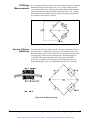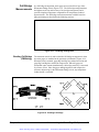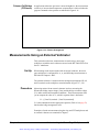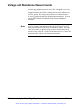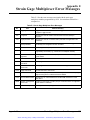
1
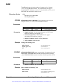
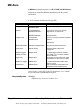
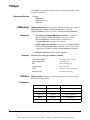
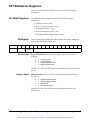
The WRITE
Registers
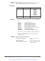
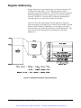
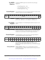
The following WRITE registers are located on the FET strain gage
multiplexer.
•
•
•
•
•
•
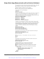
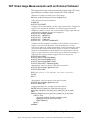
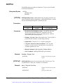
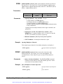
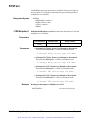
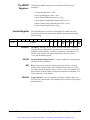
Control Register
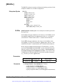
base + 0416
15
14
13
Write
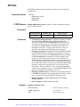
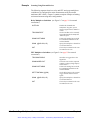
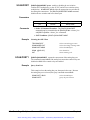
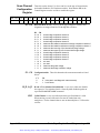
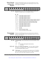
Control Register (base + 0416)
Scan Control Register (base + 0616)
Scan Channel Delay Register (base + 0816)
Scan Channel Configuration Register (base + 0A16)
Direct Channel Configuration Register (base + 0C16)
Direct Control Register (base + 0E16)
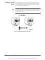
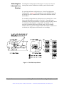
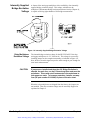
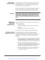
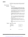
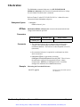
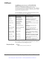
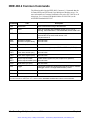
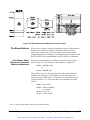
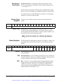
The Control Register is used to reset the multiplexer, enable interrupts,
choose direct or scan list control of the channels, and to internally trigger
channel closing.
12
11
Undefined
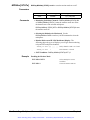
CRD RST
Appendix D
10
9
8
7
6
5
4
3
2
1
0
X
X
X
TRG
INT
DIR
IRQ
EN
X
CRD
RST
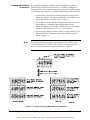
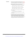
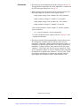
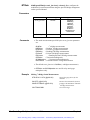
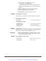
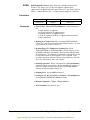
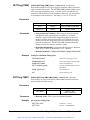
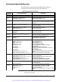
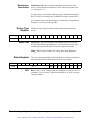
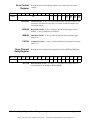
Card Reset. Writing a one (1) to bit 0 resets the multiplexer. Writing a
zero turns the reset function off. You must write a zero after a reset or the
multiplexer will not operate. The Reset conditions are: all enables are set
false (0), clear scan list, scan mode enabled (direct bit set 0), delay is
1 µsec and all channels opened.
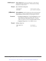
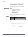
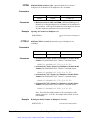
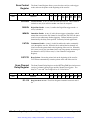
IRQ EN
Interrupt Request Enable (Write). A one (1) enables the card to generate
interrupts, a zero (0) disables it.
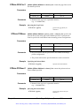
DIR
Direct. Selects between direct control and scan list control. A zero (0)
indicates scan list control and a one (1) indicates direct control. For scan
list control, the Direct Registers (base + 0C, base + 0E) are invalidated. For
direct control, the Scan Channel Configuration Register is invalidated. The
scan list, however, is not affected.
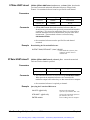
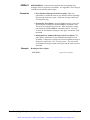
TRG INT
Trigger Internal. A one (1) immediately advances a channel on the scan
list, a zero (0) is the idle state. Bit is automatically set back to zero (0) upon
channel advance.
Strain Gage Register-Based Programming
Artisan Technology Group - Quality Instrumentation ... Guaranteed | (888) 88-SOURCE | www.artisantg.com
129