1
CRsOO DATALOGGER
OPERATORIS.MANUAL
11/96
COPYRTGHT (c) 1996 CAMPBELL SCIENTIFIC, lNC.
LICENSE FOR USE
This software is protected by both the United States copyright law and internationalcopyright
treaty provisions. You may copy it onto a computer to be used and you may make archival copies
of the software for the sole purpose of backing-up CAMPBELL SCIENTIFIC, lNC. software and
protecting your investment from loss. All copyright notices and labeling must be left intact.
This software may be used by any number of people, and may be freely moved from one
computer location to another, so long as there is no possibility of it being used at one location
while it's being used at another. The software, under the terms of this license, cannot be used by
two different people in two different places at the same time.
eAMPEIELL =IGIENTIFIG, ll\|C.
a15 W. 1800 N.
Logan, UT 84321-1744
USA
Phone (435) 753-2342
FAX (43s) 7sO-954O
www.camobellsci-com
Campbell Scientilic Canada Corp.
'|
1564 -149th Street
Edmontonr Albeda TsM 'lW7
CANADA
Phone (4O3) 454-2505
FAX (4O3) 454-2655
Camobell Scientilic Ltd.
14-2O Field Street
shepshed, Leics. LE12 gAL
ENGLAND
Phone (44)-50960-1141
FAX (44)-50960-1091
LIMITED WARRANTY
CAMPBELL SCIENTIFIC, lNC. warrants that the magnetic diskette on which the accompanying
computer software is recorded and the documentation provided with it are free from physical
defects in materials and workmanship under normal use. CAMPBELL SCIENTIFIC, lNC.
warrants that the computer software itself will perform substantially in accordance with the
specifications set forth in the Operator's Manual published by CAMPBELL SCIENTIFIC, lNC.
CAMPBELL SCIENTIFIC, lNC. warrants that the software is compatible with IBM PC/XT/AT and
PS/2 microcomputers and 100% compatible computers only. CAMPBELL SCIENTIFIC, lNC. is
not responsible for incompatibility of this software running under any operating system other than
those specified in accompanying data sheets or operator's manuals.
The above warranties are made for ninety (90) days from the date of original shipment.
CAMPBELL SCIENTIFIC, lNC. will replace any magnetic diskette or documentation which proves
defective in materials or workmanship without charge.
CAMPBELL SCIENTIFIC, lNC. will either replace or correct any software that does not peform
substantially according to the specifications set forth in the Operator's Manualwith a corrected
copy of the software or corrective code. In the case of significant error in the documentation,
CAMPBELL SCIENTIFIC, lNC. willcorrect errors in the documentation without charge by
providing addenda or substitute pages.
lf CAMPBELL SCIENTIFIC, lNC. is unable to replace defective documentation or a defective
diskette, or if CAMPBELL SCIENTIFIC, lNC. is unable to provide corrected software or corrected
documentation within a reasonable time, CAMPBELL SCIENTIFIC, lNC. will either replace the
software with a functionally similar program or refund the purchase price paid for the software.
CAMPBELL SCIENTIFIC, lNC. does not warrant that the software will meet licensee's
requirements of that the software or documentation are error free or that the operation of the
software will be uninterrupted. The warranty does not cover any diskette or documentation which
has been damaged or abused. The software warranty does not cover any software which has
been altered or changed in any way by anyone other than CAMPBELL SCIENTIFIC, lNC.
CAMPBELL SCIENTIFIC, lNC. is not responsible for problems caused by computer hardware,
computer operating systems or the use of CAMPBELL SCIENTIFIC, lNC.'s software with nonCAMPBELL SCIENTIFIC, lNC. software.
ALL WARRANTIES OF MERCHANTABILITY AND FITNESS FOR A PARTICULAR PURPOSE
ARE DISCLAIMED AND EXCLUDED. CAMPBELL SCIENTIFIC, INC. SHALL NOT IN ANY
CASE BE LIABLE FOR SPECIAL, INCIDENTAL, CONSEQUENTIAL, INDIRECT, OR OTHER
SIMILAR DAMAGES EVEN IF CAMPBELL SCIENTIFIC HAS BEEN ADVISED OF THE
POSSIBILITY OF SUCH DAMAGES.
CAMPBELL SCIENTIFIC, lNC. is not responsible for any costs incurred as result of lost profits or
revenue, loss of use of the software, loss of data, cost of re-creating lost data, the cost of any
substitute program, claims by any party other than licensee, or for other similar costs.
LICENSEE'S SOLE AND EXCLUSIVE REMEDY IS SET FORTH IN THIS LIMITED WARRANTY.
CAMPBELL SCIENTIFIC, INS.'S AGGREGATE LIABILITY ARISING FROM OR RELATING TO
THIS AGREEMENT OR THE SOFTWARE OR DOCUMENTATION (REGARDLESS OF THE
FORM OF ACTION . E.G. CONTRACT, TORT, COMPUTER MALPRACTICE, FRAUD AND/OR
OTHERWISE) IS LIMITED TO THE PURCHASE PRICE PAID BY THE LICENSEE.
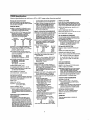
CR500 Speciflaolions
Electrical specifications are valid over a -25o to +50oC range unless otherwise sPecified.
PROGRAM EXECTITION
RATE
System lasks initiated in sync with feal-tim€ up to
I Fl& orle m€asuremont'wih data'trsnsler i8 pd;sible
at lhis ralo withoul in|erruplhn.
ANALOG INPIIS
NUMBER OF CHANNELS:2 difl€tential or up to 4
single-ended. Each dltferenlial channel can b€
contigured as two singl+€nded channols.
*2500
Ra€,olutic,,
3(l3
33.3
3.33
1.00
0.33
17.5
12.5
(yv)
2.OO
0.66
INPUT FREQUENCY RANGE:
-
INFUT SAMPLE RATES: The fast and dow A/D
convers'rons uee signal htegralion times of 0.25
and 2,72 tt18, respeclivelY.
voltage:
4.2 rni
Fast differentlal
Slow dilferentialvoltagel 9.2 m8
ms
toi€clion:
25.9
with
Hz
Difterential
60
INPUT NOISE VOLTAGE (fot r2.5 mV lang€):
Fasl differential: 0.82 PV RMS
SlorY diffoFntial: 0.25 FV RMS
Difierenlial with
60 Hz reiection: 0.1 I PV RMS
COMMON MOOE RANGE: t2.5 V.
OC COMMON MODE REJECTION: > 140 dB'
NORMAL MODE REJECTION: 70 dB (60 Hz wilh
slow ditf erential msasurgment).
tg
DEFINITION: Th€ tim€ period for a sp€cilied numbet
ol cycles of an input signal lE rnea8urcd, then
divid€d by the number ot c}ll€slo obtain the
averag€ p€dod ct a slngle clEle. lmpro\red
tming resolution and nois€ rsduction can be
obtainod by averaging o/er marry c)rcl€8.
INPUTS: Any of the 4 singas-iitded analog input
chann€|s can be s€l€cled tor pedod averaging.
Signal afiplitud€ rcd|.Iction or AC coupling i8
notmally roquircd.
666
66.6
6.66
ACCURACY OF VOLTAGE MEASUREMENTS AND
ANALOG OUTPUT VOLTAGES: t0.1% ol FSR;
* 0.05% of FSR, (0 to /O'C); (e.9., to.l% FSR
'*5.0 mV for r25O0 mV tange)
INPUT CURRENT:
-
DIOIIAL I/O PORTS
2 ports: Porl Cl is sollware seloclable a8 a binary
inpitt or control oulpuf. Port C?JHI b inpul only and
can be software configurod as en SDI-12 pon, a Unary input, ot a8 a switch closute counter (40 Hz max).
OUTPUT VOLTAGES (no load): high 5.0 v +0.1 v;
low < 0.1 V.
OUTPUT RESISTANCE: 5OO OhNS.
Dltlerentia! Single-Eded
t250
,25
ACCURACY: 10.02% ol lull scaleinpul range used,
limitod by tho matching bridgt€ r6istors (6.9.,
t0.02% of a250 mV tulFecale hput rango
r'l 0O trV). The sxcitatiof, rroltage 8hordd be
programmed so th€ bddge ouiput matches the
full scale hpul voltagp.angs.
PERIOD AVERAGING MEASUREME}IS
RANGE AND RESOLUTION: Ranges are software
selectable tor any chann€|. The resotution lor
diflerential measurements is better lhan
singleended moasuromenls because two
m€aSuroments arg av€rag€d tog€lher.
Fuil Scale
lnpd Range (mW
0.75 ms excitation pube lor ionic depoladzation;
signal integralion occurs o/er ths lagl 0.25 m8.
nA maximum.
INPUT RESISTANCE: 20 Gohms lypical.
EXCIIAT|ON Ot TPtlS
DESCRIPTION: 2 switched excilations, actve during
measurement, with one output active at a time' Nonactive outputs are high impdance.
RANGE: i2.5 V
RESOLUTION: 0.67 mV
ACCURACY: t2.5 mV (0'to lo'C);
*5 mV G25" lo +50'C)
OUTPUT CURRENT: t25 mA
FREQUENCY SWEEP FUNCTION: A swepl frequency, square wave output b€trwen 0 and 2.5
volt8 is provid€d lor vibrating wire transduceE'
Timing and lrequerEy range ate specified by lhe
instruction.
RESISIANCE AND CONDUCTIVITY
MEASUREMENIS
MEASUREMENT WPES: Using eith€r of the 2
switcied excitation channela, the CR500 can
rneasuro rosiatanc€ and conduclivily by means
of ratiometdc btidg€ moasuremenls. Standard
bridgo measurement8 include swire and 4-wire
full btidge, +wire, }wirc, and 2'wir6 haf b.idge'
where appropriat€, dual poladty btidg€ moasure'
m6nts are used lo elimihato OC onor8. AC
resistance ti€asurcm6nts use a dual polality
Renga Minwtts(peak+eak)
Co&
I
2
3
4
Frcq.'
2mV
smv
O Max,
Max. lnpd
fteqtencY
SkHz
20kHz
12mV
2000mV
40 kHz
150 kHz
ground.
must
be
c€ntered
around
CRsoo
'AC voltag€
RESOLUTION: 35 ns divided by the numb€r ol
cydes mea6ured.
INPUT STATE: high 3.0 V lo 5.5 V; ldt,
{.5
V to 0.8 V.
INPUT RESISTANCE: 100 kohm8.
SDI.I 2 INIERFACE STANDARD
This communlcatlon protocol, d€\relop€d tor micropaoc€$or-based hydrologb and environmental 9€nsors, i8 s*endad In the CR50O;
SENSOR CONNECTIONS: Digital UO Port Cl or C2
(tor asyncfi ronous cornnxJnication), 12V pow€r,
and ground. Up to ton SDI-I 2 senao|B can be
conn€cted to each CR5O0 digital port.
EMlond
ESD PROTECilON
Emigsions: Me€t6 of e)(coede lhe lollowing slan-
dafth.
Radiated; per EN 55022:1987 class B
Conducted: p€r EN 55022:1 987 Ctass B
lmmunity: MeetB or e)(ceeds lh€ follorving standaKb.
ESD: p€r IEC 801-2;1984 8kV ah discharge
ACCURACY: 10.01% of reading + RESOLUTION.
RF: per IEC 801-3:19&4 3V/m, 27'500 MHz
TIME REQUIRED FOR MEASUREMENT: Signal
p€dod multiplied by lhe numb€r ol clcles
measured plu8 1.5 qrcles.
EFT: p€r IEC 801-4; 1988
olher
lkv
mains,SooV
CPU AND INTERFACE
PUISE COUNIERS
PROCESSOR: Hitacii 63ff|.
NUMBER OF PULSE COUNTER CHANNELS:2
eight-bit or I sitteen-bit: sollware seleclable ag
switch dosure, high frequency pulse, or lo*level
AC. An additional channel (czP3) can be
sofiware contigured to read swilch dosurG at
rat68 up to 40 Hz.
MEMORY: 128 K Flash and 32 K SRAM standard.
MAXIMUM COUiIT RATE: t6 kHz, eight-Ul counlec
250 kHz, sixleen-Ul counter. Channela are
scanned at I or E4 Hz (softwate solectau€).
MODES: Swibh clcur€, high frequency pulso, and
low l€vol AC.
SWITCH CLOSURE MOOE
Minimum Swit€h Clooed Tim6:5 m8.
Minimum Switdr Op€n Tim€:6 rE.
Modmum Sounce Time: I ms open
without b€ing counted.
HIGH FREQUENCY PULSE MOOE
Minirnum Pulso Widlh: I u8.
Maximum Input F equency:500 kHz,
voltag€ Thresholds: Counl upon transition
fto.n b€low 1.5 V lo abo\re 35 V.
Maximrm Inpd Volag€: l20 V.
LOW LEV€LAC MODE
. (Typicalol magnetic pulse.tlow lranEducers or
other low voltage, sine wave oulpuls.)
Inpul Htstereds: I mV.
Maimum AC Input Voltag€: 20 V RMS.
Mininun AC lnpn Voltago Range (Hz)
(sine wave mV BMS)'
20
200
1000
'l6.tfi
t
to 1000
0.5 to 10,000
0.3lo 20.000
config. or A4 Hz 8ca4 ]9q'dlor treq . > ?o48 Hz.
DISPI-AY: 8 diglt LCD (0.5' digrts).
PERIPHERAL INTERFACE:9 pin D.type connoclor
for k€yboard disday, storage module, mod€m,
print€r, card olorage modul€, and RS-232
adapter. Baud rales s€l€clable at 300, 1200,9600
and 76,800. ASCII communicalim Plotocol is on€
Btart bit, one stop bit, eight data bils (no padly).
CLOCK ACCURACY:
il
minutc pet monh.
SYSTEM POWER REQUIREMENIS
VOLTAGE: 9.6 to 16 volts.
TYPICAL CURRENT DBAIN: I mA quiescenl,
13 mA during processing, and 46 mA dudng
analog maasur€filent.
BATTERIES: Any 12 voll battery can bo connected as
a paimary power source. Se\rsral porcr suPply
options are availabl€ kom Campbell Sci€ntific.
PHYSICAL SPECIFICATIONS
SIZE: 8.4' x 1.5' x 3.9' - Additional dearance
required lor CSI serial UO and 8€nsor leads.
WEIGHT:15 oz.
WARRANTY
Thr€e yea6 against def€cts in mat€rials and
uodmanshiD.
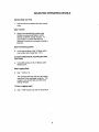
SELECTED OPERATING DETAILS
Starting Date and Time
1.
Date and time are stored with each output
afiay.
Data Transfer
2.
Short Cut automatically programs the
CR500 to dump stored data to a CSI
SM192 or SM716 storage module. To
output data to a printer requires the
technical manual and a program change in
EDLOG.
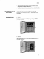
Erase Final Storage Data
3.
*A Mode, enter
ln the third window of the
(see
Sec. 7.5.1).
any number and A
Complete CR500 Reset, lnctuding the Real
Time Clock
4.
*A Mode, enter
ln the fifth window in the
98765 and A.
Stop Logging Data
5.
Key: *499A0A
This changes the scan rate to 0 and stops
execution of the datalogger program. The
program, any stored data, and the clock
setting remains.
To Start Logging Again
6.
Key: *4 99 A [new scan rate in seconds] A
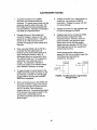
CAUTIONARY NOTES
1.
Voltages in excess of 5.5 volts applied to a
control poft can cause the CR500 to
malfunction. Voltages in excess of 8 VDC
can cause damage.
To prevent corrosion in the CR500,
desiccant must be placed inside the
enclosure. To reduce vapor transfer into the
enclosure, plug the cable entry seals. DO
NOT totally seal enclosures equipped with
lead acid batteries. Hydrogen concentration
may build up to explosive levels.
7.
Voltage pulses can be counted by CR500
Pulse Counters configured for High
Frequency Pulses. However, when the
pulse is actually a low frequency signal
(below about 10 Hz)AND the positive
voltage excursion exceeds 5.6 VDC, the 5
VDC supply will start to rise, upsetting all
analog measurements.
Damage will occur to the analog input
circuitry if voltages in excess of +16 V are
applied for a sustained period. Voltages in
excess of 15 V will cause errors and
possible overranging on other analog input
channels.
When using the CR500 with the PS12LA,
remember that the sealed lead acid
batteries can be permanently damaged if
deep discharged routinely or left in a
discharged state for a long period of time.
The cells are rated at a 7 Ahr capacity but
experience a slow discharge even in
storage. lt is advisable to maintain a
continuous charge on the PS12LA battery
pack, whether in operation or storage.
4.
Voltages in excess of 7 VDC applied to the
5 V port will damage the CR500.
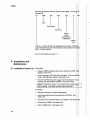
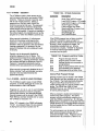
Pulses whose positive voltage portion
exceed 5.6 VDC with a duration longer than
100 milliseconds need external
conditioning. See below.
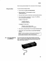
To make it easier to connect power to the
CR500 remove the green connector on the
terminalstrip. Connect 12 V and G in the
proper positions and plug the connector
FIGURE. Conditioning for Long Duration
Voltage Pulses
back into its receptacle.
When connecting power to the CR500 with
the green connector in place,lirst connect
the positive lead from the power source to
the 12 V terminal. Then connect the
negative lead to G. Connecting these leads
in the reverse order makes it easier for the
positive wire to accidentally touch a
grounded component and short out the
power supply.
ilt
cR500
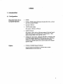
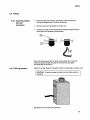
1. lntroduction
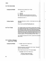
1.1 Configuration
Required ltems for a
Complete System
o
CRSoo
o
pC50O - CRsoo Support Software (includes Short Cut, a "point
and clicK program builder)
.
c
Operato/s Manual
'12
VDC power supply
CSI options: BPALK or PS12LA
.
sealed enclosure
CSI options: ENC 10/12 or CSI part number (P.N.) 6447 with 3
cable entry seals and a sealable vent to atmosphere. Other
options include ENC 1214 and ENC 16/18.
.
Option
o
Interface for user access. Either the CR1OKD or PO/laptop with
the SC32A optically isolated RS232 inter{ace and a 9 to 25 pin
cable (P.N. 7026). When using a battery-powered laptop
computer the SC929 cable can be used in place of the SC32A
and P.N.7026.
PC208 or PC208W Support Software
Supports telecommunications to retrieve data, monitor
measurements, set the clock, etc.
cRs00
Earth Ground
Each CR500 should
be tied to a good
earth ground.
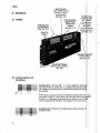
2. Hardware
2.1 CR500
Pulse Counters,
Digitallnputs
and Control
Output
(See Sec.2.3)
Analog Inputs
and Excitation
(See Sec.2.2)
Cable Tie
Circuit
polarity
(See
Downs
Campbell
9 Pin
(See
Mounting Flanges
(See Mounting Options,
Sec.6.2)
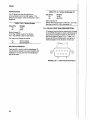
2.2 Analog Inputs and
Excitation
Analog Inputs: Terminals SE 1, 2 , 3, and 4 (labeled in light bl
are single-ended input channels. ln a single-ended measu
the voltage on an analog input is measured with respect to
DIFF
ground (AG).
Ll
rH
L 1J
sE12
When wired and programmed for a differential measurement,
2 are DIFF 1H and 1L. lnputs SE 3 and 4 are DIFF 2H and 2L
in white). ln a differential measurement, the voltage on the H
input is measured with respect to the voltage on the L (low) i
*;..,,,.
*i.#
tri........-
Analog ground: Reference for single-ended measurements
excitationreturn.
2.s)
cR50(r ''
Excitation channels: Provide a precision, programmable switched
voltage for sensors that require excitation. Range: t 0 - 2.5 VDC.
Power ground: Connect cable shields to this ground to minimize
electrical noise and protect against voltage transients. The main
grounding lug; labeted "earth ground", must be tied to earth ground.
Also used as excitation return for some sensors.
2.3 Pulse Gounters,
Digital Inputs, and
Gontrol Output
ffiffiffiffiffi
P2
Pulse Counters: To measure switch closures and voltage pulse
type sensors. P1 and P2 are programmable for switch closure,
voltage pulse, or low level,AO signals (see spec sheet on page i).
CAPT can be programmed to count switch closures at a rate up to
40Hz (see below).
Power Ground: Use as ground reference for pulse counters, binary
inputs, SDI-12 inputs, 12 VDC or 5 VDC outputs. Ground terminal for
cable shields to minimize electrical noise on sensor inputs and
protect against voltage transients. The main grounding lug, labeled
"earth ground", must be tied to the earth ground.
ffiffiffi
G
Digital UO Ports:
ffiffiffiffiffiffiffiffi1
c1 c2
Port Cl: When configured as input can be programmed as an
SDI-I2 communication line orto read the status of a line.
P3
When configured as output can be set high (5 VDC) or low
(0 VDC) according to time or a condition. Typically this port can
be used to activate an external device (e.9., a sampler) through a
relay.
Port C2lP3: Dualfunction controlled by CR500 program.
-
C2:- Input only.-SDl-1'2'communieation line or monitoring
the status of a line.
P3: Port can be programmed to count switch closures up to
4AHz. Example: tipping bucket rain gauge.
cR500
,
.'r*.
: ::l:l:jj
fil;1t,ii..'*l;;"#
l::, '.i t,l:j:f;fi;,r;,''.:'.,,,j,j;,.,,,,,,r1::
: ::::
,ml+r**,ffiim*iii#l#,
5 VDC: Provides power for external devices. Example:
to a tipping bucket rain gauge being read by port P3.
,,,,;''",:i +:r.L.r..;;,,ii ;i;l::.t'',:, ;:,.t;,:.,:.;
12
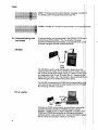
2.4 Communicating with
the CR500
VDC: Providbs 12 V for SDI-12 communication or for
An externaldevice must be connected to the CR500's CS l/O
communicate with the CR500. This may be either Campbell
Scientific's CR1OKD K€yboard Display, a computer/terminal, or
of several Campbell Scientific modemsfinterfaces.
CRlOKD
Cable
The CR1OKD is used to verify field operation, display incoming
measurements (*6 mode), view or set the clock (.5 mode), vi
set *4 values, display final storage values (.7 mode) and view
and diagnostics in the *A and *B modes (Sec. 5).
done in Short Cut (Sec. a.3). The program is then downloaded
CR500 through a PC to CR500 link as shown below.
The CR1OKD is powered by the CR500 and connects directly
9-pin serial l/O port via the SC12 cable (supplied with the CR1
No interfacing software is required.
PC or Laptop
Computer to CR500 communication is accomplished using
Campbell Scientific's PC500 or PC208(W) support software
packages. PC500 requires a direct link (SC32A or SC929),
PC2OB and PCZOBW accommodate all CSI telecommunication
interfaces (phone, radio; cellular, etc.). Connect the RS232
the PC's serial port (usually a male 9 pin connector).
cR500
power
Requirement
2.S CRS00
The CR500 operates at 12 VDC (nominal). Below 9.6 or above
cR500 will not operate properly. see section 6.5 for
1:.Y,o,:,the
oetails.
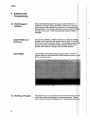
3. Internal Memory lllff,Etl1tfiisof
Used for running datalogger programs.
32K SRAMI
12gK Flash
has 32Kof sRAM and 128Kof non-voratire
Memorv
-
The Flash memory stores the operating system, user programs, and
final storage data.
Breakdown of Flash memory:
Maximum
Storage
Data
o
o
48K for operating system and datalogger program instruction set.
o
64K for final storage data. Four 16K sectors. Data are written to
memory one reading at a time. When memory is full, the 16K
sector with the oldest data is completely erased. Then new data
is stored in that sector.
16K for storage of both active and standby user programs.
*D
Several programs can be stored and later recalled using the
mode. See Section 7.5.4.
When allthree sectors are full, the CR500 will have over 32,000
readings'
When the next reading must be stored, the oldest 16K sector is
erased and then the reading is stored. At that point, the CR500 will
have just over 24,000 readings in final storage.
For more information on the CR500 memory, see Section 7.2.
cR500
4. Software and
Programming
+.1 PC500 Support
Software
Mouse' driven, [email protected] ram that supports basic CRSOO-Io-PC
operations including program generation, monitoring of real-ti
measurements, data retrieval over a direct link, and simple
table generation. For operation without a mouse, use the ALT
activate the menu bar. Telecommunications requires PC208 or
PC208W..
Install PC500 and
Short Cut
You have two dlskettes: PC500 and Short Cut. Place the
diskette in the A: drive slot and change to the A: drive. At the
prompt type "install" and press <Ente>. The installation
take you through the process including asking for the Short Cut
diskette when needed. lt will also create a PC500 directory.
Start PC500
Type "PC500" at the DOS prompt and press <Ente>. After the
program loads you will see the main PC500 screen and menu.
OK to remove the note.)
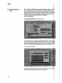
4.2 Building a Program
Using Short Cut, you can select sensors and measurements,
output data, create wiring diagrams, and prepare reports.
refer to sensor manuals for installation and maintenance
cR500
Starting Short Gut
ln the PC500 menu, choose File. ln the File menu, Short Cut. We
will abbreviate these directions from here on, e.9., FilelShort Cut.
Creating the CR500
Program
Short Cut leads you through four easy steps.
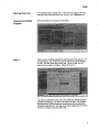
Step
Open a new or existing program by selecting one of the options. For
a new program, use a name that can be used for the station/logger
as well. The site name often works well. Short Cut will use this
name for the program it creates. Select OK to go on.
1
Two files are needed for each site. One will be the CR500 program
created by Short Cut. The other, the station file (Sec. 4.3) contains
the information PC500 requires to communicate with an individual
CR500 at a specific site. Use the same name (ideally the site name)
for both the program and the station file.
cR500
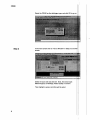
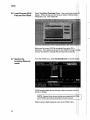
Select the CR500 as the datalogger type, and click OK to go on.
Step 2
In the main screen click on <Go to Window> in Step 2 to see
screen:
1111:1:1::::ljij:::i:l:!i
llllilllilill: llliii:
lllillil:1:111: lj:i::
Illilinrljii$iiii:
Select the scan rate and click OK. Next, the sensor type:
Meteorological, Level/Stage, Water Quality or Custom.
Then highlight a sensor and click add to select.
cRs00
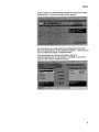
In this example, the 1078 has been selected from the group of water
quality sensors. A sensor information screen appears.
For most sensors you must furnish some configuration information.
Short Cut will prompt you for the required information. ln this case, the
user has selected an output in degrees Celsius. After this selection the 107B can be added to the list of
sensors/measurements for this program. Click Add. lf you wish to
measure other sensors, repeat the process
cR500
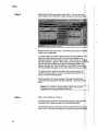
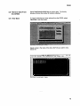
Step 3
After selecting all of your sensors, click Close. Then on the
screen select <Go to Window> in Step 3 to see the following
Select Intervals and Output Data. Select the processing and
output for your application.
You may specify up to three output reports and output intervals.
select the output report you want to work with among the three
cascaded windows. The hot keys are Alt-1, Alt-2, and Alt-3.
the output interval, if desired. Next, select a
the list on the left followed by the type of processing desired (
sample, average, etc.)from the buttons in the middle of the
The output labels willappear in the report window as they are
The data output for each interval starts with an arcay (report) lD
number and a time stamp. lf you do not add measurements to
report, the report will be disabled.
In this example a 15 minute average of the water temperatures
measured every 60 seconds has been selected. Click Close
done.
NOTE: lt is prudent to output battery voltage and program
signature once a day (see Output Table 3).
Step 4
Select <Go to Window> in Step 4.
Save the program and view or print wiring diagrams, data labels
monitoring, the *4 table (see Sec. 6.9), and list output data.
Use the check boxes on the right screen to select the i
wish to view. All of this information can be printed by selecting
10
cR500
Ground Connections
Analog Channels and Wiring Connections
Excitation Channels and Wiring Connections
When done, select Close then Exit.
11
cR500
4.3 Greate a Station
File
After creating a CR500 program, the next step is to create a
file. A station file contains the information PC500 requires (e.9.,
station name, COM port on your PC, the communications
and baud rate) to communicate with a specific CR500. When u
PC500 the interface type is the SC32A. There are several
interface options when using PC208 or PC208W for
teleeornmunications,
Select FilelNewlStation to see this screen:
ln most cases you can accept all the default settings. However,
may have to choose a different COM port to match your PC.
the .DLD file (the program created by Short Cut) to associate
station. When station parameters have been set, select "Save".
You willsee this screen:
Use the same name for the station file as that chosen for prog
Short Cut (eight characters maximum). Select OK.
12
cR500
5. Dry Run
5.1 Build a Program
5.2 Create a Station
File
5.3 Wire the Sensors
and Make PC
Connections
Before going into the field, go through a practice setup in the office.
Use Short Cut to generate a CR500 program, called a .DLD file. Use a
name for the program that can also be used to identify the site (Sec' 4.2)'
Using PC500, create a station file (.STN) to identify the site and the
CRSOO. Use the same name you used for the program (Sec' 4.3).
Wire the sensors to the CR500 using the wiring diagram created by Short
Cut (Sec. 6.4.2).
Connect the CR500 to the compute/s serial port' For a PC, use the
SC32A. For a battery-powered laptop, use either the SC32A or the
sc929.
5.4 Power the CR500
WHEN THE WIRING lS COMPLETE, connect the power supply to
the CR500, turn the switch on the PS12LA to ON or plug in the white
connector on the BPALK (Sec. 6.5). Connect the CR500 to the PC
using either the SC929 or SC32A interface.
5.5 Set the CR500 Clock
Select ToolslClock SetlChk to see this screen:
Select Set. Then Close.
13
cRs00
5.6 Load Program (DLD
File) lnto the CR500
Select ToolslSend Datalogger Prog. A pop up warning
appear. lf there is data you want to save, retrieve it before
ahead (Sec. 5.8). Then select OK.
Make sure the correct .DLD file is selected then select OK to
download. The program will be sent to the CR500 and begin
and you will receive a message the download was successful.
5.7 Monitor the
From the PC500 menu. select RealtimelMonitor to see this
Incoming Measurements
PC500 supports'data retrieval through a direct connection with
SC32A or SC929.
When finished, select Escape to return to the PC500 menu.
14
cR500
5.8 Retrieve Data From
the CR500
5.9 View Data
Select DataCollectionlOall Now to retrieve data. The Activity
Window will show the number of locations collected.
To view the data that you have retrieved from the CR500, select
ViewlData to see this screen:
Select or type in the name of the data (.DAT) file you wish to view.
Select OK.
Fi
Datacollection
le
ut"'
ottl,,,lfl':ii
jfi!:l?'riiil::ir,lrr:;,1,,1:::,::,,;:r:i,:,,:i
irir
ili:iiii:j
.i::ii
Close H.
Help
15
cRs00
Finalstorage data are stored in arrays in the CR500. The
the arrays is:
111 ,
1996
,
193
1100 ,
23;4
day of year
clock time
datum:
water
temperature
in degrees C
Array lD. Used to identify and segregate arrays stored at
output (time) intervals. Short Cut allows 3 output options and 3
f
D's:
1
'11, 222, and 333.
For more information see Sec.7.4.
6. Installation and
Maintenance
6.1 lnstallation Check List
ln the office:
o
Create a CR500 program (.DLD) and a station file (.STN).
Sections 4.2 and 4.3.
'Load
the program (.DLD file) into the CR500. (This can
done in the field with a laptop.) See Section 5.6.
Mount the CR500 and power supply into the enclosure. Do
transport with the batteries installed in the power supply.
NOTE: In Short Cut, Step 4 is a summary list and a list of
input locations. Print these and take them to the field.
ln the field:
16
a
Mount the enclosure. Install the battery(es).
a
Install a good earth ground connected to the CR500. See
Section 6.3.
a
Installthe sensors and wire them to the CR500. See
a
Power up the CR500. See Section 6.5.
a
Set the CR500 clock. See Section 5.5.
cR500
Verify reasonable measurements are being made and data are
being stored. See Sections 5.8 and 5.9.
lnstallfresh desiccant in the enclosure and close and latch the door.
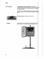
6.2 Protection From the
Environment
To protect the CR500 from moisture, dirt, insects, etc., use a
weatherproof enclosure with desiccant. Examples show CSI
P.N. 6447, a 10" x l2" fiberglass enclosure. Several other models
are available.
Mounting Options
A.
Standard
Note the ground wire (12 or 14 AWG) from ground lug on CR500 to
ground lug in enclosure.
B.
Alternate
Note the ground wire (12 or 14 AWG) from ground lug on CR500 to
ground lug in enclosure.
17
cR500
6.3 Grounding
The CR500 MUST be tied to earth ground. lt is the use/s
responsibility to provide this earth ground. The UTGND
can be purchased from CSl. lt includes a lightning rod,
rod, cable, and clamps.
Allcomponents of a system (datalogger, external power
mounts; housings;,etc.) should be referenced to ONE common
ground.
Main grounding
Example
18
lug:
Must be tied to earth ground.
Drawing of open enclosure, CR500, power supply and wiring to
good earth ground. A 12 AWG (or larger) wire should be used.
cR500
6.4 Wiring
6.4.1 Inserting cables
into the
enclosure
Open the cable entry seal on the bottom of the enclosure by
turning the squeeze nut (1) counter cloclaruise.
Remove and save the plug (2) tor further use.
Insert the wire (3) into the enclosure the required length and then
hand tighten the squeeze nut (clockwise).
-w=
l-=--l
#.
EI
Nla^\
,RY | \\).,
Gy.-
6-1
.|%r#
_
(
When using enclosures with an open conduit entry hole, insert the
wires the required length and seal the hole with the duct putty
furnished with the enclosure.
6.4.2 Wiring sensors
Follow the wiring "diagram" created by Short Cut (see Step 4, Section 4.2).
CAUTION: To ensure proper connection do not clamp over the
insulation.
Enlarged view of a single wiring terminal.
19
cR500
6.5 Powering the CR500
WHEN THE WIRING lS COMPLETE, including proper grounds,
the switch on the PS12LA to ON or plug in the white connector
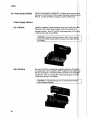
BPALK. Use the CR1OKD or a laptop to set the CR500 clock.
Power Supply Options
6.5.1 BPALK
Install the I alkaline D cells according to the "map" inside the
Place the holder inside being careful to route the connector wire
through the notch. Wire 12 V and #:to the power plug (12 V
on the terminal strip on the CR500.
CAUTION: Connect the white connector ONLY when
power the CR500, usually after the sensors have been
the CR500.
6.5.2 PS12LA
Be sure the PS12LA is being float charged by either the AC
or a solar panel. Turn the switch to OFF. Installthe 7 Ahr
the case as pictured. Connect the white connector to the
marked lNT. Wlre 12 V and G 1::#l1to the power plug (12 V and
on the terminalstrip on the CR500.
CAUTION: To prevent damage, do not transport the PS1
with the battery installed.
20
l
cRs00
6.6 Setting the Clock in
the CR500
Using a PC or
LaptOp
usins the cR1oKD
From the main menu in PC500 select ToolslClock SetlChk. PC500
will set the CR500 clock to that of the PC or laptop.
the cR500 must be terminated
3J,T#Hi;tl*?:H:TJi:S;ff*
Kev ln
lD:Data Exolanation
*5
:HH:MM:SS Displays current time
A
O5)<xxx Displays year
year
A
O5:xxxx
Enter the correct year and then
displays the day of the year window.
day of year
(see table, Sec. 7.7)
A
OS:HH:MM:SS Enter the correct day-of-year and
displays hours/minutes.
hours & minutes
(24 hour clock)
A
:HH:MM:SS
Enter the correct time (24 hour
clock).
6.7 View the
Measurements
USing a
Laptop
-
In the PC500 main menu, select Real TimelMonitor. When finished,
select Escape.
Select RealTime/Hang Up Link.
Using the
CRlOKD
Key In: *6 [location #] A
Otherkeys:A-advance
B - back up
The location is the input location found in the Short Cut list.
When finished, besure to key in *0.
21
cR500
6.8 View Stored Data
Using the GR1OKD
Stored data can be verified in
Key
A
B
#A
#B
ln:
the'7 mode.
*7 A
- advances
- backs up
- advances to the same element in the next array
- backs up to the same element in the previous array
See Sections 5.9 and 7.4.
Using a Laptop
First collect the data to a .DAT
file.
In the PC500 main menu.
ViewlData.
When finished, select RealTimelHang Up Link.
6.9 The *4 Table
The "4 table provides an easy method to change certain values
your CR500 program (DLD file). An example of when this is
is the setting of an olfset in the field at a stream gauging
Short Cut selects certain values a user might want to change
assigns them to the "4 table. Examples are the calibration
for a pressure transducer or the scan rate (program execution
interual). Find the *4 table with its labels by going to Step 4 in
Cut (for the specific .SCT file) and clicking on "Star 4 Entries".
The *4 table has locations from 0 to 99. Location 99 is
the scan rate.
6.10 To View or Change a
Value in the *4 Table
Using the CRlOKD
.
To view a value in the *4 table, key in:
"4 flocation numberlA
"Fressing-A.advances to.next location in the'4 table. Pressing
backs up to the previous location.
When finished, be sure to key in *0 to resume logging.
o
To change a value in the *4 table, key in:
*4
flocation numberl A [new value]
A if a positive number, CA if negative
22
cR500
When finished, be sure to key in *0 to recompile and resume logging.
Using a Laptop
To enter the Remote Keyboard State
r
o
.
.
From the menu in PC500 select RealTimelCall.
*" in the message box, select
When you see the
ToolslTerminal Mode.
Press the "Ente/' key two or three times to see the asterisk returned.
Key in 7H and "Ente/ to receive the ">" prompt. The CR500 is
now in the Remote Keyboard State.
To view a *4 value, key in:
'4 flocation number]A
A advances, B backs up.
To change a *4 value, key inl
*4
flocation number]A [new value]
A if the new value is positive, CA if negative
.
.
When finished, be sure to key in *0 to recompile and begin logging.
Select Close to exit Terminal Mode and select Real TimelHang
Up Link.
NOTE: In the Terminal Mode, communications will "time out"
and stop after 45 seconds in which no key is pressed.
6.11 Ghanging Batteries
iN thE BPALK
Connect the backup power before disconnecting the main power
supply. This will ensure the CR500 clock continues with the correct
time. In the event of a power failure the data and the program ARE
saved, but the clock is reset to 0.
23
cR500
6.12 Troubleshooting
Make sure the battery has been installed, and the power
No Response From
Datalogger Using
CRl OKD
"oN".
Use a voltmeter to measure the voltage on the 12 V and G
terminals on the datalogger; the voltage must be between 9
and 16 VDC.
c.
Disconnect any sensor or peripheral wires connected to the
and 12 V terminals.
D.
Disconnect any communications or storage peripherals
datalogger;--.*
E. Reset the datalogger
by turning the power switch to "OFF",
to "ON".
F.
24
lf still no response, callCampbell Scientific.
cR500
No ResPonse From
Datalogger Through
SC32A, SC929, or
Modem Peripheral
At the datalogger:
A.
Make sure the battery has been installed, and the power switch is
;bru;(bection z.s ano o.s).
B.
Use a voltmeter to measure the voltage on the 12 V and G
terminals on thedatalogger;the voltage must be between 9.6
and 16 V DC.
C.
Make sure the datalogger is connected to the modem, and the
modem is properly configured and cabled. See appropriate
peripheral manual.
D.
Make sure the Station File is configured correctly (Sec. 4.3.)'
E.
Check the cable(s) between the serial port and the modem. lf
cables have not been purchased through Campbell Scientific,
check for the following configuration using an ohm meter:
25-pin serial port:
computer
end
modetnqd
2
3
7
2
20
20
3
7
9-pin serialport:
end
23
32
420
57
comouter
-gg9gg Displayed In
Input
tocaiion
modem end
F.
Make sure the modem is properly configured and cabled. See
appropriate peripheral manual.
G.
lf still no response, callCampbell Scientific.
is between 9.6 and 16 VDC. Use
An A. Make sure the battery voltage
vortase between the 12 V and G
Afi',t#iJTi?#"ff!t?:he
B.
Verify the sensor is wired to the analog channel specified in the
measurement instruction.
C.
Make sure the Range parameter in the measurement instruction
covers the full scale voltage output by the sensor.
25
cR500
Unreasonable Results
Displayed in an Input
Location
6999 or 99999 Stored in
Final Storage (or
Storage Module)
26
A.
lnspect the sensor for damage and/or contamination.
B.
Make sure the sensor is properly wired to the datalogger.
c.
Check the multiplier and offset parameters in the measu
instruction.
Final Storage format limitations exceeded (any number
than 6999 in low resolution, or 99999 in high resolution
stored as the maximum number). Change the datalogger
program.
cR500
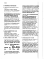
7. ADDITIONAL
INFORMATION
7.1 COMMUNICATING WITH THE
CRsOO
7.1.1 CRlOKD KEYBOARD/DISPLAY
The SC12 cable (supplied with the CRlOKD) is
used to connect the Keyboard/Display to the 9
pin CS l/O port on the CR500.
7.1.3 KEY DEFINITION
Keys and key sequences have specific
functions when using the CR1OKD keyboard or
a computer/terminal in the remote keyboard
state. Table 7.1-2lists these functions. In
some cases, the exact action of a key depends
on the mode the CR500 is in and is described'
with the mode in the manual.
lf the Keyboard/Display is connected to the
CR500 upon power up, the "HELLO" message
is displayed while the CR500 checks memory.
The totalsize of memory is then displayed (160
for 160 K bytes of memory). When the
CR1OKD is plugged in after the CR500 has
powered up, the display is meaningless until "xo
is pressed to enter a mode.
7.1.2 FUNCTIONAL MODES
CRSO0/User interaction is broken into different
functional MODES (e.9., setting time, inserting
*4 value, manually initiating a block data
transfer to Storage Module, etc.). The modes
are referred to as Star (*) Modes since they are
accessed by first keying *, then the mode
number or letter. Table 7.1-1 lists the CR500
Modes.
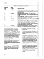
TABLE 7.1-1. * Mode Summary
Key
trE
trtr
trtr
trE
Mode
LOG data and indicate active Tables
These are program tables. They are
NOT typically used since the CR500
is most often programmed in Short Cut.
NOTE: Altering any value in these program
tables and compiling the program willerase
the *4 table in the CR500.
trtr
trtr
trE
trE
trtr
trE
trE
trtr
tru
trtr
TABLE 7.1-2. Key Description/Editing
Functions
@
Action
tr'tr
tr
E
tr
E
E
tr
trE
trtr
EE
trE
Key numeric entries into display
Enter Mode (followed by Mode
Number)
Enter/Advance
Back up
Change the sign of a number or index
an input location to,loop counter
Enter the decimal point
Clear the rightmost digit keyed into
the display
Advance to next instruction in
Program table (*1, *2, *3) or to next
Output Array in Final Storage (*7)
Back up to previous instruction in
program table or to previous Output
Array in FinalStorage
Delete entire instruction
(then A or CR) Back up to the start of
the current array.
When using a computer/terminalto communicate
with the CR500 (Telecommunications remote
keyboard state) there are some keys available in
addition to those found on the CR10KD. Table
7.1-3 lists these keys.
TABLE 7.1-3. Addational Keys Allowed in
Parameter Entry Table
Display/set real time clock
Display/alter lnput Storage data,
toggle flags or control ports.
Display Final €torage data
Final Storage data transfer to peripheral
Memory al location/reseVerase data
Signature/status
Security
Save/load Program
Used with TGT1 satellite transmitter
Telecommunications
Key
CR
:
S or^S
C or
aC
Action
Change Sign, Index (same as C)
Enter/advance (same as A)
Colon (used in setting time)
Stops transmission of data (10
second time-ouu any character
restarts)
Aborts transmission of Data
27
cRs00
7.1.4 USING COMPUTER WITH DATALOGGER
SUPPORT SOFTWARE
Direct datalogger communication programs in
the datalogger suppolt software (PC208E,
PC500, TCOM datalogger session) provide a
menu selection of tools to perform the
datalogger functions (e.9., set clock, send
program, monitor measurements, and collect
data). The user also has the option of directly
entering keyboard commands via a built-in
terminal emulator (Section 7.1.5).
When using the support software, the
computer's baud rate, port, and modem types
are specified and stored in a file for future use.
The simplest and most common interface is the
SC32A Optically lsolated RS232 Interface. The
SC32A converts and optically isolates the
voltages passing between the CR500 and the
external terminal device.
The SC12 Two Peripheral cable which comes
with the SC32A is used to connect the CS l/O
port of the CR500 to the 9 pin port of the SC32A
labeled "Datalogger". Connect the
"Terminal/Printer" port of the SC32A to the
serial port of the computer with a straight 25 pin
cable or, if the computer has a 9 pin serial port,
a standard 9 to 25 pin adapter cable.
7.1.5 ASCIITERMINAL OR COMPUTER WITH
TERMINAL EMULATOR
Devices which can be used to communicate
with the CR500 include standard ASCII
terminals and computers programmed to
function as a terminal emulator.
To communicate with any device other than the
CR1OKD, the CR500 enters its Telecommunications Mode and responds only to valid
telecommunications commands. Within the
Telecommunications Mode, there are 2 "states";
the Telecommunications Command state and the
Remote Keyboard state. Communication is
established in the Telecommunications command
state. FC500 usesthese commands to
accomplish its functions. One of the commands
is to enter the Remote Keyboard state.
The Remote Keyboard state allows the
keyboard of the computer/terminal to act like
the CR1OKD keyboard. Various datalogger
modes may be entered, including the mode in
which programs may be keyed in to the CR500
28
from the computer/terminal. Entering the
remote keyboard state is described in Section
6.10.
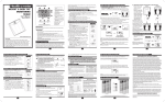
7.2 MEMORY AND PROGRAMMING
CONCEPTS
'22:1
|NTERNAT. MEMORY
The skndard CR500 has 128 K of Flash
Electrically Erasable Programmable Read Only
Mernory (EEPROM) and 32 K Static Random
Access Memory (SRAM). The Flash EEPROM
stores the operating.system, user programs,
and Final Storage data. RAM is used for
running the program.' The use of the Input,
Intermediate, and Final Storage in the
measurement and data processing sequence
shown in Figure 7.2-1. The fourareas of
are:
1.
System Memory - used for overhead
such as compiling programs, transferring
data, etc. The user cannot access this
memory.
2.
Program Memory - available for user
entered programs.
Input Storage - Input Storage holds the
results of measurements or calculations.
The *6 Mode is used to view Input Storage
locations for checking current sensor
readings or calculated values. lnput
Storage defaults to 28locations. Add
locations can be assigned using the *A
Mode.
Intermediate Storage - Certain
lnstructions and most of the Output
Processing lnstructions maintain
intermediate results in Intermediate
Storage. lntermediate storage is
automatically accessed by the instructions
and cannot be accessed bythe user. The
default allocation is 64 locations. The
number of locations can be changed using
. the *A.Mode.
While the totalsize of Program Memory, Input
Storage, and Intermediate Storage remains
constant, memory may be reallocated between
the areas to accommodate ditferent
rneasurement and processing needs (*A
Section 7.5.1).
cR500
Final processed values are stored in Flash
EEPROM for transfer to printer, solid state
Storage Module or for retrieval via
telecommunication links. Values are stored in
Final Storage only by the Output Processing
Instructions and only when the Output Flag is
set in the user's program. Approximately
24,000 locations are allocated to Final Storage
on power up. This number is reduced if Input or
Intermediate Storage is increased.
Flash Memory
(EEPROM)
Total 128 Kbytes
SRAM
Total 32 Kbytes
How it works:
The Operating System is loaded into
/
!fiottu*'
Flash Memory at the factory. System
Memory is used while the CR500 is
running calculations, butfering data and
for general operating tasks.
Any time a user loads a program into
the CR500, theprogram is compiled in
SRAM and stored in the Active
Program area in Flash Memory. lf the
CR500 is powered off and then on, the
Active Program is loaded from Flash
and run.
\
,/
;,",:i-;;;;;;r'iiili':::-,,,,,,i,,,1 -,,,,,
::
i!!iia
lliti
tg.ram
]
:iii.t
.ltpy.t',9.''l..9'I9.ge'i:,.
efa,ultjizS .bdations;::
ff
t,l?:bttes)..'
;illi
il a-9ej.'
(0f,,t<byie,
il';'';;'. ' lii,ii..
t.
...
/
1
a 1,;
.
.. '
.
;ii:iii;i;,.i
I . .''.',
:;,,,,,r,1,.,'r,:,,r.f lllllf l.llli,,,:,,:::t:;:,;i
rc
$o it tE:+:
rihiu'imaa
,l(ff$utt.01:locationSf l 1.,.l..
..
,.2s6'bYte$''',':'-'','
.iiii
Sloied,Pi
(i6iKb)ltel $il'*.111..-
-j.
ii,,,ii.ii:i,i:.:,
;:,,,,,1.'1
The Active Program is run in SRAM to
maximize speed. The program
accesses lnput Storage and
lntermediate Storage and stores data
into Final Storage for later retrieval by
the user.
-
The Active Program can be copied into
the Stored Programs area. While 98
program "names" are available, the
number of programs stored is limited
by the available memory. Stored
programs can be retrieved to become
the active program. While programs
are stored one at a time, all stored
programs must be erased at once. That
is because the flash memory can onlY
be written to once before it must be
erased and can only be erased in 16
Khvtes hlocks.
F|GURE 7.2-1: CR500 Memory
29
,,.,''
"',,
cRs00
7.3 INTERNAL DATA STORAGE
7.3.1 FINAL STORAGE AREAS AND OUTPUT
ARRAYS
Final Storage is the memory where final
processed data are stored. Final Storage data
are transferred to your computer or external
stbrage peripheral.
The size of Final Storage is expressed in terms of
memory locations or bytes. A low resolution data
point (4 decimalcharacters) occupies one
memory location (2 bytes), whereas a high
resolution data point (5 decimal characters)
requires two memory locations (4 bytes). Figure
7.2-l shows the default allocation of memory
locations to Program, lnput, lntermediate, and
Final Storage. The *A Mode is used to reallocate
memory or erase Final Storage (Section 7.5.1).
The default size of Final Storage with standard
memory is 32,768low resolution memory
locations.
The CR500 stores data in strings of data points
called OUTPUT ARRAYS. The first date point
in the output array is a 3 digit OUTPUT ARRAY
necessary to use high resolution output or an
to maintain the desired resolution of a measu
For example, if water level is to be measured
output to the nearest 0.01 ft., the level must be
than 70 ft. for low resolution output to display
0.01 ft. increment. lf the water levelwas
to range from 50 to 80 ft. the data could either
.output in high resolution or could be offset by
(transforming the range to 30 to 50 ft.).
7.4.2 INPUT AND INTERMEDIATE STOR
DATA FORMAT
While output data have the limits described
above, the computations performed in the
CR500 are done in floating point arithmetic. ln
Input and Intermediate Storage, the numbers
ijie stored and processed in a binary format
with a 23 bit binary mantissa and a 6 bit binary
exponent. The largest and smallest numbers
that can be stored and processed are 9 x 10¹⁸
and 1 x 19-19, respectively. The size of the
number determines the resolution of the
arithmetic. A rough approximation of the
resolution is that it is better than 1 in the
seventh digit. For example, the resolution of
97,386,924 is better than 10. The resolution of
0.00867319e4 is better than 0.000000001.
tD.
A precise calculation of the resolution of a
7.4 DATA OUTPUT FORMAT AND
RANGE LIMITS
Data are stored internally in Campbell
Scientific's Binary FinalStorage Format. Data
may be sent to Final Storage in either LOW
RESOLUTION or HIGH RESOLUTION format.
7.4.1 RESOLUTION AND RANGE LIMITS
[-ow resolution data is a 2 byte format with 4
significant digits and a maximum magnitude of
+6999. High resolution data is a 4 byte format
with 5 significant digits and a maximum possible
output value of +99999 (see Table 7.4-1 below).
TABLE 7.4-1. Resolution Range Limits of
CR500 Data
Minimum Maximum
Resolution Zero
Low
High
Maqnitude Maqnitude
0.000 +0.001
0.0000 +.00001
+6999.
+99999.
The resolution of the low resolution format is
reduced to 3 significant digits when the first (left
most) digit is 7 or greater. Thus, it may be
30
number may be determined by representing
number as a mantissa between .5 and 1
multiplied by 2 raised to some integer power.
resolution is the product of that power ol2 and
2'2a. For example, representing 478 as .9336
29, the resolution is 29 * 2-24 = 2'15 =
7.4.3 DISPLAYING STORED DATA ON
KEYBOARD/DISPLAY - *7 MODE
(Computer/terminal users refer to Section 6.10
for instructions on entering the Remote
Keyboard State.)
FinalStorage may be displayed by using the *
Mode. Key *7. The first window displays the
current DSP location. Pressing A advances
to the Output array lD of the oldest Array in the
Storage Area. To locate a specific Output
Array, enter a location number that positions
Display Pointer (DPTR) behind the desired
and press the "A" key. lf the location number
entered is in the middle of an Output Array, the
DPTR is automatically advanced to the first
point of the next Output Array. Repeated use
the "A" key advances through the Output Array
cR500'"
while use of the "B'key backs the DPTR
through memory.
The memory location of the data point is
displayed by pressing the "#" key. At this point,
another memory location may be entered,
followed by the "An key to jump to the start of
the Output Anay equal to or just ahead of the
location entered. Whenever a location number
is displayed by using the "#" key, the
corresponding data point can be displayed by
pressing the "C" key.
The same element in the next Output Array with
the same lD can be displayed by hitting #A.
The same element in the previous array can be
displayed by hitting #8. lf the element is 1
(Anay lD), then #A advances to the next array
and #B backs up to the previous array. #0A
backs up to the start of the current array.
The keyboard commands used in the *7 Mode
are summarized in Table7.4'2.
Advancing the DPTR past the Data Storage
Pointer (DSP) displays the oldest data point.
Upon entering the *7 Mode, the oldest Output
Array can be accessed by pressing the "A" key.
7.5 FUNCTIONAL MODES
7.5.1 *A MODE
The *A Mode is used to 1) determine or view
the number of locations allocated to Input
Storage, Intermediate Storage, and Program
Memory;2) repartition this memory;3) check
the number of bytes remaining in Program
memory;4) erase FinalStorage;and 5) to
completely reset the datalogger.
"
,
When *A is entered, the first number displayed
is the number of memory locations allocated to
Input Storage. The "A" key is used to advance
through the next 5 windows. Table 7.5-1
describes what the values in the xA Mode
represent.
Memory allocation defaults at reset to the
values in Table 7.2-1.The size of Final Storage
is determined by the size of memory installed.
The sizes of lnput, Intermediate, and Program
Memory may be altered by keying in the desired
value and entering it by keying "At'. One lnput or
lntermediate Storage location can be exchanged
for two Final Storage locations.
TABLE 7.4-2. *7 Mode Command Summary
Key
Action
E
E
Advance to next data point
Back-up to previous data point
Display location number of currently
displayed data point value
Display value of current location
Advance to same element in next
Output Anay with same lD
Back-up to same element in
previous Output Array with same lD
Back-up to the start of the current
Final Data Storage Array
Exit *7 Mode
tr
E
trE
trtr
trEE
tr
31
cR500
TABLE 7.5-1. Description of *A Mode Data
Keyboard
Entrv
Display
lD: Data
trE
01:XXXX
E
02:XXXX
E
E
E
04:XXXXX
E
06:XXXX.X
03:X
05:XXXX.X
Description of Data
Input Storage Locations - (Minimum of 28, maximum limited
amount of memory allocated for lntermediate Storage
and the'User.Fr€'gram.) This vafue can be changed by keying
the desired number.
Intermediate Storage Locations - This is automatically
calculated by the program. This does not affect the data in
Storage.
Final Storage Reset - Entering a number into this window
pressing A will erase all data in Final Storage.
Final Storage Area Locations - (32,768). User cannot
window.
Bytes Allocated ior User Program - The number of bytes to
assign to program memory can be keyed in to change the size
of program memory. Entering 0 willalso result in the CR500
erasing all data whenever the program is changed and
compiled. Key in 98765 to completely reset the datalogger
including the datalogger's realtime clock.
Bytes Free in Program Memory - The user cannot change
this window. lt is a
of window 5 and the
lf lntermediate Storage size is too smallto
accommodate the programs or instructions
entered, the "E:04" ERROR CODE willbe
displayed in the *0, *6, and *B Modes. The user
may remove this error code by entering a larger
value for Intermediate Storage size.
Intermediate Storage and Program Memory can
be automatically allocated by entering 0 for their
size. The size of Final Storage and the rate at
which data are stored determines how long it
willtake for FinalStorage to fill, at which point
new data willwrite over old.
After repartitioning memory, the program must
be recompiled. Compiling erases Intermediate
Storage. Compiling with.0 erases Input
Storage; compiling with .6 leaves lnput Storage
unaltered.
ENTERING 98765 for the number of bytes to
allocate for program memory COM PLETELY
RESETS THE CR500. All memory is erased
including any stored programs and memory is
checked. Memory allocation returns to the
default.
32
7.5.2 MEMORY TESTING AND SYSTEM
STATUS - *B
The *B Mode is used to check the status of the
program's operating system. Table 7 .5-2
describes what the values seen in the .B Mode
represent.
A signature is a number which is a function of
the data and the sequence of data in memory.
It is derived using an algorithm which assures
99.998% probability that if either the data or
sequence changes, the signature changes.
The signature of the program memory is used
to determine if the program tables have been
altered. During the self check on reset, the
signature computed for the OS is compared
with a stored signature to determine if a failure
has occurred.
The contents of windows 6 and 7, Operating
System (OS) version and version revision, are
helpful in determining what OS is in the
datalogger. As ditferent versions are released,
there may be operational differences. When
calling Campbell Scientific for datalogger
assistance, please have these numbers
available.
cR500
TABLE 7.5-2. Description of *B Mode Data
Keyboard
Entrv
Display
lD: Data
trtr
01: XXXXX
tr
E
tr
E
E
tr
tr
tr
E
E
02:
03:
04:
05:
06:
07:
08:
09:
XXXXX
XXXXX
XX
XX
X.XXXX
XXXX.
X.XXXX
XX
10: XX
11: X.XXXX
Description of Data
Program memory Signature. The value is dependent upon the
programming entered and memory allotment. lf the program has
not been previously compiled; it will be compiled and run.
Operating System (OS) Signature
Memory Size, Kbytes (Flash + SRAM)
Number of EO8 occurrences (Key in 88 to reset)
Number of overrun occurrences (Key in 88 to reset)
Operating System version number
Version revision number
Should be 0
Should be O
Extended memory error counter (Key in 88 to reset)
Extended Memory time of erase, seconds
TABLE 7.5-3. *C Mode Entries
SECURITY DISABLED
Keyboard
Entrv
Display
lD: Data
trtr
01:XXXX
tr
tr
02:XXXX
03:XXXX
Keyboard
Entrv
Display
lD: Data
trE
12:0000
E
01:XX
Description
Non-zero password
Modes.
Non-zero password
Non-zero password
telecommunications
blocks entry to *1, *2, *3, *A, and *D
blocks *4, *5, and *6 except for display.
blocks *5, *6, *7, *8, *9, *B, and all
commands except A, L, N, and E.
SECURITY ENABLED
Descriotion
Enter password. lf correct, security is temporarily unlocked
through that level.
Levelto which security has been disabled.
0 - Password 1 entered (everything unlocked)
1-Password2entered
2--P
3 entered
33
cRs00
7.5.3 *C MODE
-
SECURITY
The *C Mode is used to block access to the
user's program information and certain CR500
functions. There are 3levels of security, each
with its own 4 digit password. Setting a
password to a non-zero value "locks" the
functions secured at that level. The password
must subsequently be entered to temporarily
unlock security through that level. Passwords
are paft of the program. lf security is enabled in
the active program, it is enabled as soon as the
program is run when the CR500 is powered up.
When security is disabled, *C will advance
directly to the window containing the first
password. A non-zero password must be
entered in order to advance to the next window.
Leaving a password 0, or entering 0 for the
password disables that and subsequent levels
of security.
Security may be temporarily disabled by
entering a password in the *C Mode. The
password entered determines what operations
are unlocked (e.9., entering password 2 unlocks
the functions secured by passwords 2 and 3).
Password 1 (everything unlocked) must be
entered before any passwords can be altered.
When security is temporarily disabled in the *C
Mode, entering t0 will automatically re-enable
security to the level determined by the
passwords entered.
7.5.4 *D MODE. SAVE OR LOAD PROGRAM
The *D Mode is used to save or load CR500
programs, to set the datalogger lD, and to set
communication to full or half duplex.
FroErams (*1 , *2, *3, *4, *A, *C, and *D Mode
data) may be stored to and from computers,
internalflash memory, and Storage Modules.
Severalprograms can be stored in the CR500
Flash Memory and later recalled and run using
the *D Mode or lnstruction 111.
When "*D" is keyed in, the CR500 will display
"13100". A command (Table 7.5-41is entered
by keying the command number and "A".
TABLE 7.5-4. *D Mode Commands
Command
1
2
2-*1"--"
6
7
7N
I
9
Description
Send (Print) ASCII Program
Load ASCII Program, xQ
Load ASCII Program, *$
Store Program in Flash
Load Program from Flash
Save/Load/Clear Program
Storage Module N
Set Datalogger lD
Set Full/Half
lf the CR500 program has not been compiled
when the command to save a program is
entered, it will be compiled before the program
*is*Saved.
When a program is loaded, it is
immediately compiled and run. When a
command is complete, "13:0000" is displayed;
*D must be entered again before another
command can be given.
TABLE 7.5-5. Program Load Error Codes
E
E
E
94
95
96
E97
E98
E99
Program Storage Area full
Program does not exist in flash
Storage Module not connected or
wrong address
Data not encountered within 30
Uncorrectable errors detected
of file or Editor Error
lnternal Flash Program Storage
Several programs can be stored in the CR500
Flash Memory and later recalled and run using
the *D Mode. The Flash Electrically Erasable
Programmable Read Only Memory is nonvolatile memory that can only be erased in 16K
blocks. The CR500 has 128K of Flash
EEPROM memory, one 16K block is reserved
for storing extra programs.
When a program is loaded and compiled, it is
saved as the active program. The active
program will be automatically loaded and run
when the CR500 is powered up. (lf a Storage
Module with a program 8 is connected when
CR500 powers-up, the Storage Module progra
8 will be loaded into the CR500 and become t
active program.)
The active program can be stored in internal
flash memory program storage with xD
command 6 (Table 7.5-6). Programs can be
retrieved with *D command 7 (Table 7.5-7).
34
cHs00
TABLE 7.5-6. Storing Program in
Internal Flash
Key entry
*D
6A
Display
13:00
06:00
You may now enter one of the following options:
xxA
A
B
Save active program as
may be 1-98.
number XX,
Scrollforward and
backward through saved
I
program numbers. The
numbers are displayed in the
99A99A
OA
order saved.
Clear all saved programs.
Display number of bytes free in
saved program area.
TABLE 7.5-7. Retrieving a Program from
lnternal Flash
Key
entry
*D
7A
Display
13:00
07:00
You may now enter one of the following options:
OA
A
B
Retrieve program number xx
(the most recent xx saved). To
have the program compile like
*6 (no resetting of input
locations, flags, or ports) Press
C (xx--) before A.
Erase active program (i.e., load a
blank program; memory allocation
and Final Storage are reset).
Scrollforward and
backward through saved
program numbers.
Scrolling through the program names begins
with the oldest program. "A" advances to the
next newer program, "8" backs up to the next
older program. While scrolling, at any time
typing in a number (xxA) willcause a save or a
retrieve operation.
Each program savedtakes up.the memory
required for the program + 6 bytes.
Flash memory can only be written to once
before being erased. Because it can only be
erased in 16K blocks, if one stored program is
to be erased, all must be erased. To allow
revising a program and storing it with the same
number (name) as an earlier version, the same
number can be used by more than one saved
program. When retrieving a program, the
programs are searched beginning with the last
program saved; the most recently saved version
will be retrieved. An older program with a
duplicate name cannot be retrieved. When the
flash program memory is full, all programs must
be erased before any more can be added (error
94 will be displayed).
PROGRAM TRANSFER WITH STORAGE
MODULE
Storage Modules can store up to eight separate
programs. The Storage Module and
Keyboard/Display or Modem/Ierminal must
both be connected to the CR500. After keying
*D, the command 7N, is entered (N is the
Storage Module address 1-8). Address 1 will
work with any Storage Module address; the
CR500 will search for the lowest address
Storage Module that is.connected. The
command to save, load, or clear a program and
the program number (Table 7.5-8) is entered.
After the operation is finished"i''13:0000" is
displayed. Error 96 indicates that the Storage
Module is not connected or the wrong address
was given.
TABLE 7.5-8. Transferring a Program using
a Storage Module
Key
entry
P
7NA
't
Display
13:00
7N:00
(N is Storage Module
addiless 1-8)
You may now enter one of the lollOwing options:
1x
2x
3x
Save Program x to Storage
Module (x = 1-8)
Load Program x from Storage
Module (x = 1-8)
Erase Program x in Storage
Module (x = 1-8)
The datalogger can be programmed on powergp using a Storage Module. lf a program is
stored as program number 8, and the Storage
Module is connected to the datalogger l/O at
power-up, program number 8 is automatically
loaded into the active program area of the
datalogger and run.
35
cR500
Full/Half Duplex
The *D Mode can also be used to set
communications to full or half duplex. The
default is full duplex, which works best in most
situations.
TABLE 7.5,9. Setting Duplex
Key
entry
xP
9A
13:00
09:0x
You may now change the option:
Set full duplex
Set half duplex
SET DATALOGGER ID
Command 8 is used to set the datalogger lD.
The lD can be moved to an input location with
lnskuction 117 and can then be sampled as
part of the data.
Key
Entry
*P
8A
Display
13:00
O8:OXXX
When finished'0
Where XXX are 0s or the current
now kev in the lD n-254
lD. You may
Display
When finished.0
lf x=0 the CR500 is set for full duplex.
lf x=1 the CR500 is set for half duplex.
0A
1A
TABLE 7.5-10. Setting Datalogger lD
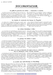
7.6 CS I/O PORT PIN DESCRIPTION
All external communication peripherals
to the CR500 through the 9-pin subminiature
type socket connector located on the front of
the Wiring Panel (Figure 7.6-1). Table 7.6-1
shows the l/O pin configuration, and gives a
brief description of the function of each pin.
r
la
5LXTAL t/U
-.\
r4
|
ooooo
\-,/
\-/ \_,/ \,/
FIGURE 7.6-1. 9-pin Female Connector
36
cRs00
TABLE 7.6-1. Pin Description
=
PIN =
O =
| =
ABR
Abbreviation for the function name.
Pin number.
Signal Out of the CR500 to a
peripheral.
Signal Into the CR500 from a
Pe{Pheral'
PIN ABR
5V
1
I/O
O
PIN
Description
ABR
r/o
SDE
o
cLl(Hs l/o
5V: Sources 5 VDC, used
to power peripherals.
Signal Ground: Provides a
power return for pin 1 (5V),
and is used as a reference
for voltage levels.
RING I
4RXDI
5
ME O
Ring: Raised by a
peripheral to put the
CR500 in the
telecommunications mode.
Receive Data: Serial
data transmitted by a
peripheral are received
on pin 4.
Modem Enable: Raised
when the CR500
determines that a modem
raised the ring line.
Synchronous Device
Enable: Used to
address Synchronous
Devices (SDs), and can
be used as an enable
line for printers.
Clocl</Handshake: Used
with the SDE and TXD
lines to address and
transfer data to SDs.
When not used as a clock,
pin 7 can be used as a
handshake line (during
printer output, high
enables, low disables).
Not used.
8
9
Description
TXD
Transmit Data: Serial
data are transmitted
from the C8500 to
peripherals on pin 9;
logic low marking (0V)
logic high spacing (5V)
standard asynchronous
ASCIl, 8 data bits, no
parity, 1 start bit, 1 stop
bit,300, 1200,9600,
76,800 baud (user
selectable
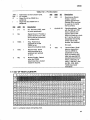
7.7 DAY OF YEAR CALENDAR
Add 1 to unshaded values during leap years'
37