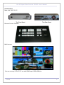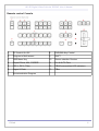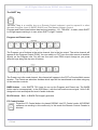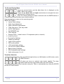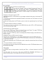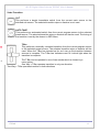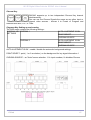
1
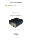
HD/SD Digital Video Switcher DSC945. User’s Manual HD/SD SDI Master Control Switcher . User's Manual DVLab 1 HD/SD Digital Video Switcher DSC945. User’s Manual Overview. Construction Inputs / Outputs Remote control Console The SHIFT key Program and Preset rows BLACK,BARS,PC Control On Screen Display Menu Transition Selection PiP and Titles LOGO 1, LOGO 2, CLOCK Transition CHROMA KEY Main Unit - Rear Panel MULTI-VIEW Multi-screen information: DSC945 Connections Remote Control Console DB9 -DB9 cable How to connect DSC945 to the PC through Ethernet (TCP / IP) EthernetSetup.exe DSCConfig.exe DSCRemote.exe Titling Program «TitleMaster» How to update the DSC945 Firmware Specification Dimensions Warranty DVLab 3 4 5 6 7 7 7 8 8 9 10 11 12 14 17 18 20 20 21 22 23 24 27 29 30 31 32 2 HD/SD Digital Video Switcher DSC945. User’s Manual Overview The DVLab DSC945 is 8 SD/HD SDI +1HDMI Master Control switcher. The DSC945 switcher provides an array of simple-to-use features: Inputs and Outputs Embedded and Analog Audio. Each audio source, including embedded and analog, can be associated with any or several video sources. Audio follows Video switching operation. Built in Frame Synchronizer for each channel; Built in Multi-screen Wipe effects Black image Source BARS with 1 kHz audio Source Two PiP Two Logos (up to 8 pre-stored including 1 Dynamic Logo) . External Titles ( with -a-channel or Luma Key). 2 Chroma Key. Luma Key 8 Still pictures instead each Input . PC or OSD menu settings. Audio Delay up to 16 Field by each Audio inputs Upgrade and Update through Ethernet 24 bit Audio Processing IP streaming ( Optional) AUX Commutator 8x2 TALLY Output Wireless TALLY Option ETHERNET Remote Control Power AS 220 or DС 9-15V ( optional) DVLab 3 HD/SD Digital Video Switcher DSC945. User’s Manual Construction Main Unit: RAC 2U 19`: The Front Panel Remote Control Console: The Rear Panel Multi-screen: You can use any LCD HD TV set with HDMI input 1920х1080 pix. DVLab 4 HD/SD Digital Video Switcher DSC945. User’s Manual Inputs / Outputs The mixer has 8 SDI input and 1HDMI Input, which may be the HD and SD - determined by the Inputs settings. SD signals Format can be 4:3 or 16:9. Switcher has separate frame synchronizer for each of Inputs. Note: The HDMI input in the regular use is working with HD or SD signals 1920x1080i, 720x576i and 720x576P. Therefore, when playing video clips from PC or other devices, this clips must be prepared accordingly. Each input can be switched to a slide . Video Inputs: 8 HD /SD SDI, 8 x BNC . 1 HDMI Audio Inputs Analog 4 mono or 2 stereo. 4XLR SDI and HDMI Embedded Audio, 1-st Stereo pair from each Input. Video outputs Out 1 and Out 2- HD SDI, Out 3 and Out4 HD/SD SDI. 4 BNC HDMI Out – Multi-screen or Program Each of SDI outputs can be Program presets as Program Logo Free Program Logo &Titles Free Preview AUX Audio Outputs Output SDI Embedded Audio One Stereo-pair (Group and Pair can be selected). Analog Audio Two Mono or One Stereo-pair (2 XLR) HDMI Out Embedded Audio. DVLab 5 HD/SD Digital Video Switcher DSC945. User’s Manual Remote control Console 1 PC Control On /Off 8 CHROMA Key Control 2 Program to Multi-screen 9 SHIFT 3 OSD Menu Key 10 Source selection Preview 4 Wipes Effects, MIX, FREEZE 11 Cut & AUTO Take 12 T-BAR end position LED indicators 13 T-Bar 5 PiP 1, PiP 2, Titles 6 Logos & Clock 7 Source selection Program DVLab 6 HD/SD Digital Video Switcher DSC945. User’s Manual The SHIFT key. The SHIFT key is a modifier key on a Remote Control keyboard, used to expand it to other alternate functions: Input 9, BARS, BLACK and Title Master software Control. Program and Preset rows buttons has two-level marking : 1/9 , 7/BLACK - it mean, when SHIFT is not light upper marking is in use, when SHIFT is light – bottom. Program and Preset rows The Program row of buttons is the active channel, this is the live output. The active channel will appear as the Program Output (PGM). You can switch or CUT from one video source to another directly on the Program row. You will see the multi view PGM output change as you press different keys along this top row of buttons. The Preset row is the cued channel, this channel will appear in the PST or Preview Multi-screen window . The Preset row selection decides which input will be transitioned next when using any of the transition controls. BARS button – color SMPTE 75% bars for use on the Program and Preset row. The BARS button can be accompanied ( In the OSD Menu ) with the built audio source signal 1 kHz 0 dB, designed to test and adjust the level of audio channels. BLACK button – Built -in BLACK Field signal generator PC Control button. Press the PC Control button for placed DSC945 into PC Control mode. All DSC945 software can working in this mode only. In this mode the Remote Control Console is blocked. DVLab 7 HD/SD Digital Video Switcher DSC945. User’s Manual On Screen Display Menu Press any arrows button and the Main Menu list is displayed on the HDMI 1 Multi-view output. Press the up, down, left, and right arrow buttons to navigate the menu options and to change values. Once the chosen setting has been confirmed with the ENTER button it is stored within the switchers non-volatile memory. Press any button to return to the operating mode. MENU SETTINGS: Inputs Video settings Audio Level adjustment Audio to Buttons Associations T-Bar One way or Two way mode AUTO TAKE speed Soft BORDER size Clock settings External Titles – mode Luma or 2 Components (with a- channel) Luma Key Level Chroma Key Settings Wipes Key settings. Logo & Clock position PIP size & position AUX commutator setting. On /Off 1kHz (0dB) to BARS. Back to factory Settings SDI Embedded audio settings. Audio mixing type (V or X) Transition Selection Six user defined wipe buttons, an A/B dissolve or MIX button, and a FREEZE button. All wipes can have an optional color border applied. The wipe border width and color are chosen within the menu system. Transitions can be performed manually using the T-Bar or automatically by using the SPEED and AUTO TAKE buttons. DVLab 8 HD/SD Digital Video Switcher DSC945. User’s Manual PiP and TITLES PIP Preset and PIP Program. There are four PIP keys. These are labeled Program and Preset. The upper PIP1 and PIP2 keys relate to activating Picture In Picture images on the Program outputs. The lower PIP1 and PIP2 keys relate to activating Picture In Picture images on the Multi-view or Preview outputs. Assigning a video source input to a PIP: Using the lower PIP1 or PIP2 buttons you can assign a selected video input to the chosen PIP video layer. 1) First press and hold down the required PIP button on the lower row. The Preset row of input sources will light. 2) While still holding down the PIP button, press to select the required input from the Preset row. 3) The input will flash to confirm it is selected. This selection will also be confirmed on the HDMI Multi-view, with a PiP1 or PiP2 label shown next to the selected input image. TITLES Preset and TITLES Program. There are two TITLES keys. These are labeled Program and Preset. The upper TITLES key relate to activating Down Stream Keying on the Program outputs. The lower TITLES key relate to activating Down Stream Keying on the Multi-view or Preview outputs. Assigning an input to a DSK channel for keying: Using the lower TITLES button you can assign a selected video input to the DSK video layer. 1. First press and hold down the required TITLTS PVW button on the lower row. The Preset row of input sources will light. 2. While still holding down the TITLES button, press to select the required input from the Preset row. 3. The input will flash to confirm it is selected. This selection will also be confirmed on the HDMI Multi-view, with a TITLES label shown next to the selected input image. Titling Mode The DSC945 has two titling methods: Luma Key and Titles + a Channel selected in the OSD menu. Luma Key mode. You can use any video sources (HD/SD SDI, CVBS,HDMI, Still Pictures ) to replace the black parts of this image with the video from another source. DVLab 9 HD/SD Digital Video Switcher DSC945. User’s Manual Titles + a-CH mode (alpha channel mode) .You can use HD/SD SDI and HDMI inputs only. This Titles is used 2 signals , therefor 2 SDI inputs is in use. Thus, if you choose to input 1 as titles signal, the input 2 is automatically assigned as achannel. If Input 2 – a-channel is Input 3 and so on. But if In 8 – a-channel is In 1. As to HDMI - the Title Master software allow to use one HDMI inputs for two signal passing through. The Title Masters software Titles can be controlled by SHIFT/ Preset row keys:Play/pause, >>, << LOGO 1, LOGO 2, CLOCK The DSC945 has the ability to store seven static logos and one dynamic logo. The logo files are transferred to the DSC945 from a Windows PC using the Ethernet connection and the supplied DSConfig software. The LOGO 1 and LOGO 2 buttons are used to display pre-selected logos on the Preset and Program outputs. When the button is active the selected logo is shown. These logos are selected from the switcher’s memory and positioned using a menu option . LOGO 2 or CLOCK The user cannot display LOGO 2 and CLOCK at the same time. Instead use LOGO 1 and CLOCK together or use LOGO 1 and LOGO 2 together. The clock time can be synchronized with a computer or set manually using a menu option. The color and font used in the clock digits can be changed using the supplied DSConfig software. DVLab 10 HD/SD Digital Video Switcher DSC945. User’s Manual Video Transition CUT This performs a simple immediate switch from the current main source to the selected sub source. The selected transition wipe or dissolve is not used. AUTO TAKE This performs an automated switch from the current program source to the selected preset source. The selected transition wipe or dissolve will also be used. The timing of the transition is set by the chosen in OSD Menu. T-Bar This performs a manually controlled transition from the current program source to the selected preset source. The selected transition wipe or dissolve will be used. When the T-Bar has traveled as far as it can go the transition between sources is complete. The T-Bar has indicators next to it which light when the transition is complete. The T-Bar can be operated in one of two modes which is chosen by a menu option: One Way = T-Bar operates transition in only one direction Two Way = T-Bar operates transition in both directions DVLab 11 HD/SD Digital Video Switcher DSC945. User’s Manual Chroma Key DSC945 supports up to two independent Chroma Key channel simultaneously . You can use the Chroma Signals the same as any other input or internal video sources : choose it to Preset or Program and switched with Auto, Cut , or T-Bar. Chgroma Key Setting up and running The OSD menu contains the following settings : CHROMA KEY CHROMA 1 SETTINGS AUTO AJUSTMENT IS ON POINT SELECT CHROMA SOURCE CHROMA 2 AUTO AJUSTMENT IS ON POINT SELECT CHROMA SOURCE AUTO AJUSTMENT IS ON“- enable / disable the automatic background settings POINT SELECT– point ( 1 or 2 see below ) on the background for key signal information.1 CHROMA SOURCE – an "Actor"source selection: 1-9= input numbers, 0= disables Chroma DVLab 12 HD/SD Digital Video Switcher DSC945. User’s Manual There is 3 buttons for Chroma control: CHR1 CHR2 CHR AUTO: CHR1 and CHR2 Buttons enable the Chroma 1(2) and used to select the source «ACTOR» and «BACKGROUND” Using the CHR1 (2) button you can assign a selected video input to the CHROMA video layer. 1. First press and hold down CHR1 (2) button . The Preset and Program rows of input sources will light. 2. While still holding down the CHR1 (2) button, press to select the required «Actor” from the Program row, and then press to select the required «Background” from the Preview row 3. The selected inputs will flash to confirm it is selected. CHROMA AUTO button CHR AUTO button - Enable / disable the automatic settings .If this mode is not switched off in the case of any foreign objects will appear in the automatically tracking area may occur distortions .. CHR AUTO button lights up when at least one of the CHR1 or 2 is in the automatic tuning . Enabling and disabling Auto mode is as follows: 1. Press and hold down the button CHR AUTO - light up CHR1 CHR2. 2. If the CHR 1 (2) blinks , it means that the automatic mode is ON. It can be switched off by pressing the blinking button . On - press again . 3. Exit the operating mode - release the CHR AUTO. DVLab 13 HD/SD Digital Video Switcher DSC945. User’s Manual Main Unit - Rear Panel 1 Inputs 1-8 HD/SD-SDI;9-HDMI 7 Grounding Terminal 2 Inputs / Outputs Analog Audio 8 AC 220V + Fuse. 3 In Sync 9 Remote Control Console (DB9F -DB9F) 10 Dip switch. ^ Work; v Update 11 TALLY (DB9M) SD4SDI Outputs 1 -4 HD/SD SDI 5 Output HDMI Multi view 6 Ethernet (RJ45) 1. HD/SD-SDI Inputs (BNC) All inputs SDI embedded audio.. 3. Outputs. 4 BNC connectors: Outputs 1-2 = HD SDI,Outputs 3-4 = HD/SD SDI ( is chosen in the menu). All outputs is embedded audio. Group and pair is chosen in the menu . Each of these SDI outputs has the option to be: 1. Program output 2. Preview output 3. Program output without logo 4. Program output without logo and DSK 5. Aux output of a selected input channel DVLab 14 HD/SD Digital Video Switcher DSC945. User’s Manual HDMI MULTIVIEW OUT HDMI outputs (1920 х 1080i x 50 Hz) which can be used to display a preset combination of inputs plus program and preset. ETHERNET RG45 Connector for Upgrade, Logos, Configuration, Time setting and Remote Control. CONSOLE DB-9M for remote Control Console. TALLY DB-9F (8 key) Analog Audio Inputs 4 Analog Audio Inputs (4 x XLR 3 pin) Analog Audio Outputs Supports two channels XLR Balanced Audio output. DVLab 15 HD/SD Digital Video Switcher DSC945. User’s Manual GND Grounding Terminal When connecting this unit to any other component, make sure that it is properly grounded by connecting this terminal to an appropriate point. When connecting, use the socket and be sure to use wire with a cross-sectional area of at least 1.0 mm. AC In 220В 50Hz+ Fuse DVLab 16 HD/SD Digital Video Switcher DSC945. User’s Manual MULTI-VIEW DSC945 Multi-view monitoring is available across one HDMI monitors (not supplied). These HDMI outputs can be used to monitor video and audio in a number of different configurations. For each set up, embedded audio level indication is also available on all inputs as well as the Preview and Program windows. This Multi-view is supplied from the HDMI connection on the rear panel. You can choose 3 windows configuration of multi-skrin In the menu: Configuration A: Preview and Program windows + 9 live inputs Configuration B: The other variant of Preview and Program windows + 9 live inputs Configuration C: Preview and Program windows + 6 live inputs DVLab 17 HD/SD Digital Video Switcher DSC945. User’s Manual Multi-screen information: 1) Name of Channels. 2) Selected inputs (Program/preset/PIP). 3) Transition Effects 4) Audio mix type (V or X). 5) Clock 6) Menu 7) Audio Level Indicators 8) LOCKED or UNLOCKED 9). PC CONTROL or CONSOLE CONTROL. Yellow mark– preset, and Red mark-Program Wipes Effects MIX Audio Transition X-type Audio Transition V- type Titles, PiP1 , PiP 2 «PC control» mode – Button PC Control is pressed (is light) and connection between the PC and the device is found. DVLab 18 HD/SD Digital Video Switcher DSC945. User’s Manual Button PC Control is not pressed ( no light) and Console Control is connected and in working condition. Note: Variable appearance of these inscriptions indicates that the control signal is absent. DVLab 19 HD/SD Digital Video Switcher DSC945. User’s Manual DSC945 Connections Multi screen is connected by standard HDMI Cable PC is connected by LAN cable (UTP RG45) Direct PC connection by Crossover. Connection via HUB by Direct. Remote Control Console is connected via DB 9 -DB9 cable To DSC945 (“keyboard”) 9pin F To Console (“keyboard”) 9 Pin F 1 N.C. N.C 1 2 3 TXD RXD TXD RXD 2 3 5 9 GND +VCC (+12V) GND +VCC (+12V) 5 9 DVLab 20 HD/SD Digital Video Switcher DSC945. User’s Manual How to connect DSC945 to the PC through Ethernet (TCP / IP) Connecting to a PC is required in the following cases: Settings – the program "DSCConfig". Uploading logos and Still pictures – the program "DSCConfig". Remote Control - the program "DSC REMOTE CONTROL" Titling – the program Title Master Required PC setting: The computer should be equipped with network adapter with installed TCP/IP. Network adapter properties: The computer IP address can be assigned statically or dynamically (DHCP). As example IP address is 192.168.1.3 (shown at the Figure below). DVLab 21 HD/SD Digital Video Switcher DSC945. User’s Manual The switcher’s IP address can be found and changed. Can be changed with the program EthernetSetup.exe, included in the DSCConfig. installation: So in the our example PC IP address is 192.168.1.3 but DSC945 IP address is 192.168.31.211 In this case the IP address of the DSC945 must be 192.168.1.XX, where XX - is not involved in any of the network number, for example 192.168.1.25 DVLab 22 HD/SD Digital Video Switcher DSC945. User’s Manual DSC945 Sofware DSCConfig.exe - Settings, Logs loading, Still Pictures Loading, Multi-screen settings. DSCConfig Program 1. Set connections-— Ethernet . 2. Set «Choose». 3. Push Find for list of IP addresses in Network 4. Choice IP number or set if number is known from our example (page 22) 192.168.1.25 Settings tab DSCConfig allows you to set the all DSC945 parameters. There are two tabs settings. First Common Settings - all settings except inputs setting The second - to set the inputs separately for each of the 9 inputs. Still pictures tab DSC945 switcher has the ability to store 9 still pictures in its frame stores. DVLab 23 HD/SD Digital Video Switcher DSC945. User’s Manual The LOAD button can used to browse for a picture stored on the computer. This picture is then loaded into the application window. The WRITE button can then be used to save the new picture into a selected frame store on the switcher. As the slide can be any image format BMP, PNG, TGA size of 1920x1080 pixels, 24 bits. For each of the Inputs one slide can store in the device memory. Logos tab The SE-2800 can store up to seven still and 1 dynamic logos in its memory. Using the logos tab you can use the LOAD button to browse for a logo stored on the computer. This logo is then loaded into the application window. The WRITE button can then be used to save the new logo into a selected logo store on the switcher. As the Logo can be any image format BMP, PNG, TGA size of 256x128 pixels, 24 bits. DVLab 24 HD/SD Digital Video Switcher DSC945. User’s Manual DSC Remote.exe It is possible to control the DSC945 with a PC using an Ethernet connection. The DSC Remote software supplied with the switcher needs to be installed on the computer first: 1. Connect an Ethernet cable between the PC and the DSC945. 2. Turn on the PC and DSC945. 3. Placed DSC945 into PC Control mode. To do this press the PC Control button on its Control Panel . 4. Launch the DSCRemote software on the PC. Remote software displays an image of the SDSC945’s keyboard as shown below The Settings (S) button is located just above the T-Bar in the display above. When clicked a new window will open: This Settings window is used to match the software to the IP address of the connected SE2800 switcher. If unknown, the switcher’s IP address may be found using the DSC Config software or found and changed by using the EthernetSetup.exe software. NOTE: It is not possible to run both the DSC Config and DSC Remote software applications at the same time. DVLab 25 HD/SD Digital Video Switcher DSC945. User’s Manual The PC used must be in the same IP network as the DSC945. So the first three octets (numbers) in the PC’s IP Address must match the first three octets of the switcher’s IP address. The fourth octet should be a different number for the PC and switcher. To reset the IP Address of the PC/laptop use the Network and Sharing Center option in Windows Control Panel. Click on Local Area Connection then Properties. Click to highlight Internet Protocol Version 4 (TCP/IPv4) then click Properties again. Then click Use the following IP address Software based Macro functions It is possible to record a Macro type play-list to the computer when using the DSCRemote software. This Macro function allows these pre-recorded keyboard actions or selections to be played back within a project where timing is important or where the same steps are repeated throughout the production. The Macro function buttons are REC, and PLAY. These buttons are located just above the T-Bar in the SE Remote display. REC & PLAY functions Left mouse click the gray REC button and it will light up red. All of your actions when using the Remote Console will now be recorded to file. The only action that will not be recorded is the T-Bar, use the CUT or AUTO TAKE buttons instead. Click the red REC button again and a save window will appear. You can now save the recorded actions as a macro text file to a chosen location on the computer. Click the gray PLAY button and a load file window will appear. You can now browse to and load a macro text file. When you load a file the recorded actions will begin to play back until the end of the file. TIME function This button is located just above the T-Bar in the DSC 945 Remote display . Mouse clicking on the TIME button will synchronize the time on the DSC945 switcher to the current time on the computer. DVLab 26 HD/SD Digital Video Switcher DSC945. User’s Manual «TitleMaster». This Software allows using the HDMI input of the DSC945 Switcher as a source of a-cannel Titles. The system is designed for video and broadcast design and includes PC with installed TitleMaster software and switcher DSC945. The system allows to display text information "scrolling" or "drum" (the number of "running lines" is unlimited) logo, including dynamic (number and size are not limited to) video playback (the size may be any) with sound , a variety of substrates and various image processing for the channel with transparency. System requirements for complex Windows XP, Windows Vista or Windows 7. The processor of at least 2.5 GHz, 1 GB of RAM . DirectX version 9.0c from June 2010 or later. Video card with two outputs ( second exit - with connector Hdmi), with support for Direct X 9 , textures up to 2048x2048. Any serial video card ATI / AMD or Nvidia with a storage capacity of 500 MB and above. You can import files: 0 BMP ( single or couple on white and on a black background). DVLab 27 HD/SD Digital Video Switcher DSC945. User’s Manual 1 TGA ( with alpha channel , if there is one) . 2 PNG ( with alpha channel , if there is one) . 3 JPG 4 GIF ( with transparency , if there is one) . For animation, you can use : 2 Animated GIF ( the time that each frame is taken from the file itself ) . 3 AVI ( with alpha channel , if it is, the time that each frame is specified framerate file). 4 TXT - text file , each line specifies the filename for the image of the next frame (which is allowed to specify the full path) , and separated by semicolons , the time frames in milliseconds . If no time is specified, the frame is taken for 20 ms. For video , you can use the formats that are played in the system via a standard Media Player. Text - text allows different fonts, sizes , pattern , color change letters and background. The transparency of the text can be changed from 0 to 100 %. The text can be fixed , the running line or a drum at a predetermined speed scrolling. In the case of mobile text after scrolling text can either stop or get stuck . By movable frames with text not limited. The program allows you to upload files to the encoding ANSI / OEM (for example: Win-1251), UNICODE and UTF-8. The file encoding is determined either automatically or manually selected. For a moving text, use the entire file CSV, for still - one current line. More information on TitleMaster software can be found in its separate description. DVLab 28 HD/SD Digital Video Switcher DSC945. User’s Manual How to update the DSC945 Firmware Customers can update the DSC945C firmware themselves if they wish or they can contact their local dealer or reseller for assistance should they prefer this method. Once started the update process should not be interrupted in any way as this could result in a non-responsive unit. To update the DSC945 firmware: 1. Switch off the DSC945 and Computer in the normal way. 2. Connect the Ethernet cable between the DSC945 rear panel and the Computer. 3. Turn on the Windows 7 Computer. 5. Double click the firmware update icon to launch the Flash Update Utility. 6. Confirm the supported devices list says DSC945 then click NEXT. 7. Select Device is connected via Ethernet then click NEXT. 8. In the next window you can POWER ON the DSC945 and it will be discovered by the Computer. 9. Select Automatically update the device to latest firmware version then click NEXT. 10. Click the Yes button to confirm you wish to perform the firmware update. 11. The update process will begin and two progress bars will be shown. The lower bar, Total Progress, will take around 15 minutes to complete. 12. Once this process is complete close the application and power cycle the DSC945. DVLab 29 HD/SD Digital Video Switcher DSC945. User’s Manual Specification Inputs Video 9 inputs : 8 HD /SD SDI, 1HDMI Inputs Audio 4 Analog Audio Balanced, 4 x XLR 3 pin Outputs Video 1x HDMI for Multi-screen 4 BNC for HD/SD-SDI outputs Outputs Audio 2 Analog Audio Balanced, 2x XLR 3 pin Other Interface 1 x RJ45 — for remote control 1xBNC for Sync In D-Sub 9 Pin Remote Console D-Sub 15 Pin x 1 Tally Operating Temperature 0°C to 40°C (32°F to 102°F) Humidity 10% to 90% (non condensing) Dimension & Weight Base Unit :Rack 2U, 440mm (W) x 96mm (H) x 400mm (D) = 3.5 Kg Control Panel : 431mm (W) x 50mm (H) x 260mm (D) = 2.44 Kg Power • Input AC 100 ~ 240V 35W DVLab 30 HD/SD Digital Video Switcher DSC945. User’s Manual Dimensions DVLab 31 HD/SD Digital Video Switcher DSC945. User’s Manual Warranty Warranty period – 24 months from the selling date The manufacturer does not take any responsibility for defects occurred at the customer’s fault or trading company’s during careless transportation, improper storage, technical service or usage, mechanical damages, violating the operation rules. The software is delivered “as is” unless mentioned otherwise. The manufacturer does not bear responsibility for any consequences of using the software. The software can be used without any limitations. Additional information on the software interfaces can be sent upon request. The manufacturer reserves a right to bring any changes to the product, software or description without notice. Please ask manufacturer for latest information and updates. Dear customers! We make improvements and/or changes in our products and we reserve the right to make changes without notice. Though every effort has been made to ensure that this document is current and accurate, more information may have become available subsequent to the production of this guide. Our products are under continual improvement, so we would like to draw your attention to the fact that the old-model devices may not be supported by the most recent version of our software. It is caused by using in our equipment advanced technical solutions and new electronic components. We are pleased to receive at [email protected] comments and remarks regarding our products and software. At the same address we are ready to provide further information about the products application and updated software. DVLab 32 HD/SD Digital Video Switcher DSC945. User’s Manual Apps Environment Requirement Environment Temperature 5~40℃(sustainable),0~45℃(short time), installing air-conditioning is recommended Power Requiring device power, air-conditioning power and lighting power are independent to each other. Device power requires AC power 220V 50Hz. Please carefully check before running. Machine Hall Floor Electric Isolation, Dust Free, Ground anti-static material. Grounding Requirement Good grounding is the basis of reliability and stability of devices. Good grounding are the most important guarantee of lightning arresting and interference rejection. Coaxial cable’s outer conductor and isolation layer should keep proper electric conducting with the metal housing of device. Grounding conductor must adopt copper conductor in order to reduce high frequency impedance, and the grounding wire must be as thick and short as possible. It is prohibited to use any other device as part of grounding electric circuit The area of the conduction between grounding wire and device’s frame should be no less than 25mm2. DVLab 33