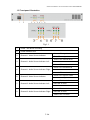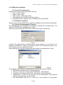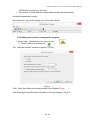
1
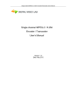
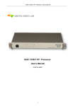
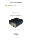
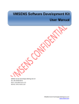
MPEG-2 /H.264 HD Encoder/Transcoder User’s Manual Dual channel MPEG-2 / H.264 Encoder / Transcoder User’s Manual Version: 1.0 Date:May 2013 DVLab NDS3211P MPEG-4 AVC/H.264 HD Encoder User’s Manual DIRECTORY 1. PRODUCT OUTLINE 1.1 OUTLINE 1.2 THE ENCODER KEY FEATURES: 1.3 THE TRANSCODER KEY FEATURES 1.4 SPECIFICATION 1.5 FRONT PANEL ILLUSTRATION 1.6 REAR PANEL ILLUSTRATION 2. HOW TO WORK WITH ENCODER/TRANSCODER MPEG 4/MPEG 2 2.1 ENCODER/TRANSCODER MAIN PART 2.2 ENCODER MODE SETTINGS 2.3TRANCODER MODE SETTINGS 3. OPERATION 3.1 DVBSETTING PROGRAM 3.2. DVBTOOLKIT INSTALLATION 3.2.1 SERVER PC REQUIREMENTS: 3. 2.2 SOFTWARE INSTALLATION 3.2.3 STARTING THE MANAGEMENT PROGRAM 3.2.4 ADDING DEVICE TO THE CONFIGURATION PROGRAM 3.3 ENCODER SETTINGS 3.4 TRANSCODER MODE 3.5. OUTPUTS. 3.5.1 RECOMMENDATIONS. 3.5.2 IP OUTPUTS SETTINGS 3.5.4 ASI OUTPUTS SETTINGS 4.WARRANTY 5.APPS 5.1 ENVIRONMENT REQUIREMENT 5.2 GROUNDING REQUIREMENT 5.3. HOW TO CONNECT NEW DEVICE TO THE SYSTEM THROUGH ETHERNET (TCP / IP) 5.4 HOW TO ADD A NEW DEVICE TO THE SYSTEM. 3 3 4 5 6 7 8 9 9 9 9 10 10 11 11 11 11 12 14 16 20 20 22 24 25 25 25 25 26 30 NDS3211P MPEG-4 AVC/H.264 HD Encoder User’s Manual 1. ProductOutline 1.1 Outline The device can work in two modes “Encoder” or “Transcoder”. The necessary mode is selected by program witching. The dual channel Encoder is intended for real time encoding of CVBS or SD/HD SDI signals into MPEG-2 SD or H.264 SD/HD format. The dual channel Transcoder is intended for real-time transcoding/ transrating of two SD/HD program from two Transport Streams (TS) from MPEG-2 to H.264 format or vice versa. Each channel generates up to two TS. One of the two TS provides high resolution (1920х1080 or less) for high quality broadcasting, the other TS provides low resolution (320х240 or less) for broadcasting to mobile devices or Internet. The Encoder/Transcoder enables multiplexing of the four TS onto any of the two ASI outputs or any of the four IP addresses. Built-in multiplexer: each output can be configured to carry either a Single Program Transport Stream (SPTS), or a Multi Program Transport Stream (MPTS). 3 / 34 NDS3211P MPEG-4 AVC/H.264 HD Encoder User’s Manual 1.2 The Encoderkey features: • Two SDI / two CVBS inputs. • Full HD 1080i support. • Analog XLR and Serial Digital embedded audio inputs. • Provides internally generated PSI. • Selectable MPEG-2 SD or H.264 SD/HD real-time video encoding. • Simultaneous output of 2xTS (ASI) with UDP/IP or RTP/IP transport stream. • CBR or VBR outputs. • User selectable resolution and bit rate. • MPEG-1 Layer audio encoding. • Built-in multiplexer can output 2 individual or one multiplexed ASI and IP streams. • Control and monitoring via LAN (Ethernet). 4 / 34 NDS3211P MPEG-4 AVC/H.264 HD Encoder User’s Manual 1.3 The Transcoderkey features: • Transcoding of an SD/HD program: from MPEG-2 (SD/HD) to MPEG-2 (SD) format; from MPEG-2 (SD/HD) to H.264 (SD/HD) format ; from H.264 (SD/HD) to MPEG-2 (SD) format; • Digital to digital decode and re-encode with minimum loss in video quality; • Supports multi-bitrate transcoding • Up to 1080i HD output; • Audio is passed trough; • PID filtering; • Built-in multiplexer allows to generate output TS with transcoded programs and/or original programs which are being applied at the input; • PSI generation; • Supports OTA, EPG, DVCrypt CAS 3000/10000/100000 subscribers; • Input interface: DVB ASI (2); • Output interface: DVB-ASI (2) and IP(1) ; 5 / 34 NDS3211P MPEG-4 AVC/H.264 HD Encoder User’s Manual 1.4 Specification Video Input Analog Input:) two Composite, BNC (75Ω Level: 1 Vp-p Digital Input:) two SDI, BNC (75Ω Level: 800mVp-p Aspect Ratio: 4:3, 16:9 Audio Input Analog Input: 2 Stereo (4 channels, XLR) Freq. Range: 20Hz ~ 20KHz Impedance: 600 Ω/ 20KΩ Digital Input: Embedded SDI Sampling Rate: 48 KHz Video Encoder Encoding: MPEG-2 HP@HL, MP@HL, MP@ML MPEG-4 H.264 HP@L4, MP@L3 Encoding Rate: 0,5~15 Mbps Chroma Format: 4:2:0 Bit Rate Mode: CBR,VBR Audio Encoder Encoding: MPEG-1 Layer II 64 - 320 Kbps Sampling Rate: 48KHz TS Output Transport Stream: ASI 2 port Connector: BNC(75Ω) TS Bit Rate: 0,5~14 Mbps Packet Format: 188 Byte IP TS Output and Ethernet control Ethernet type: 10/100 Base-T (RJ-45) Format: UDP/IP, RTP/IP IP Address Format: Multicast, Unicast TS Bit rate: 0,5~60 Mbps TS Packet format: 188 Byte General Power: ~220V+\-20% Power Consumption: Max 10W Size: 19``, 1U 480*45*180 (mm) Weight: 3 Kg 6 / 34 NDS3211P MPEG-4 AVC/H.264 HD Encoder User’s Manual 1.5 Frontpanelillustration Fig.1.1 1 Power the device is working 2 Power Indicator LED 3 Channel 1 Video Source Indicator Green LED: signal is exists Red LED: no signal Green LED: Nominal level 4 Channel 1 Audio Source Indicator. Left Red LED: Hi level Yellow LED: Low level Green LED: Nominal level 5 Channel 1 Audio Source Indicator. Right Red LED: Hi level Yellow LED: Low level 6 Channel 2 Video Source Indicator Green LED: signal is exists Red LED: no signal Green LED: Nominal level 7 Channel 2 Audio Source Indicator. Left Red LED: Hi level Yellow LED: Low level Green LED: Nominal level 8 Channel 2 Audio Source Indicator. Right Red LED: Hi level Yellow LED: Low level 7 / 34 NDS3211P MPEG-4 AVC/H.264 HD Encoder User’s Manual Rearpanelillustration Fig.1.2 1. Channel 1 CVBS input interface Digital audio input interface: AES/EBU, XLR 2. Channel 2 CVBS input interface 3. Channel 1 HD/SD-SDI or ASI input interface 4. Channel 2 HD/SD-SDI or ASI input interface 5, 6 Two same ASI output interfaces 7. ETHERNET / IP 8. Channel 1 Analog audio Left input interface 9. Channel 1 Analog audio Right input interface 10. Channel 2 Analog audio Left input interface 11. Channel 2 Analog audio Right input interface 12. FAN 13. Ground pole 14. Power and FUSE 8 / 34 NDS3211P MPEG-4 AVC/H.264 HD Encoder User’s Manual 2. How to Work with encoder/TranscoderMPEG 4/MPEG 2 1 Encoder/Transcodermain part Preparing relevant environment for installation (See 5.1 Page 25). Grounding Requirement (See 5.2 Page 25). Connecting Power Cord (14. Fig.1.2). Connecting ASI OUT to the device with ASI Input (5 or 6. Fig.1.2) Connecting communication port to PC via Ethernet for the Encoder Settings.(RJ45 7.Fig.1.2). Switch on Power (1.Fig.1.1). Set Encoder/Transcoder IP Address (using EthernetSetup.exe utilite). (See 5.3 Page 24). Start on PC DVBToolkit program. Add the Encoder/Transcoder to System. The wizard will help you connect it to the system (See 5.4 Page 30). Start DVB_Setting program from the DVBToolkit`s client.(See 2.1 Page 9.) 2 EncoderMode Settings Start DVB_Setting program from the DVB Toolkit`s client3.2. ( See DVBToolkit installation Page 11) Preset Encoder parameters you need..(See 3.3 Encoder settings . Page 14) Load the new parameters to the Encoder: Click “Parameters Settings” button. After recording, the Encoder is ready for use. 3TrancoderMode Settings Select Transcoder Mode ( 2.3 Trancoder Settings, Page 9) PresetTranscoder parameters you need. (See 3.4 Transcoder Settings. Page 16) Load the new parameters to the Transcoder: Click “Parameters Settings” button. After recording, the Transcoder is ready for use. 4 OutputSettings IP Outputs Settings ( See 3.5.2 IP Outputs Settings . Page 22) ASI Outputs Settings ( See 3.5.4 ASI Outputs Settings . Page 24) 9 / 34 NDS3211P MPEG-4 AVC/H.264 HD Encoder User’s Manual 3. Operation 3.1 DVBSetting program Control of the parameters encoder is using a utility DVB_Setting, which is part of the program DVBToolkit, which allows you to adjust the speed of the output flow rate of the audio stream, and change the mode of operation of the encoder, with a constant bit rate (CBR), or a variable (VBR). The output resolution and format of the input signal can also be selected programmatically. 10 / 34 NDS3211P MPEG-4 AVC/H.264 HD Encoder User’s Manual 3.2. DVBToolkitinstallation 3.2.1 ServerPC requirements: please check that following requirements are met: CPU: 1 GHz or faster; RAM: 1 GB or more; HDD: at least 1 GB of free space; LAN adapter and/or USB for modules interface; Operating System: Windows XP, or Windows server 2003/2008. 3. 2.2 Software installation Simply run the included DVBToolkit_Install.exe installation file and follow the prompts. 3.2.3 Starting the ManagementProgram The Management (или Configuration?) Program is started from the Start menu. / All Programs / DVBToolkit / Management Program When you start the program will require to choose the type of connection: Fig.3.1 Locally, if the program Server installed on the same computer, or to a server, if it is installed on another PC. Then it is necessary to enter the IP address and port of the PC on which you have installed the server. After selecting the connection window will open system of administration "Login": Fig.3.2 The program uses a system of administration which is structured as follows: DVBToolkit contains several functional modules. There is a main user of the program DVBToolkit – Administrator. All rights to use these functions (on / off) belong to the administrator. Administrator is enters to the program as an “administrator” with personal password and appoints the other users. The administrator also can on / off some of the functions of the program 11 / 34 NDS3211P MPEG-4 AVC/H.264 HD Encoder User’s Manual DVBToolkit, necessary for the user. The number of users and their rights determined by the administrator. All default passwords is empty. By clicking the Login button brings you to the main window: Fig.3.3. 3.2.4 Adding device to the configuration program 1. Select View – Modules from the menu or icon. 2. Click on Add new module icon The “Add new module” window is appear ( Fig.3.4): Fig.3.4. Click “Next” and follow the wizard prompts (See Chapter.5 Page ___). After finishing the new Encoder will added to the main window ( Fig.3.5): 12 / 34 NDS3211P MPEG-4 AVC/H.264 HD Encoder User’s Manual Fig.3.5. After Encoder/Transcoder is added, double-click on green field to change the settings (Fig.3.6): Fig. 3.6 3.3 EncoderMode settings The encoder has an output re-multiplexer, which allows to set the desired output flow rate of the encoder. Output flow rate should not be less than the maximum flow rate of both channels plus 200 kbits / sec. 13 / 34 NDS3211P MPEG-4 AVC/H.264 HD Encoder User’s Manual Setting the encoder is to choose the required parameters for each of the devices. Fig.3.6. Moreover, the selected settings can be saved in the device for each channel separately or for both channels simultaneously. This is done so that if the encoder in the broadcast mode you can change the settings on the same channel without disturbing the broadcast that comes from a different channel. So you can select the " selected " or " all channels " radio button. Mode " Test Tone " allows you to turn on the sound output of the encoder and the color bar generator. If any of these parameters have been chosen correctly, then when you click "Install the setup. " warning appears Fig.3.7. Fig.3.7 If you select "Yes", then set parameters will be recorded, if you select "No", then the wrong selections are highlighted in red, and when you hover the mouse on them will appear showing a hint of how to change the setting to set it right. Fig.3.8. 14 / 34 NDS3211P MPEG-4 AVC/H.264 HD Encoder User’s Manual Fig.3.8. The button "Recommended" sets the operating parameters that can be recorded by pressing the "Save settings" (Fig.3.8). The button "Restore factory settings" is used to return the encoder The "Restore factory settings" to return the encoder to the working condition in the event of incorrect settings. in a case of incorrect settings parameters. You can change the PID, and the ID number of the elementary stream. 15 / 34 NDS3211P MPEG-4 AVC/H.264 HD Encoder User’s Manual 3.4 TranscoderMode Settings 1. Select "Transcoder" Fig.. 3.9. Fig.3.9 2. Click OK and wait until the device goes from the "Encoder" to "Transcoder" that can be seen in the status bar DVBToolkit Fig..3.10. Fig. 3.10. 3. Scan inputs ASI streams and take programs for transcoding: click icon In the main window toolbar (Fig..3.11) Fig..3.11 The Multiplexer Window is appears (Fig. 3.12): 16 / 34 NDS3211P MPEG-4 AVC/H.264 HD Encoder User’s Manual Fig. 3.12 Click “Start scan” After the scan is complete the message appears (Fig. 3.13): Fig. 3.13 After the scan is complete: Select the Input program for output stream formation and drag them by mouse to the right window ( Fig. 3.14). In the right window highlight programms for transcoding. 17 / 34 NDS3211P MPEG-4 AVC/H.264 HD Encoder User’s Manual Enable the "Transcoding". Fig.3.1 4. If necessary, you can Click “Chang e the Transcoding parameters” and Settings window will appear (Fig.3.1 5): Fig.3.15. Once the options are selected click "OK” - come back previous window (Fig. 3.14) Nex Step: Measure the velocity of the selected stream and compare it with a valid value. If it is valid, сlick "Save settings in the device" and move on to the next window . 18 / 34 NDS3211P MPEG-4 AVC/H.264 HD Encoder User’s Manual Fig.3.16. Select the "Save service information to the stream." Wait until the end of recording and producing an output stream that is completed. The output stream will be present transcoding programs. 19 / 34 NDS3211P MPEG-4 AVC/H.264 HD Encoder User’s Manual 3.5. Outputs. The Encoder/Transcoder has 4 IP output. IP output may be used for monitoring or IP broadcast It is also possible multiplex mode, in that case main IP stream has 4 IP stream Device`s outputs. Each IP output of the encoder may have its own IP address: 1. channel 1 2. Channel 1 + 3. Channel 2 4. Channel 2 + The channel with "+" is the channel with the lower resolution. Supported protocols UDP, RTP. The Encoder has two equal ASI outputs, each of which may operate in one of the following modes: 1. Channel 1 2. Channel 1 + 3. Channel 2 4. Channel 2 + 3.5.1 Recommendations. The maximum rate of traffic flow can not be more than 15 Mbit / s. Mode CBR. The difference in speed between the transport stream and the video stream is recommended to choose TS-(TV + Ta), at least 400 kbit / s. Where TS- traffic flow. TV- video stream. TA- audio stream. Mode VBR. The minimum bitrate (min) 0-0,75 the average bit rate (average) Maximum bit rate (max) 1.2-2 medium (average) bit rates Bitrate transport (transport stream) not less than 400 kbit / s bit rate greater than the maximum bitrate + audio. It should be borne in mind that the recommended resolution mode for encoder Mode HD: 1920x1080 50i 1440x1080 50i 960x1080 50i 720x1080 50i 1920x1080 60/59, 94i 1440x1080 60/59, 94i 960x1080 60/59, 94i 720x1080 60/59, 94i 20 / 34 NDS3211P MPEG-4 AVC/H.264 HD Encoder User’s Manual Mode SD: 720x576 50i 704x576 50i 720x480 60/59, 94i 704x480 60/59, 94i 21 / 34 NDS3211P MPEG-4 AVC/H.264 HD Encoder User’s Manual 3.5.2 IP Outputs Settings Click icon «IP» on the toolbar (Fig..3.11) IP output configuration window appears Fig.3.17. Fig.3. 17. The encoder has the opportunity to work with two IP address es sent in one IP strea m. Each encoder channel may have its own IP address. There are several operation modes for each IP channel: 1. Output is disabled. 2. The output is commutated to channel 1. 3. The output is commutated to channel 2. 4. The output delivers two multiplexed channels The second channel works in the same mode. If two channels work in the "Multiplex mode", stuffing should be switched off (disabled), or one channel should be disconnected, while the second may work in the "multiplex" mode both with the enabled and disabled stuffing. In the "channel1" and "channel2" modes stuffings are disabled. It is necessary to choose IP address and port that the stream will be broadcast to, as well as the protocol (RTP, UDP, RTP +) for each of the channels. After selecting the required parameters you should click "start" and close the window. It is possible to check (monitor) work of IP inputs using VLC player. Select Media / Network and enter the necessary parameters. An example is given on Figure below. 22 / 34 NDS3211P MPEG-4 AVC/H.264 HD Encoder User’s Manual 23 / 34 NDS3211P MPEG-4 AVC/H.264 HD Encoder User’s Manual 3.5.4 ASI Outputs Settings Fig.3.18. 24 / 34 NDS3211P MPEG-4 AVC/H.264 HD Encoder User’s Manual 4.Warranty Warranty period – 24 months from the selling date The manufacturer does not take any responsibility for defects occurred at the customer’s fault or trading company’s during careless transportation, improper storage, technical service or usage, mechanical damages, violating the operation rules. The software is delivered “as is” unless mentioned otherwise. The manufacturer does not bear responsibility for any consequences of using the software. The software can be used without any limitations. Additional information on the software interfaces can be sent upon request. The manufacturer reserves a right to bring any changes to the product, software or description without notice. Please ask manufacturer for latest information and updates. Dearcustomers! We make improvements and/or changes in our products and we reserve the right to make changes without notice. Though every effort has been made to ensure that this document is current and accurate, more information may have become available subsequent to the production of this guide. Our products are under continual improvement, so we would like to draw your attention to the fact that the old-model devices may not be supported by the most recent version of our software. It is caused by using in our equipment advanced technical solutions and new electronic components. We are pleased to receive at [email protected] comments and remarks regarding our products and software. At the same address we are ready to provide further information about the products application and updated software. 25 / 34 NDS3211P MPEG-4 AVC/H.264 HD Encoder User’s Manual 5.Apps 5.1 EnvironmentRequirement Environment Temperature 5~40 (sustainable) 0~45 (short time) installing air-conditioning is recommended Power Requiring device power, air-conditioning power and lighting power are independent to each other. Device power requires AC power 220V 50Hz. Please carefully check before running. Machine Hall Floor Electric Isolation, Dust Free, Ground anti-static material. 5.2 Grounding Requirement Good grounding is the basis of reliability and stability of devices. Good grounding are the most important guarantee of lightning arresting and interference rejection. Coaxial cable’s outer conductor and isolation layer should keep proper electric conducting with the metal housing of device. Grounding conductor must adopt copper conductor in order to reduce high frequency impedance, and the grounding wire must be as thick and short as possible. It is prohibited to use any other device as part of grounding electric circuit The area of the conduction between grounding wire and device’s frame should be no less than 25mm2. 26 / 34 NDS3211P MPEG-4 AVC/H.264 HD Encoder User’s Manual 5.3. How to connectnewDevice tothe System through Ethernet(TCP / IP) Servercomputersetting The server computer should be equipped with network adapter with installed TCP/IP. Network adapter properties: The computer IP address can be assigned statically or dynamically (DHCP). As example IP address is 192.168.1.3 (shown at the Figure below). 27 / 34 NDS3211P MPEG-4 AVC/H.264 HD Encoder User’s Manual Connection scheme is shown below: The server is connected to a standard Ethernet hub/switch. The Device are connected to the Ethernet hub/switch, too. There can be other computers in this local network. If the server is connected to a local network containing other PC, it is recommended to install the second network adapter in the server in order to guarantee fail-safe and secure connection. In this case the connection scheme should be the following: First network adapter and Device are attached to a hub. The second network adapter is attached to other hub connected to other PC. Select “Module interface/Ethernet” option in Server settings: If the server contains special network adapter for connection to Device, it is necessary to select “Bind to network adapter” option and assign its IP address. 28 / 34 NDS3211P MPEG-4 AVC/H.264 HD Encoder User’s Manual 29 / 34 NDS3211P MPEG-4 AVC/H.264 HD Encoder User’s Manual 5.4 How to add a new Device to the system. To add a new Device to the system connect it to the hub by a cable and switch it on. Press button Add new module Select connection type Ethernet New Device connected to the system will be searched, their MAC and IP addresses will be listed. Search can be repeated by pressing Refresh button. If there are a few Devices, it is difficult to determine the Device among others. In this case you can select the Device in the list and press Blink button. The selected Device will flash red LED (built in Ethernet connector) three times. Next step is entering IP address of selected Device. 30 / 34 NDS3211P MPEG-4 AVC/H.264 HD Encoder User’s Manual The server will set the IP addres Select any free IP address in the range of this local network (for example, we use addresses from 92.168.1.100 to 192.168.1.200) and enter it. Network mask and Default gateway should be set only if the Device will work in other subnetwors for the new Device and add it to the system. The IP address and MAC will be shown in Devices window in Control Software. It will be impossible to change the Device IP address hereafter. To change the Device IP address it is necessary to delete the Device from the system and add it again. After adding the Device it should be set. Double click on the Device number and it will appear Convertersetting window, Notes If the distance between the Server and Devices is rather long and there are routers, and automatic search doesn't work - in this case it is necessary to do the following: Connect the new Device to the local network or to the Server directly and set the IP address as described above. Not waiting that the system will find and add the Converter, interrupt the adding procedure. Connect the new Converter to remote network. Run adding procedure and select the 31 / 34 NDS3211P MPEG-4 AVC/H.264 HD Encoder User’s Manual option “The module is not listed here. Enter IP address of the module directly” Enter IP address of the Device (Module). The server will try to communicate with the Device and add it to the system: Attention! All Devices are delivered set to the IP address 192.168.0.254 or 192.168.0.253, 32 / 34 NDS3211P MPEG-4 AVC/H.264 HD Encoder User’s Manual network mask 255.255.255.0. The Devices should have different IP addresses when you add them to the system. The delivery set includes EthernetSetup.exe utility which makes it possible to change Device IP address and network mask. The utility doesn't require installation. Before changing the IP address connect the Device to Ethernet hub/switch, connect to it also a PC having installed network board (network board IP address should be in the Device IP address range. For example, the Device IP address is 192.168.0.254, then network board IP address can be in 192.168.0.1.. 192.168.0.254 range, network mask 255.255.255.0). Then run EthernetSetup.exe, the program will find the Device. Select the device and press Setup button The Network parameters window will appear, where you can change the Device IP address and network mask. The procedure of assigning IP address should be performed for all Devices before adding them to the system. Pressing Ping button 33 / 34 NDS3211P MPEG-4 AVC/H.264 HD Encoder User’s Manual you can check connection between the PC and the Device. If you press Blink button, the selected Device will flash red LED (built in Ethernet connector) three times. Attention! It is not recommended to change the Device IP address after the Device has been already added to the system as it will cause connection failure. To re-establish connection it is necessary to repeat procedure of adding the Device to the system again. 34 / 34