1
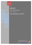
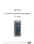
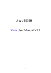
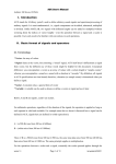
8ASI / DVB-T RF Processor User’s Manual
8ASI / DVB-T RF Processor
User's Manual
CAS ID 4AEC
1
8ASI / DVB-T RF Processor User’s Manual
1. Product Overview
3
1.1. Outline
3
1.2. Main features
3
1.3. Specification
5
1.4. Front panel illustration
6
1.5. Rear Panel illustration
7
1.6. Connections
8
2. Operation
10
2.1. Common information
10
2.1.1. Environment Requirement
10
2.1.2. Grounding Requirement
10
2.2. System Installation
11
2.3. How to add a new Processor to the System
11
2.4. Server PC network parameters settings
12
2.4.1. Server PC requirements
12
2.4.2. Server computer setting
12
3. DVCrypt operation
14
3.1. Software installation
14
3.2. Starting the Control Program
14
4. New Processor Installation
17
5. Processor settings
23
5.1. RF Output settings
23
5.2. Output Stream forming
24
5.3. IP Outputs Settings
25
6. Warranty
27
2
8ASI / DVB-T RF Processor User’s Manual
1. Product Overview
1.1 Outline
The 8ASI DVB-T 1RF/2RF Processor is a multinational device intended for multichannel DVB-T
broadcasting. It provides TS re-multiplexing, scrambling, modulating and Up-converting.
Key advantages:
•
The processor remultiplexes up to 8 input Transport Streams(TS) and forms a group spectrum
of up to 2 TS in the DVB-T format transmitted at two different frequencies.
•
Standard SD/ HD DVB-T receivers and DVB-T TV-sets can be used as subscriber receivers.
•
IP output can be used to transport one of the packages via IP network or monitor one of the
packages chosen from output or input stream at your PC.
Оne Processor allows you to organize DVB-T broadcasting of 10-15 programs , as well as a system
for monitoring of channels on your PC. The Processor can replace the two remultiplexers, two scramblers, two DVB-T Modulators and two UP-converters.
1.2 Main features
•
Quick replacement of the device in the system without stream rescan.
•
Software update/upgrade.
•
DVCrypt CAS support.
•
EPG, OTA, LCN support, Network Search.
•
Adjustable level of the output RF signal.
•
Quick replacement of the device in the system without stream rescan
•
MPEG-2, MPEG-4/AVC, HD / SD and 3D support.
•
Automatic and manual PID insertion;
•
Connection to PC: Ethernet (100 MBit /s), RJ45.
•
IP output: Supported protocols RTP, UDP.
•
IP output can be used to transport one of the packages via IP network.
•
Visual monitoring the input and output streams with the free program DVCrypt Ts Monitor via
IP
•
IP allows you to record the output ASI stream to the PC for further analysis.
•
One or two carriers can be set within 36-850 MHz range, subcarrier frequency can be set with
in 48 MHz.
3
8ASI / DVB-T RF Processor User’s Manual
Frequency adjustment of output signal
2RF
Examples of spectrum settings for each TS within 48MHz bandwidth
4
8ASI / DVB-T RF Processor User’s Manual
1.3 Specification
INPUT INTERFACE
ASI Inputs
8 DVB ASI streams, 8 BNC Connectors
ASI OUTPUTS
DVB-ASI Outputs
2 DVB ASI, 2 port, 2 BNC Connectors
RF Output
Connector
F-type
Frequency range:
36-850 MHz (adjustable)
Output RF signal level
00 dB/uV, adjustment -10dB/uV;
MODULATION
Modulation type
QPSK/QAM16/QAM64;
DELTA-
1/4, 1/8, 1/16, 1/32;
FEC-
1/2, 2/3, 3/4, 5/6, 7/8;
IFFT-
2K
IP TS Output and Ethernet control
Ethernet type:
10/100 Base-T (RJ-45)
Format:
UDP/IP, RTP/IP
IP Address Format:
Multicast, Unicast
TS Bit rate:
0,5~60 Mbps
TS Packet format:
188 Byte
General
Power:
~220V+\-20%
Power Consumption:
Max 18W
Size:
19``, 1U 480*45*180 (mm)
Weight:
3 Kg
5
8ASI / DVB-T RF Processor User’s Manual
1.4 Front panel illustration
1
Power on/off switch
2
Power Status Indicator ( LED)
3
Input ASI Signal Source Status Indicator
(1-8).
LED Light: signal is available
1, 2 OVERFLOW indicator for each of
two formed packages
LED Light : Attention! Overflow!
4,5
No light: no signal
No Light: no Overflow
ASI INPUTS (1-8). Indication of the ASI stream at the relevant input.
If the ASI signal cable is connected to the Processor, but the LED does not light or blinks, it may indicate either of absence of ASI signal, or poor contact or ASI Stream parameters are not correct.
OVERFLOW (1,2) : Each of the two built-in multiplexers has an indicator showing the maximum allowable stream is exceeded.
Note. As the input streams typically have a variable bit rate, so at the Processor settings time the
formed steam may be correct, but during broadcast the input streams may increase and cause
spillage of the subscriber images. To avoid this problem on the important channels, it is possible to assign one channel as the one that may be subject to restrictions.
6
8ASI / DVB-T RF Processor User’s Manual
1.5 Rear Panel illustration
1.
ASI inputs (1-8)
2.
ASI outputs (1,2)
3.
RF Out: Radio Frequency output
4.
ETHERNET / IP
5
Cooling FAN
6
Ground pole
7
Fused Power Inlet
8
Fuse
7
8ASI / DVB-T RF Processor User’s Manual
1.6 Connections
Fused Power Inlet: AC In 220V 50Hz + Fuse
GND
Grounding Terminal
When you connect the Processor to any other device, make sure that it is properly
grounded by connecting this terminal to an appropriate point. When connecting, use the socket and be sure
to use a wire with a cross-sectional area of at least 1.0 mm.
ASI Inputs
ASI
INPUTS
2
4
1
3
6
5
8
7
Input signals must comply with the EN 50083-9:1998 standard.
ASI Outputs
ASI
OUT PUTS
2
1
Two modes are possible:”One spectrum ” and “Two spectrums”.
In the “One spectrum” mode each of the two outputs has the same ASI stream.
In the “Two spectrums” mode one of 4 variants can be set:
1. The first spectrum ASI to the ASI Out 1.
The second spectrum ASI to the ASI Out 2.
2. The first spectrum ASI to the ASI Out 2.
The second spectrum ASI to the ASI Out 1.
3. The first spectrum ASI to the ASI Out 1 and ASI Out2
4. The second spectrum ASI to the ASI Out 1 and ASI Out2
8
8ASI / DVB-T RF Processor User’s Manual
RF Output.
RF OUT
F Connector. Frequency range 36-850 MHz (adjustable)
IP Out
ET H ER N ET
The Processor receives eight streams and forms two streams. Any of two outputs and
each of the eight input streams may be directed to the IP output (not simultaneously). See
figures below:
.
9
8ASI / DVB-T RF Processor User’s Manual
2. Operation
2.1 Common information
Processor should be connected to the PC for settings, control, Update and Upgrade (the Processor’s rear
panel RJ45 connector).
The Processors have built-in system time synchronization. The control computer is synchronized from the
source time signal and in turn synchronizes the Processor. The processor provides a timing signal which
synchronizes a receiver. In case of loss of synchronization signal whole system will work, but the wrong
time will be indicated. DVCrypt program will write this event in the server log.
2.1.1 Environment Requirement
•
Operating Temperature 5~40,0~45℃(short time), air-conditioning is recommended.
•
Device power, air-conditioning power and lighting power are independent of each other.
Device power requires AC power 220V 50Hz. Please carefully check before use.
•
Machine Hall Floor Electric Isolation, Dust Free, Ground anti-static material.
2.1.2 Grounding Requirement
•
Good grounding is the basis of reliability and stability of devices. Good grounding is the most
important guarantee against electric discharge and interference.
•
Coaxial cable’s outer conductor and isolation layer must ensure proper electric conductivity
with the metal housing of device.
•
Grounding conductor must adopt copper conductor in order to reduce high frequency
impedance, and the grounding wire must be as thick and short as possible.
•
It is prohibited to use any other device as part of grounding of electric circuit.
•
The area of the conduction between grounding wire and device’s frame should be no less than
25mm2.
10
8ASI / DVB-T RF Processor User’s Manual
2.2 System Installation
It is necessary to provide:
1. Operating System: Windows XP or Windows server 2003/2008.
2. DVCrypt program (or DVBToolkit in case when encrypting is not necessary).
3. HUB/switch for local area computer networks ( for simultaneous connection of all the Processors to
a single computer).
RJ45 connector cable for connection to the HUB:
1
2
3
4
5
6
7
8
RJ45
white / orange
orange
white / green
blue
white / blue
green
white / brown
brown
RJ45
white / orange
orange
white / green
blue
white / blue
green
white / brown
brown
1
2
3
4
5
6
7
8
Connect one by one all processors to the DVCrypt server and register them in the system. The system will
automatically assign a number to the new Processor and will monitor the numbers of all processor in the
system.
2.3 How to add a new Processor to the System
Attention! When you connect the Processor to the PC, power should be switched off and all
equipment should be grounded.
1. Connect the Processor by means of a HUB or Switch to the PC.
2. Set the Server PC network parameters.
3. Install and launch DVCrypt program
4. Click the “Processors” icon and the “Processors” window will appear.
5. Click the + icon and follow the wizard's instructions to install the Processor.
6. If everything is done correctly and the Processor is found, it will appear in the " Processors "
window.
7. Double click the left button of the mouse on the number of the processor and the “Settings”
window will appear, where it is necessary to point the name of the channel fed to the Processor inputs and the frequency at which the Processor operates.
8. Repeat steps 1-6 for all Processors.
11
8ASI / DVB-T RF Processor User’s Manual
2.4 Server PC network parameters settings.
2.4.1 Server PC requirements:
Please check that the following requirements are met:
•
CPU: 1 GHz or faster;
•
RAM: 1 GB or more;
•
HDD: at least 1 GB of free space;
•
LAN adapter and/or USB for modules interface;
•
Operating System: Windows XP, or Windows server 2003/2008.
2.4.2 Server computer setting
The server computer must be equipped with network adapter with installed TCP/IP.
Network adapter properties:
The computer IP address can be assigned statically or dynamically (DHCP).
As example IP address is 192.168.1.3 (shown at the Figure below).
12
8ASI / DVB-T RF Processor User’s Manual
Connection scheme is shown below:
The server is connected to a standard Ethernet hub/switch. The Device is connected to the Ethernet
hub/switch. There can be other computers in this local network. If the server is connected to a local
network containing other PC, it is recommended to install the second network adapter in the server in
order to guarantee fail-safe and secure connection. In this case the connection scheme should be the
following:
First network adapter and Device are attached to a hub. The second network adapter is attached to
other hub connected to other PC.
13
8ASI / DVB-T RF Processor User’s Manual
3. DVCrypt operation
3.1. Software installation
Launch DVCrypt_Install.exe installation file and follow the prompts.
3.2 Starting the Control Program
The Control Program can be launched from the Start menu. / All Programs / DVCrypt / Control Program. When you launch the program, it will ask you to choose the connection type.
Select “This computer” if the program Server is installed on the same computer, or “Remote server” if
it has been installed on another PC. Then it is necessary to enter the IP address and port of the PC on
which you have installed the server.
After the connection to the Server, system of administration "Login" window will appear:
The program uses a system of administration which is structured as follows:
•
Administrator is a main user of the DVBCrypt program.
• Administrator enters the program as an “Administrator” with personal password and appoints
the other users.
•
The Administrator also can on / off some functions of the DVBCrypt program.
•
The number of users and their rights determined by the administrator.
All default passwords are empty.
14
8ASI / DVB-T RF Processor User’s Manual
DVCrypt program contains two main functional modules. DVCrypt Client and DVCrypt Server.
Clicking the Login button brings you to the DVCrypt Client main window:
The DVCrypt Server can be launched from the taskbar.
To open the DVCrypt Server log, click mouse left button on the Server Icon and the Server Log Window will appear.
To open the DVCrypt Server Settings, click mouse right button on the Server Icon and select Settings.
In the Server settings it is necessary to enable communication with the Processor - Ethernet:
If the Server has one network adapter for communication with the Processor, it is recommended to enable the option “The network interface only” and set it's IP address:
15
8ASI / DVB-T RF Processor User’s Manual
16
8ASI / DVB-T RF Processor User’s Manual
4. New Processor Installation
1) Connect a new Processor to a HUB (RJ45 - RJ45 cable) and the HUB to the Server PC.
2) Turn on the Processor power.
3) In the DVCRypt Client Window click left button on icon
the DVCRypt Client -Modules window will opened.
4) Click on the icon “Add new Module” and the “Add new module” window will appear
5) Select connection type for the new module - Ethernet:
Click “Next” and follow the wizard prompts
NOTE!
New Device connected to the system will be searched, their MAC and IP addresses will be listed.
Search can be repeated by pressing Refresh button. If there are a few Devices, it is difficult to determine the Device among others. In this case you can select the Device in the list and press Blink
button. The selected Device will flash red LED (built in Ethernet connector) three times.
Select the Processor (Module) and click next.
17
8ASI / DVB-T RF Processor User’s Manual
6) Next step is entering IP address of the selected Device.
Select any free IP address in the range of this local network (for example, we use addresses from
92.168.1.100 to 192.168.1.200) and enter it. Network mask and Default gateway should be set only if
the Device will work in other subnetworks.
The server will set the IP address for the new processor and add it to the system:
18
8ASI / DVB-T RF Processor User’s Manual
The IP address and MAC will be shown in Devices window in Control Software. It will be impossible to
change the Device IP address hereafter. To change the Device IP address it is necessary to delete
the Device from the system and add it again.
After adding the Device it should be set. Double click on the Device number and it will appear Converter setting window.
Note. If the distance between the Server and Devices is rather long and there are routers, and automatic search doesn't work - in this case it is necessary to do the following:
19
8ASI / DVB-T RF Processor User’s Manual
Connect the new Device to the local network or to the Server directly and set the IP address as described above. Do not wait till the system will find and add the Converter, interrupt the adding procedure.
Connect the new Converter to remote network. Launch adding procedure and select the option “The
module is not listed here. Enter IP address of the module directly”
Enter IP address of the Processor (Module).
The server will try to communicate with the Device and add it to the system:
20
8ASI / DVB-T RF Processor User’s Manual
Attention!
All Devices are delivered set to the IP address 192.168.0.254 or 192.168.0.253, network mask
255.255.255.0.
The Devices should have different IP addresses when you add them to the system. The delivery set
includes EthernetSetup.exe utility which makes it possible to change Device IP address and network
mask. The utility doesn't require installation. Before changing the IP address connect the Device to
Ethernet hub/switch, connect to it also a PC having installed network board (network board IP address
should be in the Device IP address range. For example, the Device IP address is 192.168.0.254, then
network board IP address can be in 192.168.0.1.. 192.168.0.254 range, network mask
255.255.255.0). Then launch EthernetSetup.exe, the program will find the Device.
Select the device and press Setup button.The Network parameters window will appear, where you
can change the Device IP address and network mask.
21
8ASI / DVB-T RF Processor User’s Manual
The procedure of assigning IP address should be performed for all Devices before adding them to the
system. Pressing Ping button you can check connection between the PC and the Device. If you press
Blink button, the selected Device will flash red LED (built in Ethernet connector) three times.
Attention!
It is not recommended to change the Device IP address after the Device has been already added to
the system as it will cause connection failure. To re-establish connection it is necessary to repeat procedure of adding the Device to the system again.
After finishing the procedure, the new Processor will be added to the main window.
22
8ASI / DVB-T RF Processor User’s Manual
5. Processor settings
5.1 RF Output settings
1. Power on Processor.
2. Launch DVCrypt Program.
3. Add the Processor to System (Page__)
4. Click on icon “12” on the Instruments Panel.
The settings window will appear:
The Processor Settings will be saved when you click the "Set your settings". It can be done both after
the all settings are done or after each setting.
Modulation type is selected by “QAM” radio buttons. The modulation type by default is QAM 64.
Frequency is set by “MHz”slider or you can enter the Frequency in the windows.
First spectrum frequency is priority. Second frequency depends on it's value, so first you need to set
the frequency of the first spectrum and then the frequency of the rest one.
Output power level is set by “Output Power” slider or you can enter it in the window ( 0-9db range).
Click on the “ Set selected settings” button to save them to the device.
23
8ASI / DVB-T RF Processor User’s Manual
5.2 Output Stream forming
The Output Stream is formed using the DVB_Service utility (the part of DVCrypt)
24
8ASI / DVB-T RF Processor User’s Manual
5.3 IP Outputs Settings
Click on «IP» icon on the tool-bar and IP output configuration window will appear.
You need to set:
1. Protocol (RTP, UDP, RTP +)
2. Port
3. IP address the stream will be broadcast to.
4. IP Stream source. The Source can be an input or output stream, scrambled or not scrambled,
with stuffings or without stuffings.
Select the required parameters, click on "start" button and close the window.
It is possible to monitor work of IP using VLC player.
25
8ASI / DVB-T RF Processor User’s Manual
Select Media / Network and enter the necessary parameters. An example is given on the Figure
below.
26
8ASI / DVB-T RF Processor User’s Manual
6. Warranty
Warranty period – 24 months from the selling date
The manufacturer does not take any responsibility for defects occurred at the customer’s fault or
trading company’s during careless transportation, improper storage, technical service or usage,
mechanical damages, violating the operation rules.
The software is delivered “as is” unless mentioned otherwise. The manufacturer does not bear responsibility for any consequences of using the software. The software can be used without any
limitations. Additional information on the software interfaces can be sent upon request.
The manufacturer reserves a right to bring any changes to the product, software or description
without notice. Please ask manufacturer for latest information and updates.
Dear customers!
We make improvements and/or changes in our products and we reserve the right to make
changes without notice. Though every effort has been made to ensure that this document is current and accurate, more information may have become available subsequent to the production of
this guide.
Our products are under continual improvement, so we would like to draw your attention to the fact
that the old-model devices may not be supported by the most recent version of our software. It is
caused by using in our equipment advanced technical solutions and new electronic components.
We are pleased to receive at [email protected] comments and remarks regarding our products
and software. At the same address we are ready to provide further information about the products
application and updated software.
27