1
Part No. 209321-A
August 2000
4401 Great America Parkway
Santa Clara, CA 95054
Getting Started with the
Business Policy Switch 2000
Management Software
2
Copyright © 2000 Nortel Networks
All rights reserved. August 2000.
The information in this document is subject to change without notice. The statements, configurations, technical
data, and recommendations in this document are believed to be accurate and reliable, but are presented without
express or implied warranty. Users must take full responsibility for their applications of any products specified in
this document. The information in this document is proprietary to Nortel Networks NA Inc.
The software described in this document is furnished under a license agreement and may be used only in
accordance with the terms of that license. The software license agreement is included in this document.
Trademarks
NORTEL NETWORKS is a trademark of Nortel Networks.
Microsoft, MS, MS-DOS, Windows, and Windows NT are registered trademarks of Microsoft Corporation.
All other trademarks and registered trademarks are the property of their respective owners.
Restricted rights legend
Use, duplication, or disclosure by the United States Government is subject to restrictions as set forth in
subparagraph (c)(1)(ii) of the Rights in Technical Data and Computer Software clause at DFARS 252.227-7013.
Notwithstanding any other license agreement that may pertain to, or accompany the delivery of, this computer
software, the rights of the United States Government regarding its use, reproduction, and disclosure are as set forth
in the Commercial Computer Software-Restricted Rights clause at FAR 52.227-19.
Statement of conditions
In the interest of improving internal design, operational function, and/or reliability, Nortel Networks NA Inc.
reserves the right to make changes to the products described in this document without notice.
Nortel Networks NA Inc. does not assume any liability that may occur due to the use or application of the
product(s) or circuit layout(s) described herein.
Portions of the code in this software product may be Copyright © 1988, Regents of the University of California. All
rights reserved. Redistribution and use in source and binary forms of such portions are permitted, provided that the
above copyright notice and this paragraph are duplicated in all such forms and that any documentation, advertising
materials, and other materials related to such distribution and use acknowledge that such portions of the software
were developed by the University of California, Berkeley. The name of the University may not be used to endorse
or promote products derived from such portions of the software without specific prior written permission.
SUCH PORTIONS OF THE SOFTWARE ARE PROVIDED “AS IS” AND WITHOUT ANY EXPRESS OR
IMPLIED WARRANTIES, INCLUDING, WITHOUT LIMITATION, THE IMPLIED WARRANTIES OF
MERCHANTABILITY AND FITNESS FOR A PARTICULAR PURPOSE.
In addition, the program and information contained herein are licensed only pursuant to a license agreement that
contains restrictions on use and disclosure (that may incorporate by reference certain limitations and notices
imposed by third parties).
209321-A
3
Nortel Networks NA Inc. software license agreement
NOTICE: Please carefully read this license agreement before copying or using the accompanying software or
installing the hardware unit with pre-enabled software (each of which is referred to as “Software” in this
Agreement). BY COPYING OR USING THE SOFTWARE, YOU ACCEPT ALL OF THE TERMS AND
CONDITIONS OF THIS LICENSE AGREEMENT. THE TERMS EXPRESSED IN THIS AGREEMENT ARE
THE ONLY TERMS UNDER WHICH NORTEL NETWORKS WILL PERMIT YOU TO USE THE
SOFTWARE. If you do not accept these terms and conditions, return the product, unused and in the original
shipping container, within 30 days of purchase to obtain a credit for the full purchase price.
1. License grant. Nortel Networks NA Inc. (“Nortel Networks”) grants the end user of the Software (“Licensee”) a
personal, nonexclusive, nontransferable license: a) to use the Software either on a single computer or, if applicable,
on a single authorized device identified by host ID, for which it was originally acquired; b) to copy the Software
solely for backup purposes in support of authorized use of the Software; and c) to use and copy the associated user
manual solely in support of authorized use of the Software by Licensee. This license applies to the Software only
and does not extend to Nortel Networks Agent software or other Nortel Networks software products. Nortel
Networks Agent software or other Nortel Networks software products are licensed for use under the terms of the
applicable Nortel Networks NA Inc. Software License Agreement that accompanies such software and upon
payment by the end user of the applicable license fees for such software.
2. Restrictions on use; reservation of rights. The Software and user manuals are protected under copyright laws.
Nortel Networks and/or its licensors retain all title and ownership in both the Software and user manuals, including
any revisions made by Nortel Networks or its licensors. The copyright notice must be reproduced and included with
any copy of any portion of the Software or user manuals. Licensee may not modify, translate, decompile,
disassemble, use for any competitive analysis, reverse engineer, distribute, or create derivative works from the
Software or user manuals or any copy, in whole or in part. Except as expressly provided in this Agreement,
Licensee may not copy or transfer the Software or user manuals, in whole or in part. The Software and user manuals
embody Nortel Networks’ and its licensors’ confidential and proprietary intellectual property. Licensee shall not
sublicense, assign, or otherwise disclose to any third party the Software, or any information about the operation,
design, performance, or implementation of the Software and user manuals that is confidential to Nortel Networks
and its licensors; however, Licensee may grant permission to its consultants, subcontractors, and agents to use the
Software at Licensee’s facility, provided they have agreed to use the Software only in accordance with the terms of
this license.
3. Limited warranty. Nortel Networks warrants each item of Software, as delivered by Nortel Networks and
properly installed and operated on Nortel Networks hardware or other equipment it is originally licensed for, to
function substantially as described in its accompanying user manual during its warranty period, which begins on the
date Software is first shipped to Licensee. If any item of Software fails to so function during its warranty period, as
the sole remedy Nortel Networks will at its discretion provide a suitable fix, patch, or workaround for the problem
that may be included in a future Software release. Nortel Networks further warrants to Licensee that the media on
which the Software is provided will be free from defects in materials and workmanship under normal use for a
period of 90 days from the date Software is first shipped to Licensee. Nortel Networks will replace defective media
at no charge if it is returned to Nortel Networks during the warranty period along with proof of the date of shipment.
This warranty does not apply if the media has been damaged as a result of accident, misuse, or abuse. The Licensee
assumes all responsibility for selection of the Software to achieve Licensee’s intended results and for the
installation, use, and results obtained from the Software. Nortel Networks does not warrant a) that the functions
contained in the software will meet the Licensee’s requirements, b) that the Software will operate in the hardware or
software combinations that the Licensee may select, c) that the operation of the Software will be uninterrupted or
error free, or d) that all defects in the operation of the Software will be corrected. Nortel Networks is not obligated
to remedy any Software defect that cannot be reproduced with the latest Software release. These warranties do not
apply to the Software if it has been (i) altered, except by Nortel Networks or in accordance with its instructions; (ii)
used in conjunction with another vendor’s product, resulting in the defect; or (iii) damaged by improper
environment, abuse, misuse, accident, or negligence. THE FOREGOING WARRANTIES AND LIMITATIONS
ARE EXCLUSIVE REMEDIES AND ARE IN LIEU OF ALL OTHER WARRANTIES EXPRESS OR IMPLIED,
Getting Started with the Business Policy Switch 2000 Management Software
4
INCLUDING WITHOUT LIMITATION ANY WARRANTY OF MERCHANTABILITY OR FITNESS FOR A
PARTICULAR PURPOSE. Licensee is responsible for the security of its own data and information and for
maintaining adequate procedures apart from the Software to reconstruct lost or altered files, data, or programs.
4. Limitation of liability. IN NO EVENT WILL NORTEL NETWORKS OR ITS LICENSORS BE LIABLE FOR
ANY COST OF SUBSTITUTE PROCUREMENT; SPECIAL, INDIRECT, INCIDENTAL, OR
CONSEQUENTIAL DAMAGES; OR ANY DAMAGES RESULTING FROM INACCURATE OR LOST DATA
OR LOSS OF USE OR PROFITS ARISING OUT OF OR IN CONNECTION WITH THE PERFORMANCE OF
THE SOFTWARE, EVEN IF NORTEL NETWORKS HAS BEEN ADVISED OF THE POSSIBILITY OF SUCH
DAMAGES. IN NO EVENT SHALL THE LIABILITY OF NORTEL NETWORKS RELATING TO THE
SOFTWARE OR THIS AGREEMENT EXCEED THE PRICE PAID TO NORTEL NETWORKS FOR THE
SOFTWARE LICENSE.
5. Government licensees. This provision applies to all Software and documentation acquired directly or indirectly
by or on behalf of the United States Government. The Software and documentation are commercial products,
licensed on the open market at market prices, and were developed entirely at private expense and without the use of
any U.S. Government funds. The license to the U.S. Government is granted only with restricted rights, and use,
duplication, or disclosure by the U.S. Government is subject to the restrictions set forth in subparagraph (c)(1) of
the Commercial Computer Software––Restricted Rights clause of FAR 52.227-19 and the limitations set out in this
license for civilian agencies, and subparagraph (c)(1)(ii) of the Rights in Technical Data and Computer Software
clause of DFARS 252.227-7013, for agencies of the Department of Defense or their successors, whichever is
applicable.
6. Use of software in the European Community. This provision applies to all Software acquired for use within the
European Community. If Licensee uses the Software within a country in the European Community, the Software
Directive enacted by the Council of European Communities Directive dated 14 May, 1991, will apply to the
examination of the Software to facilitate interoperability. Licensee agrees to notify Nortel Networks of any such
intended examination of the Software and may procure support and assistance from Nortel Networks.
7. Term and termination. This license is effective until terminated; however, all of the restrictions with respect to
Nortel Networks’ copyright in the Software and user manuals will cease being effective at the date of expiration of
the Nortel Networks copyright; those restrictions relating to use and disclosure of Nortel Networks’ confidential
information shall continue in effect. Licensee may terminate this license at any time. The license will automatically
terminate if Licensee fails to comply with any of the terms and conditions of the license. Upon termination for any
reason, Licensee will immediately destroy or return to Nortel Networks the Software, user manuals, and all copies.
Nortel Networks is not liable to Licensee for damages in any form solely by reason of the termination of this
license.
8. Export and re-export. Licensee agrees not to export, directly or indirectly, the Software or related technical data
or information without first obtaining any required export licenses or other governmental approvals. Without
limiting the foregoing, Licensee, on behalf of itself and its subsidiaries and affiliates, agrees that it will not, without
first obtaining all export licenses and approvals required by the U.S. Government: (i) export, re-export, transfer, or
divert any such Software or technical data, or any direct product thereof, to any country to which such exports or
re-exports are restricted or embargoed under United States export control laws and regulations, or to any national or
resident of such restricted or embargoed countries; or (ii) provide the Software or related technical data or
information to any military end user or for any military end use, including the design, development, or production
of any chemical, nuclear, or biological weapons.
209321-A
5
9. General. If any provision of this Agreement is held to be invalid or unenforceable by a court of competent
jurisdiction, the remainder of the provisions of this Agreement shall remain in full force and effect. This Agreement
will be governed by the laws of the state of California.
Should you have any questions concerning this Agreement, contact Nortel Networks, 4401 Great America
Parkway, P.O. Box 58185, Santa Clara, California 95054-8185.
LICENSEE ACKNOWLEDGES THAT LICENSEE HAS READ THIS AGREEMENT, UNDERSTANDS IT,
AND AGREES TO BE BOUND BY ITS TERMS AND CONDITIONS. LICENSEE FURTHER AGREES THAT
THIS AGREEMENT IS THE ENTIRE AND EXCLUSIVE AGREEMENT BETWEEN NORTEL NETWORKS
AND LICENSEE, WHICH SUPERSEDES ALL PRIOR ORAL AND WRITTEN AGREEMENTS AND
COMMUNICATIONS BETWEEN THE PARTIES PERTAINING TO THE SUBJECT MATTER OF THIS
AGREEMENT. NO DIFFERENT OR ADDITIONAL TERMS WILL BE ENFORCEABLE AGAINST NORTEL
NETWORKS UNLESS NORTEL NETWORKS GIVES ITS EXPRESS WRITTEN CONSENT, INCLUDING AN
EXPRESS WAIVER OF THE TERMS OF THIS AGREEMENT.
Getting Started with the Business Policy Switch 2000 Management Software
6
209321-A
7
Contents
Preface . . . . . . . . . . . . . . . . . . . . . . . . . . . . . . . . . . . . . . . . . . . . . . . . . . . . . . 13
Before you begin . . . . . . . . . . . . . . . . . . . . . . . . . . . . . . . . . . . . . . . . . . . . . . . . . . . . . 13
Text conventions . . . . . . . . . . . . . . . . . . . . . . . . . . . . . . . . . . . . . . . . . . . . . . . . . . . . . . 14
Related publications . . . . . . . . . . . . . . . . . . . . . . . . . . . . . . . . . . . . . . . . . . . . . . . . . . . 15
How to get help . . . . . . . . . . . . . . . . . . . . . . . . . . . . . . . . . . . . . . . . . . . . . . . . . . . . . . 16
Chapter 1
Management basics . . . . . . . . . . . . . . . . . . . . . . . . . . . . . . . . . . . . . . . . . . . . 17
Management tools . . . . . . . . . . . . . . . . . . . . . . . . . . . . . . . . . . . . . . . . . . . . . . . . . . . . 17
Device Manager . . . . . . . . . . . . . . . . . . . . . . . . . . . . . . . . . . . . . . . . . . . . . . . . . . . 17
Web management interface . . . . . . . . . . . . . . . . . . . . . . . . . . . . . . . . . . . . . . . . . . 18
Setting the switch IP parameters . . . . . . . . . . . . . . . . . . . . . . . . . . . . . . . . . . . . . . . . . 18
Access levels and passwords . . . . . . . . . . . . . . . . . . . . . . . . . . . . . . . . . . . . . . . . . . . 20
Chapter 2
Installing Device Manager software . . . . . . . . . . . . . . . . . . . . . . . . . . . . . . . 21
Accessing the Nortel Networks Web site . . . . . . . . . . . . . . . . . . . . . . . . . . . . . . . . . . . 21
Windows installation . . . . . . . . . . . . . . . . . . . . . . . . . . . . . . . . . . . . . . . . . . . . . . . . . . . 21
UNIX installation . . . . . . . . . . . . . . . . . . . . . . . . . . . . . . . . . . . . . . . . . . . . . . . . . . . . . . 22
Installing the software in a Solaris environment . . . . . . . . . . . . . . . . . . . . . . . . . . 23
Installing the software in an HP-UX environment . . . . . . . . . . . . . . . . . . . . . . . . . 25
Installing the software in an IBM AIX environment . . . . . . . . . . . . . . . . . . . . . . . . 26
Chapter 3
Device Manager basics . . . . . . . . . . . . . . . . . . . . . . . . . . . . . . . . . . . . . . . . . 29
Starting Device Manager . . . . . . . . . . . . . . . . . . . . . . . . . . . . . . . . . . . . . . . . . . . . . . . 29
Setting the Device Manager properties . . . . . . . . . . . . . . . . . . . . . . . . . . . . . . . . . . . . 30
Opening a device . . . . . . . . . . . . . . . . . . . . . . . . . . . . . . . . . . . . . . . . . . . . . . . . . . . . . 32
Getting Started with the Business Policy Switch 2000 Management Software
8 Contents
Device Manager window . . . . . . . . . . . . . . . . . . . . . . . . . . . . . . . . . . . . . . . . . . . . . . . 34
Menu bar . . . . . . . . . . . . . . . . . . . . . . . . . . . . . . . . . . . . . . . . . . . . . . . . . . . . . . . . 35
Toolbar . . . . . . . . . . . . . . . . . . . . . . . . . . . . . . . . . . . . . . . . . . . . . . . . . . . . . . . . . . 36
Device view . . . . . . . . . . . . . . . . . . . . . . . . . . . . . . . . . . . . . . . . . . . . . . . . . . . . . . 36
Selecting objects . . . . . . . . . . . . . . . . . . . . . . . . . . . . . . . . . . . . . . . . . . . . . . . 37
Selecting a single object . . . . . . . . . . . . . . . . . . . . . . . . . . . . . . . . . . . . . . . . . 37
Selecting multiple objects . . . . . . . . . . . . . . . . . . . . . . . . . . . . . . . . . . . . . . . . 38
Viewing information about an MDA . . . . . . . . . . . . . . . . . . . . . . . . . . . . . . . . . 38
LEDs and ports . . . . . . . . . . . . . . . . . . . . . . . . . . . . . . . . . . . . . . . . . . . . . . . . 39
Shortcut menus . . . . . . . . . . . . . . . . . . . . . . . . . . . . . . . . . . . . . . . . . . . . . . . . . . . 40
Status bar . . . . . . . . . . . . . . . . . . . . . . . . . . . . . . . . . . . . . . . . . . . . . . . . . . . . . . . 42
Using the buttons in Device Manager dialog boxes . . . . . . . . . . . . . . . . . . . . . . . . 42
Editing objects . . . . . . . . . . . . . . . . . . . . . . . . . . . . . . . . . . . . . . . . . . . . . . . . . . . . . . . 43
Working with statistics and graphs . . . . . . . . . . . . . . . . . . . . . . . . . . . . . . . . . . . . . . . . 43
Types of statistics . . . . . . . . . . . . . . . . . . . . . . . . . . . . . . . . . . . . . . . . . . . . . . . . . 44
Types of graphs . . . . . . . . . . . . . . . . . . . . . . . . . . . . . . . . . . . . . . . . . . . . . . . . . . . 44
Statistics for single and multiple objects . . . . . . . . . . . . . . . . . . . . . . . . . . . . . . . . 47
Viewing statistics as graphs . . . . . . . . . . . . . . . . . . . . . . . . . . . . . . . . . . . . . . . . . . 49
Telneting to a switch . . . . . . . . . . . . . . . . . . . . . . . . . . . . . . . . . . . . . . . . . . . . . . . . . . . 51
Trap log . . . . . . . . . . . . . . . . . . . . . . . . . . . . . . . . . . . . . . . . . . . . . . . . . . . . . . . . . . . . 51
Online Help . . . . . . . . . . . . . . . . . . . . . . . . . . . . . . . . . . . . . . . . . . . . . . . . . . . . . . . . . 52
Chapter 4
Web management interface basics . . . . . . . . . . . . . . . . . . . . . . . . . . . . . . . 53
Requirements . . . . . . . . . . . . . . . . . . . . . . . . . . . . . . . . . . . . . . . . . . . . . . . . . . . . . . . . 53
Accessing the Web interface . . . . . . . . . . . . . . . . . . . . . . . . . . . . . . . . . . . . . . . . . . . . 54
Web page layout . . . . . . . . . . . . . . . . . . . . . . . . . . . . . . . . . . . . . . . . . . . . . . . . . . . . . 56
Menu . . . . . . . . . . . . . . . . . . . . . . . . . . . . . . . . . . . . . . . . . . . . . . . . . . . . . . . . . . . 57
Content area . . . . . . . . . . . . . . . . . . . . . . . . . . . . . . . . . . . . . . . . . . . . . . . . . . . . . 59
Icons . . . . . . . . . . . . . . . . . . . . . . . . . . . . . . . . . . . . . . . . . . . . . . . . . . . . . . . . . . . 59
Setting up security . . . . . . . . . . . . . . . . . . . . . . . . . . . . . . . . . . . . . . . . . . . . . . . . . . . . 60
Setting console, Telnet, and Web passwords . . . . . . . . . . . . . . . . . . . . . . . . . . . . 61
Setting remote dial-in access security . . . . . . . . . . . . . . . . . . . . . . . . . . . . . . . . . . 62
Index . . . . . . . . . . . . . . . . . . . . . . . . . . . . . . . . . . . . . . . . . . . . . . . . . . . . . . . . 63
209321-A
9
Figures
Figure 1
Main menu . . . . . . . . . . . . . . . . . . . . . . . . . . . . . . . . . . . . . . . . . . . . . . . . 19
Figure 2
IP Configuration/Setup menu . . . . . . . . . . . . . . . . . . . . . . . . . . . . . . . . . . 19
Figure 3
Device Manager window . . . . . . . . . . . . . . . . . . . . . . . . . . . . . . . . . . . . . . 30
Figure 4
Properties dialog box . . . . . . . . . . . . . . . . . . . . . . . . . . . . . . . . . . . . . . . . 31
Figure 5
Open Device dialog box . . . . . . . . . . . . . . . . . . . . . . . . . . . . . . . . . . . . . . 33
Figure 6
Device view . . . . . . . . . . . . . . . . . . . . . . . . . . . . . . . . . . . . . . . . . . . . . . . . 34
Figure 7
Parts of the Device Manager window . . . . . . . . . . . . . . . . . . . . . . . . . . . . 35
Figure 8
Objects in the device view . . . . . . . . . . . . . . . . . . . . . . . . . . . . . . . . . . . . 37
Figure 9
MDA dialog box . . . . . . . . . . . . . . . . . . . . . . . . . . . . . . . . . . . . . . . . . . . . 39
Figure 10
Port color legend . . . . . . . . . . . . . . . . . . . . . . . . . . . . . . . . . . . . . . . . . . . . 40
Figure 11
Switch unit shortcut menu . . . . . . . . . . . . . . . . . . . . . . . . . . . . . . . . . . . . 40
Figure 12
Port shortcut menu . . . . . . . . . . . . . . . . . . . . . . . . . . . . . . . . . . . . . . . . . . 41
Figure 13
MDA shortcut menu . . . . . . . . . . . . . . . . . . . . . . . . . . . . . . . . . . . . . . . . . 41
Figure 14
Line graph . . . . . . . . . . . . . . . . . . . . . . . . . . . . . . . . . . . . . . . . . . . . . . . . . 45
Figure 15
Area graph . . . . . . . . . . . . . . . . . . . . . . . . . . . . . . . . . . . . . . . . . . . . . . . . 45
Figure 16
Bar graph . . . . . . . . . . . . . . . . . . . . . . . . . . . . . . . . . . . . . . . . . . . . . . . . . 46
Figure 17
Pie graph . . . . . . . . . . . . . . . . . . . . . . . . . . . . . . . . . . . . . . . . . . . . . . . . . 46
Figure 18
Interface statistics for a single port . . . . . . . . . . . . . . . . . . . . . . . . . . . . . . 47
Figure 19
Interface statistics for multiple ports . . . . . . . . . . . . . . . . . . . . . . . . . . . . . 48
Figure 20
Statistics dialog box for a port . . . . . . . . . . . . . . . . . . . . . . . . . . . . . . . . . 49
Figure 21
System Information home page . . . . . . . . . . . . . . . . . . . . . . . . . . . . . . . . 55
Figure 22
Login page . . . . . . . . . . . . . . . . . . . . . . . . . . . . . . . . . . . . . . . . . . . . . . . . 55
Figure 23
Parts of the Web management page . . . . . . . . . . . . . . . . . . . . . . . . . . . . 57
Figure 24
Menu . . . . . . . . . . . . . . . . . . . . . . . . . . . . . . . . . . . . . . . . . . . . . . . . . . . . . 57
Figure 25
Console password page . . . . . . . . . . . . . . . . . . . . . . . . . . . . . . . . . . . . . . 61
Figure 26
Radius management page . . . . . . . . . . . . . . . . . . . . . . . . . . . . . . . . . . . . 62
Getting Started with the Business Policy Switch 2000 Management Software
10 Figures
209321-A
11
Tables
Table 1
Properties dialog box items . . . . . . . . . . . . . . . . . . . . . . . . . . . . . . . . . . . 31
Table 2
SNMP community string default values . . . . . . . . . . . . . . . . . . . . . . . . . . 32
Table 3
Open Device dialog box items . . . . . . . . . . . . . . . . . . . . . . . . . . . . . . . . . 33
Table 4
Menu bar commands . . . . . . . . . . . . . . . . . . . . . . . . . . . . . . . . . . . . . . . . 35
Table 5
Toolbar buttons . . . . . . . . . . . . . . . . . . . . . . . . . . . . . . . . . . . . . . . . . . . . . 36
Table 6
Port color codes . . . . . . . . . . . . . . . . . . . . . . . . . . . . . . . . . . . . . . . . . . . . 39
Table 7
Switch unit shortcut menu commands . . . . . . . . . . . . . . . . . . . . . . . . . . . 40
Table 8
Port shortcut menu commands . . . . . . . . . . . . . . . . . . . . . . . . . . . . . . . . . 41
Table 9
Device Manager buttons . . . . . . . . . . . . . . . . . . . . . . . . . . . . . . . . . . . . . . 42
Table 10
Types of statistics . . . . . . . . . . . . . . . . . . . . . . . . . . . . . . . . . . . . . . . . . . . 44
Table 11
Graph dialog box buttons . . . . . . . . . . . . . . . . . . . . . . . . . . . . . . . . . . . . . 50
Table 12
Help file locations . . . . . . . . . . . . . . . . . . . . . . . . . . . . . . . . . . . . . . . . . . . 52
Table 13
User levels in the Web management interface . . . . . . . . . . . . . . . . . . . . . 56
Table 14
Menu headings and options . . . . . . . . . . . . . . . . . . . . . . . . . . . . . . . . . . . 58
Table 15
Page icons . . . . . . . . . . . . . . . . . . . . . . . . . . . . . . . . . . . . . . . . . . . . . . . . 59
Getting Started with the Business Policy Switch 2000 Management Software
12 Tables
209321-A
13
Preface
Business Policy Switch 2000 management software provides the means to
configure and monitor the operation of your Business Policy Switches.
Management software includes the console interface resident in each Business
Policy Switch; Java-based Device Manager software, which you install on a
management station in the network; and a Web-based management interface
accessible through a Web browser.
This guide provides instructions for installing the Device Manager software and
summarizes procedures for using Device Manager and the Web interface. For
information about using the console interface, refer to Using the Business Policy
Switch 2000.
This guide includes the following information:
•
•
•
•
•
A summary of management options for the switch
Instructions to install Device Manager software
A summary of navigation procedures for Device Manager and initial setup
procedures using Device Manager
An overview of the Web management interface
Common startup problems and how to troubleshoot them
Before you begin
This guide is intended for network administrators with the following background:
•
•
•
•
Basic knowledge of networks, Ethernet bridging, and IP and IPX routing
Familiarity with networking concepts and terminology
Basic knowledge of network topologies
Experience with windowing systems, graphical user interfaces (GUIs), or
Web browsers
Getting Started with the Business Policy Switch 2000 Management Software
14 Preface
Text conventions
This guide uses the following text conventions:
angle brackets (< >)
Indicate that you choose the text to enter based on the
description inside the brackets. Do not type the
brackets when entering the command.
Example: If the command syntax is
ping <ip_address>, you enter
ping 192.32.10.12
bold Courier text
Indicates command names and options and text that
you need to enter.
Example: Enter # chmod 755 ./install_dmvm.
italic text
Indicates new terms, book titles, and variables in
command syntax descriptions. Where a variable is two
or more words, the words are connected by an
underscore.
Example: If the command syntax is
install_dmvm <filename>
<target_directory>, target_directory is one
variable and you substitute one value for it.
209321-A
plain Courier
text
Indicates command syntax and system output, for
example, prompts and system messages.
Example: % JDM
separator ( > )
Shows menu paths.
Example: Edit > File System identifies the File System
option on the Edit menu.
Preface 15
Related publications
For more information about using the Business Policy Switch, refer to the
following publications:
•
Using the Business Policy Switch 2000 (part number 208700-A)
Describes how to install and use the Business Policy Switch 2000; includes
instructions to use the console interface to configure the switch.
•
Business Policy Switch 2000 Installation Instructions (part number
209319-A)
Provides installation instructions for the switch in English and five other
languages.
•
Installing Media Dependent Adapters (MDAs) (part number 302403-D)
Provides installation instructions for media dependent adapters in the
Business Policy Switch; includes descriptions of the available MDAs.
•
Reference for the Business Policy Switch 2000 Management Software
Operations (part number 209322-A)
Describes how to use Device Manager software to manage the switch.
•
Installation and Reference for the 100 Watt DC-DC Converter Module (part
number 209132-A)
Describes how to install and connect the BayStack DC-DC Converter.
•
Installing the BayStack 400-ST1 Cascade Module (part number 304433-B)
Describes how to install cascade modules in the switch and connect up to
eight such switches into a stack configuration.
•
Using Web-Based Management for the Business Policy Switch 2000 (part
number 209570-A)
Describes how to use the Web-based management interface to configure and
monitor switch operations.
Getting Started with the Business Policy Switch 2000 Management Software
16 Preface
You can print selected technical manuals and release notes free, directly from the
Internet. Go to the support.baynetworks.com/library/tpubs/ URL. Find the product
for which you need documentation. Then locate the specific category and model
or version for your hardware or software product. Use Adobe Acrobat Reader to
open the manuals and release notes, search for the sections you need, and print
them on most standard printers. Go to Adobe Systems at www.adobe.com to
download a free copy of Acrobat Reader.
You can purchase selected documentation sets, CDs, and technical publications
though the Internet at the www1.fatbrain.com/documentation/nortel/ URL.
How to get help
If you purchased a service contract for your Nortel Networks product from a
distributor or authorized reseller, contact the technical support staff for that
distributor or reseller for assistance.
If you purchased a Nortel Networks service program, contact one of the following
Nortel Networks Technical Solutions Centers:
Technical Solutions Center
Telephone
EMEA
(33) (4) 92-966-968
North America
(800) 2LANWAN or (800) 252-6926
Asia Pacific
(61) (2) 9927-8800
China
(800) 810-5000
An Express Routing Code (ERC) is available for many Nortel Networks products
and services. When you use an ERC, your call is routed to a technical support
person who specializes in supporting that product or service. To locate an ERC for
your product or service, go to the www12.nortelnetworks.com/ URL and click
ERC at the bottom of the page.
209321-A
17
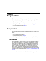
Chapter 1
Management basics
This chapter summarizes basic operational procedures in a Business Policy
Switch and provides an overview of switch management options. Topics in this
chapter include the following information:
•
•
•
Overview of management tools (next)
Setting IP parameters for management access to the switch (page 18)
Access levels and passwords (page 20)
Management tools
You can use three management tools to monitor and manage your Business Policy
Switch:
•
•
•
Device Manager software (next)
Web management interface (page 18)
Console port interface (Refer to Using the Business Policy Switch 2000.)
Device Manager
The Java-based Device Manager for the Business Policy Switches is a graphical
user interface (GUI) that allows you to manage a standalone switch or a single
switch stack. Device Manager provides the options found in other management
tools, as well as the ability to manage VLANs and MultiLink Trunks. You can
display or print statistics and other data in one of three graph formats. To use
Device Manager, you must have network connectivity to a management station
running Device Manager on one of the supported platforms. You must also assign
an IP address to the switch, as described in “Setting the switch IP parameters” on
page 18.”
Getting Started with the Business Policy Switch 2000 Management Software
18 Chapter 1 Management basics
Web management interface
The Business Policy Switch Web management interface is a Web-based graphical
user interface that you use with a Web browser to manage a standalone switch or
switch stack. You can access devices on your network from various locations
within the network.
To access the Web interface, you need a Web browser and an IP address for the
switch or switch stack. To assign the IP address to the switch, refer to “Setting the
switch IP parameters” next.
Setting the switch IP parameters
To allow management access to the switch, you must assign IP parameters for the
switch.
To set the IP parameters:
1
Connect a terminal to the Console port on the switch.
2
Set the terminal protocol as follows:
•
•
•
•
•
•
•
•
9600 baud
No parity
8 bits
1 stop bit
Flow control set to Xon/Xoff
Window Terminal Emulator option set to no
Terminal Preferences: Function, Arrow, and Control keys active
Buffer size set to 24
3
Connect the switch to power.
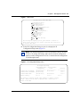
4
After the Nortel Networks logo is displayed, press [Ctrl]-Y to display the
Main Menu (Figure 1).
At first the screen displays the Main Menu for a standalone switch. Then, if
the switch is part of a stack configuration, the screen is refreshed within 20
seconds to show the Main Menu for a stack configuration. The Main Menu for
a stack configuration includes stack features (bold text in Figure 1).
209321-A
Chapter 1 Management basics 19
Figure 1 Main menu
Business Policy Switch Main Menu
IP Configuration/Setup...
SNMP Configuration...
System Characteristics...
Switch Configuration...
Console/Comm Port Configuration...
Identify Unit Numbers...
Renumber Stack Units...
Display Hardware Units...
Spanning Tree Configuration...
TELNET Configuration...
Software Download...
Configuration File...
Display Event Log
Reset
Reset to Default Settings
Logout
Use arrow keys to highlight option, press <Return> or <Enter> to
select option. Press Ctrl-R to return to previous menu. Press Ctrl-C
to return to Main Menu.
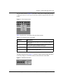
5
Select IP Configuration/Setup (or press i) to display the IP
Configuration/Setup menu (Figure 2).
Note: The default management VLAN in the Business Policy Switch is
VLAN 1. To manage the switch, make sure the network management
station is on the management VLAN or is connected to the management
VLAN through routers.
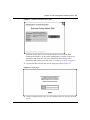
Figure 2 IP Configuration/Setup menu
IP Configuration/Setup
BootP Request Mode: [ BootP Disabled ]
Configurable
In Use
Last Boot
---------------------------------------------In-Band Stack IP Address: [xx.xx.xx.xxx]
xx.xx.xx.xxx
0.0.0.0
In-Band Switch IP Address: [xx.xx.xx.xxx]
0.0.0.0
In-Band Subnet Mask:
[255.255.255.0]
255.255.255.0
0.0.0.0
Default Gateway:
0.0.0.0
0.0.0.0
0.0.0.0
Use space bar to display choices, press <Return> or <Enter> to select
choice. Press Ctrl-R to return to previous menu. Press Ctrl-C to
return to Main Menu.
Getting Started with the Business Policy Switch 2000 Management Software
20 Chapter 1 Management basics
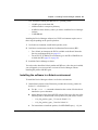
6
Do one of the following, based on your configuration:
•
For a standalone switch, enter the IP address of the switch in the In-Band
Switch IP Address field.
Note: If the In-Band Subnet Mask field does not already contain a value
when you enter the IP address in the In-Band Switch IP Address field,
the switch software provides an in-use default value for the In-Band
Subnet Mask field, based on the class of the entered IP address.
•
For a stack configuration, enter the Stack IP address in the In-Band Stack
IP Address field.
Note: The In-Band Switch IP Address field allows this switch to operate
as a standalone switch. However, this field is not required for the
operation of the stack. You cannot enter the same IP address in both
fields.
7
In the In-Band Subnet Mask field, enter the IP subnet mask address.
8
In the Default Gateway field, enter the default gateway address.
Access levels and passwords
Access to management functions for Business Policy Switches is controlled by
passwords and community strings. Different passwords or community strings
allow access to different levels of management functions.
Access to Device Manager requires entering community strings. Access to the
Web interface requires a user identification and a password.
209321-A
21
Chapter 2
Installing Device Manager software
Device Manager software is available on the Nortel Networks Services and
Support Web site as a self-extracting executable file. This chapter provides
instructions to install the Device Manager software in a Windows or UNIX
environment.
Accessing the Nortel Networks Web site
To access the Nortel Networks Services and Support Web site:
1
Go to the following URL:
www12.nortelnetworks.com/software
2
Under Switching Products, choose Business Policy Switch 2000, and
click Go.
3
Scroll down to Business Policy Switch Device Manager.
4
Follow the instructions in one of the next sections, depending on the platform
on which you will install the software.
Windows installation
The minimum system requirements for installing Device Manager on Microsoft®
Windows NT®, Windows® 95, or Windows 98 are:
•
•
•
75 MHz Pentium or 100 MHz 486 processor
16 MB DRAM
100 MB space on the hard disk
Getting Started with the Business Policy Switch 2000 Management Software
22 Chapter 2 Installing Device Manager software
To install the management software on a Windows platform:
➨ On the Business Policy Switch software Web page, click jdm_xxx.exe.
Note: In the file name, xxx represents the current version of the Device
Manager software.
The file uncompresses and installs the Java Runtime Environment (JRE) and
the Device Manager software into the appropriate directories on your system.
To run the Device Manager software:
➨ From the Windows Start menu, choose Programs > Nortel Frame Switch
Management Software > Device Manager.
UNIX installation
The minimum system requirements for installing Device Manager in a UNIX
environment are:
•
SPARC workstation running the Sun Solaris 2.5.x (or higher) operating
system
— 120 MB space on the hard disk
— 4 MB available in a temporary directory
— 60 MB free in the directory where you want to install the Device Manager
software
— 32 MB DRAM
or
•
HP workstation running the HP/UX 10.20 or 11.x operating system
— 120 MB space on the hard disk
— 4 MB available in a temporary directory
— 60 MB free in the directory where you want to install the Device Manager
software
— 32 MB DRAM
or
209321-A
Chapter 2 Installing Device Manager software 23
•
AIX workstation running the IBM AIX 4.1 operating system
— 120 MB space on the hard disk
— 4 MB available in a temporary directory
— 60 MB free in the directory where you want to install the Device Manager
software
— 32 MB DRAM
Installing the Device Manager software in a UNIX environment requires two or
three steps, depending on the specific platform:
1
In a Solaris environment, install Solaris patches (next).
2
In all three environments, install the Java Runtime Environment (JRE):
•
For a Solaris environment, the JRE is available on the Nortel Networks
Services and Support Web site (page 23).
For an HP-UX or IBM AIX environment, go to the HP or IBM Web site
to obtain the JRE (page 25 or page 26).
•
3
Install the Device Manager software.
You only need to install the Solaris patches and JRE once. After they are installed,
you can upgrade your system to later versions of Device Manager without
installing the patches and JRE again.
Installing the software in a Solaris environment
To install the Device Manager software in a Solaris environment:
1
Install Solaris patches. Nortel Networks provides the necessary patches for
Solaris 5.5.1 and Solaris 5.6.
a
Use the uname -a command to determine the version of Solaris that is
installed on your workstation.
b
On the Business Policy Switch UNIX software Web page, click one of the
following links to download the correct patches for your Solaris version:
— 1.1.8_09a_patches_sparc_5.5.1.tar for Solaris 5.5.1
— 1.1.8_09a_patches_sparc_5.6.tar for Solaris 5.6
c
For instructions to install the patches, click README.sparc_1.1.8_09a.
Getting Started with the Business Policy Switch 2000 Management Software
24 Chapter 2 Installing Device Manager software
2
3
Install the Java Runtime Environment for Solaris systems:
a
On the Business Policy Switch UNIX software Web Page, click
Solaris_JRE_1.1.8_09a_sparc.bin.
b
For instructions to install the Solaris JRE, click install_jre.txt.
Install the Device Manager software:
On the Business Policy Switch UNIX software Web page, click jdm_xxx.tar.
Note: In the file name, xxx represents the current version of the Device
Manager software.
The file uncompresses and installs the Device Manager software into the
appropriate directories on your system.
Before you run the Device Manager software, you must set the following UNIX
environment variables:
setenv JAVA_HOME <JRE installed path>
setenv PATH${JAVA_HOME}/bin:${PATH}
setenv LD_LIBRARY_PATH [JAVA_HOME}/lib/sparc/
native_thread:${LD_LIBRARY_PATH}
setenv CLASSPATH ${JAVA_HOME}/lib/rt.jar:${CLASSPATH}
To start Device Manager:
➨ Enter:
% JDM a.b.c.d
where a.b.c.d is the IP address of the device.
209321-A
Chapter 2 Installing Device Manager software 25
Installing the software in an HP-UX environment
Nortel Networks does not directly provide the JRE for HP-UX systems. However,
you can download the JRE from the HP corporate Web site.
To install the Device Manager software in an HP-UX environment:
1
Install the JRE for HP-UX:
a
Go to one of the following URLs, depending on your version of HP-UX:
— http://unixsolutions.hp.com/products/java/jre_os10118_content.html
for HP-UX 10.20
— http://unixsolutions.hp.com/products/java/jre_os10118_content.html
for HP-UX 11.x
b
2
Follow the prompts to download and install the JRE for your HP-UX
system.
Install the Device Manager software:
On the Business Policy Switch UNIX software Web page, click jdm_xxx.tar.
Note: In the file name, xxx represents the current version of the Device
Manager software.
The file uncompresses and installs the Device Manager software into the
appropriate directories on your system.
Before you run the Device Manager software, you must set the following UNIX
environment variables:
setenv JAVA_HOME <JRE installed path>
setenv PATH${JAVA_HOME}/bin:${PATH}
setenv LD_LIBRARY_PATH [JAVA_HOME}/lib/sparc/
native_thread:${LD_LIBRARY_PATH}
setenv CLASSPATH ${JAVA_HOME}/lib/rt.jar:${CLASSPATH}
Getting Started with the Business Policy Switch 2000 Management Software
26 Chapter 2 Installing Device Manager software
To start Device Manager:
➨ Enter:
% JDM a.b.c.d
where a.b.c.d is the IP address of the device.
Installing the software in an IBM AIX environment
Nortel Networks does not directly provide the JRE for IBM AIX systems.
However, you can download the JRE from the IBM corporate Web site.
To install the management software in an IBM AIX environment:
1
2
Install the JRE for IBM AIX:
a
Go to the http://www6.software.ibm.com/dl/dka/dka-p URL.
b
Follow the prompts to download and install the JRE for your IBM AIX
system.
Install the Device Manager software:
On the Business Policy Switch UNIX software Web page, click jdm_xxx.tar.
Note: In the file name, xxx represents the current version of the Device
Manager software.
The file uncompresses and installs the Device Manager software into the
appropriate directories on your system.
Before you run the Device Manager software, you must set the following UNIX
environment variables:
setenv JAVA_HOME <JRE installed path>
setenv PATH${JAVA_HOME}/bin:${PATH}
setenv LD_LIBRARY_PATH [JAVA_HOME}/lib/sparc/
native_thread:${LD_LIBRARY_PATH}
setenv CLASSPATH ${JAVA_HOME}/lib/rt.jar:${CLASSPATH}
209321-A
Chapter 2 Installing Device Manager software 27
To start Device Manager:
➨ Enter:
% JDM a.b.c.d
where a.b.c.d is the IP address of the device.
Getting Started with the Business Policy Switch 2000 Management Software
28 Chapter 2 Installing Device Manager software
209321-A
29
Chapter 3
Device Manager basics
This chapter describes basic procedures for using the Device Manager software.
The chapter includes the following information:
•
•
•
•
•
•
Instructions to start Device Manager, set the Device Manager properties, and
open a device (next)
A summary of the Device Manager user interface features and how to use
them (starting on page 34)
Instructions to view statistics and display graphs (page 43)
Instructions to use Device Manager to Telnet to a switch (page 51)
Information about the trap log (page 51)
Information about online Help (page 52)
Starting Device Manager
To start Device Manager:
➨ Do one of the following, depending upon your operating system environment:
•
•
In a Microsoft® Windows® environment, from the Windows taskbar
choose Start > Programs > Nortel Frame Switch Management Software >
Device Manager.
In a UNIX environment, verify that the Device Manager installation
directory is in your search path; then enter:
JDM
Getting Started with the Business Policy Switch 2000 Management Software
30 Chapter 3 Device Manager basics
The initial Device Manager window opens (Figure 3).
Note: On startup, Device Manager performs a DNS lookup for the
machine on which it is running. If the DNS lookup is slow or fails, the
initial Device Manager window may take up to 30 seconds to open.
Figure 3 Device Manager window
Setting the Device Manager properties
Device Manager communicates with the Business Policy Switch using Simple
Network Management Protocol (SNMP). The software is shipped with default
values set for important communication parameters, such as the polling interval,
timeout, and retry count. You may want to set the parameters before you open a
device to manage.
To set the Device Manager properties:
1
Choose Device > Properties.
The Properties dialog box opens (Figure 4).
209321-A
Chapter 3 Device Manager basics 31
Figure 4 Properties dialog box
2
Type information and select check boxes.
3
Click OK.
Table 1 describes items in the Properties dialog box.
Table 1 Properties dialog box items
Area
Item
Description
Polling
Status Interval
Interval at which statistics and status information are gathered (default is
300 seconds).
(If traps, Status
Interval)
Interval at which statistics and status information are gathered when traps
are enabled (default is 300 seconds).
Hotswap Detect
every
The interval at which Device Manager polls for module information
(default is 600 seconds).
Enable
Enables (checked) or disables (not checked) periodic polling of the device
for updated status. If polling is disabled, the switch or stack status is
updated only when you click Refresh in the chassis window.
Getting Started with the Business Policy Switch 2000 Management Software
32 Chapter 3 Device Manager basics
Table 1 Properties dialog box items (continued)
Area
Item
Description
SNMP
Retry Count
Number of times Device Manager retransmits polling information.
Timeout
Length of each retry of each polling waiting period. When accessing the
device through a slow link, you may want to increase the timeout interval
and then change the Retransmission Strategy to superlinear.
Trace
Enables (checked) or disables (not checked) SNMP tracing. When Trace
is selected, SNMP protocol data units (PDUs) are displayed in the
Device > Log dialog box.
Register for Traps Specifies whether or not Device Manager should automatically register to
receive traps when Device Manager is launched against a switch.
Max Traps in Log
The specified number of traps that can exist in the trap log (default is
500).
Trap Port
Specifies the UDP port that Device Manager will listen on to receive
SNMP traps.
Confirm row
deletion
When this check box is selected, a confirmation dialog box is displayed
when you try to delete a row from a Device Manager table.
Opening a device
“Opening” a device displays the device view, a picture of the device. To open the
device view, you must enter community strings that determine the access level
granted to the device. Table 2 shows the default access community strings for the
Device Manager software.
Table 2 SNMP community string default values
209321-A
Access level
Description
Read-only
public
Read-write
private
Read-write-all
secret
Chapter 3 Device Manager basics 33
To display the device view:
1
Do one of the following:
•
•
•
Choose Device > Open.
Choose Device > Open Last, and select an IP address from the list.
Click the folder icon in the Device Manager window.
•
Press [Ctrl] + O.
The Open Device dialog box opens (Figure 5).
Figure 5 Open Device dialog box
Table 3 describes the items in the Open Device dialog box.
Table 3 Open Device dialog box items
Item
Description
Device Name
Either an IP address or a DNS name for the device, entered by the
user.
Read Community
SNMP read community string for the device. Default is public
(displayed as ******). The entry is case-sensitive.
Write Community
SNMP write community string for the device. Default is private
(displayed as *******).The entry is case-sensitive.
2
In the Device Name text box, type the DNS name or IP address of the device.
Getting Started with the Business Policy Switch 2000 Management Software
34 Chapter 3 Device Manager basics
3
In the Read Community and Write Community text boxes, type the proper
community strings (Table 2 on page 32).
Note: To gain Read-Write-All access to a device in Device Manager,
you must enter the Read-Write-All community string for both the Read
Community and Write Community strings.
4
Click Open.
Device Manager automatically determines what version of software the
selected device is running and displays the appropriate Device Manager
dialog boxes. The Device Manager window opens, showing a picture of the
device (Figure 6) that represents the physical features of the device.
Figure 6 Device view
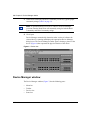
Device Manager window
The Device Manager window (Figure 7) has the following parts:
•
•
•
•
209321-A
Menu bar
Toolbar
Device view
Status bar
Chapter 3 Device Manager basics 35
Figure 7 Parts of the Device Manager window
Menu bar
Toolbar
Device view
Status bar
Menu bar
Use the menu bar to set up and operate Device Manager (Table 4).
Table 4 Menu bar commands
Command
Description
Device
Opens the Open Device dialog box.
Edit
Opens edit dialog boxes for selected objects in the device view (refer to
“Selecting objects” on page 37). This command also opens dialog boxes
for managing files and running diagnostic tests.
Graph
Opens statistics dialog boxes for the selected object.
VLAN
Opens dialog boxes for managing VLANs, spanning tree groups (STGs),
and Multi-Link Trunks.
Rmon
Opens RMON configuration and monitoring dialog boxes.
Actions
Provides quick opening of a Telnet session without going through other
dialog boxes.
Help
Opens online Help topics for Device Manager and provides a legend for
the port colors in the device view.
Getting Started with the Business Policy Switch 2000 Management Software
36 Chapter 3 Device Manager basics
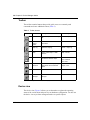
Toolbar
The toolbar contains buttons that provide quick access to commonly used
commands and some additional actions (Table 5).
Table 5 Toolbar buttons
Button
Name
Description
Menu bar equivalent
Open Device Opens the Open Device dialog
box.
Device > Open
Refresh
Device
Status
Refreshes the device view
information.
Device > Refresh Status
Trap Log
Opens the trap log.
Device > Trap Log
Help
Opens online Help in a Web
browser.1
Help > Device
Edit Selected Displays configuration data for
the selected chassis object.
Edit > Unit
Edit > Chassis
Edit > Port
Graph
Selected
Opens statistics and graphing
dialog boxes for the selected
object
Graph > Chassis
Graph > Port
Telnet
Opens a Telnet session.
Actions > Telnet
Alarm
Manager
Opens the Rmon Alarm
Manager.
Rmon > Alarm Manager
1 If the online Help does not launch, refer to page 52.
Device view
The device view (Figure 8) allows you to determine at a glance the operating
status of the various units and ports in your hardware configuration. You also use
the device view to perform management tasks on specific objects.
209321-A
Chapter 3 Device Manager basics 37
Selecting objects
The types of objects contained in the device view are:
•
•
•
•
A standalone switch (called a unit in the menus and dialog boxes)
A switch stack (called a chassis in the menus and dialog boxes)
A media dependent adapter (MDA) (called a unit in the menus and dialog
boxes)
A port
Figure 8 Objects in the device view
Switch unit or
chassis object
Port object
MDA object
Selecting a single object
To select a single object:
➨ Click the edge of the object.
The object is outlined in yellow, indicating that it is selected. Subsequent
activities in Device Manager refer to the selected object.
Getting Started with the Business Policy Switch 2000 Management Software
38 Chapter 3 Device Manager basics
Selecting multiple objects
To select multiple objects of the same type (such as ports or switches of the same
type):
➨ Do one of the following:
•
•
For a block of contiguous ports, drag to select the group of ports.
For multiple ports, MDAs, or switches in the stack, [Ctrl]-click on the
objects.
Note: In a switch stack that contains Business Policy Switches and
BayStack switches, you can select only one type of switch at a time.
To select all the ports in a standalone switch or in a switch stack:
➨ Choose Edit > Select > Ports.
To select all the “units” (switches and MDAs, but not ports):
➨ Choose Edit > Select > Units.
To select an entire stack:
➨ Choose Edit > Select > Chassis.
Viewing information about an MDA
To view information about an MDA:
1
Select the MDA.
2
Choose Edit > Unit.
The Edit > Unit dialog box opens for the MDA (Figure 9). The Edit > Unit
dialog box describes the MDA installed in the switch.
209321-A
Chapter 3 Device Manager basics 39
Figure 9 MDA dialog box
LEDs and ports
The color of LEDs in the device view is the same as the colors of the LEDs on the
physical switch. However, the device view does not show blinking activity of the
LEDs.
For a full description of the LEDs for the Business Policy Switch, refer to Using
the Business Policy Switch 2000.
The ports on the device view are color coded to show port status. Table 6 shows
the status assigned to each color.
Table 6 Port color codes
Color
Description
Green
Port is operating.
Red
Port has been manually disabled.
Orange
Port has no link.
Light Blue
Port is in standby mode.
Dark Blue
Port is being tested.
Gray
Port is unmanageable.
In addition, the Help menu provides a legend that identifies the port colors and
their meanings (Figure 10).
Getting Started with the Business Policy Switch 2000 Management Software
40 Chapter 3 Device Manager basics
Figure 10 Port color legend
Shortcut menus
Each object in the device view has a shortcut menu that opens when you
right-click a selected object. The switch shortcut menu (Figure 11) provides
access to basic hardware information about the switch and to the graphing dialog
boxes for the switch.
Figure 11 Switch unit shortcut menu
Table 7 describes the commands on the switch unit shortcut menu.
Table 7 Switch unit shortcut menu commands
209321-A
Command
Description
Edit
Opens a read-only dialog box that provides
basic hardware information about the switch.
Graph
Opens a dialog box that displays statistics for
the switch and allows you to display the
statistics as a graph.
Chapter 3 Device Manager basics 41
The port shortcut menu (Figure 12) provides a faster path for editing and graphing
a single port; however, you can access the same options using the menu bar or the
toolbar.
Figure 12 Port shortcut menu
Table 8 describes the commands on the port shortcut menu.
Table 8 Port shortcut menu commands
Command
Descriptions
Edit
Opens a dialog box that allows you to set operating parameters
for the port.
Graph
Opens a dialog box that displays statistics for the port and
allows you to display the statistics as a graph.
Enable
Administratively brings a port up.
Disable
Administratively shuts down a port. The color of the port
changes to red in the device view.
The MDA shortcut menu (Figure 13) contains a single command, Edit, that opens
a read-only dialog box with basic hardware information about the MDA.
Figure 13 MDA shortcut menu
Getting Started with the Business Policy Switch 2000 Management Software
42 Chapter 3 Device Manager basics
Status bar
The status bar displays error and informational messages from the software
application. These messages are not related to the device being managed.
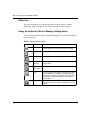
Using the buttons in Device Manager dialog boxes
Table 9 describes buttons in Device Manager dialog boxes. Not all buttons appear
in all dialog boxes.
Table 9 Device Manager buttons
Button
Name
Description
Insert
Opens a dialog box to create a new entry for a table; then
from the dialog box, inserts the new entry in the table.
Copy
Copies selected cells from a table.
Paste
Pastes copied values to a currently selected table cell.
Reset
Changes
Causes changed (but not applied) fields to revert to their
previous values.
Print Table or Prints the table or graph that is displayed.
Print Graph
209321-A
Stop
Stops the current action (compiling, saving, and so forth).
If you are updating or compiling a large data table, the
Refresh button changes to a Stop button while this action
is taking place. Clicking the Stop button interrupts the
polling process.
Export Data
Exports information to a file you specify. You can then
import this file into a text editor or spreadsheet for further
analysis.
Chapter 3 Device Manager basics 43
Editing objects
You can edit objects and values in the Device Manager device view in the
following ways:
•
Select an object and, on the toolbar, click the Edit Selected button.
The edit dialog box opens for that object.
•
From a switch or port shortcut menu, choose Edit. The edit dialog box opens
for that object.
When you change the value in a box, the changed value is displayed in bold.
However, changes are not applied to the running configuration until you click
Apply.
Note: Many dialog boxes contain a Refresh button. After you apply
changes to fields, click Refresh to display the new information in the
dialog box.
Working with statistics and graphs
Device Manager tracks a wide range of statistics for each switch, the stack
(chassis), and each port. You can view and graph statistics for a single object or
multiple objects. For information about the statistics tracked for the switch and
ports, refer to Using the Business Policy Switch 2000.
This section describes the types of statistics and graphs available, the graph dialog
boxes, and the procedure for creating a graph.
Getting Started with the Business Policy Switch 2000 Management Software
44 Chapter 3 Device Manager basics
Types of statistics
The data tables in the statistics dialog boxes list the counters, or categories of
statistics being gathered, for the specified object. For example, the categories for
ports include Interface, Ethernet Errors, Bridge, and Rmon. Each category can be
associated with six types of statistics (Table 10).
Table 10 Types of statistics
Statistic
Description
AbsoluteValue
The total count since the last time counters were reset. A system
reboot resets all counters.
Cumulative
The total count since the statistics window was first opened. The
elapsed time for the cumulative counter is displayed at the bottom of
the graph window.
Average
The cumulative count divided by the cumulative elapsed time.
Minimum
The minimum average for the counter for a given polling interval over
the cumulative elapsed time.
Maximum
The maximum average for the counter for a given polling interval over
the cumulative elapsed time.
LastValue
The average for the counter over the last polling interval.
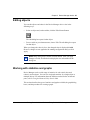
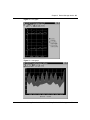
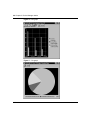
Types of graphs
With Device Manager, you can create line, area, bar, and pie graphs. Figure 14,
Figure 15, Figure 16, and Figure 17 illustrate the different graph styles,
respectively.
209321-A
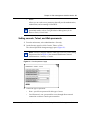
Chapter 3 Device Manager basics 45
Figure 14 Line graph
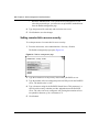
Figure 15 Area graph
Getting Started with the Business Policy Switch 2000 Management Software
46 Chapter 3 Device Manager basics
Figure 16 Bar graph
Figure 17 Pie graph
209321-A
Chapter 3 Device Manager basics 47
Statistics for single and multiple objects
Statistics for a selected object or objects are displayed in the statistics dialog box.
The dialog box for a single object shows all six types of statistics for each counter
(Figure 18).
Figure 18 Interface statistics for a single port
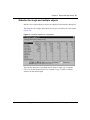
The statistics dialog box for multiple objects shows a single type of statistics
(Table 10) for the selected objects. For example, Figure 19 shows LastValue
statistics for the selected ports.
Getting Started with the Business Policy Switch 2000 Management Software
48 Chapter 3 Device Manager basics
Figure 19 Interface statistics for multiple ports
Statistics type
To change the type of statistics displayed, select a different type from the show list
at the bottom of the dialog box.
The statistics are updated based on the poll interval shown at the bottom of the
dialog box. You can select a different polling interval.
Buttons for bar, pie, and line graphs are located at the bottom of a statistics dialog
box. See the next section, “Viewing statistics as graphs,” for instructions to use
these buttons.
You can export the statistics to a tab-separated file format and import the file into
other applications. To export the information, use the Export Data button below
the table.
209321-A
Chapter 3 Device Manager basics 49
Viewing statistics as graphs
To create a graph for an object:
1
Select the object or objects to be graphed (see “Selecting objects” on
page 37).
2
Do one of the following:
•
On the toolbar, click Graph Selected.
•
•
From the shortcut menu for the object, choose Graph.
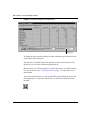
From the main menu, choose Graph > Chassis or Graph > Port.
A statistics dialog box opens with tabs for different categories of statistics for
the selected object (Figure 20).
Figure 20 Statistics dialog box for a port
3
Select a tab for the group of statistics you want to view.
4
On the displayed data table, drag to select the cells you want to graph. (They
must be in the same row or column.)
Getting Started with the Business Policy Switch 2000 Management Software
50 Chapter 3 Device Manager basics
5
Click one of the graph buttons at the bottom of the dialog box (see “Types of
graphs” on page 44).
A graph dialog box opens for the selected graph type.
6
To print a copy of the graph, click Print.
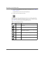
Buttons at the top of the graph dialog boxes for line, area, and bar graphs allow
you to change the orientation of the graph, change the scale, or change the graph
type. Table 11 describes the buttons in the graph dialog boxes.
Table 11 Graph dialog box buttons
Button
209321-A
Name
Description
Stacked
“Stacks” data quantities instead of displaying them
side-by-side.
Horizontal
Rotates the graph 90 degrees.
Log Scale
Changes the scale of the x-axis (of an unrotated graph)
from numeric to logarithmic.
Line Chart
Converts an area graph or bar graph to a line graph.
Area Chart
Converts a line graph or bar graph to an area graph.
Bar Chart
Converts a line graph or area graph to a bar graph.
Chapter 3 Device Manager basics 51
Telneting to a switch
From Device Manager, you can initiate a Telnet session to the console interface
for the switch or stack you are currently accessing.
To Telnet to a switch:
➨ Do one of the following:
•
•
From the Device Manager main menu, choose Actions > Telnet.
On the toolbar, click the Telnet button.
A Telnet window to the switch opens.
Trap log
You can configure a Business Policy Switch to send SNMP generic traps. When
Device Manager is running, any traps received are recorded in the trap log. You
set the maximum number of entries in the trap log using the Properties window
(page 30). The default number of trap log entries is 500.
To view the trap log:
➨ Do one of the following:
•
On the toolbar, click the Trap Log button.
•
From the Device Manager Main Menu, choose Device > Trap Log.
Note: When you operate Device Manager from a UNIX platform, you
must be logged in as root in order to receive traps.
Getting Started with the Business Policy Switch 2000 Management Software
52 Chapter 3 Device Manager basics
By default, traps are sent in SNMP V2c format. However, if you are using an
older network management system (NMS), one that supports only SNMP V1
traps (HP OpenView), you can specify that the traps be sent in V1 format.
Management stations operating with Device Manager are automatically added to
trap receivers.
For more information about traps and trap receivers, refer to Using the Business
Policy Switch 2000.
Online Help
Online Help in Device Manager is context-sensitive. You use a Web browser to
display online Help. The Web browser should launch automatically when you
click the Help button. If the Help topic you are accessing is not displayed in your
browser, exit the existing browser session and click the Help button again. If, for
some reason, the Web browser does not launch, the default locations of the Help
files are the directories listed in Table 12.
Table 12 Help file locations
209321-A
Platform
Default path
Windows 95, Windows 98, or Windows NT
c:\jnm\help\dm\dm.html
UNIX
DM-UNIX/DM/help/dm/dm.html
53
Chapter 4
Web management interface basics
A Business Policy Switch includes a Web management interface that lets you
monitor your switch through a World Wide Web browser from anywhere on the
network. The Web interface provides many of the same monitoring and
configuration features as the Device Manager software.
This chapter provides an overview of the Web management interface and its
navigation features. For information about specific Web management pages,
check the online Help in the Web management interface. For information about
using the Web management interface to configure and manage the switch, refer to
Using Web-Based Management for the Business Policy Switch 2000.
This chapter contains information about the following topics:
•
•
•
Requirements (this page)
Accessing your switch through the Web interface (page 54)
Security (page 60)
Requirements
To use the Web-based management interface you need:
•
•
•
A computer connected to any of the network ports
One of the following Web browsers installed on the computer:
— Microsoft Internet Explorer, version 4.0 or later
— Netscape Navigator, version 4.51 or later
The IP address of the switch or switch stack
Getting Started with the Business Policy Switch 2000 Management Software
54 Chapter 4 Web management interface basics
Note: As long as you have a route to the switch and there are no filters or
access policies in effect, you should be able to monitor the switch using the
Web interface.
For instructions to set the IP address of the switch, refer to “Setting the switch IP
parameters” on page 18.
Access to the Web management interface must also be enabled for the switch (the
default setting) using the console interface. For information about enabling Web
access, refer to Using the Business Policy Switch 2000.
Accessing the Web interface
Before you log in to the Web management interface, use the console interface to
verify the VLAN port assignments and to make sure that the switch CPU and your
computer are assigned to the same VLAN. If the devices are not connected to the
same VLAN, the IP address of the switch will not open the home page.
To access the Web interface:
1
Start your Web browser.
2
In the Web address field of your Web browser, type the switch IP address, and
press [Enter].
If this is the first time you are logging in to the Web management interface,
the System Information home page opens (Figure 21).
209321-A
Chapter 4 Web management interface basics 55
Figure 21 System Information home page
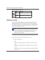
Network security does not yet exist the first time you access the Web
management interface. As the system administrator, you must create access
parameters and passwords. For more information about setting access
parameters and system passwords, refer to “Setting up security” on page 60.
3
If passwords have already been set, the login page opens (Figure 22).
Figure 22 Login page
4
In the Username text box, type ro for read-only access or rw for read-write
access.
Getting Started with the Business Policy Switch 2000 Management Software
56 Chapter 4 Web management interface basics
5
In the Password text box, type your password.
6
Click Log On.
The System Information home page opens.
With Web access enabled, the switch can support up to four concurrent Web page
users. Two pre-defined user levels are available, and each user level has a
corresponding user name and password.
Table 13 shows the two pre-defined user levels available and their corresponding
access levels in the Web management interface.
Table 13 User levels in the Web management interface
User level
User name
Password
Access level
Read-only
ro
XXXXXXXX
Read-only
Read-write
rw
XXXXXXXX
Full read/write access
Information is available online about the Web management interface. To access
more information about the Web management interface:
➨ Do one of the following:
•
•
Click Support > Help to view the entire Help file.
For context-sensitive Help, click the Help button on any page to view
information specifically about that page.
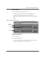
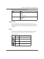
Web page layout
All the Web management pages for the Business Policy Switch have a common
layout (Figure 23). Each is divided into two sections: the menu and the content
area. All Web pages are optimized for an 800 x 600 pixel screen size.
209321-A
Chapter 4 Web management interface basics 57
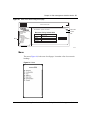
Figure 23 Parts of the Web management page
Web browser toolbar
Administration > System Information
Menu
Summary
Configuration
Fault
Statistics
Application
Administration
System Info(option)
Security
Logout
Reset
Support
Business Policy Switch 2000
BayStack 460 HW:AB3 FW:V0.2E
sysDescription SW:v1.0.0.33
sysUpTime
35 Minutes, 29 Seconds
sysName
sysLocation
sysContact
?
Help button
Content
area
9794EA
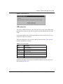
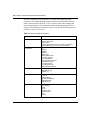
Menu
The menu (Figure 24) is the same for all pages. It contains a list of seven main
headings.
Figure 24 Menu
Getting Started with the Business Policy Switch 2000 Management Software
58 Chapter 4 Web management interface basics
The first six headings provide options for viewing and configuring switch
parameters. The Support heading provides options to open the online Help file
and the Nortel Networks Web site. Table 14 lists the main menu headings and
their associated options. For detailed information about managing the switch
using the Web management interface, refer to Using Web-Based Management for
the Business Policy Switch 2000.
Table 14 Menu headings and options
209321-A
Heading
Option
Summary
Stack Information
Switch Information
Switch View
Identify Unit Numbers (only for a stack configuration)
Stack Numbering (only for a stack configuration)
Configuration
IP
System
SNMPv1
SNMPv3
SNMP Trap
MAC Address Table
Find MAC Address
Port Management
High Speed Flow Control
Software Download
Configuration File
Console/Comm Port
Stack Operational Mode
Fault
RMON Threshold
RMON Event Log
System Log
Statistic
Port
Interface
Ethernet Errors
Transparent Bridging
RMON Ethernet
RMON History
Application
Port Mirroring
Rate Limiting
IGMP
VLAN
Spanning Tree
MultiLink Trunk
QoS
COPS
Chapter 4 Web management interface basics 59
Table 14 Menu headings and options (continued)
Heading
Option
Administration
System Information
Security
Logout
Reset
Reset to Defaults
Support
Help
Release Notes
Manuals
Upgrade
Content area
The content area displays tables of information with buttons that you use to
configure and monitor the switch. Some tables may be too big to fit the displayed
page area. In these cases, use the scroll bars at the side and bottom to view the
entire table.
Icons
Some pages contain icons that allow you to modify information in a statistical
table or to display statistics in chart format. Table 15 describes the icons.
Table 15 Page icons
Icon
Name
Description
Modify
Modifies the row.
Help
Opens online Help.
Delete
Deletes a row.
Pie chart
Displays the statistics as a pie chart.
Getting Started with the Business Policy Switch 2000 Management Software
60 Chapter 4 Web management interface basics
Table 15 Page icons (continued)
Icon
Name
Description
Bar graph
Displays statistics as a bar graph.
Line graph
Displays statistics as a line graph.
Setting up security
To set passwords and RADIUS (Remote Authentication Dial In User Service)
authentication settings for the for the switch or stack, use the Security pages.
These pages allow you to create or modify the passwords of a standalone switch
or any switches within the stack framework, and allow you to set the security
parameters for remote dial access users.
Note: Nortel Networks recommends that when you install the switch,
you set the initial system passwords using the console interface. After
that, you can update them using the Web management interface. For
information about using the console interface, refer to Using the
Business Policy Switch 2000.
To set console, Web, and Telnet passwords and RADIUS authentication settings:
➨ From the main menu, choose Administration > Security.
Four options are displayed:
•
Web
Allows you to define Web password settings in switch or stack mode.
•
Telnet
Allows you to define Telnet password settings in switch or stack mode.
•
Console
Allows you to define console password settings in switch (stand alone) or
stack mode.
209321-A
Chapter 4 Web management interface basics 61
•
Radius
Allows you to set the server parameters that will provide authentication,
authorization, and accounting for RADIUS.
Note: For information on setting switch (standalone) or stack
operational modes, refer to Using Web-Based Management for the
Business Policy Switch 2000.
Setting console, Telnet, and Web passwords
1
From the main menu, select Administration > Security.
2
On the Security page list, click Console, Telnet, or Web.
The selected password management page opens (Figure 25).
Note: The title of the page indicates which type of access you are setting
the password for. In Figure 25, the network administrator selected
Administration > Security > Console.
Figure 25 Console password page
3
Choose the type of password:
•
•
None—specifies no password for this type of access
Local Password—sets a password for access through direct network
connection or a direct Console port connection
Getting Started with the Business Policy Switch 2000 Management Software
62 Chapter 4 Web management interface basics
•
RADIUS Authentication—sets a password for remote dial-in. If you
select this password type, you must also set up RADIUS authentication
from the Radius management page.
4
Type the password for read-only and read-write user access.
5
Click Submit to save the changes.
Setting remote dial-in access security
To set the parameters for remote dial-in access security:
1
From the main menu, select Administration > Security > Radius.
The Radius management page opens (Figure 26).
Figure 26 Radius management page
209321-A
2
Type the IP addresses of the primary and secondary RADIUS servers.
3
Type the number of the user datagram protocol (UDP) port for the RADIUS
server. The default value is 1645.
4
Type a character string for the RADIUS Shared Secret. This parameter is a
special switch security code that provides authentication to the RADIUS
server. The value can be any contiguous ASCII string that contains at least
one printable character, up to a maximum of 35.
5
Click Submit.
63
Index
A
Copy button 42
AbsoluteValue statistics 44
Cumulative statistics 44
customer support 16
access levels 20, 32, 56
Actions menu 35
AIX installation of Device Manager 26
D
Alarm Manager button 36
data, exporting 48
Area Chart button 50
default access community strings 32
area graph example 45
Device Manager
installing on UNIX 22
installing on Windows 21
requirements 17
setting properties 30
starting 29
summary 17
Average statistics 44
B
Bar Chart button 50
bar graph example 46
Device Manager window 30
blinking LEDs 39
Device menu 35
buttons
dialog boxes 42
toolbar 36
Device Name parameter 33
device view
displaying 33
summary 36
C
device, opening 33
color-coded ports 39
communication parameters, setting for Device
Manager 30
Disable command 41
disabled port, color 39
community strings
default 32
entering 33
E
Confirm row deletion parameter 32
Edit menu 35
console passwords 60
Edit Selected button 36
content area, Web page 59
Enable command 41
conventions, text 14
Export Data button 42, 48
Edit command 40, 41
Getting Started with the Business Policy Switch 2000 Management Software
64 Index
G
graph
creating 49
modifying 50
line graph example 45
link, lacking, color 39
Log Scale button 50
login window 55
Graph command 40, 41
graph dialog box 50
M
Graph menu 35
Main Menu, console 19
Graph Selected button 36, 49
Max Traps in Log field 32
graph types 44
Maximum statistics 44
H
MDA
shortcut menu 41
viewing 38
Help button 36
Help menu 35
Help, Device Manager 52
Horizontal button 50
Hotswap Detect every parameter 31
HP/UX installation of Device Manager 25
media dependent adapter. See MDA
menu bar, Device Manager 35
menu, Web 57
menus. See individual menu names
Microsoft Internet Explore, software version 53
Minimum statistics 44
I
multiple objects, selecting 38
If traps, status interval parameter 31
N
Insert button 42
installation, Device Manager 21
IP parameters, setting 18
J
Netscape Navigator, software version 53
network security
at first login 55
setting up 60
new table entry, creating 42
JRE (Java Runtime Environment)
installing for HP-UX 25
installing for IBM AIX 26
installing for Solaris 24
O
L
objects
editing 43
selecting 37
LastValue statistics 44
layout, Web page 56
LEDs in device view 39
legend, port color 35, 39
Line Chart button 50
209321-A
object types 37
online Help 35, 52
Open Device button 33, 36
Open Device dialog box 33, 35
operating port, color 39
Index 65
P
Paste button 42
requirements
Device Manager 17
UNIX installation of Device Manager 22
Web management interface 18, 53
Windows installation of Device Manager 21
patches, Solaris 23
Reset Changes button 42
pie graph example 46
Retry Count parameter 32
polling interval 48
Rmon menu 35
password management pages 61
passwords 20, 56, 60
polling interval, setting 31
polling waiting period 32
S
shortcut menus
MDA 41
port 41
switch unit 40
port color legend 39
port shortcut menu 41
ports
color-coded 39
disabled 39
selecting 38
single object, selecting 37
SNMP tracing 32
Print button 42
SNMP traps 51
product support 16
software installation
AIX 26
HP/UX 23
Solaris 23
UNIX 22
Windows 21
Properties dialog box 30
publications
hard copy 16
related 15
Solaris installation of Device Manager 23
R
Solaris patches, installing 23
Radius authentication 61
Stacked button 50
Radius management page 62
standalone switch, setting IP parameters 20
Read Community parameter 33
standby port, color 39
Read Community, SNMP 34
statistics
for a single object 47
for multiple objects 48
graphing 43
types 44
read-only access 62
read-write access 62
Read-Write-All access 34
Refresh Device Status button 36
release notes, obtaining 58
statistics dialog box
multiple objects 48
single object 47
remote dial-in access 62
statistics dialog boxes 35
Register for Traps parameter 32
Status Interval parameter 31
Status Poll Enable parameter 31
Getting Started with the Business Policy Switch 2000 Management Software
66 Index
status polling 31
Stop button 42
U
support Web site 21
UNIX
installing Device Manager 22
receiving traps 51
support, Nortel Networks 16
UNIX environment variables 25
switch stack, selecting 38
switch stack, setting IP parameters 20
UNIX environment variables for Device Manager
24
switch unit shortcut menu 40
unmanageable port, color 39
switch, selecting 37
user levels 56
Support heading 58
System Information home page 54
V
T
value, changed 43
technical publications 16
versions, Web browsers 53
technical support 16
VLAN menu 35
Telnet button 36, 51
Telnet passwords 60
W
Telnet session 35, 36, 51
Web Help file, accessing 58
tested port, color 39
Timeout parameter 32
Web management interface
description 18
opening 54
requirements 18
timeout, setting 32
Web management interface requirements 53
toolbar, Device Manager 36
Web management options 58
Trace parameter 32
Web passwords 60
trap log 51
Web site, Services and Support 21
Trap Log button 36
window, Device Manager 30, 34
Trap Port parameter 32
Windows installation for Device Manager 21
troubleshooting
adjusting polling waiting period 32
locations of Help files 52
opening the Web home page 54
receiving traps 51
selecting switches in device view 38
setting UNIX environment variables 25
Write Community parameter 33
text conventions 14
types of objects 37
209321-A
Write Community, SNMP 34