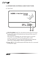
1
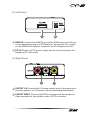
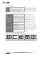
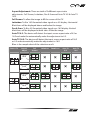
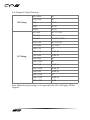
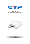
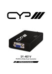
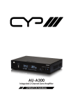
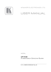
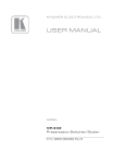
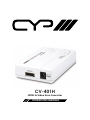
CV-401H HDMI to Video Scan Converter OPERATIONS MANUAL DISCLAIMERS The information in this manual has been carefully checked and is believed to be accurate. CYP (UK) Ltd assumes no responsibility for any infringements of patents or other rights of third parties which may result from its use. CYP (UK) Ltd assumes no responsibility for any inaccuracies that may be contained in this document. CYP (UK) Ltd also makes no commitment to update or to keep current the information contained in this document. CYP (UK) Ltd reserves the right to make improvements to this document and/or product at any time and without notice. COPYRIGHT NOTICE No part of this document may be reproduced, transmitted, transcribed, stored in a retrieval system, or any of its part translated into any language or computer file, in any form or by any means—electronic, mechanical, magnetic, optical, chemical, manual, or otherwise—without express written permission and consent from CYP (UK) Ltd. © Copyright 2011 by CYP (UK) Ltd. All Rights Reserved. Version 1.1 August 2011 TRADEMARK ACKNOWLEDGMENTS All products or service names mentioned in this document may be trademarks of the companies with which they are associated. SAFETY PRECAUTIONS Please read all instructions before attempting to unpack, install or operate this equipment and before connecting the power supply. Please keep the following in mind as you unpack and install this equipment: • Always follow basic safety precautions to reduce the risk of fire, electrical shock and injury to persons. • To prevent fire or shock hazard, do not expose the unit to rain, moisture or install this product near water. • Never spill liquid of any kind on or into this product. • Never push an object of any kind into this product through any openings or empty slots in the unit, as you may damage parts inside the unit. • Do not attach the power supply cabling to building surfaces. • Use only the supplied power supply unit (PSU). Do not use the PSU if it is damaged. • Do not allow anything to rest on the power cabling or allow any weight to be placed upon it or any person walk on it. • To protect the unit from overheating, do not block any vents or openings in the unit housing that provide ventilation and allow for sufficient space for air to circulate around the unit. REVISION HISTORY VERSION NO. DATE SUMMARY OF CHANGE VR0 25/04/2011 Preliminary Release VS1 25/04/2012 Updated format/diagrams CONTENTS 1. Introduction�������������������������������������������6 2. Applications�������������������������������������������6 3. Package Contents����������������������������������6 4. System Requirements���������������������������6 5. Features��������������������������������������������������7 6. Operation Controls and Functions�������8 6.1 Top Panel������������������������������������������������������ 8 6.2 Left Panel������������������������������������������������������ 9 6.3 Right Panel��������������������������������������������������� 9 6.3 OSD Menu��������������������������������������������������10 6.4 Support Input Timing����������������������������12 7. Connection Diagram�������������������������� 13 8. Specifications�������������������������������������� 14 9. Acronyms��������������������������������������������� 15 1. INTRODUCTION T he CV-401H is a HDMI to Video Scan Converter is designed to convert digital signal from HDMI source to an analogue Composite Video (CVBS) signal for use in an NTSC or PAL system, with additional L/R stereo audio output. This device provides a convenient conversion that allows the user to convert high definition video to standard resolution (480i or 576i) format, and then store on DVR or VCR machine. The device is HDMI 1.2 & DVI 1.0 compliant and features a simple On Screen Display (OSD) menu, motion adaptive 3-D de-interlacing, 3D noise reduction, frame rate conversion, and adaptive contrast enhancement. 2. APPLICATIONS • Convert HDMI video signal to a NTSC or PAL signal • Convert digital audio signal to analog audio signal 3. PACKAGE CONTENTS • HDMI to Video Scan Converter • 5 V/1 A DC Power Adaptor • Operation Manual 4. SYSTEM REQUIREMENTS Video source equipment such as a Digital Camera or PC with HDMI output port, display (TV or monitor) with composite video & L/R audio input ports, HDMI cable and RCA cables. 6 5. FEATURES • HDMI 1.2 and DVI 1.0 compliant • Converts video signal from HDMI source to NTSC or PAL signal • Converts digital audio from HDMI source to analog stereo audio • Accepts a wide range of HDTV input resolutions from 480i to 1080p, and PC resolutions from VGA@60Hz to WUXGA@60Hz (RB) • Output picture can be of Underscan or Overscan aspect ratio • Motion adaptive 3-D de-interlacing with pixel-by-pixel motion adaptive interpolation • 3D noise reduction in both temporal and spatial domain • Adaptive contrast enhancement Note: This device does NOT convert HDCP. When receiving content that has HDCP encryption there will be no video output. 7 6. OPERATION CONTROLS AND FUNCTIONS 6.1 Top Panel 1 2 1 NTSC/PAL MENU (Hold): Press this button to bring up the On-Screen Display (OSD) which will display the input timing and the output TV format information. When the OSD is displayed, press the button again to switch the output TV system from NTSC to PAL and from PAL to NTSC. Press this button for 3 seconds the OSD will bring up the selection menu. Press it sequentially to select the required setting. 2 Power LED: This LED will illuminate in RED when the unit is connected to the power supply. 8 6.2 Left Panel 1 2 1 HDMI IN: Connect the HDMI IN port to the HDMI output port of your source equipment such as a DVD player or Set-top box. You can also use an HDMI to DVI cable to connect to the DVI output of your PC. 2 DC 5V: Plug the 5 V DC power supply into the unit and connect the adaptor to AC wall outlet. 6.3 Right Panel 1 2 1 OUTPUT L/R: Connect the L/R stereo output ports to the input ports of active speakers or TV/monitor with corresponding audio inputs. 2 OUTPUT VIDEO: Connect the VIDEO output port to the composite video input port of your display such as HDTV or monitor. 9 6.3 OSD Menu IN 1280×960 @60 (Input Timing) OUT NTSC (Output TV System) Press the Menu button once to bring up the OSD and display the input (IN) & Output (OUT) information. NTSC Press the Menu button PAL for 3 seconds to bring up the OSD then press Underscan 1 it repeatedly to move Underscan 2 the OSD cursor to the Overscan Aspect Adj desired selection. Once Full Screen the selection is made, if Letterbox no button is pressed for a few seconds, the display Pan & Scan on the OSD will disappear Auto TV 4:3 and the display will output the selected display Auto TV 16:9 mode. Below is the example of the scan selection result. 4:3 Source 10 TV Underscan1 Underscan2 Overscan Aspect Adjustment: There are total of 5 different aspect ratio adjustments: Full Screen, Letterbox, Pan & Scan and Auto TV 4:3 & Auto TV 16:9. Full Screen: To allow the image to fill the screen of the TV. Letterbox: To fit a 16:9 formatted video signal on a 4:3 display. Horizontal Black bars will be displayed above and below the image Pan & Scan: To fit a 4:3 formatted video signal on a 16:9 display. Vertical black bars will be displayed at both sides of the the image. Auto TV 4:3: The device will detect the input source aspect ratio of 4:3 or 16:9 and make the automatically make the adjustment to 4:3. Auto TV 16:9: The device will detect the input source aspect ratio of 16:9 or 4:3 and automatically make the adjustment to 16:9. Blow is the sample chart of the selection result: Source TV 4:3 Aspect Adjust Full Screen Letterbox Pan&Scan 4:3 × × 16:9 × 16:9 × Auto TV 16:9 × × × 4:3 16:9 Auto TV 4:3 × × × 11 6.4 Support Input Timing HD Timing PC Timing 480i/480p 60 576i/576p 50 720p 50,60 1080i 50,60 1080p 50,60 640×480 60,72,75,85 720×400 70 800×600 56,60,72,75,85 1024×768 60,70,75,85 1152×864 70,75,85 1280×720 60 1280×768 60RB,60 1280×800 60RB,60 1280×960 60 1280×1024 60 1366×768 60RB,60 1400×1050 60RB,60 1440×900 60RB,60 1600×1200 60 1680×1050 60RB,60 1920×1200 60RB Note: When the input timing is not supported, the OSD will display “IN Not Support”. 12 7. CONNECTION DIAGRAM HDMI Source DVD or Blu-ray Player HDMI Output Power Supply Stereo Analogue Audio CVBS (Composite) Cable TV 13 8. SPECIFICATIONS Input Port 1×HDMI Output Ports 1×CVBS (Composite Video) 1×L/R Stereo RCA Jacks (Analog Audio) HDMI Input Audio LPCM 2Ch, 48kHz Output Video NTSC/PAL Output Audio Stereo L/R ESD Protection Human body model: ±8 kV (air-gap discharge) ±6 kV (contact discharge) Power Supply 5 V DC/1 A linear power adaptor (US/ EU standards, CE/FCC/UL certified) or 5V/1.2A switching power adaptor (with universal plug, CE/FCC/UL certified) Dimensions 114 mm (W)×65 mm (D)×26 mm (H) Weight 120 g Chassis Material Plastic Silkscreen Color White Operating Temperature 0 °C~40 °C/32 °F~104 °F Storage Temperature −20 °C~60 °C/−4 °F~140 °F Power Consumption 4.7 W Relative Humidity 20~90 % RH (non-condensing) 14 9. ACRONYMS ACRONYM COMPLETE TERM CAT5e Category 5 Cable CAT6 Category 6 cable CEC Consumer Electronics Control DVI Digital Visual Interface HDCP High-bandwidth Digital content protection HDMI High Definition Multimedia Interface IR Infrared 15 CYP (UK) Ltd., Unit 7, Shepperton Business Park, Govett Avenue, Shepperton, Middlesex, TW17 8BA Tel: +44 (0) 20 3137 9180 | Fax: +44 (0) 20 3137 6279 Email: [email protected] www.cypeurope.com