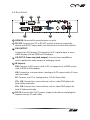
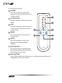
1
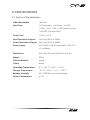
CP-255ID CV, SV, VGA and DVI to DVI Scaler / Converter OPERATION MANUAL DISCLAIMERS The information in this manual has been carefully checked and is believed to be accurate. CYP (UK) Ltd assumes no responsibility for any infringements of patents or other rights of third parties which may result from its use. CYP (UK) Ltd assumes no responsibility for any inaccuracies that may be contained in this document. CYP (UK) Ltd also makes no commitment to update or to keep current the information contained in this document. CYP (UK) Ltd reserves the right to make improvements to this document and/or product at any time and without notice. COPYRIGHT NOTICE No part of this document may be reproduced, transmitted, transcribed, stored in a retrieval system, or any of its part translated into any language or computer file, in any form or by any means—electronic, mechanical, magnetic, optical, chemical, manual, or otherwise—without express written permission and consent from CYP (UK) Ltd. © Copyright 2011 by CYP (UK) Ltd. All Rights Reserved. Version 1.1 August 2011 TRADEMARK ACKNOWLEDGMENTS All products or service names mentioned in this document may be trademarks of the companies with which they are associated. SAFETY PRECAUTIONS Please read all instructions before attempting to unpack, install or operate this equipment and before connecting the power supply. Please keep the following in mind as you unpack and install this equipment: • Always follow basic safety precautions to reduce the risk of fire, electrical shock and injury to persons. • To prevent fire or shock hazard, do not expose the unit to rain, moisture or install this product near water. • Never spill liquid of any kind on or into this product. • Never push an object of any kind into this product through any openings or empty slots in the unit, as you may damage parts inside the unit. • Do not attach the power supply cabling to building surfaces. • Use only the supplied power supply unit (PSU). Do not use the PSU if it is damaged. • Do not allow anything to rest on the power cabling or allow any weight to be placed upon it or any person walk on it. • To protect the unit from overheating, do not block any vents or openings in the unit housing that provide ventilation and allow for sufficient space for air to circulate around the unit. REVISION HISTORY VERSION NO. DATE SUMMARY OF CHANGE v1.00 First release 17/04/2013 CONTENTS 1. Introduction�������������������������������������������6 2. Applications�������������������������������������������6 3. Package Contents����������������������������������6 4. System Requirements���������������������������6 5. Features��������������������������������������������������7 6. Operation Controls and Functions�������8 6.1 Front Panel��������������������������������������������������� 8 6.2 Rear Panel����������������������������������������������������� 9 6.3 Remote Control����������������������������������������10 6.4 RS-232 Protocols��������������������������������������11 6.5 RS-232 Commands����������������������������������12 6.6 OSD MENU�������������������������������������������������14 7. Connection Diagram�������������������������� 18 8. Specifications�������������������������������������� 19 8.1 Technical Specifications������������������������19 8.2 Resolution Support���������������������������������20 9. Acronyms��������������������������������������������� 22 1. INTRODUCTION T he CP-255ID is a Digital Video Scaler designed to accept Composite Video, S-Video, PC, and DVI input signals. These inputs can be switched and scaled and are outputted via DVI port. External audio input signals can be switched and sent to the L/R output port correspondingly with the video source selection. The control can be done through on-panel buttons, IR remote, or RS-232, and there is OSD (On Screen Menu) providing selection and system information. The device provides full range of output resolutions, up to 1080p for HDTV timing, and WUXGA (RB) for PC timing. The control can be done through onpanel buttons, IR remote, or RS-232, and there is OSD (On Screen Menu) providing selection and system information. 2. APPLICATIONS Analogue to Digital video signal conversion Analogue and Digital Source Integration Upscaling Standard definition video for High-Definition displays 3. PACKAGE CONTENTS Digital Video Scaler Remote Control (CR-118) Power Adaptor Operation Manual 4. SYSTEM REQUIREMENTS Source equipment such as PC/Laptop or DVD Player with HDMI to DVI adaptor, analogue sources via standard cabling and DVI display with active speakers and connection cables. 6 5. FEATURES Supports the conversion of multiple video and audio formats to DVI Supports synchronized output for input video and output audio signals Supports 3D de-interlacing, noise reduction and Comb filter Supports frame rate conversion Supports control via RS-232, IR Remote handset and front panel controls 7 6. OPERATION CONTROLS AND FUNCTIONS 6.1 Front Panel DIGITAL VIDEO SCALER CP-255ID POWER XGA CV SV PC DVI MENU - + ENTER 720P 1 2 3 4 5 1 POWER & LED: Press this button to switch the device ON or to put the device into standby mode. When the device is connected to an active power supply the LED will illuminate and the device will switch ON automatically. 2 IR (IR window): Receives only the IR signal from the supplied remote control. 3 INPUT button and LEDs (CV/SV/PC/DVI): Press to directly select the required input. An LED will illuminate to indicate the currently selected source. 4 MENU: Press this button to enter into the on-screen menu (OSD). 5 −/+ (Minus/Plus): Use these buttons to navigate down and up in the on-screen menu. 6 ENTER: Press this button to confirm the selection. Note: Pressing '−' (MINUS) and ENTER simultaneously will immediately switch the output resolution of the device to 720p60. Pressing '+' (PLUS) and ENTER simultaneously will immediately switch the output resolution of the device to XGA. 8 6.2 Rear Panel 1 2 4 IN SERVICE RS232 DVI OUT 3 L/R OUT DVI L/R PC L SV R DC 5V CV 5 6 1 SERVICE: Reserved for manufacturer use only. 2 RS-232: Connect to a PC or RS-232 control system to control the device with RS232 commands (see Sectionsm 6.5 and 6.6 for details). 3 DVI OUTPUT: Connect to a DVI display (TV/monitor) for PC signal output or to an HDMI display with an HDMI to DVI adaptor. 4 L/R OUT (3.5 mm mini-jack output): Connect to an amplifier or active speaker for audio output in analogue stereo. 5 IN (Inputs): DVI: Connect to DVI source such as PC or Laptop or to a HDMI source with a HDMI to DVI adaptor. L/R: Connect to a source device's analogue (L/R) output with a 3.5 mm mini-jack cable. PC: Connect to a PC or Laptop with a D-Sub 15pin cable. CV + L/R: Connect to a source device such as video/DVD player for both video and audio. SV + L/R: Connect to a source device such as video/DVD player for both S-Video and audio. 6 DC 5V: Connect the 5 V DC power supply to the device and plug the adaptor into an AC wall outlet. 9 6.3 Remote Control 1 POWER: Press this button to switch the device ON or to put the device into standby mode POWER 2 CV/SV/PC/DVI: CV Press to directly select the required input. SV Press this button to exit the menu or the current selection in the onscreen menu. DVI 3 EXIT 4 MENU: Press this button to enter the onscreen menu. 2 PC 3 EXIT: MENU 5 AUTO ADJUST Press the button to optimize the positioning of the picture (picture centering) on the screen. CR-118 7 OK & : Press OK to confirm the selection or use the directional buttons to navigate the on-screen menus. 10 6 7 Press this button to return the device to the factory default settings. 6 AUTO ADJUST: 4 OK RESET 5 RESET: 1 6.4 RS-232 Protocols CP-255ID Remote Control PIN Assignment PIN Assignment 1 NC 1 NC 2 Tx 2 Rx 3 Rx 3 Tx 4 NC 4 NC 5 GND 5 GND 6 NC 6 NC 7 NC 7 NC 8 NC 8 NC 9 NC 9 NC ► ◄ Baud Rate: 9600bps Data bit: 8 bits Parity: None Flow Control: None Stop Bit: 1 11 6.5 RS-232 Commands Command Description Contents S SOURCE 1~4 Select input source 1=DVI 2=VIDEO 3=S-VIDEO 4=PC R SOURCE Inquire input source Reports the numerical equivilent for SOURCE setting (as above) S OUTPUT 0~25 Select output timing 0=Native 1=640×480 2=800×6003=1024×768 4=1280×768 5=1360×768 6=1280×720 7=1280×800 8=1280×1024 9=1440×900 10=1400×1050 11=1680×1050 12=1600×1200 13=1920×1080 16=1920×1200 17=480p 18=720p 60 19=1080p 60 20=1080i 60 22=576p 23=720p 50 24=1080p 50 25=1080i 50(25) R OUTPUT Inquire output timing Reports the numerical equivilent for OUTPUT setting (as above) S SIZE 0~6 Select output size 0=OVERSCAN 1=FULL 2=BEST FIT 3=PAN SCAN 4=LETTER BOX 5=UNDER 2 6=UNDER 1 R SIZE Inquire output size Reports the numerical equivilent for SIZE setting (as above) S PCAUTO I PC Mode / Auto Setup S CONTRAST 0~60 Contrast Setting R CONTRAST Inquire contrast setting S BRIGHTNESS 0~60 Brightness setting R BRIGHTNESS Inquire brightness setting S HUE 0~60 Hue setting 12 Command Description Contents R HUE Inquire hue setting S SATURATION 0~60 Saturation setting R SATURATION Inquire saturation setting S SHARPNESS 0~30 Sharpness setting R SHARPNESS Inquire sharpness setting S NR 0~3 Noise reduction setting 0=OFF / 1=LOW / 2=MIDDLE / 3=HIGH R NR Inquire noise reduction Reports the numerical equivilent for the setting NR setting (as above) S AUDIODELAY 0~3 Audio delay setting 0=OFF / 1=40ms / 2=110ms(2) / 3=50ms R AUDIODELAY Inquire audio delay setting Reports the numeric equivilent for S AUDIOMUTE 0/1 Audio mute setting R AUDIOMUTE Inquire audio mute setting S KEY LOCK 0/1 Key lock setting 0=ENABLE / 1=DISABLE R KEY LOCK Inquire key lock setting Reports the numeric equivilent for KEY AUDIODELAY setting (as above) 0=ON / 1=MUTE LOCK setting (as above) FW Firmware checking S RESET 1 Pre-reset S POWER 0/1 Power On/Off 0=OFF / 1=ON R POWER Power Status Reports the numeric equivilent for POWER setting (as above) Note: RS-232 commands will be not executed unless followed with a carriage return and LF. Commands are case-insensitive. 13 6.6 OSD MENU 1st Layer 2nd layer 3rd Layer DISPLAY OUTPUT Native 640×480 60 800×600 60 1024×768 60 1360×768 60 1280×720 60 1280×800 60 1280×1024 60 1440×900 60 1400×1050 60 1680×1050 60 1600×1200 60 1920×1080 60 1920×1200 60 720×480P 60 1280×720P 60 1920×1080I 60 1920×1080P 60 720×576P 50 1280×720P 50 1920×1080I 50 1920×1080P 50 14 4th Layer 1st Layer 2nd layer 3rd Layer SIZE (VIDEO mode only) OVER SCAN 4th Layer FULL BEST FIT PAN SCAN LETTER BOX UNDER 2 UNDER 1 MODE INFO INFO ON OFF PC(PC mode only) AUTO SETUP No YES H_POSITION 0~60 (30) V_POSITION 0~60 (30) PHASE CLOCK WXGA/XGA XGA WXGA RESET NO YES 15 1st Layer 2nd layer 3rd Layer 4th Layer COLOUR COLOUR R 0~1023 (512) G 0~1023 (512) B 0~1023 (512) R OFFSET 0~1023 (512) G OFFSET 0~1023 (512) B OFFSET 0~1023 (512) CONTRAST 0~60 (30) BRIGHTNESS 0~60 (30) HUE (VIDEO mode only) 0~60 (30) SATURATION (VIDEO mode only) 0~60 (30) SHARPNESS (VIDEO mode only) 0~30 (0) NR. (VIDEO mode only) OFF LOW MIDDLE HIGH AUDIO VOLUME 0~100 DELAY (L/R output only) OFF 40 ms 110 ms 150 ms SOUND ON MUTE 16 1st Layer 2nd layer 3rd Layer SETUP FACTORY RESET NO 4th Layer YES KEY LOCK OFF ON POWER SAVE OFF ON INFORMATION INPUT OUTPUT REVISION Note: Items in Bold are the Factory default settings. Items in brackets are the default values for those settings 17 7. CONNECTION DIAGRAM DVD Player RS-232 Equipped PC or Laptop Analogue Stereo Input RS-232 Composite Video Input Analogue Stereo Output S-Video Input IN SERVICE RS232 DVI OUT L/R OUT DVI L/R PC L SV R DC 5V CV AV Receiver Power Supply DVI Output VGA & Analogue Stereo Input DVI Input TV or Monitor PC or Laptop 18 PC or Laptop 8. SPECIFICATIONS 8.1 Technical Specifications Video Bandwidth 165 MHz Input Ports 1×Composite, 1×S-Video, ,1×VGA, 1×DVI, 1×L/R, 1×LR, 1×USB (service only), 1×RS-232 (Control Only) Output Port 1×DVI, 1×L/R Input Resolution Support Up to WUXGA & 1080p Output Resolution Support Up to WUXGA & 1080p Power Supply 5V/2.6A DC (US/EU standards, CE/FCC/ UL certified) Dimensions 215 mm (W)×165 mm(D)×47 mm (H) Weight 970 g Chassis Material Metal Colour Black Operating Temperature 0 ˚C ~ 40 ˚C / 32 ˚F ~ 104 ˚F Storage Temperature −20 ˚C ~ 60 ˚C / −4 ˚F ~ 140 ˚F Relative Humidity 20 ~ 90% RH (non-condensing) Power Consumption 5.7 W 19 8.2 Resolution Support Input Resolution PC DVI/HDMI CV/SV NTSC PAL VGA640×480 (@60/72/75 Hz) SVGA800×600 (@56/60/72/75 Hz) XGA1024×768 (@60/70/75 Hz) XGA+1152×864 @75 Hz 1280×720 @60 Hz 1280×768 @60 Hz 1280×800 @60 Hz 1280×960 @60 Hz 1280×1024 (@60/75 Hz) 1360×768 @60 Hz SXGA+1400×1050 @60 Hz WXGA+1440×900 @60 Hz UXGA1600×1200 @60 Hz WSXGA1680×1050 RB @60 Hz 1920×1080@60 Hz 1920×1200 RB@60 Hz 480i/576I 480p/576p 720p(@50/60 Hz) 1080i(@50/60 Hz) 1080p(@24/30/50/60 Hz) 20 DVI/HDMI output Resolution Native 640×480@60 Hz 800×600@60 Hz 1024×768@60 Hz 1360×768@60 Hz 1280×720@60 Hz 1280×800@60 Hz 1280×1024@60 Hz 1440×900@60 Hz 1400×1050@60 Hz 1680×1050@60 Hz 1600×1200@60 Hz 1920×1080@60 Hz 1920×1200@60 Hz 480p 576p 720p (@50/60 Hz) 1080i (@50/60 Hz) 1080p (@50/60 Hz) 21 9. ACRONYMS ACRONYM COMPLETE TERM COMP Component Video CV Composite Video DVI Digital Visual Interface RGB Red Green Blue SV S-Video VGA Video Graphics Array UXGA Ultra Extended Graphics Array WUXGA Widescreen Ultra Extended Graphics Array 22 CYP (UK) Ltd., Unit 7, Shepperton Business Park, Govett Avenue, Shepperton, Middlesex, TW17 8BA Tel: +44 (0) 20 3137 9180 | Fax: +44 (0) 20 3137 6279 Email: [email protected] www.cypeurope.com v1.00