1
MIXER / MICROPHONE PREAMPLIFIER
REFERENCE
MANUAL
2002
Important Safety Instructions
Important Safety
Instructions
Important Safety Instructions
(English)
Safety symbols used in this product
This symbol alerts the user that there are important
operating and maintenance instructions in the literature
accompanying this unit.
This symbol warns the user of uninsulated voltage within
the unit that can cause dangerous electric shocks.
This symbol warns the user that output connectors contain
voltages that can cause dangerous electrical shock.
Please follow these precautions
when using this product:
1.
2.
3.
4.
5.
6.
7.
8.
9.
10.
11.
Read these instructions.
Keep these instructions.
Heed all warnings.
Follow all instructions.
Do not use this apparatus near water.
Clean only with a damp cloth. Do not spray any liquid cleaner
onto the faceplate, as this may damage the front panel controls
or cause a dangerous condition.
Install in accordance with the manufacturer's instructions.
Do not install near any heat sources such as radiators, heat
registers, stoves, or other apparatus (including amplifiers) that
produce heat.
Do not defeat the safety purpose of the polarized or
grounding-type plug. A polarized plug has two blades with
one wider than the other. A grounding-type plug has two
blades and a third grounding prong. The wide blade or the
third prong are provided for your safety. When the provided
plug does not fit into your outlet, consult an electrician for
replacement of the obsolete outlet.
Protect the power cord from being walked on or pinched,
particularly at plugs, convenience receptacles, and the point
where they exit from the apparatus.
Use only attachments or accessories specified by the
manufacturer.
Important Safety Instructions
12. Use only with a cart, stand, bracket, or table designed for use
with professional audio or music equipment. In any
installation, make sure that injury or damage will not result
from cables pulling on the apparatus and its mounting. If a
cart is used, use caution when moving the cart/apparatus
combination to avoid injury from tip-over.
13. Unplug this apparatus during lightning storms or when unused
for long periods of time.
14. Refer all servicing to qualified service personnel. Servicing is
required when the apparatus has been damaged in any way,
such as when the power-supply cord or plug is damaged, liquid
has been spilled or objects have fallen into the apparatus, the
apparatus has been exposed to rain or moisture, does not
operate normally, or has been dropped.
15. This unit produces heat when operated normally. Operate in a
well-ventilated area with at least six inches of clearance from
peripheral equipment.
16. This product, in combination with an amplifier and
headphones or speakers, may be capable of producing sound
levels that could cause permanent hearing loss. Do not
operate for a long period of time at a high volume level or at a
level that is uncomfortable. If you experience any hearing loss
or ringing in the ears, you should consult an audiologist.
17. Do not expose the apparatus to dripping or splashing. Do not
place objects filled with liquids (flower vases, soft drink cans,
coffee cups) on the apparatus.
18. WARNING: To reduce the risk of fire or electric shock, do
not expose this apparatus to rain or moisture.
Important Safety Instructions
Instructions de Sécurité Importantes
(French)
Symboles utilisés dans ce produit
Ce symbole alèrte l’utilisateur qu’il existe des instructions
de fonctionnement et de maintenance dans la documentation
jointe avec ce produit.
Ce symbole avertit l’utilisateur de la présence d’une
tension non isolée à l’intérieur de l’appareil pouvant engendrer des
chocs électriques.
Ce symbole prévient l'utilisateur de la présence de tensions
sur les raccordements de sorties, représentant un risque
d'électrocution.
Veuillez suivre ces précautions
lors de l’utilisation de
l’appareil:
1.
2.
3.
4.
5.
6.
7.
8.
9.
10.
11.
Lisez ces instructions.
Gardez ces instructions.
Tenez compte de tous les avertissements.
Suivez toutes les instructions.
N’utilisez pas cet allareil à proximité de l’eau.
Ne nettoyez qu’avec un chiffon humide. Il est potentiellement
dangereux d'utiliser des pulvérisateurs ou nettoyants liquides
sur cet appareil.
Installez selon les recommandations du constructeur.
Ne pas installer à proximilé de sources de chaleur comme
radiateurs, cuisinière ou autre appareils (don’t les
amplificateurs) produisant de la chaleur.
Ne pas enlever la prise de terre du cordon secteur. Une prise
murale avec terre deux broches et une troisièrme reliée à la
terre. Cette dernière est présente pour votre sécurité. Si le
cordon secteur ne rentre pas dans la prise de courant,
demandez à un électricien qualifié de remplacer la prise.
Evitez de marcher sur le cordon secteur ou de le pincer, en
particulier au niveau de la prise, et aux endroits où il sor de
l’appareil.
N’utilisez que des accessoires spécifiés par le constructeur.
Important Safety Instructions
Suite de la page suivante
12. N’utilisez qu’avec un stand, ou table conçus pour l’utilisation
d’audio professionnel ou instruments de musique. Dans toute
installation, veillez de ne rien endommager à cause de câbles
qui tirent sur des appareils et leur support.
13. Débranchez l’appareil lors d’un orage ou lorsqu’il n’est pas
utilisé pendant longtemps.
14. Faites réparer par un personnel qualifié. Une réparation est
nécessaire lorsque l’appareil a été endommagé de quelque sorte
que ce soit, par exemple losrque le cordon secteur ou la prise
sont endommagés, si du liquide a coulé ou des objets se sont
introduits dans l’appareil, si celui-ci a été exposé à la pluie ou à
l’humidité, ne fonctionne pas normalement ou est tombé.
15. Puisque son fonctionement normale génère de la chaleur,
placez cet appareil au moins 15cm. des équipments
péripheriques et assurez que l’emplacement permet la
circulation de l’air.
16. Ce produit, utilisé avec un amplificateur et un casque ou des
enceintes, est capable de produite des niveaux sonores pouvant
engendrer une perte permanente de l’ouïe. Ne l’utilisez pas
pendant longtemps à un niveau sonore élevé ou à un niveau
non confortable. Si vous remarquez une perte de l’ouïe ou un
bourdonnement dans les oreilles, consultez un spécialiste.
17. N'exposez pas l'appareil à l'égoutture ou à l'éclaboussement.
Ne placez pas les objets remplis de liquides (vases à fleur,
boîtes de boisson non alcoolique, tasses de café) sur l'appareil.
18. AVERTISSEMENT: Pour réduire le risque du feu ou de
décharge électrique, n'exposez pas cet appareil à la pluie ou à
l'humidité.
Important Safety Instructions
Lesen Sie bitte die folgende Sicherheitshinweise
(German)
Sicherheit Symbole verwendet in
diesem Produkt
Dieses Symbol alarmiert den Benutzer, daß es wichtige
Funktionieren und Wartung Anweisungen in der Literatur gibt, die
diese Maßeinheit begleitet.
Dieses Symbol warnt den Benutzer der nicht isolierten
Spannung innerhalb der Maßeinheit, die gefährliche elektrische
Schläge verursachen kann.
Dieses Symbol warnt den Benutzer, dem Ausgabestecker
Spannungen enthalten, die gefährlichen elektrischen Schlag
verursachen können.
Folgen Sie bitte diesen
Vorkehrungen, wenn dieses Produkt
verwendet wird:
1.
2.
3.
4.
5.
6.
7.
8.
9.
10.
11.
Lesen Sie die Hinweise.
Halten Sie sich an die Anleitung.
Beachten Sie alle Warnungen.
Beachten Sie alle Hinweise.
Bringen Sie das Gerät nie mit Wasser in Berührung.
Verwenden Sie zur Reinigung nur ein weiches Tuch.
Verwenden Sie keine flüssigen Reinigungsmittel. Dies kann
gefährliche Folgen haben.
Halten Sie sich beim Aufbau des Gerätes an die Angaben des
Herstellers.
Stellen Sie das Gerät nich in der Nähe von Heizkörpern,
Heizungsklappen oder anderen Wärmequellen (einschließlich
Verstärkern) auf.
Verfehlen Sie nicht den Zweck des grounging Terminals auf
dem Netzstecker. Dieses Terminal wird für Ihre Sicherheit zur
Verfügung gestellt.
Verlegen Sie das Netzkabel des Gerätes niemals so, daß man
darüber stolpern kann oder daß es gequetscht wird.
Benutzen Sie nur das vom Hersteller empfohlene Zubehör.
Important Safety Instructions
Fortsetzung auf nächster Seite
12. Verwenden Sie ausschließlich Wagen, Ständer, oder Tische, die
speziell für professionelle Audio- und Musikinstrumente
geeignet sind. Achten Sie immer darauf, daß die jeweiligen
Geräte sicher installiert sind, um Schäden und Verletzungen zu
vermeiden. Wenn Sie einen Rollwagen benutzen, achten Sie
darauf, das dieser nicht umkippt, um Verletzungen
auszuschließen.
13. Ziehen Sie während eines Gewitters oder wenn Sie das Gerät
über einen längeren Zeitraum nicht benutzen den Netzstecher
aus der Steckdose.
14. Die Wartung sollte nur durch qualifiziertes Fachpersonal
erfolgen. Die Wartung wird notwendig, wenn das Gerät
beschädigt wurde oder aber das Stromkabel oder der Stecker,
Gegenstände oder Flüssigkeit in das Gerät gelangt sind, das
Gerät dem Regen oder Feuchtigkeit ausgesetzt war und
deshalb nicht mehr normal arbeitet oder heruntergefallen ist.
15. Dieses Gerät produziert auch im normalen Betrieb Wärme.
Achten Sie deshalb auf ausreichende Lüftung mit mindestens
15 cm Abstand von anderen Geräten.
16. Dieses Produkt kann in Verbindung mit einem Verstärker und
Kopfhörern oder Lautsprechern Lautstärkepegel erzeugen, die
anhaltende Gehörschäden verursachen. Betreiben Sie es nicht
über längere Zeit mit hoher Lautstärke oder einem Pegel, der
Ihnen unangenehm is. Wenn Sie ein Nachlassen des Gehörs
oder ein Klingeln in den Ohren feststellen, sollten Sie einen
Ohrenarzt aufsuchen.
17. Setzen Sie den Apparat nicht Bratenfett oder dem Spritzen
aus. Plazieren Sie die Nachrichten, die mit Flüssigkeiten
(gefüllt werden Blumevases, Getränkdosen, Kaffeetassen)
nicht auf den Apparat.
18. WARNING: um die Gefahr des Feuers oder des elektrischen
Schlages zu verringern, setzen Sie diesen Apparat nicht Regen
oder Feuchtigkeit aus.
Important Safety Instructions
CE Declaration Of Conformity
See our website at:
http://www.alesis.com
FCC Compliance Statement
This device complies with Part 15 of the FCC rules. Operation is
subject to the following two conditions: (1) This device may not
cause harmful interference and (2) this device must accept any
interference received, including interference that may cause
undesired operation.
NOTE: This equipment has been tested and found to comply with
the limits for a Class B digital device, pursuant to Part 15 of the
FCC Rules. These limits are designed to provide reasonable
protection against harmful interference in a residential installation.
This equipment generates, uses and can radiate radio frequency
energy and, if not installed and used in accordance with the
instructions, may cause harmful interference to radio
communications. However, there is no guarantee that interference
will not occur in a particular installation. If this equipment does
cause harmful interference to radio or television reception, which
can be determined by turning the equipment off and on, the user
is encouraged to try to correct the interference by one or more of
the following measures:
-- Reorient or relocate the receiving antenna.
-- Increase the separation between the equipment and receiver.
-- Connect the equipment into an outlet on a circuit different from
that to which the receiver is connected.
-- Consult the dealer or an experienced radio/TV technician for
help.
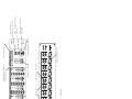
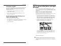
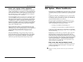
Power In
Power Switch
Aux Send 2
(Post Fader)
Aux Send 1
(Pre Fader)
Low Frequency EQ
High Frequency EQ
Tape Monitor In
Phantom Power Switch
120 50-60
5
HZ
2 3W MAX
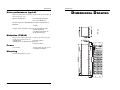
REAR PANEL
Monitor Out
Channel Fader
Line In
Aux Sends
Main Out
Stereo Aux Return
Main Out
Channel
Pan/Balance
FRONT PANEL
Gain
Channel Insert
Headphone Jack
Master Level
Microphone In
Master Fader
Phantom Power
Indicator
Monitor Select
Switch
Phones/Monitor
Level
Stereo Aux
Return Level
Introduction
TABLE
OF
CONTENTS
AUX System: Effects Send/Receive............................................................30
How to Set Aux Send and Return Levels .......................................30
Using the meter..............................................................................................32
Avoiding noise................................................................................................33
System noise (ground loops, hum, induced noise).......................33
Table of Contents ................................................................. 1
Applications...........................................................................37
Introduction.............................................................................3
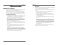
Multitrack recording......................................................................................37
Tracking/Overdubbing.....................................................................37
Mixdown..............................................................................................38
Using the HIGH and LOW EQ controls......................................................39
Monitoring AUX 1 in the PHONES jack .....................................................40
The Alesis Multimix 12R Microphone Preamplifier/Mixer........................3
Using this manual.............................................................................................3
Grounding Instructions...................................................................................4
Installation ...............................................................................5
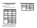
Troubleshooting...................................................................41
Unpacking .........................................................................................................5
AC power..........................................................................................................5
Grounding.............................................................................................5
Use clean power ...................................................................................6
Power switch.........................................................................................6
Mounting...........................................................................................................6
Troubleshooting Index..................................................................................41
Maintenance/Service.....................................................................................43
Exterior cleaning.................................................................................43
Specifications ....................................................................... 45
Frequency Response......................................................................................45
Connectors......................................................................................................45
Levels ...............................................................................................................46
Impedance.......................................................................................................46
Noise performance (typical).........................................................................47
Distortion (THD+N).......................................................................................47
Power...............................................................................................................47
Mounting.........................................................................................................47
Connections .............................................................................7
Inputs .................................................................................................................7
Cable common sense...........................................................................7
Microphone Inputs...............................................................................8
Phantom power....................................................................................9
Line-level devices (synthesizers, CD players, video)....................10
TAPE IN jacks .....................................................................................12
Phonograph turntables .....................................................................13
Do not connect any of the following to any input of the
Multimix 12R!......................................................................................13
How to connect effect devices and signal processors...............................14
Effects via Aux Send and Aux Return .............................................14
In-line processing using the INSERT jacks (compressors &
equalizers) ...........................................................................................15
Outputs ............................................................................................................18
To a stereo PA system or instrument amplifier ............................18
To a mono system..............................................................................18
To a stage monitor (foldback) system ............................................18
To another mixer................................................................................19
To a stereo tape recorder..................................................................19
To an ADAT multitrack recorder.....................................................20
Phones..................................................................................................23
Monitor Out ........................................................................................23
Dimensional Drawing .......................................................48
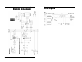
Block diagram .....................................................................49
Level diagram.................................................................................................50
Index ........................................................................................ 51
Operating Instructions ......................................................25
Before turning the mixer on, "zero out' the controls................................25
Setting input trim levels ................................................................................26
PEAK LED method ............................................................................26
Metering/Unity Gain method..........................................................27
Typical Fader and Control Levels................................................................28
Proper gain staging of other equipment........................................29
Multimix 12R Reference Manual
Introduction
1
Introduction
TABLE
OF
CONTENTS
AUX System: Effects Send/Receive............................................................30
How to Set Aux Send and Return Levels .......................................30
Using the meter..............................................................................................32
Avoiding noise................................................................................................33
System noise (ground loops, hum, induced noise).......................33
Table of Contents ................................................................. 1
Applications...........................................................................37
Introduction.............................................................................3
Multitrack recording......................................................................................37
Tracking/Overdubbing.....................................................................37
Mixdown..............................................................................................38
Using the HIGH and LOW EQ controls......................................................39
Monitoring AUX 1 in the PHONES jack .....................................................40
The Alesis Multimix 12R Microphone Preamplifier/Mixer........................3
Using this manual.............................................................................................3
Grounding Instructions...................................................................................4
Installation ...............................................................................5
Troubleshooting...................................................................41
Unpacking .........................................................................................................5
AC power..........................................................................................................5
Grounding.............................................................................................5
Use clean power ...................................................................................6
Power switch.........................................................................................6
Mounting...........................................................................................................6
Troubleshooting Index..................................................................................41
Maintenance/Service.....................................................................................43
Exterior cleaning.................................................................................43
Specifications ....................................................................... 45
Frequency Response......................................................................................45
Connectors......................................................................................................45
Levels ...............................................................................................................46
Impedance.......................................................................................................46
Noise performance (typical).........................................................................47
Distortion (THD+N).......................................................................................47
Power...............................................................................................................47
Mounting.........................................................................................................47
Connections .............................................................................7
Inputs .................................................................................................................7
Cable common sense...........................................................................7
Microphone Inputs...............................................................................8
Phantom power....................................................................................9
Line-level devices (synthesizers, CD players, video)....................10
TAPE IN jacks .....................................................................................12
Phonograph turntables .....................................................................13
Do not connect any of the following to any input of the
Multimix 12R!......................................................................................13
How to connect effect devices and signal processors...............................14
Effects via Aux Send and Aux Return .............................................14
In-line processing using the INSERT jacks (compressors &
equalizers) ...........................................................................................15
Outputs ............................................................................................................18
To a stereo PA system or instrument amplifier ............................18
To a mono system..............................................................................18
To a stage monitor (foldback) system ............................................18
To another mixer................................................................................19
To a stereo tape recorder..................................................................19
To an ADAT multitrack recorder.....................................................20
Phones..................................................................................................23
Monitor Out ........................................................................................23
Dimensional Drawing .......................................................48
Block diagram .....................................................................49
Level diagram.................................................................................................50
Index ........................................................................................ 51
Operating Instructions ......................................................25
Before turning the mixer on, "zero out' the controls................................25
Setting input trim levels ................................................................................26
PEAK LED method ............................................................................26
Metering/Unity Gain method..........................................................27
Typical Fader and Control Levels................................................................28
Proper gain staging of other equipment........................................29
Multimix 12R Reference Manual
Introduction
1
Introduction
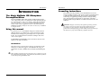
INTRODUCTION
Grounding Instructions
The Alesis Multimix 12R Microphone
Preamplifier/Mixer
The Alesis Multimix 12R is a high-quality, rack-mountable 12-input,
stereo output audio mixer. It is designed to handle eight microphones,
two stereo line inputs, and to route signal to and from external effect
processing devices. As a basic, easy-to-understand mixer, it can be
used in a wide variety of applications from sound reinforcement to
multitrack recording. It may also be used as an accessory or submixer
to a larger console.
Using this manual
To get the most out of your Multimix 12R, please read this manual.
While the mixer is not complicated to operate, the manual contains
information that will help you get the highest level of performance
from it. We’ve included creative alternative techniques that aren't
obvious at first glance.
To find what you need quickly, refer to the index at the back of the
manual, or the Table of Contents.
Conventions
The buttons, knobs, and rear panel connectors are referred to in this
manual just as their names appear on the Multimix 12R, using all
capital letters (Example: [TRIM] control, [PAN] knob, [PHONES] jack,
etc.).
✪
When something important appears in the manual, an icon (like the one on the
left) will appear in the left margin. This symbol indicates that this information
is vital when operating the Multimix 12R.
Multimix 12R Reference Manual
Introduction
3
This product must be grounded. If it should malfunction or break
down, grounding provides a path of least resistance for electric current
to reduce the risk of electric shock. This product is equipped with a
cord having an equipment-grounding conductor and a grounding
plug. The plug must be plugged into an appropriate outlet that is
properly installed and grounded in accordance with all local rules and
ordinances.
DANGER - Improper connection of the equipment-grounding conductor
can result in a risk of electric shock. Check with a qualified electrician or
serviceman if you are in doubt as to whether the product is properly
grounded. Do not modify the plug provided with the product; if it will not fit
the outlet, have a proper outlet installed by a qualified electrician.
Introduction
INTRODUCTION
Grounding Instructions
The Alesis Multimix 12R Microphone
Preamplifier/Mixer
The Alesis Multimix 12R is a high-quality, rack-mountable 12-input,
stereo output audio mixer. It is designed to handle eight microphones,
two stereo line inputs, and to route signal to and from external effect
processing devices. As a basic, easy-to-understand mixer, it can be
used in a wide variety of applications from sound reinforcement to
multitrack recording. It may also be used as an accessory or submixer
to a larger console.
Using this manual
To get the most out of your Multimix 12R, please read this manual.
While the mixer is not complicated to operate, the manual contains
information that will help you get the highest level of performance
from it. We’ve included creative alternative techniques that aren't
obvious at first glance.
To find what you need quickly, refer to the index at the back of the
manual, or the Table of Contents.
Conventions
The buttons, knobs, and rear panel connectors are referred to in this
manual just as their names appear on the Multimix 12R, using all
capital letters (Example: [TRIM] control, [PAN] knob, [PHONES] jack,
etc.).
✪
When something important appears in the manual, an icon (like the one on the
left) will appear in the left margin. This symbol indicates that this information
is vital when operating the Multimix 12R.
Multimix 12R Reference Manual
Introduction
3
This product must be grounded. If it should malfunction or break
down, grounding provides a path of least resistance for electric current
to reduce the risk of electric shock. This product is equipped with a
cord having an equipment-grounding conductor and a grounding
plug. The plug must be plugged into an appropriate outlet that is
properly installed and grounded in accordance with all local rules and
ordinances.
DANGER - Improper connection of the equipment-grounding conductor
can result in a risk of electric shock. Check with a qualified electrician or
serviceman if you are in doubt as to whether the product is properly
grounded. Do not modify the plug provided with the product; if it will not fit
the outlet, have a proper outlet installed by a qualified electrician.
Installation
INSTALLATION
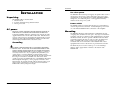
Use clean power
The Multimix 12R's internal power supply is designed to filter out most
AC line noise. However, it is still good practice to plug your sound
equipment into an AC circuit that is not shared with lighting dimmers,
refrigerators, air conditioning units, or other appliances that may
induce noise into the power system.
Unpacking
The Multimix 12R box should contain:
1. The mixer itself
2. A packet of literature along with this manual
3. An AC power cable
Power switch
The POWER switch is located on the back panel. A power indicator is
on the front panel next to the meter. Avoid turning the power switch
on or off while the Multimix 12R is connected to a live amplifier.
AC power
Mounting
READ ALL SAFETY WARNINGS IN THE PREVIOUS SECTION OF
THIS MANUAL TO ENSURE SAFE OPERATION OF THIS UNIT.
Connect the Multimix 12R to the specified power using the AC cable
supplied with the unit. The AC cable is removable. If the distance to
your AC outlet is longer or shorter than the supplied cable, you may
substitute an approved standard NEMA-to-CEE power cable of the
correct length, available from most electronics stores.
The Multimix 12R may be rack mounted in a standard EIA 19" rack,
occupying three standard 1.75" rack spaces. Any angle of orientation is
acceptable. Note that (as with most audio equipment) if it is mounted
into metal rack rails, the chassis ground of all units in the rack will be
connected together by the rail. In some cases this is desirable, but if
hum is a problem in the system, you may need to install nonconductive rack screws and washers on the Multimix 12R or other
equipment in the rack to isolate the chassis grounds from each other.
Grounding
CONNECT THE MULTIMIX 12R TO A PROPERLY GROUNDED
OUTLET ONLY. DO NOT USE ADAPTERS WHICH REMOVE THE
SAFETY GROUND PROTECTION OR CUT OFF THE GROUNDING
PRONG ON THE POWER CORD. Proper grounding is essential for
user safety and low noise. If you experience 60-cycle hum in your
sound system as a result of different ground potentials between
different units in your system, plug all units into the same AC circuit (if
the total power load allows) and make sure other devices in the
system are properly grounded themselves. The Multimix 12R features
balanced inputs and outputs, so if it is properly connected to other
balanced units, AC ground potentials will not affect the audio. If you
cannot get rid of ground loops, consult a professional electrician
familiar with sound system power designs.
Multimix 12R Reference Manual
Installation
5
The mixer may also be used on a table top. To avoid scratching a
tabletop surface, apply rubber or felt feet to the bottom of the
Multimix 12R.
Installation
INSTALLATION
Use clean power
The Multimix 12R's internal power supply is designed to filter out most
AC line noise. However, it is still good practice to plug your sound
equipment into an AC circuit that is not shared with lighting dimmers,
refrigerators, air conditioning units, or other appliances that may
induce noise into the power system.
Unpacking
The Multimix 12R box should contain:
1. The mixer itself
2. A packet of literature along with this manual
3. An AC power cable
Power switch
The POWER switch is located on the back panel. A power indicator is
on the front panel next to the meter. Avoid turning the power switch
on or off while the Multimix 12R is connected to a live amplifier.
AC power
Mounting
READ ALL SAFETY WARNINGS IN THE PREVIOUS SECTION OF
THIS MANUAL TO ENSURE SAFE OPERATION OF THIS UNIT.
Connect the Multimix 12R to the specified power using the AC cable
supplied with the unit. The AC cable is removable. If the distance to
your AC outlet is longer or shorter than the supplied cable, you may
substitute an approved standard NEMA-to-CEE power cable of the
correct length, available from most electronics stores.
The Multimix 12R may be rack mounted in a standard EIA 19" rack,
occupying three standard 1.75" rack spaces. Any angle of orientation is
acceptable. Note that (as with most audio equipment) if it is mounted
into metal rack rails, the chassis ground of all units in the rack will be
connected together by the rail. In some cases this is desirable, but if
hum is a problem in the system, you may need to install nonconductive rack screws and washers on the Multimix 12R or other
equipment in the rack to isolate the chassis grounds from each other.
Grounding
CONNECT THE MULTIMIX 12R TO A PROPERLY GROUNDED
OUTLET ONLY. DO NOT USE ADAPTERS WHICH REMOVE THE
SAFETY GROUND PROTECTION OR CUT OFF THE GROUNDING
PRONG ON THE POWER CORD. Proper grounding is essential for
user safety and low noise. If you experience 60-cycle hum in your
sound system as a result of different ground potentials between
different units in your system, plug all units into the same AC circuit (if
the total power load allows) and make sure other devices in the
system are properly grounded themselves. The Multimix 12R features
balanced inputs and outputs, so if it is properly connected to other
balanced units, AC ground potentials will not affect the audio. If you
cannot get rid of ground loops, consult a professional electrician
familiar with sound system power designs.
Multimix 12R Reference Manual
Installation
5
The mixer may also be used on a table top. To avoid scratching a
tabletop surface, apply rubber or felt feet to the bottom of the
Multimix 12R.
Connections
Connections
CONNECTIONS
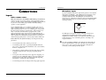
Microphone Inputs
The Alesis Multimix 12R features eight studio-grade, low-noise hybrid
microphone preamplifiers. These [MIC] jacks are designed to work
with almost any low-impedance microphone using standard 3conductor XLR connectors. The [MIC] jacks also feature 48 volt
phantom power, which may be turned on and off by the [PHANTOM]
switch on the back panel, for condenser microphones which require
external powering.
Inputs
Cable common sense
Make all connections to the Multimix 12R with the power turned off
wherever possible. If you must connect or disconnect inputs while
power is on, make sure the channel fader and [TRIM] are turned all the
way down to avoid sudden pops and clicks which may damage
speakers or other equipment.
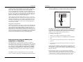
Balanced Mic Input
2
Hot
Use good-quality cable: 99% of all mixer problems turn out to be
cable or connector problems. Use the best quality cable you can, for
highest reliability and lowest noise. If something goes wrong, check
the cable and its connection to the mixer first. If the connectors are
dirty or corroded, clean them with isopropyl alcohol or other
approved electrical contact cleaner before inserting them into the
Multimix 12R. High quality cables are low-capacitance shielded cables
with a stranded (not solid) internal conductor and a low-resistance
shield. Although quality cables cost more, they do make a difference.
Ground
Cold
Socket (female)
The MIC Input is designed to accept a wide range of balanced or
unbalanced low impedance input signals, with up to 60 dB of
amplification available (which is 10 to 20 dB more than many other
rack-mount mixers). It is wired with "pin 2 hot" according to the
accepted standard.
Route cables in your system correctly by observing the following
precautions:
✪
• Do not bundle audio cables with AC power cords.
• Avoid running audio cables, or placing the Multimix 12R itself,
near sources of electromagnetic interference such as transformers,
monitors, computers, etc.
• Never unplug a cable by pulling on the wire itself. Always unplug
by firmly grasping the body of the plug and pulling directly
outward.
• Do not place cables where they can be stepped on. Stepping on a
cable may not cause immediate damage, but it can compress the
insulation between the center conductor and shield (degrading
performance), or reduce the cable’s reliability.
• Avoid twisting the cable or having it make sharp, right angle turns.
Multimix 12R Reference Manual
1
3
7
Use only one input per channel. The LINE IN jack and the MIC IN
jack of a channel can’t be used at the same time. If you turn up the
level of a line source to hear it at the same time a microphone is
connected, you may damage the microphone.
Connections
Connections
CONNECTIONS
Microphone Inputs
The Alesis Multimix 12R features eight studio-grade, low-noise hybrid
microphone preamplifiers. These [MIC] jacks are designed to work
with almost any low-impedance microphone using standard 3conductor XLR connectors. The [MIC] jacks also feature 48 volt
phantom power, which may be turned on and off by the [PHANTOM]
switch on the back panel, for condenser microphones which require
external powering.
Inputs
Cable common sense
Make all connections to the Multimix 12R with the power turned off
wherever possible. If you must connect or disconnect inputs while
power is on, make sure the channel fader and [TRIM] are turned all the
way down to avoid sudden pops and clicks which may damage
speakers or other equipment.
Balanced Mic Input
2
Hot
Use good-quality cable: 99% of all mixer problems turn out to be
cable or connector problems. Use the best quality cable you can, for
highest reliability and lowest noise. If something goes wrong, check
the cable and its connection to the mixer first. If the connectors are
dirty or corroded, clean them with isopropyl alcohol or other
approved electrical contact cleaner before inserting them into the
Multimix 12R. High quality cables are low-capacitance shielded cables
with a stranded (not solid) internal conductor and a low-resistance
shield. Although quality cables cost more, they do make a difference.
Ground
Cold
Socket (female)
The MIC Input is designed to accept a wide range of balanced or
unbalanced low impedance input signals, with up to 60 dB of
amplification available (which is 10 to 20 dB more than many other
rack-mount mixers). It is wired with "pin 2 hot" according to the
accepted standard.
Route cables in your system correctly by observing the following
precautions:
✪
• Do not bundle audio cables with AC power cords.
• Avoid running audio cables, or placing the Multimix 12R itself,
near sources of electromagnetic interference such as transformers,
monitors, computers, etc.
• Never unplug a cable by pulling on the wire itself. Always unplug
by firmly grasping the body of the plug and pulling directly
outward.
• Do not place cables where they can be stepped on. Stepping on a
cable may not cause immediate damage, but it can compress the
insulation between the center conductor and shield (degrading
performance), or reduce the cable’s reliability.
• Avoid twisting the cable or having it make sharp, right angle turns.
Multimix 12R Reference Manual
1
3
7
Use only one input per channel. The LINE IN jack and the MIC IN
jack of a channel can’t be used at the same time. If you turn up the
level of a line source to hear it at the same time a microphone is
connected, you may damage the microphone.
Connections
Phantom power
Certain types of microphones (called condenser microphones) require
a DC power supply from the mixer. “Phantom power” sends 48 volts
of DC through the microphone cable. If any of your microphones
need phantom power, turn on the [PHANTOM POWER] switch on the
Multimix 12R’s back panel to connect all the XLR MIC IN jacks to the
Multimix 12R’s internal 48 volt phantom power source. Since the
power is applied equally to pins 2 and 3, phantom power should not
affect dynamic microphones (which do not require phantom power).
However, make sure that your microphone cables have no short
circuits or intermittent connections to avoid damage to the system.
✪Avoid connecting or disconnecting any microphones while
Connections
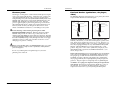
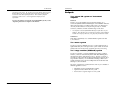
Line-level devices (synthesizers, CD players,
video)
The Multimix 12R features line-level inputs on 1/4" phone jacks which
accept standard unbalanced or balanced signals.
Unbalanced Line Input
Signal
Never connect the MIC jack to an UNBALANCED source or to a linelevel device (such as a tape recorder or synthesizer) when phantom
power is being used.
If none of your microphones need phantom power, leave the
phantom power switch off.
Tip
Hot
Tip
Cold
Ground
Tip
[PHANTOM POWER] is turned on. Make all connections with the
Multimix 12R powered off. If this is not possible, make sure the
channel's fader and [TRIM] are down, make the connections, then turn
on the [PHANTOM POWER] switch on the back panel before bringing
the fader and [TRIM] back up. Many microphones make a loud "pop"
when first powered, so make sure your faders are down to avoid
damaging your speakers or hearing.
Balanced Line Input
Sleeve
Ground
Tip
Sleeve
Ring
Ring
Sleeve
Sleeve
Unbalanced -10 dBV line level sources: Most synthesizers, drum
machines, effect devices, cassette decks and CD players operate at this
level. Their average signal level is about 1/3 of a volt. They have a 2conductor output jack that is either a 1/4" phone or "RCA phono" type.
These may be plugged directly into any of the Multimix 12R’s [LINE
IN] jacks, with the [TRIM] level set at approximately the 1 o'clock
position. Plug stereo sources such as synthesizers, CD players, and
drum machine main outputs into the STEREO LINE channels (9/10
and 11/12) if possible.
Electric guitars and basses may be plugged directly into the [LINE IN]
jacks, if you raise the [TRIM] level. The Multimix 12R has more than
enough gain (up to 50 dB when the channel fader and trim are set to
maximum) for guitars, although some pickups may sound better if
they're plugged directly into a high-impedance preamp designed for
guitar use. Plug the output of such preamps into any [LINE IN] jack.
A reminder: do not plug a line input and a microphone input into the
same channel. The inputs are not designed to handle two sources at
the same time. If you crank up the line level input to extremes to
compensate for the level loss, you may damage the microphone.
Multimix 12R Reference Manual
9
Connections
Phantom power
Certain types of microphones (called condenser microphones) require
a DC power supply from the mixer. “Phantom power” sends 48 volts
of DC through the microphone cable. If any of your microphones
need phantom power, turn on the [PHANTOM POWER] switch on the
Multimix 12R’s back panel to connect all the XLR MIC IN jacks to the
Multimix 12R’s internal 48 volt phantom power source. Since the
power is applied equally to pins 2 and 3, phantom power should not
affect dynamic microphones (which do not require phantom power).
However, make sure that your microphone cables have no short
circuits or intermittent connections to avoid damage to the system.
✪Avoid connecting or disconnecting any microphones while
Connections
Line-level devices (synthesizers, CD players,
video)
The Multimix 12R features line-level inputs on 1/4" phone jacks which
accept standard unbalanced or balanced signals.
Unbalanced Line Input
Signal
Never connect the MIC jack to an UNBALANCED source or to a linelevel device (such as a tape recorder or synthesizer) when phantom
power is being used.
If none of your microphones need phantom power, leave the
phantom power switch off.
Tip
Hot
Tip
Cold
Ground
Tip
[PHANTOM POWER] is turned on. Make all connections with the
Multimix 12R powered off. If this is not possible, make sure the
channel's fader and [TRIM] are down, make the connections, then turn
on the [PHANTOM POWER] switch on the back panel before bringing
the fader and [TRIM] back up. Many microphones make a loud "pop"
when first powered, so make sure your faders are down to avoid
damaging your speakers or hearing.
Balanced Line Input
Sleeve
Ground
Tip
Sleeve
Ring
Ring
Sleeve
Sleeve
Unbalanced -10 dBV line level sources: Most synthesizers, drum
machines, effect devices, cassette decks and CD players operate at this
level. Their average signal level is about 1/3 of a volt. They have a 2conductor output jack that is either a 1/4" phone or "RCA phono" type.
These may be plugged directly into any of the Multimix 12R’s [LINE
IN] jacks, with the [TRIM] level set at approximately the 1 o'clock
position. Plug stereo sources such as synthesizers, CD players, and
drum machine main outputs into the STEREO LINE channels (9/10
and 11/12) if possible.
Electric guitars and basses may be plugged directly into the [LINE IN]
jacks, if you raise the [TRIM] level. The Multimix 12R has more than
enough gain (up to 50 dB when the channel fader and trim are set to
maximum) for guitars, although some pickups may sound better if
they're plugged directly into a high-impedance preamp designed for
guitar use. Plug the output of such preamps into any [LINE IN] jack.
A reminder: do not plug a line input and a microphone input into the
same channel. The inputs are not designed to handle two sources at
the same time. If you crank up the line level input to extremes to
compensate for the level loss, you may damage the microphone.
Multimix 12R Reference Manual
9
Connections
Balanced +4 dBu line level sources: Professional recording and
processing equipment typically provides a balanced, 3-conductor
signal output that is a higher voltage (1.24 volts nominal level) than
most synthesizers and stereo equipment. The Multimix 12R’s [LINE
IN] jacks are designed to handle these balanced inputs.
Connections
TAPE IN jacks
The [TAPE IN] jacks on the rear panel are designed for playback of a
stereo tape deck (or any other -10 dBV level signal) through the
[MONITOR OUT] and [PHONES] jacks only. A signal at the [TAPE IN]
jacks cannot be heard from the [MAIN OUT] jacks.
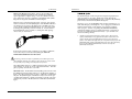
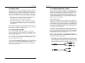
Balanced sources often feature XLR outputs. However, they should
NOT be connected to the XLR [MIC] inputs of the Multimix 12R unless
absolutely necessary, because the higher gain of the MIC jacks gives
you less headroom than the LINE IN jacks do (also, the source could
be damaged by phantom power if it's turned on). Connect them to
the [LINE IN] jacks using an XLR-to-1/4 inch phone TRS (tip-ringsleeve) cable, as shown below:
This allows you to use the Multimix 12R to monitor a mixdown to a 2track deck through your headphones. (If you plugged your mixdown
deck into the line inputs on the channels, it would cause feedback
when you press “record”.) By placing the [PHONES/MONITOR]
switch in the TAPE position, you will hear the mixer's output after it
has been passed through the mixdown deck, so you can make sure
that it is recording correctly.
•
If the proper connector cable or adapter is not available, +4 dBu line
level sources may be connected to the [MIC] jacks ONLY IF
PHANTOM POWER WILL NOT BE USED!!
Connecting a line-level output to a phantom-powered XLR input on the
Alesis Multimix 12R may cause damage to the external unit. Alesis cannot
be responsible for any damages caused by this kind of misuse.
The nominal trim setting for a +4 dBu signal plugged into a line input is
approximately 11 o'clock (12 o'clock on the stereo channels). This will
give you plenty of headroom to start with.
Maximum levels: The maximum level the [MIC] jack can receive with
the [TRIM] control full counter-clockwise is +12 dBu before clipping, so
there’s only 8 dB of headroom if you plug a +4 dBu line source into the
mic jack. The [LINE IN] jack on channels 1-8 may receive levels up to
+32 dBu without clipping, a headroom advantage of 20 dB. The stereo
channels may receive a +22 dBu (balanced or unbalanced) maximum
input.
Multimix 12R Reference Manual
11
Another use for the [TAPE IN] jacks is to play a CD or tape into a PA
system, automatically turning off all the microphones into the main PA
system when the front panel MSTR/TAPE switch is set to the TAPE
position. Note that in this application, the PA system must be fed from the
MONITOR OUT instead of the MAIN OUT jacks, and will be affected by
the level of the [PHONES/MONITOR] control as well as by the
[MASTER] control fader.
Connections
Balanced +4 dBu line level sources: Professional recording and
processing equipment typically provides a balanced, 3-conductor
signal output that is a higher voltage (1.24 volts nominal level) than
most synthesizers and stereo equipment. The Multimix 12R’s [LINE
IN] jacks are designed to handle these balanced inputs.
Connections
TAPE IN jacks
The [TAPE IN] jacks on the rear panel are designed for playback of a
stereo tape deck (or any other -10 dBV level signal) through the
[MONITOR OUT] and [PHONES] jacks only. A signal at the [TAPE IN]
jacks cannot be heard from the [MAIN OUT] jacks.
Balanced sources often feature XLR outputs. However, they should
NOT be connected to the XLR [MIC] inputs of the Multimix 12R unless
absolutely necessary, because the higher gain of the MIC jacks gives
you less headroom than the LINE IN jacks do (also, the source could
be damaged by phantom power if it's turned on). Connect them to
the [LINE IN] jacks using an XLR-to-1/4 inch phone TRS (tip-ringsleeve) cable, as shown below:
This allows you to use the Multimix 12R to monitor a mixdown to a 2track deck through your headphones. (If you plugged your mixdown
deck into the line inputs on the channels, it would cause feedback
when you press “record”.) By placing the [PHONES/MONITOR]
switch in the TAPE position, you will hear the mixer's output after it
has been passed through the mixdown deck, so you can make sure
that it is recording correctly.
•
If the proper connector cable or adapter is not available, +4 dBu line
level sources may be connected to the [MIC] jacks ONLY IF
PHANTOM POWER WILL NOT BE USED!!
Connecting a line-level output to a phantom-powered XLR input on the
Alesis Multimix 12R may cause damage to the external unit. Alesis cannot
be responsible for any damages caused by this kind of misuse.
The nominal trim setting for a +4 dBu signal plugged into a line input is
approximately 11 o'clock (12 o'clock on the stereo channels). This will
give you plenty of headroom to start with.
Maximum levels: The maximum level the [MIC] jack can receive with
the [TRIM] control full counter-clockwise is +12 dBu before clipping, so
there’s only 8 dB of headroom if you plug a +4 dBu line source into the
mic jack. The [LINE IN] jack on channels 1-8 may receive levels up to
+32 dBu without clipping, a headroom advantage of 20 dB. The stereo
channels may receive a +22 dBu (balanced or unbalanced) maximum
input.
Multimix 12R Reference Manual
11
Another use for the [TAPE IN] jacks is to play a CD or tape into a PA
system, automatically turning off all the microphones into the main PA
system when the front panel MSTR/TAPE switch is set to the TAPE
position. Note that in this application, the PA system must be fed from the
MONITOR OUT instead of the MAIN OUT jacks, and will be affected by
the level of the [PHONES/MONITOR] control as well as by the
[MASTER] control fader.
Connections
Phonograph turntables
If you're using a record turntable, you may not plug it directly into the
line inputs of the Multimix 12R (well, you can, but it will sound very
thin and noisy). Obtain a phono preamp from your dealer or an
electronics specialty store.
Connections
How to connect effect devices and signal
processors
Alesis and other companies make many different types of signal
processors which may be connected to the Multimix 12R mixer. There
are two ways to connect these units: using the AUX system or via the
INSERT jacks.
1. Plug the outputs of the phonograph pickup into the RIAAequalized phono preamp.
Effects via Aux Send and Aux Return
2. Plug the outputs of the preamp into the LINE IN 9-10 or 11-12
inputs of the Multimix 12R.
If you want to add an effect such as reverb, chorus, or delay to several
different inputs at once, you will use the AUX system.
•
The speaker output of any power amplifier.
1. Connect the AUX 2 (POST) AUX SEND output of the 12R to the
input of the effect device. If the effect has a stereo input, check the
manual of the effect to see which jack is the mono jack. (In most
cases, you won't need to connect anything to the other input jack
of the device, but you will still get a stereo effect output).
•
Any source that is too loud for the input (no more than 3 volts RMS
into a [MIC] jack or 13 volts RMS into a [LINE IN] jack).
2. Connect the left and right outputs of the effect device to the
[STEREO AUX RETURN] jacks of the Multimix 12R.
•
Any unshielded cable.
Do not connect any of the following to any
input of the Multimix 12R!
•
Alternatively, you may connect the output of the effect device to either of
the STEREO LINE channels ([9-10 or 11-12].) This will allow you to
control the effect with a large fader, send the effects to the Aux 1 output
for monitoring, and use EQ on the effect.
About stereo effect devices
✪
Multimix 12R Reference Manual
13
If your effect unit has two inputs, in most cases you need to connect from
only ONE Aux Send to the left (mono) input of the effect unit, but you will
still connect both the left and right outputs of the effect to the STEREO AUX
RETURN.
Connections
Connections
You don’t need to connect anything to the other input of the effect,
because most effect units use the stereo inputs only to provide a path
for the “dry” stereo signal when the effect is connected directly
between an instrument and an amplifier. In mixing applications such
as with the Multimix 12R, you will set the effect’s wet/dry balance all
the way to “wet” (effects only, no direct signal). The effect device will
generate an artificial stereo output from the signal input. Check the
manual for your effect device for more information.
(the ring of a TRS plug). A special Y-cable consisting of a TRS 1/4" plug
on one end and two mono 1/4" plugs on the other end is required.
Insert Points
Send
Tip
Return
Ring
Ground
On the other hand, true dual-channel effects processors (such as the
Alesis QuadraVerb 2) may be connected to two different sends to take
advantage of the dual processing capability. Dual-channel processors
allow the left and right inputs to be used for different kinds of effects
(for example, the left input to a stereo chorus while the right input is
used for a stereo reverb).
Sleeve
Tip
Ring
Sleeve
Using Aux 1 as an effects send
Note that [AUX 1] may also be used as an extra effects send. Although
Aux 1 is a pre-fader send, and normally used for stage monitoring or a
separate headphone mix while recording, it may also be used as an
effects send so you can add different effects to different channels. Just
remember that the “PRE” under [AUX 1] means that when you move
a fader up or down you won’t change the level going to an effect from
Aux 1. If you change fader levels, you will need to adjust Aux 1 levels
to maintain the same balance between dry and effected signal.
Note that you will not hear any signal through the Multimix 12R if
the INSERT jack is plugged in and the signal is interrupted in that
loop (by the other cables being disconnected, the processor being
turned off, or the volume turned off in the processor).
Connecting an in-line processor
1. Obtain a "stereo splitter" insert cable from your dealer.
2. Connect the stereo (TRS) end to the INSERT jack of the Multimix
12R.
In-line processing using the INSERT jacks
(compressors & equalizers)
3. Connect the mono plug from the tip connector to the input of the
processor.
Some signal processors are designed to be used on one signal at a
time, with the entire signal being processed instead of a mix of effected
and uneffected signal. The purpose of the INSERT jacks on channels 18 is to allow you to insert a compressor, equalizer, or other effect into
the signal path of a single channel after its preamplifier and [TRIM]
control, but before the Multimix 12R's own EQ, aux sends, and fader.
The INSERT jacks may also be used as direct outputs to a recorder.
4. Connect the mono plug from the ring connector to the output of
the processor.
If you're not sure which mono plug is from the tip and which is from
the ring, check to see if the cable is labeled. If not, simply try it one
way and if the signal doesn't pass through, swap the input and output
plugs the other way.
•
The INSERT connector is a TRS (tip/ring/sleeve) 1/4" jack which
consists of an insert send (the tip of the TRS plug) and an insert return
Multimix 12R Reference Manual
15
The [INSERT] jack may also be used as a direct output to a multitrack
recorder such as the ADAT. The send from the insert jack is where the
cleanest mic preamp signal may be obtained, without passing through the EQ
or channel circuitry. Simply insert the plug to the first "click" (the ring
connector) and it will not interrupt the flow through the mixer, while
Connections
Connections
You don’t need to connect anything to the other input of the effect,
because most effect units use the stereo inputs only to provide a path
for the “dry” stereo signal when the effect is connected directly
between an instrument and an amplifier. In mixing applications such
as with the Multimix 12R, you will set the effect’s wet/dry balance all
the way to “wet” (effects only, no direct signal). The effect device will
generate an artificial stereo output from the signal input. Check the
manual for your effect device for more information.
(the ring of a TRS plug). A special Y-cable consisting of a TRS 1/4" plug
on one end and two mono 1/4" plugs on the other end is required.
Insert Points
Send
Tip
Return
Ring
Ground
On the other hand, true dual-channel effects processors (such as the
Alesis QuadraVerb 2) may be connected to two different sends to take
advantage of the dual processing capability. Dual-channel processors
allow the left and right inputs to be used for different kinds of effects
(for example, the left input to a stereo chorus while the right input is
used for a stereo reverb).
Sleeve
Tip
Ring
Sleeve
Using Aux 1 as an effects send
Note that [AUX 1] may also be used as an extra effects send. Although
Aux 1 is a pre-fader send, and normally used for stage monitoring or a
separate headphone mix while recording, it may also be used as an
effects send so you can add different effects to different channels. Just
remember that the “PRE” under [AUX 1] means that when you move
a fader up or down you won’t change the level going to an effect from
Aux 1. If you change fader levels, you will need to adjust Aux 1 levels
to maintain the same balance between dry and effected signal.
Note that you will not hear any signal through the Multimix 12R if
the INSERT jack is plugged in and the signal is interrupted in that
loop (by the other cables being disconnected, the processor being
turned off, or the volume turned off in the processor).
Connecting an in-line processor
1. Obtain a "stereo splitter" insert cable from your dealer.
2. Connect the stereo (TRS) end to the INSERT jack of the Multimix
12R.
In-line processing using the INSERT jacks
(compressors & equalizers)
3. Connect the mono plug from the tip connector to the input of the
processor.
Some signal processors are designed to be used on one signal at a
time, with the entire signal being processed instead of a mix of effected
and uneffected signal. The purpose of the INSERT jacks on channels 18 is to allow you to insert a compressor, equalizer, or other effect into
the signal path of a single channel after its preamplifier and [TRIM]
control, but before the Multimix 12R's own EQ, aux sends, and fader.
The INSERT jacks may also be used as direct outputs to a recorder.
4. Connect the mono plug from the ring connector to the output of
the processor.
If you're not sure which mono plug is from the tip and which is from
the ring, check to see if the cable is labeled. If not, simply try it one
way and if the signal doesn't pass through, swap the input and output
plugs the other way.
•
The INSERT connector is a TRS (tip/ring/sleeve) 1/4" jack which
consists of an insert send (the tip of the TRS plug) and an insert return
Multimix 12R Reference Manual
15
The [INSERT] jack may also be used as a direct output to a multitrack
recorder such as the ADAT. The send from the insert jack is where the
cleanest mic preamp signal may be obtained, without passing through the EQ
or channel circuitry. Simply insert the plug to the first "click" (the ring
connector) and it will not interrupt the flow through the mixer, while
Connections
providing a direct output. Or, put the recorder into INPUT mode and insert
the plug all the way, connecting the input and output of each track of the
recorder into each channel path of the mixer. This will allow playback
monitoring of the recorder. See the Applications chapter for more
information.
For more information on using the AUX and INSERT systems, see the
“Operating Instructions” chapter of this manual.
Connections
Outputs
To a stereo PA system or instrument
amplifier
Balanced
Check to see if your amplifier can accept balanced inputs. If so,
connect the [MAIN OUT BALANCED] jacks of the Multimix 12R to the
input of the amp using a 3-conductor cable, with a 1/4" TRS plug on
one end, and the connector used by the amp (usually a 1/4" TRS
connector; sometimes an XLR or terminal strip) on the other.
•
You may also connect the [MONITOR OUT] jacks of the mixer to your
amplifier. This will allow you to switch between hearing 2-track playback
and the stereo output of the mixer, using the front panel monitor switch.
Unbalanced
If the amp is unbalanced, use a standard shielded "patch cord" with
1/4" connectors.
To a mono system
If your PA system or amplifier isn't stereo, connect either the left or
right MAIN OUT jacks to the input of the system. Make sure that all
[PAN] controls are in the center or turned to the side you're using.
To a stage monitor (foldback) system
If your PA system has a separate amplifier and speaker system for
monitors, connect a cable from the [AUX 1 PRE AUX SENDS] jack to
the amp input, in the same manner as above. The Aux 1 system is a
pre-fader, post-EQ send with a balanced/unbalanced output. In most
stage monitor situations, we recommend connecting a third-octave
graphic equalizer such as the Alesis MEQ-230 between the mixer and
the amp to control feedback.
The Aux 1 output may be connected in the same way for a number of
different applications such as:
• Headphone cue feed for multitrack recording
• Separate broadcast mix from a PA system
• Zone feed for a separate region of a PA system
Multimix 12R Reference Manual
17
Connections
Connections
To another mixer
To an ADAT multitrack recorder
The main or monitor outputs of the Multimix 12R may be connected to
a larger mixing console. Consult the manual for the other mixer for
more information. If the mixer has "SUB IN" jacks, connect to those.
Alternatively, you may simply connect the MAIN OUT or MONITOR
OUT jacks of the Multimix 12R to two line-level inputs on the other
mixer. If you do, check to see what level those inputs are designed for.
The studio-grade microphone preamplifiers of the Multimix 12R are
designed to rival or exceed the sound quality of external microphone
preamps costing many times more. A basic 8-track digital recording
system with an ADAT-XT and a Multimix 12R is portable, costeffective, easy to use, and sonically transparent. There are two ways
to use the Multimix 12R with ADAT: a single mixer with the ADAT
patched into the [INSERT] jacks, or using two Multimix 12Rs, one for
input and another for monitoring.
• If the inputs of the other mixer can handle +4 dBu balanced or -2
dBu unbalanced levels, simply connect the [MAIN OUT
BALANCED] outputs to the other mixer's line inputs.
In-line ADAT recording:
• If the inputs are designed for -10 dBV level inputs (such as most
keyboard and guitar amplifiers, and consumer stereo amplifiers),
connect the [MAIN OUT -10 dBV] outputs to the line inputs of the
external mixer.
If the connection is made properly, the Multimix 12R will not distort
the input of the other mixer. You may need to adjust the input trim of
the other mixer to get the best dynamic range.
To a stereo tape recorder
If you want to record the output of the mixer into a typical stereo
cassette or DAT deck, connect the [MAIN OUT -10 dBV] phono jacks to
the left and right inputs of the cassette deck using a standard stereo
phono-to-phono (RCA) cable.
If your recorder is a professional type with balanced +4 inputs, in most
cases you should connect the [MAIN OUT BALANCED] jacks of the
mixer to the inputs of the recorder.
• If you connect the [MONITOR OUT] jacks to the recorder, the level
will be affected by the [PHONES/MONITOR] level control on the front
panel. However, if you're using the [TAPE IN] jacks to monitor
playback, you run the risk of feedback if you press the MSTR/TAPE
switch while in record mode.
Multimix 12R Reference Manual
19
In this hookup method, the ADAT is patched into the [INSERT] jacks
of channels 1-8 as if each track of the recorder were a signal processor
in each channel of the mixer. Since the ADAT is a unity-gain device, it
will not affect the levels going through the mixer. The [TRIM] control
is the only level control for the ADAT inputs; the channel faders, EQ,
and aux sends of the Multimix 12R are used for monitoring and will
not affect multitrack recording levels.
This method is recommended by many audiophiles and engineers,
since there is a minimum of circuitry between the original source and
the recorder. Hooking a Multimix 12R to an ADAT via the [INSERT]
jacks is effectively the same as connecting studio-quality microphone
preamps directly to the input of the tape deck.
NOTE: To hear the microphone or line input signal through the
mixer, the ADAT track must be in RECORD READY or INPUT mode.
See the ADAT manual for more details.
1. Obtain eight "stereo splitter" insert cables from your dealer. These
cables feature a three-conductor TRS ("stereo") 1/4" phone plug at
one end, and split out to two "mono" plugs at the other, as shown
below. If you have an ADAT, use 1/4" TRS to 1/4" mono cables. If
you have an ADAT-XT, use 1/4" TRS to phono cables.
Connections
Connections
To another mixer
To an ADAT multitrack recorder
The main or monitor outputs of the Multimix 12R may be connected to
a larger mixing console. Consult the manual for the other mixer for
more information. If the mixer has "SUB IN" jacks, connect to those.
Alternatively, you may simply connect the MAIN OUT or MONITOR
OUT jacks of the Multimix 12R to two line-level inputs on the other
mixer. If you do, check to see what level those inputs are designed for.
The studio-grade microphone preamplifiers of the Multimix 12R are
designed to rival or exceed the sound quality of external microphone
preamps costing many times more. A basic 8-track digital recording
system with an ADAT-XT and a Multimix 12R is portable, costeffective, easy to use, and sonically transparent. There are two ways
to use the Multimix 12R with ADAT: a single mixer with the ADAT
patched into the [INSERT] jacks, or using two Multimix 12Rs, one for
input and another for monitoring.
• If the inputs of the other mixer can handle +4 dBu balanced or -2
dBu unbalanced levels, simply connect the [MAIN OUT
BALANCED] outputs to the other mixer's line inputs.
In-line ADAT recording:
• If the inputs are designed for -10 dBV level inputs (such as most
keyboard and guitar amplifiers, and consumer stereo amplifiers),
connect the [MAIN OUT -10 dBV] outputs to the line inputs of the
external mixer.
If the connection is made properly, the Multimix 12R will not distort
the input of the other mixer. You may need to adjust the input trim of
the other mixer to get the best dynamic range.
To a stereo tape recorder
If you want to record the output of the mixer into a typical stereo
cassette or DAT deck, connect the [MAIN OUT -10 dBV] phono jacks to
the left and right inputs of the cassette deck using a standard stereo
phono-to-phono (RCA) cable.
If your recorder is a professional type with balanced +4 inputs, in most
cases you should connect the [MAIN OUT BALANCED] jacks of the
mixer to the inputs of the recorder.
• If you connect the [MONITOR OUT] jacks to the recorder, the level
will be affected by the [PHONES/MONITOR] level control on the front
panel. However, if you're using the [TAPE IN] jacks to monitor
playback, you run the risk of feedback if you press the MSTR/TAPE
switch while in record mode.
Multimix 12R Reference Manual
19
In this hookup method, the ADAT is patched into the [INSERT] jacks
of channels 1-8 as if each track of the recorder were a signal processor
in each channel of the mixer. Since the ADAT is a unity-gain device, it
will not affect the levels going through the mixer. The [TRIM] control
is the only level control for the ADAT inputs; the channel faders, EQ,
and aux sends of the Multimix 12R are used for monitoring and will
not affect multitrack recording levels.
This method is recommended by many audiophiles and engineers,
since there is a minimum of circuitry between the original source and
the recorder. Hooking a Multimix 12R to an ADAT via the [INSERT]
jacks is effectively the same as connecting studio-quality microphone
preamps directly to the input of the tape deck.
NOTE: To hear the microphone or line input signal through the
mixer, the ADAT track must be in RECORD READY or INPUT mode.
See the ADAT manual for more details.
1. Obtain eight "stereo splitter" insert cables from your dealer. These
cables feature a three-conductor TRS ("stereo") 1/4" phone plug at
one end, and split out to two "mono" plugs at the other, as shown
below. If you have an ADAT, use 1/4" TRS to 1/4" mono cables. If
you have an ADAT-XT, use 1/4" TRS to phono cables.
Connections
2. Connect the stereo/TRS end to the INSERT jack of channel 1 of the
Multimix 12R.
3. Connect the mono plug from the tip connector to the input of the
ADAT. NOTE: the ADAT’s tracks are arranged from left to right on the
back panel, and the mixer’s channels are from right to left, so the wires
will have to cross over.
If you're not sure which mono plug is from the tip and which is
from the ring, check to see if the cable box has that information. If
not, simply try it one way and play a prerecorded tape from the
ADAT. If you can't hear output from the mixer with the faders and
master up, swap the input and output plugs the other way.
5. Plug in channels 2-8 of the mixer to tracks 2-8 of the ADAT in the
same way.
INPUT
INPUT
OUTPUT
1
LOCATE/PLAY
LRC REMOTE
2
3
4
PUNCH
IN/OUT
5
6
7
8
SYNC
DIGITAL
IN
OUT
IN
OUT
Using two Multimix 12Rs for more flexibility:
The in-line method may be used for recording one source to a track.
But if you want to record a mix of microphones or other sources onto
a pair of tracks, two Multimix 12Rs can do the job more quietly and in
a smaller space than expensive dedicated recording consoles. One 12R
is the "source" mixer which feeds the ADAT's inputs, and the other is
the "monitor/mixdown" mixer which receives the ADAT's outputs.
1. Plug the -10 dBV MAIN OUT jacks of the "source" 12R to track
inputs 1 and 2 of the ADAT.
Multimix 12R Reference Manual
•
Because the ADAT has normalled inputs, the stereo output of the source
mixer may be recorded on other tracks without repatching. The left
output of the mixer will appear at the inputs of tracks 1, 3, 5 & 7; the right
output will appear at track 2, 4, 6 & 8. On the ADAT-XT, press and hold
[ANALOG INPUT] and the REC READY keys for track 1 or 2 to activate
this "built-in patch bay" feature.
2. Plug track outputs 1-8 of the ADAT to LINE IN 1-8 of the
"monitor/mixdown" 12R. Note that output 1 is on the left of the
ADAT, but on the right of the mixer, so the wires must cross over.
4. Connect the mono plug from the ring connector to the output of
the ADAT.
OUTPUT
Connections
21
3. To record more than two tracks at a time, plug a mono cable from
the INSERT jack of any channels of the mixer to the input of any
track. By plugging the cable all the way in the INSERT jack, and
not returning the signal from the recorder, the individual channels
will be removed from the stereo mix. This way, you can record a
stereo mix of several inputs on any two tracks while
simultaneously recording individual sources on other tracks.
Connections
Phones
The [PHONES] jack on the front panel is designed for most stereo
headphones. The internal headphone amplifier outputs the maximum
power allowed by safety standards. The impedance and efficiency of
the headphones will determine the maximum volume available. Eightohm headphones may be louder at a given setting than 150-ohm or
600-ohm headphones; however, there should be enough gain to drive
any dynamic headphone to reasonable levels, if the mixer is being run
properly.
Note that the PHONES/MONITOR level control on the front panel
affects both the headphone jack on the front panel and the [MONITOR
OUT] balanced jacks on the back panel.
Monitor Out
The [MONITOR OUT] jacks give you a signal that will be the same as
the MAIN OUT, as long as the front panel [MSTR/TAPE] switch is in
the "MSTR" position. The only difference is that the MONITOR OUT
signal is after the front panel PHONES level control. When that
control is up full, the MONITOR OUT jack will be 10 dB louder than the
MAIN OUT. The PHONES control may be lowered to the point where
the MONITOR OUT is almost at microphone level, low enough to be
patched into the microphone-level inputs of a camcorder or house PA
system. However, connect the monitor output to line level inputs
wherever possible.
Multimix 12R Reference Manual
23
Connections
Connections
Phones
The [PHONES] jack on the front panel is designed for most stereo
headphones. The internal headphone amplifier outputs the maximum
power allowed by safety standards. The impedance and efficiency of
the headphones will determine the maximum volume available. Eightohm headphones may be louder at a given setting than 150-ohm or
600-ohm headphones; however, there should be enough gain to drive
any dynamic headphone to reasonable levels, if the mixer is being run
properly.
Note that the PHONES/MONITOR level control on the front panel
affects both the headphone jack on the front panel and the [MONITOR
OUT] balanced jacks on the back panel.
Monitor Out
The [MONITOR OUT] jacks give you a signal that will be the same as
the MAIN OUT, as long as the front panel [MSTR/TAPE] switch is in
the "MSTR" position. The only difference is that the MONITOR OUT
signal is after the front panel PHONES level control. When that
control is up full, the MONITOR OUT jack will be 10 dB louder than the
MAIN OUT. The PHONES control may be lowered to the point where
the MONITOR OUT is almost at microphone level, low enough to be
patched into the microphone-level inputs of a camcorder or house PA
system. However, connect the monitor output to line level inputs
wherever possible.
Multimix 12R Reference Manual
23
Connections
Operating Instructions
OPERATING
Operating Instructions
Setting input trim levels
INSTRUCTIONS
✪ Proper setting of the [TRIM] controls is crucial to low-noise, distortionfree operation. If the trim is set too high, there will be distortion even
if the channel faders are low. If the trim is set too low and the channel
faders are raised to get the signal loud enough, you will be amplifying
the noise of the mixer.
Before turning the mixer on, "zero out'
the controls
Instead of doing this, get as much gain as possible as close to the signal
source as possible. If you've plugged a synthesizer or other line-level
source into the Multimix 12R, set its output volume to maximum. If a
microphone is the source, the Multimix 12R's [TRIM] control will
determine the gain of the system.
To avoid surprises while you're setting up a new system, set all
controls to their "zeroed out" positions as follows before proceeding:
1. Make all connections to the Multimix 12R, as described in the
previous chapter.
✪
2. Bring all channel faders and the [MASTER] fader down to
minimum.
3. Set all [TRIM] controls to minimum (full counterclockwise).
The goal is to get the signal as loud as possible as early as possible
in the signal path, without causing clipping (distortion) anywhere in
the path or in the sound system.
PEAK LED method
4. Set all [AUX 1], [AUX 2], STEREO AUX RETURN,
[PHONES/MONITOR] controls to minimum (full
counterclockwise).
Each channel of the Multimix 12R has its own [PEAK] indicator, which
will light when the signal level rises to within 6 dB of clipping. In
situations where the maximum signal-to-noise ratio is required (such
as digital recording), use the PEAK LED as a guide for setting the
[TRIM] control.
5. Set all [HIGH] and [LOW] EQ, [PAN], and [BAL] controls to "12
o'clock".
✪
When the PEAK LED is flashing, it does NOT necessarily mean that
distortion has occurred. There is usually some headroom left if the PEAK
LED is flashing momentarily on the loudest peaks.
1. With the sound source active, and the channel fader down to
minimum, raise the [TRIM] control until the PEAK LED flashes
occasionally on the loudest transients.
2. If desired, lower the [TRIM] control slightly until the flashing stops.
Note for extremely high level line inputs in stereo channels: If the
[TRIM] setting is set below unity (12 o'clock position) on a stereo
channel, it is possible for the first input stage to clip without the
PEAK LED coming on. If distortion is still heard after lowering the
trim to its minimum setting, it means the source is extremely high
(+22 dBu or higher). In this case you must lower the output level of
the source, use an external pad, or repatch to a LINE IN on
channels 1-8 (which can take up to +32 dBu levels before clipping).
Multimix 12R Reference Manual
25
Operating Instructions
Metering/Unity Gain method
Operating Instructions
Typical Fader and Control Levels
This method gives you more headroom than the peak method, while
maintaining a low noise floor which will be well below the noise of
most PA or live recording environments.
2. Set the CHANNEL FADER to 0 (about 2/3 up). Set all other
channel faders to minimum (off).
Ideally, after you have set the [TRIM] controls, both the Channel and
Master faders should be run between the -10 dB and 0 dB position
(about 1/2 to 3/4 of the way up the fader travel on the channels, and
3/4 to full on the master) if possible. This position gives the greatest
amount of headroom and low noise. It also allows for any additional
increase or decrease in level that might be required during mixing.
Ultimately, the fader levels are dependent on the requirements of the
mix; these suggestions are only a starting point.
3. Set the MASTER fader to 0 dB (all the way up).
Unity gain points
4. Observe the Multimix 12R's LED Meter. Adjust the [TRIM]knob
until the average signal level on the meter is about 0 dB (highest
green LED), or peaks do not exceed the +10 dB LED (or whatever
maximum your system is designed for). If you ever see the
channel's PEAK LED flash, you are within 6 dB of signal overload.
Turn down the TRIM knob until the PEAK LED stops flashing.
Unlike many other mixers, the Multimix 12R's [MASTER] fader is
designed for unity gain (0) when the fader is up full, not at 3/4 or 1/2
of the travel. This allows you greater control to use the fader for
smooth, gradual fade-outs. It also discourages inexperienced
operators from using the mixer incorrectly.
1. With the mic or line level signal flowing through the channel, set
the TRIM to minimum.
The channel faders' unity gain point is at the traditional 3/4 point, with
10 dB of gain at the full-up position.
Trim gain ranges
The amount of gain in the TRIM circuit is shown on the front panel.
On channels 1-8, the LINE input ranges from 10 dB attenuation to 40
dB gain, a range that should cover almost any line signal. The MIC
input ranges from +10 dB to +60 dB gain, since the very low output
voltages of microphones need to be amplified a great deal. The stereo
channels' TRIM controls can be set from -15 dB attenuation to +15 dB
gain. See the Level Diagram near the end of this manual for a graphic
display of the gain structure of the mixer.
Aux Send levels
The nominal or unity gain points of the Aux 1 and Aux 2 controls are
at the “2 o’clock” position. At the full clockwise setting, they have 10
dB of gain. However, in most applications you won’t need that gain, if
the TRIM controls have been set properly. (See “How to Set Aux Send
and Return Levels” later in this chapter for more information.)
Multimix 12R Reference Manual
27
Operating Instructions
Proper gain staging of other equipment
Operating Instructions
AUX System:
The total noise performance of your system depends on proper gain
control of all the elements. A "noisy mixer" is usually a quiet mixer in a
system whose gain structure is incorrect. As a good starting point, set
most volume level controls of other equipment at 3/4 or 75% of full.
This will decrease the possibility of overload distortion and keep the
amount of background noise to a minimum.
Effects Send/Receive
The AUX 2 buss of the Multimix 12R is a post-fader send. Usually, you
will connect AUX 2 to the input of an effect device. Using a post-fader
send means that when you fade a channel out, its effects will fade out
also.
Using the aux send allows each channel to have its own level control
feeding the aux output (and eventually the input of the effect device).
You can make a mix of any channels you want to go to the effects by
using the individual channels’ aux send levels.
Turn down amplifier levels: In particular, don't set the input controls
of a power amplifier "wide open" if you have to run the faders of the
mixer in the bottom half of the travel (and the meter of the Multimix
12R well below the "0" mark) to keep the system from being too loud
or feeding back. It's better to run the mixer at its normal level, and
turn down the amplifier's controls for the desired level. By turning the
amplifier's own volume controls down, you turn down the residual
noise of everything that precedes it in the signal chain, resulting in a
quieter, more controllable system.
But sending signal to the effect device is only half the story. To be
heard, the output of the effect device must be returned to the mixer
and turned up in the mix before you can hear it. You have two
options for returning the effected signal to the mix:
• connecting to the STEREO AUX RETURN jack, or
However, if the mixer output is too loud, and the input stage of the
amplifier being used is an active circuit (instead of a passive voltage
divider type), it is possible to clip the preamp stage of the amplifier and
cause nasty distortion even if the amp level is low. Use good
judgment and consult the manual for your amplifier for more
information.
• connecting to the channel LINE IN or STEREO LINE IN jacks.
Connecting to channel inputs gives you the added bonus of panning
and EQ on the effects, and the ability to send a “wet” or effected mix to
AUX 1 for monitoring.
Distortion caused by EQ: If a large amount of EQ is used, it may
become necessary to decrease either the trim control, or the channel
fader, or both. The EQ is capable of adding quite a bit of gain and is a
frequent cause of overload distortion problems. The PEAK LEDs
monitor the signal after the EQ circuit, both pre and post fader.
Wet/dry mix: No matter where you connect the output of the effect
unit into the mixer, you are in control of the “wet/dry” balance
between the mixer’s channel inputs (the uneffected or “dry” signal),
and the effect returns coming from the effect device (the “wet” signal).
The output of the effect device should only contain effected signal, and
not have any uneffected or "dry" signal mixed with it (since the dry
signal is already at the mixer). Consult the manual for the effect
device to find out how to set the effect so that only effected ("wet")
signal is returned to the Multimix 12R.
How to Set Aux Send and Return Levels
You must set correct levels on the mixer's individual Aux Sends and
STEREO AUX RETURN and the effect device's own controls to get
good, clean, quiet results.
✪
Multimix 12R Reference Manual
29
Improper level setting is the most common cause of noise and distortion
problems.
Operating Instructions
By having the correct level at every point in the send/return chain,
you avoid distortion by overloading and avoid noise. The most common
mistake with effect units is to have too low a level at the send or input, then
crank up the output of the processor or the Aux return to get the effects level
desired. This amplifies the noise and wastes headroom. Here is a
procedure that will give good results with most standard equipment:
Operating Instructions
Using the meter
The meter of the Multimix 12R is a fast peak type that reads in decibels,
normally displaying the level of the [MAIN OUT] jacks. When the
meter reads "0", the main outputs are at the nominal level: the phono
jacks at -10 dBV (.316 volts) and the 1/4" jacks at +4 dBu (1.24 volts)
balanced, or -2 dBu unbalanced.
1. Set your mixer's input levels correctly, following the instructions
earlier in this chapter.
Use this reference level to calibrate your system. The input controls of
analog recorders should be set so that “0” on the mixer's meters
equals “0 VU” on the recorder's meters. Digital recorders use a
different reference; for example, an ADAT connected to the Multimix
12R's outputs will read "-15 dB" at nominal output, if you connect to
the proper input jacks (balanced to balanced, or unbalanced to
unbalanced).
2. Turn up the channels' [AUX 2] sends to the nominal level (marked
by a heavy dot at the “2:00” position).
3. Play the source.
4. Turn up the input level control of the effect device until you see its
meter or signal LED turn red on peaks; then reduce it slightly until
the red doesn't flash. The ideal input level, for optimum noise
performance, is just below clipping. But if other instruments will be
added to the mix later, or levels are unpredictable (as in a live
show), leave yourself additional headroom by turning the input
level down a bit more.
The meter follows the [MSTR/TAPE] switch, but not the
PHONES/MONITOR level control. Whatever you hear in the
headphone output, the master output (up position) or the 2-track tape
input (down position) is what the meter is reading.
Output distortion
5. The output level of the effect device should be set at or near its
maximum in most cases, unless distortion occurs.
6. Turn up the [STEREO AUX RETURN] level until you get the desired
level of effect in the mix. The one control in the chain that may
need to be set to a low level is the Aux Return (or channel) on the
mixer. Here is where you should increase or decrease the overall
effect level in the mix, for best low-noise performance. If you want
"just a hint" of reverb, don't turn down the Aux 2 send; turn down
the Aux Return. Leave the input levels of the effect device where
they were set in step 4, unless you see the device's overload
indicator flash.
Multimix 12R Reference Manual
31
The Multimix 12R has plenty of headroom, but eventually every
electronic device reaches its limit. At +18 dB over nominal level, the
top LED of the meter labeled PK will light; at this point there is 6 dB of
headroom before the master electronics will clip. Final clipping is
reached at 24 dB over nominal "0" on the meter; this represents a level
of +28 dBu at the MAIN OUT jacks if balanced, +22 dBu if unbalanced,
and +14 dBV at the MAIN OUT -10 dBV phono jacks. Even if no
channel PEAK LEDs are on, with extreme settings of the faders it may
be possible to overdrive the output to this level.
✪
As long as the meter of the Multimix 12R is below its top LED, and the PEAK
LEDs of all channels are off, the mixer should not be causing distortion. If
you hear distortion, check other devices in the signal chain for overload, and
make sure the STEREO channels' PEAK LEDs do not come on when their
TRIM is set to 12 o'clock.
Operating Instructions
Avoiding noise
If the Multimix 12R is being run as suggested above, the noise of the
mixer itself will not be a significant factor in the noise level of your
system, since the Multimix 12R generates much less noise than the
typical source does. Noise is present in every system, analog or
digital; as operator it's your job to run the system (and particularly the
mixer) so that the noise isn't amplified unnecessarily. But the Multimix
12R cannot remove noise that is already there. If a low-level source
with a poor signal-to-noise ratio is amplified by the TRIM and channel
fader, the noise will be amplified with the desired signal. A system is
no quieter than its noisiest component.
System noise (ground loops, hum, induced
noise)
In today’s studio, with dozens of different pieces of equipment and
computers, there are many opportunities for ground loop problems to
occur. These show up as hums, buzzes or sometimes radio reception
and can occur if a piece of equipment “sees” two or more different
paths to ground, with one of the paths going down a signal line. While
there are methods that can virtually eliminate ground loops and stray
radio frequency interference, such as installing a separate power
source just for the sound system, most problems are easier to solve.
Here are some basic techniques that you should use to keep stray
hums and buzzes to a minimum.
❿ KEEP ALL ELECTRONICS OF THE SOUND SYSTEM ON THE
SAME AC ELECTRICAL CIRCUIT. Most 60-cycle hums happen
because different components of a sound system are plugged into
outlets of different AC circuits. If any noise-generating devices
such as air conditioners, refrigerators, neon lights, etc., are already
plugged into one of these circuits, you then have a perfect
condition for stray buzzes as well. Since most electronic devices of
a sound system don’t require very much power (except for power
amplifiers), it’s usually safe to run a multi-outlet box or two from a
SINGLE wall outlet and plug in all of the components of your
system there.
❡ KEEP AUDIO WIRING AS FAR AWAY FROM AC WIRING AS
POSSIBLE. Many hums come from audio cabling being too near
AC wiring or the power transformers ("wall warts") used by
equipment requiring an external supply. If a hum occurs, try
moving the audio wiring around to see if the hum ceases or
diminishes. If it’s not possible to separate the audio and AC wiring,
make sure that the audio wires don’t run parallel to any AC wire
(they should only cross at right angles, if possible).
Multimix 12R Reference Manual
33
Operating Instructions
① TO ELIMINATE HUM IF THE ABOVE HAS FAILED:
A) Disconnect the power from all outboard devices and tape
machines except for the mixer and control room monitor power
amp.
B) Plug in each tape machine and outboard effect device one at a
time. If possible, flip the polarity of the plug of each device
(turn it around in the socket) until the quietest position is found.
C) Make sure that all of the audio cables are in good working
order. Cables with a detached ground wire will cause a very
loud hum!!
D) Keep all cables as short as possible, especially in unbalanced
circuits.
If these basic experiments don’t uncover the source of the problem,
consult your dealer or a technician trained in proper studio grounding
techniques. In some cases, a “star grounding” scheme must be used,
with the mixer at the center of the star providing the shield ground on
telescoping shields, which do NOT connect to the chassis ground of
other equipment in the system.
Note that the Multimix 12R is grounded through its AC cable. Signal
ground is connected to chassis ground, which in turn may be
grounded again by the rack rails. But since almost all of the inputs and
outputs of the Multimix 12R are balanced, the ground does not have to
be made part of the signal path unless you are connecting to
unbalanced equipment. If the Multimix 12R is mounted in a metal
rack, the mixer shares a common ground with the other equipment in
the same rack. In some cases (such as a star ground scheme), you may
need to use nonconductive rack rails or rack isolators to avoid ground
loops.
To avoid the possibility of electric shock, never defeat the safety ground found
on other equipment in the system. When in doubt about proper electrical
grounding schemes or the power to your system, consult a qualified, licensed
electrician.
Telescoping shield: In fixed installations using balanced outputs
where the amplifier is more than 20' from the mixer and on a different
AC power panel, it may be advisable to disconnect (or "float") the
shield at the amplifier end. This keeps the ground potential of the amp
Operating Instructions
rack from being conducted back to the mixer. Even though the mixerto-amp connection is balanced, any unbalanced sources or effects
plugged into the mixer may exhibit a hum when the amp's ground is
carried back to the mixer.
Multimix 12R Reference Manual
35
Operating Instructions
Operating Instructions
rack from being conducted back to the mixer. Even though the mixerto-amp connection is balanced, any unbalanced sources or effects
plugged into the mixer may exhibit a hum when the amp's ground is
carried back to the mixer.
Multimix 12R Reference Manual
35
Operating Instructions
Applications
APPLICATIONS
Applications
Mixdown
You may leave the ADAT connected to the INSERT jacks for mixdown;
there's no need to repatch to the LINE IN jacks.
Multitrack recording
See the "Connections" chapter for information on how to connect the
Multimix 12R to an ADAT or other multitrack recorder.
Make the connections according to the procedure in the "Connections"
chapter.
In the most common setup, the ADAT is patched into the INSERT
points of each channel. It receives signal directly from the [TRIM]
control; no other controls will affect the level being recorded to tape.
1. Connect the MAIN OUTs (-10 dBV or +4 dBu, depending on the
deck) to the inputs of the mixdown deck.
2. Connect the outputs of the mixdown deck to the TAPE IN jacks.
Tracking/Overdubbing
1. Put the desired tracks of the ADAT into record ready mode. Press
"Auto Input Monitor" or "All Input Monitor" depending on your
situation (see the ADAT manual for more information).
2. With the signal source (microphone or line input) active, slowly
increase the [TRIM] level of each input while watching the ADAT
meter until the top red segment comes on. Then turn down the
trim level so that the red LED does not light.
3. Set the EQ, aux, and channel faders for the desired control room
mix. Note that none of these settings will affect the signal going to
the ADAT.
4. Press the [PHONES/MONITOR] switch down so it is in the TAPE
position.
5. Put the mixdown deck into record/pause mode, play the ADAT,
and adjust the mix and level controls of the mixer for the desired
level. Set the MASTER fader up to the maximum, and adjust the
input controls of the mixdown deck until its meters give the desired
reading. You will also be able to see the levels on the mixer itself;
check to make sure the output of the mixdown deck is set to
nominal (unity gain).
By monitoring through the mixdown deck, you'll be able to hear if
there is any distortion in that deck's electronics.
4. For overdubbing, put the original tracks into safe mode. These
tracks will play back through the same channels they were
recorded on.
5. If necessary, repatch the microphone or line inputs to the next
channels you want to record. NOTE: the ADAT and ADAT-XT can
automatically "normal" the input to track 1 to any odd-numbered
track, and the input to track 2 to any even-numbered track. Check
the manual of the ADAT or XT for more information.
Multimix 12R Reference Manual
3. Connect the [MONITOR OUT] jacks to the inputs of your control
room monitor amplifier.
37
Applications
Using the HIGH and LOW EQ controls
Monitoring AUX 1 in the PHONES jack
The Multimix 12R provides standard shelving EQ controls on each
channel. The HIGH knob range is +/- 15 dB with a shelving frequency
of 12 kHz. "Shelving" means that all frequencies above 12 kHz will be
boost or cut by the same amount , and frequency response between 1
kHz and 12 kHz will gradually rise or fall to the shelving point. The
LOW knob range is +/- 15 dB at a shelving frequency of 80 Hz. This
means that frequencies below 80 Hz will be boosted or cut by the
same amount, and frequency response will gradually rise or fall from
80 Hz to about 1 kHz. The frequency response range is shown in the
curve below:
+15 dB
-15 dB
✪
20 Hz
100 Hz
1 kHz
10k
20k
The normal position for the EQ controls is "12 o'clock" or straight up. A
"click" or detent will be felt at this position. At this position, the EQ does not
affect the frequency response of the channel--it is "flat".
Use only the amount of EQ necessary to achieve the desired effect.
Excessive boost on either EQ section may cause clipping in the channel
electronics, and will amplify noise.
Multimix 12R Reference Manual
Applications
39
If you are using AUX 1 as a monitor feed, you may want to check that
mix using the headphones. If you've connected the PA or recorder to
the MAIN OUTPUTS, and are not using the TAPE IN jacks, use Y-cords
to connect the AUX 1 SEND to the TAPE IN jack(s) at the same time it
feeds the monitor amplifier. Use the front panel
[PHONES/MONITOR] switch to select between the main and aux 1
feeds.
Applications
Using the HIGH and LOW EQ controls
Monitoring AUX 1 in the PHONES jack
The Multimix 12R provides standard shelving EQ controls on each
channel. The HIGH knob range is +/- 15 dB with a shelving frequency
of 12 kHz. "Shelving" means that all frequencies above 12 kHz will be
boost or cut by the same amount , and frequency response between 1
kHz and 12 kHz will gradually rise or fall to the shelving point. The
LOW knob range is +/- 15 dB at a shelving frequency of 80 Hz. This
means that frequencies below 80 Hz will be boosted or cut by the
same amount, and frequency response will gradually rise or fall from
80 Hz to about 1 kHz. The frequency response range is shown in the
curve below:
+15 dB
-15 dB
✪
20 Hz
100 Hz
1 kHz
10k
20k
The normal position for the EQ controls is "12 o'clock" or straight up. A
"click" or detent will be felt at this position. At this position, the EQ does not
affect the frequency response of the channel--it is "flat".
Use only the amount of EQ necessary to achieve the desired effect.
Excessive boost on either EQ section may cause clipping in the channel
electronics, and will amplify noise.
Multimix 12R Reference Manual
Applications
39
If you are using AUX 1 as a monitor feed, you may want to check that
mix using the headphones. If you've connected the PA or recorder to
the MAIN OUTPUTS, and are not using the TAPE IN jacks, use Y-cords
to connect the AUX 1 SEND to the TAPE IN jack(s) at the same time it
feeds the monitor amplifier. Use the front panel
[PHONES/MONITOR] switch to select between the main and aux 1
feeds.
Specifications
TROUBLESHOOTING
Hum or noise from
output.
Troubleshooting Index
If you experience problems while operating the Multimix 12R, please
use the following table to locate possible causes and solutions before
contacting Alesis Product Support or your dealer for assistance.
Symptom
Cause
The Power LED does No power.
not light when the unit
is powered on.
Sound is distorted, red Input level is too
“PEAK” LED is lit.
high.
Sound is excessively
noisy, faders must be
raised to full to hear.
Sound from effect is
noisy.
No audio is heard
from PHONES or
MONITOR output.
No audio on an
individual channel.
Multimix 12R Reference Manual
Solution
Check that the power
cable is plugged in
properly.
Turn down the source
volume, or turn down
the TRIM control.
Don’t plug line level
signals into the MIC
jacks.
Input level is too
Turn up the TRIM
low.
control.
Set the source(s) to a
higher level.
Turn Output of effect
AUX 2 send level is
device up and reduce
too low and Stereo
Aux Return on mixer Aux Return level on
mixer. Increase Aux
is up full.
Send levels.
Monitor switch is set Set switch to "MSTR"
to “TAPE”.
INSERT jack is
connected to a
device that’s off.
TRIM level is too
low.
MIC IN and LINE IN
jacks being used on
the same channel.
Microphone requires
phantom power.
Specifications
Check insert jack
cables and device.
Turn the TRIM control
up.
Unplug one of the
sources from the
channel.
Turn PHANTOM
switch on (on rear
panel next to POWER)
41
Ground loop,
unshielded cables.
Try plugging the unit
into another power
jack or different audio
cables.
Monitor switch is set Set switch to "MSTR"
No meter, although
audio is heard through to “TAPE”
main outputs.
Unplug and replug
Crackling sounds.
Dirty or corroding
connections on back connectors several
times, clean plugs.
of mixer.
A microphone cable Unplug the
has a small short or microphone cables
from the mixer until
break.
the noisy one is found,
and replace it.
Specifications
Maintenance/Service
Exterior cleaning
Disconnect the AC cord, then use a damp cloth to clean the mixer’s
metal and plastic surfaces. For heavy dirt, use a non-abrasive
household cleaner such as Formula 409 or Fantastik. DO NOT SPRAY
THE CLEANER DIRECTLY ONTO THE FRONT OF THE UNIT AS IT
MAY DESTROY THE LUBRICANTS USED IN THE SWITCHES AND
CONTROLS! Spray onto a cloth, then use cloth to clean the unit.
Never spray any kind of cleaner into the faders, even if it claims to
be safe for such use. Such electronic potentiometer cleaners may
improve performance for a short time, but they cause the fader to
wear out faster by attracting dirt.
Refer All Servicing to Qualified Technicians
We believe that the Multimix 12R is one of the most reliable mixers
that can be made using current technology, and should provide years
of trouble-free use. However, should problems occur, DO NOT
attempt to service the unit yourself. Service on this product should be
performed only by qualified technicians. NO USER-SERVICEABLE
PARTS INSIDE.
Multimix 12R Reference Manual
43
Specifications
Specifications
SPECIFICATIONS
Levels
MIC IN
All measurements taken with an Audio Precision System One. All noise
measurements taken with trim at minimum and faders at unity gain with 22
Hz to 22 kHz bandwidth unless otherwise specified. All In & Out
measurements made on balanced +4 dBu connectors. (+4 dBu into a line
input with faders at unity and the meter reading “0” will yield +4 dBu into a
balanced load or -2 dBu into an unbalanced load.)
Frequency Response
10 Hz – 65 kHz +0/-1 dB
-3dB Point:
(any input to any output at
nominal operating levels)
125 kHz
Connectors
MIC IN jacks:
Female XLR
(Pin 1 ground, Pin 2 +, Pin 3 -)
LINE IN jacks:
Female 1/4" 3-conductor phone
(Tip = +, ring = -, sleeve =
ground)
INSERT jacks:
Female 1/4" 3-conductor phone
(Tip = send, ring = return, sleeve
= ground)
Inserting plug to first "click"
allows direct output without
breaking normal signal flow
STEREO LINE IN and
STEREO AUX RETURN jacks:
MAIN OUT BALANCED,
MONITOR OUT, and
AUX SEND jacks:
MAIN OUT -10 dBV jacks:
TAPE IN jacks:
Multimix 12R Reference Manual
Specifications
-60 dBu to -10 dBu nominal,
maximum level +12 dBu
LINE IN
-40 dBu to +10 dBu nominal,
maximum level +32 dBu
(balanced)
STEREO LINE IN
-15 dBu to +15 dBu nominal,
maximum input level +22 dBu
MAXIMUM GAIN
+76 dB, MIC IN to MAIN OUT,
balanced
+80 dB, MIC IN to MONITOR
OUT, balanced or unbalanced
CHANNEL PEAK LED ON:
6 dB below channel clipping
METER:
Peak type
-24 dB to PK (+18 dB over
reference at MAIN OUT, 6 dB
before output clipping)
MAIN OUT LEVEL (1/4" phone jacks) (when meter is at 0 VU)
+4 dBu (1.24 volts)
into a balanced load
-2 dBu into an unbalanced load
MAIN OUT LEVEL (phono jacks)
-10 dBV (.316 volts) unbalanced
MAXIMUM OUTPUT LEVEL
+22 dBu unbalanced, +28 dBu
balanced (6 dB above "PK"
segment of main meter)
MONITOR OUT LEVEL
Same as above, but variable
following MONITOR/PHONES
control
INSERT/DIRECT OUT (tip)
Unity gain
INSERT IN (ring)
Maximum level +22 dBu
HEADROOM:
23.5 dB above nominal output
Impedance
Female 1/4" 3-conductor x 2
MIC IN
Female 1/4" 3-conductor phone
(Tip = +, ring = -, sleeve =
ground)
Female phono ("RCA") jacks
Female phono ("RCA") jacks
45
LINE IN
OUTPUTS (MAIN, AUX and
MON):
50-150 Ω nominal source
impedance (presents 4 k Ω
balanced load impedance)
600 Ω-2 k Ω nominal
(>20 k Ω load impedance)
150 Ω unbalanced,
300 Ω balanced
1.1 k Ω
at -10dBV MAIN OUTS
Specifications
Noise performance (typical)
Measured at MAIN OUT +4 dBu jacks, unbalanced load, 22 Hz to 22 kHz, all
channels panned to center.
MIC IN to INSERT OUT:
-128.5 dBu Equivalent Input
Noise at maximum gain
Residual output noise (MASTER fader at nominal, channel faders at
minimum):
<-88 dBu
12 inputs, faders and trims at unity gain, inputs terminated 150Ω:
<-85 dBu unbalanced
(+22 dB max unbalanced out =
107 dB dynamic range)
Distortion (THD+N)
Measured with a 0 dBu signal coming into a MIC IN jack with trim set for a
+15 dBu output from the insert jack.
At INSERT jack:
Better than 0.0010%
At MAIN OUT (+21 dBu balanced output level)
Better than 0.0015%
Power
U.S.A. model:
120 VAC, 60 Hz, 40 watts power
consumption maximum
Mounting
19" EIA rack mountable, 3 spaces
Multimix 12R Reference Manual
47
Specifications
DIMENSIONAL DRAWING
Specifications
B LOCK
Multimix 12R Reference Manual
Specifications
Level diagram
DIAGRAM
49
Specifications
B LOCK
Multimix 12R Reference Manual
Specifications
Level diagram
DIAGRAM
49
Index
INDEX
ADAT, 18, 22, 34, 39
amplifier, 20, 31
Aux 1, 17, 20
AUX 2, 16, 32
AUX SEND, 16, 20
balanced, 12, 20
cable, 9
clipping, 13
compressor, 17
direct output
using INSERT jack, 18
distortion, 28, 31
effect, 16
EQ, 31
Fader, 30
feedback, 20, 21
gain, 30
ground loop, 35
isolating from rack, 8
grounding, 6, 7
guitars, 12
Headphone, 20, 25
headroom, 13, 34, 48
HIGH, 41
Impedance, 10, 48
INSERT cables, 22
INSERT jack, 17, 24
PHONES, 25
PHONES/MONITOR, 14, 34
phonograph, 15
post-fader, 32
pre-fader, 17
rack, 8, 36
reverbb, 16
Service, 45
shield, 36
Specifications, 47
stage monitor, 20
STEREO AUX RETURN, 16, 32
STEREO LINE channels
as Effect Return, 16, 32
for CDs and synths, 12
maximum input level, 13
PEAK LED, 28
TAPE IN, 14
as Aux 1 monitor, 42
tape recorder, 21
TRIM, 9, 13, 22, 28, 29, 30, 39
TRS, 17, 20
Unity gain, 30
wet/dry, 17, 32
XLR, 10, 13
in 2-mixer system, 24
Levels, 13, 28, 48
diagram, 52
LINE IN, 12
LOW, 41
MAIN OUT -10 dBV, 21
MAIN OUT BALANCED, 20
Master, 30
maximum level, 13, 48
meter, 34
MIC IN, 10, 13
Microphone, 10
microphone preamps, 22
MONITOR OUT, 14, 20, 25
mono, 20
MSTR/TAPE switch, 14, 21
affects meter, 34
noise, 7, 28, 35, 49
nominal, 34
PA system, 14, 20
PEAK, 28, 34
Phantom power, 13
Multimix 12R Reference Manual
51
Warranty / Contact
Alesis Limited Warranty
ALESIS CORPORATION ("ALESIS") warrants this product to be free of defects
in material and workmanship for a period of one (1) year for parts and for a period of
one (1) year for labor from the date of original retail purchase. This warranty is
enforceable only by the original retail purchaser and cannot be transferred or assigned.
For the most effective service, the purchaser should register the purchase on the
ALESIS website at http://www.alesis.com/support/warranty.htm.
During the warranty period ALESIS shall, at its sole and absolute option, either repair
or replace free of charge any product that proves to be defective on inspection by
ALESIS or its authorized service representative. In all cases disputes concerning this
warranty shall be resolved as prescribed by law.
To obtain warranty service, the purchaser must first call or write ALESIS at the
address and telephone number available on the Alesis Website to obtain a Return
Authorization Number and instructions concerning where to return the unit for
service. All inquiries must be accompanied by a description of the problem. All
authorized returns must be sent to ALESIS or an authorized ALESIS repair facility
postage prepaid, insured and properly packaged. Proof of purchase must be
presented in the form of a bill of sale, canceled check or some other positive proof
that the product is within the warranty period. ALESIS reserves the right to update
any unit returned for repair. ALESIS reserves the right to change or improve design
of the product at any time without prior notice.
This warranty does not cover claims for damage due to abuse, neglect, alteration or
attempted repair by unauthorized personnel, and is limited to failures arising during
normal use that are due to defects in material or workmanship in the product.
THE ABOVE WARRANTIES ARE IN LIEU OF ANY OTHER
WARRANTIES OR REPRESENTATIONS WHETHER EXPRESS OR
IMPLIED OR OTHERWISE, WITH RESPECT TO THE PRODUCT, AND
SPECIFICALLY EXCLUDE ANY IMPLIED WARRANTIES OF FITNESS
FOR A PARTICULAR PURPOSE OR MERCHANTABILITY OR OTHER
IMPLIED WARRANTIES. Some states do not allow limitations on how long an
implied warranty lasts, so the above limitation may not apply to you.
IN NO EVENT WILL ALESIS BE LIABLE FOR INCIDENTAL,
CONSEQUENTIAL, INDIRECT OR OTHER DAMAGES RESULTING
FROM THE BREACH OF ANY EXPRESS OR IMPLIED WARRANTY,
INCLUDING, AMONG OTHER THINGS, DAMAGE TO PROPERTY,
DAMAGE BASED ON INCONVENIENCE OR ON LOSS OF USE OF THE
PRODUCT, AND, TO THE EXTENT PERMITTED BY LAW, DAMAGES
FOR PERSONAL INJURY. Some states do not allow the exclusion or limitation of
incidental or consequential damages, so the above limitation or exclusion may not
apply to you.
THIS CONTRACT SHALL BE GOVERNED BY THE INTERNAL LAWS OF
THE STATE OF CALIFORNIA WITHOUT REFERENCE TO CONFLICTS
OF LAWS. This warranty gives you specific legal rights, and you may also have other
rights required by law which vary from state to state.
This warranty only applies to products sold to purchasers in the United States of
America or Canada. The terms of this warranty and any obligations of Alesis under
this warranty shall apply only within the country of sale. Without limiting the
foregoing, repairs under this warranty shall be made only by a duly authorized Alesis
service representative in the country of sale. For warranty information in all other
countries please refer to your local distributor.
For more effective
service and product
update notices, please
register your Multimix
12R online at:
http://www.alesis.com/
support/warranty.htm
Alesis Contact Information
Alesis Distribution, LLC
Los Angeles, CA USA
E-mail:
Website:
[email protected]
http://www.alesis.com
Alesis Multimix 12R Reference Manual
Revision 1.0 by Brooks Bruner
Copyright 2002, Alesis Distribution, LLC. All rights reserved
Reproduction in whole or in part is prohibited. “Multimix 12R” is
a trademark of Alesis Distribution, LLC. Specifications subject to
change without notice.
7-51-0135
10/11/2002