1
(IILFLHQW1HWZRUNV
5RXWHU)DPLO\
7HFKQLFDO5HIHUHQFH*XLGH
Part No. 107-0002-000
Efficient Networks®
Software License and Limited Warranty
Copyright 2002, Efficient Networks, Inc.
All rights reserved. Printed in the U.S.A.
Efficient Networks and SpeedStream are registered trademarks, and the Efficient Networks logo is a trademark of Efficient
Networks, Inc. All other names may be trademarks, service marks or registered trademarks held by their respective companies.
This document is for information purposes only, Efficient Networks is not responsible for errors or omissions herein. Efficient
reserves the right to make changes to product specifications without notice.
Efficient Networks, Inc. – End User Software License and Warranty
INSTALLATION OF THE HARDWARE AND SOFTWARE PROVIDED BY EFFICIENT NETWORKS, INC. ("EFFICIENT") CONSTITUTES ACCEPTANCE BY YOU OF THE TERMS OF THE FOLLOWING SOFTWARE LICENSE AND LIMITED WARRENTY. IF YOU
DO NOT ACCEPT THESE TERMS, PLEASE RETURN THE HARDWARE AND SOFTWARE AND SOFTWARE IN ITS ORIGINAL
PACKAGING TO THE VENDOR FROM WHICH YOU PURCHASED IT FOR A FULL REFUND OF THE PURCHASE PRICE.
The following describes your license to use the software (the"Software") that has been provided with your EFFICIENT DSL customer premise
equipment ("Hardware") and the limited warranty that EFFICIENT provides on its Software and Hardware. EFFICIENT reserves any right not
expressly granted to the end user.
Software License
The Software is protected by copyright laws and international copyright treaties. The Software is licensed and not sold to you. The definition
od Software includes, but not limited to, system and operating software marketed by EFFICIENT, including firmware, embedded software, software provided on media, downloadable software, software for configuration or programmable logic elements, and all EFFICIENT maintenance
and diagnostic tools associated with the above mentioned software. Accordingly, while you own the media (such as CD ROM or floppy disk)
on which the software is recorded, EFFICIENT or its licensors retains ownership of the Software itself.
1. Grant of License. You may install and use one (and only one) copy of the Software in conjunction with the EFFICIENT provided Hardware.
You may make backup copies of the system configuration as required. If the Hardware is being installed on a network, you may install the Software on the network server or other server-side devise on which the Hardware is being installed and onto the client-side devices.
2. Restrictions. The license granted is a limited license. You may NOT:
• sublicense, assign, or distribute copies of the Software to others;
• decompile, reverse engineer, disassemble or otherwise reduce the Software or any part thereof to a human perceivable form;
• modify, adapt, translate or create derivative works based upon the Software or any part thereof; or
• rent, lease, loan or otherwise operate for profit the Software.
3. Transfer. You may transfer the Software only where you are also transferring the Hardware. In such cases, you must remove all copies of
the Software from any devices onto which you have installed it, and must ensure that the party to whom you transfer the Hardware receives this
License Agreement and Limited Warranty.
4. Upgrades Covered. This License covers the Software originally provided to you with the Hardware, and any additional software that you
may receive from EFFICIENT, whether delivered via tangible media (CD ROM or floppy disk), down loaded from EFFICIENT, or delivered
through customer support. Any such additional software shall be considered "Software" for all purposes under this License.
5. Export Law Assurances. You acknowledge that the Software may be subject to export control laws and regulations of the U.S.A. You confirm that you will not export or re-export the Software to any countries that are subject to export restrictions.
6. No Other Rights Granted. Other than the limited license expressly granted herein, no license, whether express or implied, by estoppel or
otherwise, is granted to any copyright, patent, trademark, trade secret, or other proprietary rights of EFFICIENT or its licensors.
7. Termination. Without limiting EFFICIENT’s other rights, EFFICIENT may terminate this license if you fail to comply with any of these
provisions. Upon termination, you must return the Software and all copies thereof.
Limited Warranty
The following limited warranties provided by EFFICIENT extend to the original end user of the Hardware/licensee of the Software and are not
assignable or transferable to any subsequent purchaser/licensee.
1. Hardware. EFFICIENT warrants that the Hardware will be free from defects in materials and workmanship and will perform substantially
in compliance with the user documentation relating to the Hardware for a period of one year from the date the original end user received the
Hardware.
2. Software. EFFICIENT warrants that the Software will perform substantially in compliance with the end user documentation provided with
the Hardware and Software for a period of ninety days from the date the original end user received the Hardware and Software. The end user is
responsible for the selection of Hardware and Software used in the end user’s network. Given the wide range of third-party hardware and applications, EFFICIENT does not warrant the compatibility or uninterrupted or error free operation of our Software with the end user’s systems or
network.
3. Exclusive Remedy. Your exclusive remedy and EFFICIENT’s exclusive obligation for breach of this limited warranty is, in EFFICIENT’s
sole option, either (a) a refund of the purchase price paid for the Hardware/Software or (b) repair or replacement of the Hardware/Software with
new or remanufactured products. Any replacement Hardware or Software will be warranted for the remainder of the original warranty period
or thirty days, which ever is longer.
4. Warranty Procedures. If a problem develops during the limited warranty period, the end user shall follow the procedure outlined below:
Α. Prior to returning a product under this warranty, the end user must first call EFFICIENT at (888) 286-9375, or send an email to EFFICIENT
at [email protected] to obtain a return materials authorization (RMA) number. RMAs are issued between 8:00 a.m. and 5:00 p.m. Central
Time, excluding weekends and holidays. The end user must provide the serial number(s) of the products in order to obtain an RMA.
Efficient Networks®
Software License and Limited Warranty
B. After receiving an RMA, the end user shall ship the product or defective component, including power supplies and cable, where applicable,
freight or postage prepaid and insured, to EFFICIENT at 4849 Alpha Road, Dallas Texas 75244, U.S.A. Within five (5) days notice from EFFICIENT, the end user shall provide EFFICIENT with any missing items or, at EFFICIENT’s sole option, EFFICIENT will either (a) replace
missing items and charge the end user or (b) return the product to the end user freight collect. The end user shall include a return address, daytime
phone number and/or fax. The RMA number must be clearly marked on the outside of the package.
C. Returned Products will be tested upon receipt by EFFICIENT. Products that pass all functional tests will be returned to the end user.
D. EFFICIENT will return the repaired or replacement Product to the end user at the address provided by the end user at EFFICIENT Network’s
expense. For Products shipped within the United States of America, EFFICIENT will use reasonable efforts to ensure delivery within five (5)
business days from the date received by EFFICIENT. Expedited service is available at additional cost to the end user.
E. Upon request from EFFICIENT, the end user must prove the date of the original purchase of the product by a dated bill of sale or dated
itemized receipt.
5. Limitations.
• The end user shall have no coverage or benefits under this limited warranty if the product has been subject to abnormal use, abnormal conditions, improper storage, exposure to moisture or dampness, unauthorized modifications, unauthorized repair, misuse, neglect, abuse, accident,
alteration, improper installation, or other acts which are not the fault of EFFICIENT, including acts of nature and damage caused by shipping.
• EFFICIENT will not honor, and will not consider the warranty voided, if: (1) the seal or serial number on the Product have been tampered
with or (2) there has been any attempted or actual repair or modification of the Product by anyone other than an EFFICIENT authorized service
provider.
• The limited warranty does not cover defects in appearance, cosmetic, decorative or structural items, including framing, and any non-operative
parts.
• EFFICIENT’s limit of liability under the limited warranty shall be the actual cash value of the product at the time the end user returns the
product for repair, determined by the price paid by the end user for the product less a reasonable amount for usage. EFFICIENT shall not be
liable for any other losses or damages.
• The end user will be billed for any parts or labor charges not covered by this limited warranty. The end user will be responsible for any expenses related to reinstallation of the product.
• THIS LIMITED WARRENTY IS THE ONLY WARRENTY EFFICIENT MAKES FOR THE PRODUCT AND SOFTWARE. TO THE
EXTENT ALLOWED BY LAW, NO OTHER WARRENTY APPLIES, WETHER EXPRESS, IMPLIED OR STATUTORY, INCLUDING
ANY WARRENTY OF MERCHANTABILITY OR FITNESS FOR A PARTICULAR PURPOSE.
6. Out of Warranty Repair. Out of warranty repair is available for a fixed fee. Please contact EFFICIENT at the numbers provided above to
determine out of warranty repair rate. End users seeking out of warranty repair should contact EFFICIENT as described above to obtain an RMA
and to arrange for payment of the repair charge. All shipping charges will be billed to the end-user.
General Provisions
The following general provisions apply to the foregoing Software License and Limited Warranty.
1. No Modification. The foregoing Limited Warranty is the end user’s sole and exclusive remedy and is in lieu of all other warranties, express
or implied. No oral or written information or advice given by EFFICIENT or tis dealers, distributors, employees or agents shall in any way
extend, modify or add to the foregoing Software License and Limited Warranty. This Software License and Limited Warranty constitutes the
entire agreement between EFFICIENT and the end user, and supersedes all prior and contemporaneous representation, agreements or understandings, oral or written. This Software License and Limited Warranty may not be changed or amended except by a written instrument executed
by a duly authorized officer of EFFICIENT.
EFFICIENT neither assumes nor authorizes any authorized service center or any other person or entity to assume for it any other obligation or
liability beyond that which is expressly provided for in this Limited Warranty including the provider or seller of any extended warranty or service
agreement.
The Limited Warranty period for EFFICIENT supplied attachments and accessories is specifically defined within their own warranty cards and
packaging.
2. EXCLUSION OF INCIDENTAL, CONSEQUENTIAL AND OTHER DAMAGES. TO THE FULL EXTENT PERMITTED BY LAW,
IN NO EVENT SHALL EFFICIENT OR ITS LICENSORS BE LIABLE, WHETHER UNDER CONTRACT, WARRENTY, TORT OR ANY
OTHER THEORY OF LAW FOR ANY SPECIAL, INCIDENTAL OR CONSEQUENTIAL DAMAGES WHATSOEVER, INCLUDING
BUT NOT LIMITED TO DAMAGES FOR LOSS OF PROFITS, BUSINESS INTERRPUTION, PERSONAL INJURY, LOSS OR IMPAIRMENT OF DATA OR BUSINESS INFORMATION, EVEN IF EFFICIENT HAS BEEN NOTIFIED OF THE POSSIBILITY OF SUCH
DAMAGES. EFFICIENTS’S OR IT’S LICENSOR’S LIABILITY TO YOU (IF ANY) FOR ACTUAL DIRECT DAMAGES FOR ANY
CAUSE WHATSOEVER, AND REGARDLESS OF THE FORM OF THE ACTION, WILL BE LIMITED TO, AND SHALL NOT EXCEED,
THE AMOUNT PAID FOR THE HARDWARE/SOFTWARE.
3. General. This Software License and Limited Warranty will be covered by and construed in accordance with the laws of the State of Texas,
United States (excluding conflicts of laws rules), and shall insure to the benefit of EFFICIENT and its successor, assignees and legal representatives. If any provision of this Software License and Limited Warranty is held by a court of competent jurisdiction to be a invalid or unenforceable to any extent under applicable law, that provision will be enforced to the maximum extent permissible, and the remaining provisions of this
Software License and Limited Warranty will remain in full force and effect. Any notices or other communications to be sent to EFFICIENT
must be mailed by certified mail to the following address:
Efficient Networks, Inc.
4849 Alpha Road
Dallas, TX 75244
U.S.A.
Attn: Customer Service
Efficient Networks®
Efficient Networks® Router family
Technical Reference Guide
Table of Contents
Contents
1 Introduction. . . . . . . . . . . . . . . . . . . . . . . . . . . . . . . . . . . . . . . . . . . . . . . . . . . . . . 1-1
How This Manual is Organized . . . . . . . . . . . . . . . . . . . . . . . . . . . . . . . . . . . . . . . . . . . . . . 1-1
Document Conventions . . . . . . . . . . . . . . . . . . . . . . . . . . . . . . . . . . . . . . . . . . . . . . . . . . . . 1-2
2 Product Overview . . . . . . . . . . . . . . . . . . . . . . . . . . . . . . . . . . . . . . . . . . . . . . . . . 2-1
WAN Interfaces . . . . . . . . . . . . . . . . . . . . . . . . . . . . . . . . . . . . . . . . . . . . . . . . . . . . . . . . . . 2-2
ADSL . . . . . . . . . . . . . . . . . . . . . . . . . . . . . . . . . . . . . . . . . . . . . . . . . . . . . . . . . . . . . 2-2
G.Lite (gee’-dot-light). . . . . . . . . . . . . . . . . . . . . . . . . . . . . . . . . . . . . . . . . . . . . . . . . . 2-2
SDSL . . . . . . . . . . . . . . . . . . . . . . . . . . . . . . . . . . . . . . . . . . . . . . . . . . . . . . . . . . . . . 2-2
IDSL . . . . . . . . . . . . . . . . . . . . . . . . . . . . . . . . . . . . . . . . . . . . . . . . . . . . . . . . . . . . . 2-3
SHDSL . . . . . . . . . . . . . . . . . . . . . . . . . . . . . . . . . . . . . . . . . . . . . . . . . . . . . . . . . . . . 2-3
VDSL . . . . . . . . . . . . . . . . . . . . . . . . . . . . . . . . . . . . . . . . . . . . . . . . . . . . . . . . . . . . . 2-3
VoDSL. . . . . . . . . . . . . . . . . . . . . . . . . . . . . . . . . . . . . . . . . . . . . . . . . . . . . . . . . . . . . 2-3
Virtual Connections . . . . . . . . . . . . . . . . . . . . . . . . . . . . . . . . . . . . . . . . . . . . . . . . . . . . . . . 2-4
ATM . . . . . . . . . . . . . . . . . . . . . . . . . . . . . . . . . . . . . . . . . . . . . . . . . . . . . . . . . . . . . 2-4
Routing and Bridging. . . . . . . . . . . . . . . . . . . . . . . . . . . . . . . . . . . . . . . . . . . . . . . . . . 2-4
System Interoperability . . . . . . . . . . . . . . . . . . . . . . . . . . . . . . . . . . . . . . . . . . . . . . . . . . . . 2-8
Protocol Conformance . . . . . . . . . . . . . . . . . . . . . . . . . . . . . . . . . . . . . . . . . . . . . . . . . . . . . 2-9
IP Routing . . . . . . . . . . . . . . . . . . . . . . . . . . . . . . . . . . . . . . . . . . . . . . . . . . . . . . . . . 2-10
IPX Routing . . . . . . . . . . . . . . . . . . . . . . . . . . . . . . . . . . . . . . . . . . . . . . . . . . . . . . . . 2-10
Encapsulation Options . . . . . . . . . . . . . . . . . . . . . . . . . . . . . . . . . . . . . . . . . . . . . . . . . . . . 2-11
PPP . . . . . . . . . . . . . . . . . . . . . . . . . . . . . . . . . . . . . . . . . . . . . . . . . . . . . . . . . . . . 2-11
PPPLLC . . . . . . . . . . . . . . . . . . . . . . . . . . . . . . . . . . . . . . . . . . . . . . . . . . . . . . . . . . 2-11
RFC 1483 or RFC 1490 . . . . . . . . . . . . . . . . . . . . . . . . . . . . . . . . . . . . . . . . . . . . . . 2-12
MAC Encapsulated Routing: RFC 1483MER (ATM)
or RFC 1490MER (Frame Relay). . . . . . . . . . . . . . . . . . . . . . . . . . . . . . . . . . 2-12
FRF8 . . . . . . . . . . . . . . . . . . . . . . . . . . . . . . . . . . . . . . . . . . . . . . . . . . . . . . . . . . . . 2-12
rawIP . . . . . . . . . . . . . . . . . . . . . . . . . . . . . . . . . . . . . . . . . . . . . . . . . . . . . . . . . . . . 2-12
3 Installation and Setup . . . . . . . . . . . . . . . . . . . . . . . . . . . . . . . . . . . . . . . . . . . . . 3-1
Planning the Configuration. . . . . . . . . . . . . . . . . . . . . . . . . . . . . . . . . . . . . . . . . . . . . . . . . . 3-1
Remote Routers . . . . . . . . . . . . . . . . . . . . . . . . . . . . . . . . . . . . . . . . . . . . . . . . . . . . . 3-2
Protocols to be Used. . . . . . . . . . . . . . . . . . . . . . . . . . . . . . . . . . . . . . . . . . . . . . . . . . 3-3
Efficient Networks®
5
Table of Contents
Efficient Networks® Router family
Technical Reference Guide
Contents
PPP Link Protocol (over ATM or Frame Relay) . . . . . . . . . . . . . . . . . . . . . . . . . . . . . 3-3
RFC 1483/RFC 1490 Link Protocols. . . . . . . . . . . . . . . . . . . . . . . . . . . . . . . . . . . . . . 3-9
MAC Encapsulated Routing . . . . . . . . . . . . . . . . . . . . . . . . . . . . . . . . . . . . . . . . . . . 3-12
Configuring Your Computer . . . . . . . . . . . . . . . . . . . . . . . . . . . . . . . . . . . . . . . . . . . . . . . . 3-14
Microsoft Windows . . . . . . . . . . . . . . . . . . . . . . . . . . . . . . . . . . . . . . . . . . . . . . . . . . 3-15
Apple Macintosh . . . . . . . . . . . . . . . . . . . . . . . . . . . . . . . . . . . . . . . . . . . . . . . . . . . . 3-26
Linux . . . . . . . . . . . . . . . . . . . . . . . . . . . . . . . . . . . . . . . . . . . . . . . . . . . . . . . . . . . . 3-30
Installation . . . . . . . . . . . . . . . . . . . . . . . . . . . . . . . . . . . . . . . . . . . . . . . . . . . . . . . . . . . . . 3-32
Verify the Package Contents. . . . . . . . . . . . . . . . . . . . . . . . . . . . . . . . . . . . . . . . . . . 3-32
Connecting the Router . . . . . . . . . . . . . . . . . . . . . . . . . . . . . . . . . . . . . . . . . . . . . . . 3-32
Establishing a Connection . . . . . . . . . . . . . . . . . . . . . . . . . . . . . . . . . . . . . . . . . . . . . . . . 3-34
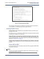
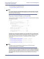
Connecting through the Web Management Interface . . . . . . . . . . . . . . . . . . . . . . . . 3-34
Accessing the Command Line Interface . . . . . . . . . . . . . . . . . . . . . . . . . . . . . . . . . . 3-34
Configuring the Router . . . . . . . . . . . . . . . . . . . . . . . . . . . . . . . . . . . . . . . . . . . . . . . . . . . . 3-40
Configuration Tables . . . . . . . . . . . . . . . . . . . . . . . . . . . . . . . . . . . . . . . . . . . . . . . . . 3-41
Configuring PPP with IP Routing . . . . . . . . . . . . . . . . . . . . . . . . . . . . . . . . . . . . . . . 3-42
Configuring PPP with IPX Routing . . . . . . . . . . . . . . . . . . . . . . . . . . . . . . . . . . . . . . 3-43
Configuring PPP with Bridging . . . . . . . . . . . . . . . . . . . . . . . . . . . . . . . . . . . . . . . . . 3-45
Configuring RFC 1483 / RFC 1490 with IP Routing . . . . . . . . . . . . . . . . . . . . . . . . . 3-46
Configuring RFC 1483 / RFC 1490 with IPX Routing . . . . . . . . . . . . . . . . . . . . . . . . 3-48
Configuring RFC 1483 / RFC 1490 with Bridging . . . . . . . . . . . . . . . . . . . . . . . . . . 3-49
Configuring RFC 1483MER / RFC 1490MER with IP Routing . . . . . . . . . . . . . . . . . 3-50
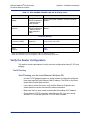
Verify the Router Configuration . . . . . . . . . . . . . . . . . . . . . . . . . . . . . . . . . . . . . . . . . . . . . 3-51
Test IP Routing . . . . . . . . . . . . . . . . . . . . . . . . . . . . . . . . . . . . . . . . . . . . . . . . . . . . . 3-51
Test Bridging to a Remote Destination . . . . . . . . . . . . . . . . . . . . . . . . . . . . . . . . . . . 3-52
Test IPX Routing . . . . . . . . . . . . . . . . . . . . . . . . . . . . . . . . . . . . . . . . . . . . . . . . . . . . 3-52
4 System Management . . . . . . . . . . . . . . . . . . . . . . . . . . . . . . . . . . . . . . . . . . . . . . 4-1
DHCP (Dynamic Host Configuration Protocol) . . . . . . . . . . . . . . . . . . . . . . . . . . . . . . . . . . 4-2
DHCP Address Allocation . . . . . . . . . . . . . . . . . . . . . . . . . . . . . . . . . . . . . . . . . . . . . . 4-2
DHCP Client Requests . . . . . . . . . . . . . . . . . . . . . . . . . . . . . . . . . . . . . . . . . . . . . . . . 4-3
DHCP Administration and Configuration. . . . . . . . . . . . . . . . . . . . . . . . . . . . . . . . . . . 4-3
Manipulating Subnetworks and Explicit Client Leases . . . . . . . . . . . . . . . . . . . . . . . . 4-4
Setting Option Values . . . . . . . . . . . . . . . . . . . . . . . . . . . . . . . . . . . . . . . . . . . . . . . . . 4-8
Managing BootP . . . . . . . . . . . . . . . . . . . . . . . . . . . . . . . . . . . . . . . . . . . . . . . . . . . . 4-10
Defining Option Types. . . . . . . . . . . . . . . . . . . . . . . . . . . . . . . . . . . . . . . . . . . . . . . . 4-12
DHCP Information File . . . . . . . . . . . . . . . . . . . . . . . . . . . . . . . . . . . . . . . . . . . . . . . 4-13
Clearing All DHCP Information . . . . . . . . . . . . . . . . . . . . . . . . . . . . . . . . . . . . . . . . . 4-14
6
Efficient Networks®
Efficient Networks® Router family
Technical Reference Guide
Table of Contents
Contents
BootP Service . . . . . . . . . . . . . . . . . . . . . . . . . . . . . . . . . . . . . . . . . . . . . . . . . . . . . . . . . . 4-15
BootP Concepts . . . . . . . . . . . . . . . . . . . . . . . . . . . . . . . . . . . . . . . . . . . . . . . . . . . . 4-15
BootP Service by the DHCP Server . . . . . . . . . . . . . . . . . . . . . . . . . . . . . . . . . . . . . 4-15
Relaying BootP Requests . . . . . . . . . . . . . . . . . . . . . . . . . . . . . . . . . . . . . . . . . . . . . 4-16
Network Address Translation (NAT) . . . . . . . . . . . . . . . . . . . . . . . . . . . . . . . . . . . . . . . . . 4-17
General NAT Rules . . . . . . . . . . . . . . . . . . . . . . . . . . . . . . . . . . . . . . . . . . . . . . . . . . 4-17
Masquerading . . . . . . . . . . . . . . . . . . . . . . . . . . . . . . . . . . . . . . . . . . . . . . . . . . . . . 4-18
Classic NAT . . . . . . . . . . . . . . . . . . . . . . . . . . . . . . . . . . . . . . . . . . . . . . . . . . . . . . . 4-23
Selective NAT . . . . . . . . . . . . . . . . . . . . . . . . . . . . . . . . . . . . . . . . . . . . . . . . . . . . . . 4-25
NetMeeting (H.323) with NAT . . . . . . . . . . . . . . . . . . . . . . . . . . . . . . . . . . . . . . . . . . 4-27
Key Enabled Features . . . . . . . . . . . . . . . . . . . . . . . . . . . . . . . . . . . . . . . . . . . . . . . . . . . . 4-29
Adding and Deleting Feature Keys . . . . . . . . . . . . . . . . . . . . . . . . . . . . . . . . . . . . . . 4-29
Listing the Installed Feature Keys . . . . . . . . . . . . . . . . . . . . . . . . . . . . . . . . . . . . . . . 4-32
Enabling and Disabling Features . . . . . . . . . . . . . . . . . . . . . . . . . . . . . . . . . . . . . . . 4-33
Feature Revocation. . . . . . . . . . . . . . . . . . . . . . . . . . . . . . . . . . . . . . . . . . . . . . . . . . 4-33
Spanning Tree . . . . . . . . . . . . . . . . . . . . . . . . . . . . . . . . . . . . . . . . . . . . . . . . . . . . . . . . . . 4-34
Boot Code Options. . . . . . . . . . . . . . . . . . . . . . . . . . . . . . . . . . . . . . . . . . . . . . . . . . . . . . . 4-34
What is the Boot Code? . . . . . . . . . . . . . . . . . . . . . . . . . . . . . . . . . . . . . . . . . . . . . . 4-34
Manual Boot Mode . . . . . . . . . . . . . . . . . . . . . . . . . . . . . . . . . . . . . . . . . . . . . . . . . . 4-36
IIdentifying Fatal Boot Failures . . . . . . . . . . . . . . . . . . . . . . . . . . . . . . . . . . . . . . . . . 4-40
Software Kernel Upgrades. . . . . . . . . . . . . . . . . . . . . . . . . . . . . . . . . . . . . . . . . . . . . . . . . 4-43
What is the Software Kernel? . . . . . . . . . . . . . . . . . . . . . . . . . . . . . . . . . . . . . . . . . . 4-43
Booting and Upgrading from the LAN . . . . . . . . . . . . . . . . . . . . . . . . . . . . . . . . . . . . 4-43
Upgrading from the WAN . . . . . . . . . . . . . . . . . . . . . . . . . . . . . . . . . . . . . . . . . . . . . 4-45
Quality of Service (QOS) . . . . . . . . . . . . . . . . . . . . . . . . . . . . . . . . . . . . . . . . . . . . . . . . . . 4-46
QoS Deployment Example . . . . . . . . . . . . . . . . . . . . . . . . . . . . . . . . . . . . . . . . . . . . 4-48
QoS Status . . . . . . . . . . . . . . . . . . . . . . . . . . . . . . . . . . . . . . . . . . . . . . . . . . . . . . . . 4-49
Policies . . . . . . . . . . . . . . . . . . . . . . . . . . . . . . . . . . . . . . . . . . . . . . . . . . . . . . . . . . . 4-50
Misc. Administrative Functions . . . . . . . . . . . . . . . . . . . . . . . . . . . . . . . . . . . . . . . . . . . . . 4-54
Setting the System Time and Date . . . . . . . . . . . . . . . . . . . . . . . . . . . . . . . . . . . . . . 4-54
5 System Security . . . . . . . . . . . . . . . . . . . . . . . . . . . . . . . . . . . . . . . . . . . . . . . . . . 5-1
User Authentication . . . . . . . . . . . . . . . . . . . . . . . . . . . . . . . . . . . . . . . . . . . . . . . . . . . . . . . 5-2
User Account Information . . . . . . . . . . . . . . . . . . . . . . . . . . . . . . . . . . . . . . . . . . . . . . 5-2
User Lookup . . . . . . . . . . . . . . . . . . . . . . . . . . . . . . . . . . . . . . . . . . . . . . . . . . . . . . . . 5-6
Creating a User Account . . . . . . . . . . . . . . . . . . . . . . . . . . . . . . . . . . . . . . . . . . . . . . . 5-7
Managing User Accounts . . . . . . . . . . . . . . . . . . . . . . . . . . . . . . . . . . . . . . . . . . . . . . 5-8
Radius . . . . . . . . . . . . . . . . . . . . . . . . . . . . . . . . . . . . . . . . . . . . . . . . . . . . . . . . . . . . . . . . 5-10
Efficient Networks®
7
Table of Contents
Efficient Networks® Router family
Technical Reference Guide
Contents
Client-Server Security . . . . . . . . . . . . . . . . . . . . . . . . . . . . . . . . . . . . . . . . . . . . . . . . 5-11
Radius Client Configuration Procedures . . . . . . . . . . . . . . . . . . . . . . . . . . . . . . . . . . 5-11
Radius Server Configuration . . . . . . . . . . . . . . . . . . . . . . . . . . . . . . . . . . . . . . . . . . . 5-13
Controlling Remote Management . . . . . . . . . . . . . . . . . . . . . . . . . . . . . . . . . . . . . . . . . . . 5-15
Disabling Remote Management . . . . . . . . . . . . . . . . . . . . . . . . . . . . . . . . . . . . . . . . 5-15
Re-enabling Remote Management . . . . . . . . . . . . . . . . . . . . . . . . . . . . . . . . . . . . . . 5-15
Validating Clients . . . . . . . . . . . . . . . . . . . . . . . . . . . . . . . . . . . . . . . . . . . . . . . . . . . 5-16
Restricting Remote Access . . . . . . . . . . . . . . . . . . . . . . . . . . . . . . . . . . . . . . . . . . . . 5-17
Changing the SNMP Community Name . . . . . . . . . . . . . . . . . . . . . . . . . . . . . . . . . . 5-17
Disabling WAN Management . . . . . . . . . . . . . . . . . . . . . . . . . . . . . . . . . . . . . . . . . . 5-18
Secure Mode Access . . . . . . . . . . . . . . . . . . . . . . . . . . . . . . . . . . . . . . . . . . . . . . . . . . . . . 5-18
Trusted and Untrusted Interfaces . . . . . . . . . . . . . . . . . . . . . . . . . . . . . . . . . . . . . . . 5-18
Secure Mode Management. . . . . . . . . . . . . . . . . . . . . . . . . . . . . . . . . . . . . . . . . . . . 5-18
PAP/CHAP Security Authentication . . . . . . . . . . . . . . . . . . . . . . . . . . . . . . . . . . . . . . . . . . 5-20
Authentication Process . . . . . . . . . . . . . . . . . . . . . . . . . . . . . . . . . . . . . . . . . . . . . . . 5-20
Authentication Passwords. . . . . . . . . . . . . . . . . . . . . . . . . . . . . . . . . . . . . . . . . . . . . 5-22
Authentication Levels . . . . . . . . . . . . . . . . . . . . . . . . . . . . . . . . . . . . . . . . . . . . . . . . 5-23
IP Filtering . . . . . . . . . . . . . . . . . . . . . . . . . . . . . . . . . . . . . . . . . . . . . . . . . . . . . . . . . . . . . 5-23
Filters and Interfaces. . . . . . . . . . . . . . . . . . . . . . . . . . . . . . . . . . . . . . . . . . . . . . . . . 5-23
Filter Actions . . . . . . . . . . . . . . . . . . . . . . . . . . . . . . . . . . . . . . . . . . . . . . . . . . . . . . . 5-25
IP Filter Commands . . . . . . . . . . . . . . . . . . . . . . . . . . . . . . . . . . . . . . . . . . . . . . . . . 5-25
ICMP Redirect. . . . . . . . . . . . . . . . . . . . . . . . . . . . . . . . . . . . . . . . . . . . . . . . . . . . . . 5-25
Filter Examples . . . . . . . . . . . . . . . . . . . . . . . . . . . . . . . . . . . . . . . . . . . . . . . . . . . . . 5-26
Built-in Firewall Filters . . . . . . . . . . . . . . . . . . . . . . . . . . . . . . . . . . . . . . . . . . . . . . . . 5-27
Stateful Firewall . . . . . . . . . . . . . . . . . . . . . . . . . . . . . . . . . . . . . . . . . . . . . . . . . . . . . . . . . 5-34
Firewall Rules . . . . . . . . . . . . . . . . . . . . . . . . . . . . . . . . . . . . . . . . . . . . . . . . . . . . . . 5-34
Firewall Status. . . . . . . . . . . . . . . . . . . . . . . . . . . . . . . . . . . . . . . . . . . . . . . . . . . . . . 5-41
Viewing Dropped Packets . . . . . . . . . . . . . . . . . . . . . . . . . . . . . . . . . . . . . . . . . . . . . 5-41
Message Logging . . . . . . . . . . . . . . . . . . . . . . . . . . . . . . . . . . . . . . . . . . . . . . . . . . . 5-42
Stateful Firewall and IPSec . . . . . . . . . . . . . . . . . . . . . . . . . . . . . . . . . . . . . . . . . . . . 5-42
Denial of Service Attacks . . . . . . . . . . . . . . . . . . . . . . . . . . . . . . . . . . . . . . . . . . . . . 5-42
Encryption . . . . . . . . . . . . . . . . . . . . . . . . . . . . . . . . . . . . . . . . . . . . . . . . . . . . . . . . . . . . . 5-46
PPP DES (RFC 1969) Encryption . . . . . . . . . . . . . . . . . . . . . . . . . . . . . . . . . . . . . . . 5-46
Diffie-Hellman Encryption . . . . . . . . . . . . . . . . . . . . . . . . . . . . . . . . . . . . . . . . . . . . . 5-47
IPSec (Internet Protocol Security) . . . . . . . . . . . . . . . . . . . . . . . . . . . . . . . . . . . . . . . . . . . 5-50
Transport and Tunnel Encapsulation Modes . . . . . . . . . . . . . . . . . . . . . . . . . . . . . . 5-50
ESP and AH Security Protocols . . . . . . . . . . . . . . . . . . . . . . . . . . . . . . . . . . . . . . . . 5-51
IKE Management . . . . . . . . . . . . . . . . . . . . . . . . . . . . . . . . . . . . . . . . . . . . . . . . . . . 5-52
8
Efficient Networks®
Efficient Networks® Router family
Technical Reference Guide
Table of Contents
Contents
Main Mode and Aggressive Mode. . . . . . . . . . . . . . . . . . . . . . . . . . . . . . . . . . . . . . . 5-54
Additional IKE Settings . . . . . . . . . . . . . . . . . . . . . . . . . . . . . . . . . . . . . . . . . . . . . . . 5-55
Security Associations (SAs) . . . . . . . . . . . . . . . . . . . . . . . . . . . . . . . . . . . . . . . . . . . 5-55
IKE Commands . . . . . . . . . . . . . . . . . . . . . . . . . . . . . . . . . . . . . . . . . . . . . . . . . . . . . . . . . 5-56
IKE Peer Commands . . . . . . . . . . . . . . . . . . . . . . . . . . . . . . . . . . . . . . . . . . . . . . . . 5-56
IKE Proposal Commands . . . . . . . . . . . . . . . . . . . . . . . . . . . . . . . . . . . . . . . . . . . . . 5-58
IKE IPSec Proposal Commands . . . . . . . . . . . . . . . . . . . . . . . . . . . . . . . . . . . . . . . . 5-58
IKE IPSec Policy Commands . . . . . . . . . . . . . . . . . . . . . . . . . . . . . . . . . . . . . . . . . . 5-61
IKE Configuration Examples . . . . . . . . . . . . . . . . . . . . . . . . . . . . . . . . . . . . . . . . . . . 5-62
IPSec Commands . . . . . . . . . . . . . . . . . . . . . . . . . . . . . . . . . . . . . . . . . . . . . . . . . . . . . . . 5-68
SSH . . . . . . . . . . . . . . . . . . . . . . . . . . . . . . . . . . . . . . . . . . . . . . . . . . . . . . . . . . . . . . . . . 5-70
SSH Protocol. . . . . . . . . . . . . . . . . . . . . . . . . . . . . . . . . . . . . . . . . . . . . . . . . . . . . . . 5-70
Key Exchange . . . . . . . . . . . . . . . . . . . . . . . . . . . . . . . . . . . . . . . . . . . . . . . . . . . . . . 5-72
Managing SSH . . . . . . . . . . . . . . . . . . . . . . . . . . . . . . . . . . . . . . . . . . . . . . . . . . . . . 5-72
Bridge Filtering. . . . . . . . . . . . . . . . . . . . . . . . . . . . . . . . . . . . . . . . . . . . . . . . . . . . . . . . . . 5-75
Configure Bridge Filtering . . . . . . . . . . . . . . . . . . . . . . . . . . . . . . . . . . . . . . . . . . . . . 5-76
6 Connection Management. . . . . . . . . . . . . . . . . . . . . . . . . . . . . . . . . . . . . . . . . . . 6-1
IP Subnets . . . . . . . . . . . . . . . . . . . . . . . . . . . . . . . . . . . . . . . . . . . . . . . . . . . . . . . . . . . . . . 6-1
Logical Interface Commands . . . . . . . . . . . . . . . . . . . . . . . . . . . . . . . . . . . . . . . . . . . 6-1
Stopping and Starting an Interface . . . . . . . . . . . . . . . . . . . . . . . . . . . . . . . . . . . . . . . 6-1
Interface Routing and Filtering . . . . . . . . . . . . . . . . . . . . . . . . . . . . . . . . . . . . . . . . . . 6-2
Virtual Routing Tables . . . . . . . . . . . . . . . . . . . . . . . . . . . . . . . . . . . . . . . . . . . . . . . . . . . . . 6-2
Procedures . . . . . . . . . . . . . . . . . . . . . . . . . . . . . . . . . . . . . . . . . . . . . . . . . . . . . . . . . 6-3
RIP Controls. . . . . . . . . . . . . . . . . . . . . . . . . . . . . . . . . . . . . . . . . . . . . . . . . . . . . . . . . . . . . 6-4
Advertising the Local Site . . . . . . . . . . . . . . . . . . . . . . . . . . . . . . . . . . . . . . . . . . . . . . 6-5
Changing the Multicast Address for RIP-2 Packets . . . . . . . . . . . . . . . . . . . . . . . . . . 6-5
ARP . . . . . . . . . . . . . . . . . . . . . . . . . . . . . . . . . . . . . . . . . . . . . . . . . . . . . . . . . . . . . . . . . . 6-6
Multicast Forwarding Controls . . . . . . . . . . . . . . . . . . . . . . . . . . . . . . . . . . . . . . . . . . . . . . . 6-6
Dial Backup . . . . . . . . . . . . . . . . . . . . . . . . . . . . . . . . . . . . . . . . . . . . . . . . . . . . . . . . . . . . . 6-7
Dial Backup with a Tunnel. . . . . . . . . . . . . . . . . . . . . . . . . . . . . . . . . . . . . . . . . . . . . . 6-7
Configuring Dial Backup . . . . . . . . . . . . . . . . . . . . . . . . . . . . . . . . . . . . . . . . . . . . . . . 6-8
Specifying the Dialup Parameters. . . . . . . . . . . . . . . . . . . . . . . . . . . . . . . . . . . . . . . . 6-9
Setting DSL Link Conditions . . . . . . . . . . . . . . . . . . . . . . . . . . . . . . . . . . . . . . . . . . . 6-11
Specifying Modem Parameters . . . . . . . . . . . . . . . . . . . . . . . . . . . . . . . . . . . . . . . . . 6-14
Disabling and Re-Enabling Dial Backup . . . . . . . . . . . . . . . . . . . . . . . . . . . . . . . . . . 6-15
VRRP Backup . . . . . . . . . . . . . . . . . . . . . . . . . . . . . . . . . . . . . . . . . . . . . . . . . . . . . . . . . . 6-16
VRRP Configuration . . . . . . . . . . . . . . . . . . . . . . . . . . . . . . . . . . . . . . . . . . . . . . . . . 6-16
Efficient Networks®
9
Table of Contents
Efficient Networks® Router family
Technical Reference Guide
Contents
Sample VRRP Configuration. . . . . . . . . . . . . . . . . . . . . . . . . . . . . . . . . . . . . . . . . . . 6-23
L2TP Tunneling - Virtual Dial-Up . . . . . . . . . . . . . . . . . . . . . . . . . . . . . . . . . . . . . . . . . . . . 6-26
Advantages of Tunneling . . . . . . . . . . . . . . . . . . . . . . . . . . . . . . . . . . . . . . . . . . . . . 6-26
L2TP Concepts . . . . . . . . . . . . . . . . . . . . . . . . . . . . . . . . . . . . . . . . . . . . . . . . . . . . . 6-27
Configuration. . . . . . . . . . . . . . . . . . . . . . . . . . . . . . . . . . . . . . . . . . . . . . . . . . . . . . . 6-29
Configuration Commands . . . . . . . . . . . . . . . . . . . . . . . . . . . . . . . . . . . . . . . . . . . . 6-30
Sample Configurations . . . . . . . . . . . . . . . . . . . . . . . . . . . . . . . . . . . . . . . . . . . . . . . 6-31
PPPoE (PPP over Ethernet) . . . . . . . . . . . . . . . . . . . . . . . . . . . . . . . . . . . . . . . . . . . . . . . 6-41
Configuring for PPPoE . . . . . . . . . . . . . . . . . . . . . . . . . . . . . . . . . . . . . . . . . . . . . . . 6-41
PPPoE Client . . . . . . . . . . . . . . . . . . . . . . . . . . . . . . . . . . . . . . . . . . . . . . . . . . . . . . 6-42
Sample PPPoE Configuration Script. . . . . . . . . . . . . . . . . . . . . . . . . . . . . . . . . . . . . 6-43
Managing PPPoE Sessions . . . . . . . . . . . . . . . . . . . . . . . . . . . . . . . . . . . . . . . . . . . 6-45
VPN . . . . . . . . . . . . . . . . . . . . . . . . . . . . . . . . . . . . . . . . . . . . . . . . . . . . . . . . . . . . . . . . . 6-46
Physical (Layer-1) VPNs . . . . . . . . . . . . . . . . . . . . . . . . . . . . . . . . . . . . . . . . . . . . . . 6-46
Transport (Layer-2) VPNs . . . . . . . . . . . . . . . . . . . . . . . . . . . . . . . . . . . . . . . . . . . . . 6-47
Network (Layer-3) VPNs . . . . . . . . . . . . . . . . . . . . . . . . . . . . . . . . . . . . . . . . . . . . . . 6-48
Technology Standards . . . . . . . . . . . . . . . . . . . . . . . . . . . . . . . . . . . . . . . . . . . . . . . 6-49
Tunnel Server . . . . . . . . . . . . . . . . . . . . . . . . . . . . . . . . . . . . . . . . . . . . . . . . . . . . . . 6-50
LAN-based Tunnel Client . . . . . . . . . . . . . . . . . . . . . . . . . . . . . . . . . . . . . . . . . . . . . 6-50
Workstation-based Tunnel Client . . . . . . . . . . . . . . . . . . . . . . . . . . . . . . . . . . . . . . . 6-50
Service Provider-based VPNs. . . . . . . . . . . . . . . . . . . . . . . . . . . . . . . . . . . . . . . . . . 6-51
Workstation Client to LAN Server . . . . . . . . . . . . . . . . . . . . . . . . . . . . . . . . . . . . . . . 6-52
LAN client to LAN server. . . . . . . . . . . . . . . . . . . . . . . . . . . . . . . . . . . . . . . . . . . . . . 6-52
Secure VPN Option . . . . . . . . . . . . . . . . . . . . . . . . . . . . . . . . . . . . . . . . . . . . . . . . . 6-53
VPN with IP Filtering and MS Networking. . . . . . . . . . . . . . . . . . . . . . . . . . . . . . . . . 6-61
7 Monitoring System Performance . . . . . . . . . . . . . . . . . . . . . . . . . . . . . . . . . . . . 7-1
Syslog Client . . . . . . . . . . . . . . . . . . . . . . . . . . . . . . . . . . . . . . . . . . . . . . . . . . . . . . . . . . . . 7-1
SNMP. . . . . . . . . . . . . . . . . . . . . . . . . . . . . . . . . . . . . . . . . . . . . . . . . . . . . . . . . . . . . . . . . . 7-2
MIBs . . . . . . . . . . . . . . . . . . . . . . . . . . . . . . . . . . . . . . . . . . . . . . . . . . . . . . . . . . . . . 7-2
Trap Generation . . . . . . . . . . . . . . . . . . . . . . . . . . . . . . . . . . . . . . . . . . . . . . . . . . . . . 7-3
Configuring SNMP . . . . . . . . . . . . . . . . . . . . . . . . . . . . . . . . . . . . . . . . . . . . . . . . . . . 7-4
Troubleshooting . . . . . . . . . . . . . . . . . . . . . . . . . . . . . . . . . . . . . . . . . . . . . . . . . . . . . . . . . . 7-6
Diagnostic Tools . . . . . . . . . . . . . . . . . . . . . . . . . . . . . . . . . . . . . . . . . . . . . . . . . . . . . 7-6
L2TP Tunnel Troubleshooting. . . . . . . . . . . . . . . . . . . . . . . . . . . . . . . . . . . . . . . . . . 7-15
8 WEB Management Interface . . . . . . . . . . . . . . . . . . . . . . . . . . . . . . . . . . . . . . . . 8-1
Organization. . . . . . . . . . . . . . . . . . . . . . . . . . . . . . . . . . . . . . . . . . . . . . . . . . . . . . . . . . . . . 8-1
10
Efficient Networks®
Efficient Networks® Router family
Technical Reference Guide
Table of Contents
Contents
Accessibility . . . . . . . . . . . . . . . . . . . . . . . . . . . . . . . . . . . . . . . . . . . . . . . . . . . . . . . . . . . . . 8-1
User Interaction . . . . . . . . . . . . . . . . . . . . . . . . . . . . . . . . . . . . . . . . . . . . . . . . . . . . . . . . . . 8-1
Router Information Page . . . . . . . . . . . . . . . . . . . . . . . . . . . . . . . . . . . . . . . . . . . . . . . . . . . 8-3
Easy Setup. . . . . . . . . . . . . . . . . . . . . . . . . . . . . . . . . . . . . . . . . . . . . . . . . . . . . . . . . . . . . . 8-4
Protocol Selection Page . . . . . . . . . . . . . . . . . . . . . . . . . . . . . . . . . . . . . . . . . . . . . . . 8-4
Point-to-Point Protocol over ATM . . . . . . . . . . . . . . . . . . . . . . . . . . . . . . . . . . . . . . . . 8-6
Point-to-Point Protocol over Ethernet over PPPoA . . . . . . . . . . . . . . . . . . . . . . . . . . . 8-7
Point-to-Point over Ethernet over RFC 1483 . . . . . . . . . . . . . . . . . . . . . . . . . . . . . . . 8-8
RFC 1483 Networking. . . . . . . . . . . . . . . . . . . . . . . . . . . . . . . . . . . . . . . . . . . . . . . . 8-10
RFC 1483 MAC Encapsulated Routing. . . . . . . . . . . . . . . . . . . . . . . . . . . . . . . . . . . 8-12
Dynamic Host Configuration Protocol . . . . . . . . . . . . . . . . . . . . . . . . . . . . . . . . . . . . 8-14
Local Area Network Configuration . . . . . . . . . . . . . . . . . . . . . . . . . . . . . . . . . . . . . . 8-16
User Management . . . . . . . . . . . . . . . . . . . . . . . . . . . . . . . . . . . . . . . . . . . . . . . . . . . . . . . 8-17
User Management Main Page . . . . . . . . . . . . . . . . . . . . . . . . . . . . . . . . . . . . . . . . . 8-17
User Lookup Configuration . . . . . . . . . . . . . . . . . . . . . . . . . . . . . . . . . . . . . . . . . . . . 8-22
Secure Mode Configuration . . . . . . . . . . . . . . . . . . . . . . . . . . . . . . . . . . . . . . . . . . . 8-23
Change Password . . . . . . . . . . . . . . . . . . . . . . . . . . . . . . . . . . . . . . . . . . . . . . . . . . . . . . . 8-24
Access Control Form . . . . . . . . . . . . . . . . . . . . . . . . . . . . . . . . . . . . . . . . . . . . . . . . . . . . . 8-25
Examples . . . . . . . . . . . . . . . . . . . . . . . . . . . . . . . . . . . . . . . . . . . . . . . . . . . . . . . . . 8-26
Feature Activation . . . . . . . . . . . . . . . . . . . . . . . . . . . . . . . . . . . . . . . . . . . . . . . . . . . . . . . 8-26
Key Enabled Feature List Page . . . . . . . . . . . . . . . . . . . . . . . . . . . . . . . . . . . . . . . . 8-27
Add Feature Page . . . . . . . . . . . . . . . . . . . . . . . . . . . . . . . . . . . . . . . . . . . . . . . . . . . 8-28
Delete Feature Page . . . . . . . . . . . . . . . . . . . . . . . . . . . . . . . . . . . . . . . . . . . . . . . . . 8-29
Update Feature Page . . . . . . . . . . . . . . . . . . . . . . . . . . . . . . . . . . . . . . . . . . . . . . . . 8-30
Feature Enabled/Disable Page . . . . . . . . . . . . . . . . . . . . . . . . . . . . . . . . . . . . . . . . . 8-31
Revoke Feature Page . . . . . . . . . . . . . . . . . . . . . . . . . . . . . . . . . . . . . . . . . . . . . . . . 8-32
Unrevoke Feature Page . . . . . . . . . . . . . . . . . . . . . . . . . . . . . . . . . . . . . . . . . . . . . . 8-33
Router Clock Page . . . . . . . . . . . . . . . . . . . . . . . . . . . . . . . . . . . . . . . . . . . . . . . . . . . . . . . 8-34
DCHP Configuration . . . . . . . . . . . . . . . . . . . . . . . . . . . . . . . . . . . . . . . . . . . . . . . . . . . . . 8-35
NAT . . . . . . . . . . . . . . . . . . . . . . . . . . . . . . . . . . . . . . . . . . . . . . . . . . . . . . . . . . . . . . . . . 8-38
Outbound NAT Setting . . . . . . . . . . . . . . . . . . . . . . . . . . . . . . . . . . . . . . . . . . . . . . . 8-38
Inbound NAT Setting. . . . . . . . . . . . . . . . . . . . . . . . . . . . . . . . . . . . . . . . . . . . . . . . . 8-39
SNMP. . . . . . . . . . . . . . . . . . . . . . . . . . . . . . . . . . . . . . . . . . . . . . . . . . . . . . . . . . . . . . . . . 8-41
SNMP Configuration Page . . . . . . . . . . . . . . . . . . . . . . . . . . . . . . . . . . . . . . . . . . . . 8-41
SNMP IP Filter Page . . . . . . . . . . . . . . . . . . . . . . . . . . . . . . . . . . . . . . . . . . . . . . . . . 8-43
SNMP Password Page . . . . . . . . . . . . . . . . . . . . . . . . . . . . . . . . . . . . . . . . . . . . . . . 8-44
SSH . . . . . . . . . . . . . . . . . . . . . . . . . . . . . . . . . . . . . . . . . . . . . . . . . . . . . . . . . . . . . . . . . 8-45
Efficient Networks®
11
Table of Contents
Efficient Networks® Router family
Technical Reference Guide
Contents
Secure Shell (SSH) Configuration List Page. . . . . . . . . . . . . . . . . . . . . . . . . . . . . . . 8-45
Secure Shell Configuration page . . . . . . . . . . . . . . . . . . . . . . . . . . . . . . . . . . . . . . . 8-46
Firewall Scripts. . . . . . . . . . . . . . . . . . . . . . . . . . . . . . . . . . . . . . . . . . . . . . . . . . . . . . . . . . 8-50
QoS . . . . . . . . . . . . . . . . . . . . . . . . . . . . . . . . . . . . . . . . . . . . . . . . . . . . . . . . . . . . . . . . . 8-52
QoS Configuration Page . . . . . . . . . . . . . . . . . . . . . . . . . . . . . . . . . . . . . . . . . . . . . . 8-52
QoS Policy Configuration page . . . . . . . . . . . . . . . . . . . . . . . . . . . . . . . . . . . . . . . . . 8-54
Stateful Firewall . . . . . . . . . . . . . . . . . . . . . . . . . . . . . . . . . . . . . . . . . . . . . . . . . . . . . . . . . 8-60
Stateful Firewall Configuration Page. . . . . . . . . . . . . . . . . . . . . . . . . . . . . . . . . . . . . 8-60
Dropped Packet Page . . . . . . . . . . . . . . . . . . . . . . . . . . . . . . . . . . . . . . . . . . . . . . . . 8-62
Firewall Rule Configuration page . . . . . . . . . . . . . . . . . . . . . . . . . . . . . . . . . . . . . . . 8-63
Dial Backup . . . . . . . . . . . . . . . . . . . . . . . . . . . . . . . . . . . . . . . . . . . . . . . . . . . . . . . . . . . . 8-68
Command Line Interface . . . . . . . . . . . . . . . . . . . . . . . . . . . . . . . . . . . . . . . . . . . . . . . . . . 8-71
Web Management Interface Privileges . . . . . . . . . . . . . . . . . . . . . . . . . . . . . . . . . . . . . . . . . . 8-72
12
Efficient Networks®
Efficient Networks® Router family
Technical Reference Guide
Chapter 1: Introduction
CHAPTER 1
CHAPTER 1
INTRODUCTION
This manual contains information on the advanced functions, features, and
management of your router. This manual is intended for small and home office users,
remote office users, and other networking professionals who are installing and
maintaining bridged and routed networks.
It assumes that you have read the User Reference Guide that came with the router
and have installed the router as described in that guide. Configuration of network
connections, bridging, routing, and security features are essentially the same for all
DSL routers, unless otherwise noted.
How This Manual is Organized
This manual is organized in 8 chapters.
•
Chapter 1, Introduction - Provides an overview of the scope and layout of the
manual as well as conventions and terminology used throughout the manual.
•
Chapter 2, Product Overview - Provides an overview of the products and
features supported within this document.
•
Chapter 3, Installation and Setup - Provides the planning information,
configuration procedures, and verification tools to perform the initial setup of
the router.
•
Chapter 4, System Management - Provides topical and management
information on a variety of system features and functions.
•
Chapter 5, System Security - Discusses the security features of the router.
•
Chapter 6, Connection Management - Provides information for managing the
various interfaces of the router.
•
Chapter 7, Monitoring System Performance - Provides information on the
tools available to monitor the router’s operation as well as troubleshooting
information.
•
Chapter 8, WEB Management Interface - Provides information on the Web
Management Interface.
Efficient Networks®
Page 1-1
Efficient Networks® Router family
Technical Reference Guide
Chapter 1: Introduction
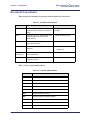
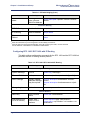
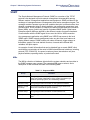
Document Conventions
Table explains the standard conventions used throughout this document.
Table 1-1: Document Conventions
Convention
Description
Example
Boldface
Buttons, check-boxes, or other items that
represent selection made from screens or
menus.
Click Apply to affect the
changes
Italics
Keywords, new words, documentation titles,
listed parameters, and other terms of
special interest.
...saves the dhcp.cfg file.
Code
Command, parameter, keyword, value, or
other user-entered text.
set timezone
>
Menu item. Indented > represent sub-menu
selections.
> System
> Password
|
(vertical bar)
Delineates valid options of which one may
be entered/selected.
enable | disable
<variable>
Indicates a field that requires information
supplied by the user.
user add user <username>
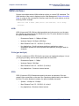
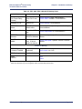
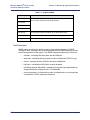
Table 1-2 lists common abbreviations.
Table 1-2: Common Abbreviations
Page 1-2
AAL
ATM Adaptation Layer
AAL2
ATM Adaptation Layer 2
AAL5
ATM Adaptation Layer 5
ADPCM
Adaptive Differential Pulse Code Modulation
ADSL
Asymmetric Digital Subscriber Line
ARP
Address Resolution Protocol
ATE
ATM Terminating Equipment (SONET)
ATM
Asynchronous Transfer Mode
ATMF BLES
ATM Forum Broadband Loop Emulation Service
BCD
Binary Coded Decimal
Efficient Networks®
Efficient Networks® Router family
Technical Reference Guide
Chapter 1: Introduction
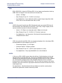
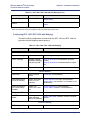
Table 1-2: Common Abbreviations
BER
Basic Encoding Rules or Bit Error Rate
B-HLI
Broadband High Layer Information
B-ICI
Broadband Intercarrier Interface
B-ISSI
Broadband Inter-Switching System Interface
B-LLI
Broadband Low Layer Information
BOM
Beginning of Message
BUS
Broadcast Unknown Server
CBR
Constant Bit Rate
CDV
Cell Delay Variation
CLI
Command Line Interface
CLP
Cell Loss Priority
CMISE
Common Management Information Service Element
CNM
Customer Network Management
CPCS
Common Part Convergence Sublayer
CPE
Customer Premises Equipment
CPI
Common Part Indicator
CRF(VC)
Virtual Channel Connection Related Function
CRF(VP)
Virtual Path Connection Related Function
CRS
Cell Relay Service
CS
Convergence Sublayer
EOM
End of Message
GUI
Graphical User Interface
HEC
Header Error Control
IETF
Internet Engineering Task Force
IPX
Internetwork Packet Exchange
LAN
Local Area Network
LCD
Loss of Cell Delineation
LOF
Loss of Frame (UNI Fault Management)
Efficient Networks®
Page 1-3
Efficient Networks® Router family
Technical Reference Guide
Chapter 1: Introduction
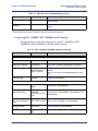
Table 1-2: Common Abbreviations
Page 1-4
LOP
Loss of Pointer (UNI Fault Management)
LOS
Loss of Signal (UNI Fault Management)
MAC
Media Access Control
NG-IAD
Next Generation - Integrated Access Device
NIU
Network Interface Unit
OAM
Operations and Management
OCD
Out-of-Cell Delineation
PCM
Pulse Code Modulation
PCR
Peak Cell Rate
POST
Power-On Self Test
POTS
Plain Old Telephone System
PTI
Payload Type Identifier
PVC
Permanent Virtual Connection
QoS
Quality of Service
RIP
Routing Information Protocol
SAAL
Signalling ATM Adaptation Layer
SCR
Sustainable Cell Rate
SDU
Service Data Unit
SIR
Sustained Information Rate
SNMP
Simple Network Management Protocol
SVC
Switched Virtual Connection
UME
UNI Management Entity
VBR
Variable Bit Rate
VC
Virtual Channel
VCC
Virtual Channel Connection
VCI
Virtual Channel Identifier
VCL
Virtual Channel Link
VP
Virtual Path
Efficient Networks®
Efficient Networks® Router family
Technical Reference Guide
Chapter 1: Introduction
Table 1-2: Common Abbreviations
VPCI
Virtual Path Connection Identifier
VPI
Virtual Path Identifier
WMI
Web Management Interface
Efficient Networks®
Page 1-5
Chapter 1: Introduction
Efficient Networks® Router family
Technical Reference Guide
This page intentionally left blank.
Page 1-6
Efficient Networks®
Efficient Networks® Router family
Technical Reference Guide
Chapter 2: Product Overview
CHAPTER 2
CHAPTER 2
PRODUCT OVERVIEW
This chapter provides background information applicable to the Efficient Networks
Router Family. These topics include:
•
WAN Interfaces
•
Virtual Connections
–
ATM
–
Routing and Bridging
•
System Interoperability
•
Protocol Conformance
•
Encapsulation Options
Efficient Networks®
Page 2-1
Chapter 2: Product Overview
Efficient Networks® Router family
Technical Reference Guide
WAN Interfaces
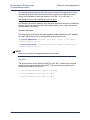
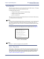
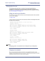
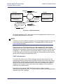
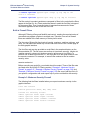
Routers are available whose WAN interfaces conform to various DSL standards. The
WAN interface of the router is displayed on the Web Management Router Information
Page or on the via the command line interface each time the router reboots, as in the
following SHDSL example:
Efficient 5950 G.SHDSL [ATM] Router (120-5950-001) v6.0.0 Ready
Username:
ADSL
ADSL (Asymmetric DSL) Delivers high-speed data and voice service over the same
line. Speeds are determined by the distance from the CO; as the distance increases,
the speed available decreases.
•
Downstream Speed - 1.5 Mbps to 8 Mbps
•
Upstream Speed - 64 Kbps to 800 Kbps
•
Max. Distance From CO - 18,000 ft. (3.4 miles)*
•
Key Applications - Small businesses and home applications, where
downstream speeds are more important than upstream (surfing the web, for
example)
G.Lite (gee’-dot-light)
G.Lite is a variation on ADSL; DSL that the end user can install and configure. It is not
yet fully plug and play, and has lower speeds than full-rate ADSL.
•
Downstream Speed - 1.5 Mbps
•
Upstream Speed - 384 Kbps
•
Max. Distance From CO - 18,000 ft. (3.4 miles)*
•
Key Applications - Consumer Internet access
SDSL
SDSL (Symmetric DSL) Downstream speed is the same as upstream. Does not
support voice connections on the same line. Speeds are determined by the distance
from the CO; as the distance increases, the speed available decreases.
Page 2-2
•
Speeds - 160 Kbps to 2.3 Mbps
•
Max. Distance From CO - 22,000 ft. (4.1 miles)*
•
Key Applications - Business Internet access
Efficient Networks®
Efficient Networks® Router family
Technical Reference Guide
Chapter 2: Product Overview
IDSL
IDSL (ISDN DSL) A hybrid of ISDN and DSL; it’s an always on alternative to dial up
ISDN. Does not support voice connections on the same line.
•
Speed - 144 Kbps
•
Max. Distance From CO - 35,000 ft. (6.6 miles)*
•
Key Applications - As an alternate solution: it has a longer range than other
DSLs, and is more affordable than dial-up ISDN.
SHDSL
SHDSL (Symmetric high-bit-rate DSL) Standards-based symmetrical DSL that will
become widely used, particularly for business. It uses only a single copper pair but
can be doubled to two pair for twice the bandwidth.
•
Speed - 2.31 Mbps over single pair and 4.6 Mbps over two pair
•
Max. Distance From CO - 20,000 ft. (3.78 miles)* and more
•
Key Applications - low frequencies. Small and mid-sized business and
enterprise branch offices.
VDSL
VDSL (Very high-bit-rate DSL) Still in an experimental phase, this is the fastest DSL,
but deliverable over short distance from the CO.
•
Downstream Speed - 13 to 52 Mbps
•
Upstream Speed - 16 Mbps upstream
•
Max. Distance From CO - 4,000 ft. (three quarters of a mile)*
•
Key Applications - Carry high-bandwidth over a short distance.
VoDSL
A Voice over DSL (VoDSL) router allows the delivery of both telephony (voice) and
data services over a single DSL line. It acts as an Integrated Access Device (IAD),
residing on the customer premises and connecting to a DSL circuit. As such, it serves
as a circuit/packet gateway and provides standard telephone service as well as
Internet service via an Ethernet connection. Thus, the user has access to toll-quality
telephone lines and continuous, high-speed Internet and remote LAN services over a
single copper loop.
Key Applications - Small businesses that can balance a need for several phone
extensions against their Internet connectivity needs.
Efficient Networks®
Page 2-3
Chapter 2: Product Overview
Efficient Networks® Router family
Technical Reference Guide
Virtual Connections
The router’s wide area network (WAN) interface uses Asynchronous Transfer Mode
(ATM) virtual connections (VCs) to transport data. The system provides unlimited VC
support.
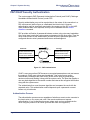
ATM
Asynchronous Transfer Mode (ATM) is a networking technology that provides support
for a wide variety of services and applications.
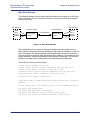
ATM is based on the transfer of fixed-length cells (53-byte) containing a header and
an information field. The header is used to route the cells through the ATM network
backbone. ATM defines the connections by two main parameters:
•
Virtual Path Identifier (VPI) - The VPI is an 8-bit field in the header of an ATM
cell.
•
Virtual Channel Identifier (VCI) - The VCI is a 16-bit field in the header of an
ATM cell.
These parameters, used together, provide information that identifies the cell’s
destination as it passes through ATM switches.
When there is no data to transfer, the ATM link (endpoint-to-endpoint) will send cells
across the link until data is present; at that point, the data is incorporated into the
stream of cells. When multiple VCs are needed simultaneously, the data is
multiplexed to share the link bandwidth.
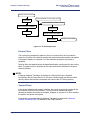
Routing and Bridging
The 5900 Series Business Gateway does not operate in an explicit bridging or routing
mode, but can operate as a bridge, as a router, or as both as defined by the
configuration of the specified protocol. The following sections describe routing and
bridging and how the two functions operate together.
Routing
Routing is the process that determines where data is sent. A router can route user
data from source to destination over different LAN and WAN links. Routing relies on
routing address tables to determine the best path for each packet to take.
The routes within a routing address table are established in two ways:
Page 2-4
•
You can enter specific static routes. For each route, you enter the address for
a remote destination with path details and a value for the perceived cost of
that route (path latency).
•
The routing tables can also be built dynamically; i.e., the location of remote
stations, hosts, and networks are updated from broadcast packet
information.
Efficient Networks®
Efficient Networks® Router family
Technical Reference Guide
Chapter 2: Product Overview
Routing offers advantages over bridging because:
•
It limits broadcasts to the local LAN segment.
•
It limits the protocols that are routed beyond the LAN segment.
•
Routed protocols allow networks to grow as large as needed.
•
Filters and firewalls can provide screens for improved security and managed
traffic flow.
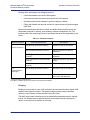
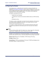
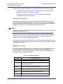
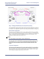
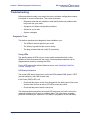
Numerous network protocols have evolved, and within certain protocol suites are
associated protocols for routing, error handling, network management, etc. The
following chart lists networking protocols and associated protocols supported by the
router.
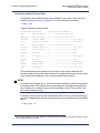
Table 2-1: Network Protocols
Network Protocol
IP
(Internet Protocol)
IPX
(Internet Packet
Exchange)
a
b
Associated Protocols
Description
RIP (Routing Information Protocol)
Maintains a map of the network
ARP (Address-Resolution Protocol)
Maps IP addresses to data-link
addresses
RARP (Reverse Address Resolution
Protocol)a
Maps data-link addresses to IP
addresses
ICMP (Internetwork Control Message
Protocol)
Diagnostic and error reporting/recovery
SNMP (Simple Network Management
Protocol)
Network management
RIP (Routing Information Protocol)b
Maintains a map of the network
SAP (Service Advertising Protocol)
Distributes information about service names and addresses
Used only during a network boot.
IPX-RIP is a different protocol from IP-RIP and it includes time delays.
Bridging
Bridging connects two or more LANs so that all devices share the same logical LAN
segment and network numbers. Transparent bridging allows locally connected
devices to send frames to all devices as if they were local.
The MAC layer header contains source and destination addresses used to transfer
frames. An address table is dynamically built and updated with the logical port a
device is connected to as frames are received.
Efficient Networks®
Page 2-5
Chapter 2: Product Overview
Efficient Networks® Router family
Technical Reference Guide
Bridging has these capabilities:
•
Allows protocols that cannot be routed (such as NETBIOS) to be forwarded.
•
Allows optimizing internetwork capacity by localizing traffic on LAN
segments.
•
Extends the physical reach of networks beyond the limits of each LAN
segment.
•
Bridge filtering may increase network security.
Our bridging support includes the IEEE 802.1D standard for LAN-to-LAN bridging and
the Spanning Tree Protocol for interoperability with other vendors’ bridge/routers.
Bridging is provided over PPP as well as adjacent LAN ports.
Bridge-Only Units
A series of bridge-only units is available, both upgradable and non-upgradable. An
upgradable bridge can be upgraded to a router; a non-upgradable bridge cannot.
These bridge-only units are pre-configured; no further configuration is required. The
unit comes up in bridge mode automatically.
Upgrading an upgradable bridge to become a router requires the addition of a
software option key. The software option key turns on the IP Routing feature.
Bridge Filtering
You can control the flow of packets through the router using bridge filters. The filters
can “deny” or “allow” packets to cross the network based on the content of the
packets. This feature lets you restrict or forward messages with a specified address,
protocol, or data content. Common uses are to prevent access to remote networks,
control unauthorized access to the local network, and limit unnecessary traffic.
For example, to restrict remote access for specific users, you could define bridge
filters using the local MAC address of each user to be restricted. Each bridge filter is
specified as a “deny” filter based on the MAC address and position of the address
within the packet. Deny filtering mode is then enabled to initiate bridge filtering. While
in deny mode, all packets containing one of the filtered MAC addresses are denied
bridging across the router.
Similarly, protocol filtering can be used to prevent a specific protocol from being
bridged. In this case, the protocol ID field in a packet is used to deny or allow a
packet. You can also restrict the bridging of specific broadcast packets.
For a further discussion of bridge filtering, see “Bridge Filtering” on page 5-75.
Page 2-6
Efficient Networks®
Efficient Networks® Router family
Technical Reference Guide
Chapter 2: Product Overview
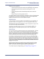
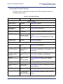
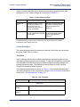
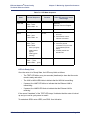
When to Use Routing or Bridging or Both
The following charts describe the operational characteristics of the router when you
enable routing, bridging, or both routing and bridging.
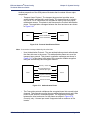
Table 2-2: Routing vs. Bridging Comparison
IP/IPX Routing On
Bridging to/from Remote Router Off
Data packets carried
IP (TCP, UDP), IPX
Operational characteristics
Basic IP, IPX connectivity
Typical usage
When only IP/IPX traffic is to be routed and all other traffic
is to be ignored. For IP, used for Internet access.
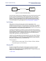
IP/IPX Routing On
Bridging to/from Remote Router On
Data packets carried
IP/IPX routed; all other packets bridged.
Operational characteristics
IP/IPX routing; allows other protocols, such as NetBEUI
(that can’t be routed), to be bridged.
Typical usage
When only IP/IPX traffic is to be routed but some non-routed protocol is required. Used for client/server configurations.
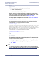
IP/IPX Routing Off
Bridging to/from Remote Router On
Data packets carried
All packets bridged.
Operational characteristics
Allows use of protocols that can’t be routed (such as NetBEUI).
Typical usage
Peer-to-peer bridging and when the remote end supports
only bridging.
How Routing and Bridging Work Together
The router follows these rules when operating as both a router and a bridge:
•
The router operates as a router for network protocols that are enabled for
routing (IP or IPX).
•
The router operates as a bridge for protocols that are not supported for
routing.
•
Routing takes precedence over bridging; i.e., when routing is active, the
router uses the packet’s protocol address information to route the packet.
•
If the protocol is not supported, then bridging uses the MAC address
information to forward the packet.
Efficient Networks®
Page 2-7
Efficient Networks® Router family
Technical Reference Guide
Chapter 2: Product Overview
Routing and Bridging Controls
The router can be configured to perform general routing and bridging while allowing
you to set specific controls.
•
One remote router can be designated as the outbound default bridging
destination. All outbound bridging traffic with an unknown destination is sent
to the default bridging destination.
•
Bridging can be enabled or disabled for specific remote routers.
•
Routing can be enabled or disabled for the entire router and for individual
remotes.
Operation of the router is influenced by routing and bridging controls and filters set
during router configuration as well as automatic spoofing and filtering performed by
the router. For example, general IP or IPX routing, and routing or bridging from
specific remote routers are controls set during the configuration process.
Spoofing and filtering, which minimize the number of packets that flow across the
WAN, are performed automatically by the router. For example, RIP routing packets
and certain NetBEUI packets are spoofed even if only bridging is enabled.
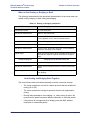
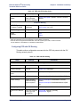
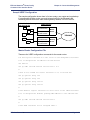
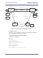
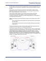
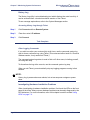
System Interoperability
The router uses industry-wide standards to ensure compatibility with routers and
equipment from other vendors. To inter-operate, the router supports standard
protocols on the physical level, data link level, and network level. For two systems to
communicate directly, they must use the same protocol at each level.
Level
Interoperability
Determined by
Physical
media
Hardware and electrical
signaling
Router Ethernet and modem hardware interfaces for copper wire or fiber cable
Data link
Packet transmission
method (frame type or
encapsulation method)
Router hardware and software kernel. Can be Ethernet, ATM, or Frame
Relay
Network
layer
Network protocol
Router configuration. Can be IP or
IPX
The data-link protocol level defines the transmission of data packets between two
systems over the LAN or WAN physical link. The frame type or encapsulation method
defines a way to run multiple network-level protocols over a single LAN or WAN link.
Most protocols do not support negotiable options, except for PPP.
The router supports both ATM (Asynchronous Transfer Mode) and Frame Relay
transmission. ATM transport uses fixed-length cells; Frame Relay transport uses
variable-length packets.
Page 2-8
Efficient Networks®
Efficient Networks® Router family
Technical Reference Guide
Chapter 2: Product Overview
The router supports the following WAN encapsulations:
•
PPP (VC multiplexing)
•
PPP (LLC multiplexing)
•
PPPoE (PPP over Ethernet)
•
RFC 1483 (for ATM)
•
RFC 1483 with MAC encapsulated routing (for ATM)
•
FRF8 (for ATM)
•
RFC 1490 (for Frame Relay)
•
RFC 1490 with MAC encapsulated routing (for Frame Relay)
•
The packet formats for these encapsulation methods are given in
“Encapsulation Options” on page 2-11.
Protocol Conformance
The router conforms to RFCs designed to address performance, authentication, and
multi-protocol encapsulation. The following RFCs are supported:
RFC 1058 Routing Information Protocol (RIP)
RFC 1144 Compressing TCP/IP headers (Van Jacobson)
RFC 1220 Bridging Control Protocol (BNCP)
RFC 1332 IP Control Protocol (IPCP)
RFC 1334 Password Authentication Protocol and Challenge Handshake Authentication Protocol (PAP/CHAP)
RFC 1389 RIP2
RFC 1483 Multiprotocol Encapsulation over ATM Adaptation Layer 5
RFC 1490 Multiprotocol Interconnect over Frame Relay
RFC 1542 DHCP Relay Agent
RFC 1552 Novell IPX Control Protocol (IPXCP)
RFC 1577 Classical IP and ARP over ATM
RFC 1631 Network Renumbering
RFC 1661 Point-to-Point Protocol (PPP)
RFC 1723 RIP Version 2
RFC 1769 Simple Network Time Protocol (SNTP)
RFC 1877 Automatic IP / DNS
RFC 1962 PPP Compression Control Protocol (CCP)
RFC 1969 PPP DES Encryption Protocol (ECP)
RFC 1973 PPP in Frame Relay
Efficient Networks®
Page 2-9
Chapter 2: Product Overview
Efficient Networks® Router family
Technical Reference Guide
RFC 1974 PPP Stac LZS Compression Protocol
RFC 1990 Multi-Link Protocol (MLP)
RFC 1994 User Authentication PAP / CHAP
RFC 2104 HMAC: Keyed-Hashing for Message Authentication
RFC 2131 Dynamic Host Configuration Protocol (DHCP)
RFC 2132 DHCP Client
RFC 2364 PPP over AAL5
RFC 2401 Security Architecture for the Internet Protocol
RFC 2402 IP Authentication Header
RFC 2403 The Use of HMAC-MD5-96 within ESP and AH
RFC 2404 The Use of HMAC-SHA-1-96 within ESP and AH
RFC 2405 The ESP DES-CBC Cipher Algorithm With Explicit IV
RFC 2406 IP Encapsulating Security Payload (ESP)
RFC 2407 The Internet IP Security Domain of Interpretation for ISAKMP
RFC 2408 Internet Security Association and Key Management Protocol (ISAKMP)
RFC 2409 The Internet Key Exchange (IKE)
RFC 2410 The NULL Encryption Algorithm and Its Use with IPSec
RFC 2412 The OAKLEY Key Determination Protocol
RFC 2419 PPP DES Encryption v2
RFC 2451 The ESP CBC-Mode Cipher Algorithms
IP Routing
IP routing support, in conformance with RFC 791, provides the ability to process TCP/
IP frames at the network layer for routing. IP routing support includes the Routing
Interface Protocol (RIP), in conformance with RFC 1058 (RIP v.1) and RFC 1723 (RIP
v.2).
IPX Routing
IPX routing conforms to the Novell® NetWare™ IPX Router Development Guide,
Version 1.10.
Page 2-10
Efficient Networks®
Efficient Networks® Router family
Technical Reference Guide
Chapter 2: Product Overview
Encapsulation Options
This section describes the packet format for each encapsulation option supported by
the router.
NOTE:
The same encapsulation method must be used by both ends of the connection (the
router and the DSLAM).
PPP
This protocol uses VC multiplexing, as defined in RFC 2364; it dedicates a virtual
circuit to PPP traffic only. (The other encapsulation method defined in RFC 2364, LLC
multiplexing, is described in the next section, PPPLLC.)
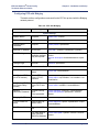
Each packet begins with a one- or two-byte protocol ID. Typical IDs are:
0xc021
LCP
0x8021
0x0021
0x002d
0x002f
0x8031
0x0031
IPCP
IP
Van Jacobson compressed TCP/IP
Van Jacobson uncompressed TCP/IP
Bridge NCP
Bridge Frame
NOTE:
With PPP over ATM, the address and control fields (i.e., FF03) are never present; this
also is the case for LCP packets.
PPPLLC
This protocol (LLC-multiplexed) allows PPP traffic to be carried simultaneously with
other traffic on a single virtual circuit (as opposed to the PPP method of encapsulation
- VC multiplexing - which dedicates a virtual circuit to PPP traffic only).
Each PPP packet is prepended with the sequence 0xFEFE03CF. Thus, an LLC
packet has the format: 0xFEFE03CF 0xC021.
Efficient Networks®
Page 2-11
Chapter 2: Product Overview
Efficient Networks® Router family
Technical Reference Guide
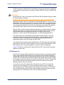
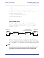
RFC 1483 or RFC 1490
Bridging
User data packets are prepended by the sequence 0xAAAA0300 0x80c20007 0x0000
followed by the Ethernet frame containing the packet.
802.1D Spanning Tree packets are prepended with the header 0xAAAA0300
0x80C2000E.
Routing
IP packets are prepended with the header 0xAAAA0300 0x00000800.
IPX packets are prepended with the header 0xAAAA0300 0x00008137.
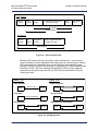
MAC Encapsulated Routing: RFC 1483MER (ATM)
or RFC 1490MER (Frame Relay)
MER encapsulation allows IP packets to be carried as bridged frames, but does not
prevent bridged frames from being sent as well, in their normal encapsulation format:
RFC 1483 (ATM) or RFC 1490 (Frame Relay).
If IP routing is enabled, then IP packets are prepended with the sequence
0xAAAA0300 0x80c20007 0x0000 and sent as bridged frames. If IP routing is not
enabled, then the packets appear as bridged frames.
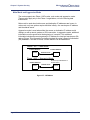
FRF8
IP packets have prepended to them the following sequence: 0x03CC.
NOTE:
This protocol allows sending ATM over Frame Relay.
rawIP
IP packets do not have any protocol headers prepended to them; they appear as IP
packets on the wire. Only IP packets can be transported since there is no possible
method to distinguish other types of packets (bridged frames or IPX).
NOTE:
This protocol allows sending ATM over Frame Relay.
Page 2-12
Efficient Networks®
Efficient Networks® Router family
Technical Reference Guide
Chapter 3: Installation and Setup
CHAPTER 3
CHAPTER 3
INSTALLATION AND SETUP
This chapter describes the steps necessary to plan and deploy your router with basic
operation. Within this chapter, the following steps will be followed to plan for and
configure your router:
•
Planning the Configuration
•
Configuring Your Computer
•
Installation
•
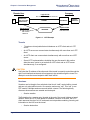
Establishing a Connection
–
Connecting through the Web Management Interface
–
Accessing the Command Line Interface
•
Configuring the Router
•
Verify the Router Configuration
Planning the Configuration
This section describes the basic information you need before you can begin
configuring your router. The basic configuration tasks can be performed using the
Command Line Interface described in this manual or the graphic interface described
in the User Reference Guide (co-located on this CD-ROM). The basic configuration
information is the same for either interface. The basic configuration tasks include the
following:
•
Setting names, passwords, PVC numbers, and link and network parameters
•
Configuring specific protocol requirements, such as IP or IPX addresses and
IP protocol controls
•
Activating bridging and routing protocols
•
Enabling the Internet firewall filter with IP routing
Efficient Networks®
Page 3-1
Efficient Networks® Router family
Technical Reference Guide
Chapter 3: Installation and Setup
Remote Routers
Throughout this document, many references are made to "local routers" and "remote
routers." A local router is the router you are configuring, and the is any other router
that connect to the local router. For additional information on Remote Routers, see
“Controlling Remote Management” on page 5-15.
Local router. Router that you are configuring. Also referred to as target router.
Remote routers. All the routers to which the local (target) router may connect.
Remote router database. Database which resides in the local router and contains
information about the remote routers to which the local router can connect.
Figure 3-1 illustrates these terms.As shown in the illustration, the remote router
database in the local router contains an entry for each remote router. A remote router
entry defines:
•
Connection parameters
•
Security features
•
Route addressing and bridging functions
Local Router
Remote Routers
Router A
Remote router database
Router B
Router C
Router D
Router B
DSL
Network
Router C
Router D
Figure 3-1: Local and Remote Router Overview
The commands that define information for a remote router entry start with the word
remote and end with the name of the remote entry. Most of these commands are
described in the Command Line Interface Guide - Chapter 6, Remote Commands.
For procedures on managing remote use, see “Controlling Remote Management” on
page 5-15.
Page 3-2
Efficient Networks®
Efficient Networks® Router family
Technical Reference Guide
Chapter 3: Installation and Setup
Protocols to be Used
The information needed to configure the router depends on the link protocol and
network protocols that are to be used. The link protocol and network protocols used
are generally determined by your Network Service Provider.
This section is organized into sub-sections that apply to specific protocols.
If you are using Link and Network Protocols:
PPP with:
•
IP Routing, see “IP Routing Network Protocol” on page 3-3.
•
IPX Routing, see “IPX Routing Network Protocol” on page 3-6.
•
Bridging, see “Bridging Network Protocol” on page 3-8.
RFC 1483 or RFC 1490 with:
•
IP Routing, see “IP Routing Network Protocol” on page 3-9.
•
IPX Routing, see “IPX Routing Network Protocol” on page 3-10.
•
Bridging, see “Bridging Network Protocol” on page 3-12.
RFC 1483 MER or RFC 1490 MER (MAC Encapsulated Routing) with:
•
IP Routing, see “IP Routing Network Protocol” on page 3-12.
PPP Link Protocol (over ATM or Frame Relay)
The PPP link protocol is an encapsulation method that can be used over ATM or over
Frame Relay. For PPP over Ethernet (PPPoE), see “PPPoE (PPP over Ethernet)” on
page 6-41.
PPP over ATM and PPP over Frame Relay use different connection identifiers:
•
ATM uses VPI/VCI numbers.
•
Frame Relay uses a DLCI number.
IP Routing Network Protocol
To configure the IP network protocol and PPP link protocol, you need the following
information.
System Names and Authentication Passwords for the Local Router and All Remote
Routers
•
For the Local Router:
You define a system name and authentication password for the local
router. Remote routers check the system name and authentication
password to authenticate the local router.
Efficient Networks®
Page 3-3
Chapter 3: Installation and Setup
•
Efficient Networks® Router family
Technical Reference Guide
For Remote Routers:
Although the system names and authentication passwords for the remote
routers are defined by the service provider, you must have this
information because the local router uses it to authenticate the remote
router. The name and password are used in both PAP and CHAP
authentication. To see how this information is used, see “PAP/CHAP
Security Authentication” on page 5-20.
NOTE:
If the service provider does not support the authentication of remote routers by the
local router, use the command remote disauthen <remoteName> to disable the
authentication process.
For an ATM router, its VPI and VCI numbers
ATM uses two connection identifiers that describe the PVC (Permanent Virtual
Circuit). These identifiers are the VPI (Virtual Path Identifier) and the VCI (Virtual
Channel Identifier). Your router may have been preconfigured with VPI/VCI numbers.
If not, you need to get these numbers from your service provider.
If you are connecting to multiple remote sites, you need the unique VPI and VCI
numbers that identify each remote destination.
For a Frame Relay router, its DLCI number
The DLCI (Data Link Connection Identifier) number applies to Frame Relay routers
only. Get your DLCI from your service provider.
DNS Internet Account Information (optional)
The Domain Name Service (DNS) maps host names to IP addresses. DNS is
performed by Domain Name Servers. The router can get DNS information
automatically. Or, you can choose to configure DNS manually. Consult with your
Network Service Provider to determine if you need to enter the following information:
•
DNS server address
•
DNS second server address
•
DNS domain name
IP Routing Addresses
•
For the Ethernet interface:
Ethernet IP Address (Local LAN)
An Ethernet LAN IP address and subnet mask are required for the
router’s local Ethernet LAN connection. This information is defined by the
user or your network administrator.
Page 3-4
Efficient Networks®
Efficient Networks® Router family
Technical Reference Guide
Chapter 3: Installation and Setup
NOTE:
An Ethernet route is usually defined when there are multiple routers on the Ethernet
that cannot exchange routing information. This feature is only used in special
circumstances.
•
For the WAN interface:
The following information is defined by your network service provider.
Source (Local) WAN Port Address
If Network Address Translation (NAT) is enabled, you must specify a
source WAN IP address for the WAN connection to the remote router if IP
address negotiation under PPP does not provide one. Check with your
network administrator for details on whether the router must
communicate in numbered or unnumbered mode and which addresses
are required.
Remote WAN Address
You may need to specify a remote WAN IP address for the WAN
connection to the remote router depending on IP address negotiation
under PPP. Check with your network administrator for details on whether
the router must communicate in numbered or unnumbered mode and
which addresses are required.
TCP/IP Remote Routes
An IP route includes an IP address, subnet mask, and metric (a number
representing the perceived cost to reach the remote network or station).
A TCP/IP Default Route
A default route should be designated in the routing table for all traffic that
cannot be directed to other specific routes. Define the default route to a
remote router or, in special circumstances, define an Ethernet gateway.
There can be only one default route specified.
Efficient Networks®
Page 3-5
Chapter 3: Installation and Setup
Efficient Networks® Router family
Technical Reference Guide
IPX Routing Network Protocol
System Names and Authentication Passwords for the Local Router and All Remote
Routers
•
For the Local Router:
You define a system name and authentication password for the local
router. Remote routers check the system name and authentication
password to authenticate the local router.
•
For Remote Routers:
Although the system names and authentication passwords for the remote
routers are defined by the service provider, you must have this
information because the local router uses it to authenticate the remote
router. The name and password are used in both PAP and CHAP
authentication. To see how this information is used, see “PAP/CHAP
Security Authentication” on page 5-20.
NOTE:
If the service provider does not support the authentication of remote routers by the
local router, use the command remote disauthen <remoteName> to disable the
authentication process.
For an ATM router, its VPI and VCI numbers
ATM uses two connection identifiers that describe the PVC (Permanent Virtual
Circuit). These identifiers are the VPI (Virtual Path Identifier) and the VCI (Virtual
Channel Identifier). Your router may have been preconfigured with VPI/VCI numbers.
If not, you need to get these numbers from your service provider.
If you are connecting to multiple remote sites, you need the unique VPI and VCI
numbers that identify each remote destination.
For a Frame Relay router, its DLCI number
The DLCI (Data Link Connection Identifier) number applies to Frame Relay routers
only. Get your DLCI from your service provider.
IPX routing entries
IPX routes define the paths to specific destinations. Routers need them so servers
and clients can exchange packets. A path to a file server is based on the Internal
Network Number of the server. A path to a client is based on the External Network
Number (Ethernet) of the client.
Page 3-6
Efficient Networks®
Efficient Networks® Router family
Technical Reference Guide
Chapter 3: Installation and Setup
You need the following information (most likely from your network administrator) for
IPX routing.
Internal Network Number
It is a logical network number that identifies an individual Novell server. It
specifies a route to the services (i.e., file services, print services) that Novell
offers. It must be a unique number.
External Network Number (IPX Network Number)
It refers to a physical LAN/wire network segment to which servers, routers,
and PCs are connected (Ethernet cable-to-router segment). It must be a
unique number.
WAN Network Number
Important: This number is part of the routing information. It only identifies the
WAN segment between the two routers. Note that only those two routers
need to have the WAN Network Number configured.
Service Advertisement Protocol (SAP)
SAP entries should reflect primary logon servers for the clients on the local
LAN. Only the servers on the remote side of the link have to be entered.
Local servers do not need to be entered.
Frame Type
With local servers on your LAN, make sure to select the proper frame type for
the IPX network number. To determine this, consult with your network
administrator. When you have only NetWare clients on your LAN, keep the
default (802.2) selected as most clients can support any type. The frame type
choices are:
802.2
802.3
DIX
Efficient Networks®
Default recommended by Novell
Other most common type
For DEC, Intel, Xerox; this setting is also referred to as “Ethernet II”,
and it is becoming obsolete.
Page 3-7
Chapter 3: Installation and Setup
Efficient Networks® Router family
Technical Reference Guide
Bridging Network Protocol
To configure bridging as the network protocol and PPP as the link protocol, you need
the following information:
System Names and Authentication Passwords for the Local Router and All Remote
Routers
•
For the Local Router:
You define a system name and authentication password for the local
router. Remote routers check the system name and authentication
password to authenticate the local router.
•
For Remote Routers:
Although the system names and authentication passwords for the remote
routers are defined by the service provider, you must have this
information because the local router uses it to authenticate the remote
router. The name and password are used in both PAP and CHAP
authentication. To see how this information is used, see “PAP/CHAP
Security Authentication” on page 5-20.
NOTE:
If the service provider does not support the authentication of remote routers by the
local router, use the command remote disauthen <remoteName> to disable the
authentication process.
For an ATM router, its VPI and VCI numbers
ATM uses two connection identifiers that describe the PVC (Permanent Virtual
Circuit). These identifiers are the VPI (Virtual Path Identifier) and the VCI (Virtual
Channel Identifier). Your router may have been preconfigured with VPI/VCI numbers.
If not, you need to get these numbers from your service provider.
If you are connecting to multiple remote sites, you need the unique VPI and VCI
numbers that identify each remote destination.
For a Frame Relay router, its DLCI number
The DLCI (Data Link Connection Identifier) number applies to Frame Relay routers
only. Get your DLCI from your service provider.
Page 3-8
Efficient Networks®
Efficient Networks® Router family
Technical Reference Guide
Chapter 3: Installation and Setup
DNS Internet Account Information (optional)
The Domain Name Service (DNS) maps host names to IP addresses. DNS is
performed by Domain Name Servers. The router can get DNS information
automatically. Or, you can choose to configure DNS manually. Consult with your
Network Service Provider to determine if you need to enter the following information:
•
DNS server address
•
DNS second server address
•
DNS domain name
RFC 1483/RFC 1490 Link Protocols
The link protocols RFC 1483 and RFC 1490 are multiprotocol encapsulation methods.
RFC 1483 is used over ATM; RFC 1490 is used over Frame Relay.
RFC 1483 and RFC 1490 combined with the IP, IPX, or Bridging network protocols
share the same configuration characteristics, except for the connection identifiers:
VPI/VCI numbers are used for RFC 1483 and a DLCI number is used for RFC 1490.
IP Routing Network Protocol
To configure the IP network protocol and RFC 1483 or RFC 1490 as the link protocol,
you need the following information.
VPI and VCI numbers (for RFC 1483)
The VPI and VCI numbers apply to ATM routers only. Your router may have been
preconfigured with VPI/VCI numbers. If not, get these numbers from your Network
Service Provider.
If you are connecting to multiple remote sites, get additional VPI and VCI numbers
from your Network Service Provider. These numbers identify the remote destination
and must be unique for each remote.
DLCI number (for RFC 1490)
The DLCI (Data Link Connection Identifier) number applies to Frame Relay routers
only. Get your DLCI from your service provider.
DNS Internet Account Information (optional)
Consult with your Network Service Provider to determine if you need to enter the
following information:
•
DNS server address
•
DNS second server address
•
DNS domain name
Efficient Networks®
Page 3-9
Chapter 3: Installation and Setup
Efficient Networks® Router family
Technical Reference Guide
IP Routing Entries
•
For the Ethernet interface:
Ethernet IP Address (Local LAN)
An Ethernet LAN IP address and subnet mask are required for the
router’s local Ethernet LAN connection. This information is defined by the
user or your network administrator.
TCP/IP Ethernet Routes
You normally do not need to define an Ethernet IP route. An Ethernet IP
route consists of an IP address, a mask, a metric, and a gateway. An
Ethernet route is usually defined when there are multiple routers on the
Ethernet that cannot exchange routing information.
•
For the WAN interface:
The following information is defined by your Network Administrator.
Source (Target/Local) WAN Port Address
If Network Address Translation (NAT) is enabled, you must specify a
source WAN IP address for the WAN connection to the remote router.
If NAT is not enabled, you may need to specify a source WAN IP address
for the WAN connection to the remote router.
TCP/IP Remote Routes
An IP route includes an IP address, subnet mask, and metric (a number
representing the perceived cost to reach the remote network or station).
A TCP/IP Default Route
A default route should be designated in the routing table for all traffic that
cannot be directed to other specific routes. Define the default route to a
remote router or, in special circumstances, define an Ethernet gateway.
There can be only one default route specified.
IPX Routing Network Protocol
To configure IPX as the network protocol and RFC 1483 or RFC 1490 as the link
protocol, you need the following information:
VPI and VCI numbers (for RFC 1483)
The VPI and VCI numbers apply to ATM routers only. Your router may have been
preconfigured with VPI/VCI numbers. If not, get these numbers from your Network
Service Provider.
If you are connecting to multiple remote sites, get additional VPI and VCI numbers
from your Network Service Provider. These numbers identify the remote destination
and must be unique for each remote.
Page 3-10
Efficient Networks®
Efficient Networks® Router family
Technical Reference Guide
Chapter 3: Installation and Setup
DLCI number (for RFC 1490)
The DLCI (Data Link Connection Identifier) number applies to Frame Relay routers
only. Get your DLCI from your service provider.
IPX routing entries
IPX routes define the paths to specific destinations. Routers need them so servers
and clients can exchange packets. A path to a file server is based on the Internal
Network Number of the server. A path to a client is based on the External Network
Number (Ethernet) of the client.
You need the following information (most likely from your network administrator) for
IPX routing.
Internal Network Number
It is a logical network number that identifies an individual Novell server. It
specifies a route to the services (i.e., file services, print services) that Novell
offers. It must be a unique number.
External Network Number (IPX Network Number)
It refers to a physical LAN/wire network segment to which servers, routers,
and PCs are connected (Ethernet cable-to-router segment). It must be a
unique number.
WAN Network Number
Important: This number is part of the routing information. It only identifies the
WAN segment between the two routers. Note that only those two routers
need to have the WAN Network Number configured.
Service Advertisement Protocol (SAP)
SAP entries should reflect primary logon servers for the clients on the local
LAN. Only the servers on the remote side of the link have to be entered.
Local servers do not need to be entered.
Frame Type
With local servers on your LAN, make sure to select the proper frame type for
the IPX network number. To determine this, consult with your network
administrator. When you have only NetWare clients on your LAN, keep the
default (802.2) selected as most clients can support any type. The frame type
choices are:
802.2
802.3
DIX
Efficient Networks®
Default recommended by Novell
Other most common type
For DEC, Intel, Xerox; this setting is also referred to as “Ethernet II”,
and it is becoming obsolete.
Page 3-11
Chapter 3: Installation and Setup
Efficient Networks® Router family
Technical Reference Guide
Bridging Network Protocol
To configure bridging as the network protocol and RFC 1483 or RFC 1490 as the link
protocol, you need the following information:
VPI and VCI numbers (for RFC 1483)
The VPI and VCI numbers apply to ATM routers only. Your router may have been
preconfigured with VPI/VCI numbers. If not, get these numbers from your Network
Service Provider.
If you are connecting to multiple remote sites, get additional VPI and VCI numbers
from your Network Service Provider. These numbers identify the remote destination
and must be unique for each remote.
For a Frame Relay router, its DLCI number
The DLCI (Data Link Connection Identifier) number applies to Frame Relay routers
only. Get your DLCI from your service provider.
DNS Internet Account Information (optional)
The Domain Name Service (DNS) maps host names to IP addresses. DNS is
performed by Domain Name Servers. The router can get DNS information
automatically. Or, you can choose to configure DNS manually. Consult with your
Network Service Provider to determine if you need to enter the following information:
•
DNS server address
•
DNS second server address
•
DNS domain name
MAC Encapsulated Routing
MAC Encapsulated Routing (MER) allows IP packets to be carried as bridged frames
(bridged format). The link protocol RFC 1483 with MER (referred to as RFC
1483MER) is a multiprotocol encapsulation method over ATM used by ATM routers.
RFC 1490 with MER (referred to as RFC 1490MER) is a multiprotocol encapsulation
method over Frame Relay used by Frame-Relay routers.
RFC 1483MER and RFC 1490MER combined with the IP, IPX, or Bridging network
protocols share the same configuration characteristics, except for the connection
identifiers: VPI/VCI numbers are used for RFC 1483MER and a DLCI number is used
for RFC 1490.
IP Routing Network Protocol
VPI and VCI numbers (for RFC 1483MER)
The VPI and VCI numbers apply to ATM routers only. Your router may have been
preconfigured with VPI/VCI numbers. If not, get these numbers from your Network
Service Provider and then configure them.
Page 3-12
Efficient Networks®
Efficient Networks® Router family
Technical Reference Guide
Chapter 3: Installation and Setup
If you are connecting to multiple remote sites, get additional VPI and VCI numbers
from your Network Service Provider. These numbers identify the remote destination
and must, therefore, be unique for each remote.
DLCI number (for RFC 1490MER)
The DLCI number applies to Frame Relay routers only. Your Network Service
Provider or your Network Access Provider will provide you with a DLCI (Data Link
Connection Identifier). The DLCI is an address identifying your connection.
DNS Internet Account Information (optional)
Consult with your Network Service Provider to determine if you need to enter the
following information:
•
DNS server address
•
DNS second server address
•
DNS domain name
IP Routing Entries
•
For the Ethernet interface:
Ethernet IP Address (Local LAN)
An Ethernet LAN IP address and subnet mask are required for the
router’s local Ethernet LAN connection. This information is defined by the
user or your network administrator.
TCP/IP Ethernet Routes
You normally do not need to define an Ethernet IP route. An Ethernet IP
route consists of an IP address, a mask, a metric, and a gateway. An
Ethernet route is usually defined when there are multiple routers on the
Ethernet that cannot exchange routing information between them.
•
For the ATM WAN interface:
The following information is defined by your Network Administrator or the
Network Service Provider.
Source (Target/Local) WAN Port Address and Mask
You must specify a Source WAN IP address for the WAN connection to
the remote router (whether or not Network Address Translation is
enabled). The Source WAN Address is the address of the local router on
the remote network. The mask is the mask used on the remote network.
Check with your system administrator for details.
Efficient Networks®
Page 3-13
Chapter 3: Installation and Setup
Efficient Networks® Router family
Technical Reference Guide
If NAT is not enabled, you may need to specify a source WAN IP address
for the WAN connection to the remote router.
TCP/IP Remote Routes
If you are using RFC 1483MER or RFC 1490MER, the IP route includes
an IP address, subnet mask, metric (a number representing the
perceived cost in reaching the remote network or station), and a gateway.
The gateway address that you enter is the address of a router on the
remote LAN. Check with your system administrator for details.
A TCP/IP Default Route
A default route should be designated in the routing table for all traffic that
cannot be directed to other specific routes. Define the default route to a
remote router or, in special circumstances, define an Ethernet gateway.
There can be only one default route specified.
Configuring Your Computer
Your computer must be configured to use the TCP/IP protocol suite over the Internet,
and to accept DHCP (Dynamic Host Configuration Protocol) address assignments
from your router. Although the information and settings required to make such
configurations is standard, differences exist amongst the various computer operating
systems in how these configurations are presented and established. This section
presents the TCP/IP and DHCP configuration screens in the most popular operating
systems, to guide the reader through the configuration process for each operating
system.
You can skip directly to the instructions for your computer operating system from the
following list:
•
•
•
Page 3-14
Microsoft Windows
–
Windows 98
–
Windows NT 4
–
Windows 2000
–
Windows ME
–
Windows XP
Apple Macintosh
–
Macintosh Classic (Mac OS 9.x or earlier)
–
Mac OS X
Linux OS
Efficient Networks®
Efficient Networks® Router family
Technical Reference Guide
Chapter 3: Installation and Setup
Microsoft Windows
Windows 98
Step 1
On your desktop, right click on the Network Neighborhood icon.
Step 2
The Network dialog should appear. Under the Configuration tab, from the network
components installed, select TCP/IP.
Step 3
Click Properties to display TCP/IP properties.
Step 4
In the TCP/IP Properties dialog, select the IP Address tab.
Step 5
Under the IP Address tab, click to select the option to Obtain an IP address
automatically.
Efficient Networks®
Page 3-15
Efficient Networks® Router family
Technical Reference Guide
Chapter 3: Installation and Setup
Step 6
Click OK.
Step 7
Click OK buttons to close each dialog.
NOTE:
You may need to restart your PC for these changes to take effect.
Task Complete
Page 3-16
Efficient Networks®
Efficient Networks® Router family
Technical Reference Guide
Chapter 3: Installation and Setup
Windows NT 4
Step 1
On your desktop, right click on the Network Neighborhood icon.
Step 2
The Network dialog should appear. Under the Protocols tab, from the network
protocols installed, select TCP/IP Protocol.
Step 3
Click Properties to display TCP/IP properties.
Step 4
In the Microstate TCP/IP Properties dialog, select the IP Address tab.
Step 5
Under the IP Address tab, click to select the option to Obtain an IP address from a
DHCP server.
Efficient Networks®
Page 3-17
Efficient Networks® Router family
Technical Reference Guide
Chapter 3: Installation and Setup
Step 6
Click OK.
Step 7
Click OK buttons to close each dialog.
NOTE:
You may need to restart your PC for these changes to take effect.
Task Complete
Page 3-18
Efficient Networks®
Efficient Networks® Router family
Technical Reference Guide
Chapter 3: Installation and Setup
Windows 2000
Step 1
On your desktop, right click on the My Network Places icon.
Step 2
The Network and Dial-up Connections window should appear. Right click on the
Local Area Connection icon.
Step 3
From the menu, select Properties.
Step 4
The Local Area Connection Properties dialog should appear. From the list of
components, select Internet Protocol (TCP/IP).
Efficient Networks®
Page 3-19
Chapter 3: Installation and Setup
Step 5
Step 6
Page 3-20
Efficient Networks® Router family
Technical Reference Guide
Click Properties.
The Internet Protocol (TCP/IP) Properties dialog should appear. Select Obtain an IP
address automatically and Obtain DNS server address automatically.
Efficient Networks®
Efficient Networks® Router family
Technical Reference Guide
Chapter 3: Installation and Setup
Step 7
Click OK.
Step 8
Click OK buttons to close each dialog.
NOTE:
You may need to restart your PC for these changes to take effect.
Task Complete
Efficient Networks®
Page 3-21
Chapter 3: Installation and Setup
Efficient Networks® Router family
Technical Reference Guide
Windows ME
Step 1
On your desktop, right click on the Network Places icon (shown below).
Step 2
From the displayed menu, select Properties.
Step 3
The Network dialog should appear. Under the Configuration tab, from the network
components installed, select the TCP/IP Protocol associated with your network card
(see the example below).
Step 4
Click Properties to display TCP/IP properties.
Step 5
In the TCP/IP Properties dialog, select the IP Address tab.
Page 3-22
Efficient Networks®
Efficient Networks® Router family
Technical Reference Guide
Chapter 3: Installation and Setup
Step 6
Under the IP Address tab, click to select the option to Obtain an IP address
automatically.
Step 7
Click OK.
Step 8
Click OK buttons to close each dialog.
NOTE:
You may need to restart your PC for these changes to take effect.
Task Complete
Efficient Networks®
Page 3-23
Chapter 3: Installation and Setup
Efficient Networks® Router family
Technical Reference Guide
Windows XP
Step 1
On your desktop, click on the My Network Places icon (shown below).
Step 2
The My Network Places screen should appear. Under the Network Tasks menu,
select View Network Connections.
Step 3
The Network Connections screen should appear. Click the Local Area Connection
icon.
Page 3-24
Efficient Networks®
Efficient Networks® Router family
Technical Reference Guide
Chapter 3: Installation and Setup
Step 4
The Local Area Connection Properties dialog should appear. From the list of items,
select Internet Protocol (TCP/IP).
Step 5
Click Properties.
Step 6
Click OK buttons to close each dialog.
NOTE:
You may need to restart your PC for these changes to take effect.
Task Complete
Efficient Networks®
Page 3-25
Chapter 3: Installation and Setup
Efficient Networks® Router family
Technical Reference Guide
Apple Macintosh
To configure TCP/IP and DHCP on your Macintosh, please select your version of the
Mac OS from the following list:
•
Mac OS 9.x
•
Mac OS X
Mac OS 9.x
Step 1
Page 3-26
Under the Apple menu, select Control Panels and then TCP/IP.
Efficient Networks®
Efficient Networks® Router family
Technical Reference Guide
Chapter 3: Installation and Setup
Step 2
The TCP/IP control panel should appear. From the Configure pull-down menu,
select: Using DHCP Server.
Step 3
Complete the fields shown with any information supplied by your service provider.
Step 4
Click on the upper left square in the menu bar to close the TCP/IP control panel.
Task Complete
Efficient Networks®
Page 3-27
Chapter 3: Installation and Setup
Efficient Networks® Router family
Technical Reference Guide
Mac OS X
Step 1
Under the Apple menu, select System Preferences.
Step 2
The System Preferences window should appear. Click to select the Network icon.
Page 3-28
Efficient Networks®
Efficient Networks® Router family
Technical Reference Guide
Chapter 3: Installation and Setup
Step 3
The Network window should appear. Select the TCP/IP tab.
Step 4
From the Configure pull-down menu, select Using DHCP.
Step 5
Enter any information supplied by your service provider.
Step 6
Click Save button to save and exit the Network window.
Task Complete
Efficient Networks®
Page 3-29
Chapter 3: Installation and Setup
Efficient Networks® Router family
Technical Reference Guide
Linux
Step 1
From a terminal window, run linuxconfig.
Step 2
The Config dialog should appear. Enter any information specified by your service
provider in the fields under the appropriate Adapter tab.
Page 3-30
Efficient Networks®
Efficient Networks® Router family
Technical Reference Guide
Chapter 3: Installation and Setup
Step 3
When settings are completed, Click Accept.
Step 4
To update the system status, ensure that the "Activate the changes" button is
highlighted, then click Act/Changes.
Task Complete
Efficient Networks®
Page 3-31
Chapter 3: Installation and Setup
Efficient Networks® Router family
Technical Reference Guide
Installation
Verify the Package Contents
Your package should contain the items listed below. If you determine anything to be
damaged or missing, please contact the dealer from whom the equipment was
purchased.
•
One Efficient Networks 5900 Series Business gateway
•
One Efficient Networks Documentation CD-ROM
•
One AC power adapter
•
One Ethernet cable, RJ-45
•
One ADSL cable, RJ-11, or an additional RJ-45 cable (modem 5950) for
SHDSL connection
•
One RJ-45 to DB-9 serial port adapter (console)
•
One 5900 Series Quick-Start Guide (varies per router model)
•
One Safety and Certifications Sheet
•
Customer Release Notes with the latest information
Connecting the Router
Step 1
Place your router in a location where it will be well ventilated. Do not stack it with
other devices or place it on carpet.
Step 2
Connect your PC directly to any of the routers eight Ethernet ports, using one of the
RJ-45 Ethernet cables. You may also connect additional Ethernet devices to the
router’s Ethernet ports.
Step 3
Connect your router to the DSL jack
•
Use the RJ-11 cable (purple label) for models 5930 and 5935
•
Use the RJ-45 cable model 5950.
CAUTION:
To reduce the risk of fire, use only no. 26 AWG or larger telecommunications line cord.
Such cords are used to connect your DSL port on your router to the DSL (telephone)
jack.
Step 4
Page 3-32
Optionally, if you will be using the serial interface to perform configuration tasks from
the Command Line Interface, connect an Ethernet cable form one of your your PC’s
serial ports to the MGMT Console port on the rear of the router.
Efficient Networks®
Efficient Networks® Router family
Technical Reference Guide
Step 5
Chapter 3: Installation and Setup
Connect the AC power adapter to the Router then to AC power outlet.
Task Complete
Efficient Networks®
Page 3-33
Efficient Networks® Router family
Technical Reference Guide
Chapter 3: Installation and Setup
Establishing a Connection
To start the configuration, communication must be established with the router. The
system can be accessed in the following ways:
•
Ethernet connection - via an Ethernet port on the rear of the router.
•
Serial - local via the MGMT Console serial port on the rear of the router.
Another consideration in configuring your unit is the type of user interface; there are
two user interfaces available on the router:
•
Web Management Interface - the Web Management Interface (WMI) is an
HTML-based interface that provides easy to use graphical screens for simple
configuration of your router. The WMI is not available over the serial port.
•
Command-line interface - provides a way to perform custom configurations
utilizing the full command set of the system by typing parameters at a
command prompt. The command line interface is available through the serial
port using terminal emulation software, or remotely through a network node
that can reach the unit using the LAN or WAN IP address using TELNET.
Connecting through the Web Management Interface
Step 1
Using your web browser, enter the following default router address into the address
field of your browser:
http://192.168.254.254/
Step 2
At the login prompt, make the following entries:
User Name: superuser
Password: admin
Step 3
After you have logged into your, you will be prompted to change the default
password. Enter the new password information as required.
Step 4
When prompted, log-in again with the new user account information.
Task Complete
Accessing the Command Line Interface
To use the Command Line Interface, you must first access the router command line.
To do this, perform the following steps:
Step 1
Page 3-34
If not previously connected, connect a PC (or ASCII) terminal to a port of the router.
(The required cable and adapter are provided with the router. The connection
procedure is described in detail in the User Reference Guide that came with the
router.)
Efficient Networks®
Efficient Networks® Router family
Technical Reference Guide
Chapter 3: Installation and Setup
Step 2
Restart the PC and power on the router.
Step 3
Open a terminal window or start a terminal session on the PC.
Step 4
The router displays the login prompt. Login with the username superuser.
Username:
Step 5
The router displays the password prompt, enter the login password (default
password is admin.
Password:
NOTE:
The password will be displayed as *****
Step 6
A confirmation is returned; the command line interface is now available.
Logged in successfully!
Step 7
If the default login password (admin) was used a message will be displayed.
**************************************************************
WARNING: You must change your password from the default value!
**************************************************************
Step 8
Enter a new password at the prompt.
Enter New Password:
Step 9
Enter a new password at the prompt.
Enter New Password Again:
The password change will be confirmed:
Password changed.
The command line is now available for use.
Task Complete
Efficient Networks®
Page 3-35
Chapter 3: Installation and Setup
Efficient Networks® Router family
Technical Reference Guide
Terminal Sessions
The router supports both local access and remote access. In step 3 above, the
terminal session could be:
•
Terminal Session under Windows (HyperTerminal) or Terminal Session for
Macintosh or UNIX (for local access)
•
Telnet Session for Remote Access
Terminal Session under Windows (HyperTerminal)
To open the HyperTerminal emulator available under the Windows operating system:
Step 1
Click Start on the Windows taskbar, then select:
> Programs
> Accessories
> Communications
> Hyperterminal
> Hyper Terminal
The HyperTerminal window will appear in the background and you will be prompted
for configuration information.
Step 2
In the Connection Description window, enter a name for the connection and select
OK.
Step 3
In the Phone Number window, under Connect using, select Com 1 (or 2).
Page 3-36
Efficient Networks®
Efficient Networks® Router family
Technical Reference Guide
Step 4
Chapter 3: Installation and Setup
In the Com 1 (or 2) Properties page, enter the following port settings and click OK:
Bits per second: 9600a
Data bits:
Parity:
Stop bits:
Flow control:
a To
8
None
1
Hardware
use a baud rate other than 9600, see “Option 7: Set Console Baud Rate” on page 4-39.
Task Complete
Efficient Networks®
Page 3-37
Efficient Networks® Router family
Technical Reference Guide
Chapter 3: Installation and Setup
Terminal Session for Macintosh or UNIX
To open a terminal window emulation in a Macintosh or UNIX environment, a VT100
terminal emulation program is required.
Step 1
Start your VT100 terminal emulator.
Step 2
Configure the emulator with the following settings:
Bits per second: 9600a
8
Data bits:
None
Parity:
1
Stop bits:
Flow control: Hardware
a To
use a baud rate other than 9600, see “Option 7: Set Console Baud Rate” on page 4-39.
Task Complete
Page 3-38
Efficient Networks®
Efficient Networks® Router family
Technical Reference Guide
Chapter 3: Installation and Setup
Telnet Session for Remote Access
From the local area network you can use TELNET to login in using the Ethernet IP
address.
NOTE:
Remote access to the router configuration can be disabled or restricted. For further
information, see “Controlling Remote Management” on page 5-15.
Step 1
Make sure that your PC and router addresses are in the same subnetwork. For
example, the router address could be 192.168.254.254 and the PC address could be
192.168.254.253.
Step 2
Start a TELNET session.
a. If you are using a PC running Windows“ 95/98/NT“, select Start > Run. If on a
UNIX system, bring up a shell window.
b. In the Run dialog box (or shell) window, enter:
telnet 192.168.254.254
c. Click OK, or press <Enter>.
Step 3
A TELNET window will be launched; a line identifying the router will be displayed,
followed by the Login: prompt as shown below.
Efficient 5950 G.SHDSL [ATM] Router (5950-001) v6.0.0 Ready
Username:
Task Complete
Efficient Networks®
Page 3-39
Chapter 3: Installation and Setup
Efficient Networks® Router family
Technical Reference Guide
Configuring the Router
Having planned your configuration and acquired the necessary information as
described in Planning the Configuration, you are ready to configure your router. If you
will be configuring the system though the Web management Interface, please refer to
the User Reference Guide located on this CD. The content to follow details the
configuration via the command line interface.
This section assumes that you have:
•
installed the router hardware,
•
connected to the router with a terminal emulation session (or ASCII terminal),
and,
•
powered the unit on.
This section contains configuration commands for each combination of link protocol
and network protocol supported by the router. (Your Network Service Provider
determines the link protocol that you use.)
For complete, individual descriptions of the commands mentioned in this section,
hyperlinks are provided to the command syntax of the Command Line Interface
Guide.
NOTE:
If you are setting up both ends of the network, use a mirror image of the information
listed below for configuring the router on the other end of the link.
Important: If you change any the of the following settings, you must save the change
and then either reboot the router or restart the interface for the change to take effect:
Ethernet LAN: Ethernet IP or IPX address, TCP/IP routing, IPX routing
Bridging: Bridging, filters
Remote Router: TCP/IP route addresses, IPX routes, IPX SAPs and bridging control,
and enable, disable, or add remote routers
Page 3-40
Efficient Networks®
Efficient Networks® Router family
Technical Reference Guide
Chapter 3: Installation and Setup
Configuration Tables
The following tables provide step-by-step instructions for enabling standard
configurations of the following network protocol/link protocol combinations via the
command line interface. For instruction on protocol/link configuration via the Web
Management Interface, see “Easy Setup” on page 8-4.
Table 3-1: Configuration Tables
Link Protocol
Network Protocol
Configuration Table
PPP
IP Routing
Table 3-2, “PPP with IP Routing”
PPP
IPX Routing
Table 3-3, “PPP with IPX Routing”
PPP
Bridging
Table 3-4, “PPP with Bridging”
RFC 1483
IP Routing
Table 3-5, “RFC 1483 / RFC 1490 with IP Routing”
RFC 1490
IP Routing
Table 3-5, “RFC 1483 / RFC 1490 with IP Routing”
RFC 1483
IPX Routing
Table 3-6, “RFC 1483 / RFC 1490 with IPX Routing”
RFC 1490
IPX Routing
Table 3-6, “RFC 1483 / RFC 1490 with IPX Routing”
RFC 1483
Bridging
Table 3-7, “RFC 1483 / RFC 1490 with Bridging”
RFC 1490
Bridging
Table 3-7, “RFC 1483 / RFC 1490 with Bridging”
RFC 1483MER
IP Routing
Table 3-8, “RFC 1483MER / RFCMER 1490 with IP
Routing”
RFC 1490MER
IP Routing
Table 3-8, “RFC 1483MER / RFCMER 1490 with IP
Routing”
Efficient Networks®
Page 3-41
Efficient Networks® Router family
Technical Reference Guide
Chapter 3: Installation and Setup
Configuring PPP with IP Routing
This table outlines configuration commands for the PPP link protocol with the IP
Routing network protocol.
Table 3-2: PPP with IP Routing
Steps
Settings
Commands
System Settings
System Name
Required
system name <name>
System Message
Optional
system msg <message>
Authentication
Password
Required
system passwd <password>
Ethernet IP Address
As Required
eth ip addr <ipaddr> <ipnetmask> [<port#>]
DHCP Settings
Already enabled;
additional settings
may be required
dhcp set valueoption domainname <domain-
name>
dhcp set valueoption domainnameserver <ipad-
dr>
Change Login
Optional
password <password>
Remote Routers
New Entry
Enter: Remote
Name
remote add <remoteName>
Link Protocol/PVCa
(for ATM routers)
Select: PPP
Enter: VPI/VCI
numbers
remote setprotocol ppp <remoteName>
remote setpvc<vpi number>*<vci number> <re-
moteName>
Link Protocol/DLCIb
(for Frame Relay
routers)
Select: PPP
Enter: DLCI number
remote setprotocol ppp <remoteName>
remote setdlci <number> <remoteName>
Security c
Remote’s Password
Choose security
level
Enter: password
remote setauthen <protocol> <remoteName>
remote setourpasswd <password> <remote-
Name>
Bridging On/Off
Must be off
remote disbridge <remoteName>
TCP/IP Route Address
Enter: Explicit or
default route
<remoteName>
If NAT is enabled:
To enable NAT,
use:
remote setiptranslate on <remoteName>
You may need to
enter a Source
WAN Port Address
Name>
Page 3-42
remote addiproute <ipnet> <ipnetmask> <hops>
remote setsrcipaddr <ipaddr> <mask> <remote-
Efficient Networks®
Efficient Networks® Router family
Technical Reference Guide
Chapter 3: Installation and Setup
Table 3-2: PPP with IP Routing (Cont.)
Steps
If NAT is not enabled:
Settings
Commands
You may need to
enter a Source
WAN Port Address
remote setsrcipaddr <ipaddr> <mask> <remote-
Name>
IP and IPX Routing
TCP/IP Routing
(Internet Firewall)
Must be enabled
(optional)
eth ip enable
eth ip firewall <on | off>
IPX Routing
Must be disabled
eth ipx disable
Store
Reboot
save
reboot
a
Enter this information if you are using PPP in an ATM environment.
this information if you are using PPP in a Frame Relay environment.
c If the ISP does not support the authentication of the ISP system by the caller, use the command
remote disauthen <remoteName> to disable the authentication.
b Enter
Configuring PPP with IPX Routing
This table outlines configuration commands for the PPP link protocol with the IPX
Routing network protocol.
Table 3-3: PPP with IPX Routing
Steps
Settings
Commands
System Settings
System Name
Required
system name <name>
System Message
Optional
system msg <message>
Authentication Password
Required
system passwd <password>
Ethernet IP Address
As Required
eth ip addr <ipaddr> <ipnetmask> [<port#>]
DHCP Settings
Already enabled;
additional settings
may be required
dhcp set valueoption domainname <domain-
name>
dhcp set valueoption domainnameserver <ipad-
dr>
Change Login
Optional
password <password>
Ethernet IPX Network
#
Enter: IPX network #
Frame Type (default: 802.2)
eth ipx addr <ipxnet> [<port#>]
eth ipx frame <type>
Efficient Networks®
Page 3-43
Efficient Networks® Router family
Technical Reference Guide
Chapter 3: Installation and Setup
Table 3-3: PPP with IPX Routing (Cont.)
Steps
Settings
Commands
Remote Routers
New Entry
Enter: Remote
Name
remote add <remoteName>
Link Protocol/PVCa
(for ATM routers)
Select: PPP
Enter: VPI/VCI numbers
remote setprotocol ppp <remoteName>
remote setpvc <vpi number>*<vci number> <re-
moteName>
Link Protocol/DLCIb
(for Frame Relay routers)
Select: PPP
Enter: DLCI number
remote setprotocol ppp <remoteName>
remote setdlci <number> <remoteName>
Security c
Remote’s Password
Choose security level
Enter: password
remote setauthen <protocol> <remoteName>
remote setourpasswd <password> <remote-
Name>
Bridging On/Off
Must be off
remote disbridge <remoteName>
Add IPX Routes
Enter appropriate
info
remote addipxroute <ipxNet> <metric> <ticks>
Add IPX SAPs
Enter appropriate
info
remote setipxaddr <ipxNet> <remoteName>
WAN Network #
Enter appropriate
info
remote setipxaddr <ipxNet> <remoteName>
<remoteName>
IP and IPX Routing
TCP/IP Routing
Must be disabled
eth ip disable
IPX Routing
Must be enabled
eth ipx enable
Store
Reboot
save
reboot
a Enter
this information if you are using PPP in an ATM environment.
Enter this information if you are using PPP in a Frame Relay environment.
c If the ISP does not support the authentication of the ISP system by the caller, use the command
remote disauthen <remoteName> to disable the authentication.
b
Page 3-44
Efficient Networks®
Efficient Networks® Router family
Technical Reference Guide
Chapter 3: Installation and Setup
Configuring PPP with Bridging
This table outlines configuration commands for the PPP link protocol with the Bridging
network protocol.
Table 3-4: PPP with Bridging
Steps
Settings
Commands
System Settings
System Name
Required
system name <name>
System Message
Optional
system msg <message>
Authentication
Password
Required
system passwd <password>
Ethernet IP Address
As Required
eth ip addr <ipaddr> <ipnetmask> [<port#>]
DHCP Settings
Already enabled;
additional settings
may be required
dhcp set valueoption domainname <domain-
name>
dhcp set valueoption domainnameserver <ipad-
dr>
Change Login
Optional
password <password>
Remote Routers
New Entry
Enter: Remote
Name
remote add <remoteName>
Link Protocol/PVCa
(for ATM routers)
Select: PPP
Enter: VPI/VCI
numbers
remote setprotocol ppp <remotename>
remote setpvc <vpi number>*<vci number> <re-
moteName>
Link Protocol/DLCIb
(for Frame Relay
routers)
Select: PPP
Enter: DLCI number
remote setprotocol ppp <remotename>
remote setdlci <number> <remoteName>
Security c
Remote’s Password
Choose security
level
Enter: password
remote setauthen <protocol> <remoteName>
remote setourpasswd <password> <remote-
Name>
Bridging On/Off
Must be on
remote enabridge <remoteName>
TCP/IP Route Address
Enter: Explicit or
default route
<remoteName>
If NAT is enabled:
To enable NAT,
use:
remote setiptranslate on <remoteName>
You may need to
enter a Source
WAN Port Address
name>
Efficient Networks®
remote addiproute <ipnet> <ipnetmask> <hops>
remote setsrcipaddr <ipaddr> <mask> <remote-
Page 3-45
Efficient Networks® Router family
Technical Reference Guide
Chapter 3: Installation and Setup
Table 3-4: PPP with Bridging (Cont.)
Steps
If NAT is not enabled:
Settings
Commands
You may need to
enter a Source
WAN Port Address
remote setsrcipaddr <ipaddr> <mask> <remote-
Name>
IP and IPX Routing
TCP/IP Routing
Must be disabled
eth ip disable
IPX Routing
Must be disabled
eth ipx disable
Store
Reboot
save
reboot
a Enter
this information if you are using PPP in an ATM environment.
Enter this information if you are using PPP in a Frame Relay environment.
c If the ISP does not support the authentication of the ISP system by the caller, use the command
remote disauthen <remoteName> to disable the authentication.
b
Configuring RFC 1483 / RFC 1490 with IP Routing
This table outlines configuration commands for the RFC 1483 and the RFC 1490 link
protocols with the IP Routing network protocol.
Table 3-5: RFC 1483 / RFC 1490 with IP Routing
Steps
Settings
Commands
System Settings
System Message
Optional
system msg <message>
Ethernet IP Address
As Required
eth ip addr <ipaddr> <ipnetmask> [<port#>]
DHCP Settings
Already enabled;
additional settings
may be required
dhcp set valueoption domainname <domain-
name>
dhcp set valueoption domainnameserver <ipad-
dr>
Change Login
Optional
password <password>
Remote Routers
New Entry
Enter: Remote
Name
remote add <remoteName>
Link Protocol/PVCa
(for ATM routers)
Select: PPP
Enter: VPI/VCI
numbers
remote setprotocol ppp <remotename>
remote setpvc <vpi number>*<vci number> <re-
Page 3-46
moteName>
Efficient Networks®
Efficient Networks® Router family
Technical Reference Guide
Chapter 3: Installation and Setup
Table 3-5: RFC 1483 / RFC 1490 with IP Routing (Cont.)
Steps
Settings
Commands
Link Protocol/DLCIb
(for Frame Relay
routers)
Select: PPP
Enter: DLCI number
remote setprotocol ppp <remotename>
remote setdlci <number> <remoteName>
Bridging On/Off
Must be off
remote disbridge <remoteName>
TCP/IP Route Address
Enter: Explicit or
default route
<remoteName>
If NAT is enabled:
To enable NAT,
use:
TCP/IP Route Addresses
Enter: Source
WAN Port Address
If NAT is not enabled:
You may still need to
enter a Source
WAN Port Address
remote addiproute <ipnet> <ipnetmask> <hops>
remote setiptranslate on <remoteName>
remote setsrcipaddr <ipaddr> <mask> <remote-
Name>
remote setsrcipaddr <ipaddr> <mask> <remote-
Name>
IP and IPX Routing
TCP/IP Routing
(Internet Firewall)
Must be enabled
(optional)
eth ip enable
eth ip firewall <on | off>
IPX Routing
Must be disabled
eth ipx disable
Store
Reboot
a
save
reboot
Enter this information if you are using RFC 1483 in an ATM environment.
this information if you are using RFC 1490 in a Frame Relay environment.
b Enter
Efficient Networks®
Page 3-47
Efficient Networks® Router family
Technical Reference Guide
Chapter 3: Installation and Setup
Configuring RFC 1483 / RFC 1490 with IPX Routing
This table outlines configuration commands for the RFC 1483 and RFC 1490 link
protocols with the IPX Routing network protocol.
Table 3-6: RFC 1483 / RFC 1490 with IPX Routing
Steps
Settings
Commands
System Settings
System Message
Optional
system msg <message>
Ethernet IP Address
As Required
eth ip addr <ipaddr> <ipnetmask> [<port#>]
DHCP Settings
Already enabled;
additional settings
may be required
dhcp set valueoption domainname <domain-
name>
dhcp set valueoption domainnameserver <ipad-
dr>
Ethernet IPX Network
#
Enter: IPX Network
# Frame Type (default is 802.2)
eth ipx frame <type>
Change Login
Optional
password <password>
Remote Routers
New Entry
Enter: Remote
Name
remote add <remoteName>
Link Protocol/PVCa
(for ATM routers)
Select: RFC 1483
Enter: VPI/VCI numbers
remote setprotocol rfc1483 <remotename>
remote setpvc <vpi number>*<vci number> <re-
moteName>
Link Protocol/DLCIb
(for Frame Relay routers)
Select: FR
Enter: DLCI number
remote setprotocol fr <remotename>
remote setdlci <number> <remotename>
Bridging On/Off
Must be off
remote disbridge <remoteName>
IPX Routes Add
Enter appropriate
info
remote addipxroute <ipxNet> <metric> <ticks>
IPX SAPs Add
Enter appropriate
info
remote addipxsap <servicename> <ipxNet>
< ipxNode> <socket> <type> <hops> <remoteName>
WAN Network Number
Enter appropriate
info
remote setipxaddr <ipxNet> <remoteName>
<remoteName>
IP and IPX Routing
TCP/IP Routing
(Internet Firewall)
Page 3-48
Must be disabled
(optional)
eth ip enable
eth ip firewall <on | off>
Efficient Networks®
Efficient Networks® Router family
Technical Reference Guide
Chapter 3: Installation and Setup
Table 3-6: RFC 1483 / RFC 1490 with IPX Routing (Cont.)
Steps
IPX Routing
Settings
Commands
Must be enabled
Store
Reboot
eth ipx enable
save
reboot
a Enter
b
this information if you are using RFC 1483 in an ATM environment.
Enter this information if you are using RFC 1490 in a Frame Relay environment.
Configuring RFC 1483 / RFC 1490 with Bridging
This table outlines configuration commands for the RFC 1483 and RFC 1490 link
protocols with the Bridging network protocol.
Table 3-7: RFC 1483 / RFC 1490 with Bridging
Steps
Settings
Commands
System Settings
System Message
Optional
system msg <message>
DHCP Settings
Already enabled;
additional settings
may be required
dhcp set valueoption domainname <domain-
name>
dhcp set valueoption domainnameserver <ipad-
dr>
Change Login
Optional
password <password>
Remote Routers
New Entry
Enter: Remote
Name
remote add <remoteName>
Link Protocol/PVCa
(for ATM routers)
Select: RFC1483
Enter: VPI/VCI
numbers
remote setprotocol rfc1483 <remotename>
remote setpvc <vpi number>*<vci number> <re-
moteName>
Link Protocol/DLCIb
(for Frame Relay
routers)
Select: FR
Enter: DLCI number
remote setprotocol fr <remotename>
remote setdlci <number> <remoteName>
Bridging On/Off
Must be on
remote enabridge <remoteName>
If NAT is not enabled:
You may need to
enter a Source
WAN Port Address
Name>
remote setsrcipaddr <ipaddr> <mask> <remote-
IP and IPX Routing
IP Routing
Efficient Networks®
Must be disabled
eth ip disable
Page 3-49
Efficient Networks® Router family
Technical Reference Guide
Chapter 3: Installation and Setup
Table 3-7: RFC 1483 / RFC 1490 with Bridging (Cont.)
Steps
Settings
IPX Routing
Commands
Must be disabled
Store
Reboot
eth ipx disable
save
reboot
a Enter
b
this information if you are using RFC 1483 in an ATM environment.
Enter this information if you are using RFC 1490 in a Frame Relay environment.
Configuring RFC 1483MER / RFC 1490MER with IP Routing
This table outlines configuration commands for the RFC 1483MER and RFC
1490MER link protocols with the IP Routing network protocol.
Table 3-8: RFC 1483MER / RFCMER 1490 with IP Routing
Steps
Settings
Commands
System Settings
System Message
Optional
system msg <message>
Ethernet IP Address
As Required
eth ip addr <ipaddr> <ipnetmask> [<port#>]
DHCP Settings
Already enabled;
additional settings
may be required
dhcp set valueoption domainname <domain-
name>
dhcp set valueoption domainnameserver <ipad-
dr>
Change Login
Optional
password <password>
Remote Routers
New Entry
Enter: Remote
Name
remote add <remoteName>
Link Protocol/PVCa
(for ATM routers)
Select: RFC
1483MER
Enter: VPI/VCI numbers
remote setprotocol rfc1mer <remotename>
remote setpvc <vpi number>*<vci number> <re-
moteName>
Link Protocol/DLCIb
(for Frame Relay routers)
Select: MER
Enter: DLCI number
remote setprotocol mer <remotename>
remote setdlci <number> <remoteName>
Bridging On/Off
Must be off
remote disbridge <remoteName>
If NAT is enabled:
To enable NAT,
use:
remote setiptranslate on <remoteName>
Page 3-50
Efficient Networks®
Efficient Networks® Router family
Technical Reference Guide
Chapter 3: Installation and Setup
Table 3-8: RFC 1483MER / RFCMER 1490 with IP Routing (Cont.)
Steps
Settings
Commands
If NAT is not enabled:
Enter: Source
WAN Port Address
+ mask of the remote network
TCP/IP Route Addresses
Enter: Source
WAN Port Address
+ mask of the remote network’s
mask
remote setsrcipaddr <ipaddr> <mask> <remote-
Name>
remote setsrcipaddr <ipaddr> <mask> <remote-
Name>
IP and IPX Routing
TCP/IP Routing
(Internet Firewall)
Must be disabled
(optional)
eth ip enable
eth ip firewall <on | off>
IPX Routing
Must be disabled
eth ipx disable
Store
Reboot
a
save
reboot
Enter this information if you are using RFC 1483 in an ATM environment.
this information if you are using RFC 1490 in a Frame Relay environment.
b Enter
Verify the Router Configuration
This section contains procedures to verify the router configuration testing IP, IPX and
bridging.
Test IP Routing
Test IP Routing over the Local Ethernet LAN (from PC)
•
Use the TCP/IP ping command or a similar method to contact the configured
local router specifying the Ethernet LAN IP address. The LEDs on the router
should flash for each ping received.
•
If you cannot contact the router, verify that the Ethernet IP address and
subnet mask are correct and check the cable connections.
•
Make sure that you have saved and rebooted after setting the IP address.
•
Check Network TCP/IP properties under Windows 95. If you are running
Windows 3.1, check that you have a TCP/IP driver installed.
Efficient Networks®
Page 3-51
Chapter 3: Installation and Setup
Efficient Networks® Router family
Technical Reference Guide
Test IP Routing to a Remote Destination
•
Using the TCP/IP ping command, contact a remote router from a local LANconnected PC. When you enter the ping command, the router will connect to
the remote router using the DSL line.
•
If remote or local WAN IP addresses are required, verify that they are valid.
•
Use the iproutes command to check, first, the contents of the IP routing table
and, second, that you have specified a default route as well.
Test Routing from a Remote Destination
Have a remote router contact the local router using a similar method.
Test TCP/IP Routes
•
Contact a station, subnetwork, or host located on the network beyond a
remote router to verify the TCP/IP route addresses entered in the remote
router database.
•
Verify that you configured the correct static IP routes.
•
Use the iproutes command to check the contents of the IP routing table.
Test Bridging to a Remote Destination
Use any application from a local LAN-attached station that accesses a server or disk
using a protocol that is being bridged on the remote network beyond the remote
router. If you cannot access the server:
•
Verify that you have specified a default destination remote router.
•
Make sure that you have enabled bridging to the remote router.
•
Check that bridge filtering does not restrict access from the local station.
Test IPX Routing
One way to test IPX routing is to check for access to servers on the remote LAN.
Under Windows, use the NetWare Connections selection provided with NetWare User
Tools. Under DOS, use the command pconsole or type login on the login drive
(usually F:). Select the printer server and verify that the server you have defined is
listed. When you attempt to access the server, the router will connect to the remote
router using the DSL line.
Page 3-52
Efficient Networks®
Efficient Networks® Router family
Technical Reference Guide
Chapter 3: Installation and Setup
If you cannot access the remote server:
•
Check that the local Ethernet LAN IPX network number is correct.
•
Verify that the WAN link network number is the same as the remote WAN link
network number.
•
Check cable connections and pinouts.
•
Verify that the IPX routes and IPX SAPs you have specified are correct.
•
List the contents of the routing and services tables using the ipxroutes and
ipxsaps commands, respectively.
•
Make sure that the security authentication method and password that you
configured match the remote router.
Efficient Networks®
Page 3-53
Chapter 3: Installation and Setup
Efficient Networks® Router family
Technical Reference Guide
This page intentionally left blank.
Page 3-54
Efficient Networks®
Efficient Networks® Router family
Technical Reference Guide
Chapter 4: System Management
CHAPTER 4
CHAPTER 4
SYSTEM MANAGEMENT
This chapter provides information on a variety of system features and procedures.
These features include:
•
DHCP (Dynamic Host Configuration Protocol)
•
BootP Service
•
Network Address Translation (NAT)
•
Key Enabled Features
•
Spanning Tree
•
Boot Code Options
•
Software Kernel Upgrades
•
Quality of Service (QOS)
•
Misc. Administrative Functions
The router has several other features that are discussed in other section of this
document. A list supplying links to some of these features is provided below.
•
“IP Filtering” on page 5-23
•
“L2TP Tunneling - Virtual Dial-Up” on page 6-26
•
“PAP/CHAP Security Authentication” on page 5-20
•
“Radius” on page 5-10
•
“SNMP” on page 7-2
•
“SSH” on page 5-70
•
“Stateful Firewall” on page 5-34
•
“User Authentication” on page 5-2
•
“VPN” on page 6-46
•
“WEB Management Interface” on page 8-1
Efficient Networks®
Page 4-1
Chapter 4: System Management
Efficient Networks® Router family
Technical Reference Guide
DHCP (Dynamic Host Configuration Protocol)
The router supports DHCP and can act as the DHCP server. (The router’s DHCP
server disables itself if it locates other active DHCP servers on the network or if a
DHCP server on the WAN has been explicitly specified.)
When configured, the router can provide DHCP functions as follows:
•
As a server, IP addresses are assigned to workstations attached to the LAN
that issue DHCP address requests.
•
As a client, the router requests that an IP address be assigned to the WAN
side port of the router.
•
As a relay, the router passes through client requests from the LAN side onto
the WAN asking for IP address assignment and relays responses back to the
appropriate client.
This section describes how to configure DHCP. The procedures that follow illustrate
the process using the Command Line Interface; to configure DHCP via the WMI, use
the DCHP Configuration page (page 8-35). Configuring DHCP can be a complex
process; this section is therefore intended for network managers. For a complete list
and explanation of the DHCP commands, refer to the Command Line Interface Guide:
Chapter 8, DHCP Commands.
NOTE:
Some DHCP values can be set using the Windows Quick Start application, the
Windows Configuration Manager, or the web-based EZ Setup application.
DHCP Address Allocation
DHCP is a service that allocates IP addresses automatically to any DHCP client
requesting an IP address. (A DHCP client can be any device attached to your
network, for example, a PC.) It can also provide option values (such as the subnet
mask, DNS, and gateway values) automatically.
Using DHCP to automatically acquire initialization parameters translates into avoiding
the more involved router/PC manual initialization process. (The manual initialization
requires re-configuration of router and/or PC addresses to be in the same network.)
To configure DHCP for a network, the network administrator defines a range of valid
IP addresses to be used in the subnetwork as well as options and other parameters.
This process is described in the next section, DHCP Administration and
Configuration.
NOTE:
DHCP is effective only if the TCP/IP stack is installed on the PCs.
Page 4-2
Efficient Networks®
Efficient Networks® Router family
Technical Reference Guide
Chapter 4: System Management
NOTE:
For information on configuring the PC for DHCP, see “Configuring Your Computer” on
page 3-14.
DHCP Client Requests
Before becoming active, the router’s DHCP server attempts to locate other active
DHCP servers on the network, such as Windows NT servers. If one is detected, the
router’s DHCP server disables itself.
When the WAN link activates and the source IP address or mask is undefined (i.e.
0.0.0.0), the router places a DHCP client request over the WAN link. The router may
learn the following parameters:
•
DNS address
•
Default gateway
•
Syslog server IP address
•
Time server IP address
•
Source IP address to use
To see the gateway and source IP addresses that were returned, use the iproutes
command.
The IP addresses and options assigned to a client are collectively called the “lease”.
The lease is only valid for a certain period of time and is automatically renewed by the
client.
DHCP Administration and Configuration
The DHCP administration and configuration process is divided into the following
functions:
•
Manipulating Subnetworks and Explicit Client Leases
•
Setting Option Values
•
Managing BootP
•
Configuring BootP/DHCP Relays
•
Defining Option Types
•
Other information
The configuration procedures that follow are based on entering the commands
through the Command Line Interface, for configuration via the Web Management
interface, see “DCHP Configuration” on page 8-35.
Efficient Networks®
Page 4-3
Chapter 4: System Management
Efficient Networks® Router family
Technical Reference Guide
Manipulating Subnetworks and Explicit Client Leases
Enabling/Disabling a Subnetwork or a Client Lease
To enable/disable a subnetwork or a client lease, use the commands:
-> dhcp enable all | <net> <ipaddr>
-> dhcp disable all| <net> <ipaddr>
Examples
To enable the subnetwork 192.168.254.0 if that subnetwork exists, enter:
-> dhcp enable 192.168.254.0
To enable the client lease 192.168.254.17 if that client lease exists, enter:
-> dhcp enable 192.168.254.17
To disable the client lease 192.168.254.18 if that client lease exists, enter:
-> dhcp disable 192.168.254.18
To check the results of these commands, use:
-> dhcp list
If the client lease does not exist, it must be explicitly created.
Adding a Subnetwork
The following commands are used to add/delete subnetworks. Only one subnetwork
with one pool of IP addresses may be defined for a subnet.
To add a subnetwork, use:
-> dhcp add <net> <mask>
To remove a subnetwork, use:
-> dhcp del <net>
NOTE:
All client leases associated with this subnetwork are automatically deleted.
Page 4-4
Efficient Networks®
Efficient Networks® Router family
Technical Reference Guide
Chapter 4: System Management
Example 1:
The following command creates a subnetwork 192.168.254.0 with a subnet mask of
255.255.255.0:
-> dhcp add 192.168.254.0 255.255.255.0
Example 2:
The following command deletes the subnetwork 192.168.254.0 and deletes all client
leases associated with that subnetwork:
-> dhcp del 192.168.254.0
Adding Explicit or Dynamic Client Leases
Client leases may either be created dynamically or explicitly. Usually client leases are
created dynamically when PCs boot and ask for IP addresses.
Explicit client leases
To add an explicit client lease, a subnetwork must already exist. Use the following
command before adding the client lease:
-> dhcp add <net> <mask>
Once the lease has been added, use the following command to assign the lease to
the client:
-> dhcp add <ipaddr>
To remove a client lease, use:
-> dhcp del <ipaddr>
NOTE:
An administrator may create a client lease that is part of a subnet but does not fall
within the pool of IP addresses.
Example 1:
To explicitly add the client lease 192.168.254.31, enter:
->
dhcp add 192.168.254.31
Example 2:
To delete the client lease 192.168.254.31, enter:
->
dhcp del 192.168.254.31
Efficient Networks®
Page 4-5
Chapter 4: System Management
Efficient Networks® Router family
Technical Reference Guide
Dynamic Client Leases
Dynamic client leases are created from the pool of IP addresses associated with that
subnetwork.
To set or change the pool, use:
-> dhcp set addresses <first ip addr> <last ip addr>
To clear the values from the pool, use:
-> dhcp clear addresses <net>
NOTE:
Any client leases that currently exist will not be affected.
To remove a client lease that was dynamically created, use:
-> dhcp del <ipaddr>
CAUTION:
If the <ipaddr> parameter is a subnet, you will delete the entire subnet.
Setting the Lease Time
The information given by the DHCP server (router) to your PC is leased for a specific
amount of time. The client lease has already been selected. The DHCP server will
select the lease time based on the option defined for the client lease as described by
this algorithm:
1. If the client lease option is a specific number or is infinite, then the server uses
the specified lease time associated with this client lease.
2. If the client lease option is “default”, then the server goes up one level (to the
subnetwork) and uses the lease time explicitly specified for the subnetwork.
3. If the client and subnetwork lease options are both “default”, then the server
goes up one level (global) and uses the lease time defined at the global level
(server).
4. Lease time:
The minimum lease time is 1 hour.
The global default is 168 hours.
Page 4-6
Efficient Networks®
Efficient Networks® Router family
Technical Reference Guide
Chapter 4: System Management
Commands
The following commands are used by network administrators to control lease time.
To set the lease time explicitly for the client lease, use:
-> dhcp set lease <ipaddr> <hours>
To set the lease time explicitly for the subnetwork lease, use:
-> dhcp set lease <net> <hours>
To set the lease time explicitly for the global lease, use:
-> dhcp list lease <hours>
Example 1:
To set the lease time to “default” for the client 192.168.254.17, enter:
-> dhcp set lease 192.168.254.17 default
Example 2:
To set the subnetwork lease time to infinite for the subnet 192.168.254.0, enter:
-> dhcp set lease 192.168.254.0 infinite
Example 3:
To set the global lease time to 2 hours, enter:
-> dhcp set lease 2
Manually Changing Client Leases
In general, administrators do not need to change client leases manually. However, if
the need arises to do so, the following two commands are used.
CAUTION:
The client will not be aware that the administrator has changed or released a client
lease!
To change the client lease expiration time to a given value, use the following
command:
-> dhcp set expire <ipaddr> <hours>
Setting the expiration time to “default” will cause the server to compute the lease time
using the algorithm as described in “Setting the Lease Time” on page 4-6.
Efficient Networks®
Page 4-7
Chapter 4: System Management
Efficient Networks® Router family
Technical Reference Guide
To release the client lease so it becomes available for other assignments, enter:
-> dhcp clear expire <ipaddr>
Setting Option Values
Administrators can set values for global options, for options specific to a subnetwork,
or for options specific to a client lease.
NOTE:
See RFC 2131/2132 for the description of various options.
The DHCP server returns values for options explicitly requested in the client request.
It selects the values to return based on the following algorithm:
1. If the value is defined for the client, then the server returns the requested
value for an option.
2. If the value for the option has not been set for the client, then the server
returns the value option if it has been defined for the subnetwork.
3. If the value option does not exist for the client and does not exist for the
subnetwork, then the server returns the value option if it has been defined
globally.
4. If the value option is not defined anywhere, the server does not return any
value for that option in its reply to the client request.
Important: When the server replies to a client:
•
It does not return any option values not requested by the client.
•
It does not support the definition of a “class” of clients.
•
It does not return any non-default option values unless the client requests the
option value and the server has a value defined for that option.
•
It does not return any non-default values on the clients subnet unless the
client requests the value for that option.
Commands for Global Option Values
To set the value for a global option, enter:
-> dhcp set valueoption <code> <value>
The code can be a number between 1 and 61 or a <keyword>.
To see the list of predefined and user-defined options, enter:
-> dhcp list definedoptions
To clear the value for a global option, use:
Page 4-8
Efficient Networks®
Efficient Networks® Router family
Technical Reference Guide
Chapter 4: System Management
-> dhcp clear valueoption <code>
Example:
To set the global value for the domain name server option, enter:
-> dhcp set valueoption domainnameserver 192.168.254.2
192.168.254.3
Commands for Specific Option Values for a Subnetwork
To set the value for an option associated with a subnetwork, enter:
-> dhcp set valueoption <net> <code> <value>
To clear the value for an option associated with a subnetwork, enter:
-> dhcp clear valueoption <net> <code>
Examples:
-> dhcp set valueoption 192.168.254.0 gateway 192.168.254.254
-> dhcp set valueoption 6 192.84.210.75 192.84.210.68
Commands for Specific Option Values for a Client Lease
To set the value for an option associated with a specific client, enter:
-> dhcp set valueoption <ipaddr> <code> <value>
To clear the value for an option associated with a specific client, enter:
-> dhcp clear valueoption <ipaddr> <code>
Example:
-> dhcp set valueoption 192.168.254.251 winserver 192.168.254.7
Commands for Listing and Checking Option Values
To list the values for global options as well as subnet and client lease information,
enter:
-> dhcp list
To list options that are set for that subnet/client lease as well as subnet/client lease
information, enter:
-> dhcp list <net> | <code>
This command lists all available options (predefined and user-defined options):
Efficient Networks®
Page 4-9
Chapter 4: System Management
Efficient Networks® Router family
Technical Reference Guide
-> dhcp list definedoptions
This command lists all available options starting with the string “name”.
-> dhcp list definedoptions <name>
To list the lease time, enter:
-> dhcp list lease
Example:
This command lists the subnet 192.168.254.0 including any options set specifically for
that subnet:
-> dhcp list 192.168.254.0
Managing BootP
Administrators can enable and disable BootP and specify the BootP server. BootP
can be enabled at the subnetwork and at the client lease level.
NOTE:
By default, the DHCP server does not satisfy BootP requests unless the administrator
has explicitly enabled BootP (at the subnetwork or lease level).
About BootP and DHCP
BootP and DHCP provide services that are very similar. However, as an older service,
BootP offers only a subset of the services provided by DHCP.
The main difference between BootP and DHCP is that the client lease expiration for a
BootP client is always infinite.
NOTE:
Remember, when BootP is enabled, the client assumes that the lease is infinite.
Enable/Disable BootP
To allow BootP request processing for a particular client/subnet, use the command:
-> dhcp bootp allow <net> | <ipaddr>
To disallow BootP request processing for a particular client/subnet, enter:
-> dhcp bootp disallow <net> | <ipaddr>
Page 4-10
Efficient Networks®
Efficient Networks® Router family
Technical Reference Guide
Chapter 4: System Management
Specify the Boot (TFTP) Server
The following commands let the administrator specify the TFTP server (boot server)
and boot file name. The administrator should first configure the IP address of the
TFTP server and file name (kernel) from which to boot.
To set the IP address of the server and the file to boot from, use the following
commands:
-> dhcp bootp tftpserver <net> | <ipaddr> | <tftpserver ipaddr>
-> dhcp bootp file [<net> | <ipaddr>] | <filename>
To clear the IP address of the server and the file to boot from, enter:
-> dhcp bootp tftpserver [<net> | <ipaddr>] 0.0.0.0
Example 1:
To set the global BootP server IP address to 192.168.254.7:
-> dhcp bootp tftpserver 192.168.254.7
Example 2:
To set the subnet 192.168.254.0 server IP address to 192.168.254.8:
-> dhcp bootp tftpserver 192.168.254.0 192.168.254.8
Example 3:
To set the client 192.168.254.21 server IP address to 192.168.254.9, enter:
-> dhcp bootp tftpserver 192.168.254.21 192.168.254.9
Example 4:
To set the subnet 192.168.254.0 boot file to “kernel.100”:
-> dhcp bootp file 192.168.254.0 kernel.100
Example 5:
To clear the global BootP server IP address and file name:
-> dhcp bootp tftpserver 0.0.0.0
Example 6:
To clear the subnet 192.168.254.0 server IP address and file name:
-> dhcp bootp tftpserver 192.168.254.0 0.0.0.0
Efficient Networks®
Page 4-11
Chapter 4: System Management
Efficient Networks® Router family
Technical Reference Guide
Configuring BootP/DHCP Relays
BootP/DHCP relays are used by system administrators when the DHCP configuration
parameters are acquired from a BootP/DHCP server other than the router’s DHCP
server.
This function allows configuration information to be centrally controlled. Enabling a
BootP/DHCP relay disables DHCP on the router because, by definition, only one
policy mechanism can be supported.
However, multiple relays may be specified. BootP/DHCP requests are forwarded to
every relay on the list. It is assumed, in this case, that the multiple servers are
configured to recognize the requests that they are to handle.
To add a BootP/DHCP Relay address to the list, use the command:
-> dhcp addrelay <ipaddr>
To remove a BootP/DHCP Relay address from the list, use the command:
-> dhcp delrelay <ipaddr>
Defining Option Types
A DHCP option is a code, length, or value. An option also has a “type” (byte, word,
long, longint, binary, IP address, string).
The subnet mask, router gateway, domain name, domain name servers, NetBios
name servers are all DHCP options. Refer to RFC 1533 if you require more
information.
Users will normally not need to define their own option types. The list of predefined
option types based on RFC 1533 can be shown by using the dhcp list definedoptions
command.
Commands
The following commands are available for adding/deleting option types:
-> dhcp add <code> <min> <max> <type>
To list option types that are currently defined, enter:
-> dhcp list definedoptions...
To list the definitions for all known options, enter:
-> dhcp list definedoptions
To list the definition for option 1, if option 1 is defined, type:
-> dhcp list definedoptions 1
Page 4-12
Efficient Networks®
Efficient Networks® Router family
Technical Reference Guide
Chapter 4: System Management
To list the definition for all options that are well-known AND have a name starting with
“h”, type:
-> dhcp list definedoptions h
Example:
To define a new option with a code of 128, a minimum number of IP addresses of 1, a
maximum number of IP addresses of 4, of type “IP address”, enter:
-> dhcp add 128 1 4 ipaddress
This information implies that:
•
Some DHCP client will know about the option with code 128.
•
Option 128 allows IP addresses.
•
The server can have a minimum of 1 IP address.
•
The server can have up to 4 IP addresses.
•
The administrator will still need to set the option value either globally, specific
to a subnetwork, or specific to a client for the option to have any meaning.
To delete the definition of the option with code 128, type:
-> dhcp del 128
The values for this option that have been set globally, specific to a subnetwork, or
specific to a client will not be removed. The administrator must remove those values
explicitly. Well-known type option codes cannot be changed or deleted.
DHCP Information File
DHCP information is kept in the file DHCP.DAT, a self-contained file.
This file contains all DHCP information including:
•
the option definitions
•
the subnetworks that have been added
•
the client lease information
•
the option values that have been set
This file can be uploaded/downloaded from one router to another.
Efficient Networks®
Page 4-13
Chapter 4: System Management
Efficient Networks® Router family
Technical Reference Guide
Clearing All DHCP Information
If necessary, you can clear all DHCP information from memory, including all leases
and all global DHCP information. To do so, enter this command:
-> dhcp clear all records
At this point, the DHCP information is cleared from memory, but the DHCP.DAT file
remains unchanged. To clear the information from the DHCP.DAT file as well, enter:
-> save
NOTE:
You cannot abbreviate the word records in the dhcp clear all records command.
Page 4-14
Efficient Networks®
Efficient Networks® Router family
Technical Reference Guide
Chapter 4: System Management
BootP Service
This section first discusses what BootP is and then describes the BootP service
available from the router.
BootP Concepts
BootP refers to the Bootstrap Protocol. In general, BootP requests have these
purposes:
•
To obtain an IP address to use.
•
To obtain a TFTP server address and file information to continue the booting
up process.
For example, a diskless workstation could use a BootP request to get an IP address
for itself, the TFTP server address where it is to get the kernel it is to load and run,
and the file name of that kernel.
A BootP server waits for incoming BootP broadcasts from BootP clients. The server
looks up the MAC addresses of the incoming BootP request in its database. If the
MAC address is found, the server normally responds to the requestor with an IP
address. It may also respond with boot information, that is, the IP address of a TFTP
server, and the name of a file.
BootP Service by the DHCP Server
BootP is a subset of DHCP. The router has a DHCP (Dynamic Host Configuration
Protocol) server (as described in detail on page 4-2). By default, the DHCP server
ignores BootP requests. However, if desired, you can enable the DHCP server in the
router to process BootP requests. BootP processing can be enabled globally, on a per
subnetwork basis, or on a per client (IP address) basis. For more information, see
“Managing BootP” on page 4-10.
If the DHCP server in the router is disabled, it, of course, cannot process BootP
requests even if BootP processing is enabled. The DHCP server in the router disables
itself if one of the following occurs:
•
If another DHCP server is active on the network.
•
If you enter the commands dhcp disable all and save.
•
If the DHCP relay list contains one or more IP addresses.
Efficient Networks®
Page 4-15
Chapter 4: System Management
Efficient Networks® Router family
Technical Reference Guide
Relaying BootP Requests
The DHCP relay list is an optional list of IP addresses of servers on the network. You
create the list manually; addresses are not automatically added or removed. You add
addresses to the list using the dhcp addrelay command and remove addresses from
the list using the dhcp delrelay command.
While the relay list contains at least one address, the DHCP server in the router is
disabled, and the router forwards all DHCP requests and BootP requests to all
servers in the relay list. It forwards every reply received from any of the servers in the
relay list to the appropriate LAN.
If you remove all addresses from the DHCP relay list, the DHCP server is re-enabled
and resumes processing DHCP requests and also BootP requests if BootP
processing is enabled.
Page 4-16
Efficient Networks®
Efficient Networks® Router family
Technical Reference Guide
Chapter 4: System Management
Network Address Translation (NAT)
Network Address Translation (NAT) allows devices on the LAN to use private IP
addresses that aren’t recognized on the Internet. The router supports the following
NAT techniques:
Masquerading:
Classic NAT:
Selective NAT:
One NAT IP address is assigned to many PC IP addresses.
One NAT IP address is assigned to one PC IP address.
Specified IP address is assigned based on packet destination.
NOTE:
Some applications that use IP or UDP protocols may have problems with Network
Address Translation. You may be able to avoid this problem by running in TCP mode
or by disabling NAT and running as a subnetwork to your ISP.
Supported applications include AOL chat, CUSeeMe, Doom, FTP, L2TP, HTTP, Kali
Netbios over IP, NetMeeting, PCanywhere, Quake, Quicktime Video, Real Audio,
RTSP, SGI Media Base, SMTP, StreamWorks, Telnet, TFTP, Unix commands (finger,
rcp, rshell, rlogin, whois) and VDO. To read more, see “NetMeeting (H.323) with NAT”
on page 4-27.
General NAT Rules
•
IP routing must be enabled.
•
NAT can be run globally or on a per-remote-router and per-Ethernet-interface
basis.
•
Some operations will not work. Specifically, services that place IP address/
port information in the data may not work until the router examines their
packets and figures out what information in the data needs to be changed.
Remember that the router is remapping both IP addresses and ports.
•
When using NAT with a remote router, either the remote ISP must supply the
IP address for NAT translation or the user must configure the IP address for
NAT translation locally.
•
Any number of PCs on the LAN may have a connection to the same or
different remote routers at the same time. In reality, the number of PCs on
the LAN that can be supported is limited by the amount of memory
consumed by the router to maintain table information and by the number of
connections the router “thinks” are currently active. Theoretically, up to
64,000 active connections per protocol type—TCP/UDP—can be
concurrently running, if the table space is available.
Efficient Networks®
Page 4-17
Chapter 4: System Management
Efficient Networks® Router family
Technical Reference Guide
Masquerading
With masquerading, multiple local (PC) IP addresses are mapped to a single global IP
address. Many local (PCs) IP addresses are therefore hidden behind a single global
IP address. The advantage of this type of NAT is that users only need one global IP
address, but the entire local LAN can still access the Internet. This NAT technique
requires not only remapping IP addresses but also TCP and UDP ports.
Each PC on the LAN side has an IP address and a mask. When the router connects
to an ISP, the router appears to be a “host” with one IP address and mask. The IP
address that the router uses to communicate with the ISP is obtained dynamically
(with PPP/IPCP or DHCP) or is statically configured. When the PC connects to the
ISP, the IP address and port used by the PC are remapped to the IP address
assigned to the router. This remapping is done dynamically.
Client Configuration
The following procedures present client configuration from the CLI, for enabling NAT
via the WMI, see “NAT” on page 8-38.
Enable NAT
To enable NAT for a remote interface, use the commands:
-> remote setiptranslate on <remotename>
-> save
To enable NAT for an Ethernet interface, use the commands:
-> eth ip translate on <interface>
-> save
The save command makes the above changes persistent across reboots; these
changes turn NAT on when the specified interface is used.
Obtain an IP Address for NAT
The IP address (the IP address “known” by the remote ISP) used for this type of NAT
can be assigned in two ways.
The ISP dynamically assigns the IP address. Use the commands:
-> remote setsrcipaddr 0.0.0.0 0.0.0.0 <remotename>
-> save
The IP address is assigned locally. Use the commands:
-> remote setsrcipaddr ww.xx.yy.zz 255.255.255.255 <remotename>
-> save
Page 4-18
Efficient Networks®
Efficient Networks® Router family
Technical Reference Guide
Chapter 4: System Management
NOTE:
ww.xx.yy.zz is the IP address that the user on the local LAN assigns.
Server Configuration
This section is intended for users and network administrators who wish to allow WAN
access to a Web server, FTP server, SMTP server, etc., on their local LAN, while
using NAT.
NAT needs a way to identify which local PC [local IP address(es)] should receive
these server requests. The servers can be configured on a per-remote-router and perEthernet-interface basis as well as globally.
Interface-Specific Commands
You can specify servers for specific remote interfaces and for specific Ethernet
interfaces. Servers can also be designated for specific protocols and ports. To enable
and disable a local IP address (on your LAN) as the server for a specific remote
interface, use the following commands:
-> remote addserver <action> <protocol> [<last port> [<first
private port>]] <remotename>
-> remote delserver <action> <protocol> [<last port> [<first
private port>]] <remotename>
To see all of the remote entries, use the command:
-> remote list <remotename>
To enable and disable a local IP address (on your LAN) as the server for a specific
Ethernet interface, use the following commands:
-> eth ip addserver <action> <protocol> [<last port> [<first
private port>]] <interface>
-> eth ip delserver <action> <protocol> [<last port> [<first
private port>]] <interface>
NOTE:
Enter a save command to make the changes persistent across reboots.
Example 1
Assume that the local LAN network is 192.168.1.0 255.255.255.0. The following
commands enable a Telnet server on the local LAN with the IP address 192.168.1.3,
and an FTP server with the IP address 192.168.1.2.
-> remote addserver 192.168.1.3 tcp telnet router1
Efficient Networks®
Page 4-19
Chapter 4: System Management
Efficient Networks® Router family
Technical Reference Guide
-> remote addserver 192.168.1.2 tcp ftp router1
When the local router receives a request from router1 to communicate with the local
Telnet server, the local router sends the request to 192.168.1.3. If router1 asks to talk
to the local FTP server, the local router sends the request to 192.168.1.2.
Example 2
Assume that the local LAN network is 192.168.1.0 255.255.255.0. When the port
value of 0 (zero) is used, it directs all ports of the specified protocol to the IP address
specified.
-> remote addserver 192.168.1.2 tcp 0 router1
NOTE:
addserver commands using specific port numbers take priority over the port 0 setting.
192.168.1.4 will be asked to serve requests coming from router1 to the local router. If
the local router also has the same Telnet and FTP entries from the previous example,
192.168.1.3 will serve the Telnet request, 192.168.1.2 will serve the FTP request, and
192.168.1.4 will serve any other request, including HTTP, SMTP, etc.
Example 3
In this example, an incoming request on TCP port 9000 will be sent to 192.168.1.10
with the port changed from 9000 to the telnet port (port 23).
-> remote addserver 192.168.1.10 tcp 9000 9000 telnet route-in
-> remote addserver 192.168.1.11 tcp 9001 9001 telnet route-in
An incoming request on TCP port 9001 will be sent to 192.168.1.11 with the port
changed from 9001 to the telnet port.
Error Message: “Failed to add server”
The error message Failed to add server indicates that a server entry could not be
created. This can occur either due to port overlap or due to not enough memory.
Port overlap
For example, you enter:
-> remote addserver 192.168.1.10 tcp 9000 9000 telnet router1
-> remote addserver 192.168.1.11 tcp 9000 9000 telnet router1
Failed to add server
Page 4-20
Efficient Networks®
Efficient Networks® Router family
Technical Reference Guide
Chapter 4: System Management
The second command gets an error due to port overlap. If the second server entry
was allowed and the remote end sends a server request to port 9000, the router
wouldn’t know whether to send the request to 192.168.1.10 or 192.168.1.11.
Not enough memory was available to create an entry.
This condition should not ordinarily occur because the amount of memory needed for
a server entry is less than 30 bytes. Should this problem occur, it may cause many
related problems or failures.
System Commands
The following two commands are used to globally enable/disable a local IP address
(on your LAN) as the server for that particular protocol and/or port.
-> system addserver <action> <protocol> <port> [<last port>
[<first private port>]]
-> system delserver <action> <protocol> <port> [<last port>
[<first private port>]]
NOTE:
Enter save to make the changes persistent across boots.
Examples:
The router sends a server request for SMTP to 192.168.1.5 when such a request
comes from any remote router running NAT. The router sends any other server
request (tcp or udp) to 192.168.1.6.
-> system addserver 192.168.1.5 tcp smtp
-> system addserver 192.168.1.6 tcp 0
-> system addserver 192.168.1.6 udp 0
Efficient Networks®
Page 4-21
Chapter 4: System Management
Efficient Networks® Router family
Technical Reference Guide
Server Request Hierarchy
As shown earlier, multiple system addserver, remote addserver, and eth ip addserver
commands can designate different servers for different protocols, ports, and
interfaces. When handling a request from a remote router (to which the local router
has NAT enabled), the local router searches the server list for the appropriate server.
The following lists the order of search and the command that added the server to the
list:
Search Order
1. Protocol and port for a specific interface
Command
-> remote addserver or
-> eth ip addserver
2. Protocol and port for any interface
-> system addserver
3. Protocol and any port for a specific interface
-> remote addserver
with port 0 or
-> eth ip addserver
with port 0
4. Protocol and any port for any interface
-> system addserver
with port 0
5. Any protocol and any port for a specific interface -> remote addserver
with protocol all and port 0
-> eth ip addserver
with protocol all and port 0
6. Any protocol and any port for any interface
->system addserver
with protocol all and port 0
7. Local LAN IP address mapped to the WAN
interface IP address.
-> system addhostmapping
8. If none of the above, the local router selects
itself (the local router) as the server.
Page 4-22
Efficient Networks®
Efficient Networks® Router family
Technical Reference Guide
Chapter 4: System Management
Classic NAT
With classic NAT, one PC IP address is translated to one NAT IP address. This NAT
technique is primarily used to make certain hosts on a private LAN globally visible and
give them the ability to remap these IP addresses as well.
Client Configuration
Classic NAT requires that you first enable NAT Masquerading (as described in the
previous section); thus, for the Classic and Masquerading forms of NAT, the clients
are configured in the same way; see “Client Configuration” on page 4-18.
Host Remapping
Interface-Specific Commands
You can enable and disable host remapping for specific remote interfaces and for
specific Ethernet interfaces. To enable or disable host remapping on a per-remote
basis, use these commands:
-> remote addhostmapping <first privaddr> <second privaddr>
<first publicaddr> <remotename>
-> remote delhostmapping <first privaddr> <second privaddr>
<first publicaddr> <remotename>
Use the command remote addhostmapping whenever a host on the local LAN is
known by different IP addresses to different remotes.
To enable or disable host remapping on a per-Ethernet-interface basis, use these
commands:
-> eth ip addhostmapping <first privaddr> <second privaddr>
<first publicaddr> <interface>
-> eth ip delhostmapping <first privaddr> <second privaddr>
<first publicaddr> <interface>
System Commands
Use these commands to enable or disable host remapping system-wide:
-> system addhostmapping <first privaddr> <second privaddr>
<first publicaddr>
-> system delhostmapping <first privaddr> <second privaddr>
<first publicaddr>
Use the command system addhostmapping whenever a host on the local LAN is
known by the same IP address on all remotes.
Efficient Networks®
Page 4-23
Chapter 4: System Management
Efficient Networks® Router family
Technical Reference Guide
IP Address Range
The range of local LAN IP addresses to be remapped is defined by <first private
addr> to <second private addr> inclusive. These addresses are mapped one-to-one
to the public addresses.
The range of public IP addresses is defined by <first public addr> only. The rest of the
range is computed automatically (from <first public addr> to <first public addr> +
number of addresses remapped - 1) inclusive.
Multiple-Host Remapping Entries
Users may enter as many host remapping entries as they wish.
Example:
The following entries create three mappings:
•
192.168.207.40 through 192.168.207.49 are mapped to 10.0.20.11 through
10.0.20.20
•
192.168.207.93 through 192.168.207.99 are mapped to 10.0.20.4 through
10.0.20.10
•
192.168.209.71 through 192.168.209.80 are mapped to 10.12.14.16 through
10.12.14.25
remote addhostmapping 192.168.207.40 192.168.207.49 10.0.20.11
remote1
remote addhostmapping 192.168.207.93 192.168.207.99 10.0.20.4
remote1
remote addhostmapping 192.168.209.71 192.168.209.80 10.12.14.16
remote1
Page 4-24
Efficient Networks®
Efficient Networks® Router family
Technical Reference Guide
Chapter 4: System Management
Range Overlap Rules
•
The per-interface commands, remote addhostmapping and eth ip
addhostmapping have these range overlap rules:
Private IP address ranges cannot overlap for an interface.
Public IP address ranges cannot overlap for an interface.
•
The global command, system addhostmapping, has these range overlap
rules:
Private IP address ranges cannot overlap for a system.
Public IP address ranges cannot overlap for a system.
•
If a private IP address range for an interface and a private IP address range
for the system overlap, the private IP address range for the interface has
precedence.
•
If a public IP address range for an interface and the public IP address range
for the system overlap, the public IP address range for the interface has
precedence.
•
Private IP addresses and public IP addresses can be the same.
For example, to enable IP/port translation to a remote router and make the IP
addresses 10.1.1.7 through 10.1.1.10 globally visible, it is permissible to use either
one of the following commands:
-> remote addhostmapping 10.1.1.7 10.1.1.10 10.1.1.7 remoteName
-> system addhostmapping 10.1.1.7 10.1.1.10 10.1.1.7
If the remapped host’s IP address (classic NAT, one-to-one IP address translation)
and the masquerading IP address (many-to-one IP address translation) are the same,
then NAT masquerading has precedence over classic NAT.
Selective NAT
A third implementation of performing NAT is called Selective NAT. In this method,
translation is performed on the basis of the destination address. Selective NAT
policies can be configured to specify the destination address and the public address
that the private addresses will need to be translated to, if translation is desired.
Creating Policies
The NAT policies define the NAT translation based on the destination address of the
outgoing packet. The policies contain the public address that the private addresses
will be translated to. Thus, if a selective NAT policy is found for the outgoing packet,
the private address on the packet will be translated to be public address specified in
the policy.
Selective NAT policies are created with two commands; one that will, based on the
destination address, translate the private address to a user-defined public address.
Efficient Networks®
Page 4-25
Chapter 4: System Management
Efficient Networks® Router family
Technical Reference Guide
system selnat addpolicy <remote addr> <remote mask> trans
<public address>
and one that will, based on the destination address, allow the private address to
remain visible. These commands are:
system selnat addpolicy <remote addr> <remote mask> notrans
When policies are created, they are sorted and assigned a policy number on the basis
of the subnet mask. The most specific policy will be number policy 1 and applied first
followed sequentially by the more general policies.
A default policy can be specified that will be applies to all destinations not defined by
other policies. This default policy can provide translation similar to masquerading with
the exceptions of a user defined translation address, the destination address range
can be more narrowly defined, and any other policies would be acted on first, based
on the more specific subnet.
Examples
This command creates the default policy.
system selnat addpolicy 0.0.0.0 0.0.0.0 trans 12.35.10.1
This command creates a policy that will translate the source address of any packets
destined to the subnet 12.16.32.0. to 64.35.6.1.
system selnat addpolicy 12.16.32.0 255.255.255.0 trans 64.35.6.1
This command creates a policy that, for any packets going to the destination address
10.2.2.2, will have no translation performed.
system selnat addpolicy 10.2.2.2 255.255.255.0 notrans
The composite effect of these policies will be: Packets destined to any address in the
subnet 12.16.32.0 will have the source address translated to 64.35.6.1. Packets going
to the destination address 10.2.2.2 will not have any translation done. Packets going
to any destination other than the 12.16.32.0 subnet and 10.2.2.2 will be translated to
12.35.10.1.
Page 4-26
Efficient Networks®
Efficient Networks® Router family
Technical Reference Guide
Chapter 4: System Management
Viewing Policies
The policy listing is sorted by policy number; showing more specific policies first
followed by the more general policies. To list the Selective NAT policies, use the
following command:
system selnat list
The following response would be displayed from the examples policies added
previously:
-> system selnat list
Remote address
1. 10.2.2.2/255.255.255.255
2. 12.16.32.0/255.255.255.0
3. 0.0.0.0/0.0.0.0
Action
No Translation
Transle to 64.35.6.1
Transle to 12.35.10.1
Deleting Policies
Policies are deleted based on the policy number. To delete a policy, use the following
command:
system selnat delpolicy <policy number>
NetMeeting (H.323) with NAT
NetMeeting is an application that uses the TCP protocol H.323 (and, for certain
options, T.120). If all NetMeeting connections are outgoing, NAT does not interfere
and no additional configuration is needed. However, if incoming NetMeeting calls from
outside the local LAN are to be received, NAT needs additional directions from you.
NAT prevents requests coming from outside the LAN from connecting to private
addresses on the LAN unless you specify the connections that are to be allowed.To
receive NetMeeting audio and video connections from outside the local LAN while
NAT is enabled, you must enter commands to direct the outside connections. To do
this, you would enter commands to either:
•
direct connections for TCP ports 1720 (h323) and 1503 (t120), or
•
map a public IP address to a private IP address on the LAN.
Scenario 1: Global Server Connection
Let’s suppose you want one private IP address on the local LAN to receive
NetMeeting audio and video connections from outside the LAN while NAT is enabled.
To allow this, you specify the IP address on the following command:
-> system addserver <ipaddr> tcp h323
The NetMeeting options, Share Program, Chat, Whiteboard, and Transfer Files use
the TCP protocol T.120. To use these options, enter another command specifying the
IP address, as follows:
Efficient Networks®
Page 4-27
Chapter 4: System Management
Efficient Networks® Router family
Technical Reference Guide
-> system addserver <ipaddr> tcp t120
All IP addresses on the LAN can continue to connect to addresses outside the LAN,
but only the specified IP address can receive the specified TCP connections from the
outside.
Scenario 2: Interface-Specific Server Connection
Scenario 2 is the same as scenario 1, except that you want to limit the connections
from outside to a specific interface. For a remote interface, you specify the IP address
and the remote name on the following commands:
-> remote addserver <ipaddr> tcp h323 <remote>
-> remote addserver <ipaddr> tcp t120 <remote>
For a dual-Ethernet router where the connection to the WAN is through an Ethernet
interface, you would use these commands that specify the IP address and the
Ethernet interface that is connected to the WAN:
-> eth ip addserver <ipaddr> tcp h323 <interface>
-> eth ip addserver <ipaddr> tcp t120 <interface>
Scenario 3: Address Remapping
If the local LAN has more than one IP address visible from the WAN, you could map
one of those visible IP addresses to a private IP address on the LAN. The router
would then direct all connections for the “outside” IP address to the “inside” IP
address. The command to do this is:
-> system addhostmapping <private ipaddr> <privateipaddr>
<publicipaddr>
The first two parameters specify the first and last addresses in the address range. To
remap just one address, you specify the same private address twice and then the
public IP address.
Address remapping can also be done for a specific interface. For a remote interface,
you would specify the addresses and the remote name on the following command:
-> remote addhostmapping <private ipaddr> <privateipaddr>
<publicipaddr> <remote>
For an Ethernet interface, you would specify the addresses and the Ethernet interface
on this command:
-> eth ip addhostmapping <private ipaddr> <privateipaddr>
<publicIpaddr> <interface>
Page 4-28
Efficient Networks®
Efficient Networks® Router family
Technical Reference Guide
Chapter 4: System Management
Key Enabled Features
The router has several optional features that can be enabled by purchasing Feature
Activation keys. Depending on the router configuration when ordered, the Feature
Activation keys may have been installed during the router manufacturing process or
may need to be installed in the field. These optional features are:
•
3DES Encryption
•
DES Encryption
•
Internal V.90 modem
•
IP stack check
•
IP Filtering
•
IP Security
•
IP Stack
•
L2TP Tunneling
•
Radius Client
•
SSH Secure Shell
•
Quality of Service
•
Stateful Firewall
•
VPN Accelerator
The features are activated by the presence of a specific key file in flash memory.
When the appropriate key is present, the feature is enabled and access to the feature
is allowed through the command line or Web Management interface (based on user
privileges).
Adding and Deleting Feature Keys
A software option key is a 76-character string, unique to a particular router. There are
four key types:
•
Activation Key - used to enable or extend the life of a specified feature. This
key is purchased and entered manually.
•
Revocation Key - indicates a feature key has been revoked. This key is
internally created when the command to revoke a feature is issued. the
feature will display a key but the feature will not be enabled.
•
Unrevoke Key - used to nullify a revocation key and re-enable the feature
activation key. This key is also purchased and entered manually.
•
Manufacturing Key - indicates a feature key that was installed during the
manufacturing process.
Efficient Networks®
Page 4-29
Chapter 4: System Management
Efficient Networks® Router family
Technical Reference Guide
NOTE:
Feature keys are generated for a particular device by serial number, feature name,
and expiration date, and when added, are stored in the system’s memory in an
encrypted format; for security purposes, this renders the key information ambiguous
and not recoverable.
NOTE:
The following commands (key add, update, unrevoke, and delete require a save
command to make the changes persistent across a reboot. These commands do not
apply to Manufacturing keys.
Feature keys can be added from either the command line or the Web Management
Interface (WMI) “Add Feature Page” on page 8-28. When using the Command Line
Interface, add the key using the following command:
-> key add <keystring>
Feature keys are generated with a expiration date. If continued use of the feature is
desired, an update key will be necessary to extent the key expiration date. The
update key command is used to replace an existing Activation key with a new
Activation key. To add the updated Activation key refer to the “Update Feature Page”
on page 8-30, or use the following command:
-> key update <keystring>
Once a feature has been revoked, an unrevocation key must be used to activate the
revoked key, the command to add the unrevoke key is shown below. To unrevoke a
key via the WMI, see the“Unrevoke Feature Page” on page 8-33. For more
information on feature revocation, see “Feature Revocation” on page 4-33.
-> key unrevoke <keystring>
Features keys can also be deleted from the system. When a key is deleted, all feature
configuration information is cleared and access is removed. To delete a key, use the
following command or refer to the “Delete Feature Page” on page 8-29:
-> key delete <keystring>
If desired, the feature can be added again re-using the original activation key; this will
not change the expiration date. You may also acquire a new activation key. The
feature can also be disabled without deleting the key. For more information on
disabling a key, see “Enabling and Disabling Features” on page 4-33.
Page 4-30
Efficient Networks®
Efficient Networks® Router family
Technical Reference Guide
Chapter 4: System Management
Key Rules
The following rules apply when adding or deleting feature keys.
•
Keys are valid for only the intended target device
•
Adding a key will fail if the key string was entered incorrectly or altered
•
An feature key cannot be updated if a revoked key exists for the specified
feature
•
Adding duplicate key strings will be denied
•
An update key will over-write an existing active key and immediately update
the key expiration date
•
A feature key does not have to be disabled to be deleted
•
A feature key that is expired or revoked key cannot be deleted
Efficient Networks®
Page 4-31
Efficient Networks® Router family
Technical Reference Guide
Chapter 4: System Management
Listing the Installed Feature Keys
To determine which software options are available for your router, refer to the “Key
Enabled Feature List Page” on page 8-27 or use the following command.
-> key list
A typical response is shown below.
Feature name Description
En Rv Ex Installed Expires
3des
3DES Encryption
1
0
0
08/29/2001 12/31/2001
VPNaccell
VPN Accellerator
1
0
0
08/28/2001 12/31/2001
Intmodem
Internal Modem
1
-
-
--/--/---- --/--/---- Not Inst’d
QoS
Quality of Service -
-
-
--/--/---- --/--/---- Not Inst’d
des
DES Encryption
1
0
0
08/28/2001 12/31/2001
firewall
Stateful Firewall -
-
-
--/--/---- --/--/---- Not Inst’d
ipcheck
IP stack check
1
-
-
--/--/---- --/--/---- MFG
ipfilter
IP Filter
1- -
-
--/--/---- --/--/---- MFG
ipsec
IP Security
-
-
-
--/--/---- --/--/---- Not Inst’d
ipstack
IP Stack
1
-
-
--/--/---- --/--/---- MFG
l2tp
L2TP Tunneling
-
-
-
--/--/---- --/--/---- Not Inst’d
radius
RADIUS Client
-
-
-
--/--/---- --/--/---- Not Inst’d
sshd
SSH Server
-
-
-
--/--/---- --/--/---- Not Inst’d
The list displayed provides feature key information such as the installation and
expiration date as well as the feature status. Key-enabled features that have not had
a key installed are displayed, but the key information fields are blank.
NOTE:
As shown in the example above, some keys may be enabled, but have no installation
or expiration date. This indicates the key was enabled in the Manufacturing Block or
was a Legacy Key, installed under a previous software version. This is noted in the
last column of the key listing.
In addition to the key feature information shown above, the key current key string(s)1
can also be displayed by entering the optional key list command parameter as shown
below.
-> key list -l
1 The
key string displayed may be the activation or update key that was supplied or the self-generated revocation
key if the feature has been revoked.
Page 4-32
Efficient Networks®
Efficient Networks® Router family
Technical Reference Guide
Chapter 4: System Management
Feature Status
The current feature status is specified by a 1 in one of the following columns:
•
En - indicates the feature is currently enabled.
•
Rv - indicates the feature has been revoked.
•
Ex - indicates the feature key has expired.
If all columns contain a 0 and the feature key has been added, the feature is currently
disabled.
Enabling and Disabling Features
When an initial feature key has been added, the feature is enabled and ready for use.
Often, these features may not be required for immediate use or require additional
configuration for proper system operation. As an alternative to deleting the feature
key, a disable function allows the user to turn the feature on and off without
modification of the feature settings or re-entering the key string.
To enable or disable a feature using the WMI, see “Feature Enabled/Disable Page” on
page 8-31.
To disable a feature, use the following command:
-> key disable <feature_name>
NOTE:
When a feature is disabled, it cannot be managed from the command line or WMI.
To re-enable a feature, use the following command:
-> key enable <feature_name>
Feature Revocation
If a feature is no longer necessary or desired, or if you have been directed to render
the feature non-functional, this can be performed by entering the following command.
-> key revoke <feature_name>
When a feature key has been revoked, it cannot be enabled, updated or deleted. The
only way to re-establish the feature key (string) is to acquire an update key and
unrevoke the feature with the following command:
-> key unrevoke <keystring>
When an unrevoke key has been entered, the displayed key string will be reactivated
with the original expiration date and key string value.
Efficient Networks®
Page 4-33
Chapter 4: System Management
Efficient Networks® Router family
Technical Reference Guide
Spanning Tree
The Spanning Tree algorithm allows a bridge to dynamically discover the subnet
topology and create a loop free path. When Spanning Tree is enabled, the bridge will
transmit configuration Bridge Protocol Data Units (PDUs) to other bridges and from
the information received, determine a "root" bridge and a "destination" bridge. When
this information is combined with distance calculations, it allows the bridge to
determine the optimum way to forward frames. When the optimum route is
determined, the other bridge interface is shut down to avoid creating loops.
The Spanning Tree mode is persistent across reboots, but will be disabled if the ATM
interface has any error at boot time. Deleting a virtual connection removes it from
participating in the Spanning Tree calculations.
Boot Code Options
The router provides a number of options for booting router software.
•
You can boot from the router’s flash memory, the most common option.
•
Or, you can boot across the LAN network from a TFTP server, perhaps to
test a new level of router software before downloading it to flash memory.
•
You can also boot through a gateway to a WAN. The router allows you to set
permanent network boot parameters used during network booting, and it
enables you to temporarily override those parameters.
•
Finally, the router lets you define the order in which the router boot
procedures are performed. You can make changes to the boot procedures
and specify network boot parameters by entering manual boot mode.
The next section describes the purpose and functions of the boot code. The section
following it, “Manual Boot Mode” on page 4-36, describes a menu of manual boot
options.
NOTE:
For routers with a reset button, see “Manual Boot Mode” on page 4-36.
What is the Boot Code?
The boot code is responsible for initializing the hardware from an initial power up state
and then transferring control to the operating system (kernel).
Page 4-34
Efficient Networks®
Efficient Networks® Router family
Technical Reference Guide
Chapter 4: System Management
It does the following major tasks:
•
Reads flash memory and does a CRC check and magic number before
proceeding
•
Performs a power on self test (POST)
•
Initializes interface controllers, RAM, and LEDs
•
Detects interface types (WAN, console, Ethernet)
•
Detects optional VPN hardware (Rapid Secure DES)
•
Reports to the console: CRC check, flash memory and RAM sizes, DSL
type, and POST results
•
Checks whether the reset switch is depressed and skips ASIC load if
requested
•
Loads the file ASIC.AIC if present
•
Reports to the console: the MAC address, WAN modem ID, date/time and
the reason for the reboot
•
Initializes all RAM to a known content (all zeroes).
•
Loads the file KERNEL.F2K from flash memory
–
If the load succeeds, transfers control to the OS (kernel)
–
If load fails, issues a Bootp request
-
If no response, displays the boot menu (see “Manual Boot Mode” on
page 4-36).
The boot code communicates to the application it launches (usually, the kernel)
information about the hardware capabilities of the router model, including the amount
of RAM, the flash memory available for the file system, ports (Ethernet, xDSL, etc.),
the CPU type, and clock speed. It continues to provide basic I/O services to the
launched application, including the erasure and programming of flash memory.
Efficient Networks®
Page 4-35
Efficient Networks® Router family
Technical Reference Guide
Chapter 4: System Management
Manual Boot Mode
When the router is shipped, it is set for automatic boot from flash memory. To change
these boot defaults, you must enter manual boot mode.
In manual boot mode, you can:
•
change the boot options to allow for network booting.
•
change the order of boot procedures.
•
perform a manual boot.
The router enters manual boot mode if either the kernel is not found in flash memory
or a Bootp load from the network fails.
NOTE:
If the router has configuration (dip) switches on its back panel, you can select manual
boot mode by setting switch 6 down and rebooting or powering up the router. To
return to automatic boot mode, set switch 6 up and reboot by selecting Menu Option
1, 2, 3, or 4.
In manual boot mode, the router displays the menu of options shown in Figure 4-1.
1.
2.
3.
4.
5.
6.
7.
8.
Retry start-up
Boot from Flash memory
Boot from network
Boot from specific file
Configure boot system
Set date and time
Set console baud rate
Start extended diagnostics
Enter selection:
Figure 4-1: Boot Code Menu
NOTE:
Options 6, 7, and 8 do not appear on the model 5950.
Option 1: Retry Start-Up
Select option 1. Retry start-up to reboot the router in the boot procedure order. The
boot procedure order is either the one you have specified or the default order. The
default order is to boot from flash memory and then from the network (if defined). If
you wish to boot from the network and/or alter the boot procedure order, refer to
“Option 3: Boot from Network” on page 4-37.
Page 4-36
Efficient Networks®
Efficient Networks® Router family
Technical Reference Guide
Chapter 4: System Management
Option 2: Boot from Flash Memory
Select option 2. Boot from Flash memory to perform a manual boot from flash
memory. If the boot is unsuccessful, the router returns to manual boot mode. (When
you first receive the router, it defaults to booting from flash during power-up or
automatic reboot.)
Option 3: Boot from Network
Once you have installed router software on a network TFTP server, you can have the
router boot across the LAN. Option 3 requests a manual boot from the network. It
uses the network boot parameters you have defined using Option 5.
If you have not defined network boot parameters, the router attempts to locate a
BOOTP or RARP server on the network.
•
BOOTP can be used to supply an IP address, a TFTP server IP address, and
a file name.
•
RARP can obtain an IP address, if it knows the MAC address. The router
assumes that the RARP server is also capable of performing the duties of a
TFTP server and so the router requests the file KERNEL.F2K (or the
filename assigned when permanent network boot parameters are set.)
If a BOOTP or RARP server exists and is properly configured with the router’s MAC
address, the router boots from the network.
If the boot from the network is unsuccessful, the router returns to manual boot mode.
Option 4: Boot from Specific File
Select option 4 to temporarily override permanent network boot parameters when you
perform a network boot.
1. After you select option 4, the current default (permanent) parameters are
shown.
2. Set new temporary values for the network boot parameters.
3. Press the return key and the router boots from the network using the
temporary boot parameters.
If the boot is unsuccessful, the router returns to manual boot mode.
Option 5: Configure Boot System
Select option 5 to specify permanent network boot parameters. This menu is
illustrated in Figure 4-2.
Select options 2, 3, and 4 to set the three boot parameters (boot IP address, TFTP
boot server address, and router software file name on the server). To reset any
parameter, press enter following the prompt.
Efficient Networks®
Page 4-37
Chapter 4: System Management
1.
2.
3.
4.
Efficient Networks® Router family
Technical Reference Guide
Configure boot order, currently "flash, then network"
Set permanent IP address, currently not defined
Set permanent TFTP boot server, currently not defined
Set permanent IP gateway (boot only), currently not defined
(Option 5 for model 5950 only)
5. Set file name to boot from (FLASH and TFTP), currently
"kernel.f2k"
Hit <return> to leave this menu
Enter selection:
Figure 4-2: Network Boot Parameters Menu
The boot IP address is the router LAN IP address used during the boot procedure.
This address may differ from the LAN IP address that the router is ultimately
assigned. This address is different so that a system can be booted from one
subnetwork and then moved to its operational network, if necessary.
The TFTP boot server address is the LAN IP address of the boot server (4 decimals
separated by periods).
NOTE:
Once you have set a TFTP server address, it is assigned to the router software TFTP
facility. This server address is then used whenever a server address is not explicitly
specified, including when the copy command is in the form:
-> copy tftp:<filename> kernel.f2k
The router software file name must be in the format: yyyyyyyy.yyy (similar to the DOS
filename format).
Set the boot procedure order. You can specify whether the router boots from flash
memory first, from a network TFTP server first, or never automatically reboots.
1. Select step 1 under Configure Boot System, option 5.
2. Select one of the following
a. To boot from flash memory first, select option 1
b. To boot from the network first, select option 2
c. If you select option 3, the router will always go into manual boot mode;
that is, you must always select the boot procedure to be performed.
Page 4-38
Efficient Networks®
Efficient Networks® Router family
Technical Reference Guide
Chapter 4: System Management
3. Select option 4 to Boot through the IP gateway. In this procedure, the
router on the local LAN can boot from a boot server that is not connected
directly. Instead, the path to the boot server can include other networks
(including the WAN, if adequate routers exist). The gateway must be located
on the local LAN and be reachable by the local router.
4. On the model 5950, 5930 and 5935, you can boot from either of two files in
flash memory. This can be used to run a test kernel and back up the previous
version. Thus, if you select option 5, you see this prompt:
Enter the file name you want to boot from [kernel.f2k]:
Enter the file name after the prompt (for example, test.bin).
Option 6: Set Time and Date
Select option 6 to set the current time and date. Set the new date in the format mm[/
dd[/yy (or yyyy)]]. Set the new time in military format hh[:mm[:ss]]). You are shown the
current date and time.
NOTE:
Your router is Y2K compliant. If you choose to enter only two digits to specify the year,
values greater than 93 translate to 19xx. Values less or equal to 93 translate to 20xx.
The router has a one-hundred-year date range (from 1994 to 2093).
If the date is set to zero (0/0/00), the real-time clock is disabled for long-term storage.
When the router is configured by a PC, the GUI overwrites the time and date fields.
The router time and date values are copied from the PC time and date values.
Option 7: Set Console Baud Rate
Select option 7 to alter the baud rate that the router uses to communicate over the
console port with a terminal emulation program. You can override the default rate of
9600. Remember to set the identical baud rate in your terminal emulation program.
Option 8: Start Extended Diagnostics
Select option 8 to run extended diagnostics. Boot diagnostics are only available on
routers with the MC68EN360 processor. These diagnostics run automatically when
you power up or reboot the router. You may want to run extended diagnostics if you
suspect a hardware problem.
When you select option 8, the following menu is displayed:
Enter the number of each test that you would like to run, or select all tests (+). Then
enter . (period) to begin diagnostic testing.
Efficient Networks®
Page 4-39
Chapter 4: System Management
Efficient Networks® Router family
Technical Reference Guide
[1] DRAM test
[2] Parity test
[3] POST firmware CRC test
[4] Real-Time Clock chip test
[5] Timers and Interrupts test
[6] Multi-port UART (internal loopback) test
[7] Multi-port HDLC (internal loopback) test
[8] SCC2 External Loopback test
[9] SCC3 External Loopback test
[a] SCC4 External Loopback test
[b] Ethernet Transceiver (internal loopback)
test
[-] Deselect all tests
[+] Select all tests
[.] Run selected tests
[#] Enter debugger
[/] Exit extended diagnostics (reboot)
Figure 4-3: Extended Diagnostics Menu
The debugging mode (option #) is available for use primarily when you encounter a
serious problem, in consultation with customer support services.
Identifying Fatal Boot Failures
Fatal boot failures can be identified by the light patterns shown by the LEDs on the
front panel of the router.
Non-fatal errors are not indicated by the LEDs, but they do prompt the system to send
an explanatory message to the console port.
Normal LED states are described in the Hardware Specifications section of the User
Reference Guide. (A copy of the Guide comes with your router and is available on the
web site www.efficient.com.) The normal progression of LED states during startup are
described in “Using LEDs” on page 7-6.
Normally, during ready state, the TEST LED flashes every two seconds. If this normal
“heartbeat” stops, it indicates that the router is locked up and you need to cycle power
to reset it.
Routers with Four LEDs
If your router has four LEDs, the pattern of the three LEDs (except the POWER LED)
may indicate a fatal error.
NOTE:
On some router models, the LINK LED is labeled LAN or RX0/TX0 and/or the WAN
LED is labeled VOICE or RX1/TX1.
Page 4-40
Efficient Networks®
Efficient Networks® Router family
Technical Reference Guide
Chapter 4: System Management
The error patterns are listed in the following table. (Any other pattern of flashing LEDs
indicates an internal error. Should this occur, return the router to the factory for repair
or replacement.)
Efficient Networks®
VOICE or
LAN
Fatal Error
TEST
WAN
Off
Off
Off
Boot ASIC Load error
or CPM failure
Off
Off
Blinking
green
Timer failure or
Bad FCS
Off
Blinking Off
green
DRAM failure or
Interrupt failure
Off
Blinking Blinking
green
green
SCC failure or Manufacturing information error
Blinking Off
amber
Off
CPU step failure or
Ethernet loop failure
Fast blink Off
green
Off
Wait stuck in the boot menu;
kernel file could be missing.
Blinking Off
green
Off
The router is issuing BootP
requests (10-second blink).
Page 4-41
Efficient Networks® Router family
Technical Reference Guide
Chapter 4: System Management
Routers with Six LEDs
If your router has six LEDs, the pattern of the four LEDs labeled TEST, LINK, WAN,
and LANT may indicate a fatal error. The error patterns are listed in the following
table. (Any other pattern of flashing LEDs indicates an internal error. Should this
occur, return the router to the factory for repair or replacement.)
TEST
LINK
WAN
LANT
Fatal Error
Off
Off
Off
Blinking
green
CPM failure
Off
Off
Blinking
green
Off
Timer failure
Off
Off
Blinking
green
Blinking
green
Bad FCS
Off
Blinking Off
green
Off
DRAM failure
Off
Blinking Off
green
Blinking
green
Interrupt failure
Off
Blinking Blinking
green
green
Off
SCC failure
Blinking Off
amber
Off
Off
CPU step failure
Blinking Off
amber
Off
Blinking
green
Ethernet loop failure
Fast blink Off
green
Off
On, off, or
blinking
Wait stuck in the boot menu;
kernel file could be missing.
Blinking Off
green
Off
On, off, or
blinking
The router is issuing BootP
requests (10-second blink).
Any other combinations of the four LEDs flashing in a regular pattern
indicates an internal error. Should this occur, return the router to the factory
for repair or replacement.
Page 4-42
Efficient Networks®
Efficient Networks® Router family
Technical Reference Guide
Chapter 4: System Management
Software Kernel Upgrades
You can upgrade the software kernel by downloading a new version from the LAN or
from the WAN.
What is the Software Kernel?
The software kernel is the router operating system; it handles task management,
memory management, events coordination, and configuration control. Included with
the kernel is a complete DOS-like file system using the on-board flash memory,
remote debugging support, console handling, and the software update mechanism.
Specific components include:
•
Task Scheduler
•
Loadable Module Services
•
Event Notification Services
•
Memory Management
•
Buffer Management
•
DOS-like Flash File System
•
Inter-Process Communications (IPC)
•
Power On Self Test (POST) & Boot Code
•
Booting and Upgrading from the LAN
You can download a new version of the router software kernel using a TFTP server
that already exists on the LAN. The following steps demonstrate how to boot the
router software from the network and copy the image from the network into the
router’s flash memory. When it first connects to the router, the GUI backs up all the
files to a directory called Sxxxxx, where x is the router’s serial number.
Upgrade Instructions
Read the following steps very carefully before you perform an upgrade:
Efficient Networks®
Page 4-43
Chapter 4: System Management
Efficient Networks® Router family
Technical Reference Guide
CAUTION:
Warning: Before performing this procedure, make sure that you can successfully boot
from the network using the manual boot procedure option 3 or 4. Refer to the section
“Option 3: Boot from Network” on page 4-37.
Step 1
Copy the router software file KERNEL.F2K (or KERNEL.FPL for an IDSL router) to a
directory where it can be accessed by a TFTP server. The TFTP server must be on
the same LAN as the target router; i.e., there must not be a router or gateway
between the target system and the TFTP server. If the TFTP sever is not on the
same network as the target router, enter the gateway from the boot menu as
described in the previous section.
Step 2
Log into the Command Line Interface.
Step 3
Enter the reboot command to synchronize the file system and reboot the router.
Because the kernel is no longer stored in flash memory, the router tries to boot from
the network. If you have never set permanent boot parameters, the router attempts
to locate a BOOTP or RARP server. If the router successfully reboots from the
server, go to step 7.
Step 4
Select option 4 to boot router software from the TFTP server using temporary
network boot parameters. You are prompted for:
Step 5
•
the router’s boot LAN IP address,
•
the TFTP server’s IP address,
•
the load address, and
•
the filename of the router’s kernel saved on the server.
Note that the LAN IP address is the proper address to use during the network boot
and this may differ from the IP address ultimately assigned to the router. Enter the
temporary network boot parameters (hit the return key for the load address). If all
entered information is valid, the router boots from the network. An example follows:
Enter selection: 4
Enter my IP address:
128.1.210.65
Enter server IP address:
128.1.210.70
Enter load address [80100]:
Enter file name: kernel.f2k
Alternatively, select option 5 to set permanent network boot parameters and then boot
from the network using option 3. You would use this option if you wish to boot from the
network for a period of time before copying the software to flash memory.
Step 6
Page 4-44
After the boot is complete, verify that the kernel is running successfully.
Efficient Networks®
Efficient Networks® Router family
Technical Reference Guide
Step 7
Chapter 4: System Management
When you are satisfied that the new kernel is performing as expected, copy the
kernel into flash memory in the router by typing the two following commands:
-> copy [email protected]:sfilename kernel.f2k
-> sync
where xxx.xxx.xxx.xxx is the TFTP server IP address, SFILENAME is the server
filename of the kernel, and KERNEL.F2K is the name of the file loaded from flash
memory by the boot procedure. If you do not specify the server address, a permanent
or more recent override TFTP server address will be used, if you have previously
defined one. Enter the sync command to commit the changes to flash memory.
CAUTION:
After the kernel is copied, do not power down the router until you have issued either a
sync or reboot command to reboot the router. Otherwise, the file will not be written to
flash memory.
Step 8
After successfully copying the kernel to the router, reset configuration switch 2 or 6
to the up position (if the router has configuration switches). Then reboot the router
from flash memory with the reboot command. If you have altered the boot procedure
order in any way, reset to boot from flash memory first. Verify the software revision
number with the vers command.
The system is now ready to be re-configured, if necessary. The configuration files are
unchanged by the upgrade process.
Task Complete
Upgrading from the WAN
You can download a new version of the router software kernel by using a TFTP server
on the WAN. The following steps show you how to copy the software from the WAN
into the router’s flash memory.
CAUTION:
Before performing this procedure, make sure that you can successfully access the
software from the TFTP server.
Step 1
Copy router software KERNEL.F2K to a directory where it can be accessed by a
TFTP server.
Step 2
Log in to the Command Line Interface.
Step 3
Copy the kernel into flash memory in the router using the following commands:
Efficient Networks®
Page 4-45
Efficient Networks® Router family
Technical Reference Guide
Chapter 4: System Management
-> copy [email protected]:sfilename kernel.f2k
-> sync
where xxx.xxx.xxx.xxx is the TFTP server IP address, sfilename is the server filename
of the kernel, and KERNEL.F2K is the name of the file. If you do not specify the server
address, a permanent or more recent override TFTP server address will be used, if
you have previously defined one.
CAUTION:
After the kernel is copied, do not power down the router until you have either issued a
sync command or rebooted the router. Otherwise, the file is not written to flash
memory.
Step 4
After successfully copying the kernel to the router, reboot the router from flash
memory via the reboot command. If a problem occurs during the upgrading process,
try the command again (do not reboot until you have successfully copied the kernel).
If you have altered the boot procedure order in any way, be sure to reset the router
system to boot from flash memory first. Verify the software revision number by
issuing the vers command.
The router system is now ready to be re-configured if necessary. The configuration
files are unchanged by the upgrade process.
Task Complete
Quality of Service (QOS)
Mission-critical and real-time Internet applications demand a network that provides
high bandwidth and low latency. Such applications cannot tolerate unpredictable
degradations of network services. Therefore, network services must contain features
that provide adequate assurance of sustained service levels. Quality of Service
features actively manage network resources to sustain service levels for priority
applications. Some of the benefits associated with Quality of Service include:
•
Guaranteed available bandwidth and minimum delays to real-time Voice over
IP traffic
•
Dynamic allocations of bandwidth to non-critical applications
•
User control over network traffic levels, and potential cost-efficiencies
•
Advanced differentiation of network services
•
Measurement and reporting of network service levels
This router provides Quality of Service using two methods: Differentiated Services
Framework (DiffServ) and Weighted Fair Queuing (WFQ).
Page 4-46
Efficient Networks®
Efficient Networks® Router family
Technical Reference Guide
Chapter 4: System Management
Differentiated Services Framework (DiffServ) is a facility to prioritize the
requirements of each Class of Service (CoS) according to policies and apply policies
to network traffic. DiffServ is suited to Metropolitan Area Networks or private networks
where control over the infrastructure is guaranteed, and differentiated services can be
deployed end-to-end. Applications such as videoconferencing or IP telephony must
be able to communicate their service level requirements to an infrastructure that can
consistently meet those requirements. To do this, QoS control mechanisms must be
present in each network element. This router provides such QoS control mechanisms
and can interpret the service requirements indicated by network applications, fully
participating in any differentiated services architecture.
To employ DiffServ, each packet of data is tagged with a six-bit pattern known as the
DiffServ CodePoint (DSCP), replacing the three IP precedence bits in the ToS byte of
the IPv4 header. This tag determines the processing of each packet as a Pre-Hop
Behavior (PHB) at each DiffServ node. Each DSCP is read and network resources
are allocated to a packet according to the Class of Service defined in its associated
policy. When DiffServ is activated on your router, data packets are read and marked
according to their DiffServ priority. The packets are then queued and processed
according to the QoS policies defined for each class of service. You can create and
manage these QoS policies using either the Command Line Interface (CLI) or Web
management Interface (WMI).
Weighted Fair Queuing (WFQ) is a flow-based queuing algorithm that performs two
functions simultaneously: It schedules priority traffic to the front of the queue to
reduce response time, and it fairly distributes remaining bandwidth between
remaining queues. Consequently, WFQ ensures that queues are not starved for
bandwidth and that traffic service levels are made more predictable. Weighted Fair
Queuing adapts automatically to changing network conditions and requires minimal
configuration. WFQ is implemented on the router and applies to network traffic
passing through it. Unlike DiffServ, external nodes have no effect on QoS through
Weighted Fair Queuing.
Weighted Fair Queuing provides a means of ensuring that high priority or missioncritical applications receive adequate levels of bandwidth. This is accomplished by
controlling two key factors in QoS policies; priority and weight.
Priority determines the order in which packets will be processed by the router. Weight
determines the amount of bandwidth to be allocated to a given application.
Manipulation of these two factors determines the quality of service to each
application. The router supports four priority levels; High, Medium, Normal and Low. A
weight value can be assigned to each of these priority levels from a minimum of 1 to a
maximum of 255.
To configure the QoS Priority/Weight Setting via the Web Management Interface, see
“QoS Configuration Page” on page 8-52 or from the command line, use the following
command:
-> qos setweight <high | meduim | normal | low> <weight>
Efficient Networks®
Page 4-47
Chapter 4: System Management
Efficient Networks® Router family
Technical Reference Guide
QoS Deployment Example
To understand how priority and weight can be used to decide service levels for your
applications, consider the following example:
A company decides to use QoS between a branch office and headquarters. There are
several network applications to be supported, each with different latency tolerance
levels and mission criticality:
•
IP telephony - This application requires a substantial amount of bandwidth
with minimal network latency. It is a mission-critical business application.
•
Videoconferencing - This application also requires a substantial amount of
bandwidth with minimal network latency. It is also a mission-critical business
application.
•
File Transfer Protocol - This application requires a minimum amount of
bandwidth and is latency-tolerant. The files may or may not be missioncritical.
•
HyperText Transfer Protocol - This application requires modest "bursts" of
bandwidth intermittently. It can tolerate network latency, but not excessively.
The web content may or may not be mission-critical.
•
Simple Mail Transfer Protocol - As a store-and-forward application, email is
very tolerant of network latency and requires bandwidth only intermittently.
The importance of email messages is extremely variable from the most
mission-critical to useless spam.
To support IP telephony and videoconferencing, the network administrator chooses to
set the High priority weight to 50%. The administrator assigns a priority of High to IP
telephony and videoconferencing in the QoS policies.
The Network Administrator decides to set the Medium priority weight at 25%. File
Transfer Protocol is assigned Medium priority in the QoS settings.
Normal priority traffic is assigned a weight of 15%. The network administrator decides
that HTTP is a normal priority application and implements the QoS policy accordingly.
The remaining 10% of bandwidth is set as the weight for Low priority applications.
Email is given this priority in the QoS policy settings.
NOTE:
By default, all traffic that is not associated with a QoS policy is handled as Low
priority.
As a result of the QoS policies implemented in our example, IP telephony and
videoconferencing data packets will receive high priority queuing, and a minimum of
50% of the total capacity bandwidth at any one time. This minimum bandwidth will
always be available to these applications regardless of other traffic on the network at
any given time. Because of their high priority, IP telephony and videoconferencing
packets will be the last to be dropped during periods of saturation. Additional
Page 4-48
Efficient Networks®
Efficient Networks® Router family
Technical Reference Guide
Chapter 4: System Management
bandwidth beyond the 50% minimum will be occupied by these high priority
applications in the absence of other traffic. Conversely, when no IP telephony or
videoconferencing sessions are occurring, their 50% reserved bandwidth is available
for use by other applications, as queued according to their respective priorities.
Concurrently, FTP traffic will queue as medium priority for processing by the router. A
minimum of 25% of the total bandwidth capacity is reserved for FTP whenever such
traffic is passing through the router. Additional bandwidth may be provided to FTP as
opportunities from priority and usage allow. During periods of saturation, medium
priority packets will only be dropped when competing with high priority traffic.
Normal priority traffic such as HTTP is processed first in the absence of medium or
high priority traffic. Based upon QoS policies in this example, a minimum of 15% of
the total available bandwidth is always available to normal traffic. Additional
bandwidth is made available to normal traffic as medium and high priority traffic
permits. When bandwidth is filled to capacity, normal traffic packets are dropped in
favor of medium and high priority traffic, but supersede low priority traffic.
In our example, SMTP and all traffic not specified by a QoS policy is given Low
priority. A minimum of 10% of the total bandwidth capacity is allocated to low priority
applications. More bandwidth is allocated as network conditions permit. During
instances of network saturation, low priority packets are the first to be dropped.
QoS Status
QoS is an optional system feature that is enabled through the use of a Feature Key.
Some router configurations may be shipped with the key installed during the
manufacturing process. For instruction on how to verify the key is present, or to add
the QoS key, see “Key Enabled Features” on page 4-29.
The QoS feature status can be enabled and disabled with the following commands or
from the QoS Configuration Page of the WMI:
-> qos on
This command will enable all user configurable QoS functions. In the ON mode, QoS
will forward packets, and set the DiffServ marking based on the defined mapping rules
and QoS policies.
-> qos off
This command will disable all user configurable QoS functions.
Efficient Networks®
Page 4-49
Chapter 4: System Management
Efficient Networks® Router family
Technical Reference Guide
Policies
QoS policies are created to specify how data is queued and processed according to
it’s Diffserv priority. This section provides an overview of how to manage QoS policies.
Creating Policies
When creating a policy, two options are available from the command line. Each of the
commands creates a new policy by name; the first command adds the policy to the
bottom of the policy list and the second adds the policy to a specified insertion point
within the existing policies.
-> qos append <policy name>
-> qos insert <policy name> <insert before this policy>
In the Web Management interface, the Policy name is created as part of the policy
configuration procedure (see “QoS Policy Configuration page” on page 8-54.)
Policy Parameters
Once a policy has been created, the policy attributes can be configured or modified
using the basic command structure shown below. For managing policies through the
WMI, see “QoS Policy Configuration page” on page 8-54.
NOTE:
A QoS policy status must be disabled before it can be modified or deleted.
qos set [<parameter>] <policy name>
When configuring QoS policies via the CLI, multiple parameters can be entered in the
same command for a single QoS policy; the sequence of parameters in not essential,
but each value must be delineated by a prefix that precedes the parameter value. All
parameters have a prefix with the exception of the policy name, which must be the
last parameter entered to designate the target policy, and status, which is configured
with an alternate command through the CLI. The prefixes and command usage are
shown below.
Policy Name - Defines the specific policy.
Status - Enables and disables the QoS policy.
Source IP - Specifies the source IP address or range of IP addresses on which the policy will
be applied, or disables source address checking. The command line usage for entering this
parameter is:
-sa <source address> off | <start address>[:end address>]
For example, to add the source address range of 192.168.1.5 to 192.168.1.12 to the
policy "mypolicy" enter the following:
Page 4-50
Efficient Networks®
Efficient Networks® Router family
Technical Reference Guide
Chapter 4: System Management
qos set -sa 192.168.1.5 192.168.1.12 mypolicy
Dest IP - Specifies the destination IP address or range of IP addresses or disables
destination address checking. The command line usage for entering this parameter is:
-da <destination address> off | <start address>[:<end address>]
Protocol - Specifies the protocol by protocol number or explicitly TCP or UDP or
disables protocol checking. The command line usage for entering this parameter is:
-p <protocol> off | <protocol number> tcp | udp
Source Port - Specifies the source port or range of ports by number or specific
application. Specifying Off will disable source port checking. The command line usage for
entering this parameter is:
-sp <source port> off | <start port number>[:<end port number>]
Dest Port - Specifies the destination port or range of ports by number or specific
application or disables destination port checking. The command line usage for entering
this parameter is:
-dp <destination port> off | <start port number>[:<end port
number>] off | ftp | telnet | smtp | http | snmp |tftp | dns |
login | rsh | h323 | t120
Priority - Specifies the policy priority, with normal the default value. The command line
usage for entering this parameter is:
-pr <priority> high | medium | normal | low
Code Point - incoming - Specifies or defaults the incoming code point. The command
line usage for entering this parameter is:
-ic <incoming code point> off | <code point>
Code Point - outgoing - Specifies or defaults the outgoing code point. The command
line usage for entering this parameter is:
-oc <outgoing code point> off | <code point>
Bidirection - Enables (On) and disables (Off) bidirectional operation of the policy. The
command line usage for entering this parameter is:
-b <bi-directional> on | off
Start Time - Specifies the time of day when the specified policy becomes active. The
command line usage for entering this parameter is:
-st <start time> <hh:mm>
Duration - Specifies the time period for the policy to remain active. The command line usage
for entering this parameter is:
Efficient Networks®
Page 4-51
Chapter 4: System Management
Efficient Networks® Router family
Technical Reference Guide
-du <duration> <hh:mm>
Repetition - Specifies the policy as a one-time, repeating, or always-on policy.The
command line usage for entering this parameter is:
-r <repetition> off | <once<mm/dd/yy>> | <everyday | mon | tue
| wed | thu | fri | sat | sun>
Policy Status
As required, each policy can be enabled and disabled ad required using the following
commands:
-> qos disable <policy name>
-> qos enable <policy name>
Listing Policies
A listing of the QoS queue parameters and all user-configured QoS policies using the
following commands:
-> qos list
This command will display all configured policies by name.
-> qos list <policy name>
This command usage will display the configuration and parameters of only the
specified policy.
Moving Policies
As inbound or outbound packets are processed for QoS, the packet is inspected for
attributes that match a QoS policy. If the packet does not matches the first policy it is
inspected by the next until it is a match is found. Therefore, as policies are built, it may
be necessary to move policies up or down the policies list. To move a policy, use the
following commands:
-> qos move <policy name> <move to before this policy>
This command will move the specified policy to the location preceding the second
policy specified.
-> qos movetoend <policy name>
This command move the specified policy to the end of the QoS policies list.
Page 4-52
Efficient Networks®
Efficient Networks® Router family
Technical Reference Guide
Chapter 4: System Management
Deleting Policies
Policies can be deleted by using the following commands:
NOTE:
A QoS policy status must be disabled before it can be modified or deleted.
-> qos del <policy name>
Deletes a single QoS policy as specified.
-> qos del all
Deletes all QoS policies.
Efficient Networks®
Page 4-53
Chapter 4: System Management
Efficient Networks® Router family
Technical Reference Guide
Misc. Administrative Functions
The following procedures are miscellaneous functions that facilitate administration of
the router.
Setting the System Time and Date
Automatic SNTP requests are generated if the system needs to get the time. You can
specify an SNTP server using the sntp server command and a UTC offset with the
sntp offset command.
If an SNTP server is not available, the system time and date can be set using the
commands listed below, or from the Web Management Interface, “Router Clock Page”
on page 8-34.
-> date <mm/dd/yy>
-> time <hh:mm:ss>
Page 4-54
Efficient Networks®
Efficient Networks® Router family
Technical Reference Guide
Chapter 5: System Security
CHAPTER 5
CHAPTER 5
SYSTEM SECURITY
This chapter discusses security features of your Efficient Networks router. A variety of
standard features as well as key enabled features provide the following categories of
security:
•
Local Security
•
Network Security
•
Data Security
Local security entails limiting and controlling access to the router through any of the
user interfaces (serial, WAN and LAN). This is accomplished through User
Authentication.
Network security involves protection of the LAN from unauthorized access from
outside sources. The router can provide this protection through the use of
authentication protocols and filters. Filters are rules that selectively allow or deny
information to and from the local network. Filters can be classified as an input filter
that screens data coming into the local network, and an output filter that screens data
transferred from the LAN.
Network security also includes protection of the router and LAN-side clients as
intrusion methods can cause atrophy or outage of router and network services.
Data security is the protection of the actual data traffic itself through a variety of
encryption methods.
The sections that follow provide the procedures to employ these security features.
NOTE:
In the following procedures, it is assumed you are properly connected to the router
and the communication via the Command Line Interface or Web Management
Interface (WMI) has been established. If not, see “Installation and Setup” on page 3-1.
Efficient Networks®
Page 5-1
Chapter 5: System Security
Efficient Networks® Router family
Technical Reference Guide
User Authentication
User authentication is feature that provides local protection against unauthorized
configuration and operation of router. User accounts are established and are then
authenticated via three-tiered scheme:
•
User verification - Verifies the validity of the user account by username and
password. If the user exists, the account status (enabled/disabled) is verified.
•
User access - Verifies the user account has privilege for the access method
(interface) being attempted.
•
User management class - Verifies the user has privilege to access or execute
specified command classes.
The first authentication is performed when an access request is made to the system.
The username and password pair are supplied by the user and verified in the user
database (specified by the User Lookup). If the pair is authenticated and the user
account is enabled, the next authentication is performed on the access method. If the
source of the access request (console, WAN or LAN) is authorized for the account,
the session is allowed. upon successful connection, the user prompt will reflect the
username as shown below. If any of the criteria is not authenticated, the session is not
allowed.
WEB Management Interface
Command Line Interface
myname@console->
Note: Command line sessions
also display the access method
of the connection.
The third authentication action is management class verification. Each command (of
the command line interface) or page (of the WEB management interface) is
associated with one or more management classes. When the user attempts to
execute a command, or view a page, the action (request) is checked against the
account management class and read/write privileges and a decision is made to allow
access or deny the request. Management class privileges are described in more
detail in “Management Classes” on page 5-3.
User Account Information
Each user account is composed of a username, password, and corresponding
privileges. The system supports up to 15 user accounts that are stored in the local file
system. Additional accounts can be configured if a RADIUS Server is configured and
the key-enabled feature Radius Client has been enabled.
Page 5-2
Efficient Networks®
Efficient Networks® Router family
Technical Reference Guide
Chapter 5: System Security
There are two methods for creating a user account via the command line interface:
•
Creating an account with a Username and Password, then adding specific
Management Classes and Access Privileges.
•
Creating an account with a Username and Password and assigning
privileges through built-in Templates.
Username and Password
A username and password is the minimum requirement for adding a user account.
Both the user name and password can be any ASCII string from 6 to 32 characters
long; these parameters are case-sensitive. The user account password information is
stored on the system in an encrypted format for greater security.
NOTE:
Passwords are never displayed in clear text format through any of the user interfaces;
passwords will appear as ’********’.
Creating an account with only a username and password will be disabled by default.
The user will not be able to connect to the router since no privileges have been
defined, even after the account has been enabled.
Once a user account has been enabled and the user has access privileges, the user
can change the account password with the password command or through the WMI,
Change Password form.
Management Classes
All system operations, through both the command line or WEB management interface
are partitioned into functional groups, or management classes. Management
privileges categorize the system operations to which a user account has access. A
management class overview in Table 5-1.
Table 5-1: Management Classes
Class
Functional Areas
Voice
Voice operations and shared network functions
Network
File system, System Interfaces, SNMP, DHCP, NAT,
remote commands
System
Various system administrative tasks
Security
SSH, L2TP, IPSec, Firewall
Admin
User Management, Key Enabled Features
Debug
Debug functions
Efficient Networks®
Page 5-3
Efficient Networks® Router family
Technical Reference Guide
Chapter 5: System Security
Access to system operation can be further administered by granting read or write
privileges to a user. These privileges are summarized in Table 5-2.
Table 5-2: Read / Write Privileges
Read-Onlya
Interface
Write / Both
Command
Line
Allowed execution of commands that generate a response only, (e.g. list
commands). All write commands are disabled.
Allowed to execute both read
and write commands within
specified management
class(es).
Web
May view informational pages. No configuration changes
are allowed.
Can view and execute changes to all WMI pages within
specified management
class(es).b
a Users
with read-only privilege can still change their password.
execution through the WMI command line page will be limited to the specified
management class privileges of the user.
b Command
Access Privileges
The access privilege defines the authorized methods in which the user can access
the router; WAN, LAN, or console.
Templates
When creating a user account, multiple commands are required to define a user’s
management class(es) and access method(s). To ease the configuration, pre-defined
user templates are available that group multiple management class privileges to a
logically defined user type. The template Access privileges for WAN, LAN and
Console are granted by default for each
The template characteristics are shown in Table 5-3. The templates characteristics
can also be displayed via the command line using the user list template command or
via the WMI, “User Management” on page 8-17.
Table 5-3: User Templates
Privilege Type
Authorization
Super User
Page 5-4
Mgmt Class
(read):
Network, System, Admin, Voice, Security, Debug
Mgmt Class
(write):
Network, System, Admin, Voice, Security, Debug
Efficient Networks®
Efficient Networks® Router family
Technical Reference Guide
Chapter 5: System Security
Table 5-3: User Templates (Cont.)
Privilege Type
Authorization
Access:
WAN, LAN, Console
Status:
Enabled
Voice Managera
Mgmt Class
(read):
System, Voice
Mgmt Class
(write):
System, Voice
Access:
WAN, LAN, Console
Status:
Enabled
Network Manager
Mgmt Class
(read):
Network, System
Mgmt Class
(write):
Network, System
Access:
WAN, LAN, Console
Status:
Enabled
Security Manager
Mgmt Class
(read):
System, Security
Mgmt Class
(write):
System, Security
Access:
WAN, LAN, Console
Status:
Enabled
Viewer
Mgmt Class
(read):
Network, System, Voice, Security
Mgmt Class
(write):
None
Access:
WAN, LAN, Console
Status:
Enabled
Efficient Networks®
Page 5-5
Chapter 5: System Security
a
Efficient Networks® Router family
Technical Reference Guide
The Voice Manager template option is not available on non-voice products.
Initial (Default) Setting
When the router is shipped from the factory with a default configuration, a single
Super User account exists with the following username and password:
Username: superuser
Password: admin
CAUTION:
After the initial login, you will be required to change the factory default password. It is
also suggested that the default username be changed.
User Lookup
Since user accounts can be maintained both locally and remotely, the user look-up
parameter defines the search order (primary and secondary) for access queries. The
options are local, radius, and none. Local will query the local user database, held in
flash memory. The RADIUS client will generate an encrypted Access Request to a
configured RADIUS server. None indicates only the specified method will be used.
NOTE:
One method will always, by default, be set to local if both primary and secondary
methods are specified; this ensures access will always be available locally.
If the primary method fails to authenticate the username and password, the second
method (if configured) will be attempted. If both primary and secondary methods fail,
the user is returned a login prompt and must re-submit the information.
When configuring the lookup order via the command line, the first parameter indicates
the primary method, and the second, if entered, specifies the secondary method. If
the primary is set to radius, the secondary will default to local.
Procedures
User Look-up configuration via the Web Management Interface on the User Lookup
Configuration. The command line procedures are listed below.
The following command will set the user look-up order to local as primary and Radius
as secondary:
-> user set lookup local radius
This command will set the user look-up order to Radius as primary and will by default,
set the secondary to local:
Page 5-6
Efficient Networks®
Efficient Networks® Router family
Technical Reference Guide
Chapter 5: System Security
-> user set lookup radius
Subsequent user lookup commands do not edit the existing configuration but
overwrite the values; if two methods are desired, they must both be specified.
The current user look-up settings can be viewed on the command line by entering the
following command:
-> user list lookup
Creating a User Account
The following section provides example procedures for creating user accounts
through the command line interface. For information on the creating user accounts
through the WMI, see “User Management” on page 8-17. For more information on
adding an account to a RADIUS Server, refer to the documentation supplied with the
RADIUS Server Software.
NOTE:
In the following examples, the username myname and password secret will be used.
Adding a User Account with No access
In the following example, a user account is created with no privileges; the user cannot
access the router.
-> user add user myname secret
Adding an account in a disabled state
In the following example, a user account is created with read and write management
privileges to management class operations defined in the Network template; the user
cannot access the router.
-> user add user myname secret network write disabled
Adding an account with read-only privilege
In the following example, a user account is created with read-only privilege for the
management class operations defined in the Network template; the user is enabled
and can access the router.
-> user add user myname secret network read enable
Efficient Networks®
Page 5-7
Chapter 5: System Security
Efficient Networks® Router family
Technical Reference Guide
Managing User Accounts
The following section provides an overview of commands that facilitate the
management of existing user accounts through the command line interface. For
information on the managing user accounts through the Web management interface,
see “User Management” on page 8-17.
Listing users and account information
The following command will list all user account information stored in the local (flash
memory) user database.
-> user list
A typical response is shown below; the accounts are listed in chronological order with
the oldest account listed first.
Printing local user database (3 total valid users)...
Username: superuser
Password: ****************
Mgmt Class(read): NETWORK SYSTEM PRIV VOICE SECURITY DEBUG
Mgmt Class(write): NETWORK SYSTEM PRIV VOICE SECURITY DEBUG
Access: WAN LAN CONSOLE
Status: ENABLED
Username: myname
Password: ****************
Mgmt Class(read): NETWORK SYSTEM VOICE SECURITY DEBUG
Mgmt Class(write): NETWORK SYSTEM DEBUG
Access: WAN LAN CONSOLE
Status: ENABLED
Username: VoiceAdmin
Password: ****************
Mgmt Class(read): NETWORK SYSTEM VOICE
Mgmt Class(write): NETWORK SYSTEM VOICE
Access: WAN LAN CONSOLE
Status: DISABLED
NOTE:
For security reasons, user passwords are not displayed; they are displayed as
"*********".
Changing a user password
Since user password information is stored in an encrypted format and is never
displayed, user passwords cannot be recovered. The following command will re-issue
a password (newsecret) for the user account myname.
Page 5-8
Efficient Networks®
Efficient Networks® Router family
Technical Reference Guide
Chapter 5: System Security
-> user set password myname newsecret
Enable / Disable an account
The following commands enable or disable an existing user account. The following
characteristics apply when enabling or disabling an account:
•
Enabling an account activates the assigned account privileges.
•
Disabling an account de-activates an account, but does not modify any
account privileges.
•
If a user account has been configured with a username and password only,
the account will still not be enabled since no privileges have been granted.
The commands to enable or disable an account are listed below.
-> user enable myname
-> user disable myname
Changing account class privileges
A user’s class privileges can be modified to:
•
Add or delete a management class
•
Change the read /write privilege of a currently configured class
A summary of management classes are can be found in Table 5-1. When a
management class is added to an existing user account, the class templates are not
supported; single management classes are added or deleted.
Management class changes are supported through the WMI, on the xxx form.
Changes via the command line are made by entering both the management class and
the read / write privilege; specifying write enables both read and write privileges.
To add a management class privilege to an account, use the following command:
-> user add class network write myname
To delete a management class privilege from an account, use the following command:
-> user delete class voice write myname
If an account currently has both read and write privileges for a management class,
adding the same management class with read-only privilege will not delete the write
privilege; the management class must be deleted for the account, then added again
with read-only privilege specified.
Efficient Networks®
Page 5-9
Chapter 5: System Security
Efficient Networks® Router family
Technical Reference Guide
Changing account access
The Access Privileges for an account can be added or deleted with the following
commands:
-> user add access lan myname
-> user delete access console myname
Adding a read only class account
In the following example, a user account is created with read-only privilege for the
management class operations defined in the Network template; the user is enabled
and can access the router.
-> user add user myname secret network read enable
To add a user account is created with read-only privilege for the management class
operations defined in the Network template; the user is enabled and can access the
router.
-> user add user myname secret network read enable
Radius
Remote Authentication Dial In User Service or (RADIUS) is client-server based
access control and authentication feature. The RADIUS client is a key-enabled
feature that resides locally on the router and works in conjunction with a variety of
RADIUS Server applications.
The client is responsible for passing user information to designated RADIUS servers,
and then acting on the response which is returned. RADIUS servers are responsible
for receiving user connection requests, authenticating the user, and then returning all
configuration information necessary for the client to deliver service to the user.
When the router is configured to use RADIUS, a user attempting to login presents
authentication information (Username and Password) to the router. Upon receipt, the
router will, if defined in the User Lookup setting, attempt to authenticate using
RADIUS. To do so, the router’s RADIUS Client creates an "access-request"
containing username, the user's password, method in which the user is accessing the
system. The password is hidden using a method based on the RSA Message Digest
Algorithm MD5 [3].
The Access-Request is submitted to the RADIUS server via the network. If no
response is returned within a length of time, the request is re-sent a specified number
of times. The router’s RADIUS client can also forward requests to a secondary server
in the event that the primary server is down or unreachable.
Page 5-10
Efficient Networks®
Efficient Networks® Router family
Technical Reference Guide
Chapter 5: System Security
Once the RADIUS server receives the request, it validates the RADIUS client that
sent the request. A request from a client for which the RADIUS server does not have
a shared secret is discarded. If the client is valid, the RADIUS server consults a
database of users to find the user whose name matches the request. The user entry
in the database contains the required elements for authentication including the
usename, password, access and management privileges.
Client-Server Security
Transactions between the client and server are authenticated through the use of a
shared secret, which is never sent over the network. In addition, any user passwords
are sent encrypted between the client and RADIUS server, to further secure account
passwords.
Radius Client Configuration Procedures
The following paragraphs describe the procedures to configure the RADIUS client
through the command line interface. The RADIUS client is a key-enabled feature and
is not available without a valid key. For more information on adding a key, see “Key
Enabled Features” on page 4-29.
For RADIUS client configuration via the WMI, see “User Lookup Configuration” on
page 8-22.
Secret Configuration
The RADIUS client is authenticated by a RADIUS server through a shared secret.
When configuring the shared secret:
•
If multiple RADIUS Servers (a primary and secondary are supported) are
configured, one shared secret is required per server.
•
On the command line the primary server is specified as ’1’ and the secondary
server is specified as ’2’. If the server is not specified, the command will, by
default, configure for the primary server.
•
Only one shared secret (for primary or secondary server) can be set per
command.
•
The shared secret’s composition is an ASCII string up to 64 characters.
•
Secrets are never displayed in plain text format and are encrypted during
client-server transactions.
The following command will set the shared secret for the secondary server to noclues.
-> radius set secret 2 noclues
The following command displays the shared secret.
-> rad list secret
Efficient Networks®
Page 5-11
Chapter 5: System Security
Efficient Networks® Router family
Technical Reference Guide
Server Information Configuration
For the RADIUS client and server to transact, the RADIUS client must know the
location and sequence of the RADIUS server(s). The location is defined by IP address
(in dotted-decimal notation) and port value. When configuring the RADIUS server
address:
•
On the command line the primary server is specified as ’1’ and the secondary
server is specified as ’2’. If the server is not specified, the command will, by
default, configure for the primary server.
•
Only one server address and port entry can be set per command.
•
The default RADIUS server port value is 1812.
The following commands will set the primary and secondary RADIUS server
addresses and port values.
-> radius set server 192.161.12.105 1812 1
-> radius set server 192.170.7.103 1812 2
To delete a RADIUS server (1 = primary, 2 = secondary) entry, enter the command as
shown below (deleting the secondary RADIUS server):
-> rad deleteserver 2
The current RADIUS server entries can be displayed using the following command:
-> rad list server
Server Retries Configuration
If the primary server cannot be reached on the first attempt, the RADIUS client will, by
default, attempt three additional times. If the server still cannot be contacted, the
client will attempt to contact the secondary server. The following command allows
changing the number of retries; the valid range is 0 to 5.
-> rad set retries 5
Server Retries Timer
When a RADIUS server cannot be reached, a response timeout is set, by default to 3
seconds. This command sets the number of seconds between retry attempts to the
RADIUS server.
-> radius set timeout 4
Page 5-12
Efficient Networks®
Efficient Networks® Router family
Technical Reference Guide
Chapter 5: System Security
Radius Server Configuration
While vendor specific RADIUS servers may vary in their operation and configuration,
the following information will be required for transacting with the router’s RADIUS
client. For information on adding user accounts and specific privileges, see the
RADIUS Server vendor documentation.
Vendor ID
1548
Vendor Type
1
Vendor Attribute ENI-Priv
Table 5-4: RADIUS Server Attribute Value List
Privilege
Hex value
Comment
Voice RO
0x00000001
Voice, Read-Only
Voice RW
0x00000002
Voice, Read-Write
Data RO
0x00000004
Data, Read-Only
Data RW
0x00000008
Data, Read-Write
WAN RO
0x00000010
WAN, Read-Only
WAN RW
0x00000020
WAN, Read-Write
Network RO
0x00000014
Network, Read-Only
Network RW
0x00000028
Network, Read-Write
Security RO
0x00000040
Security, Read-Only
Security RW
0x00000080
Security, Read-Write
Inventory RO
0x00000400
Inventory, Read-Only
Inventory RW
0x00000800
Inventory, Read-Write
System RO
0x00000500
System, Read-Only
System RW
0x00000A00
System, Read-Write
Admin RO
0x00001000
Privileged, Read-Only
Admin RW
0x00002000
Privileged, Read-Write
Debug RO
0x00004000
Debug, Read-Only
Debug RW
0x00008000
Debug, Read-Write
Access Port
Efficient Networks®
Hex value
Comment
Page 5-13
Efficient Networks® Router family
Technical Reference Guide
Chapter 5: System Security
Table 5-4: RADIUS Server Attribute Value List
Privilege
Hex value
Comment
Serial-Console
Port
0x00010000
Serial-Console Port Access
LAN Port
0x00020000
LAN Port Access
WAN Port
0x00040000
WAN Port Access
Account Enabled
0x80000000
Account Enabled
Page 5-14
Efficient Networks®
Efficient Networks® Router family
Technical Reference Guide
Chapter 5: System Security
Controlling Remote Management
Several methods are available for controlling remote management of the system,
these methods include:
•
Disabling Remote Management by disabling post access for the specified
service.
•
Validating Clients based on the remote IP address.
•
Restricting Remote Access by re-defining conventional (or default) port
numbers to alternate port numbers.
•
Changing the SNMP Community Name or SNMP Password
•
Disabling WAN Management, allowing management functions from the LANside only.
With the following security control features, the user can control remote management
of the router via Telnet, HTTP, Syslog, and/or SNMP. Disabling SNMP stops an SNMP
Manager from accessing the router, which in some environments is desirable.
Router system event messages can be automatically sent to a Unix Syslog server.
The system syslogport and system addsyslogserver commands control the port
number and valid IP addresses. For more information, see “Syslog Client” on page 71.
Disabling Remote Management
To completely disable remote management, enter the following commands from the
command line:
-> system telnetport disabled
-> system snmpport disabled1
-> snmp snmpport disable1
-> system httpport disabled
-> system syslogport disabled
-> save
-> reboot
Re-enabling Remote Management
To reestablish the disabled remote management services, restore the default values
with the commands:
-> system telnetport default
1 Command
functions are identical.
Efficient Networks®
Page 5-15
Chapter 5: System Security
Efficient Networks® Router family
Technical Reference Guide
-> system snmpport default2
-> snmp snmpport default2
-> system httpport default
-> system syslogport default
Validating Clients
The following commands are used to validate clients for Telnet, SNMP, HTTP, or
Syslog. They define a range of IP addresses that are allowed to access the router via
that interface. Only the IP addresses in the range specified for the interface can
access the router via that interface. This validation feature is off by default.
Multiple address ranges can be specified for each filter. If no range is defined, then
access to the router is through the LAN or WAN.
NOTE:
These commands do not require a reboot and are effective immediately.
-> system addtelnetfilter <first ip addr> [<last ip addr>] | lan
-> system addsnmpfilter <first ip addr> [<last ip addr>] | lan
3
-> snmp addsnmpfilter <first ip addr> [<last ip addr>] | lan 3
-> system httpport <first ip addr> [<last ip addr>] | lan
-> system addsyslogfilter <first ip addr> [<last ip addr>] | lan
Example:
-> system addsnmpfilter 192.168.1.5 192.168.1.12
To delete client ranges previously defined, use these commands:
-> system deltelnetfilter <first ip addr> [<last ip addr>] | lan
-> system delsnmpfilter <first ip addr> [<last ip addr>] | lan
4
-> snmp delsnmpfilter <first ip addr> [<last ip addr>] | lan 4
-> system delhttpfilter <first ip addr> [<last ip addr>] | lan
-> system delsyslogfilter <first ip addr> [<last ip addr>] | lan
To list the range of allowed clients, use the command:
-> system list
2 Command
functions are identical.
functions are identical.
4 Command functions are identical.
3 Command
Page 5-16
Efficient Networks®
Efficient Networks® Router family
Technical Reference Guide
Chapter 5: System Security
Restricting Remote Access
To allow remote management while making it more difficult for non-authorized
persons to access the router, you may redefine the ports to a less well-known value.
When Network Address Translation (NAT) is used, this port redefinition feature also
allows you to continue using the standard ports with another device on the LAN
(provided the appropriate NAT server ports commands are issued), while
simultaneously managing the router (with non-standard ports).
For example, the following commands redefine the Telnet, SNMP, HTTP, and Syslog
ports:
-> system telnetport 4321
-> system snmpport 3214 5
-> snmp snmpport 3214 5
-> system httpport 5678
-> system syslogport 6789
Changing the SNMP Community Name
Changing the SNMP community name from its default value of “public” to another
string may further enhance SNMP security. This string then acts like a password, but
this password is sent in the clear over the WAN/LAN, in accordance with the SNMP
specification.
Use the following commands to change the SNMP community name.
-> system community <new community name> 6
-> snmp community <new community name> 6
-> save
-> reboot
5 Command
6 Command
functions are identical.
functions are identical.
Efficient Networks®
Page 5-17
Chapter 5: System Security
Efficient Networks® Router family
Technical Reference Guide
Disabling WAN Management
You can allow management of the router on the local LAN, but not over the WAN. If
the router has been configured to use Network Address Translation (NAT), you can
define two servers that do not exist on the LAN side to handle WAN SNMP and Telnet
requests, and thus WAN management of the router cannot occur.
The following example shows how this is done. It assumes there is no computer at
192.168.254.128.
-> system addserver 192.168.254.128 udp snmp
-> system addserver 192.168.254.128 tcp telnet
-> system addserver 192.168.254.128 tcp http
-> save
-> reboot
Secure Mode Access
Secure Mode is a feature that can restrict system access to the use of only secure
channels. The secure channels supported by the system are:
•
IP Sec
•
SSH
•
CLI access through the serial port
IPSec (Internet Protocol Security) and SSH are Key Enabled Features that provide
the secure modes of IP-based connectivity allowed when secure mode access is
enabled. The serial port is considered secure, not by encryption, but by the ability to
physically secure access the router’s serial port.
Trusted and Untrusted Interfaces
Secure mode can be employed for the WAN interface, LAN interface or both. When
secure mode is enabled, an interface can be designated as trusted, indicating that
unsecure connections are allowed via the specified interface. Designating an
interface as untrusted will enforce the requirement of a secure channel for access via
the specified interface. By default, the WAN interface is untrusted and the LAN
interface is trusted.
Secure Mode Management
The following procedures are used to configure Secure Mode via the command line
interface, for configuration via the Web Management Interface, see “Secure Mode
Configuration” on page 8-23.
Page 5-18
Efficient Networks®
Efficient Networks® Router family
Technical Reference Guide
Chapter 5: System Security
The following command is used to enable and disable secure mode. When secure
mode is enabled, management access of the system is allowed only through secure
channels for untrusted interfaces.
system securemode set <enable | disable>
NOTE:
When secure mode is enabled, all current non-secure connections via an untrusted
interface will be terminated immediately with the exception of inbound file transfers.
Inbound file transfers will allowed to complete prior to session termination.
To designate an interface as trusted or untrusted, use the following commands. These
settings are enforced only if secure is enabled.
system securemode set lan <trusted | untrusted>
system securemode set wan <trusted | untrusted>
The current secure mode settings can be displayed using the following command:
system securemode list
Efficient Networks®
Page 5-19
Efficient Networks® Router family
Technical Reference Guide
Chapter 5: System Security
PAP/CHAP Security Authentication
The router supports PAP (Password Authentication Protocol) and CHAP (Challenge
Handshake Authentication Protocol) under PPP.
Security authentication may not be required due to the nature of the connection in a
DSL environment (traffic occurs on a dedicated line/virtual circuit. However,
authentication may be specifically required by the remote end, the ISP, or the NSP.
When authentication is not required, security can be disabled with the remote
disauthen command.
PAP provides verification of passwords between routers using a two-way handshake.
One router (peer) sends the system name and password to the other router. Then the
other router (known as the authenticator) checks the peer’s password against the
configured remote router’s password and returns acknowledgment
1
New York
...New
Chicago
York & xyz.......
System Name=New York
System Password=xyz
System Name=Chicago
System Password=abc
Remote Router Database
Remote=Chicago
Password=abc
Remote Router Database
Remote=New York
Password=xyz
2
.....Accepted/Rejected.......
Figure 5-1: PAP Authentication
CHAP is more secure than PAP because unencrypted passwords are not sent across
the network. CHAP uses a three-way handshake. One router (known as the
authenticator) challenges the other router (known as the peer) by generating a
random number and sending it along with the system name. The peer then applies a
one-way hash algorithm to the random number and returns this encrypted information
along with the system name.
The authenticator then runs the same algorithm and compares the result with the
expected value. This authentication method depends upon a password or secret
known only to both ends.
Authentication Process
The authentication process occurs regardless of whether a remote router connects to
the local router or vice versa, and even if the remote end does not request
authentication. It is a bi-directional process, where each end can authenticate the
other using the protocol of its choice (provided the other end supports it).
Page 5-20
Efficient Networks®
Efficient Networks® Router family
Technical Reference Guide
New York
Chapter 5: System Security
1
Challenge
New York & encrypted number
Chicago
System Name=Chicago
System Password=abc
System Name=New York
System Password=xyz
Remote Router Database
Remote=Chicago
Password=abc
2
Hashes random Remote Router Database
Remote=New York
number and
Password=xyz
secret “abc”
Chicago & encrypted secret
Performs same hash
with number and secret
“abc” and compares
results
3
.....Accepted/Rejected.......
Figure 5-2: CHAP Authentication
During link negotiation (LCP), each side of the link negotiates which protocol to use
for authentication during the connection.
NOTE:
If desired, you can override the negotiation of an authentication protocol and force the
local router to use the designated protocol. To designate PAP or CHAP, use the
system authen command.
If both routers have PAP authentication, then they negotiate PAP authentication.
Otherwise, the local router always requests CHAP authentication first; if CHAP is
refused, PAP is requested. If the remote does not accept either PAP or CHAP, the link
is dropped; i.e., the router does not communicate without a minimum security level.
On the other hand, the local router does accept any authentication scheme required
by the remote, including no authentication at all.
CHAP Authentication
For CHAP, the router issues a CHAP challenge request to the remote side. The
challenge includes the system name and random number. The remote end, using a
hash algorithm, transforms the name and number into a response value. When the
remote end returns the challenge response, the router can validate the response
challenge value using the entry in the remote router database. If the response is
invalid, the call is disconnected.
If the other end negotiated CHAP, the remote end can, similarly, request
authentication from the local router. The router uses its system name and password to
respond to the CHAP challenge.
Efficient Networks®
Page 5-21
Chapter 5: System Security
Efficient Networks® Router family
Technical Reference Guide
PAP Authentication
For PAP, when a PAP login request is received from the remote end, the router
checks the remote router PAP security using the remote router database. If the
remote router is not in the remote router database or the remote router password is
invalid, the call is disconnected. If the remote router and password are valid, the local
router acknowledges the PAP login request.
If PAP was negotiated by the remote end for the remote-side authentication, the
router issues PAP login requests only if it knows the identity of the remote end. The
identity is known if the call was initiated from the router, or if the remote end returned
a successful CHAP challenge response. For security reasons, the router never
identifies itself using PAP without first knowing the identity of the remote router.
If PAP was negotiated by the remote end for the local side of the authentication
process and the minimum security level is CHAP, as configured in the remote router
database, the link is dropped as a security violation.
Authentication Passwords
Access to the router is controlled by an User Authentication. As part of the router
configuration, you may set the following authentication passwords:
System authentication password - the default system password used to access
any remote router. Remote sites use this password to authenticate the local site. This
default authentication password is set by the system passwd command.
System override password - optional password used only to connect to a specific
remote router for authentication by that remote site. To specify a unique system
override password for a remote router, use the remote setourpasswd command. This
password is used instead of the general system password only for connecting to a
specific remote router. This allows you to set a unique CHAP or PAP authentication
password for authentication of the local site by the remote site only when the router
connects to that remote site.
A common use for the system override password is to set the password assigned to
you by your Internet Service Provider (ISP). Similarly, the system name of the local
router (set by the command system name) can be overridden for connecting to a
specific remote with the remote setoursysname command.
Remote authentication password - password used by the router to authenticate the
remote site. Each remote router entered in the remote router database has a
password used when the remote site attempts to gain access to the local router. To
set the remote authentication password, use the remote setpasswd command.
Page 5-22
Efficient Networks®
Efficient Networks® Router family
Technical Reference Guide
Chapter 5: System Security
Authentication Levels
The router also uses security levels, as follows:
•
Remote authentication protocol — Each remote router entered in the
remote router database has a minimum security level that must be
negotiated before the remote router gains access to the local router.
•
System authentication protocol — A system-wide control is available for
overriding the minimum security level in the entire remote router database.
IP Filtering
IP filtering is a type of firewall used to control network traffic. IP filtering provides the
ability to specifically protect some services on the LAN while providing external
access to other services. It is a highly flexible means by which to control exactly which
network traffic will be allowed into or out of your LAN and which traffic should be
denied. It will protect against Denial of Service attacks and log suspicious activities
and can also be used to keep certain users on the LAN from accessing the Internet.
IP filtering can be used in conjunction with NAT, so you don't have to change an
existing configuration to add more security.
The process involves filtering packets received by an interface and deciding whether
to forward or to discard them. Filtering is performed for each interface; since a router
can support multiple PVCs over the same DSL line, there are actually virtual
interfaces separate from physical interfaces. One virtual WAN interface might go to
the Internet and another virtual interface might go to a Corporate LAN, but both of
these are carried over the same physical WAN interface. So, in addition to applying a
single filter on a physical interface, filters should be created for each virtual interface.
Filters and Interfaces
When IP filtering is used, the router examines information for each IP packet, such as
the source and destination addresses, ports, and protocols, and then screens (filters)
the packets based on this information. If the packet matches the conditions of a filter,
the router acts as directed by the filter, that is, it accepts, drops or rejects the packet.
As mentioned above, filters operate at the interface level. Each interface can have up
to four lists of filters associated with it: Input filters, Receive filters, Transmit filters, and
Output filters. Figure 5-3 illustrates the filtering process.
Input Filters
When a packet arrives at an interface, the router compares the packet to the list of
input filters. The first filter that matches the packet determines whether the packet is
accepted, dropped, or rejected. If no filter matches the packet, the packet is accepted.
If the packet is accepted, the next step is Network Address Translation, if NAT is
enabled for the input interface. For more information on Network Address Translation,
see “Network Address Translation (NAT)” on page 4-17.
Efficient Networks®
Page 5-23
Efficient Networks® Router family
Technical Reference Guide
Chapter 5: System Security
Packet arrives at interface
Packet destined for router acting as host
Input filters
Packet destined for another interface
Network Address Translation
Transmit filters
Receive filters
Network Address Translation
Output filters
Packet sent out interface
Figure 5-3: IP Filtering Process
Receive Filters
The router next compares the packet to the list of receive filters for this interface.
Again, the first filter in the list that matches the packet determines whether the packet
is accepted, dropped, or rejected. If no filter matches the packet, the packet is
accepted.
Receive filters are applied before the packet destination is determined by the routing
table. The packet may be destined for the router itself and/or destined for output to
another interface.
NOTE:
If Network Address Translation is disabled, the Receive filter list is checked
immediately after the Input filter list. In this case, identical Input and Receive filters
have the same effect (see the examples at the end of the IP Filtering section.)
Transmit Filters
If the packet is destined for another interface, the router compares the packet to the
list of transmit filters for this interface. The first filter that matches the packet
determines whether the packet is accepted, dropped, or rejected. If no filter matches
the packet, the packet is accepted.
If the packet is accepted, Network Address Translation is performed, if Network
Address Translation (NAT) is enabled for the output interface.
Page 5-24
Efficient Networks®
Efficient Networks® Router family
Technical Reference Guide
Chapter 5: System Security
Output Filters
Finally, the router compares the packet to the list of output filters for this interface. The
first filter that matches the packet determines whether the packet is accepted,
dropped, or rejected. If no filter matches the packet, the packet is accepted.
The packet, if accepted, is then sent out the interface.
NOTE:
If Network Address Translation is disabled, the Output filter list is checked
immediately after the Transmit filter list. In this case, identical Transmit and Output
filters have the same effect
Filter Actions
A filter action can be applied to a packet at each of the four filtering points (Input,
Receive, Transmit, and Output). If, at that point, a given filter is the first filter in the list
to match that packet, the action specified by that filter determines the fate of the
packet. The possible filter actions are:
Accept
The router lets the packet proceed for further processing.
Drop
The router discards the packet.
Reject
The router sends an ICMP REJECT (Internet Control Management
Protocol) to reject the packet.
Pass to IPSecTwo actions - inipsec and outipsec - pass the packet to IPSec for further processing. The inipsec action is for packets coming from the other IPSec gateway; it passes the packet to IPSec for decrypting. The
outipsecaction is for packets coming from the local protected network;
it passes the packet to IPSec so it can be encrypted and sent to the
other IPSec gateway.
Although filters are the mechanism by which packets are passed to IPSec, it is recommended that you use IKE, rather than your own filters,
to manage your IP security (see “IPSec (Internet Protocol Security)”
on page 5-50).
IP Filter Commands
To define and manage IP filters on an Ethernet interface, use the eth ip filter
command. To define and manage IP filters on the remote interface, use the remote
ipfilter command.
ICMP Redirect
IP filters of Input type are checked before the IP packet is redirected by ICMP. This
could adversely affect local LANs that use ICMP redirect to dynamically learn IP
routes. IP filters of Input type are checked before the IP packet is sent to the router
itself as a host.
Efficient Networks®
Page 5-25
Chapter 5: System Security
Efficient Networks® Router family
Technical Reference Guide
Filter Examples
Example 1: Input Filters Vs. Receive Filters
The following commands add a filter to the beginning of the Input Filters list.
-> remote ipfilter insert input drop -p tcp -dp 23 internet
When used, the input filter matches any packet for remote interface internet that has
protocol TCP and destination port 23. The packets are checked before Network
Address Translation, if any; any packets that match the filter are dropped. Thus, this
filter stops any attempt by a host coming from the remote internet from sending an IP
packet to the Telnet port. The router does not see the packet, and the packet is not
forwarded.
Consider, next, the following commands that add a filter identical to the above filter to
the beginning of the Receive Filters list:
-> remote ipfilter insert receive drop -p tcp -dp 23 internet
In the following cases, the Receive filter has the same effect as the Input filter:
•
If Network Address Translation is disabled.
•
If Network Address Translation is enabled and the Telnet public port is
mapped to the Telnet private port by a remote addserver command, such as
the following:
-> remote addserver 10.0.1.1 tcp telnet internet
However, the Receive filter does not have the same effect as the Input filter in the
following case:
•
If Network Address Translation is enabled and another public port is mapped
to the Telnet private port. For example, the following command maps the
public port 2000 to the Telnet private port:
-> remote addserver 10.0.1.1 tcp 2000 2000 telnet internet
In this case, Network Address Translation would translate the packets with port 2000
to the Telnet port and the Receive filter would drop those packets.
For more information, see “Network Address Translation (NAT)” on page 4-17 and the
remote addserver command.
Example 2: Filters That Allow Traffic To, But Not Through
Suppose you wanted to allow Telnet packets destined for the router itself, but drop
any Telnet packets destined for another interface. This requires two filters. The first
filter allows Telnet traffic to the IP address of the router (in this example, 10.0.1.1).
The second filter drops all other Telnet traffic.
Page 5-26
Efficient Networks®
Efficient Networks® Router family
Technical Reference Guide
Chapter 5: System Security
-> remote ipfilter append input accept -p tcp -dp 23 -da
10.0.1.1 internet
-> remote ipfilter append input drop -p tcp -dp 23 internet
The filter order is important; packets are compared to filters in the order that the filters
appear in the filter list. Any Telnet packet that doesn’t match the first filter is dropped
by the second filter. Thus, command order is important because each of these
commands appends its filter to the end of the list.
Built-in Firewall Filters
Although IP filtering offers great flexibility and control, creating the required series of
commands may appear complex to a casual user. Therefore, four sets of firewall
filters are resident in the flash memory of factory-built routers.
The four sets of filters offer four levels of security: maximum, medium, minimum, and
none. You can select and install any of these filter sets from the Set Firewall page of
the Web graphic interface.
The four filter sets are also provided as script files in the samples directory on the
Documentation CD. The file names are maxsec.txt (maximum security), medsec.txt
(medium security), minsec.txt (minimum security) and nosec.txt (no filters). To
execute one of these files from the CLI, first copy the file to the router and then use
the execute command. For example, to execute the medsec.txt file for medium
security, enter:
execute medsec.txt
Before executing any script file, you should check its content. Three of the filter sets
are listed at the end of this IP Filtering section (“Example 3: Maximum Security
Firewall” on page 5-27, “Example 4: Medium Security Firewall” on page 5-29, and
“Example 5: Minimum Security Firewall” on page 5-30). Be sure to edit the file to fit
your specific configuration and seek expert help if you are not familiar with security.
Example 3: Maximum Security Firewall
The following lists the filters installed when you request maximum security via the
graphic interface.
# For DSL routers
# Allow protocols: HTTP, FTP, DNS, L2TP
# Flush all existing filters
remote ipfilter flush input internet
remote ipfilter flush output internet
remote ipfilter flush transmit internet
remote ipfilter flush receive internet
Efficient Networks®
Page 5-27
Efficient Networks® Router family
Technical Reference Guide
Chapter 5: System Security
eth
eth
eth
eth
ip
ip
ip
ip
filter
filter
filter
filter
flush
flush
flush
flush
input
output
transmit
receive
# HTTP from LAN to WAN will be accepted
remote ipfilter insert input accept -p tcp -sp 80 internet
remote ipfilter insert output accept -p tcp -dp 80 internet
# DNS from LAN to WAN will be accepted
remote ipfilter insert input accept -p udp -sp 53 internet
remote ipfilter insert output accept -p udp -dp 53 internet
# FTP from LAN to WAN accepted
remote ipfilter insert input accept -p tcp -sp 20:21 internet
remote ipfilter insert output accept -p tcp -dp 20:21 internet
# FTP WAN TO LAN accepted
remote ipfilter insert input accept -p tcp -dp 20:21 internet
remote ipfilter insert output accept -p tcp -sp 20:21 internet
# L2TP
remote ipfilter insert input accept -p udp -sp 1701 internet
remote ipfilter insert output accept -p udp -dp 1701 internet
# Deny anything not listed above
remote ipfilter append input drop internet
remote ipfilter append output drop internet
# Watch the results
remote ipfilter watch on internet
save
Page 5-28
Efficient Networks®
Efficient Networks® Router family
Technical Reference Guide
Chapter 5: System Security
Example 4: Medium Security Firewall
The following lists the filters installed when you request medium security via the Web
management interface.
# For DSL routers
# Flush all existing filters
remote ipfilter flush input internet
remote ipfilter flush output internet
remote ipfilter flush transmit internet
remote ipfilter flush receive internet
eth
eth
eth
eth
ip
ip
ip
ip
filter
filter
filter
filter
flush
flush
flush
flush
input
output
transmit
receive
# Allow ICMP replies, requests, and
remote ipfilter insert input accept
remote ipfilter insert input accept
remote ipfilter insert input accept
remote ipfilter insert input accept
errors from
-p icmp -sp
-p icmp -sp
-p icmp -sp
-p icmp -sp
the WAN
0 internet
3 internet
8 internet
11 internet
# Allow ICMP ECHO REPLY, REQUEST to the WAN
remote ipfilter insert output accept -p icmp -sp 0 internet
remote ipfilter insert output accept -p icmp -sp 8 internet
# Telnet from LAN to WAN will be accepted
remote ipfilter insert input accept -p tcp -sp 23 internet
remote ipfilter insert output accept -p tcp -dp 23 internet
# SSL accepted
remote ipfilter insert input accept -p tcp -sp 443 internet
remote ipfilter insert output accept -p tcp -dp 443 internet
# HTTP from LAN to WAN will be accepted
remote ipfilter insert input accept -p tcp -sp 80 internet
remote ipfilter insert output accept -p tcp -dp 80 internet
# FTP from LAN to WAN will be accepted
remote ipfilter insert input accept -p tcp -sp 20:21 internet
remote ipfilter insert output accept -p tcp -dp 20:21 internet
# DNS from LAN to WAN will be accepted
remote ipfilter insert input accept -p udp -sp 53 internet
remote ipfilter insert output accept -p udp -dp 53 internet
# L2TP will be accepted
remote ipfilter insert input accept -p udp -sp 1701 internet
remote ipfilter insert output accept -p udp -dp 1701 internet
Efficient Networks®
Page 5-29
Efficient Networks® Router family
Technical Reference Guide
Chapter 5: System Security
# E-mail - SMTP
remote ipfilter
remote ipfilter
remote ipfilter
remote ipfilter
and POP3 requests from LAN to WAN accepted
insert input accept -p tcp -sp 25 internet
insert output accept -p tcp -dp 25 internet
insert input accept -p tcp -sp 110 internet
insert output accept -p tcp -dp 110 internet
# Drop all packets
remote ipfilter append input drop internet
remote ipfilter append output drop internet
# Watch the results
remote ipfilter watch on internet
save
Example 5: Minimum Security Firewall
The following lists the filters installed when you request minimum security via the Web
management interface.
# Minimum security script for DSL routers
# For remote commands, input filters apply to traffic from the
WAN, and
# output filters apply to traffic to the WAN.
# Flush all existing filters
remote ipfilter flush input internet
remote ipfilter flush output internet
remote ipfilter flush transmit internet
remote ipfilter flush receive internet
eth
eth
eth
eth
ip
ip
ip
ip
filter
filter
filter
filter
flush
flush
flush
flush
input
output
transmit
receive
# Allow ICMP replies, requests, and
remote ipfilter insert input accept
remote ipfilter insert input accept
remote ipfilter insert input accept
remote ipfilter insert input accept
errors from
-p icmp -sp
-p icmp -sp
-p icmp -sp
-p icmp -sp
the WAN
0 internet
3 internet
8 internet
11 internet
# Allow ICMP ECHO REPLY, REQUEST to the WAN
remote ipfilter insert output accept -p icmp -sp 0 internet
remote ipfilter insert output accept -p icmp -sp 8 internet
# Telnet from LAN to WAN will be accepted
remote ipfilter insert input accept -p tcp -sp 23 internet
remote ipfilter insert output accept -p tcp -dp 23 internet
Page 5-30
Efficient Networks®
Efficient Networks® Router family
Technical Reference Guide
Chapter 5: System Security
# SSL accepted
remote ipfilter insert input accept -p tcp -sp 443 internet
remote ipfilter insert output accept -p tcp -dp 443 internet
# HTTP from LAN to WAN will be accepted
remote ipfilter insert input accept -p tcp -sp 80 internet
remote ipfilter insert output accept -p tcp -dp 80 internet
# FTP from LAN to WAN will be accepted
remote ipfilter insert input accept -p tcp -sp 20:21 internet
remote ipfilter insert output accept -p tcp -dp 20:21 internet
# DNS from LAN to WAN will be accepted
remote ipfilter insert input accept -p udp -sp 53 internet
remote ipfilter insert output accept -p udp -dp 53 internet
# L2TP will be accepted
remote ipfilter insert input accept -p udp -sp 1701 internet
remote ipfilter insert output accept -p udp -dp 1701 internet
# E-mail - SMTP
remote ipfilter
remote ipfilter
remote ipfilter
remote ipfilter
and POP3 requests from LAN to WAN accepted
insert input accept -p tcp -sp 25 internet
insert output accept -p tcp -dp 25 internet
insert input accept -p tcp -sp 110 internet
insert output accept -p tcp -dp 110 internet
# Allow SSH from the WAN
remote ipfilter insert input accept -p tcp -dp 22 internet
remote ipfilter insert output accept -p tcp -sp 22 internet
# Allow NETBIOS connections from specific sources on the WAN
# Allow NETBIOS
remote ipfilter
remote ipfilter
remote ipfilter
internet
remote ipfilter
internet
remote ipfilter
internet
requests from our network
insert input accept -p tcp -dp 137:139 internet
insert input accept -p udp -dp 137:139 internet
insert output accept -p tcp -sp 137:139
insert output accept -p tcp -dp 137:139
insert output accept -p udp -dp 137:139
# finger
remote ipfilter insert output accept -p tcp -sp 1024:65535 -dp
79 internet
# POP2 tcp/udp
remote ipfilter insert output accept -p tcp -sp 1024:65535 -dp
109 internet
Efficient Networks®
Page 5-31
Chapter 5: System Security
Efficient Networks® Router family
Technical Reference Guide
# NNTP tcp
remote ipfilter insert output accept -p tcp -sp 1024:65535 -dp
119 internet
# IMAP2 tcp/udp
remote ipfilter insert output accept -p tcp -sp 1024:65535 -dp
143 internet
# certain other non-privileged ports to non-privileged ports
remote ipfilter insert output accept -p tcp -sp 1024:65535 -dp
1024:65535 internet
# Allow NTP, who, Kali, CuSeeMe out to the WAN
# NTP
remote ipfilter insert transmit accept -p udp -dp 123 internet
remote ipfilter insert receive accept -p udp -sp 123 internet
# who
remote ipfilter insert
1024:65535 internet
remote ipfilter insert
1024:65535 internet
remote ipfilter insert
1024:65535 internet
remote ipfilter insert
1024:65535 internet
remote ipfilter insert
1024:65535 internet
remote ipfilter insert
1024:65535 internet
remote ipfilter insert
internet
remote ipfilter insert
internet
input accept -p udp -sp 513 -dp
output accept -p udp -dp 513 -sp
input accept -b -p udp -sp 2213 -dp
output accept -b -p udp -dp 2213 -sp
input accept -p udp -sp 6666 -dp
output accept -p udp -dp 6666 -sp
input accept -p udp -sp 7648 -dp 7648
output accept -p udp -dp 7648 -sp 7648
# RealAudio
remote ipfilter insert input accept -p udp -dp 7070 internet
remote ipfilter insert output accept -p udp -sp 7070 internet
# traceroute
remote ipfilter insert input accept -p udp -sp 1024:65535 -dp
33434:33500 internet
remote ipfilter insert output accept -p udp -sp 1024:65535 -dp
33434:33500 internet
### Deny any other traffic
remote ipfilter append input drop internet
remote ipfilter append output drop internet
Page 5-32
Efficient Networks®
Efficient Networks® Router family
Technical Reference Guide
Chapter 5: System Security
# Turn on ip filter watch for debugging
remote ipfilter watch on internet
save
Efficient Networks®
Page 5-33
Chapter 5: System Security
Efficient Networks® Router family
Technical Reference Guide
Stateful Firewall
The Built-in Firewall Filters consist of a set of rules that are examined each time a
packet is transmitted or received from the public network. It examines the packet’s
header information and matches it against a set of defined rules. If it finds a match,
the corresponding action is performed. If not, the packet is accepted.
The IP filtering firewalls provide an adequate level of security, but is limited in that it
does not look beyond the packet’s header to collect more information and may leave
the firewall vulnerable to attacks. Also, in some cases, it opens a range of port
numbers to allow some protocols to work. For example, the FTP protocol involves an
exchange of port number information between the client and server. Here, the client
would send the server the port number at which the server can connect to the client.
In order for such protocols to work the packet filtering firewalls, a range of ports would
have to be opened and exposed since the firewall would not be aware of exactly
which port number would be used. This type of static protection leaves machines
behind the firewall vulnerable.
The stateful firewall overcomes these limitations by maintaining state information
about each session. The firewall intercepts outgoing packets and gathers enough
information from them (for example IP address information, port number, etc.) and
creates the state information for that session. When an incoming packet is seen, it
checks the packet against the state information it has maintained, and if the packet
belongs to this session, it is accepted. Thus, by tracking and controlling the flow of
information through the firewall, the stateful firewall provides robust security.
Stateful Firewall is a key-enabled feature. The following section applies only to routers
with a valid feature key installed. For more information, see “Key Enabled Features”
on page 4-29.
Firewall Rules
The rules created by the user are sorted into the 'Allow' and 'Deny' lists. While
processing a packet, rules from the Deny list will be applied at first. If the packet
matches an entry on this list, it will get dropped. If not, the packet is compared to the
Allow rules list. If an entry exists here, the packet is accepted. If not, the packet is
dropped.
Rule Creation
This section will discuss creating and modifying firewall rules using the CLI. For rule
creation from the WMI, see “Firewall Rule Configuration page” on page 8-63.
When creating a rule, the basic command structure is
firewall <command> <protocol | application> [parameters]
Page 5-34
Efficient Networks®
Efficient Networks® Router family
Technical Reference Guide
Chapter 5: System Security
command - This parameter defines the list to which the firewall rule will be assigned.
The valid options are:
allow | deny
For example: -> firewall allow -a ftp -sa 192.168.1.34 -d out
protocol | application -The following parameters specify the <protocol> (-p) or
<application> (-a) characteristics that a packet must have in order to match the
firewall rule. The valid protocol and application parameters are:
Protocol -p tcp | udp | icmp | <protocol number>
The packet must have the specified protocol. For a deny rule, if the
protocol matches, it may be dropped (based on additional rule
parameters). For an allow rule, if the protocol matches, it may be allowed.
When defining a protocol within the rule structure, the protocol or protocol
number is preceded by -p.
-> firewall allow -p tcp -sa 192.168.1.34 -d out
Port Information - When a protocol is specified, port information also
may be defined as follows. When port information is entered, the source
port value is preceded with -sp and the destination port with -dp.
-sp <ICMP type> | <first source port>[:<last source
port>]
If the protocol is ICMP, the packet must match the specified ICMP
type. If the packet is TCP or UDP, if only one source port is specified,
the packet must have the specified port, or if a range is defined, a
source port that is within the specified port range. If no source port is
specified, the firewall rule matches any source port in the range 0 65535.
-dp <ICMP code> | <first dest port>[:<last dest
port>]
If the protocol is ICMP, the packet must match the specified ICMP
code. If the packet is TCP or UDP, if only one port is specified, the
packet must have the specified destination port, or if a range is
defined, a port that is within the specified destination port range. If no
destination port is specified, the firewall rule matches any destination
port in the range 0 - 65535.
-> firewall allow -p tcp -sp 161 -sa 192.168.1.34 d out
Efficient Networks®
Page 5-35
Chapter 5: System Security
Efficient Networks® Router family
Technical Reference Guide
Application -a imap | telnet | bootp | nntp | rpc | tftp | smtp |
dns | ftp | rexec | rsh | rlogin | syslog | winframe |
rdp | http | https | ntp | smb | ras | realaudio |
netmeeting | aolim| quicktime | cuseeme | netshow |
pptp | nfs | nis | traceroute | sqlnet | ipsec
Packets must match the assigned application characteristics.
-> firewall allow -a ftp -sa 192.168.1.34 -d out
address - The following <parameters> specify the source and destination IP address
information. When entering these parameters on the command line, the -sa, -sm,
-da and -dm parameters are required before the corresponding parameter values as
shown below.
Source address -sa <first source ip addr>[:<last source ip addr>]
The packet must have a source IP address within the specified address
range. If only one address is specified, the packet must have that source
IP address. If no source IP address is specified, the firewall rule matches
any valid IPV4 address.
Source mask -sm <source ip mask>
The firewall rule uses the specified mask when comparing the <first
source ip addr>...<last source ip addr> with the source IP address in the
IP packet. If no source mask is specified, the mask used is
255.255.255.255.
Destination address -da <first dest ip addr>[:<last dest ip addr>]
The packet must have a destination IP address within the specified
address range. If only one address is specified, the packet must have
that destination IP address. If no destination IP address is specified, the
firewall rule matches any valid IPV4 address.
Destination mask -dm <dest ip mask>
The firewall rule uses the specified mask when comparing the <first dest
ip addr>...<last dest ip addr> with the destination IP address in the IP
packet. If no destination mask is specified, the mask used is
255.255.255.255.
-> firewall allow -a FTP -sa 192.168.1.0 -sm
255.255.255.0 -da 64.12.11.1 -d out
Page 5-36
Efficient Networks®
Efficient Networks® Router family
Technical Reference Guide
Chapter 5: System Security
message logging - Specify one of these options to determine when watch messages are
displayed for this firewall rule. The messages are sent to the console serial port and a Syslog
server, if configured. There are two options:
-q | -v
Quiet - If -q (quiet) is specified, no messages are displayed for this firewall rule,
even if the rule causes a packet to be dropped. This is the default setting for firewall
allow rules.
Verbose - If -v (verbose) is specified, a message is displayed every time this
firewall rule matches a packet, regardless of the rule action.
-> firewall allow -p tcp -sa 192.168.1.34 -q out
direction -Specify one of these options to specify the direction of the packet to which the
firewall rule is applied. If no direction parameter is specified, the direction is defaulted to
both. The parameter must be preceded by -d.
in | out
-> firewall allow -p tcp -sa 192.168.1.34 -v -d out
Examples
The following examples assume that the machines behind the router are on the
subnet 192.168.1.0 with a subnet mask of 255.255.255.0. The router has a WAN
address of 12.10.1.1.
•
This example will allow the machines behind the router to FTP to any
machine on the internet, the firewall rule to be entered for this is:
-> firewall allow -a FTP -sa 192.168.1.0 -sm 255.255.255.0 -d out
•
To allow the machines behind the router to FTP to one specific machine, say
64.12.11.1, on the internet, use the command:
-> firewall allow -a FTP -sa 192.168.1.0 -sm 255.255.255.0 -da
64.12.11.1 -d out
•
To allow all the machines behind the router, except, say 192.168.1.20, to FTP
to any machine on the internet, you will need to enter two rules - one allow
rule and one deny rule. The rules to specify this are:
-> firewall deny -a FTP -sa 192.168.1.20 -d out
-> firewall allow -a FTP -sa 192.168.1.0 255.255.255.0 -d out
Efficient Networks®
Page 5-37
Chapter 5: System Security
•
Efficient Networks® Router family
Technical Reference Guide
The order in which the rules are evaluated are - Deny rules first and then
allow rules. Thus, in this example, when it evaluates the deny rules for an
FTP packet going from 192.168.1.20, it would find a matching deny rule and
hence the packet would be dropped.
For packets from any other address in the subnet, the deny rules would not
match and so the allow rules would be evaluated next. And since here it
would find a match, the packet would be allowed to go through
-> firewall allow -a FTP -sa 192.168.1.34 -d out
•
Firewall rules can be used to open up ports that are needed by an application
without having to specify all those ports individually. For e.g., netmeeting
uses different port numbers. The user does NOT have to open these ports
individually. If the use enters an allow rule for that application all the ports
used by that application are opened.
-> firewall -a netmeeting -sa 192.168.1.23 -d out
This opens the ports for machine 192.168.1.23 to use netmeeting.
•
If NAT is enabled on the router, then the outgoing firewall rules should be
specified in terms of the private addresses. However, for inbound rules, the
rules would need to use the router's WAN address. Thus, to allow incoming
FTP, the following rule would need to be entered:
-> firewall allow -a FTP -da 12.10.1.1 -d in
Listing Firewall Rules
The following command is used to display the current stateful firewall settings and
configured rules. The optional parameters will display only the specified allow or deny
rules listing.
firewall list [<allow | deny>]
Deleting Firewall Rules
The following command is used to delete configured rules. The optional parameters
will allow the deletion of a range of rules or all rules from the specified allow or deny
rules listing.
firewall delete <start rule number> [<end rule number>] <allow
| deny>
The delete all command will delete all entries from the allow or deny rules list or both
if no parameter is specified.
firewall delete all [<allow | deny>]
Page 5-38
Efficient Networks®
Efficient Networks® Router family
Technical Reference Guide
Chapter 5: System Security
Rule Modification
To modify a previously entered rule, the following command structure is used.
-> firewall modify <allow | deny> <number> <parameters>
When modifying the rule, it is not necessary to enter the parameters that will not be
modified. The firewall rule number can be viewed by using the firewall list command.
For example, to change the source port of the following rule (#16):
16. firewall allow -p tcp -sp 161 -da 121.168.2.109 -c 0
-q -d out
Only the following parameters are required:
-> firewall modify 16 allow -sp 168
The following parameters can be used to modify an existing firewall rule:
NOTE:
If a firewall rule is modified to deny something that was previously allowed by a
firewall allow rule, the change will only apply to subsequent sessions; current
sessions will not be effected. When modifying a rule to allow what was previously
denied, the changes will be in effect for current sessions.
allow | deny - This parameter defines the list the firewall rule belongs.
number - This is the number corresponding to the rule that needs to be modified.
-> firewall modify allow 7 -ac deny
parameters - The following paragraphs identify the <parameter>s for modification:
Action - Changes the action taken on the packet when the rule is matched.
Rule will move from one allow | deny rules list to the other list. This parameter
must be preceded by -ac.
-ac allow | deny
Protocol - Re-defines protocol a packet must have.
-p <protocol> | tcp | udp | icmp | <protocol number>
Efficient Networks®
Page 5-39
Chapter 5: System Security
Efficient Networks® Router family
Technical Reference Guide
Port Information - When port information is entered, the source port value is
preceded with -sp and the destination port with -dp. The parameters are:
-sp <ICMP type> | <first source port>[:<last source
port>]
Modifies the source port, specified port range, or ICMP type.
-dp <ICMP code> | <first dest port>[:<last dest port>]
Modifies the destination port, specified port range, or ICMP type.
Application - Modifies the application type packets must match. The valid
parameters are:
-a imap | telnet | bootp | nntp | rpc | tftp | smtp |
dns | ftp | rexec | rsh | rlogin | syslog | winframe |
rdp | http | https | ntp | smb | ras | realaudio |
netmeeting | aolim| quicktime | cuseeme | netshow |
pptp | nfs | nis | traceroute | sqlnet | ipsec
-> firewall modify allow -a ftp -sa 192.168.1.34 -d
out
Source address - Modifies the specified source address or range of
addresses.
-sa <first source ip addr>[:<last source ip addr>]
Source mask - Modifies the source IP mask. If no source mask is specified,
the mask used is 255.255.255.255.
-sm <source ip mask>
Destination address - Modifies the specified destination address or range
of addresses.
-da <first dest ip addr>[:<last dest ip addr>]
Destination mask - Modifies the destination IP mask. If no destination mask
is specified, the mask used is 255.255.255.255.
-dm <dest ip mask>
Page 5-40
Efficient Networks®
Efficient Networks® Router family
Technical Reference Guide
Chapter 5: System Security
Message Logging - Modifies the message logging function.
-q | -v
Quiet - If -q (quiet) is specified, no messages are displayed for this firewall
rule, even if the rule causes a packet to be dropped. This is the default setting for
firewall allow rules.
Verbose - If -v (verbose) is specified, a message is displayed every time this
firewall rule matches a packet, regardless of the rule action.
-> firewall modify 2 allow -q
Direction - Modifies the options specifying the direction of the packet to which
the firewall rule is applied.
in | out
-> firewall modify 7 allow -d out
Firewall Status
To following command is used to enable and disables the stateful firewall.
-> firewall set on | off
NOTE:
Firewall rules can be added, deleted, or modified regardless of the firewall status.
To view the current firewall status, use the firewall list command.
NOTE:
Firewall rules can be added, deleted, or modified regardless of the firewall status.
Viewing Dropped Packets
This function allows the viewing of the last few dropped packets. The default setting is
200 dropped packets but can be configured for any value up to 200. This information
is available from the WMI, “Dropped Packet Page” on page 8-62, or by entering the
following command.
firewall viewdroppkts <number>
Efficient Networks®
Page 5-41
Chapter 5: System Security
Efficient Networks® Router family
Technical Reference Guide
The information displayed includes:
•
Time and Date
•
Protocol
•
Source IP address
•
Source Port Number / ICMP Type
•
Destination IP address
•
Destination Port Number / ICMP Code
•
Reason for drop
Message Logging
The message logging function configured in the creation of firewall rules can be
enabled or disabled on the “Stateful Firewall Configuration Page” on page 8-60 of the
WMI or by entering the following command:
firewall watch <on | off>
When enabled, a message will be printed to the display for an accepted packet only if
the verbose (-v) option was specified while creating the rule. If the quiet (-q) option
was specified, a message would not be displayed for that rule.
Stateful Firewall and IPSec
The router can act as an IPSec gateway and encrypt outgoing packets using IPSec
tunneling. Additionally, IPSec could be implemented on the client machines behind
the router, in which case, the router would only need to allow IPSec packets through.
When IPSec is being done at the router, and NAT is enabled, NAT translation is
performed on the packet before IPSec acts on it or after IPSec acts on it. To perform
NAT before IPSec, use the command:
ike ipsec policies set translate on
However, if IPSec encryption is to be done before NAT, disable translation with the
following command:
ike ipsec policies set translate off
Denial of Service Attacks
The Stateful Firewall provides for protection against Denial of Service Attacks. In
general, there is little a router can do to prevent a Denial of Service (DoS) attack from
being launched against it. The router can, however, detect these unsolicited packets
and drop them at the earliest possible stage to minimize the amount of CPU and
memory usage they consume.
Page 5-42
Efficient Networks®
Efficient Networks® Router family
Technical Reference Guide
Chapter 5: System Security
The firewall shall, by default, drop any packet that is not explicitly accepted by the
firewall rules, and allow only the services that are explicitly enabled by the security
policy. In addition, the firewall will log all the DoS attacks it detects. The following
sections provide an overview of this protection.
SYN Attack
SYN attack occurs when the connecting host continuously sends TCP SYN requests
without the corresponding ACK response. This flood attack disables a host by
sending a stream of SYN packets with a spoofed source IP address. This causes the
host to send a SYN/ACK in response to a host that may not exist, or at the very least,
will not respond. The host under attack will continue to consume resources while it is
responding to these bogus connection attempts until no resources are available. At
this point, valid connection attempts will be refused since the host no longer has the
ability to respond.
To defend against this type of an attack, the router will maintain a counter to track the
number of connection attempts. This counter will be maintained per destination
address. If this number exceeds a threshold (e.g. 200 per second) then the router will
drop any attempt to connect. To re-enable connections, the number of attempts per
second needs to fall to an acceptable level.
The threshold value is defined in packets per seconds. To set the threshold value
through the WMI, refer to the “Stateful Firewall Configuration Page” on page 8-60, or
enter the following command.
firewall setsynfloodthreshold <number>
ICMP Flood Attack
An ICMP flood attack occurs when ICMP pings are broadcast with the purpose of
flooding the system with too much data that it slows down to a point that it times out
and is disconnected.
By default, the stateful firewall will filter all incoming ICMP messages, thus, a flood of
ICMP echo requests (pings) will be dropped. Should the system administrator enable
echo request messages, the router would become vulnerable to this type of attack.
Therefore, the firewall maintains a counter for the incoming ICMP echo request
packets received per second. When this value exceeds the threshold setting, the
firewall shall drop all subsequent ICMP echo requests. As in the SYN flood attack,
once the number of echo request has returned to normal, the router will enable
receipt of these packets.
The threshold value is defined in packets per seconds. To set the threshold value
through the WMI, refer to the “Stateful Firewall Configuration Page” on page 8-60, or
enter the following command.
firewall seticmpfloodthreshold <number>
Efficient Networks®
Page 5-43
Chapter 5: System Security
Efficient Networks® Router family
Technical Reference Guide
UDP Flood Attack
Similar to ICMP flood, the User Datagram Protocol (UDP) Flood denial of service
attack prays on the chargen service of one router and the echo service of another. By
spoofing, the UDP Flood attack hooks up one system’s UDP chargen service (which
generates a series of characters for each packet it receives) with another system’s
UDP echo service (which echoes any character it receives in an attempt to test
network programs). This results in a nonstop flood of useless data passed between
the two systems.
A counter is again maintained that when a threshold has been crossed., will block the
UDP echo and chargen ports by default. Look for the UDP packet count exceeding
1000. If the count exceeds 1000, drop subsequent packets until the attack ends.
The threshold value is defined in packets per seconds. To set the threshold value
through the WMI, refer to the “Stateful Firewall Configuration Page” on page 8-60, or
enter the following command.
firewall setudpfloodthreshold <number>
Ping of death
TCP/IP specification requires a specific packet size for datagrams being transmitted.
Many ping implementations allow users to specify a larger packet than desired, which
can trigger a range of adverse system reactions including crashing, freezing and rebooting.
The reassembly implementation currently has a maximum IP packet size of 17000
bytes. Any packets exceeding this size are dropped.
Land Attack
Land attack occurs when spoofing packets are sent with the SYN flag set to a system
with any port that is listening. If the packets contain the same destination and source
IP address as the sending host, the receiving system hangs or reboots. An antispoofing implementation has been augmented to check for the source IP address
being equal to the destination IP address and drop any of these packets.
Tiny Packet Attack
Tiny packet attack happens when the payload of an IP packet is single byte. This is an
attack against static packet filters. If, for example, the TCP header is fragmented and
the filters are checking each fragment prior to reassembly, then the packet filters may
not be able to properly check the fields in the header. A filter which by default accepts
a packet will allow this bogus packet through. The firewall can impose a minimum
packet size for all incoming packets and this minimum should be large enough to
contain the transport headers. RFC 1858 describes this attack.
Page 5-44
Efficient Networks®
Efficient Networks® Router family
Technical Reference Guide
Chapter 5: System Security
Finger Bomb
In this attack, an intruder can disrupt services by causing excessive processing on the
target system. In order to run this attack, the hacker could execute the command:
finger [email protected]@[email protected]……
This causes excessive CPU time by forcing the target server to recursively execute
the finger until it reaches the end of the list. The solution is, to disable fingerd support
for redirections (for example GNU finger). One can also turn the finger service off (but
this not advisable).
Since the router does not implement finger, the router cannot be attacked in this
manner. The firewall, by default, filters the finger service.
Fraggle
In this attack, the attacker bombards the victim site with continuous stream UDP echo
requests sent to a directed broadcast address. Since the echo request is sent to a
broadcast address, all the hosts on the network send back a reply packet. One packet
from the attacker can then generate hundreds or thousands of UDP response packets
and congest the victim network. The source address is also spoofed in such attacks,
so that another victim site gets flooded with these thousands of response packets. By
default, the firewall filters any requests to the UDP echo service.
Ping Flood
In this attack, the attacker bombards the victim host with a continuous stream of ICMP
echo requests. In a distributed Ping flood attack, the victim host and victim network
get flooded with echo ICMP requests from a large number of hosts. Protection form
this type of attack is dispensed by the threshold mechanism described in ICMP Flood
Attack.
Smurf
In this attack, the attacker bombards the victim site with a continuous stream of ICMP
echo requests sent to a directed broadcast address. Since the ping request is sent to
a broadcast address, all the hosts on the network send back a reply packet. One
packet from the attacker can thus generate hundreds or thousands of ICMP response
packets and congest the victim's network. The source address is also spoofed in such
attacks, so that another victim site gets flooded with these thousands of response
packets. Protection form this type of attack is also handled by the threshold
mechanism described in ICMP Flood Attack.
Efficient Networks®
Page 5-45
Chapter 5: System Security
Efficient Networks® Router family
Technical Reference Guide
Encryption
Encryption is a key-enabled feature. The following section applies only to routers with
the encryption option enabled. For more information, see “Key Enabled Features” on
page 4-29. To read about IPSec encryption, see IPSec (Internet Protocol Security).
Two variants of encrypted data links over PPP have been implemented:
•
PPP DES (Data Encryption Standard) (RFC 1969)
•
Diffie-Hellman
CAUTION:
PPP DES and Diffie-Hellman encryption options may not be exported outside the
United States or Canada.
PPP DES (RFC 1969) Encryption
PPP DES (Data Encryption Standard) implementation uses a 56-bit key with fixed
transmit and receive keys that are specified in each router. RFC 1969 requires that
users must manage the keys. This implementation has been tested for interoperability with other PPP DES vendors such as IBM and Network Express.
Configuration Commands
To configure PPP DES encryption, add these commands to your standard
configuration:
-> remote setencryption dese rx <key> <remotename>
-> remote setencryption dese tx <key> <remotename>
Observe the following guidelines:
Page 5-46
•
PPP DES can only be configured using the Command Line Interface (CLI).
•
The choice of keys should be carefully considered. Each key must have eight
hexadecimal digits. Values that are considered cryptographically weak
should be avoided. Consult a security expert for advice.
•
Different keys may be used for different remote destinations.
•
Use the console port to view error messages and progress. If you see
“Unknown protocol” errors, the router receive key and sender Tx key don't
match.
•
For maximum security, Telnet and SNMP access should be disabled, and
PPP CHAP authentication should be used by both ends.
Efficient Networks®
Efficient Networks® Router family
Technical Reference Guide
Chapter 5: System Security
Sample Configuration
Suppose that the routers SOHO (the local router) and HQ (the remote router)
described in Chapter 3, Installation and Setup are to be configured to use PPP DES
encryption. To add encryption to their configurations, you would enter the following
commands:
For router HQ:
-> remote setencryption dese rx 1111111111111111 SOHO
-> remote setencryption dese tx 2222222222222222 SOHO
-> save
-> reboot
For router SOHO:
-> remote setencryption dese tx 1111111111111111 HQ
-> remote setencryption dese rx 2222222222222222 HQ
-> save
-> reboot
Remember that the transmit key (tx) of SOHO is the receive key (rx) of HQ. Inversely,
the receive key of SOHO is the transmit key of HQ.
NOTE:
The configuration must be saved and the router rebooted (save and reboot
commands) for the encryption to be activated.
Diffie-Hellman Encryption
With Diffie-Hellman encryption, each router has an encryption file that is associated
with a public key providing 768-bit security. The predefined keys can be replaced by
the user. By convention, the key files have the suffix “num” (e.g., dh96.num).
Configuration Commands
To configure Diffie-Hellman encryption, add this command to your standard
configuration:
-> remote setencryption DESE_1_KEY | DESE_2_KEY [fileName]
<remoteName>
Efficient Networks®
Page 5-47
Chapter 5: System Security
Efficient Networks® Router family
Technical Reference Guide
Observe the following guidelines:
•
Specify DESE_1_KEY if the same key is to be used in both directions.
Specify DESE_2_KEY if the keys are to be different. Using the same keys in
both directions can significantly reduce the time needed to compute the DES
keys from the Diffie-Hellman exchange.
•
The optional file name on the command is the name of the file containing the
Diffie-Hellman values. If a file is not specified, default values built into the
router’s kernel are automatically selected. The file format is described later.
•
The routers’ receive key and sender Tx key must not match.
•
Different keys and key files may be used for different remote destinations.
•
For maximum security, Telnet and SNMP access should be disabled, and
PPP CHAP should be used. Use the console port to view error messages
and progress.
Sample Configuration
Suppose that the routers SOHO (the local router) and HQ (the remote router)
described in Chapter 3, Installation and Setup are to be configured to use DiffieHellman encryption. Also, assume that the same key is to be used in both directions
and that the values to be used to generate keys are in the file dh96.num. To add
encryption to their configurations, you would enter the following commands:
For router HQ:
-> remote setencryption DESE_1_KEY dh96.num SOHO
-> save
-> reboot
For router SOHO:
-> remote setencryption DESE_1_KEY dh96.num HQ
-> save
-> reboot
Page 5-48
Efficient Networks®
Efficient Networks® Router family
Technical Reference Guide
Chapter 5: System Security
File Format for the Diffie-Hellman Number File
The default values used to generate keys are listed at the end of this section. If you
want to use values other than the defaults, you can create your own Diffie-Hellman
number file. The file should follow these rules:
•
The file should be 192 bytes, in binary format, consisting of two 96-byte
numbers, with the most significant byte in the first position. For example, the
number 0x12345678 would appear as 000000...0012345678.
•
The first 96 bytes form the modulus. In the equation x' = g^x mod n, n is the
modulus. According to Diffie and Hellman, the modulus should be prime, and
(n-1)/2 should also be prime.
•
The second 96 bytes form the generator, or g in the above equation. The
generator should be a primitive root mod n.
•
The remaining pieces of the encryption key (x and y) are randomly generated
at connection time and change every time the device connects.
NOTE:
It is recommend that you consult an encryption expert to obtain cryptographically
sound generator and modulus pairs.
Default Modulus:
00000000: c9 b4 ed 33 ba 7f 00 9e - ce e0 83 5d a5 4c 19 25
00000010: e0 2d 99 44 e8 8d cd 16 - 02 0e 6c 26 6d 15 7c 95
00000020: 82 9a 8c 2b 19 d0 56 da - 9b 5b a9 cd cf fb 45 2b
00000030: c9 6a 3c 26 e5 b8 1a 25 - 07 b8 07 22 ed 15 8a 56
00000040: 8b f4 30 f2 28 fc 6b f1 - bf a4 3e 87 f0 be d6 1c
00000050: 33 92 b9 5e d1 b7 20 8c - 92 02 cb e5 26 45 02 1d
Default Generator:
00000000: 90 f0 09 78 cc 23 79 a8 - 6c 23 a8 65 e0 dc 0f 6d
00000010: fb a7 26 e8 63 0a 21 67 - 5a f8 0f 59 84 09 5c da
00000020: ef af af fc d2 5f 83 e2 - a7 27 05 34 17 94 1a 4f
00000030: b2 87 76 97 e7 48 43 db - 62 29 70 9e 7f eb 2c 6e
00000040: 5d 25 1d a1 65 f0 b4 e6 - 47 4d 25 23 0b 20 b9 93
00000050: 27 f0 56 12 5a 97 f6 c5 - 31 b6 19 fc 67 22 93 f5
Efficient Networks®
Page 5-49
Chapter 5: System Security
Efficient Networks® Router family
Technical Reference Guide
IPSec (Internet Protocol Security)
IPSec security is a key-enabled software option for your router. The following section
applies only to routers with the encryption option enabled (see “Key Enabled
Features” on page 4-29). Use the key list command to check that IPSec is available
on your router.
NOTE:
Almost all IPSec capabilities can be selected using the graphic interface. However, a
few policy selections are available only through the Command Line Interface
described in this section. (The graphic interface is described in the User Reference
Guide that came with your router and is also available on the web site
www.efficient.com.)
IPSec is an open standard that defines optional authentication and encryption
methods at the IP packet level. It is a true network layer protocol that provides
authentication, privacy, and data integrity. Its protocol suite is comprised of:
•
ESP (Encapsulated Security Payload)—a security protocol that completely
encapsulates and optionally encrypts and/or authenticates user data.
•
AH (Authentication Header)—a security protocol that authenticates each
data packet.
•
IKE (Internet Key Exchange)—a security protocol used to establish a shared
security policy and authenticated keys before an IPSec data transfer begins.
IPSec sessions are initiated through Security Associations (SAs), which allow peers
to negotiate a common set of security attributes. In a nutshell, IPSec assures source
authenticity, data integrity and confidentiality of IP packets, providing the level of
security required by Virtual Private Networks (VPNs).
IPSec can be used in conjunction with L2TP (see L2TP Tunneling). IPSec offers
greater security than L2TP, but it does not support as many network protocols.
However, bridged and lower layer protocol traffic may be transmitted across an IPSec
network if packets are first encapsulated by L2TP, and then by IPSec.
IPSec does not require modification of individual applications or devices for secure
data transport. Although it does require global IP addresses for all peers, Network
Address Translation (NAT) may be used with IPSec. (See Network Address
Translation.)
Transport and Tunnel Encapsulation Modes
IPSec has two encapsulation modes: transport mode and tunnel mode. Transport
mode protects traffic between two nodes or peers (the endpoints of the
communication). Tunnel mode protects traffic between peers and/or gateways, such
as traffic on a VPN or on any other connection where one or both of the endpoints
might not be IPSec systems.
Page 5-50
Efficient Networks®
Efficient Networks® Router family
Technical Reference Guide
Chapter 5: System Security
The router supports both IPSec encapsulation methods. It can serve as the endpoint
of a tunnel mode connection or as the endpoint of a transport mode connection. Also,
while operating in tunnel mode, the router does allow transport mode traffic to flow
through it.
Tunnel mode is the default encapsulation mode for the router. It is used when the
IPSec packet comes from either another device or from the encrypting device. In
tunnel mode, the IP header is encrypted as part of the payload, and an entirely new IP
header is added to the packet. Tunnel mode prevents network traffic analysis. A
network attacker could determine the tunnel endpoints (the gateway addresses), but
not the true source and destination of the tunneled packets, even if they are the same
as the tunnel endpoints.
Transport mode is used when the IPSec packet originates in the encrypting device. In
transport mode, only the payload (data portion) of each IP packet is encapsulated
and/or encrypted. An IPSec header is inserted between the IP header and the upper
layer protocol header.
The router should be configured for transport mode when a client is communicating
directly with the router. For example, use transport mode when a remote user wants
to access the HTML setup pages or Telnet into the router. It can also be used for
L2TP over IPSec. The routers at either end of the L2TP tunnel do both the IPSec and
L2TP encapsulations so the routers can use Tunnel and Transport mode for
communications.
Tunnel Mode:
Secure Packet
Traffic Between
Device
Router
Transport Mode:
Device or
router
Router
Device
Secure Data Traffic Between Devices
Router
Router
Device or
router
Figure 5-4: Tunnel and Transport Encapsulation Modes
ESP and AH Security Protocols
An IPSec connection must use either the AH or the ESP security protocol.The
protocol selected determines the encapsulation method used. In addition, the protocol
also determines whether encryption may be performed. If the AH protocol is selected,
only packet authentication can be performed, not encryption. If the ESP protocol is
selected, it can perform encryption, authentication, or both encryption and
authentication.
Efficient Networks®
Page 5-51
Chapter 5: System Security
Efficient Networks® Router family
Technical Reference Guide
If ESP encryption is selected, ESP automatically encrypts the data portion (payload)
of each packet using the chosen encryption method, DES (56-bit keys) or 3DES (168bit keys).
CAUTION:
Restrictions may exist on the export of the DES and 3DES encryption options outside
the United States or Canada.
Although encryption cannot be specified for individual applications, a server could be
partitioned to achieve the same effect. Given that packets can be encrypted using any
combination of security association (SA), protocol, source port, and destination port,
you could specify that traffic to and from one database be encrypted while allowing
unencrypted traffic to pass freely to and from other databases on the server.
Both the ESP and AH protocols support authentication and replay detection. Replay
detection uses sequence numbers to reject old or duplicate packets. The packet is
authenticated using a message digest derived from either of two hashing
algorithms—SHA-1 (Secure Hashing Algorithm 1) or MD5 (Message Digest 5).
The ESP protocol can authenticate the data origin and data integrity; it does not
authenticate the entire packet. More specifically, the message digest is inserted
following, not before, the payload. Both the message digest and payload are
sandwiched between the ESP header and ESP trailer.
The AH protocol can perform packet authentication. The AH header protocol defines
authentication methods for both the packet’s outer IP header and its payload. Unlike
ESP authentication, the message digest is inserted in front of the payload.
Figure 5-5 shows the transformed IP packet after the ESP or AH protocol has been
applied in tunnel mode.
IKE Management
Internet Key Exchange (IKE) management makes encryption key exchange practical,
even in large networks where there are many unknown intermediate links between
sending and receiving nodes. Unlike protocols that allow only one key exchange per
session, IKE can generate and transfer multiple keys between peers during a single
tunnel session. Users may specify the duration for which keys are valid. This dynamic
type of Diffie-Hellman key exchange greatly reduces the chances of a network
attacker finding an entry into a tunnel.
If you wish, you may also select Perfect Forward Secrecy (PFS) to increase the
security of the key exchange. PFS ensures that the compromise of a single key
permits access to only data protected by that particular key. However, PFS requires
use of a Diffie-Hellman group for each re-key, adding overhead to the process and
causing IKE to run more slowly. Thus, PFS is not always desirable.
Page 5-52
Efficient Networks®
Efficient Networks® Router family
Technical Reference Guide
Chapter 5: System Security
ESP Protocol:
New IP
Header
ESP
Header
Original IP
Header
Rest of original IP packet
(headers and data)
ESP
Trailer
ESP Authentication
Encrypted
Authenticated
AH Protocol:
New IP
Header
AH
Header
Original IP
Header
Rest of original IP packet
(headers and data)
Authenticated
Figure 5-5: ESP and AH Security
Because VPN users are likely to be using a variety of protocols, a common set of
security attributes must be negotiated at the beginning of any tunnel session. Phase 1
IKE is responsible for negotiating these security attributes and establishing peer
identities. A secure tunnel for the exchange of encryption keys is also created during
this phase. Phase 2 IKE then exchanges proposals for IPSec security attributes,
generates the encryption keys and sets up IPSec Security Associations (SAs) for
moving user data.
Phase 1 IKE:
Phase 2 IKE:
Peer identities
IPSec Proposals
Who are you?
Router
Router
Proposals
Router
Security attributes?
Router
Key generation
Security attributes?
Router
Secure tunnel
Router
Router
Router
Key exchange
Router
IPSec Security Associations
Encryption keys?
Router
Router
Data flow
Router
Figure 5-6: IKE Management
Efficient Networks®
Page 5-53
Efficient Networks® Router family
Technical Reference Guide
Chapter 5: System Security
Main Mode and Aggressive Mode
The router supports two Phase 1 IKE modes: main mode and aggressive mode.
These modes apply only to the Phase 1 negotiations, not to the ensuing data
transmission.
Main mode is used when both source and destination IP addresses are known. In
main mode, only two options require definition initially—the remote peer IP address
and the shared secret.
Aggressive mode is used when either the source or destination IP address could
change, as with a remote modem or DSL connection. In aggressive mode, additional
information must be specified at the beginning of a session. This additional
information includes the remote gateway’s IP address, the local and remote peer IDs,
and an ID type. This information is checked against the router’s Security Association
(SA) database. If a match is found, a tunnel session can be established.
Phase 1 IKE — Main Mode:
Fixed IP Address
Fixed IP Address
Router
Shared secret
Router
Phase 1 IKE — Aggressive Mode:
Known ID (e-mail address or
domain name)
Fixed IP Address
Router
Shared secret
Router
Figure 5-7: IKE Modes
Page 5-54
Efficient Networks®
Efficient Networks® Router family
Technical Reference Guide
Chapter 5: System Security
Additional IKE Settings
In addition to the peer identification and shared secret described earlier, IKE requires
that the router be configured with the following information:
•
Session authentication
•
Phase 1 IKE message authentication
•
Phase 1 IKE message encryption
•
One of the following for each IKE proposal:
–
IPSec AH packet authentication
–
IPSec ESP data authentication
–
IPSec ESP data encryption
–
IPSec ESP data authentication and data encryption
•
Diffie-Hellman key generation group
•
IPSec policy (filter) setup
•
Policy and peer associations
•
Policy and proposal associations
Security Associations (SAs)
A Security Association (SA) is an instance of security policy and keying material
applied to a data flow. Both IKE and IPSec use SAs. An IPSec SA is unidirectional,
applying to only one direction of data flow. An IKE SA is bi-directional, and thus, only
one IKE SA is needed for a secure connection.
After an IKE SA is established, any number of IPSec SAs may be created. Although
IPSec SAs can be configured manually, most networks rely on IKE to set them up.
IKE negotiates and establishes SAs on behalf of IPSec. SAs are negotiated between
the two endpoints of the tunnel and contain information on sequence numbering for
anti-replay.
IPSec SAs are unidirectional so a set of SAs is needed for a secure connection. For
each security protocol used, one SA is needed for each direction (inbound and
outbound). Usually, only one protocol (ESP or AH) is used so the connection would
use two SAs (one inbound and one outbound). However, it is possible for a
connection to use four SAs if it uses two proposals and policies, one requiring the
ESP protocol and the other requiring the AH protocol.
IKE negotiates SAs in the following sequence:
Phase 1 IKE:
Efficient Networks®
Page 5-55
Chapter 5: System Security
Efficient Networks® Router family
Technical Reference Guide
The session initiator creates a cookie and sends it to the responder, with a zero
placeholder in the responder cookie area. The responder then creates a cookie and
fills in the zeros. All packets will contain these two cookies until the Phase 1 SA
expires. IKE Peer commands next establish the identity of local and remote peers.
Then IKE Proposal commands specify how packets will be encrypted and/or
authenticated for the initial exchange.
Phase 2 IKE:
IKE IPSec Proposal commands specify how packets will be encrypted/authenticated
for the final SA. Then IKE IPSec Policy commands specify which packets will be
encrypted/authenticated for the final SA.
IKE Commands
The Internet Key Exchange (IKE) process consists of two phases. In phase 1, a
moderately secure connection is established between the two security endpoints.
This connection is used to exchange key and connection information for the final
security association (SA), which is used to exchange user data.
Use the following command to clear all IKE configuration information from the router.
-> ike flush
The other IKE commands relate to the four categories of information required to set
up IKE in the router.
1. IKE Proposal Commands establish the identity of the local and remote peers.
2. IKE Proposal Commands define the proposals exchanged during the Phase
1 exchange.
3. IKE IPSec Proposal Commands specify the parameters for the final SA.
4. IKE IPSec Policy Commands specify the filtering parameters for the final SA.
IKE Peer Commands
The IKE peer commands establish the identity of the local and remote peers.
-> ike peers add <peername>
Defines the name of a new IKE peer.
-> ike peers delete <peername>
Deletes an existing IKE peer.
-> ike peers list
Lists the IKE peers.
Page 5-56
Efficient Networks®
Efficient Networks® Router family
Technical Reference Guide
Chapter 5: System Security
The following commands define the peer connection.
-> ike peers set mode <main | aggressive> <peername>
Sets the peer connection to either main or aggressive mode. Main mode is used when
the IP addresses of both ends are known. Aggressive mode is used when the
address of one end can change, as with a typical modem or DSL connection.
For a main mode connection, set only the IP address and the secret:
-> ike peers set address <ipaddress> <peername>
Sets the IP address of the other endpoint. In a main mode configuration, the other
endpoint is constant.
-> ike peers set secret <secret> <peername>
Sets the shared secret for the peer. The secret must be identical for both ends. It can
be up to 256 characters long; do not use spaces or non-printable characters.
For an aggressive mode connection, you must set the IP address and secret and
several more options.
-> ike peers set address <ipaddress> <peername>
Sets the IP address of the other endpoint. One end, the gateway, has a fixed IP
address. The other end, the client, has a changing address. When configuring the
client, set the peer IP address to the gateway’s fixed address. When configuring the
gateway for aggressive mode, set the IP address to 0.0.0.0.
-> ike peers set secret <secret> <peerpame>
Sets the shared secret for the peer. The secret must be identical for both ends.It can
be up to 256 characters long; do not use spaces or non-printable characters.
-> ike peers set localidtype <IPADDR | DOMAINNAME | EMAIL>
<peerpame>
Sets the type of the local ID (IP address, domain name, or e-mail address). This must
match the peer ID type on the other end.
-> ike peers set localid <aggressivemodeid> <peername>
Sets the local ID. This must match the peer ID on the other end.
-> ike peers set peerid <aggressivemodeid> <peername>
Sets the peer ID. This must match the local ID on the other end.
-> ike peers set peeridtype <ipaddr | domainname | email>
<peername>
Sets the type of the peer ID (IP address, domain name, or e-mail address).This must
match the local ID type on the other end.
Efficient Networks®
Page 5-57
Chapter 5: System Security
Efficient Networks® Router family
Technical Reference Guide
IKE Proposal Commands
The IKE proposal commands define the proposals exchanged during the Phase 1 SA.
-> ike proposals add <proposalname>
Defines the name of a new IKE proposal.
-> ike proposals delete <proposalname>
Deletes an existing IKE proposal.
-> ike proposals list
Lists the IKE proposals.
The following commands specify the contents of the proposals exchanged.
-> ike proposals set session_auth <preshare> <proposalname>
Proposes the session authentication; preshared key is currently the only option.
-> ike proposals set encryption <des | 3des> <proposalname>
Proposes the encryption method used, as follows:
•
DES Encryption using a 56-bit key.
•
3DES Encryption using three 56-bit keys, thus, producing 168-bit encryption.
-> ike proposals set message_auth <none | md5 | sha1>
<proposalname>
Proposes the message authentication performed. It can propose no message
authentication or authentication using the hash algorithm Message Digest 5 (MD5) or
Secure Hash Algorithm-1 (SHA1).
-> ike proposals set dh_group <none | 1 | 2> <proposalname>
Proposes the Diffie-Hellman (DH) key generation group used (no group or group 1 or
2).
-> ike proposals set lifetime <seconds> <proposalname>
Proposes the length of time (in seconds) before the Phase 1 SA expires; the
recommended value is 86400 (24 hours). When the time limit expires, IKE
renegotiates the connection.
IKE IPSec Proposal Commands
The IKE IPSec proposal commands define the proposals exchanged to set up an
IPSec SA, that is, an SA for the user data transfer.
-> ike ipsec proposals add <proposalname>
Page 5-58
Efficient Networks®
Efficient Networks® Router family
Technical Reference Guide
Chapter 5: System Security
Defines the name of a new IKE IPSec proposal.
-> ike ipsec proposals add <proposalname>
Defines the name of a new IKE IPSec proposal.
-> ike ipsec proposals delete <proposalname>
Deletes an existing IKE IPSec proposal.
-> ike ipsec proposals list
Lists the IKE IPSec proposals.
The followings proposals set commands specify the contents of the proposals
exchanged.
NOTE:
The next three commands (set espenc, set espauth, and set ahauth) determine the
encapsulation method (AH or ESP) used and the authentication and/or encryption
requested by the proposal.
You cannot request both AH and ESP encapsulation in the same proposal. (It is
possible for a connection to use two proposals, one that requests AH and the other
that requests ESP.)
In any one proposal, you can request any one of the following:
•
AH authentication
•
ESP encryption
•
ESP authentication
•
ESP encryption and authentication
-> ike ipsec proposals set espenc <des | 3des | null | none>
<proposalname>
Determines whether ESP encryption is requested and, if it is requested, the encryption
method used.
•
DES - Use ESP encapsulation and 56-bit encryption
•
3DES - Use ESP encapsulation and 168-bit encryption (if 3DES is enabled
in the router; see Software Option Keys.)
•
NULL - No encryption, but use ESP encapsulation. Headers are inserted as
though the data was encrypted. This allows verification of the source, but
sends the data in the clear, increasing throughput.
•
NONE - No encryption and no ESP encapsulation. (If you select this option,
the encapsulation method must be requested by a set espauth or set ahauth
command.)
Efficient Networks®
Page 5-59
Chapter 5: System Security
Efficient Networks® Router family
Technical Reference Guide
-> ike ipsec proposals set espauth <md5 | sha1 | none>
<proposalname>
Determines whether ESP message authentication is requested and, if it is requested, the
hash algorithm used.
•
MD5 - Use ESP encapsulation and authenticate using hash algorithm
Message Digest 5.
•
SHA1 - Use ESP encapsulation and authenticate using hash algorithm
Secure Hash Algorithm-1.
•
NONE - No ESP encapsulation and no ESP message authentication. (If you
select this option, the encapsulation method must be requested by a set
espenc or set ahauth command.)
-> ike ipsec proposals set ahauth <md5 | sha1 | none>
<proposalname>
Determines whether AH message authentication is requested and, if it is requested, the
hash algorithm used.
-> ike ipsec proposals set espauth <md5 | sha1 | none>
<proposalname>
Determines whether ESP message authentication is requested and, if it is requested, the
hash algorithm used.
NOTE:
The proposal cannot request both AH encapsulation and ESP encapsulation.
•
MD5 - Use AH encapsulation and authenticate using hash algorithm
Message Digest 5.
•
SHA1 - Use AH encapsulation and authenticate using hash algorithm Secure
Hash Algorithm-1.
•
NONE - No AH encapsulation and no AH message authentication. (If you
select this option, the encapsulation method must be requested by a set
espenc or set espauth command.)
-> ike ipsec proposals set ipcomp <none | lzs> <proposalname>
Proposes either no compression or LZS compression.
-> ike ipsec proposals set lifetime <seconds> <proposalname>
Proposes the length of time (in seconds) before the IPSec SA expires; the recommended
value is 86400 (24 hours). When the time limit expires, IKE renegotiates the connection.
-> ike ipsec proposals set lifedata <kbytes> <proposalname>
Proposes the maximum number of kilobytes for the IPSec SA; 0 means unlimited. After
the maximum data is transferred, IKE renegotiates the connection. By limiting the amount
of data that can be transferred, you reduce the likelihood of the key being broken.
Page 5-60
Efficient Networks®
Efficient Networks® Router family
Technical Reference Guide
Chapter 5: System Security
IKE IPSec Policy Commands
The IKE IPSec policy commands specify the filtering parameters for the IPSec SA.
-> ike ipsec policies add <policyname>
Defines the name of a new IPsec policy.
-> ike ipsec policies delete <policyname>
Deletes an existing IPSec policy.
-> ike ipsec policies list
Lists the IPSec policies.
-> ike ipsec policies enable <policyname>
Indicates that the specification of this IPSec policy is complete and enables use of the
policy.
-> ike ipsec policies disable <policyname>
Disables an IPSec policy.
The following commands define the filtering parameters for the policy.
-> ike ipsec policies set peer <peername> <policyname>
Specifies an IKE peer that may be used for the connection.
-> ike ipsec policies set mode <tunnel | transport>
<policyname>
Specifies the encapsulation mode (tunnel or transport) that may be used for the
connection. The default is tunnel mode.
-> ike ipsec policies set proposal <proposalname> <policyname>
Specifies an IKE IPSec proposal that may be used for the connection. (It must have
been defined by IKE IPSec proposal commands.) The policy may allow more than
one value for the proposal parameter. For example, two set proposal commands
could specify two proposals, either of which could be used by the connection.
-> ike ipsec policies set pfs <none | 1 | 2> <policyname>
Sets the Perfect Forward Secrecy negotiation and specifies the Diffie-Hellman group
used for each rekey (none or group 1 or 2). Perfect Forward Secrecy increases the
security of the key exchange; compromise of a single key permits access to only the
data protected by that particular key. However, the additional encryption slows the IKE
process so it is not always desirable.
-> ike ipsec policies set source <ipaddress> <ipmask> <policyname>
Efficient Networks®
Page 5-61
Chapter 5: System Security
Efficient Networks® Router family
Technical Reference Guide
Requires that the data come from the specified source IP address and mask.
-> ike ipsec policies set dest <ipaddress> <ipmask> <policyname>
Requires that the data be intended for the specified destination IP address and mask.
-> ike ipsec policies set translate on | off
<policyname>
Determines whether the router applies NAT (network address translation) before the
packets are encrypted by IPSec. If translate is set to on, the packets are sent using
the host router’s public IP address. The remote must have IP address translation
enabled (see “Network Address Translation (NAT)” on page 4-17.). The address that
NAT translates to should be the source or destination address for the policy (use the
set source or set dest commands).
-> ike ipsec policies set protocol <protocol | tcp | udp | *>
<policyname>
Requires a specific protocol that must be used or allows any protocol (*).
-> ike ipsec policies set sourceport <portnumber | telnet |
http | smtp | tftp | *> <policyname>
Requires a specific source port for the data or allows any source port (*) (Because
port numbers are TCP and UDP specific, a port filter is effective only when the
protocol filter is TCP or UDP.)
-> ike ipsec policies set destport <portnumber | telnet | http
| smtp | tftp | *> <policyname>
Requires a specific destination port for the data or allows any destination port (*).
(Because port numbers are TCP and UDP specific, a port filter is effective only when
the protocol filter is TCP or UDP.)
-> ike ipsec policies set interface <interface> <policyname>
Requires a specific interface that must be used or allows all interfaces (all). The policy
is only used when the specified interface is connected. The specified interface must
be the interface to the IKE peer.
IKE Configuration Examples
This section shows two simple IKE configurations. The installation CD also contains
sample configuration files. These files can be edited for your installation and copied to
the router using TFTP or the Windows Quick Start application. For more information
on TFTP use, see Batch File Command Execution xxx.
The first example in this section shows an IKE configuration that uses main mode for
a secure connection between two routers with fixed IP addresses. The second
example shows how the first configuration must change when one of the routers no
longer has a fixed IP address thus, requiring aggressive mode.
Page 5-62
Efficient Networks®
Efficient Networks® Router family
Technical Reference Guide
Chapter 5: System Security
Main Mode Example
The following example lists two setup files that configure two routers for an IKE main
mode connection. The two routers are referred to as the home office router and the
branch office router.
192.168.16.X
192.168.19.X
192.168.17.200
Home
Office
Private
Network
Home Office
Router
192.168.18.201
Public Network
Branch Office
Router
Branch
Office
Private
Network
Figure 5-8: Main Mode Example
The configuration sets up a secure connection between the two routers across a
public network, thus, the routers are identified by their public IP addresses on the ike
peers commands. The packets that are transmitted through this secure connection
are from devices in the home office and branch office networks. These networks use
private addresses, and thus the packets contain private IP addresses. The ike ipsec
policies commands specify these private source and destination addresses.
This is the file for the home office router:
#
#
#
#
#
Home office example using IKE
Home router private network addresses are 192.168.16.X
Home router public address is 192.168.17.200
Branch router private network addresses are 192.168.19.X
Branch router public address is 192.168.18.201
# Describe the branch office peer
# IKE main mode is used because the branch office has a fixed IP
address
# (192.168.18.201). The shared secret is ″ThisIsASecret12345;)″
ike
ike
ike
ike
peers
peers
peers
peers
Efficient Networks®
add
set
set
set
branch_peer
mode main branch_peer
address 192.168.18.201 branch_peer
secret ThisIsASecret12345;) branch_peer
Page 5-63
Efficient Networks® Router family
Technical Reference Guide
Chapter 5: System Security
#
#
#
#
#
#
Describe the branch office IKE phase 1 connection
DES encryption
MD5 authentication
Diffie-Hellman group 2 key exchange
24-hour timeout
Unlimited data
ike
ike
ike
ike
ike
#
#
#
#
#
proposals
proposals
proposals
proposals
proposals
add
set
set
set
set
branch_proposal
encryption des branch_proposal
message_auth md5 branch_proposal
dh_group 2 branch_proposal
lifetime 86400 branch_proposal
Describe the desired IPSec connection
Triple-DES encryption
SHA1 authentication
30-minute timeout
Unlimited data
ike
ike
ike
ike
ike
ipsec
ipsec
ipsec
ipsec
ipsec
proposals
proposals
proposals
proposals
proposals
add
set
set
set
set
branch_ipsec_prop
espenc 3des branch_ipsec_prop
espauth sha1 branch_ipsec_prop
lifetime 1800 branch_ipsec_prop
lifedata 0 branch_ipsec_prop
# Describe the packets to be encrypted
# All packets from network 192.168.19.0/24 to network
192.168.16.0/24
ike ipsec policies add branch_policy
ike ipsec policies set source 192.168.16.0 255.255.255.0
branch_policy
ike ipsec policies set dest 192.168.19.0 255.255.255.0
branch_policy
ike ipsec policies set peer branch_peer branch_policy
ike ipsec policies set proposal branch_ipsec_prop branch_policy
# Enable the IKE connection
ike ipsec policies enable branch_policy
# Save the setup and reboot
save
reboot
This is the file for the branch office router:
Page 5-64
Efficient Networks®
Efficient Networks® Router family
Technical Reference Guide
#
#
#
#
#
Chapter 5: System Security
Branch office example using IKE
Home router private network addresses are 192.168.16.X
Home router public address is 192.168.17.200
Branch router private network addresses are 192.168.19.X
Branch router public address is 192.168.18.201
# Describe the home office peer
# IKE main mode is used because the home office has a fixed IP
address
# (192.168.17.200). The shared secret is ″ThisIsASecret12345;)″
ike
ike
ike
ike
#
#
#
#
#
#
add
set
set
set
home_peer
mode main home_peer
address 192.168.17.200 home_peer
secret ThisIsASecret12345;) home_peer
Describe the home office IKE phase 1 connection
DES encryption
MD5 authentication
Diffie-Hellman group 2 key exchange
24-hour timeout
Unlimited data
ike
ike
ike
ike
ike
#
#
#
#
#
peers
peers
peers
peers
proposals
proposals
proposals
proposals
proposals
add
set
set
set
set
home_proposal
encryption des home_proposal
message_auth md5 home_proposal
dh_group 2 home_proposal
lifetime 86400 home_proposal
Describe the desired IPSec connection
Triple-DES encryption
SHA1 authentication
30-minute timeout
Unlimited data
ike
ike
ike
ike
ike
ipsec
ipsec
ipsec
ipsec
ipsec
proposals
proposals
proposals
proposals
proposals
add
set
set
set
set
home_ipsec_prop
espenc 3des home_ipsec_prop
espauth sha1 home_ipsec_prop
lifetime 1800 home_ipsec_prop
lifedata 0 home_ipsec_prop
# Describe the packets to be encrypted
# All packets from network 192.168.16.0/24 to network
192.168.19.0/24
Efficient Networks®
Page 5-65
Efficient Networks® Router family
Technical Reference Guide
Chapter 5: System Security
ike ipsec policies
ike ipsec policies
home_policy
ike ipsec policies
home_policy
ike ipsec policies
ike ipsec policies
add home_policy
set source 192.168.19.0 255.255.255.0
set dest 192.168.16.0 255.255.255.0
set peer home_peer home_policy
set proposal home_ipsec_prop home_policy
# Enable the IKE connection
ike ipsec policies enable home_policy
# Save the setup and reboot
save
reboot
Aggressive Mode Example
This example supposes, like the preceding main mode example, that a secure
connection is needed between a home office router and a branch office router.
However, now the DSL connection for the branch office router does not provide a
fixed IP address for the branch office router. Thus, an aggressive mode IKE
configuration is required.
192.168.16.X
Home
Office
Private
Network
(No fixed IP address)
192.168.17.200
Home Office
Router
192.168.19.X
Domain: branchoffice.big.com
Public Network
Branch Office
Router
Branch
Office
Private
Network
Figure 5-9: Aggressive Mode Example
To change the main mode configuration to an aggressive mode configuration, you
only need to change the ike peers commands. All the other IKE commands remain
the same. Change the mode to aggressive and change the address of the router that
has no fixed address to 0.0.0.0, and specify either its e-mail address or domain name.
NOTE:
Remember to save and reboot each router after entering the configuration changes.
Change the ike peers commands in the home office router configuration to the
following:
Page 5-66
Efficient Networks®
Efficient Networks® Router family
Technical Reference Guide
Chapter 5: System Security
#Describe the branch office peer
#IKE aggressive mode is required because the branch office does
not have a fixed IP address.
#The shared secret is “ThisIsASecret12345;)”
ike
ike
ike
ike
ike
ike
ike
ike
peers
peers
peers
peers
peers
peers
peers
peers
add
set
set
set
set
set
set
set
branch_peer
mode aggressive branch_peer
address 0.0.0.0 branch_peer
secret ThisIsASecret12345;) branch_peer
peeridtype domainname branch_peer
peerid branchoffice.big.com branch_peer
localidtype ipaddr branch_peer
localid 192.168.17.200 branch_peer
Change the ike peers commands in the branch office router configuration to the
following:
#Describe the home office peer
#IKE aggressive mode is required because the branch office does
not have a fixed IP address.
#The shared secret is “ThisIsASecret12345;)”
ike
ike
ike
ike
ike
ike
ike
ike
peers
peers
peers
peers
peers
peers
peers
peers
Efficient Networks®
add
set
set
set
set
set
set
set
home_peer
mode aggressive home_peer
address 192.168.17.200 home_peer
secret ThisIsASecret12345;) home_peer
peeridtype ipaddr home_peer
peerid 192.168.17.200 home_peer
localidtype domainname home_peer
localid branchoffice.big.com home_peer
Page 5-67
Chapter 5: System Security
Efficient Networks® Router family
Technical Reference Guide
IPSec Commands
The following commands allow you to define an IPSec connection without IKE.
NOTE:
If you define a tunnel using IPSec commands, the keys will remain static. This could
pose a security risk and is not recommended. Use of IKE for key management is
recommended.
-> ipsec flush
Clears all IPSec definitions.
-> ipsec add <saname>
Defines an SA name.
-> ipsec delete <saname>
Deletes an existing SA name.
-> ipsec list [<saname>]
Lists one or all SA entries.
-> ipsec enable <saname>
Enables a defined SA name.
-> ipsec disable <saname>
Disables a defined SA name.
The following commands define parameters for the specified Security Association
(SA).
-> ipsec set mode <tunnel | transport> <saname>
Requests the encapsulation mode (tunnel or transport) for the SA. The default is
tunnel mode.
-> ipsec set direction <inbound | outbound> <saname>
Defines the direction of the SA.
-> ipsec set gateway <ipaddress> <saname>
Defines the IP address of the gateway.
-> ipsec set encryption <null | des-cbc | 3des> <saname>
Selects no encryption, DES (56-bit) encryption or 3DES (168-bit) encryption.
Page 5-68
Efficient Networks®
Efficient Networks® Router family
Technical Reference Guide
Chapter 5: System Security
-> ipsec set authentication <sha1 | md5> <saname>
Selects authentication using either SHA-1 (Secure Hashing Algorithm 1) or MD5
(Message Digest 5)
-> ipsec set enckey <key> <saname>
Specifies the encryption key (in hexadecimal, 64 bits for DES or 192 bits for 3DES).
-> ipsec set authkey <key> <saname>
Specifies the authentication key (hexadecimal).
-> ipsec set ident <ident> <saname>
Specifies the identifier (SPID) for the IPSec tunnel. It must match the SPID at the
other end of the tunnel, that is, the tx SPID on this end must match the rx SPID on the
other end.
-> ipsec set service <esp | ah | both> <saname>
Selects the authentication and/or encryption services used: AH authentication, ESP
encryption, or both ESP encryption and ESP authentication (encryption applied first
and then authentication).
-> ipsec set compression <none | lzs> <saname>
Selects either LZS compression or no compression.
Efficient Networks®
Page 5-69
Chapter 5: System Security
Efficient Networks® Router family
Technical Reference Guide
SSH
Secure Shell (SSH) is a key-enabled feature that allows secure network services over
an insecure network such as the public Internet. The objective of SSH is to make a
secure functional equivalent for telnet. Telnet connections and command are
vulnerable to a variety of different kinds of attacks, allowing unauthorized system
access, and even allowing interception and logging of traffic to and from the system
including passwords. SSH also provides secure FTP type file transfer.
SSH protects against:
•
IP spoofing, where a remote hosts sends out packets which pretend to come
from another, trusted host. SSH also protects against spoofing on the local
network when attempting to deceive, posing as the router to the outside.
•
IP source routing, where a host can pretend that an IP packet comes from
another, trusted host.
•
DNS spoofing, where an attacker forges name server records.
•
Interception of clear text passwords and other data by intermediate hosts.
•
Manipulation of data by users in control of intermediate hosts.
SSH Protocol
SSH is available in two versions, SSH1 and SSH2. The two version are not
compatible as the differ in their networking implementation, authentication, and
encryption. Currently, the router supports only SSH version 2.
Operating under SSH Version 2, each host has a host-specific key (RSA or DSA)
used to identify that host. The key is used to authenticate that the client is actually
connecting to the server and not being intercepted by an intermediary. This forward
security is provided through a Diffie-Hellman key agreement. This key agreement
results in a shared session key.
The rest of the session is encrypted using a symmetric cipher. The client selects the
encryption algorithm to use from those offered by the server; Arcfour, Twofish,
Blowfish, DES, or 3DES (the default setting). Additionally, session integrity is provided
through a cryptographic message authentication code either SHA-1 or MD-5 (the
default setting).
Page 5-70
Efficient Networks®
Efficient Networks® Router family
Technical Reference Guide
Chapter 5: System Security
Another perspective of the SSH protocol illustrates that it consists of three major
components:
•
Transport Layer Protocol - The transport layer protocol provides server
authentication, confidentiality, and integrity. The transport layer is typically
run over a TCP/IP connection, but may also be used on top of any other
reliable data stream. This phase is also known as the Protocol Identification
phase. The negotiation messages between the client and server are shown
in Figure 5-10.
Conection
Client
Version Identification
Server
Version Identification
Figure 5-10: Protocol Identification Phase
Note: A connection is always initiated by the client side.
•
User Authentication Protocol - The user authentication protocol authenticates
the client-side user to the server. This authentication phase runs over the
transport layer protocol. This phase’s negotiation messages are shown in
Figure 5-11. In this phase, both ends of the connection enable encryption
using the selected keys and encryption method.
Host Key + Server Key
Encrypted Session key +
selected cipher type
Server
Client
Encryption Confirmation
Client Authentication
Success or Failure
Figure 5-11: Authentication Phase
•
The Connection protocol multiplexes the encrypted tunnel into several logical
channels. This protocol runs over the user authentication protocol and is also
known as the Session Presentation phase. The negotiation messages
between the client and server for this phase are shown in Figure 5-12.
Currently, only 1 channel per tunnel is supported with a maximum of five
tunnels.
Efficient Networks®
Page 5-71
Efficient Networks® Router family
Technical Reference Guide
Chapter 5: System Security
Client
Requests (commands)
Server
Figure 5-12: Session Presentation Phase
Once the secure session has been established, the user (on the client end) must still
provide a username and password for further authentication. If the user has the
proper privileges, access to the authorized management facilities are granted. For
example, if a user has established a secure (SSH) connection across the WAN,
access may still be denied if their user account is set to LAN access only privilege.
For more information on user privileges, see “User Authentication” on page 5-2.
Key Exchange
Diffie-Hellman is the key exchange system used for authentication in the
establishment and maintenance of SSH connections. Diffie-Hellman is an algorithm
by which two factions can agree on a shared secret key, known only to them. The
secret is negotiated over an insecure network without the two parties ever passing the
actual shared secret, or their private keys, between them.
A synopsis of the algorithm is as follows: The server and client choose a property p
and a property g; these properties are shared by both the server and the client. Each
end then computes a random private key integer priv_key. The length of priv_key is at
most (number of bits in p) - 1. (Parameter p is a prime number and parameter g,
usually called a generator, is an integer less than p).
A public key is then generated for both ends based on g, priv_key, and p. The keys
are then exchanged. The shared secret key is generated based on the exchanged
public key, the private key, and p. The mathematical principles involved insure that
both parties will generate the same shared secret key.
The key length are:
•
Public Key (prime number) length: 768 bits; 1024 bits; 1536 bits; 2048 bits.
•
Private Key length: from 160 to 240 bits.
Managing SSH
Normally the default SSH configuration would support most secure connection
scenarios, but SSH provides a variety of configurable parameters for specific
requirements. These parameters are described that follow. To view the current SSH
settings, use the following command.
-> ssh list
Page 5-72
Efficient Networks®
Efficient Networks® Router family
Technical Reference Guide
Chapter 5: System Security
SSH Sessions
For SSH to be operational, the following must be performed:
•
Add the enabling feature key
•
Generate or install a public/private key pair
Assuming these steps have been performed, secure connections to the system are
available. When SSH is enabled (default mode), it listens on port 22 for a client to
initiate a secure session. Secure sessions can be initiated regardless of the "trusted"
or "untrusted" condition placed on the interface via Secure Mode Access.
SSH can be enabled and disabled via the Web Interface Secure Shell Configuration
page or by using the following command:
-> ssh set status <enable | disable>
SSH can also be configured to use a different port using the Web Interface SSH
Configuration form or by entering the following command:
-> system sshport <port>
A connection timeout period can also be configured that will define the amount o time
an SSH connection will be allowed to remain idle (in seconds) before the session is
disconnected. The default value is 10 minutes and can be configured with a range of
30 seconds to 20 minutes. This setting is defined on the Web Interface SSH
Configuration form or by entering the following command:
-> ssh set idletimeout <seconds>
Keys
Key Generation
Since no public/private key pairs are automatically generated for the system, once
SSH has been key-enabled, the first step in setting up SSH is to generate a key pair.
There are two options for key generation:
•
Keys can be generated from locally from the router using the Web Interface
Key Generation form or by using the following command:
-> ssh keygen
NOTE:
The Key Generation function may take in excess of 1 hour to complete. A reboot of
the router will terminate the process and will result in no keys having been generated.
Efficient Networks®
Page 5-73
Chapter 5: System Security
•
Efficient Networks® Router family
Technical Reference Guide
Key pairs can also be generated with SSH corporations Key Generation
software (only) offline and then installed onto the system. The keys can be
installed via the Web Interface Load Keys form, or by using the following
commands:
-> ssh load privatekey tftp@<server-addr>:<priv-key-file>
-> ssh load publickey tftp@<server-addr>:<pub-key-file>
Re-Key Interval
If required, a Diffie-Hellman re-key interval can be specified. The interval can be set
from every minute to 10 hours. Increments are whole minutes with 60 the default
setting. Since some clients may not have the ability to re-exchange keys, a value of
zero (0) can be set to disable re-key exchanges. This parameter is configured on the
Configure SSH form or by entering the following command:
-> ssh set rekey <interval>
Encryption Options
The following encryption options are supported for SSH communication. The selected
method is configured locally on the router (or server). When a client initiates a
session, the encryption type is realized and the client adheres to the server encryption
mode. If the encryption method is not supported on the client side, the connection will
fail. All encryption is performed via software algorithm. The encryption options
supported include:
DES
DES is a symmetric secret key algorithm. The key size is 64-bits. It is commonly
known as a 56-bit key as the key has 56 significant bits; the least significant bit in
every byte is the parity bit.
3DES
Triple DES or 3DES is a version of DES that consists of a DES encryption with one
key, a decryption with a second key and then an encryption with a third key. The result
is equivalent to DES with a 168 bit key. 3DES is the default encryption method.
Twofish
Twofish uses 40 32-bit subkeys. The first eight are used for whitening, four at the
beginning and four at the end are XORed with the entire block. Each round uses two
of the remaining 32 subkeys, and so Twofish has sixteen rounds.
The division of the 128-bit block into four 32-bit quarters is done using the "littleendian" convention, which presumably means the left-most quarter is the earliest one,
but the least significant numerically.
Page 5-74
Efficient Networks®
Efficient Networks® Router family
Technical Reference Guide
Chapter 5: System Security
Blowfish
Blowfish is a block cipher that encrypts data in 8-byte blocks. The algorithm consists
of two parts: a key-expansion part and a data-encryption part. Key expansion
converts a variable-length key of at most 56 bytes (448 bits) into several subkey
arrays totaling 4168 bytes. The resulting key supported is 128-bits.
ACR4
ARCFOUR, a public domain algorithm, is a stream based cipher that can use a
variable length key. The key size supported is 128-bits.
Procedure
To change the prescribed encryption method, access the SSH Configuration form in
the Web Interface or use the following command:
-> ssh set encryption <type>
Authentication
Two methods of Message Authentication Code (MAC), MD-5 and SHA-1, are
supported for data integrity. The MD-5 algorithm takes an message of arbitrary length
and produces a 128-bit "fingerprint" or "message digest" of the input that is used as
the authentication data. SHA-1 methodology is similar, but yields a 160-bit key.
Procedure
To change the prescribed encryption method, access the xxx form in the Web
Management Interface or use the following command:
-> ssh set mac <md5 | sha1>
Bridge Filtering
You can control the flow of packets through the router using bridge filters. The filters
can “deny” or “allow” packets to cross the network based on the content of the
packets. This feature lets you restrict or forward messages with a specified address,
protocol, or data content. Common uses are to prevent access to remote networks,
control unauthorized access to the local network, and limit unnecessary traffic.
For example, to restrict remote access for specific users, you could define bridge
filters using the local MAC address of each user to be restricted. Each bridge filter is
specified as a “deny” filter based on the MAC address and position of the address
within the packet. Deny filtering mode is then enabled to initiate bridge filtering. While
in deny mode, all packets containing one of the filtered MAC addresses are denied
bridging across the router.
Similarly, protocol filtering can be used to prevent a specific protocol from being
bridged. In this case, the protocol ID field in a packet is used to deny or allow a
packet. You can also restrict the bridging of specific broadcast packets.
Efficient Networks®
Page 5-75
Chapter 5: System Security
Efficient Networks® Router family
Technical Reference Guide
Configure Bridge Filtering
Bridge filtering allows you to control the packets transferred across the router. This
feature can be used to enhance security or improve performance. The filtering is
based on matched patterns within the packet at a specified offset. Two filtering modes
are available:
•
“Deny” mode will discard any packet matched to the “deny” filters in the filter
database and let all other packets pass.
•
“Allow” mode will only pass the packets that match the “allow” filters in the
filter database and discard all others.
Up to 40 “allow” filters or 40 “deny” filters can be activated from the filter database.
Enter the filters, including the pattern, offset, and filter mode, into a filter database. If
you intend to restrict specific stations or subnetworks from bridging, then add the
filters with a “deny” designation and then enable “deny” filtering. If you wish to allow
only specific stations or subnetworks to bridge, then add the filters with an “allow”
designation and enable “allow” filtering. Add each filter with the following command:
filter br add [pos] [data] [deny | allow]
where [pos] is the byte offset within a packet (number from 0-127) to a [data] (a hex
number up to 6 bytes). This data and offset number can be used to identify an
address, a protocol id, or data content. After entering your filters, verify your entries
with the following command:
filter br list
If you have entered an incorrect filter, delete the filter using the filter br del command.
When you are satisfied with the filter list, save the filtering database with the save filter
command. You must reboot the router to load the filtering database. Then enable
bridging filtering with the following command:
filter br use [none | deny | allow]
To test the filtering configuration, access the remote destination identified in the filter.
Page 5-76
Efficient Networks®
Efficient Networks® Router family
Command Line Interface Guide
Chapter 6: Connection Management
CHAPTER 6
CHAPTER 6
CONNECTION MANAGEMENT
IP Subnets
You may configure the router to provide access to multiple IP subnets on the Ethernet
network. (This feature does not apply to IPX or bridged traffic.)
Each IP subnet is referenced as a logical (or virtual) Ethernet interface. You may
define multiple logical interfaces for each physical Ethernet interface (that is, port) in
the router. Each logical interface is referenced by its port number and logical interface
number (port #:logical#).
Logical Interface Commands
To define a logical interface, first use the eth add command; it specifies the port
number and the new logical interface number. You then enter an eth ip addr command
to define the IP address and subnet mask of the IP subnet.
The default logical interface for each port is interface 0; this logical interface 0 always
exists and cannot be deleted. (Other logical interfaces may be deleted using the eth
delete command.)
Stopping and Starting an Interface
You can stop and start a logical interface without rebooting the entire router. To do so,
use these commands:
-> eth stop
Stops a logical Ethernet interface
-> eth start
Starts a logical Ethernet interface
-> eth restart
Stops and restarts a logical Ethernet interface
Efficient Networks®
Page 6-1
Chapter 6: Connection Management
Efficient Networks® Router family
Command Line Interface Guide
NOTE:
When you stop or restart an interface, interface changes are discarded if they have
not been saved.
Interface Routing and Filtering
After the eth add and eth ip addr commands define the Ethernet logical interface,
other eth commands can reference it, including:
-> eth ip addroute
Adds an Ethernet IP route that uses the logical Ethernet interface. The route is added
to the default routing table.
-> eth ip bindroute
Adds an Ethernet IP route that uses the logical Ethernet interface. The route is added
to a virtual routing table
-> eth ip filter
Manages IP filters for the logical Ethernet interface. Lists of input, output, and forward
filters may be defined for the interface
-> eth ip options
Sets RIP options for the logical interface; these options set IP routing information
protocol controls
NOTE:
In general, logical interface commands are not effective until you save the change
and either restart the logical interface or reboot the router. However, the eth ip
bindroute and eth ip filter commands are effective immediately if the logical Ethernet
interface is already active.
Virtual Routing Tables
The virtual routing feature allows you to define multiple routing tables. This is also
known as IP virtual router support.
To define a new routing table, you must specify a name for the routing table and a
range of IP source addresses that use that table. The router determines which routing
table to use based on the source address in the packet. For example, if the router
receives a packet whose source address is 192.168.254.10, it checks if that address
is within the address range defined for a virtual routing table. If it is, the virtual routing
table is used to route the packet. If it is not, the default routing table is used instead.
Page 6-2
Efficient Networks®
Efficient Networks® Router family
Command Line Interface Guide
Chapter 6: Connection Management
The address ranges assigned to the virtual routing tables may not overlap. All source
IP addresses not assigned to a virtual routing table are routed using the default
routing table. You can add routes to the default routing table using the eth ip addroute
and remote addiproute commands.
Procedures
Unlike changes to the default routing table, changes to IP virtual routing tables take
effect immediately. However, the changes are lost if they are not saved before the
next reboot.
Managing Routing Tables
The following command adds a range of IP addresses to a virtual routing table. The
virtual routing table is defined if it does not already exist.
-> system addiproutingtable
To delete a range of IP addresses from the range defined for a virtual routing table or
delete the entire table, enter the following command.
-> system deliproutingtable
The following command will move a range of IP addresses from their current
assignment to the specified virtual routing table. The virtual routing table is defined if it
does not already exist.
-> system moveiproutingtable
Managing Routes
To add an Ethernet route to a virtual routing table, use the following command:
-> eth ip bindroute
To remove an Ethernet route from a virtual routing table, use the following command:
-> eth ip unbindroute
To add a remote route to a virtual routing table, use the following command:
-> remote bindipvirtualroute
To remove a remote route from a virtual routing table, use the following command:
-> remote unbindipvirtualroute
Efficient Networks®
Page 6-3
Efficient Networks® Router family
Command Line Interface Guide
Chapter 6: Connection Management
RIP Controls
The Routing Information Protocol (RIP) control options allows you to decide what
routing information you want to receive and what routing information you choose to
share on the network.
For a remote interface, the default is to not send or receive IP RIP packets. If you
choose to use this default, you must use the remote addiproute command to
configure static routes for this WAN link.
The router can be configured to send and receive RIP packet information,
respectively, to and from the remote router. This means that the local site will “learn”
all about the routes beyond the remote router and the remote router will “learn” all
about the local site’s routes. You may not want this to occur in some cases. For
example, if you are connecting to a site outside your company, such as the Internet,
you may want to keep knowledge about your local site’s routes private.
To see the current settings for a remote interface, use the remote list command and
check the output lines:
Send IP RIP to this dest............. no
Send IP default route if known..... no
Receive IP RIP from this dest........ no
Receive IP default route by RIP.... no
For an Ethernet interface, the default is to:
•
receive and process IP RIP-1 compatible and RIP-2 broadcast packets from
the Ethernet LAN.
•
receive and process RIP-2 packets that are multicast as defined by the eth ip
ripmulticast command.
•
transmit RIP-1 compatible broadcast packets and RIP-2 multicast packets
over the Ethernet LAN.
To see the current settings for an Ethernet interface, use the eth list command and
check the output lines:
-> eth list
Send IP RIP to the LAN............... rip-1 compatible
Advertise me as default router..... yes
Process IP RIP packets received...... rip-1 compatible
Receive default route by RIP....... yes
To set or clear RIP options for a remote interface or an Ethernet interface, use these
commands:
-> remote setipoptions <option>
Page 6-4
on | off
<remotename>
Efficient Networks®
Efficient Networks® Router family
Command Line Interface Guide
Chapter 6: Connection Management
The available RIP options on these commands are:
rxrip - Receive IP RIP packets
txrip - Send IP RIP packets
rxrip1 - Receive and process RIP-1 packets only
txrip1 - Send RIP-1 packets only
rxrip2 - Receive and process RIP-2 packets only
txrip2 - Send RIP-2 packets only
rxdef - Receive the default route
txdef - Advertise this router as the default router
avdfr
Advertising the Local Site
The default is to keep the local site’s existence private. Unless specified otherwise,
the remote does not advertise its route to other sites. This security mechanism is
useful when the remote connects to a site outside your company (an Internet Service
Provider, for example), or whenever you want to keep the identity of the site private.
To see the current setting, enter the remote list command and check the output line:
-> remote list
Keep this IP destination private..... yes
To turn off this security mechanism, use this command:
-> remote setipoptions private off <remotename>
Changing the Multicast Address for RIP-2 Packets
The default multicast address for RIP-2 packets sent and/or received is 224.0.0.9. If
necessary, you can change this address with the eth ip ripmulticast command.
To see the current setting, enter the eth list command and check the output line:
-> eth list
RIP Multicast address.............. default
Efficient Networks®
Page 6-5
Efficient Networks® Router family
Command Line Interface Guide
Chapter 6: Connection Management
ARP
ARP is a low-level protocol within TCP/IP that "maps" IP addresses to hardware MAC
addresses. ARP works by broadcasting an ARP request with the IP address out onto
the network. The node with that IP address responds to the request with the MAC
address of its Ethernet adapter. (The MAC address is hard-coded on the Ethernet
adapter). The node that sent the request updates its ARP table with a new mapping of
the IP-to-MAC address.
Multicast Forwarding Controls
The forwarding of multicast packets by an interface depends on the setting of the
multicast IP option for that interface. To turn on multicast forwarding for a remote
interface, use the command:
-> remote setipoptions
multicast
on
<remotename>
If any remote interface has multicast forwarding enabled, then multicast forwarding is
automatically enabled on all Ethernet interfaces. However, multicast forwarding can
be turned off or turned on for an Ethernet interface using the command:
-> eth ip options
multicast
on | off
<interface>
To see the current setting, use the eth list command and check the output line:
-> eth list
Multicast forwarding enabled....... no
Page 6-6
Efficient Networks®
Efficient Networks® Router family
Command Line Interface Guide
Chapter 6: Connection Management
Dial Backup
The Dial Backup capability provides a backup asynchronous modem connection to
the Internet when the default DSL link goes down. If your router model is equipped
with an internal modem and the feature key is present, the backup connection uses
the internal modem; otherwise the backup connection uses an external modem. The
modem connection is provided through the MGMT (console) port. In this case, the
console port is used as a serial port and must be connected to an external modem.
NOTE:
The Dial Backup feature is effective using either V.90 or ISDN modems.
Dial Backup is intended for customers with critical applications for which continuous
Internet access is vital. If the DSL link for those applications goes down, the router
can automatically switch their traffic to the asynchronous modem. Later, after
determining that the DSL link is, once again, up and stable, the router automatically
switches the modem traffic back to the DSL link.
This feature may also be useful for a customer whose DSL line is not yet installed.
The router can begin providing service through an asynchronous modem and later
automatically switch to the DSL link when it becomes available.
Dial Backup can be used with a VoDSL (voice over DSL) router. However, when data
traffic is switched to the backup modem or restored to the DSL connection, all voice
calls are terminated.
Dial Backup with a Tunnel
Dial Backup works with L2TP and IPSec tunneled connections. However, an IPSec
tunnel from the backup interface must use IKE aggressive mode, not IKE main mode,
because, it is assumed that the ISP assigns an IP address to the backup interface
dynamically (see “Main Mode and Aggressive Mode” on page 5-54.)
You may wish to restrict an L2TP tunnel or IPSec tunnel to only the primary interface
or only the backup interface:
If you do not want tunnel traffic to go through the backup asynchronous modem, you
should restrict the tunnel to use only the primary interface. With this restriction in
place, if the primary interface fails, the tunnel is terminated, and it is not re-established
with the backup interface.
Or, you might want a tunnel to be established only when the asynchronous modem is
being used. In this case, you would restrict the tunnel to the backup interface only.
To set either restriction for an L2TP tunnel, use the l2tp set wanif command. On the
command, you specify the remote name that the tunnel is restricted to and the tunnel
name. To restrict the tunnel to the backup interface, specify the remote name that you
created for the dialup parameters as described in “Specifying Modem Parameters” on
page 6-14.
Efficient Networks®
Page 6-7
Chapter 6: Connection Management
Efficient Networks® Router family
Command Line Interface Guide
To set a restriction for an IPSec tunnel, use the ike ipsec policies set interface
command. The interface that you specify on the command is the remote interface that
the tunnel is to be restricted to. To restrict the tunnel to the backup interface, specify
the remote name that you created for the dialup parameters as described in
“Specifying the Dialup Parameters” on page 6-9.
Configuring Dial Backup
To set up the router to use the Dial Backup feature, you must:
•
If your router has an internal modem and you choose to use it, a feature key
must be installed (see “Key Enabled Features” on page 4-29); if not, an
external modem must be used.
•
Connect an asynchronous modem to the console port of the router if
required.
•
Special DB9 or DB25 connectors may be required. Special modem kit and/or
connector packages are available from Efficient Networks.
•
Configure the router software to use the Dial Backup feature.
To begin Dial Backup configuration, you can select options using the Web
Management Interface (“Dial Backup” on page 8-68) or review the sample
configuration discussed in this chapter. Further configuration may require the CLI
commands described in this section.
NOTE:
Because Dial Backup uses the console port, you cannot enter CLI commands using
the console port while Dial Backup is enabled. While Dial Backup is enabled, you
must access the command line via Telnet.
The following is a general outline of the steps required to configure Dial Backup.
These steps are detailed in the sections that follow. To configure Dial-Backup:
Step 1
Check that the Internal Modem feature is installed in the router. To do so, enter the
key list command and look for the presence of a Intmodem key in the list. For more
information, see “Listing the Installed Feature Keys” on page 4-32. If no key is
present, an external modem must be connected.
Step 2
Define a remote profile for Dial Backup that specifies the ISP phone number and
other dialup parameters.
Step 3
Specify the conditions that determine the status of the DSL link. Default values are
provided for:
Page 6-8
•
Minimum stability period for the DSL link status signal
•
Minimum retry period before DSL link restoration is attempted
Efficient Networks®
Efficient Networks® Router family
Command Line Interface Guide
Chapter 6: Connection Management
Optionally, Dial Backup can actively test the status of the DSL link by pinging IP
addresses. For this option, you must specify at least one IP address; default values
are provided for:
•
Ping interval, number of samples, and minimum success rate
Step 4
Specify the modem parameters (if the default values are not appropriate).
Step 5
Enable Dial Backup by doing all of the following:
•
Check that the remote profile created in step 2 is enabled (use the command:
remote list).
•
Enter the command: system backup enable
•
Enter the commands: save and reboot.
NOTE:
The router determines only at reboot whether its serial port is to be used for console
output or for Dial Backup. If Dial Backup is enabled at reboot, then the serial port is
assigned to Dial Backup and console output is not sent to the serial port; this cannot
change until the next reboot.
Task Complete
Specifying the Dialup Parameters
To use the asynchronous modem to connect to the ISP, the router requires a remote
entry defining the connection parameters for the serial port.
Dial Backup can be enabled only when a remote entry exists that:
•
defines an asynchronous interface using the PPP protocol,
•
specifies at least one phone number,
•
specifies a user name, and
•
is enabled.
The remote entry should also turn off authentication and specify a remote route.
The following is an example of commands that define a Dial Backup remote profile
named backup.
remote add backup
# Define the interface as asynchronous and using the PPP protocol.
remote setprefer async backup
remote setprotocol ppp backup
Efficient Networks®
Page 6-9
Efficient Networks® Router family
Command Line Interface Guide
Chapter 6: Connection Management
# Specify the primary phone number to be used when dialing out. This
# phone number begins with 9 (to get an outside line), a comma (for
# a 2-second pause), and finally the seven-digit local number.
remote setphone async 1 9,5554218 backup
# Specify the bit rate for the preceding phone number.
# The bit rate can be 38400, 57600, 115200, or 230400.
remote setspeed 115200 async 1 backup
# Specify the alternative phone number to be used and its bit rate.
remote setphone async 2 9,5554219 backup
remote setspeed 115200 async 2 backup
# Specify the name and password provided by the ISP.
remote setoursysname GWBush backup
remote setourpasswd Dubya backup
# Turn off authentication.
remote disauthen backup
# Turn on Network Address Translation.
remote setiptranslate on backup
# Add a default route for the backup entry
remote addiproute
0.0.0.0
0.0.0.0
1
backup
save
ISDN Phone Numbers
If you use an ISDN Terminal Adapter (TA) instead of a V.90 modem, the remote profile
for the Dial Backup should:
•
specify an asynchronous interface (remote setprefer async) and,
•
if the two B channels require different phone numbers, specify both phone
numbers on one remote setphone command. The two phone numbers are
separated by an & character. For example, the following command specifies
the two phone numbers 555-2000 and 555-4000:
-> remote setphone async 1 5552000&5554000 backup
Page 6-10
Efficient Networks®
Efficient Networks® Router family
Command Line Interface Guide
Chapter 6: Connection Management
Setting DSL Link Conditions
After you define the backup connection parameters in a remote profile, the following
information is included when you enter the command system list:
-> system list
Backup............................... yes
Retry Interval In Minutes.......... 30
Stability Interval In Minutes...... 3
By default, Dial Backup determines that the DSL link has failed if it detects No DSL
link status signal. If the signal remains down for a minimum time (the stability period),
the DSL link is assumed to be physically disconnected and down.
Optionally, you may also specify one or more IP addresses to ping to determine that
the link is down. This is discussed later under “Addresses to Ping” on page 6-12.
Stability Period
DSL link failure is indicated if the DSL link status signal remains down for a minimum
time. This minimum time is the stability period that guards against frequent switching
back and forth between the DSL link and the backup port.
The default stability period is three minutes. To change the stability period, use this
command:
-> system backup stability <minutes>
The minimum stability period is one minute.
DSL Restoration Retry Period
Once DSL link failure is determined, the router uses its console port as a serial port
and data traffic is sent and received through the asynchronous modem connected to
that port. This backup port continues to be used until it is time to check whether the
DSL link has been restored. This time period between checks is called the retry period
(default, 30 minutes).
When the retry period expires, the router determines if the DSL link has been
restored. To do so, it first determines if the DSL link status signal has been up for the
minimum stability period. If it has, then the router stops the data traffic going through
the backup asynchronous modem, and checks whether the DSL link can be used
instead.
If you have specified one or more ping addresses, the router pings those addresses
via the DSL link. If the DSL link fails the ping test, the router once again switches data
traffic to the backup port until the retry period expires again.
However, if the DSL link passes the ping test, the DSL link is assumed to be restored
and it is used for data traffic until another failure is detected.
Efficient Networks®
Page 6-11
Efficient Networks® Router family
Command Line Interface Guide
Chapter 6: Connection Management
The default retry period is 30 minutes. To change the retry period, enter this
command:
-> system backup retry <minutes>
Addresses to Ping
Dial Backup can also actively determine whether the DSL link is up by pinging IP
addresses. It does so only if you provide it with one or more IP addresses.
You could choose to ping addresses that are vital to your application. The router pings
these addresses at the interval you specify (default, every 5 seconds). It compares a
specified number of samples (default, 6) against the specified minimum success rate
(default, 50%). If the success rate is less than the minimum, the DSL link is assumed
to be down.
If you specify one or more addresses, the router pings those addresses to determine
if the DSL link is up. You may request that the router ping any or all of these:
•
One or more specific IP addresses (four decimals separated by periods)
•
Your gateway address (GW)
•
Your domain name server address (DNS).
The router determines your gateway and/or DNS address implicitly via a means such
as DHCP, static configuration, PPP negotiation, etc.
If you specify more than one address to ping, you may want to assign the addresses
to groups. Each group can be assigned its own ping interval, number of samples, and
success rate. For example, you might want the success rate for the DNS address to
be at least 95%, while a success rate of 50% would be reasonable for a heavily used
website. You can also disable and re-enable ping addresses by group. A group is
identified by its number (0 through 65535).
To add an address to the ping list, use this command:
-> system backup add <ipaddr> | gw | dns | [<group>]
After you enter a ping address, you can see the ping list using the command system
list. For example, the addresses in this ping list are the gateway (GW) address and
the domain name server (DNS) address:
IP Address(es)........GW
DNS
To remove an address from the ping list, use this command:
-> system backup delete <ipaddr> | gw | dns | [<group>]
To remove a group of addresses, enter:
-> system backup delete all [<group>]
Page 6-12
Efficient Networks®
Efficient Networks® Router family
Command Line Interface Guide
Chapter 6: Connection Management
To clear the ping list of all addresses, enter:
-> system backup delete all all
NOTE:
If you clear the ping list of all addresses, pinging is not used to determine if the DSL
link is down. Instead, the state of the DSL physical layer is the only criterion used to
determine failure and restoration.
Ping Interval, Number of Samples, and Success Rate
After you enter an address in the ping list, the system list command lists the following
Dial Backup information:
Backup............................... yes
Retry Interval In Minutes.......... 30
Stability Interval In Minutes...... 3
Backup Group....................... 0
Group Enabled.................... yes
Ping Interval In Seconds......... 5
Number Of Ping Samples........... 6
Target Success Rate.............. 50
Current Success Rate............. 100
IP Address(es)................... GW
By default, the router pings the addresses every 5 seconds until it has pinged each
address 6 times; it requires a minimum success rate of 50%. You may need to adjust
these default values to fit your situation; for example, if pings are failing, you may
want to lower the required success rate. To change these values, use these
commands:
-> system backup pinginterval <seconds> [<group>]
-> system backup pingsamples <seconds> [<group>]
-> system backup successrate <percentage>[<group>]
NOTE:
To disable a group of ping addresses, specify 0 for any of its three values pinginterval, pingsamples, or success rate.
The same ping interval, number of samples, and success rate apply to all addresses
assigned to a group. (Any address not assigned to a group is considered to belong to
group 0.) All groups are tested in parallel. As soon as any group fails its success rate
test, the DSL link is assumed to have failed and the switchover to the backup is
performed.
Efficient Networks®
Page 6-13
Efficient Networks® Router family
Command Line Interface Guide
Chapter 6: Connection Management
During the ping test, every address in a group contributes to the current success rate
of the group; as soon as the current success rate falls below the minimum success
rate, the group has failed. For example, if the minimum success rate is 50% and the
sample number is 6, the maximum sample size for a three-address group is 18 (6
times 3); thus, as soon as the group accumulates 10 failures (one more than 9
failures, which is 50% of 18), the group fails.
Specifying Modem Parameters
When using the internal modem (if available), the modem parameters are
preconfigured. If you are suing an external modem, you need to provide the router
with modem parameters so it can effectively use the asynchronous modem connected
to the console port. A default modem setup is provided. To see the default settings,
enter:
-> system default modem
-> system list
MODEM STRINGS:
Reset:
ATZ
Escape:
+++
Init:
ATS0=0Q0V1&C1&D0X4S12=20
Off-Hook: ATH1
Dial:
ATDT
Answer:
ATA
Hangup:
ATH0
To change the modem settings from the defaults, specify which setting you want to
change and the new string. To do so, use this command:
-> system modem reset | escape | init | offhook | dial | answer
| hangup <string>
For example, the following command changes the string for the init setting:
-> system modem init ATS0=0Q0V1&C2&D3&K1X4&H1&I0S12=20
Init Setting
The modem init string should set the following:
DTR
off
Supress results
on
Verbal
yes
detect
off
Echo
no
Carrier detect
off
Use HyperTerminal directly connected to the modem to determine the modem init
string before connecting the modem to the router.
Page 6-14
Efficient Networks®
Efficient Networks® Router family
Command Line Interface Guide
Chapter 6: Connection Management
Dial Setting
The string for the dial setting can be either ATDT for tone dialing or ATDP for pulse
dialing. The default is tone dialing. To select pulse dialing, use this command:
-> system modem dial atdp
Disabling and Re-Enabling Dial Backup
Note: Because Dial Backup uses the console port, you must use the Web GUI
interface or a Telnet session to disable Dial Backup.
To temporarily disable Dial Backup, enter the following command:
-> system backup disable
This command stops Dial Backup. However, temporarily disabling Dial Backup does
not change the use of the console port (no console output is sent to the console port).
To re-enable Dial Backup after it has been temporarily disabled, either reboot without
a save or enter this command:
-> system backup enable
NOTE:
You can change the setting of the Dial Backup enable switch at any time, but toggling
the switch does not immediately change the use of the console port. The use of the
console port is determined only at reboot.
To disable Dial Backup across reboots and change the use of the console port, enter
the following commands:
-> system backup disable
-> save
-> reboot
Assuming that the Dial Backup remote profile is enabled, you can re-enable the Dial
Backup feature using the following commands:
-> system backup enable
-> save
-> reboot
Efficient Networks®
Page 6-15
Chapter 6: Connection Management
Efficient Networks® Router family
Command Line Interface Guide
VRRP Backup
When a router is defined as a static default gateway and no other dynamic routing
protocol or router discovery protocol is used (such as RIP), the gateway becomes a
critical link in the network. If that router fails, that critical link would be broken. It,
therefore, may be appropriate to set up other routers as backups that can serve as
the static default gateway if necessary.
The Virtual Router Redundancy Protocol (VRRP), as defined in RFC 2338, allows
other IP routers in a LAN to provide immediate and automatic backup to a failed IP
router. VRRP is a protocol that defines how backup routers monitor the status of a
master router and take over its function if it fails. The new master router adopts the IP
and MAC address of the original master, so that the hosts configured with the single
default gateway maintain their network connection.
The following illustration shows two routers connecting a LAN to the Internet. By using
VRRP, the backup router can take over as the gateway if the master router fails.
Routers using VRRP send out advertisement packets at intervals to let the other
VRRP routers on the LAN know that they are still up. The other VRRP routers realize
that a router is down when no advertisement packets have been received for the
minimum down interval. The VRRP router assigned the highest priority takes over for
the failed router. When the failed router is restored, it can automatically preempt the
backup router and resume its function in the network.
VRRP Configuration
To configure a LAN to use VRRP, you must enter configuration commands into every
router that is to be provided with backup or that is to serve as backup to another
router. Certain values must be the same between the master router and its backups;
other values must differ (as discussed in the following sections).
VRRP configuration requires these basic steps:
1. Define logical interfaces.
2. Define the ID of the Virtual Router (VRID).
3. Define the VRRP attributes of the Virtual Router.
4. Save the changes and either restart the VRRP interface or reboot the router.
Defining the VRRP Interface
Each router that is to use VRRP must have at least two logical Ethernet interfaces
defined, one to be used as the VRRP interface and the other as the management
interface. (Logical interfaces are discussed under “IP Subnets” on page 6-1.)
The VRRP interface is for VRRP use only; it cannot be used for any other purpose.
Unlike other logical interfaces, the VRRP interface does not use the usual Ethernet
MAC address associated with the router. Instead, it uses the VRRP MAC address as
defined in RFC 2338, that is, 00005e0001xx where xx is the VRID.
Page 6-16
Efficient Networks®
Efficient Networks® Router family
Command Line Interface Guide
Chapter 6: Connection Management
IP Address
Every logical interface is assigned its own IP address, or range of addresses, that is
unique on the LAN. The VRRP interface must be assigned the IP address that serves
as the default static gateway for other devices on the LAN.
For example, assume that the gateway IP address is 192.168.100.254. If the default
logical interface (0:0) is to be the VRRP interface, it is assigned the gateway address.
Another logical interface (0:1) is defined to be the management interface and is
assigned another IP address.
-> eth ip addr 192.168.100.254 255.255.255.0
-> eth add 0:1
-> eth ip addr 192.168.254.253 255.255.255.0 0:1
NOTE:
You must assign the same IP address to the VRRP interface in the master router and
in every router that is to serve as its backup. For example, if the VRRP interface is
assigned IP address 192.168.100.254 in router A, the VRRP interface in every
backup router for router A must be assigned IP address 192.168.100.254.
RIP Processing
Routers using VRRP do not need RIP protocol processing to discover routes. (See
“RIP Controls” on page 6-4.) You may, therefore, turn off RIP processing using these
commands:
-> eth ip options txrip off
-> eth ip options rxrip off
Defining the VRID
The next step is to define a virtual router ID, or VRID, and associate it with the logical
Ethernet interface that is to be the VRRP interface. (The management interface is not
assigned a VRID).
For example, the following command assigns the VRID 7 to the logical interface 0:1
that is to serve as the VRRP interface.
-> eth ip vrid 7 0:1
Efficient Networks®
Page 6-17
Chapter 6: Connection Management
Efficient Networks® Router family
Command Line Interface Guide
A VRID has these characteristics:
•
Integer from 1 through 255; thus, a LAN can have up to 255 VRIDs.
•
Unique on the LAN, but can be reused on other LANs.
•
The same VRID must be defined in all routers that make up the Virtual
Router, that is, the original router and all routers that are to serve as its
backups. For example, if VRID 7 is defined in router A, then VRID 7 must
also be defined in all backup routers for router A.
To see the effect of these commands, specify the logical interface on an eth list
command. For example, the defined VRID is listed in the following output:
-> eth list 0:1
ETHERNET INFORMATION FOR <ETHERNET/0:1>, DOWN
Send IP RIP to the LAN..............no
Advertise me as default router......yes
Process IP RIP packets received.....no
Receive default route by RIP........yes
IP address translation..............no
IP filters defined..................no
IP address/subnet mask..............192.168.254.253/255.255.255.0
Management IP address/subnet mask...0.0.0.0/0.0.0.0
Virtual Router ID (vrid)............7
Static Ethernet routes defined......none
Virtual Ethernet routes defined.....none
MTU.................................default
NOTE:
A logical interface does not become effective until you save your changes and either
restart the logical interface or reboot the router. The VRRP interface also requires the
definition of its VRRP record before it becomes effective. See “Starting VRRP” on
page 6-21.
Page 6-18
Efficient Networks®
Efficient Networks® Router family
Command Line Interface Guide
Chapter 6: Connection Management
Defining VRRP Attributes
Each time you define a VRID in a router, you must define an attribute record for it in
that router. The following sections describe how to define the record and set the
attributes.
NOTE:
The VRRP attribute commands do not require a restart or reboot to take effect.
However, you do need to save your changes if they are to persist after a restart or
reboot.
Adding a VRID Attribute Record
To define a record to contain the attributes for a VRID in a router, use this command:
-> eth vrrp add <vrid> [<port#>]
The port number is needed only if the router is an Ethernet hub router with two ports
(port 0 and port 1).
To see the VRID attribute records currently defined, use the eth vrrp list command, as
follows:
-> eth vrrp list
VRRP Records for Ethernet Port ... 0
VRRP Record....................... VRID 7, Priority 100, Interval 1
Flags:preempt, No Authenticaion
No VRRP interfaces defined
Priority Attribute (0-255, default, 100)
The priority value determines which backup router takes over when a router fails. The
master router must be assigned the highest priority (255). Lower priorities are
assigned to its backup routers, that is, the other routers in which the same VRID is
defined.
For example, suppose routers A, B, and C all have VRID 7 defined. If router B should
take over if router A fails and if router C should take over if both A and B fail, you
would assign priority 255 to A and lower priorities to B and C, such as, priority 100 to
B and priority 50 to C.
The priority command is:
-> eth vrrp set priority <priority> <vrid> [<port#>]
Efficient Networks®
Page 6-19
Chapter 6: Connection Management
Efficient Networks® Router family
Command Line Interface Guide
Time Interval Attribute (default, 1 second)
The time interval value specifies how often VRRP advertisement packets are sent. It
also determines how quickly a backup router can recognize that another VRRP router
is down.
If the backup does not receive a VRRP packet from another VRRP router during the
master down interval, the backup assumes the other router is down. The master down
interval is:
Master _Down_Interval = (3 * Time_Interval) + Skew_Time
Skew_Time = (256 - Priority) / 256
Thus, the default skew time is (256 - 100) / 256, or .609375. The default master down
interval is (3 * 1) + .609375, or 3.609375 seconds.
NOTE:
The time interval must be the same for every router in the Virtual Router, that is, for
every router in the LAN with the same VRID. For example, if a VRRP interface in
routers A, B, and C has the VRID 7, routers A, B, and C must all specify the same
time interval for VRID 7.
The time interval command is:
-> eth vrrp set timeinterval <priority> <vrid> [<port#>]
Password Attribute (no default)
You may specify an optional password of 1 to 8 characters. The password is only
used to authenticate VRRP advertisement packets. It is sent as clear text on the LAN.
If you do not specify a password, no password authentication is done.
NOTE:
The password must be the same for every router in the Virtual Router, that is, for
every router in the LAN with the same VRID. For example, if a VRRP interface in
routers A, B, and C has the VRID 7, routers A, B, and C must all specify the same
password for VRID 7.
The password command is:
-> eth vrrp set password <string> <vrid> [<port#>]
The command to clear the password is:
-> eth vrrp clear password <vrid> [<port#>]
Page 6-20
Efficient Networks®
Efficient Networks® Router family
Command Line Interface Guide
Chapter 6: Connection Management
NOTE:
Our implementation does not validate the IP addresses in the advertisement packet or
authenticate using an authentication header.
Preemption Option (default, preempt)
The preemption option determines what the router does when it recovers from a
failure, as follows:
If the router is the master router for the IP address (it has priority 255), it always
immediately preempts the backup router and resumes its function in the network. The
preemption option cannot change this.
However, if the router is a backup router for the IP address and it determines that a
router with a lower priority is currently functioning as backup, the preemption option
determines whether this router immediately preempts the router with lower priority or
waits for the lower priority router to go away before becoming the active VRRP router.
The preemption setting may differ among the backup routers for a VRID.
The preemption command is:
-> eth vrrp set option <preempt | nopreempt> <vrid> [<port#>]
Starting VRRP
After you have defined the VRRP logical interface, defined a VRID, and defined an
attribute record for the VRID, you are ready to start VRRP. To do so, you must both
save your changes and either restart the VRRP interface or reboot the router.
For example, these commands save all changes, restart the VRRP interface 0:1, and
list the VRRP records:
-> save
-> eth restart 0:1
04/16/2001-07:49:04:VRRP: VRRP 7 on Interface ETHERNET/0 now active
-> eth vrrp list
VRRP Records for Ethernet Port ...
0
VRRP Record.......................
VRID 7, Priority 100, Interval 1
Flags:preempt, No Authenticaion
No VRRP interfaces defined
Interface: ETHERNET/0:1
VRRP Router active
After you start VRRP, you can use the eth vrrp list or eth list commands to monitor the
status of the VRRP router.
Efficient Networks®
Page 6-21
Efficient Networks® Router family
Command Line Interface Guide
Chapter 6: Connection Management
Disabling or Deleting VRRP
To disable a Virtual Router in a router, you delete its VRID in that router. To do so, use
the command:
-> eth vrrp delete
<vrid> [<port#>]
This command deletes the VRRP attribute record defined for that VRID. It also
disassociates the VRRP IP and MAC addresses from the logical interface.
NOTE:
To re-instate a deleted VRID, you need to redefine both the VRID and the VRRP
attribute record. For example, the following commands disable VRID 7 and then reenable it for the logical interface 0:0:
-> eth vrrp delete 7
-> eth ip vrid 7
-> eth vrrp add 7
04/16/2001-08:36:06:VRRP: VRRP 7 on Interface ETHERNET/0 now
active
To change the VRRP interface for a VRID, you clear the VRRP interface designation
and then re-assign it. For example, to change the VRRP interface designation from
0:1 to 0:3 for VRID 7, use these commands:
-> eth ip vrid 0 0:1
-> eth ip vrid 7 0:3
If you wanted to remove VRRP entirely from the router, you would delete the VRID
and also delete the extra logical interface you created for its use, with the command:
-> eth delete <port#>:<logical#>
NOTE:
Remember, to make these changes permanent, you must save the changes before
you must enter a save followed by an eth restart or reboot command.
Page 6-22
Efficient Networks®
Efficient Networks® Router family
Command Line Interface Guide
Chapter 6: Connection Management
Sample VRRP Configuration
The sample configuration shown here is for two routers, one master and one backup.
It is assumed that either router can route Internet traffic for the Ethernet LAN
containing devices that use a static default gateway address 192.168.100.254.
LAN with Static Gateway
192.168.100.254
VRRP Routers
Mgmt. Addr.
192.168.254.253
Gateway Addr.
192.168.100.254
Master
Router
Internet
Mgmt. Addr.
192.168.254.252
Gateway Addr.
192.168.100.254
Backup
Router
Master Router Configuration File
These are the VRRP configuration commands for the master router.
# A new logical interface 0:1 will serve as the management interface.
# It is assigned the IP address 192.168.254.253
eth add 0:1
eth ip addr 192.168.254.253 255.255.255.0
0:1
#
# RIP is not needed for either interface so it is turned off.
eth ip options txrip off
eth ip options rxrip off
eth ip options txrip off 0:1
eth ip options rxrip off 0:1
#
# The default logical interface 0:0 will serve as the VRRP interface.
# It is assigned the default gateway/LAN address is 192.168.100.254.
#
eth ip addr 192.168.100.254 255.255.255.0
#
# The VRRP interface 0:0 is assigned VRID 7.
Efficient Networks®
Page 6-23
Chapter 6: Connection Management
Efficient Networks® Router family
Command Line Interface Guide
eth ip vrid 7
#
# A VRRP attribute record is defined for VRID 7.
eth vrrp add 7
#
# This router is the master router so it is given priority 255.
eth vrrp set priority 255 7
#
# This is a simple password to authenticate VRRP packets.
eth vrrp set password abcdefgh 7
#
# Use the default time interval (1 second) and preemption option
(preempt).
#
# Save the changes and then reboot.
save
reboot
Backup Router Configuration File
These are the VRRP configuration commands for the backup router.
# These commands define a logical interface 0:1 to serve as the
management interface.
# It is assigned an IP address unique on the LAN, 192.168.254.252.
eth add 0:1
eth ip addr 192.168.254.252 255.255.255.0
0:1
#
# RIP is not needed for either interface so it is turned off.
eth ip options txrip off
eth ip options rxrip off
eth ip options txrip off 0:1
eth ip options rxrip off 0:1
#
Page 6-24
Efficient Networks®
Efficient Networks® Router family
Command Line Interface Guide
Chapter 6: Connection Management
# In this example, the VRRP interface is the default logical interface
0:0,
# (The VRRP interfaces for the master and backup routers may have
different numbers.)
#
# The VRRP IP address must be the same as that of the master router.
eth ip addr 192.168.100.254 255.255.255.0
#
# The VRRP interface must be assigned the same VRID as in the master
router.
eth ip vrid 7
#
# A VRRP attribute record is defined for VRID 7.
eth vrrp add 7
#
# The backup router must have a priority less than 255. Here, the
default, 100,
# is used.
eth vrrp set priority 100 7
#
# The backup router must have the same password as the master router.
eth vrrp set password abcdefgh 7
#
# The backup router must have the same time interval as the master
router. In this
# example, the default, 1 second, is used.
# The default preempt option is used; it is not required to be the
same as the
# master router.
#
# Save the changes and then reboot.
save
reboot
Efficient Networks®
Page 6-25
Chapter 6: Connection Management
Efficient Networks® Router family
Command Line Interface Guide
L2TP Tunneling - Virtual Dial-Up
This section has four parts:
•
The Introduction provides a general overview of L2TP tunneling.
•
The L2TP Concepts section explains LNS, L2TP client, LAC, dial user,
tunnels, and sessions.
•
Configuration describes preliminary configuration steps and verification steps
and lists commands associated with the configuration of L2TP and PPP
sessions.
•
The Sample Configurations section provides two examples with step-by-step
instructions: a simple L2TP client configuration example and a complete LNS
and L2TP client configuration example.
Advantages of Tunneling
L2TP (Layer 2 Tunneling Protocol) is used to forward a PPP link from a remote site to
a corporate site across the Internet, thus creating virtual paths called tunnels.
Because tunneling involves encapsulating data, packets can be transported across
networks using different protocols. The advantages for tunneling the PPP protocol are
listed below:
•
Different network protocols such as NetBEUI, IPX, and Appletalk can be
transported through the Internet using a tunnel. The protocol packets are
encapsulated and routed across the network through the Internet.
•
Tunnels provide a way to reduce costs and complexity associated with
remote dial-up networking by using a local ISP: users connect to the remote
site by dialing into their local ISP and letting the Internet handle the longdistance connections, thus avoiding long-distance phone charges.
•
Tunneling PPP allows compression of data through the entire tunnel, which
translates into greater throughput.
•
By allowing encryption over the PPP link, L2TP contributes to more secure
networks over the Internet.
•
Remote users can access the company network, even if there is a company
firewall (provided, of course, that tunnels can come through the firewall).
NOTE:
This feature can interoperate with any vendor that supports L2TP - Draft II.
Page 6-26
Efficient Networks®
Efficient Networks® Router family
Command Line Interface Guide
Chapter 6: Connection Management
L2TP Concepts
This section defines the major L2TP concepts and illustrates them with L2TP client
examples. It also describes the creation and destruction of tunnels and sessions.
Definitions
An L2TP tunnel is created between an L2TP client and an L2TP network server
(LNS). The client and server control the tunnel using the L2TP protocol.
L2TP Network Server (LNS)
Point where the call is actually managed and terminated (e.g., within
a corporate network).
L2TP Access Concentrator (LAC)
Physical hardware (such as a router) used for placing and receiving
phone calls.
Dial User
The remote system or router that is either placing the call to the LAC
or receiving the call from the LAC. The dial user does not actually dial
in to the LNS or receive a call from the LNS, since this is a virtual connection. The dial user is one end of a PPP session. The LNS is the
other end of the PPP session.
L2TP Client
The dial user and LAC combined in the same hardware device. In this
case, the PPP session is between the LAC and the LNS.
As shown in the Figure 6-1, an L2TP client is used to tunnel a PPP session between a
small office (our router) and a corporate office through the Internet.
L2TP Client Illustration
The tunnel uses UDP/IP traffic as the transport medium over IP. This implementation
of L2TP as illustrated below shows a tunnel from a remote user’s perspective.
NOTE:
There is one PPP session over ISDN and another PPP session over the tunnel.
LNS and L2TP Client Relationship
The LNS acts as the supervising system. The L2TP client acts both as the dial user
and the LAC.
One end of the tunnel terminates at the L2TP client. The other end of the tunnel
terminates at the LNS.
One end of the PPP session going through the tunnel terminates at the L2TP client
acting as the dial user; the other end terminates at the LNS.
Efficient Networks®
Page 6-27
Efficient Networks® Router family
Command Line Interface Guide
Chapter 6: Connection Management
Remote User
Logical Link
Company
PPP session running over the tunnel
L2TP Client:
Dial User+LAC
(ISDN router)
PC
TUNNEL
LNS Router
Company
LAN/server
Physical Link
Physical Link
INTERNET
IP traffic to the Internet
PPP session
ISDN line
DSL/ATM traffic
Figure 6-1: L2TP Example
Tunnels
•
Tunnels are virtual paths that exist between an L2TP client and an L2TP
server.
•
An L2TP server can communicate simultaneously with more than one L2TP
client.
•
An L2TP client can communicate simultaneously with more than one L2TP
server.
•
Some L2TP implementations including the one discussed in this section
allow the same router to act as both an L2TP client and an L2TP server
simultaneously, if so configured.
CAUTION:
Verify that the IP address of the other end of the tunnel is correctly routed through the
right, local interface/remote and will not appear to be routed through the tunnel. An
attempt to route the tunnel endpoint within itself will fail.
Sessions
Sessions can be thought of as switched virtual circuit “calls” carried within a tunnel
and can only exist within tunnels. One session carries one “call”. This “call” is one
PPP session. Multiple sessions can exist within a tunnel. The following briefly
discusses how sessions are created and destroyed.
•
Session creation
Traffic destined to a remote entry (located at the end of the tunnel) initiates a tunnel
session. When the L2TP client wishes to establish a session to an LNS, the L2TP
client assumes the role of a LAC and sends control packets containing incoming call
information to the LNS over the tunnel.
•
Page 6-28
Session destruction
Efficient Networks®
Efficient Networks® Router family
Command Line Interface Guide
Chapter 6: Connection Management
A tunnel session automatically times out after the data session stops. When instructed to
destroy a session, the L2TP client closes any PPP session associated with that session.
The L2TP client may also send control messages to the LNS indicating that the L2TP
client wishes to end the PPP session.
When the LNS wants to hang up the call, it sends control messages destroying the
session.
Configuration
Preliminary Steps to Configure a Tunnel
The following logical steps should be considered before configuring a tunnel:
Step 1
Decide if the router should act as an L2TP Client or LNS.
Step 2
Decide if one side or both sides of the connection should be allowed to initiate a
tunnel.
Step 3
Create the L2TP Tunnel Entry with these characteristics:
•
The host name of the L2TP client
•
The host name of the L2TP network server
•
A Tunnel CHAP secret (both sides of the connection must use the same
secret)
•
The IP address of the other party must be provided to the initiating side of the
tunnel
•
Type of flow control (pacing, sequence numbers, or none)
•
Create a remote entry for the PPP session. Associate the remote entry with
the Tunnel.
Task Complete
Verification Steps
Step 1
Verify that the IP address of the other end of the tunnel is correctly routed through
the right, local interface/remote and will not appear to be routed through the tunnel.
An attempt to route the tunnel endpoint within itself will fail.
Efficient Networks®
Page 6-29
Efficient Networks® Router family
Command Line Interface Guide
Chapter 6: Connection Management
Step 2
Try to establish IP connectivity (using the ping or tracert commands).
a. “Pinging” from the L2TP client or LNS to the opposite tunnel endpoint should
succeed (this tests the tunnel path).
b. “Pinging” from a tunnel endpoint IP address to an IP address within the tunnel
will probably fail due to the existence of the IP firewall.
Task Complete
Configuration Commands
L2TP configuration commands are used to configure:
•
Tunnels
•
The PPP session
Commands to configure tunnels
For additional information, see Chapter 9, L2TP Commands in the Command Line
Interface Guide.
Add an L2TP tunnel entry by name:
-> l2tp add <tunnelname>
The remote tunnel host name:
-> l2tp set remotename <name> <tunnelname>
The local tunnel host name:
-> l2tp set ourtunnelname <name> <tunnelname>
CHAP secret:
-> l2tp set chapsecret <secret> <tunnelname>
Tunnel authentication:
-> l2tp set authen on | off <tunnelname>
Type of L2TP support for tunnel: Configure the entry to act as a L2TP client, an L2TP
network server (LNS), or as both a LAC and an LNS, or the entry can be disabled.
-> l2tp set type all | lns | l2tpclient
| disabled <tunnelname>
Remote tunnel IP address:
-> l2tp set address <ipaddr> <tunnelname>
Page 6-30
Efficient Networks®
Efficient Networks® Router family
Command Line Interface Guide
Chapter 6: Connection Management
NOTE:
Verify that the IP address of the other end of the tunnel is correctly routed. It should
not be routed through the tunnel itself, but over a physical link.
You may also specify the source IP address for the tunnel as an address other than
the WAN interface IP address, such as the Ethernet IP address.
-> l2tp set ouraddress <ipaddr> <tunnelname>
Our PPP system name and secret/password:
The following commands specify the router’s name and password/secret for
authentication purposes on a per-tunnel basis.
-> l2tp set oursysname <name> <tunnelname>
-> l2tp set ourpassword <password> <tunnelname>
Other commands:
Commands are also available to delete a tunnel, close a tunnel, or set up advanced
L2TP configuration features such as traffic performance fine-tuning (see Chapter 9,
L2TP Commands in the Command Line Interface Guide).
Commands for PPP Session Configuration
Two commands are used to extend a PPP link from a remote site to a corporate site
across the Internet and establish a tunnel. For more information, see “L2TP Tunneling
- Virtual Dial-Up” on page 6-26..
-> remote setlns <tunneltame> <remotename>
-> remote setl2tpclient <tunnelname> <remotename>
Sample Configurations
Two sample configurations are described in this section:
•
A simple configuration. This example describes the information needed to
configure one side of the tunnel (the client side).
•
A complete configuration. This example describes the information needed to
configure both sides of the tunnel (client and server sides).
Simple L2TP Client Configuration Example
This example shows how a telecommuter working at home (client side) can configure
his/her router SOHO to tunnel to the company’s LAN (server side).
The information given in the Configuration Process section below provides a
framework reference for this type of L2TP Client configuration.
Efficient Networks®
Page 6-31
Chapter 6: Connection Management
Efficient Networks® Router family
Command Line Interface Guide
Assumptions
In this example, the following information is assumed:
•
The server side (the company) has an LNS router connected to the Internet.
•
The client side has an existing route to the Internet with the remote “Internet”
(refer to the following Note, if you need sample configuration commands).
•
IP routing is enabled (refer to the following Note, if you need sample
configuration commands).
NOTE:
Below is an example of configuration commands that can be used to enable IP
routing and establish a route to the Internet.
remote
remote
remote
remote
remote
remote
remote
eth ip
eth ip
add internet
disauthen internet
setoursysname name_isp_expects internet
setourpass secret_isp_expects internet
addiproute 0.0.0.0 0.0.0.0 1 internet
setphone isdn 1 5551000 internet
setphone isdn 2 5553000 internet
enable
address 192.168.254.254 255.255.255.0
Configuration Process
The following sets of questions, answers, and configuration commands specific to the
L2TP tunnel and the PPP remote will assist you in configuring the client side router
SOHO (also referred to as home router). Note that the server side is referred to as
either company router or router at work.
L2TP tunnel configuration
L2TP tunnel-specific questions
1. What is the host name of the router at home that the user is configuring?
2.
What is the host name of the company router at work to which the user will
tunnel?
3. What is the shared CHAP secret used for tunneling between the home router
(client) and the company router (server)?
4. What is the IP address of the company router to which the user will tunnel?
L2TP tunnel answers. For our example, let’s assume the answers to the above
tunnel-specific questions are as follows:
1. Home_Router
2. Work_Router
Page 6-32
Efficient Networks®
Efficient Networks® Router family
Command Line Interface Guide
Chapter 6: Connection Management
3. Shared_Secret
4. 10.0.0.1
L2TP tunnel configuration commands. These commands would be used to set up
the L2TP tunnel information for our example:
l2tp
l2tp
l2tp
l2tp
add
set
set
set
Work_Router
ourtunnel Home_Router Work_Router
chapsecret Shared_Secret Work_Router
address 10.0.0.1 Work_Router
PPP remote configuration
PPP remote-specific questions:
1. What is the home router’s name for PPP authentication?
2. What is the home router’s secret for PPP authentication?
3. Does the home router need PPP authentication for the remote router
(company router)?
–
–
If yes:
-
What is the remote router’s name for PPP authentication?
-
What is the remote router’s secret for PPP authentication?
If no:
-
Efficient Networks®
Use the command remote disauthen <remoteName> where
<remoteName> is the name used to refer to the company’s router.
Page 6-33
Chapter 6: Connection Management
Efficient Networks® Router family
Command Line Interface Guide
4. Does the remote router dynamically assign an IP address for this PPP
session?
–
If yes:
-
–
If no and the home router is to behave as a LAN at home:
-
–
Use IP address translation (NAT)
Which IP address and network mask does the home router use for its
LAN at home? Use the eth ip addr command to set the LAN at home.
Do not enable IP address translation (NAT) for the remote (company)
router.
If no and the home router is to behave as a host at home:
-
Which IP address does it use at home? Assuming an IP address of
www.xxx.yyy.zzz, use the command:
-> remote setsrcipaddr www.xxx.yyy.zzz 255.255.255.255
<remotename>
-> remote setiptranslate on <remotename>
5. Which IP and network addresses does the home router access at work
through this PPP session?
PPP remote answers. For our example, let us assume the answers to the above
PPP remote-specific questions are as follows:
1. ppp_soho
2. ppp_soho_secret
3. We assume that this router will authenticate the router at work with the
following information:
–
the company router’s name is: ppp_work
–
the company router’s PPP secret is: ppp_work_secret
4. We assume that the company’s router will dynamically assign an IP address
to the home router.
5. 172.16.0.0/255.240.0.0
PPP remote configuration commands. For our example, these commands would
be used to set up the PPP remote information for tunneling to work:
remote
remote
remote
remote
remote
add ppp_work
setlns Work_Router ppp_work
setpasswd ppp_work_secret ppp_work
setiptranslate on ppp_work
addiproute 172.16.0.0 255.240.0.0 1 ppp_work
l2tp set oursysname ppp_soho Work_Router
l2tp set ourpassword ppp_soho_secret Work_Router
Page 6-34
Efficient Networks®
Efficient Networks® Router family
Command Line Interface Guide
Chapter 6: Connection Management
Complete LNS and L2TP Client Configuration Example
The following information and illustration (Figure 6-2) provide a configuration example
of an LNS and L2TP Client.
Assumptions
IP Addresses
The LNS server’s LAN IP address is 192.168.100.1 (LNSserver) with a mask of
255.255.255.0.
The LNS has a WAN IP address of 192.168.110.1, which is used as the tunnel
endpoint.
The LNS connects to the remote internet.
The L2TP Client’s LAN IP address is 192.168.101.1 (soho) with a mask of
255.255.255.0. Additionally, 192.168.101.1 is also the tunnel endpoint within the
L2TP client. The router soho connects to the remote isp.
Secret/password
A shared tunnel secret of “tunnelsecret” will be used.
PPP Authentication
The LNS will authenticate the client using PPP. The client will not try to authenticate
the LNS using PPP. For PPP authentication, the L2TP client will be known as
“lacclient” with a password of “clientpassword”.
Tunnel
Only the L2TP client (soho) will initiate the tunnel and make the connection. The
tunnel is routed through the remote internet which is the default route. The LNS
server never calls the L2TP client (soho).
Note: The CHAP secret is “clientPassword”.
Note: The CHAP secret is “tunnelSecret”.
Note: No CHAP secret is needed; the client does not authenticate the LNS server.
Efficient Networks®
Page 6-35
Chapter 6: Connection Management
Efficient Networks® Router family
Command Line Interface Guide
Remote User
Company
PPP session running over the tunnel
L2TP Client:
PC
soho router
(ISDN)
lacclient
(see Note 1)
lnsserver
(see Note 3)
LNS:
LNSserver router
TUNNEL
tunnelAtHome
(see Note 2)
(DSL)
192.168.100.1
tunnelAtWork
(see Note 2)
Router on the
LAN side:
192.168.101.1
CO
LAN
192.168.110.1
LAN:
192.168.100.0
IP traffic to the Internet
IP traffic to the Internet
LAN:
192.168.101.0
Frame Relay
ATM traffic
isp
router
172.16.0.254
INTERNET
internet
router
CO end:
172.16.0.1
Figure 6-2: LNS and L2TP Client Configuration Example
Configuration Process
The following sample scripts list the commands used to configure the routers soho
(L2TP client), LNSserver (LNS), internet, and isp.
Configuration commands for soho (L2TP client)
Note: soho is an ISDN router.
Define soho:
system
system
system
system
name soho
passwd sohopasswd
msg configured_12/15/98
securitytimer 60
Enable IP routing for soho:
eth ip enable
eth ip addr 192.168.101.1 255.255.255.0
Page 6-36
Efficient Networks®
Efficient Networks® Router family
Command Line Interface Guide
Chapter 6: Connection Management
Set up ISDN parameters:
isdn set switch ni1
isdn set dn 5551000 5553000
isdn set spids 0555100001 0555300001
Define DHCP settings for DNS servers, domain, wins server:
dhcp set value DOMAINNAMESERVER 192.168.100.68
dhcp set value DOMAINNAME efficient.com
dhcp set value WINSSERVER 192.168.100.73
Define a remote for the tunnel:
remote
remote
remote
remote
remote
remote
add lnsserver
disauthen lnsserver
setoursysname lacclient lnsserver
setourpasswd clientpassword lnsserver
setLNS tunnelAtWork lnsserver
addiproute 192.168.100.0 255.255.255.0 1 lnsserver
Define a remote isp:
remote
remote
remote
remote
isp
add isp
setphone isdn 1 5552000 isp
setphone isdn 2 5554000 isp
disauthen internet remote addiproute 0.0.0.0 0.0.0.0 1
Define the tunnel:
l2tp add
l2tp set
l2tp set
l2tp set
save
reboot
tunnelAtWork
chapsecret tunnelsecret tunnelAtWork
ourtunnelname tunnelAtHome tunnelAtWork
address 192.168.110.1 tunnelAtWork
Configuration commands for internet
Note: internet is a DSL router. The router internet establishes a link to the LNS.
Define internet:
system
system
system
system
name internet
passwd internet
msg configured_10/15/01
securitytimer 60
Enable IP routing and add routes:
Efficient Networks®
Page 6-37
Chapter 6: Connection Management
eth
eth
eth
eth
ip
ip
ip
ip
Efficient Networks® Router family
Command Line Interface Guide
enable
addr 172.16.0.1 255.255.255.0
opt rxdef off
addroute 192.168.101.1 255.255.255.0 172.16.0.254 1
Create a DHCP pool of addresses:
dhcp add 172.16.0.0 255.255.255.0
dhcp del 192.168.254.0
dhcp set addr 172.16.0.2 172.16.0.20
Set up DSL parameters:
sd term co sd speed 1152
Define a remote LNSserver
remote
remote
remote
remote
remote
remote
save
reboot
add lnsserver
setauthen chap lnsserver
setpasswd serverpassword lnsserver
addiproute 192.168.110.1 255.255.255.255 1 lnsserver
setprotocol ppp lnsserver
setpvc 0*38 lnsserver
Configuration commands for isp
Note: isp is an ISDN router. The router soho calls the router isp.
Define isp:
system
system
system
system
name isp
passwd isppasswd
msg configured_12/15/98
securitytimer 60
Enable IP routing:
eth ip enable
eth ip addr 172.16.0.254 255.255.255.0
Add a route to the other end of internet:
eth ip defgate 172.16.0.1
eth ip opt txdef off
Disable DHCP:
dhcp disable all
Page 6-38
Efficient Networks®
Efficient Networks® Router family
Command Line Interface Guide
Chapter 6: Connection Management
Set up ISDN parameters:
isdn set switch ni1
isdn set dn 5552000 5554000
isdn set spids 0555200001 0555400001
Define a remote (soho):
remote
remote
remote
remote
remote
remote
save
reboot
add soho
setauthen chap soho
setpassw sohopasswd soho
setphone isdn 1 5551000 soho
setphone isdn 2 5553000 soho
addiproute 192.168.101.0 255.255.255.0 1 soho
Configuration commands for LNSserver
Note: LNSserver is a DSL router.
Define LNSserver:
system
system
system
system
name lnsserver
passwd serverpassword
msg Script_for_LNS_called_HQ
securitytimer 60
Enable IP routing:
eth ip enable
eth ip addr 192.168.100.1 255.255.255.0
Define DHCP settings for DNS servers, domain:
dhcp set value domainname efficient.com
dhcp set value domainnameserver 192.168.100.68
Set up DSL parameters:
sd speed 1152
Define a remote for the Tunnel:
remote
remote
remote
remote
remote
add lacclient
setpass clientpassword lacclient
setLAC tunnelAtHome lacclient
setauthen chap lacclient
addiproute 192.168.101.0 255.255.255.0 1 lacclient
Define a remote (internet):
Efficient Networks®
Page 6-39
Chapter 6: Connection Management
remote
remote
remote
remote
remote
remote
remote
remote
remote
remote
Efficient Networks® Router family
Command Line Interface Guide
add internet
setphone isdn 1 5552000 internet
setphone isdn 2 5554000 internet
setauthen chap internet
setpasswd internet internet
addiproute 0.0.0.0 0.0.0.0 1 internet
setsrcipaddr 192.168.110.1 255.255.255.255 internet
addiproute 192.168.101.1 255.255.255.255 1 internet
setprotocol ppp internet
setpvc 0*38 internet
Define the actual tunnel:
l2tp add tunnelAtHome
l2tp set chapsecret tunnelsecret tunnelAtHome
l2tp set ourtunnelname tunnelAtWork tunnelAtHome
save
reboot
Page 6-40
Efficient Networks®
Efficient Networks® Router family
Command Line Interface Guide
Chapter 6: Connection Management
PPPoE (PPP over Ethernet)
PPPoE is a method of delivering PPP sessions over an Ethernet LAN connected to a
DSL line, as defined in the document RFC 2516. It was designed to maintain the
established PPP interface for the end user and the service provider, while improving
service through use of a DSL line.
•
PPPoE allows the user to connect to a service provider using the same PPP
interface as for a dialup connection, but the connection is through a DSL line,
which provides greater speed and bandwidth.
•
The service provider also perceives the connection as a standard PPP
session, allowing for the same access control and billing per user as before.
•
Multiple PPP users share the same DSL line to connect to an access
concentrator.
Our router provides additional advantages to PPPoE users and service providers, as
follows.
•
Using our router, no software changes are required in the user PCs. Because
the router acts as the PPPoE client, no PPPoE software is needed in the PC.
•
Our router acts as both the PPPoE client and as the bridge connecting the
Ethernet LAN to the DSL line. It does all IP address translation.
•
The PPPoE client information (user name, password, and domain) are
configured into the router. Once configured, the user does not need to enter
them, ever.
•
The following diagram illustrates how our router connects an Ethernet LAN to
a service provider by serving as both the bridge and the PPPoE client.
Configuring for PPPoE
Configuring the router for PPPoE requires that at least two remote router entries be
defined in the router. One remote router entry serves as a bridge for PPPoE traffic.
The other remote router entry serves as the PPPoE client.
PPPoE Bridge
PPPoE requires a remote router entry defined for bridging. All PPPoE traffic must be
bridged through the PVC or DLCI of a remote router entry. The entry can use any
protocol that supports bridging including PPP, RFC 1483, or RFC 1490.
The remote entry must be enabled for bridging using the remote enabridge command.
The PPPoE bridge does not require the Spanning Tree Protocol. Turn off the protocol
with this command:
-> remote setbroptions
Efficient Networks®
stp
off
<remotename>
Page 6-41
Efficient Networks® Router family
Command Line Interface Guide
Chapter 6: Connection Management
In addition, if the remote entry should be used only for PPPoE traffic, define it as
“PPPoE only” using this command:
-> remote setbroptions
only
on
<remotename>
For a Dual-Ethernet router, an Ethernet interface can be designated as “PPPoE only”
using this command:
-> remote setbroptions
pppoe only
on
<port#>
PPPoE Client
PPPoE configuration requires creation of a new remote router entry to serve as the
PPPoE client. The PPPoE client provides the user name, password, and domain
name required for each PPPoE session. In our router, we refer to the PPPoE domain
name as a “service name” as described later.
The user name and password can be the router name and password provided by the
system name and system passwd commands. Or a name and password can be
specified for the remote router entry using the remote setoursysname and remote
setourpasswd commands.
To create the entry, begin by entering these two commands:
-> remote add <remotename>
-> remote setpppoptions * <remotename>
The preceding two commands create a remote router entry that can be used to
connect to all PPPoE services. To create an entry for a specific PPPoE service, use
the following two commands:
-> remote add <remotename>
-> remote setpppoeservice <servicename> <remotename>
The service name is the domain name defined by your service provider.
After defining the remote entry with the remote add and remote setpppoeservice
commands, enter commands to:
Page 6-42
•
Turn off authentication of the remote router by the target router (remote
disauthen).
•
•Specify the user name and password for the service (remote setoursysname
and remote setourpasswd).
•
Define the IP route for the remote (remote addiproute). (IP routing must be
enabled for the Ethernet interface with eth ip enable.)
•
Turn on Network Address Translation (NAT) if needed (remote
setiptranslate).
•
Permanently allocate a channel or allocate a channel only when needed
(remote setminline).
Efficient Networks®
Efficient Networks® Router family
Command Line Interface Guide
Chapter 6: Connection Management
If your service provider charges by the hour, you may want a PPPoE session to
timeout after a period of no traffic. However, if you do use a timeout, bringing up a
PPPoE session takes 2-3 seconds longer.
To permanently allocate a channel, use:
-> remote setminline 1 <remotename>
To set up a timeout, set the minline value to 0 and specify the timeout period in
seconds, as follows:
-> remote setminline 0 <remotename>
-> remote settimer <seconds> <remotename>
Sample PPPoE Configuration Script
The following script is an example showing commands for a PPPoE configuration.
The script assumes the following:
•
The VPI/VCI for the connection is 0/35.
•
The domain name for the service is DialUpPPP.net.
•
The CHAP user name is JaneDoe and the CHAP password is Secret.
•
Network Address Translation is desired for the PPPoE session.
•
Only PPPoE traffic should pass through the bridge interface.
•
Default IP route is used for the PPPoE session.
# Sample PPPoE Configuration Script
# --------------------------------# Enable IP routing for the Ethernet interface.
eth ip enable
#
# Define a remote router entry (named PPPoEbridge) to serve as
# the bridge for PPPoE traffic only.
remote add
PPPoEbridge
#
# Set the link protocol (PPP, RFC 1483, RFC 1490).
remote setprotocol
rfc1483mer
PPPoEbridge
#
# Specify the VPI/VCI for ATM. (For Frame Relay, you would set the DLCI).
remote setpvc
Efficient Networks®
0*35
PPPoEbridge
Page 6-43
Efficient Networks® Router family
Command Line Interface Guide
Chapter 6: Connection Management
#
# Enable bridging through the remote.
remote enabridge
PPPoEbridge
#
# Turn off the Spanning Tree Protocol.
remote setbroptions stp off PPPoEbridge
#
# Allow only PPPoE traffic through this remote.
remote setbroptions
pppoeonly on PPPoEbridge
#
# ------------------------------------------------------------# Define a remote router entry (named PPPoEuser) to serve as
# the PPPoE client for connections to the service DialUpPPP.net.
remote add
PPPoEuser
remote setpppoeservice
DialUpPPP.net
PPPoEuser
#
# Turn off authentication of the remote router by the target router.
remote disauthen PPPoEuser
#
# Specify the CHAP user name and password required by the service.
remote setoursysname
remote setourpasswd
JaneDoe
Secret
PPPoEuser
PPPoEuser
#
# Define an IP route for the remote.
remote addiproute
0.0.0.0
0.0.0.0
1
PPPoEuser
#
# Turn on Network Address Translation for the remote.
remote setiptranslate
on
PPPoEuser
#
# Permanently allocate a channel for the connection.
remote setminline
1
PPPoEuser
# To have PPPoE sessions timeout after 10 min. (600 sec.) of no traffic,
# change the setminline value to 0 and add this command:
# remote settimer
600
PPPoEuser
#
Page 6-44
Efficient Networks®
Efficient Networks® Router family
Command Line Interface Guide
Chapter 6: Connection Management
# ----------------------------------------------# Save the configuration changes and then reboot.
save
reboot
Managing PPPoE Sessions
Each PPPoE session is listed with the other interfaces in the output from an ifs
command. In the following example, the PPPoE session is shown as the last line of
the output.
-> ifs
Interface
Connection
Speed
In %
Out % Protocol
State
ETHERNET/0 10.0.mb
0%/0%
0%/0% (Ethernet)
OPENED
DMT/0
0%/0%
(ATM)
OPENED
0%/0% (ATM)
OPENED
8.0mb D
800kb U
ATM-VC/1
8.0mb D
PPPoEbridge
0%/0%
800kb U
(ATM)
OPENED
to
0%/0% (ATM)
OPENED
to
PPPoEbridge
ATM-ECHO/2
8.0mb D
0%/0%
800kb U
CONSOLE/0
9600 b
0%/0%
PPPoE/1
PPPoEuser
10.0 mb
0%/0%
(ATM)
OPENED
0%/0% (ATM)
OPENED
0%/0% (TTY)
OPENED
0%/0% (PPP)
OPENED
to
You can list more information about the current PPPoE sessions using the pppoe list
command. The following is an example:
-> pppoe list
PPPoE Client Session ...... DialUpPPP.net
PPPoE/Ifs number..... 1
Access Concentrator.. 15021109931568-efficient
Peer MAC Address .... 00:10:67:00:66:E2
Session ID .......... 2
State ............... 2
Efficient Networks®
Page 6-45
Chapter 6: Connection Management
Efficient Networks® Router family
Command Line Interface Guide
Flags ............... 1
To close a PPPoE session before it terminates, use the pppoe close command. The
session is specified by its number. (Use the PPPoE/n number from the ifs output or
the PPPoE/Ifs number from the pppoe list output.)
VPN
VPN (Virtual Private Network) is a term used to describe the connection between two
or more private (or trusted) networks when the connection is carried across a public
(non-trusted) network. A VPN will isolate the private traffic while it is on the public
network so that the connection seems private.
A VPN can be created in many ways using many different technologies. In this
section, we will briefly discuss the difference between physical (Layer-1), transport
(Layer-2), and network (Layer-3) methods of creating a private network. Then we will
discuss the protocols and equipment standards of a Layer-3 VPN.
Physical (Layer-1) VPNs
ISDN, analog dial-up
Most of us don’t think of dial-up services as VPNs, but they have many of the same
characteristics. For example, analog dial-up allows a user to connect to a private
network (Corporate LAN) by using a public network (PSTN) as the transport.
Advantages
Accessible: The biggest advantage of using the PSTN is that the network reaches
almost every location on the planet. Almost anyone can place a phone call to his/her
data center because there are telephones all over the world. The network is
established and accessible.
Connect to multiple sites: Using the PSTN allows a person to connect to multiple
locations by simply dialing different phone numbers. It is very flexible.
Disadvantages
Long distance charges: If the locations being dialed are not local, then connection
costs can get very expensive and run up a large bill quickly.
Data throughput limitations: The data throughput using the PSTN has limits due to the
technology that is used to pass traffic. If high bandwidth is required, then analog or
ISDN dial-up is not an option.
Page 6-46
Efficient Networks®
Efficient Networks® Router family
Command Line Interface Guide
Chapter 6: Connection Management
Transport (Layer-2) VPNs
Virtual Circuits
A Layer-2 VPN is typically an ATM or Frame Relay (FR) link over a high-speed DSL,
T1, or a T3 line. With both of these protocols (ATM and Frame Relay), a dedicated
line can actually be connected to multiple sites simultaneously by means of PVCs
(Permanent Virtual Circuits). A PVC allows multiple dedicated (point-to-point)
connections to exist over a single dedicated (physical) line.
ATM or Frame Relay transport
When using ATM or Frame Relay (FR) as the transport for network traffic,
connections between two (or more) locations are managed with ATM switches. These
switches make each PVC appear like a single point-to-point connection from one ATM
router (or bridge) to another. Here again, the ATM network is a public network, and it
is used to transport private network traffic.
Advantages
Higher bandwidth: ATM and FR are used as Layer-2 transport on higher speed
physical connections. Generally, the lowest speed for FR connections are 56 Kbps
dedicated. Speeds go up from there to well over 45 Mbps.
Permanent connections: Each PVC is permanently mapped through the ATM network
from one LAN to another. This gives the perception that all of the local networks are
connected together and are private.
Quality of Service: The quality of the network service can be guaranteed because of
the nature of the ATM protocol.
Disadvantages
Expensive long haul: Connecting a PVC from one location to another will often incur
“mileage” charges if the PVC endpoints are not within a few miles of each other.
Permanent connections: The PVC connections are indeed permanent and must be
provisioned through the ATM network. Users cannot simply choose to call up another
location when they want. This can be a problem if a company needs to add
connectivity to multiple sites on a sporadic basis.
Expensive to install: Using permanent connections can be expensive to install, and
may not be available in all locations. It requires a commitment to long term quality
access from LAN-to- LAN through a WAN connection.
Efficient Networks®
Page 6-47
Chapter 6: Connection Management
Efficient Networks® Router family
Command Line Interface Guide
Network (Layer-3) VPNs
Tunneling
Tunneling has been in existence for many years and recently has become the answer
to cutting long distance WAN access costs. This is what most of us think of as "VPN".
Tunneling uses some Layer-1 and Layer-2 technology already in place. It also uses a
public (or private) IP network to connect multiple sites together.
IP Network transport (public or private)
Using a public IP network to transport private LAN data would not have been practical
had there not been public IP network on which to transport data. Since the Internet is
a public IP network and is now accessible to a majority of users, it is now practical to
use it as the transport mechanism for private data.
Advantages
CHEAP: The most compelling reason for using the Internet for a VPN is that it can cut
long-distance charges dramatically. The common disadvantage of both Layer-1 and
Layer-2 transport is the cost of long distance. Internet long distance is FREE!
Easy to set up: Both networks must have tunneling equipment, but once that is in
place, connecting from one network to another is just like placing a phone call.
Flexible: Since it is not cost-prohibitive to install a new tunnel through the Internet,
new locations can be brought online quickly.
Disadvantages
No Quality of Service guarantees: The quality of the transport is usually NOT
guaranteed and we all know how the Internet can slow down at times. There can be
latency and slow throughput if the Internet slows down.
Protocol support: TCP/IP protocol is well suited for running effectively on error-prone
networks. However, protocols like Bridging, Appletalk, Novel IPX, and other LAN
protocols do not perform well on a highly latent and error-prone network like the
Internet.
Interpretability (standards): Current implementations of tunneling protocols are not
highly interoperable between vendors due to the young age of the technology.
However, there are several tunneling protocol standards that are settling in and this
will not remain an issue for long. The standardized protocols for tunneling are IPSec
and L2TP.
Page 6-48
Efficient Networks®
Efficient Networks® Router family
Command Line Interface Guide
Chapter 6: Connection Management
Technology Standards
IPSec
This protocol encrypts each IP packet that is destined for a tunnel and puts new
header information on it to transport it to its destination. The new header information
is what creates the "tunnel" effect. This protocol can create a tunnel and encrypt data,
but only IP packets can be encrypted and transported. No other protocols are
transported through the tunnel.
L2TP (Layer-2 Tunneling Protocol)
Cisco (L2F) and Microsoft (PPTP) agreed to standardize their two tunneling protocols
by joining them into a common standard protocol. That protocol is L2TP. The L2TP
protocol creates a tunnel between two endpoints and allows a PPP session to be
created within it. The L2TP protocol manages the tunnel in a way that makes it
transparent to the PPP session inside of it. L2TP clients are like "dial-up" users, and
L2TP servers are like access concentrators (modem banks). Once the connection is
"dialed", authenticated, and connected, data starts to flow through the tunnel in much
the same manner as a modem dial-up, except that the call is placed through the
Internet (IP network) instead of the PSTN (telephone network).
PPP (Point-to-Point Protocol)
PPP is used primarily for dial-up access right now because it allows for the dynamic
negotiation of link parameters during the link establishment phase. This simplifies
interoperability among dial-up devices. PPP provides the following benefits:
Authentication: Tunnel users can be authenticated, so that only authorized tunnel
clients are accepted by the tunnel server.
Dynamic IP: An IP address can be dynamically assigned to the tunnel client when the
tunnel is created. This conserves IP addresses because they can be issued out of a
pool and recycled. PPP is currently used in this manner with dial-up users.
Multiple protocol support: Multiple LAN protocols (IP, IPX, Appletalk, and Bridging)
can be transported on the same link.
Data and header compression: Van Jacobson header compression and STAC data
compression can only be used in conjunction with PPP. Up to 5 times more data can
be transferred by using compression.
DES Encryption
IPSec has encryption built into it, therefore, the data being transported is kept private
while it is on the public Internet. L2TP does not encrypt the data as part of the tunnel
management, so the data being transported in an L2TP tunnel must be encrypted
before entering the tunnel. DES encryption is a United States Department of Defense
standard for encryption that is widely deployed and comes in different strengths (40
bit, 56 bit, 128 bit, and triple DES). DES can encrypt any LAN protocol.
Efficient Networks®
Page 6-49
Chapter 6: Connection Management
Efficient Networks® Router family
Command Line Interface Guide
Tunnel Server
Function
The L2TP tunnel server receives tunnel "calls" and controls the tunnel once it is
created. It is responsible for multiple tunnels simultaneously. The server can run as a
service on a network server or as a stand-alone device on the network.
Location
The L2TP tunnel server is usually located at the edge of a LAN where it connects to
the WAN. Generally, the tunnel server will be attached on both sides of the firewall.
This allows tunnel traffic to access the tunnel server from the exposed WAN and be
transported to the private LAN without going through the firewall. Sometimes tunnel
servers are placed completely behind the firewall and only tunnel traffic is allowed
through the firewall for access to the private LAN.
LAN-based Tunnel Client
Function
The LAN-based L2TP tunnel client initiates "calls" to the tunnel servers to which it
needs to connect. Once the tunnel is established, the server takes control of the
tunnel management. The L2TP tunnel client can be a stand-alone device or run as a
service on a network server. This type of tunnel client must initiate calls to the tunnel
server whenever LAN traffic needs to be forwarded and disconnect the call when the
traffic stops. The LAN-based tunnel client manages the tunnel creation on behalf of
the workstations on the LAN and is transparent to them.
Location
It is usually located on the boundary where the LAN and WAN meet, but it can reside
anywhere on the LAN. This device can initiate calls, but cannot receive calls, so it can
be located either inside of the firewall or across it.
Workstation-based Tunnel Client
Function
The workstation-based L2TP tunnel client initiates "calls" to the tunnel servers to
which it needs to connect, but it can only support the workstation creating the tunnel.
This type of tunnel client can only support one workstation unlike the LAN-based
client which supports multiple workstations. This is software that runs on a
workstation and is ideal for remote users who carry laptop computers and need
access to the tunnel from different locations.
Page 6-50
Efficient Networks®
Efficient Networks® Router family
Command Line Interface Guide
Chapter 6: Connection Management
Location
This software is installed on the workstation for the purpose of creating a tunnel to a
LAN.
Service Provider-based VPNs
Tunneling from a POP or access concentrator
VPN services can be provided to users by creating and terminating the tunnels at the
Internet Service Provider (ISP) Point of Presence (POP) on the Internet. This allows
dial-in users to place a normal call to the POP, which in turn creates a tunnel to a
Corporate site. The tunnel is not created from the dial-up device, but instead from the
device that receives that call. Before the data can get to the Internet, it is
encapsulated into the tunnel and sent to the Corporate LAN.
Types of VPNs used
All of the technologies listed above are used to create these tunnels. The ISP might
have a PVC connection to a Corporate site, or an L2TP tunnel, or even an IPSec
connection. Whatever the choice, it is transparent to the end user. The user simply
places the modem call to the ISP POP and logs onto the Corporate network.
Advantages
ISP manages the service: The end user uses traditional dial-up devices and is
connected to the Corporate network. If it does not work, then the ISP has to fix the
problem as part of the service.
ISP can offer a valuable service: The ISP can add value for the customer and sell a
managed VPN service. This can be a win / win situation for both the ISP and the end
user.
Dedicated access: This solution can work for dedicated access as well. The end user
does not know if the data connection is running over ATM or L2TP once it leaves the
customer premises. The ISP can use this in lieu of an ATM PVC.
Disadvantages
Workstation-client to LAN-server Service cost: The cost for the VPN service might be
fairly high because it is a recurring monthly cost.
No Quality of Service guarantee: Asps do not offer any guarantees for the Quality of
Service (QoS) on these accounts. QoS guarantees come with dedicated services
only.
Limited mobile access: The user cannot dial into just any ISP and expect to be
connected to the Corporate Network. There will be a limited number (and location) of
POPs that will provide the desired access.
Efficient Networks®
Page 6-51
Chapter 6: Connection Management
Efficient Networks® Router family
Command Line Interface Guide
Workstation Client to LAN Server
Tunneling from a Workstation to a Server on the Enterprise LAN
This is a common approach to VPN. The workstations at the remote offices or homes
have special software installed that allows them to connect to the tunnel server on the
Corporate LAN. The connection is transparent to the Internet and each workstation is
authenticated and managed independently on its own tunnel. Each workstation can
have a different means of accessing the Internet (modem, LAN router, etc).
Types of VPNs used
Typically, only tunneling VPN solutions are used in this environment. It is used when
there are a lot of mobile users who need to connect to the corporate office. All they
need to do is have access to the Internet, and the software on the workstation will be
able to connect to the Corporate LAN.
Advantages
Mobile access: Accessing the Corporate network is as simple as finding a phone to
plug into and dialing the Internet. The user is not limited to any particular ISP or
modem technology, but the workstation must have the tunnel client software installed
and configured.
Do it yourself: This type of VPN can be installed and configured quickly. Then it can
be easily added to when new users come online.
Disadvantages
Software must be installed on each workstation: Each workstation that accesses the
Corporate LAN through VPN needs to have the tunneling software installed and
configured on it. This can be a problem if the client software is not available for all
operating systems. This can also be a problem if the workstation gets lost or stolen -the thief can access the Corporate LAN.
Large number of tunnels to service: Since each workstation is its own tunnel, this can
create a high volume of tunnels for the Corporate tunnel server to manage. It can also
add to LAN traffic if LAN-based workstations are tunneling over the LAN on the way to
the Corporate network.
LAN client to LAN server
Tunneling from LAN/WAN edge to LAN/WAN edge at Enterprise
Creating tunnels at the edge of a LAN, just before data leaves the trusted network, is
a practical approach when the whole LAN needs to gain access to another LAN that is
also attached to the Internet. This approach is ideal for small offices and
telecommuters that do not require mobile access to the Corporate network.
Page 6-52
Efficient Networks®
Efficient Networks® Router family
Command Line Interface Guide
Chapter 6: Connection Management
Types of VPNs used
Both ATM PVCs and tunneling VPNs can be practical for LAN-to-LAN connections. If
all of the LANs are local and the connections don’t need to vary, then ATM might be
the best solution. If even one location is far away from the others or if many different
connection possibilities must be present, then tunneling makes more sense.
Advantages
Simultaneous connections to multiple sites: Multiple sites can be connected together
using this VPN strategy because each LAN-attached tunnel device can connect to
multiple locations.
Fewer tunnels to manage: By creating only one tunnel for each LAN, the number of
tunnels that have to be managed is reduced.
No workstation software required: By creating a tunnel as the LAN data sent to the
Internet, there is no need to create tunnels from each workstation and therefore no
need to install special software on each workstation.
Cost: This solution can cost far less in equipment and management since it
centralizes the tunneling functions on each LAN and is transparent to other devices
on the LAN.
Disadvantages
Mobile users still need workstation software: Even with the LAN-to-LAN approach,
mobile users still need to have software installed on their laptops if they wish to have
access to the LAN.
Secure VPN Option
Secure VPN software has been designed to provide maximum
flexibility and function.
Embedded system: Secure VPN software runs on the router without any additional
hardware. It is a software-only upgrade.
Client AND server: Each router has the capability of being a tunnel client and a tunnel
server simultaneously. If a call comes in, then the router will be a server. If a call
needs to be placed outbound, then the router will be a client. When connecting two
LANs together using L2TP, it is common for both networks to need a tunnel server
and a tunnel client, so that they can place and receive tunnel calls.
Dial-on-Demand: Tunnels are created and destroyed dynamically based on network
traffic and an inactivity timer. This allows multiple tunnels to be available, and only the
required ones are active. Tunnels can be run with or without encryption.
Multiple protocols supported: IP routing, IPX routing, and bridging are supported to
allow for Microsoft Networking, Novell networks and other non-IP protocols to function
properly through the tunnel(s).
Efficient Networks®
Page 6-53
Chapter 6: Connection Management
Efficient Networks® Router family
Command Line Interface Guide
DES Encryption with Dynamic Key Exchange: When running an encrypted tunnel, the
encryption keys are dynamically exchanged to make it almost impossible to expose
the data.
Each tunnel is a virtual interface: All elements of NAT, DHCP, Firewall, routing,
bandwidth thresholds, inactivity time-outs, etc. can be configured on a per-tunnel
basis, and are independent "virtual" interfaces.
Secure VPN is ideally suited for "do-it-yourself" setup of LAN-to-LAN VPNs
using existing remote access hardware. Tunneling, multi-protocol support,
encryption, compression, flexibility, and a smart design will make you think that you
are configuring a dial-up device.
When it is necessary to connect several sites together with tunneling, there are two
options:
•
Set up a central tunnel server as the hub for all tunnel clients to communicate
with other sites.
•
Set up capability for each site to connect to all sites without going through a
central server.
The latter will distribute the load of network traffic based on site requirements and
connections will never suffer from a congested central server.
The following example describes how to configure two DSL routers for LAN-to-LAN
connectivity using the Internet as transport. L2TP Tunneling is used to create a PPP
session between the two WAN port IP addresses of the DSL routers. For data
security, DES Encryption with Diffie-Hellman key exchange is used to encrypt the
data that is sent into the L2TP tunnel. IP datagrams are routed between Corporate
and Branch Office. Other protocols can be transported, but are not considered in this
example. The diagram below depicts the setup.
Page 6-54
Efficient Networks®
Efficient Networks® Router family
Command Line Interface Guide
Chapter 6: Connection Management
Step 1: Configure Both Routers for Internet Connectivity
This configuration example assumes the routers are already configured to connect to
the Internet. The configuration uses PPP for the link protocol and has IP routing only.
Branch Office Configuration:
This router has an IP address of 10.0.0.1 on the LAN and 200.10.10.5 on the WAN.
NAT is on and it tunnels to another network (10.2.0.0). It is set as an L2TP Server and
Client -- it can place a tunnel call to its peer or receive a call from a peer. The IP
address of the peer tunnel device is 200.5.5.10.
NOTE:
You cannot ping the tunnel endpoint, only the LAN behind it.
The eth ip addr 10.0.0.1 255.255.255.0 command sets the Ethernet address of the
branch office router. You may not need to change this setting unless both LAN
subnets of the VPN are identical. Each LAN of a VPN solution must be a unique
subnet.
Corporate Configuration:
This router has an IP address of 10.2.0.1 on the LAN and 200.5.5.10 on the WAN.
NAT is on and it tunnels to another network (10.0.0.0). This device is set as an L2TP
Server and Client. It can receive a tunnel call from its peer or place a call to a peer.
The IP address of the peer tunnel device is 200.10.10.5
Efficient Networks®
Page 6-55
Chapter 6: Connection Management
Efficient Networks® Router family
Command Line Interface Guide
NOTE:
You cannot ping the tunnel endpoint, only the LAN behind it.
The eth ip addr 10.2.0.1 255.255.255.0 command sets the Ethernet address of the
corporate router. You may not need to change this setting unless both LAN subnets of
the VPN are identical. Each LAN of a VPN solution must be a unique subnet.
Step 2: Configure the L2TP Tunnel Connections
Branch Office Configuration:
Set up the tunnel to Corporate with:
l2tp add tunnelb
The name "tunnelb" is the name that is expected from the tunnel peer when
challenged to identify itself. The Branch Office router asks "Who are you?" and
Corporate says "I am tunnelb" and the Branch Office authenticates. This command
must match the Corporate router name in the command:
l2tp set ourtunnelname <name> <tunnel name>
Next, define the common authentication secret used between the two devices. This
tunnel device will use the password of "tunnelsecret" for the tunnel peer when
challenged to identify itself. Both peers use the same secret:
l2tp set chapsecret tunnelsecret tunnelb
Define the name of the our end of the tunnel for authentication purposes. The name
"tunnela" is sent to the tunnel peer when challenged to identify yourself. Corp says
"who are you" Branch replies "I am tunnela" Corporate authenticates. This setting
must match the command "l2tp add <name>" on the Corporate router.
l2tp set ourtunnelname tunnela tunnelb
Define the sysname of this router for authentication purposes. This tunnel device
sends the name "cust" when challenged to identify itself. This must match the
command "remote add <name>" on the Corporate router.
l2tp set oursysname cust tunnelb
Define the password of this router for authentication purposes. This tunnel device
sends the password "custpass" when challenged to identify itself. This must match
the password in the command "rem setpasswd <password>" on the Corporate router.
l2tp set ourpassword custpass tunnelb
Set the IP address of the other end of the tunnel, that is, the WAN IP address of the
Corporate router.
l2tp set address 200.5.5.10 tunnelb
Page 6-56
Efficient Networks®
Efficient Networks® Router family
Command Line Interface Guide
Chapter 6: Connection Management
Set LAC and/or LNS. In this case, both will allow this router to establish and receive a
tunnel.
l2tp set type all tunnelb
Add the remote profile for the IP network on the other end of the tunnel. This name
must match the name in the command "l2tp set oursysname <name> <tunnelname>"
on the Corporate router.
remote add corp
Define the authentication password expected for this PPP link. This must match the
password used in the command "l2tp set ourpassword password> <tunnel name>"
on the Corp router.
remote setpasswd corppass corp
Define the other tunnel device as the LNS. This must match the tunnel name in the
command "l2tp add <tunnel name>" on the Branch router. This links the l2tp settings
to the remote settings for this tunnel profile.
remote setlns tunnelb corp
Set authentication to CHAP for the PPP link.
remote setauthen chap corp
Add an IP route to the LAN on the other end of the tunnel PPP link, a route must be
added for each subnet that exist on the Corp LAN.
remote addiproute 10.2.0.0 255.255.255.0 1 corp
save
reboot
Corporate Configuration:
Set up the tunnel to the Branch Office. The name "tunnela" is the name that is
expected from the tunnel peer when challenged to identify itself. Corporate asks "Who
are you?" and Branch Office says "I am tunnela" and Corporate authenticates. This
setting must match the command "l2tp setourtunnelname <name> <tunnelname>" on
the Branch Office router.
l2tp add tunnela
Define the common authentication secret used between the two routers in the VPN.
This tunnel device will use the password of "tunnelsecret" for the tunnel peer when
challenged to identify itself. Both peers use the same secret.
l2tp set chapsecret tunnelsecret tunnela
Efficient Networks®
Page 6-57
Chapter 6: Connection Management
Efficient Networks® Router family
Command Line Interface Guide
Define the name of our tunnel for authentication purposes. This tunnel device sends
the name "tunnelb" when challenged to identify itself by the tunnel peer. Branch Office
asks "Who are you?" and Corporate says "I am tunnelb" and Branch Office
authenticates. This setting must match the name in the command "l2tp add <name>"
on the Branch Office router.
l2tp set ourtunnelname tunnelb tunnela
Define the sysname of this router, for authentication purposes. This tunnel device
sends the name "corp" when challenged to identify itself. This setting must match the
name in the command "remote add <name>" on the Branch Office router.
l2tp set oursysname corp tunnela
Define the password of this router for authentication purposes. This tunnel device
sends the password "corppass" when challenged to identify itself. This must match
the password in the command "rem setpasswd <password>" on the Branch Office
router.
l2tp set ourpassword corppass tunnela
Set the IP address of the other end of the tunnel, that is, the WAN IP address of the
Branch router.
l2tp set address 200.10.10.5 tunnela
Set LAC and/or LNS. In this case both, this will allow this router to establish and
receive a tunnel.
l2tp set type all tunnela
Add the remote profile for the IP network on the other end of the tunnel. This must
match the name in the command "l2tp set oursysname <name> tunnel name>" on the
Branch Office router.
remote add cust
Define the authentication password expected for this PPP link. This must match the
password used in the command "l2tp set our password <password> <tunnel name>"
on the Branch Office router.
remote setpasswd custpass cust
Define the other tunnel device as the LNS. This must match the tunnel name in the
command "l2tp add <tunnel name>" on the Corp router. This command ties the l2tp
settings to the remote settings for this tunnel profile.
remote setlns tunnela cust
Set authentication to CHAP for the PPP link.
remote setauthen chap cust
Page 6-58
Efficient Networks®
Efficient Networks® Router family
Command Line Interface Guide
Chapter 6: Connection Management
Add an IP route to the LAN on the other end of the tunnel PPP link. A route must be
added for each subnet that exists on the Branch Offfice LAN.
remote addiproute 10.0.0.0 255.255.255.0 1 cust
save
reboot
Step 3: Configure Encryption and Key Exchange
Branch Office Configuration:
Enable encryption on the PPP link that goes through the tunnel.
remote setencryption dese_1_key corp
save
reboot
Corporate Configuration:
Enable encryption on the PPP link that goes through the tunnel.
remote setencryption dese_1_key cust
save
reboot
Efficient Networks®
Page 6-59
Chapter 6: Connection Management
Page 6-60
Efficient Networks® Router family
Command Line Interface Guide
Efficient Networks®
Efficient Networks® Router family
Command Line Interface Guide
Chapter 6: Connection Management
VPN with IP Filtering and MS Networking
When setting up Secure VPN and Firewall functions, the configuration of routers is
not complete until each user can log onto the corporate domain controller for access
to all resources on the LAN. UDP relay and WINS server commands will allow MS
networking to function through a VPN tunnel. The following items must be configured:
1. Domain controller must be configured for networking using IP.
2. Client workstations must be configured for networking using IP.
3. A router must have UDP relay configured.
4. A router must be configured to serve the primary and secondary WINS
server IP addresses.
5. A firewall must accept packets to and from the IP address of the far end.
For instructions on items 1 and 2, consult a Windows manual. A script for items 3, 4,
and 5 appears below.
system addudprelay <server IP address> <first port> <last port>
e.g. system addudprelay 192.168.254.50 137 139
dhcp set valueoption 44 <prim winsserv ip address> <secondary>
e.g. dhcp set valueoption 44 192.168.254.50 192.168.254.60
remote ipfilter insert input accept -sa < IP address of far
end> <remote name>
remote ipfilter insert output accept -da < IP address of far
end> <remote name>
remote ipfilter insert input accept -sa 200.x.x.x internet
remote ipfilter insert output accept -da 200.x.x.x internet
Efficient Networks®
Page 6-61
Chapter 6: Connection Management
Efficient Networks® Router family
Command Line Interface Guide
This page intentionally left blank.
Page 6-62
Efficient Networks®
Efficient Networks® Router family
Technical Reference Guide
Chapter 7: Monitoring System Performance
CHAPTER 7
CHAPTER 7
MONITORING SYSTEM
PERFORMANCE
This chapter discusses the tools available to monitor and troubleshoot the router’s
operation as well as survey network functions.
Syslog Client
The router can act as a Syslog client, automatically sending system event messages
to one or more Unix Syslog servers. (For example, if you request an IP filter watch,
the messages are sent to the Syslog servers; see the eth ip filter command.)
Messages generated by the router and sent to a Syslog server are sent to facility
local0 with priority notice.
To send messages to Syslog servers, the router must know:
•
The Syslog port number, and
•
The IP address(es) of the Syslog servers.
To disable, re-enable, or redefine the Syslog port, use the system syslogport
command.
The router can learn the IP addresses of Syslog servers in two ways:
•
Via DHCP. The router can, under certain circumstances, send out a DHCP
message and learn the IP address(es) of Syslog servers. For more
information, see “DHCP Client Requests” on page 4-3.
•
By explicit configuration. To configure the IP address of a Syslog server, use
the system addsyslogserver command.
You can limit the Syslog server addresses that the router learns through DHCP. To do
so, set a filter for valid Syslog server addresses using the system addsyslogfilter
command.
Efficient Networks®
Page 7-1
Efficient Networks® Router family
Technical Reference Guide
Chapter 7: Monitoring System Performance
SNMP
The Simple Network Management Protocol (SNMP) is a member of the TCP/IP
protocol suite designed to provide network management interoperability among
different vendors’ management applications and equipment. SNMP provides for the
exchange of messages between a management client and a management agent. The
message contains requests to get and set variables that exist in network nodes, thus
allowing a management client to obtain statistics, set configuration parameters, and
monitor events. These variables (or objects) are defined in Management Information
Bases (MIBs), some of which are general or standard SNMP bases. Other bases,
Enterprise specific MIBs are defined by the different vendors for specific hardware.
Communication with the SNMP agent occurs over the LAN or WAN connection.
Any management application using SNMP over UDP/IP has access to the local
SNMP agent. SNMP network management tools vary but often have features to
display network maps of SNMP nodes, poll nodes at intervals, trigger alarms on
thresholds, graph or list node statistic counters, view and edit individual MIB
variables, and print reports.
An example of useful information that can be obtained from a remote SNMP client
would be the current status of the router’s WAN link and Ethernet interfaces, including
protocol (PPP, CSMA-CD), line speed, maximum frame (transmission unit) size,
physical address, operating status, or packet traffic rates.
MIBs
The MIB is collection of database objects that the system maintains and provides to
the SNMP manager upon request. The supported MIB group or subset, and a
description of their contents are listed in the following table.
Table 7-1: Supported MIBs
Group
Page 7-2
Definition
System Group
This group provides a description of the system. It include the full
name and version identification of the system’s hardware type,
software operating-system, and networking software.
Interfaces Group
This group provides information on the system’s interfaces.
Address Translation Group
This group provides information for converting a Network Address into a subnetwork-specific address.
Ethernet Group
This group provides information for the Ethernet Port.
IP Group
This group provides information for the IP interface of the system.
Efficient Networks®
Efficient Networks® Router family
Technical Reference Guide
Chapter 7: Monitoring System Performance
Table 7-1: Supported MIBs
Group
ICMP Group
Definition
These groups provide connection, status, and statistical information for each of the protocols of the system.
TCP Group
UDP Group
SNMP Group
ATM Group
This group provides information for ATM Physical Layer.
Bridge MIB
State and statistical information within the bridging system.
Enterprise MIB
Router-specific objects for configuration purposes.
Trap Generation
SNMP agents also have the ability to send (unrequested) messages to SNMP
managers; these messages are called traps and notify the SNMP managers that an
event has happened on the system. The SNMP Traps generated by the router are:
•
coldstart - indicating that the system has be initialized
•
warmstart - indicating that the system has be re-initialized (LES EOC only)
•
link up - indicating that the WAN link has been established
•
link down - indicating the WAN link has been dropped
•
insufficient physical bandwidth - indicating the physical layer bandwidth has
dropped below the configured AAL2 VC bandwidth
•
excess impairment - indicates the number of impairments on a voice port has
exceeded the CPIWF Impairment threshold
Efficient Networks®
Page 7-3
Chapter 7: Monitoring System Performance
Efficient Networks® Router family
Technical Reference Guide
Configuring SNMP
The router provides SNMP agent support for accepting SNMP requests for status,
statistics, and configuration information as read-only operations and remote
configuration (write-operations) by an SNMP manager is allowed after authentication.
The SNMP configuration parameters are described in the following paragraphs.
•
Community String - This parameter identifies the SNMP community to
which the router belongs. The community acts as a identifier between the
SNMP manager and agent for requests. The community setting allows the
SNMP manager to request information from a community, rather than each
node (agent) individually. By default, the community is set to public; a
commonly used string. The router supports association of one community
setting.
•
SNMP Port - Allows management of the SNMP port. The SNMP port can be
disabled, set to the default (161) or re-defined to a non-standard value.
•
SNMP Interfaces - This parameter defines SNMP participation by interface
by enabling or disabling WAN or LAN access.
•
System Password - This is the password used by all client based support
applications.
•
Trap Manager - The IP address for a node (SNMP manager) that will receive
a Trap event from the router. Up to four Trap Manager entries can be
configured. The Trap Manager is an optional setting and can be enabled or
disable as desired.
•
SNMP Filter - The SNMP filter validates SNMP clients by defining a single or
range of IP addresses that are allowed to access the router via the SNMP.
Multiple address ranges can be specified; if no range is specified, access is
allowed as defined in the SNMP interfaces setting.
Procedures
To configure SNMP parameters via the WMI, refer to ‘SNMP” on page 8-41. To
configure SNMP from the command line, use the following commands:
-> snmp community <snmp community name>
Sets the SNMP community to which the router belongs; the default community is
"public".
-> snmp snmpport
default | disabled | <port>
Default - Returns the SNMP port the default value(161) and re-enables SNMP after
it is disabled.
Disabled - Disables the SNMP port by setting the port to 0).
Redefines the SNMP port. to a value between 1 and 65535.
-> snmp snmppasswd <password>
Page 7-4
Efficient Networks®
Efficient Networks® Router family
Technical Reference Guide
Chapter 7: Monitoring System Performance
Sets the SNMP password.
-> snmp addtrapdest <ipaddr>
-> snmp deltrapdest <ipaddr>
Commands to creates or delete trap manager entries.
-> snmp settrapenable on | off
Enables and disables trap message transmission.
-> snmp addsnmpfilter <first ip addr> [<last ip addr>] | lan
-> snmp delsnmpfilter <first ip addr> [<last ip addr>] | lan
Commands to creates or delete the client range for SNMP access.
-> snmp enablesnmpif wan | lan
-> snmp disablesnmpif wan | lan
Enables and disables SNMP access from the specified interface.
The following command will display the current SNMP configuration information. An
example is shown below.
-> snmp list
SNMP CONFIGURATION INFORMATION
Community name....................... iads
Port................................. default (161)
IF Enabled........................... LAN only
Clients.............................. all
Global Trap Enable................... on
Configured Trap Destinations......... none
Efficient Networks®
Page 7-5
Chapter 7: Monitoring System Performance
Efficient Networks® Router family
Technical Reference Guide
Troubleshooting
Software problems usually occur when the router’s software configuration contains
incomplete or incorrect information. This section discusses:
•
Diagnostic tools that are available to help identify and solve problems that
may occur with your router.
•
Symptoms of software configuration problems
•
Actions for you to take
•
System messages
Diagnostic Tools
This section describes three diagnostic tools available to you:
•
The LEDs on the front panel of your router.
•
The History Log that lists the router’s activity.
•
The ping command that can verify IP connectivity.
Using LEDs
The specific pattern of LEDs on your router model are described in the User
Reference Guide that came with the router. Certain hardware problems can be
diagnosed and solved by checking the LEDs.
For the LED patterns that indicate fatal boot errors, see “Identifying Fatal Boot
Failures” on page 4-40.
LED Startup Sequence
The normal LED startup sequence involves the LEDs labeled PWR (power), TEST
(self-test indicator), and LINK (modem link).
If the Power (PWR) LED is off:
•
Check that the power cord is firmly plugged into the back panel of the router
and the other end into an active AC wall or power-strip outlet.
•
Check that the power switch is turned on.
The following table summarizes the normal LED sequence in the left column (five
consecutive states) from Power On to Ready State. The right column suggests
problems reflected by an “abnormal” LED state (no progression to the next state).
Page 7-6
Efficient Networks®
Efficient Networks® Router family
Technical Reference Guide
Chapter 7: Monitoring System Performance
Table 7-2: LED State Sequence
State
Normal Sequence
PWR - green
State 1
Power ON
Duration
5 Sec.
TEST - amber
LINK or WAN - off
State 2
All lights flash
1 Sec.
State 3
PWR - green
5 Sec.
TEST - green
PWR - green
A hardware problem has been
detected.
Contact Technical Support.
1. Check that the DIP switches
are all up.
2. Check that the correct
software was loaded.
LINK or WAN - off
State 4
Problem
If the LED sequence stops
at this stage
5 - 10 Sec.
TEST - green
1. Check your DSL cable.
2. Check the physical
connection from your router
to the DSLAM (Central
Office).
LINK or WAN amber (no signal)
blinking amber
(signal)
3. Possible problem with
DSLAM card.
blinking green
(training)
PWR - green
State 5
Ready state
TEST - green
LINK or WAN - green
LEDs in Ready State
Once the router is in Ready State, the LEDs may blink as follows:
•
The TEST LED blinks every two seconds (heartbeat) to show that the router
remains ready and active.
•
The LINK or WAN LED blinks to indicate that the WAN is transmitting.
•
If present, the LANT LED blinks to indicate that the Ethernet LAN is
transmitting.
•
If present, the LANR LED blinks to indicate that the Ethernet LAN is
receiving.
If the normal “heartbeat” of the TEST LED stops, it indicates that the router is locked
up and you need to cycle power to reset it.
To read about SDSL router LEDS, see SDSL Line Activation.
Efficient Networks®
Page 7-7
Chapter 7: Monitoring System Performance
Efficient Networks® Router family
Technical Reference Guide
History Log
The History Log utility is a troubleshooting tool which displays the router’s activity. It
can be accessed from a terminal emulation session or from Telnet.
To see message explanations, refer to the System Messages section.
Accessing History Log through Telnet
Step 1
Click Connect and then Remote System.
Step 2
Enter the router’s IP address.
Step 3
Click Connect.
Task Complete
Other Logging Commands
If you wish to monitor your router activity at all times, use the command system log
start to view a continuous log, using Telnet. (This command will not work in a Terminal
Window session; it only works from Telnet.)
The command system log status is used to find out if other users, including yourself,
are using this utility.
To discontinue the log at the console, use the command system log stop.
When you exit Telnet, you automatically stop any logging programs running in that
session.
NOTE:
History Log is preserved across reboots, but not across power outages or power
down.
Investigating Hardware Installation Problems
When investigating a hardware installation problem, first check the LEDs on the front
panel of the router. Many common hardware problems can be easily diagnosed by the
LED indicators. For more information, refer to this chapter’s section entitled ‘Using
LEDs” on page 7-6.
Page 7-8
Efficient Networks®
Efficient Networks® Router family
Technical Reference Guide
Chapter 7: Monitoring System Performance
If the terminal window display has a problem:
•
Ensure your console is plugged in and turned on.
•
Verify that you are on the right communications port (Com1, Com2).
•
Check the configuration parameters for speed, parity, etc. Make sure the
console is not in an XOFF state. Try entering a “ctrl q”.
Verify that the RS232 device attached to the console is configured as a DTE. If not, a
crossover or null modem adapter is required.
If the factory configuration has a problem:
•
Compare the router configuration with your router order.
•
Verify that the model number is correct (the number is displayed during the
boot procedure). The model number and serial number are also displayed on
the main window of Configuration Manager.
Investigating Software Configuration Problems
This section suggests what to do if you cannot:
•
connect to the router
•
access the remote network
•
access the router via Telnet
•
download software
It then gives trouble-shooting advice for:
•
Telephony services (if you have a VoDSL router)
•
L2TP tunnels
•
Dial Backup
Efficient Networks®
Page 7-9
Chapter 7: Monitoring System Performance
Efficient Networks® Router family
Technical Reference Guide
Connection Problems
If you cannot connect your PC to the target router for configuration:
•
For a LAN connection, verify that the router’s IP address matches the IP
address previously stored into the router’s configuration. You must have
previously set the router’s Ethernet LAN IP address and subnet mask, saved
the Ethernet configuration changes, and rebooted the router for the new IP
address to take effect.
•
Check that your LAN cable is pinned correctly and each pin end is securely
plugged in.
Note: If you are using a straight-through cable, the colors for pins 1, 2, 3, and 6 should match on
both connectors. If you are using a crossover cable, the colors for pins 1, 2, 3, and 6 on one
connector should match respectively 3, 6, 1, and 2 on the other connector.
Page 7-10
•
Make sure the PC and target router are on the same IP subnetwork or the
target router is reachable through a router on your LAN. They can, however,
be on different networks if IP routing is off.
•
Check Network TCP/IP properties under Windows 95 and the control panel
of the TCP/IP driver installed under Windows 3.1.
•
Check if the LAN LED on the router’s front panel blinks when “pinged”.
•
Check your Ethernet board IRQ settings: the PC’s table may have become
“confused”. If so, reboot your PC.
Efficient Networks®
Efficient Networks® Router family
Technical Reference Guide
Chapter 7: Monitoring System Performance
Remote Network Access Problems
Bridging
•
Make sure to reboot if you have made any bridging destination or control
changes.
•
All IP addresses must be in the same IP subnetwork (IP is being bridged).
•
Check that a bridging default destination has been configured and is
enabled.
•
Be sure to reboot if the bridging destination or status has been changed.
•
Check that bridging is enabled locally (use the remote listbridge command).
•
Verify that bridging is enabled by the remote router (use the command
remote list).
•
Verify that the Authentication Passwords are correct.
•
Reboot your PC if you have Windows for WorkGroups.
•
In Windows 95, do not forget to declare shared disk directories. Check the
sharing properties on your C: drive.
•
In the Terminal Window, check that calls are answered from the remote
router.
•
Check also for any PAP/CHAP errors for the remote router.
Efficient Networks®
Page 7-11
Chapter 7: Monitoring System Performance
Efficient Networks® Router family
Technical Reference Guide
TCP/IP Routing
Page 7-12
•
Check that Ethernet LAN TCP/IP Routing has been enabled (eth list
command).
•
The IP addresses of the local and remote networks belong to different IP
subnetworks.
•
Make sure that there is an existing route to the remote network.
•
Make sure that there is a route back from the remote network.
•
There must be a source WAN IP address defined if you are using NAT.
•
Check that, if required, the source and remote WAN IP addresses are on the
same subnetwork
•
Reboot if you have made any IP address or control or protocol option
changes.
•
Check that the IP address of the station/network connected to the LAN
beyond the remote router is correct, as well as the associated subnet mask.
•
If the remote router WAN IP address and subnet mask are required, check
that they have been specified correctly.
•
Check that a default route has been specified, if needed.
•
Be sure to reboot if IP addresses or control or protocol option changes have
been made.
•
Check that you are using an Ethernet cable.
•
Check that IP routing is enabled at both ends.
•
The IP address must be within the valid range for the subnet.
•
Verify that the IP and gateway addresses are correct on the PC.
•
Windows 95 may remember MAC addresses: if you have changed MAC
addresses, reboot the router and the PC.
•
In Windows 3.1., check that the TCP driver is installed correctly. Ping (ping
command) your PC’s IP address from the PC. Successful “pinging” results let
you know that the TCP driver is working properly.
•
If you have changed an IP address to map to a different MAC device, and
ping or IP fails, reboot your PC.
•
Use the iproutes command to verify which router’s name is the default
gateway (this cannot be 0.0.0.0).
Efficient Networks®
Efficient Networks® Router family
Technical Reference Guide
Chapter 7: Monitoring System Performance
IPX Routing
•
Check that IPX routing has been enabled and that the remote end is enabled
for IPX routing.
•
Validate that the IPX WAN network number matches the remote router’s
WAN network number.
•
Check that IPX SAPs correctly identify the servers and applications on the
remote network and have valid network numbers, node numbers, etc.
•
Check that every SAP has a router to its internal network.
•
Check that the IPX routes (network numbers, hops, and ticks) seeded into
the routing table for network segments and servers beyond the remote router
are correct.
•
Validate that the IPX WAN network number matches the remote router’s
WAN network number.
•
Check that the IPX routes (network numbers, hops, and ticks) seeded into
the routing table for network segments and servers beyond the remote router
are correct.
•
Check that IPX SAPs correctly identify the servers and applications on the
remote network and have valid network numbers, node numbers, etc.
•
Be sure to reboot if IPX addresses, routes, SAPs or control has been
changed.
•
If the router fails to negotiate IPX:
•
–
Make sure that at least one WAN number is not equal to zero at one end
of the link.
–
The server must have an IPX route to the remote LAN.
–
The Novell server needs to have burst mode turned on.
–
Large Internet packets have to be turned on.
For Novell 3.12 and later:
–
•
Client needs VLM.EXE, net.cfg: large Internet packets=ON, Pburst=5
If you can’t see the server SAPs:
–
Check the frame types using the eth list command and ensure that they
are the same on both routers.
–
Check that the Ethernet cable is correctly plugged in.
–
Make sure that the Novell server is up.
Incorrect VPI/VCI (ATM Routers)
If you are given an incorrect VCI/VPI number or none at all to use for the remote, and
you need to determine what the possible value might be, use the atom findpvc
command.
Efficient Networks®
Page 7-13
Chapter 7: Monitoring System Performance
Efficient Networks® Router family
Technical Reference Guide
Telnet Access Problems
•
Ensure that the router has a valid IP address.
•
Check that the Ethernet cable is plugged in.
Software Download Problems
•
Ensure that a TFTP server is properly set up to locate the router software.
•
Verify that the router is loading from the network and not from FLASH
memory.
Voice Routing (VoDSL) Troubleshooting
After the router WAN link activates (the WAN or LINK LED is green), you should get a
dial tone. The dial tone should be received even if you have not yet configured your IP
and bridge network settings.
If you do not get a dial tone, check the following:
•
Does the router have power?
•
Is the local phone cord plugged in?
•
Is the voice PVC set correctly in the router? (See the following debug
commands.)
•
Is the WAN link down? (The WAN or LINK LED should be solid green.)
•
Is the DSLAM provisioned for the second PVC?
•
Is the voice gateway connected and provisioned? (If Coppercom or ATM
Standards-based gateway is down or not communicating with the IAD, you
hear dead air.)
•
Is the ATM network down between the DSLAM and the voice gateway?
•
Is provisioning for loop start or ground start correct? For ground start, tip and
ring may be reversed in the RJ11 cable.
If you get a call treatment tone (tritone or 3-stage tone, Voice LED is amber), check
the following:
Page 7-14
•
Voice PVC is not set in the router or is incorrect.
•
WAN link is down (WAN or LINK LED should be solid green when link is up).
•
DSLAM is not provisioned for the second PVC.
•
Voice gateway is not connected or provisioned (Jetstream and Tollbridge
gateways).
•
ATM network is down between the DSLAM and voice gateway.
Efficient Networks®
Efficient Networks® Router family
Technical Reference Guide
Chapter 7: Monitoring System Performance
If you hear clicking during heavy data downloads, check that the DSLAM supports
quality of service (QoS) and that the ATM switch has the voice PVC provisioned for
vRT and the data at a lower priority. You may also be able to reduce or eliminate
clicking by adjusting the jitter buffer (see “Adjusting the Jitter Buffer” on page 10-4..)
The Port Monitor GUI program can show you the voice PVC and the last event
message. Use the Web GUI to verify the VPI/VCI or DLCI numbers for the data and
voice connections. Also check loop start (standard phone set) or ground start. These
values must match your Network Service Provider’s values.
L2TP Tunnel Troubleshooting
If you have problems setting up an L2TP tunnel, use the sample L2TP CLI file,
l2_lac.txt, on the installation CD as your model and edit it to fit your situation.
Enter these commands at the client end (remote telecommuter):
# Define a remote named lnsserver
remote del lnsserver
remote add lnsserver
remote disauthen lnsserver
remote setoursysname lacclient lnsserver
remote setourpasswd clientpassword lnsserver
remote setLNS tunnelAtWork lnsserver
remote addiproute 192.168.100.0 255.255.255.0 1 lnsserver
# Set up a tunnel named tunnelAtWork
l2tp add tunnelAtWork
l2tp set chapsecret tunnelsecret tunnelAtWork
l2tp set ourtunnelname tunnelAtHome tunnelAtWork
l2tp set address 192.168.110.1 tunnelAtWork
Enter these commands at the LNS end (corporate site) for each teleworker:
# Define a remote named lacclient for the tunnel
remote del lacclient
remote add lacclient
remote setpass clientpassword lacclient
remote setLAC tunnelAtHome lacclient
Efficient Networks®
Page 7-15
Chapter 7: Monitoring System Performance
Efficient Networks® Router family
Technical Reference Guide
remote setauthen chap lacclient
remote addiproute 192.168.101.0 255.255.255.0 1 lacclient
# Define a tunnel named tunnelAtHome.
l2tp del tunnelAtHome
l2tp add tunnelAtHome
l2tp set chapsecret tunnelsecret tunnelAtHome
l2tp set ourtunnelname tunnelAtWork tunnelAtHome
Page 7-16
Efficient Networks®
Efficient Networks® Router family
Technical Reference Guide
Chapter 8: WEB Management Interface
CHAPTER 8
CHAPTER 8
WEB MANAGEMENT INTERFACE
The Efficient Networks router family provides two user interfaces methods: a Web
Management Interface (WMI) that is web-browser (HTTP) based and a console type
Command Line Interface (CLI). This section provides the an overview on how to use
the browser based interface. For further information on the console-based interface,
refer to the Command Line Interface Guide co-located on this Documentation CD.
Organization
The Graphical User Interface is organized within three primary elements:
•
Menu Area - Provides access to feature specific content and configuration
pages.
•
Content Frame - The Content Frame is where all configuration and primary
content is displayed.
•
Banner - Area spanning the top of the WMI pages.
Accessibility
The Web Management Interface is accessible through most HTML browsers, though
Internet Explorer 4.0 or Netscape 4.0 and higher are recommended.
User Interaction
Within the GUI, several different types of objects are employed to manage the
system. These objects are described below.
Object
Description
Button
Buttons are used for event action. The button
will be labeled with the action taken when
clicked.
Pull-down
Menu
Pull-down menus provide a list of fixed definition options for a specific parameter. The current value for the parameter is normally shown
when the form is initially displayed. The list is
activated by clicking the arrow and selection is
made by clicking the desired option.
Efficient Networks®
Page 8-1
Chapter 8: WEB Management Interface
Object
Page 8-2
Efficient Networks® Router family
Technical Reference Guide
Description
Radio Button
Radio buttons are used to select a single parameter from a list of parameters when only one
may be selected. When a radio button is selected, it will usually deselect the previous selection.
Checkbox
Check boxes are used to select or de-select a
single item. The item is usually from a set of parameters where more than one selection is allowed. The item is selected/de-selected with
alternating clicks on the box. A check in the
check box indicated the item is selected.
Text Field
A field that required ASCII character content
entered through the keyboard. The parameter
may require dotted-decimal notation entries.
Scroll Bars
Scroll bars are used to access information that
is contained on a form that is beyond the viewable area. The scroll bars may appear vertically
or horizontally. To view the un-displayed area,
click the arrow and the page will scroll in the direction indicated.
Efficient Networks®
Efficient Networks® Router family
Technical Reference Guide
Chapter 8: WEB Management Interface
Router Information Page
The primary page in the Web User Interface is the Router Information page. This
screen displays basic router information and router configuration settings. It also
provides links to other router setup and control forms. On the Router Information
page, the following information is presented:
•
Router Information - Including the model number, software version number
and options that have been enabled.
•
Router Configuration - Displays router configuration details such as LAN IP
address, WAN data and voice PVC (ATM), WAN protocol and WAN network
settings.
The following is a typical Router Information page:
Efficient Networks®
Page 8-3
Chapter 8: WEB Management Interface
Efficient Networks® Router family
Technical Reference Guide
Easy Setup
The Easy Setup screens are designed to provide an easy step-by-step configuration
of the Wide Area Network (WAN) and Local Area Network (LAN). The information
required for completing these forms is obtained from your service provider. A broader
overview of the configuration parameters can be found in Chapter 3, Installation and
Setup. Specific instruction for your router may vary. Refer to your User Reference
Guide (located on this Documentation CD) for additional information.
Navigation to Easy Setup is shown below.
Easy Setup Navigation
From the Main Menu, select:
> Easy Setup
Protocol Selection Page
The initial Easy Setup screen is for entering the reviewing information about Wide
Area Network (WAN) settings.
Page 8-4
Efficient Networks®
Efficient Networks® Router family
Technical Reference Guide
Chapter 8: WEB Management Interface
On the Protocol Selection page, begin the Easy Setup procedure by performing the
following:
NOTE:
The Easy Setup procedure can be exited at any time during the configuration by
clicking Cancel. If the procedure is cancelled, no changes will be made and the WMI
will return to the Router Information Page.
Step 1
Enter the ATM Permanent Virtual Circuit (PVC) information: VPI / VCI.
Step 2
Click the radio button to select the applicable WAN Protocol.
Step 3
Click Next to continue.
Task Complete
Based on the selection in Step 2, proceed to the appropriate page:
•
‘Point-to-Point Protocol over ATM” on page 8-6
•
‘Point-to-Point Protocol over Ethernet over PPPoA” on page 8-7
•
‘Point-to-Point over Ethernet over RFC 1483” on page 8-8
•
‘RFC 1483 Networking” on page 8-10
•
‘RFC 1483 MAC Encapsulated Routing” on page 8-12
Efficient Networks®
Page 8-5
Chapter 8: WEB Management Interface
Efficient Networks® Router family
Technical Reference Guide
Point-to-Point Protocol over ATM
Selection of Point-to-Point Protocol over ATM will display the following PPP
Configuration page.
To continue the Easy Setup procedure with PPP over ATM, continue with the
following steps:
Step 1
Enter the PPP User Name and Password in the fields provided.
A PPP Username and password are required for authentication when the connection
is being established.
Step 2
Click to select the following PPP Networking options:
•
Bridging Enabled - Bridging will forward all traffic for remote hosts that is
not routed (non-IP) to the WAN. If Bridging Enabled is selected:
– Optional, click to select Only bridge PPPoE traffic. Proceed to Step 4.
Selection of this option will allow only PPPoE traffic to be bridged, all other traffic
will be dropped.
•
Page 8-6
IP Routing Enabled - IP Routing will route all IP packets for remote hosts to
the WAN.
Efficient Networks®
Efficient Networks® Router family
Technical Reference Guide
Chapter 8: WEB Management Interface
If IP Routing enabled is selected, click to select the following options:
Step 3
–
NAT Enabled - Network Address Translation (NAT) allows multiple
workstations on your LAN to share a single, public IP address. All
outgoing traffic appears to originate from the router’s IP address.
–
Block Net BIOS Traffic - NetBIOS is a PC networking protocol that can
keep network connections open inadvertently. To avoid excess
connection charges, such traffic should be blocked on any metered
network service.
Click Next to proceed with Easy Setup, Dynamic Host Configuration Protocol
configuration (see page 8-14).
Task Complete
Point-to-Point Protocol over Ethernet over PPPoA
Selection of Point-to-Point Protocol over Ethernet over PPPoA will display the
following PPPoE Configuration page.
To continue the Easy Setup procedure with PPPoE, continue with the following steps:
Step 1
Enter the PPP User Name and Password in the field provided.
A PPP Username and password are required for authentication when the connection
is being established.
Efficient Networks®
Page 8-7
Chapter 8: WEB Management Interface
Step 2
Efficient Networks® Router family
Technical Reference Guide
Enter the PPPoE Service Name in the field provided.
PPPoE requires the domain name of your network service provider. Use * as a default
(for all services). Enter the domain name of your network service provider in the
Service Name field.
Step 3
Enter the timeout interval (measured in seconds) into the PPPoE Timer field.
PPPoE Timer will set a timeout interval for periods of inactivity. After the number of
seconds elapses, the PPP connection closes to limit timed connection charges from
your service provider. The default entry of “permanent” will keep the PPP connection
open constantly, with no timeout interval.
Step 4
As required, click to select PPPoE only Filter.
This selection will filter all traffic on the bridge to allow PPPoE only. Check this box if
you will only connect to your network service using PPPoE.
Step 5
Click Next to proceed with Easy Setup, Dynamic Host Configuration Protocol
configuration (see page 8-14).
Task Complete
Point-to-Point over Ethernet over RFC 1483
Selection of Point-to-Point Protocol over Ethernet over RFC 1483 will display the
following PPPoE Configuration page.
To continue the Easy Setup procedure with PPPoE, continue with the following steps:
Step 1
Page 8-8
Enter the PPP User Name and Password in the fields provided.
Efficient Networks®
Efficient Networks® Router family
Technical Reference Guide
Chapter 8: WEB Management Interface
A PPP Username and password are required for authentication when the connection
is being established.
Step 2
Enter the PPPoE Service Name in the field provided.
PPPoE requires the domain name of your network service provider. Use * as a default
(for all services). Enter the domain name of your network service provider in the
Service Name field.
Step 3
Enter the timeout interval (measured in seconds) into the PPPoE Timer field.
PPPoE Timer will set a timeout interval for periods of inactivity. After the number of
seconds elapses, the PPP connection closes to limit timed connection charges from
your service provider. The default entry of “permanent” will keep the PPP connection
open constantly, with no timeout interval.
Step 4
As required, click to select PPPoE only Filter.
This selection will filter all traffic on the bridge to allow PPPoE only. Check this box if
you will only connect to your network service using PPPoE.
Step 5
Click Next to proceed with Easy Setup, Dynamic Host Configuration Protocol
configuration (see page 8-14).
Task Complete
Efficient Networks®
Page 8-9
Chapter 8: WEB Management Interface
Efficient Networks® Router family
Technical Reference Guide
RFC 1483 Networking
Selection of RFC 1483 will display the following RFC 1483 Networking configuration
page.
To continue the Easy Setup procedure with RFC 1483, continue with the following
steps:
Step 1
Click to select one of the following.
•
Bridging enabled
•
IP routing enabled
If bridging is selected, all traffic to remote computers that is not routed will be
bridged. Next, continue to Step 2.
If IP routing was selected, an IP address and subnet mask must be obtained;
proceed to Step 3.
NOTE:
If your Network Service Provider has not provided specifics for use in making these
settings, select the following IP Routing, Obtain configuration automatically from
WAN, and NAT enabled.
Step 2
Page 8-10
Optional, click to select Only bridge PPPoE traffic. Proceed to Step 4.
Efficient Networks®
Efficient Networks® Router family
Technical Reference Guide
Chapter 8: WEB Management Interface
Selection of this option will allow only PPPoE traffic to be bridged, all other traffic will
be dropped.
Step 3
Obtain an IP address, select from the two bulleted options below:
•
IP configuration automatically from a DHCP server on the WAN Using
DHCP.
(1) Click the radio button to select this option.
•
Configure IP Routing manually. This procedure requires the following:
(1) Click the radio button to select this option.
(2) Enter a unique IP Address in the field provided.
(3) Enter a unique Subnet Mask in the field provided.
If IP Routing enabled is selected, click to select the following options:
Step 4
•
NAT Enabled - Network Address Translation (NAT) allows multiple
workstations on your LAN to share a single, public IP address. All outgoing
traffic appears to originate from the router’s IP address.
•
Block Net BIOS Traffic - NetBIOS is a PC networking protocol that can keep
network connections open inadvertently. To avoid excess connection
charges, such traffic should be blocked on any metered network service.
Click Next to proceed with Easy Setup, Dynamic Host Configuration Protocol
configuration (see page 8-14).
Task Complete
Efficient Networks®
Page 8-11
Chapter 8: WEB Management Interface
Efficient Networks® Router family
Technical Reference Guide
RFC 1483 MAC Encapsulated Routing
Selection of RFC 1483 MAC Encapsulated Routing (MER) will display the following
RFC 1483 MER Networking configuration page.
To continue the Easy Setup procedure with RFC 1483 MER, continue with the
following steps:
Step 1
Click to select one of the following.
•
Bridging enabled
•
IP routing enabled
If bridging is selected, all traffic to remote computers that is not routed will be
bridged. Next, continue to Step 2.
If IP routing was selected, an IP address and subnet mask must be obtained;
proceed to Step 3.
NOTE:
If your Network Service Provider has not provided specifics for use in making these
settings, select the following IP Routing, Obtain configuration automatically from
WAN, and NAT enabled.
Page 8-12
Efficient Networks®
Efficient Networks® Router family
Technical Reference Guide
Step 2
Chapter 8: WEB Management Interface
Optional, click to select Only bridge PPPoE traffic. Proceed to Step 4.
Selection of this option will allow only PPPoE traffic to be bridged, all other traffic will
be dropped.
Step 3
Obtain an IP address, select from the bulleted options below:
•
Obtain configuration automatically from WAN using DHCP
(1) Click the radio button to select this option.
•
Configure IP routing manually. This procedure requires the following:
(1) Click the radio button to select this option.
(2) Enter a unique IP Address in the field provided.
(3) Enter a unique Subnet Mask in the field provided.
If IP Routing enabled is selected, click to select the following options:
Step 4
•
NAT Enabled - Network Address Translation (NAT) allows multiple
workstations on your LAN to share a single, public IP address. All outgoing
traffic appears to originate from the router’s IP address.
•
Block Net BIOS Traffic - NetBIOS is a PC networking protocol that can
keep network connections open inadvertently. To avoid excess connection
charges, such traffic should be blocked on any metered network service.
Click Next to proceed with Easy Setup, Dynamic Host Configuration Protocol
configuration (see page 8-14).
Task Complete
Efficient Networks®
Page 8-13
Chapter 8: WEB Management Interface
Efficient Networks® Router family
Technical Reference Guide
Dynamic Host Configuration Protocol
The next step in Easy Setup is configuration of DHCP. DHCP dynamically assigns IP
configuration information to PCs on the LAN, thus avoiding the need to set IP
configurations for each PC manually. For more information on DHCP, see “DHCP
(Dynamic Host Configuration Protocol)” on page 4-2.
This configuration form also provides for configuration of DNS (Domain Name
Service). DNS maps host names to IP addresses. The Easy Setup DHCP
Configuration page is shown below.
To continue the Easy Setup procedure by configuring DHCP, continue with the
following steps:
Step 1
Optional, click to select DHCP server enabled on the LAN.
Selecting this option will allow the DHCP server to dynamically assign IP address
information to all LAN-side machines.
Step 2
Configure Domain Name Service. Select one of the bulleted options
•
Obtain DNS information automatically
Selecting this option will enable the DNS on the router. The DNS server address will
be learned when DHCP client requests are placed over the WAN link.
•
Page 8-14
Configure DNS manually
Efficient Networks®
Efficient Networks® Router family
Technical Reference Guide
Chapter 8: WEB Management Interface
Selection of manual DNS configuration requires a minimum of one DNS Server
Address and a Domain Name. This information should be provided by the Service
Provided. Enter the DNS information as described below:
a. Enter the Domain Name in the field provided.
This sets the router’s DNS domain name
b. Enter the IP address of the Primary DNS Server in the field provided.
This establishes where DNS requests will be sent.
c. Optional, enter the IP address of the Secondary DNS Server in the field
provided.
This establishes where DNS requests will be sent if the primary DNS server is
unavailable.
d. Enter the IP address of the Primary WINS Server in the field provided.
The Windows Internet Naming Service (WINS) maps NetBIOS names to IP
addresses similar to DNS. This establishes where WINS requests will be sent.
e. Optional, enter the IP address of the Secondary WINS Server in the field
provided.
This establishes where WINS requests will be sent if the primary server is
unavailable.
Step 3
Click Next to continue Easy Setup.
Task Complete
Efficient Networks®
Page 8-15
Chapter 8: WEB Management Interface
Efficient Networks® Router family
Technical Reference Guide
Local Area Network Configuration
The final screen in Easy Setup is for Local Area Network (LAN) configuration.
To continue the Easy Setup procedure by configuring the LAN IP address, continue
with the following steps:
Step 1
Enter the IP Address in the field provided.
The IP address is the network address of your router. This address must be globally
unique, unless NAT has been enabled.
Step 2
Enter the Subnet Mask in the field provided.
The subnet mask is used along with the IP address to determine if specific LAN IP
traffic should be forwarded to the WAN.
Step 3
Click Save and Reboot.
Changes made within the Easy Setup procedure will be saved and made persistent
across system reboot functions. The router will reboot with the new configuration
settings.
Step 4
On completion of the reboot process, you will be required to login. If after 3 minutes,
the Router Information Page is not displayed, click the link in the restart message to
establish the WMI connection at the new IP address. The message is shown below.
Your router will restart at http://192.168.61.19/. If your browser can not reload
automatically in 3 minutes, please click the link. Thanks for waiting...
Task Complete
Page 8-16
Efficient Networks®
Efficient Networks® Router family
Technical Reference Guide
Chapter 8: WEB Management Interface
User Management
The User Management forms allow the management of user accounts.
User Management Navigation
From the Main Menu, select:
> User Management
> User Lookup Configuration
> Secure Mode Configuration
User Management Main Page
The User Management Main page displays a listing of the current user accounts as
well as providing the ability to manage user accounts. Management of user accounts
includes:
•
Adding A User Account
•
Deleting A User Account
•
Editing A User Account
This page also serves as the access point for the following functions:
•
User Lookup Configuration
•
Secure Mode Configuration
The User Management Main page is shown below:
Efficient Networks®
Page 8-17
Chapter 8: WEB Management Interface
Efficient Networks® Router family
Technical Reference Guide
Adding A User Account
To add a user account, perform the following procedure. For additional information on
user account configuration, see “User Authentication” on page 5-2.
Step 1
From the User Management Main page, click New User.
The Add/Modify User page is displayed.
Step 2
Enter the User Name in the field provided.
Step 3
Enter the user password information
a. Enter the Password in the field provided.
b. Re-enter to Confirm Password in the field provided.
Step 4
Page 8-18
Specify the user account management class privileges:
Efficient Networks®
Efficient Networks® Router family
Technical Reference Guide
Chapter 8: WEB Management Interface
Privileges can be configured in a number of ways.
•
From the buttons across the top of the configuration form, click to select a
User Template.
To facilitate configuration, pre-configured templates have been built that contain
pre-set privileges based on common user roles. Once a template has been
selected, user privileges can still be modified manually.
•
For each management activity class, click to select the Read / Read-Write
privileges for the user, or select None for no privilege.
Step 5
Click to select where the user account will be Allow(ed) Access from: LAN, WAN,
and/or Console.
Step 6
The user account is enabled by default. As required, click to de-select Enable to
disable the Account access.
Step 7
Click Apply to add the user account.
Task Complete
Deleting A User Account
To delete a user account, perform the following:
Step 1
On the User Management Main page, click to select the User Account from the
Select User menu.
Step 2
Click Delete User.
Task Complete
Editing A User Account
To add a edit an existing account, perform the following procedure. For additional
information on user account configuration, see “User Authentication” on page 5-2.
Step 1
On the User Management Main page, click to select the User Account from the
Select User menu.
Step 2
From the User Management Main page, click Edit User.
Efficient Networks®
Page 8-19
Chapter 8: WEB Management Interface
Efficient Networks® Router family
Technical Reference Guide
The Add/Modify User page is displayed.
As required, edit the current user account information as required.
CAUTION:
Changing the password or privileges of an existing user account may terminate a
user’s current activity.
NOTE:
The User Name cannot be modified for an existing account.
Step 3
Edit the user password information
a. Enter the new Password in the field provided.
b. Re-enter to Confirm Password in the field provided.
Step 4
Page 8-20
Specify the user account management class privileges:
Efficient Networks®
Efficient Networks® Router family
Technical Reference Guide
Chapter 8: WEB Management Interface
Privileges can be configured in a number of ways.
•
From the buttons across the top of the configuration form, click to select a
User Template.
To facilitate configuration, pre-configured templates have been built that contain
pre-set privileges based on common user roles. Once a template has been
selected, user privileges can still be modified manually.
•
For each management activity class, click to select the Read / Read-Write
privileges for the user, or select None for no privilege.
Step 5
Click to select where the user account will be Allow(ed) Access from: LAN, WAN,
and/or Console.
Step 6
The user account stauts is shown. As required, click to select/de-select Enable to
speficy the Account access.
Step 7
Click Apply to add the user account.
Task Complete
Efficient Networks®
Page 8-21
Chapter 8: WEB Management Interface
Efficient Networks® Router family
Technical Reference Guide
User Lookup Configuration
The User Lookup Configuration page allows the administrator to define the search
order (primary and secondary) for user login requests. The User Look Configuration
page is shown below.
The selection options are as follows:
•
Local - Local will query the local user database, held in flash memory.
•
Radius - will cause the RADUIS client to generate an encrypted Access
Request to a configured RADIUS server. RADIUS is a key-enabled feature.
•
None - indicates only the specified alternative method will be used.
NOTE:
At least one lookup selection (primary or secondary) will always be Local. Setting
either the primary or secondary for Radius or None, will default the alternate lookup to
Local.
For additional topic information, see “User Lookup” on page 5-6. To configure User
Lookup, perform the following:
Step 1
Click to select the Primary lookup location.
Step 2
Click to select the Secondary lookup location.
Step 3
Click Apply to save the changes.
Task Complete
Page 8-22
Efficient Networks®
Efficient Networks® Router family
Technical Reference Guide
Chapter 8: WEB Management Interface
Secure Mode Configuration
Secure Mode is a feature that can restrict system access to the use of only secure
channels. Secure mode can be employed for the WAN interface, LAN interface or
both. When secure mode is enabled, an interface can be designated as trusted,
indicating that unsecure connections are allowed via the specified interface.
Designating an interface as untrusted will enforce the requirement of a secure
channel for access via the specified interface. By default, the WAN interface is
untrusted and the LAN interface is trusted.
The Secure Mode Configuration page is shown below.
NOTE:
When secure mode is enabled, all current non-secure connections via an untrusted
interface will be terminated immediately with the exception of inbound file transfers.
Inbound file transfers will allowed to complete prior to session termination.
To configure Secure Mode, perform the following:
Step 1
As required, click the check box to Enable or Disable (box unchecked) Secure
Mode.
Step 2
Click to select the LAN Interface mode.
Step 3
Click to select the WAN Interface mode.
Step 4
Click Apply to save the changes.
Task Complete
Efficient Networks®
Page 8-23
Chapter 8: WEB Management Interface
Efficient Networks® Router family
Technical Reference Guide
Change Password
The Change Password form allows the current user to change their password.
Change Password Navigation
From the Main Menu, select:
> Change password
To change a password, perform the following:
Step 1
Enter the new password in the field provided.
Step 2
Re-enter the new password in the field provided.
Step 3
Click Apply to save the password change.
Task Complete
Page 8-24
Efficient Networks®
Efficient Networks® Router family
Technical Reference Guide
Chapter 8: WEB Management Interface
Access Control Form
The Access Control form is used to configure access restrictions for user’s attempting
administrative control of the system; serial console access is restricted here since
physical limitations can restrict access. Each remote access method can be set to
one of three levels of accessibility as shown in the Access Control page below:
•
Enabled, no restrictions. Check box is selected, and No access restrictions is
selected.
•
Enabled, access allowed only from LAN. Check box is selected, Allowed
from LAN is selected.
•
Disabled, no access. Check box is not selected, the radio button selection is
not regarded.
Configuration examples of each level are illustrated on the following page.
Efficient Networks®
Page 8-25
Chapter 8: WEB Management Interface
Efficient Networks® Router family
Technical Reference Guide
Examples
The following examples illustrate the three levels of restricting access. The examples
apply to Telnet, Web, SNMP and Syslog Server management access.
•
This example places no restrictions on the selected management method.
•
This example would limit Telnet access to LAN-side hosts only.
•
This example would limit Telnet access to LAN-side hosts only.
Feature Activation
The router has several optional software key-enabled features that can be purchased
as software option keys (feature activation keys) when ordering the router. The
Feature Activation page and subsequent feature key pages are used for key
management. For more detailed information on feature keys, see “Key Enabled
Features” on page 4-29.
Key Enabled Features Navigation
From the Main Menu, select:
> Feature Activation
> Key Enabled Feature List
> Add Feature
> Delete Feature
> Update Feature
> Enable/Disable Feature
> Revoke Feature
> Unrevoke Feature
Page 8-26
Efficient Networks®
Efficient Networks® Router family
Technical Reference Guide
Chapter 8: WEB Management Interface
Key Enabled Feature List Page
The Key Enabled Feature List page provides a listing of the key-enabled features
available on your router, the feature’s key status as well as the key-string. A typical
Key Enabled Feature List page is shown below.
Efficient Networks®
Page 8-27
Chapter 8: WEB Management Interface
Efficient Networks® Router family
Technical Reference Guide
Add Feature Page
The Add Feature page is the form used to add the key strings enabling system
features. A feature activation key is a 76-character string, unique to a particular router
by serial number. The Key Add page is shown below.
To add a feature key, perform the following:
Step 1
Copy and paste, or manually enter the Key string in the space provided.
Step 2
Click Apply to enter the string
Step 3
Verify the feature key installation:
a. Click the Key Management Main Page link.
b. Verify the feature installation is properly displayed (Enabled) in the Key Enabled
Features listing.
Task Complete
Page 8-28
Efficient Networks®
Efficient Networks® Router family
Technical Reference Guide
Chapter 8: WEB Management Interface
Delete Feature Page
The Delete Feature page is used to delete an active key from the system. When a key
is deleted, all feature configuration information is cleared and access is removed.
Features with a key state of Manufacturing or Legacy cannot be deleted.
If desired, the feature can be added again re-using the original activation key; this will
not change the expiration date. You may also acquire a new activation key. The
feature can also be disabled without deleting the key. For more information on
disabling a key, see “Enabling and Disabling Features” on page 4-33. The Delete
Feature page is shown below.
To delete a feature key, perform the following:
Step 1
From the pull-down menu, select the Feature to be deleted.
Step 2
Click Apply.
Step 3
Verify the feature key is not longer installed:
a. Click the Key Management Main Page link.
b. Verify the Key Enabled Features List indicates the feature key is Not Installed for
the prescribed feature.
Task Complete
Efficient Networks®
Page 8-29
Chapter 8: WEB Management Interface
Efficient Networks® Router family
Technical Reference Guide
Update Feature Page
Some feature keys are generated with a expiration date. If continued use of the
feature is desired, an update key will be necessary to extent the key expiration date.
The Update Feature page is used to replace an existing Activation key with a new
Activation key. The Feature Update page is shown below.
To update a feature key, perform the following:
Step 1
Copy and paste, or manually enter the Key string in the space provided.
Step 2
Click Apply to enter the string
Step 3
Verify the feature Expiration Date:
a. Click the Key Management Main Page link.
b. Verify the feature Expiration Date is correct in the Key Enabled Features List.
Task Complete
Page 8-30
Efficient Networks®
Efficient Networks® Router family
Technical Reference Guide
Chapter 8: WEB Management Interface
Feature Enabled/Disable Page
When a feature has been key-enabled, it may be disabled pending additional
configuration or as operational requirements may bear. The Key Enable / Disable
page is used to change the state of an enabled or disabled feature; this page is
shown below.
When a feature is disabled it is in an inactive state; no changes are made to the
feature configuration and the feature expiration date, if any, does not change. To
change a feature key state, perform the following:
Step 1
From the pull-down menu, select the Feature desired.
Step 2
Click to select the radio button for the preferred state (enable or disable).
Step 3
Click Apply.
Step 4
Verify the feature state:
a. Click the Key Management Main Page link.
b. Verify the prescribed feature State is correct in the Key Enabled Features List.
Task Complete
Efficient Networks®
Page 8-31
Chapter 8: WEB Management Interface
Efficient Networks® Router family
Technical Reference Guide
Revoke Feature Page
If a feature is no longer necessary or desired, or if you have been directed to render
the feature non-functional through the Revoke Feature page (shown below).
To revoke a feature key, perform the following:
Step 1
From the pull-down menu, select the Feature to revoke.
Step 2
Click Apply.
Step 3
Verify the feature key is has been revoked:
a. Click the Key Management Main Page link.
b. Verify the feature state in the Key Enabled Features List indicates the prescribed
feature key State is Revoked.
Task Complete
Page 8-32
Efficient Networks®
Efficient Networks® Router family
Technical Reference Guide
Chapter 8: WEB Management Interface
Unrevoke Feature Page
The Unrevoke Feature page is used to nullify a revocation key and re-enable the
feature activation key. To Unrevoke a revoked feature key, perform the following:
Step 1
Copy and paste, or manually enter the Key string in the space provided.
Step 2
Click Apply to enter the string
Step 3
Verify the feature key is has been unrevoked:
a. Click the Key Management Main Page link.
b. Verify the feature state in the Key Enabled Features List indicates the prescribed
feature key State is Unrevoked.
Task Complete
Efficient Networks®
Page 8-33
Chapter 8: WEB Management Interface
Efficient Networks® Router family
Technical Reference Guide
Router Clock Page
This function enables you to set the date and time on your router.
Router Clock Navigation
From the Main Menu, select:
> Router Clock
The current date and time from your PC are displayed in the field labeled Current
Date and Time. To synchronize the date and time on your router with the current date
and time displayed, click on the Synchronize Router Clock button.
Page 8-34
Efficient Networks®
Efficient Networks® Router family
Technical Reference Guide
Chapter 8: WEB Management Interface
DCHP Configuration
DHCP is a TCP/IP service protocol to provide dynamic leasing of IP addresses and
other configuration information to client hosts on the network. The router can perform
as a DHCP server with central management of your IP address pool for simple and
safe TCP/IP configuration and IP address conservation. For additional information,
see “DHCP” on page 4-2.
The DHCP page allows viewing and configuration of the current DHCP settings.
These settings include:
•
LAN DHCP Server Status - Indicates the router’s current DHCP Server
mode.
•
IP Addresses Pool Setting - Shows the current first IP address and the last IP
address in the range of the IP address pool.
•
The Current DHCP Leases List shows the network clients that are currently
leasing their IP addresses from the pool. From left to right, the following
information is presented on each row:
–
Client IP: Displays the leased IP address assigned to that specific client.
–
State: Indicates whether the IP address is enabled or disabled.
–
Host Name: Displays the name of the host leasing that specific IP
address.
–
Expires (mm/dd/yy): Displays the date when the IP address lease will
expire. At that time (if not before), the leased IP address will be freed for
re-assignment, and the network client will need to request a new IP
address from the router.
Efficient Networks®
Page 8-35
Chapter 8: WEB Management Interface
Efficient Networks® Router family
Technical Reference Guide
To re-configure the current DHCP values, perform the following step(s):
Step 1
As required, change the current DHCP Server Status:
a. Form the New Setting pull-down menu, select the desired the LAN DHCP
Server Status mode.
b. Click Apply.
Step 2
As required, enter the IP Address Pool information:
a. Enter the First IP Address in the range of IP address pool in the field provided.
b. Enter the Last IP Address in the range of IP address pool in the field provided.
c. Click Apply.
Page 8-36
Efficient Networks®
Efficient Networks® Router family
Technical Reference Guide
Chapter 8: WEB Management Interface
NOTE:
The last IP address must be greater or equal to the first IP address. Both the first IP
address and the last IP address cannot be a subnet address or a broadcast address.
Task Complete
Efficient Networks®
Page 8-37
Chapter 8: WEB Management Interface
Efficient Networks® Router family
Technical Reference Guide
NAT
Network Address Translation (NAT) is a feature that can provide a level of security by
hiding the private IP addresses of your LAN behind the single public IP address of
your router. All connections must come through your router and be translated by NAT.
Network addresses on inbound traffic are translated from public to private IP
addresses, while addresses on outbound traffic are translated from private IP
addresses to the router’s public IP address, thereby concealing the private IP
addresses used on your Local Area Network (LAN). Network Address Translation can
provide a level of security by obscurity that is acceptable to many users. The NAT
Settings form is shown below.
Outbound NAT Setting
This field is used to enable or disable Network Address Translation of outbound
traffic; communications from your LAN to the Wide Area Network beyond your router
(WAN). To set the Outbound NAT mode, perform the following:
Step 1
From the pull-down menu, select the outbound NAT mode (Enable or Disable).
Step 2
Click Apply.
Task Complete
Page 8-38
Efficient Networks®
Efficient Networks® Router family
Technical Reference Guide
Chapter 8: WEB Management Interface
Inbound NAT Setting
This section of the form is divided into two parts.
•
The left side contains fields for WAN settings
•
The right side contains fields for local machine settings
A section labeled "router" divides these two parts. This layout is a simple diagram of
how NAT works between the WAN and the local machine to translate network
addresses.
Two methods are available for making inbound NAT settings:
•
Easy Setup
•
Advanced Setup
Easy Setup
Easy Setup provides a method for quick configuration inbound NAT to support the
most common network services with the Easy Setup fields. To use this method,
perform the following:
Step 1
Using the pull-down menu, select a network service.
Step 2
Enter the IP address of the local machine in the field provided.
Step 3
Enter the Port Information for the selected service; one of the following options:
a. Click Add for Default Port# to use the default port for the specified service.
b. Assign an alternate port number for the specified service.
(1) In the Port# field, enter the alternate port number for the selected service.
(2) Click Add.
Task Complete
Efficient Networks®
Page 8-39
Chapter 8: WEB Management Interface
Efficient Networks® Router family
Technical Reference Guide
Advanced Setup
The Advanced Setup fields provide the option of assigning specific network protocols
to specific ports on the WAN side of NAT, while mapping the WAN settings to an IP
address and port number of a local machine. To use the advanced setup, perform the
following:
Step 1
From the pull-down menu, select the Protocol.
Step 2
Define the port (range).
a. Enter the first port number for the protocol in the First Port# field.
b. to assign a range of ports for the protocol, enter the last port number in the
range in the Last Port# field.
Step 3
Enter the IP address of the local machine in the IP Address field.
Step 4
Enter the Local Machine Port Information for the selected protocol; one of the
following options:
a. Click Add for "Default Port#" to use the default port for the specified protocol.
b. Assign an alternate port number for the specified protocol.
(1) In the Port# field, enter the alternate port number for the selected protocol.
(2) Click Add.
Step 5
Enter the port number on the local machine for the protocol to use. Leave this field
blank if you want the local machine to use the same port number as the WAN.
Step 6
Press the Add button next to the Default Port# or the Port# field (as appropriate) to
finish your advanced NAT configuration.
Step 7
Repeat Step 1 through Step 6 for each protocol be to configured for NAT.
Step 8
Press Reboot to restart the router with the new NAT settings.
NOTE:
Press Home to cancel your NAT settings and return to the Router Information Page.
Task Complete
Page 8-40
Efficient Networks®
Efficient Networks® Router family
Technical Reference Guide
Chapter 8: WEB Management Interface
SNMP
Simple Network Management Protocol (SNMP) is a protocol that provides for the
exchange of messages between a management client and a management agent. The
message contains requests to get and set variables that exist in network nodes, thus
allowing a management client to obtain statistics, set configuration parameters, and
monitor events. Communication with the SNMP agent can occur over the LAN or
WAN connection. For additional information, see “SNMP” on page 7-2.
SNMP Navigation
From the Main Menu, select:
> SNMP Configuration
> SNMP IP Filter
> SNMP Password
SNMP Configuration Page
The SNMP Configuration page allows viewing and configuration of the current SNMP
settings. These settings include:
•
Community String - identifies the SNMP community to which the router
belongs. The community acts as a identifier between the SNMP manager
and agent for requests. The community setting allows the SNMP manager to
request information from a community, rather than each node (agent)
individually.
•
SNMP Port Number - allows management of the SNMP port. The SNMP
port can be disabled, set to the default (161) or re-defined to a non-standard
value.
•
Trusted Interfaces - defines SNMP participation by interface by enabling or
disabling WAN or LAN access.
•
Trap Generation Mode - Enables and disables trap generation. SNMP
agents also have the ability to send (unrequested) messages to SNMP
managers; these messages are called traps and notify the SNMP managers
that an event has happened on the system.
•
Trap Manager - The IP address for a node (SNMP manager) that will receive
a Trap event from the router.
Efficient Networks®
Page 8-41
Chapter 8: WEB Management Interface
Efficient Networks® Router family
Technical Reference Guide
To configure SNMP, perform the following:
Step 1
Enter the Community String In the field provided.
Step 2
Define the SNMP Port Number; click to select one of the following:
•
Default - Returns the SNMP port the default value (161) and re-enables
SNMP after it is disabled.
•
Disable - Disables the SNMP port by setting the port to 0.
•
Port Number, then in the field provided, enter a number to re-define the
SNMP port (range between 1 and 65535).
Step 3
Click to select Trusted Interfaces.
Step 4
Click to select the Trap generation mode (Enable or Disable)
Step 5
In the field provided, enter the IP address for each Trap Manager (1 - 4).
Step 6
Click Apply to enable the changes.
Task Complete
Page 8-42
Efficient Networks®
Efficient Networks® Router family
Technical Reference Guide
Chapter 8: WEB Management Interface
SNMP IP Filter Page
The SNMP IP Filter page is used to manage SNMP IP filtering. Activating an IP Filter
range will limit SNMP requests to only those that originate from the designated
addresses or LAN. The current IP filter ranges are displayed in the IP Address form.
To add a new filter, perform the following:
Step 1
Enter the filter information:
a. Click to select LAN, and / or
b. Enter the First IP Address in the range of IP addresses, then
c. Enter the Last IP Address in the range of IP addresses.
Step 2
Click Add IP Range.
The page will refresh and the new filer value will be displayed in the IP Address form.
Task Complete
Efficient Networks®
Page 8-43
Chapter 8: WEB Management Interface
Efficient Networks® Router family
Technical Reference Guide
To delete a filter, perform the following:
Step 1
Locate the filter to delete in the IP Address form.
Step 2
Click the corresponding Delete.
The page will refresh and the current filters will be displayed in the IP Address form.
Task Complete
SNMP Password Page
The SNMP Password page is used to change to SNMP password. The password is
used to authenticate an SNMP Manager. Once authenticated, SNMP set requests will
be honored allowing changes to the system configuration.
To change the SNMP Password, perform the following:
Step 1
Enter the New Password in the field provided.
Step 2
Enter the New Password again in the field provided.
Step 3
Click Apply to enable the password change.
Task Complete
Page 8-44
Efficient Networks®
Efficient Networks® Router family
Technical Reference Guide
Chapter 8: WEB Management Interface
SSH
Secure Shell (SSH) allows secure network services over an insecure network such as
the public Internet. The objective of SSH is to make a secure functional equivalent for
telnet. Telnet connections and command are vulnerable to a variety of different kinds
of attacks, allowing unauthorized system access, and even allowing interception and
logging of traffic to and from the system including passwords. SSH also provides
secure FTP type file transfer. For more information, see “SSH” on page 5-70.
SSH is a key enabled feature and will not be displayed on the Main menu if the
feature has not been key-enabled. For additional information, see “Key Enabled
Features” on page 4-29.
SSH Navigation
From the Main Menu, select:
> SSH
> Configure SSH
> Load Keys
> Key Generator
> Key Generator Status
Secure Shell (SSH) Configuration List Page
The SSH Configuration List page displays the current SSH configuration settings as
well as the links to the other SSH pages. The SSH list page is shown below. For
information on the information displayed, see “Secure Shell Configuration page” on
page 8-46.
Efficient Networks®
Page 8-45
Chapter 8: WEB Management Interface
Efficient Networks® Router family
Technical Reference Guide
Secure Shell Configuration page
The SSH Configuration page (shown below) allows the user to change the modify the
current SSH setting.
The following parameters are used for the configuration of SSH.
Status - Enables and disables the SSH feature.
Encryption - Provides for the selection of encryption options supported for SSH
communication. The selected method is configured locally on the router (or server).
When a client initiates a session, the encryption type is realized and the client
adheres to the server encryption mode. If the encryption method is not supported on
the client side, the connection will fail. Multiple encryption methods can be selected.
For details of each encryption option, see “Encryption Options” on page 5-74.
MAC - Sets the type(s) of Message Authentication Code (MAC) use for SSH
connections.
Port - Specifies the port that the SSH server listens on.
Idle Timeout - Sets the idle timeout period (time an SSH connection can remain idle)
before the SSH session is disconnected.
D-H ReKey Interval - Specifies the interval at which additional key exchanges will be
performed. For more information, see “Re-Key Interval” on page 5-74.
Page 8-46
Efficient Networks®
Efficient Networks® Router family
Technical Reference Guide
Chapter 8: WEB Management Interface
SSH Configuration
To change the current SSH settings, perform the following:
NOTE:
Prior to enabling SSH, a private/public key pair should be loaded on the router.
Step 1
In no key pair exists on the router, perform one of the following. If a key pair is
loaded, proceed to Step 2.
•
Key Generation
•
Key Upload
Step 2
From the SSH Configuration List page, click the Configure SSH link.
Step 3
As required, configure the SSH settings:
a. Click the select the SSH mode Enable or Disable.
b. Click the select the Encryption method(s) allowed.
c. Click to select the type(s) of Message Authentication Code.
d. Define the SNMP Port Number; click to select one of the following:
–
Default - Returns the SSH port the default value (22) and re-enables
SSH after it is disabled.
–
Disable - Disables the SSH port by setting the port to 0.
–
Port #, then in the field provided, enter a number to re-define the SSH
port (range between 1 and 65535).
e. In the field provided, enter the Idle Timeout Period (in seconds). (Range
between 30 - 1200, 600 seconds is default.)
f.
In the field provided, enter the ReKey Interval (in seconds). (Range between 0 600, 600 seconds is default.)
Step 4
Click Apply to save the changes.
Step 5
Click the SSH Main page link to return to the SSH Configuration List page. The new
settings should now be displayed.
Task Complete
Efficient Networks®
Page 8-47
Chapter 8: WEB Management Interface
Efficient Networks® Router family
Technical Reference Guide
SSH Keys
Diffie-Hellman is the key exchange system used for authentication in the
establishment and maintenance of SSH connections. The Key exchange requires a
Public key and a Private key that can be generated by the router. For additional
information on SSH authentication, see “Key Exchange” on page 5-72.
Key Generation
To generate the key pair, perform the following:
Step 1
From the SSH Configuration List page, click the Key Generator link.
Step 2
Read the cautionary statement displayed -
CAUTION:
Executing this function will generate new keys. This function may take in excess of 1
hour to complete. When started, the user will be redirected to a status page which will
be refreshed every 60 seconds. The status page will indicate whether the task is
running. When the task is no longer running, results will be displayed. Once the task
is started, you may monitor key generation via the status page or you may browse to
any other pages or you may close the browser. The Keygen function will continue
running regardless of the state of your browser.
Step 3
Click Generate to generate the keys.
Step 4
To monitor the key generation progress, click the Key Generator Status link from the
SSH Configuration List page.
Task Complete
You may also generate key files offline and upload them using the Web Management
Interface.
CAUTION:
Only SSH corporation’s Key Generation software should be used to generate keys
off-line.
Page 8-48
Efficient Networks®
Efficient Networks® Router family
Technical Reference Guide
Chapter 8: WEB Management Interface
Key Upload
To load the key pair, perform the following:
Step 1
From the SSH Configuration List page, click the Load Keys link.
Step 2
Click to select the type of key file to be loaded (Public Key or Private Key).
Step 3
Select the key file.
a. Click Browse.
b. Navigate to the location of the key file.
c. Click to select the file.
d. Click Open or other similar function to confirm the file selection.
Step 4
Click Upload to load the key file.
A confirmation message will be displayed upon file upload completion.
Step 5
Click the SSH Main page link to return to the Secure Shell (SSH) Configuration List
page.
Task Complete
Efficient Networks®
Page 8-49
Chapter 8: WEB Management Interface
Efficient Networks® Router family
Technical Reference Guide
Firewall Scripts
Your router can secure your network and data communications with built-in firewall
capabilities. A firewall is any combination of hardware and software that secures a
network and traffic to prevent interception or intrusion. For additional information on IP
filtering and firewalls, see “IP Filtering” on page 5-23.
The router is equipped with predefined scripts that can be modified or used directly to
construct firewalls. The four firewall options available are:
Page 8-50
•
Maximum: Establishes a firewall with the most restrictive policies for
maximum network security.
•
Medium: Establishes a firewall with flexible policies for a moderate level of
network security.
•
Minimum: Establishes a firewall with a basic set of policies for a minimum
level of network security.
•
None: No firewall.
Efficient Networks®
Efficient Networks® Router family
Technical Reference Guide
Chapter 8: WEB Management Interface
CAUTION:
All network security efforts, including firewall configurations, should be performed by
an experienced and qualified network security technician, who is familiar with the
unique architecture and requirements of your network. Efficient Networks cannot be
liable for security violations due to inadequate or incorrect firewall configurations.
To load a firewall script, perform the following:
Step 1
Click the radio button to select the desired Firewall Strength.
Step 2
Click Apply.
The firewall script (commands executed) will be displayed in the Output Window and
a confirmation message is displayed.
Step 3
Click Home to return to the Router Information Page.
Task Complete
Efficient Networks®
Page 8-51
Efficient Networks® Router family
Technical Reference Guide
Chapter 8: WEB Management Interface
QoS
QoS is a key enabled feature and will not be displayed on the Main menu if the
feature has not been key-enabled. For additional information, see “Key Enabled
Features” on page 4-29.
QoS Navigation
From the Main Menu, select:
> QoS (Configuration page)
> QoS Policy page
QoS Configuration Page
The QoS Configuration page allows viewing and configuration of the current QoS
settings as well as access to the QoS Policy Page. These settings include:
QoS Status - Enables (On) and disables (Off) the QoS function. When ON,
QoS will forward packets, set diffserv marking based on user defined
mapping rules and enabled QoS policies. In Off mode, QoS will forward
packets based on pre-defined mapping rules and QoS settings.
DiffServ Status - Enables (On) and disables (Off) marking of the
Differentiated Services (DiffServ) field of the IP header. In On mode, QoS will
mark the DiffServ field according to the QoS Policies and pre-defined
behavior. In Off mode, no DiffServ Marking; this is DiffServ pass through.
QoS Priority/Weight Setting - Assigns values for 4 different priorities. The
range of value is from 1 to 255.
Page 8-52
Efficient Networks®
Efficient Networks® Router family
Technical Reference Guide
Chapter 8: WEB Management Interface
To change the current settings, perform the following as required:
Step 1
Click to select a QoS Status.
Step 2
Click to select a DiffServ Status.
Step 3
Enter a new value for the desired Threshold Setting in the field provided.
Step 4
Click Apply.
Task Complete
Efficient Networks®
Page 8-53
Chapter 8: WEB Management Interface
Efficient Networks® Router family
Technical Reference Guide
QoS Policy Configuration page
The QoS Policy Configuration page (shown below) provides a menu that allows the
user to:
Page 8-54
•
Create new QoS policies
•
View or modify existing QoS policies
•
Delete existing QoS policies
•
Move QoS policies
•
Refresh the QoS policies lists
Efficient Networks®
Efficient Networks® Router family
Technical Reference Guide
Chapter 8: WEB Management Interface
QoS Policy Parameters
The following parameters are used in the creation or modification of QoS policies.
Policy Name - Defines the specific policy.
Status - Enables and disables the QoS policy.
Source IP - Specifies the source IP address or range of IP addresses. Do
Not care will disable source address checking.
Dest IP - Specifies the destination IP address or range of IP addresses. Do
Not care will disable destination address checking.
Protocol - Specifies the protocol by protocol number or explicitly TCP or
UDP. Selecting Do Not Care will disable the protocol check.
Source Port - Specifies the source port or range of ports by number or
specific application. Do Not care will disable source port checking.
Dest Port - Specifies the destination port or range of ports by number or
specific application. Do Not care will disable destination port checking.
Priority - Specifies the policy priority, with normal the default value.
Code Point - incoming - Specifies or defaults the incoming code point.
Code Point - outgoing - Specifies or defaults the outgoing code point.
Bidirection - Enables (On) and disables (Off) bidirectional operation of the
policy.
Start Time - Specifies the time of day when the specified policy becomes
active.
Duration - Specifies the time period for the policy to remain active.
Repetition - Specifies the policy as a one-time, repeating, or always-on
policy.
QoS Policy Deletion
To delete a QoS policy, perform the following:
Step 1
From the QoS Configuration page, click the link to display the QoS Policy
Configuration page.
Step 2
Click Delete on the QoS Policy Setting Menu.
Efficient Networks®
Page 8-55
Chapter 8: WEB Management Interface
Efficient Networks® Router family
Technical Reference Guide
The following configuration form will be displayed:
Step 3
Select a delete option.
a. Click to select all policies from the IP policy list or
b. Click to select policy, then enter the policy name in the field provided.
Note: Current policy names can be viewed using the IP Policy List pull-down menu.
Step 4
Click Apply to save the changes.
Task Complete
QoS Policy Order
To move a QoS policy, perform the following:
Step 1
From the QoS Configuration page, click the link to display the QoS Policy
Configuration page.
Step 2
Click Move on the QoS Policy Setting Menu.
The following configuration form will be displayed:
Page 8-56
Efficient Networks®
Efficient Networks® Router family
Technical Reference Guide
Chapter 8: WEB Management Interface
Step 3
In the field provided, specify the Policy name to be moved.
Step 4
Specify the new policy location.
a. Click to select to the end - this will move the specified policy to the end of the
policy list, or
b. Click to select before policy, then enter the policy name in the field provided.
The policy will be moved to the location immediately preceding the specified
policy.
Note: Current policy names can be viewed using the IP Policy List pull-down menu.
Step 5
Click Apply to save the changes.
Task Complete
Efficient Networks®
Page 8-57
Chapter 8: WEB Management Interface
Efficient Networks® Router family
Technical Reference Guide
QoS Policy Creation
To create a new QoS policy, perform the following.
Step 1
From the QoS Configuration page, click the link to open the QoS Policy
Configuration page.
Step 2
Click Create.
The following Qos Configuration form will be displayed.
Step 3
Configure the parameters as required. For specific information on parameters, refer
back to ‘QoS Policy Parameters” on page 8-55.
Step 4
Click Save.
Task Complete
Page 8-58
Efficient Networks®
Efficient Networks® Router family
Technical Reference Guide
Chapter 8: WEB Management Interface
Qos Policy Modification
To modify (or view) an existing QoS policy, perform the following.
Step 1
From the QoS Configuration page, click the link to open the QoS Policy
Configuration page.
Step 2
Click Modify/Display.
The following QoS Policy Configuration form will be displayed.
a. To exit this form with out saving changes, click Cancel.
Step 3
Modify the parameters as required. For specific information on parameters, refer
back to ‘QoS Policy Parameters” on page 8-55.
Step 4
Click Save.
Task Complete
Efficient Networks®
Page 8-59
Chapter 8: WEB Management Interface
Efficient Networks® Router family
Technical Reference Guide
Stateful Firewall
An IP filtering firewall examines the packet’s header information and matches it
against a set of defined rules. If it finds a match, the corresponding action is
performed. If not, the packet is accepted. The stateful firewall varies from the IP
Filtering Firewall in that it gathers and maintains state information about each session.
The firewall intercepts outgoing packets and gathers enough information from them
(for example IP address information, port number, etc.) and creates the state
information for that session. When an incoming packet is seen, it checks the packet
against the state information it has maintained, and if the packet belongs to this
session, it is accepted. Thus, by tracking and controlling the flow of information
through the firewall, the stateful firewall provides robust security.
Stateful firewall is a key enabled feature and will not be displayed on the Main menu if
the feature has not been key-enabled. For additional information, see “Key Enabled
Features” on page 4-29.
Stateful Firewall Navigation
From the Main Menu, select:
> Stateful Firewall (Configuration page)
> Dropped Packets page
> Firewall Rule page
Stateful Firewall Configuration Page
The Stateful Firewall Configuration page allows viewing and configuration of the
current firewall settings as well as access to the Dropped Packet Page and the
Firewall Rule Page. These settings include:
Page 8-60
•
Firewall Status - Indicates the current Firewall mode (on/off).
•
Watch Setting - If watch is mode is On, a message is printed to the console
whenever a packet is accepted or dropped.
•
Dropped Packet Threshold Setting - When the number of dropped packets
exceeds the threshold value, the firewall will log a message to the console.
Default value is 200 per second.
•
UDP Packet Threshold Setting - The firewall would block any subsequent
UDP packets by default if the counter for the UDP packets exceeds the
threshold value. Default value is 1000 per second.
•
ICMP Ping Packet Threshold Setting - The firewall would block any
subsequent ICMP ping packets by default if the counter for the ICMP ping
packets exceeds the threshold value. Default value is 1000 per second.
•
SYN Packet Threshold Setting - The firewall would block any subsequent
SYN requests to a destination by default if the counter for the SYN packets
for that destination exceeds the threshold value. Default value is 200 per
second.
Efficient Networks®
Efficient Networks® Router family
Technical Reference Guide
Chapter 8: WEB Management Interface
To change the current settings, perform the following as required:
Step 1
Click to select the new Firewall Status.
Step 2
Click to select the new Watch Setting.
Step 3
Enter a new value for the desired Threshold Setting in the field provided.
Step 4
Click Apply.
Task Complete
From the Stateful Firewall Configuration Page access is also provided to the access
to the Dropped Packet Page and the Firewall Rule Configuration page.
Efficient Networks®
Page 8-61
Chapter 8: WEB Management Interface
Efficient Networks® Router family
Technical Reference Guide
Dropped Packet Page
The Dropped Packet page allows the user to view the last few dropped packets. The
user can view up to 200 dropped packets. The Dropped Packet List area is shown
below.
NOTE:
For Netscape 4 users, you may have to wait for a very long time to get the list
displayed. Please select a smaller value.
To view the most recent dropped packets, perform the following:
Step 1
Select the number of dropped packets to view:
a. Click to select a user defined value, then
b. Enter a value (200 max.) in the field provided, or
c. Click to select the Default setting (200 packets)
Step 2
Click Apply.
The Drop packet information is displayed.
Task Complete
Page 8-62
Efficient Networks®
Efficient Networks® Router family
Technical Reference Guide
Chapter 8: WEB Management Interface
Firewall Rule Configuration page
The Firewall Rule Configuration page (shown below) provides a menu that allows the
user to:
•
Create new firewall rules
•
View or modify existing rules
•
Delete existing rules
•
Refresh the Allow and Deny Rule lists
Firewall Rule Parameters
The following parameters are used in the creation or modification of Stateful Firewall
Rules. For additional information, see “Stateful Firewall” on page 5-34.
Rules List - When firewall rules are created, they are specified as Allow or Deny
rules. When a packet is evaluated, the Deny rules are applied first, then the Allow
rules.
Target - This selection specifies the Protocol/Port or Application characteristics a
packet must have in order to match the firewall rule. When Protocol/Port is selected,
additional characteristics that an IP packet must have in order to match the firewall
rule can be specified.
Protocol - The protocol selections available are tcp, udp, icmp or a protocol
number can be specified.
If the protocol is ICMP, the packet source must match the specified ICMP
Type. If the packet is TCP of UDP, if only one source port is specified, the
packet must have the specified port, or if a range is defined, a source port
that is within the specified port range. If no source port is specified, the
firewall rule matches any source port in the range 0 - 65535.
If the protocol is ICMP, the packet destination must match the specified
ICMP Code. If the packet is TCP or UDP, if only one port is specified, the
packet must have the specified destination port, or if a range is defined, a
port that is within the specified destination port range. If no destination port is
specified, the firewall rule matches any destination port in the range 0 65535.
Efficient Networks®
Page 8-63
Chapter 8: WEB Management Interface
Efficient Networks® Router family
Technical Reference Guide
Address - These parameters define the source and destination IP address
boundaries that will be applied to the firewall rules.
Source /Destination IP address - The packet must have a source (or
destination) IP address within the specified address range. If only one
address is specified, the packet must have that source (or destination) IP
address. If no source (or destination) IP address is specified, the firewall rule
matches any valid IPV4 address.
Source / Destination Mask - The firewall rule uses the specified mask when
comparing the source (or destination) IP address range with the IP address
in the IP packet. If no mask is specified, the mask used is 255.255.255.255.
Mode - Specifies when watch messages are displayed for this firewall rule. The
messages are sent to the console serial port and a Syslog server, if configured. The
options are:
Quiet stipulates no messages are displayed for this firewall rule, even if the
rule causes a packet to be dropped. This is the default setting for firewall
allow rules.
Verbose specifies a message is displayed every time this firewall rule
matches a packet, regardless of the rule action.
Direction - Specifies the direction of the packet to which the firewall rule is applied.
The direction default is both.
Firewall Rule Deletion
To delete a firewall rule, perform the following:
Step 1
Click Delete on the Firewall Configuration Menu.
The following configuration form will be displayed:
Step 2
Page 8-64
Click to select the appropriate rules to delete.
Efficient Networks®
Efficient Networks® Router family
Technical Reference Guide
Chapter 8: WEB Management Interface
To delete a single rule or range of rules:
a. Click to select rule number from... to...
NOTE:
When entering a range of rules to be deleted, the rule range specified is inclusive of
the first and last rules.
b. In the first field, enter the rule (or first rule of the range of rules) to delete. If
deleting only a single rule, proceed to Step d.
c. In the second field, enter the last rule in the range of rules to be deleted. Leave
this field empty if only a single rule (specified in the first field) is to be deleted.
d. From the pull-down menu, select the rules list form which the rule(s) will be
deleted.
Step 3
Click Apply.
Task Complete
Efficient Networks®
Page 8-65
Chapter 8: WEB Management Interface
Efficient Networks® Router family
Technical Reference Guide
Firewall Rule Creation
To create a new stateful firewall rule, perform the following.
Step 1
Step 2
Click to select the list the to which the rule will be added:
•
Allow Rules List
•
Deny Rules List
Click Create.
The following Firewall Rule Configuration form will be displayed.
Step 3
Configure the parameters as required. For specific information on parameters, refer
back to ‘Firewall Rule Parameters” on page 8-63.
Step 4
Click Save.
Task Complete
Page 8-66
Efficient Networks®
Efficient Networks® Router family
Technical Reference Guide
Chapter 8: WEB Management Interface
Firewall Rule Modification
To modify (or view) an existing stateful firewall rule, perform the following.
Step 1
From the appropriate pull-down menu, select the rule be modified.
Step 2
Click Modify/Display.
The following Firewall Rule Configuration form will be displayed.
a. To exit this form with out saving changes, click Cancel.
Step 3
Modify the parameters as required. For specific information on parameters, refer
back to ‘Firewall Rule Parameters” on page 8-63.
Step 4
Click Save.
Task Complete
Efficient Networks®
Page 8-67
Chapter 8: WEB Management Interface
Efficient Networks® Router family
Technical Reference Guide
Dial Backup
Dial Backup, when enabled, provides a backup connection to the Internet through an
external V.90 or ISDN modem. If your router is equipped with an internal modem and
the Feature Key is present, the backup connection uses the internal modem;
otherwise the backup connection uses an external modem connected to the console
port of the router. This backup connection can be activated in the event of a DSL
service interruption. During a DSL interruption, the router will use the dialup modem
connection while waiting for DSL service to be restored. Once the DSL link is active
again, Dial Backup will automatically switch back to the DSL service. For more
information, see “Dial Backup” on page 6-7.
To enable Dial Backup, perform the following steps:
Step 1
Click to select Enable Dial Backup.
Step 2
Enter your User name in the field provided (provided from your ISP).
Step 3
Enter your Password in the field provided (provided from your ISP).
Step 4
Enter ISP dialup information.
a. In the field provided, enter ISP’s dial-up Phone number.
b. Optional, in the field provided, enter an Alternate Phone number.
Step 5
If applicable, click to select the modem you are Using: Internal or External modem
Step 6
Click Apply.
The Dial Backup Configuration page is displayed.
Page 8-68
Efficient Networks®
Efficient Networks® Router family
Technical Reference Guide
Step 7
Chapter 8: WEB Management Interface
Enter the Reset DSL Timer value in the field provided.
This timer specifies how often to check to see if the DSL link has been restored.
Step 8
In the field provided, enter the Backup Failover Timeout value.
This parameter defines a time period which guards against too frequent switching
back and forth between the DSL link and the backup port. The default Failover period
is three minutes.
Step 9
Enter IP Addresses in the field provided.
The IP Addresses are the addresses the router uses to ping via the DSL link. If the
ping tests fail, the router switches data traffic to the backup port until the retry period
expires again.
Step 10
Enter Ping Success Rate in the field provided.
The Ping Success Rate applies to all addresses defined in "IP Address" field. As soon
as the rate of successful pings (of all IP addresses) falls below the "Ping Success
Rate", the DSL link is assumed to have failed and the switchover to the backup is
performed.
NOTE:
If you are using the internal modem option, the information in the next two steps is
preconfigured; proceed to Step 13.
Step 11
Enter Serial Port Data Rate in the field provided.
The Serial Port Data Rate specifies the bit rate used through interface to the modem.
Step 12
In the fields provided, enter the
a. Modem Initialization String.
b. Modem Dial String
The Modem Initialization String and Modem Dial String are modem parameters
specified by the modem manufacturer in the modem documentation.
Step 13
Click Save and Reboot to reboot enable the changes.
Task Complete
To disable Dial Backup, perform the following steps:
Step 1
Click to select Disable Dial Backup.
Step 2
Click Apply.
Efficient Networks®
Page 8-69
Chapter 8: WEB Management Interface
Efficient Networks® Router family
Technical Reference Guide
Step 3
Click the Home link to return to the Router Information Page.
Step 4
Click Reboot Router to reboot enable the changes.
Task Complete
Page 8-70
Efficient Networks®
Efficient Networks® Router family
Technical Reference Guide
Chapter 8: WEB Management Interface
Command Line Interface
Command Line Interface page allows the user to enter any CLI command over the
web interface. For complete command line syntax, refer to the Command Line
interface Guide. The functional area of the WMI, Command Line Interface is shown
below.
To execute CLI command, perform the following:
Step 1
In the field provided, enter the CLI command.
Step 2
Click Execute.
The response will be displayed in the Output Window.
Task Complete
Efficient Networks®
Page 8-71
Efficient Networks® Router family
Technical Reference Guide
Chapter 8: WEB Management Interface
Web Management Interface Privileges
The following table indicates the access privileges required for viewing or executing
functions and features via the WMI.
Table 8-1: WMI Access Privilege
WMI Page
Read-Only
Read/Write
index.html (default page)
Any - Read
NA
bronly.html
Data or Wan - Read
Data or Wan - Write
dhcp.html
Security - Read
Security - Write
filter.html
Data - Read
Data - Write
ipxroutes.html
Data - Read
Data - Write
lan.html
Data - Read
Data - Write
proto-14xx.html
Data - Read
Data - Write
proto-14xxmer.html
Data - Read
Data - Write
proto-ppp.html
Data - Read
Data - Write
proto-pppoe.html
Data - Read
Data - Write
quick.html
Data - Read
Data - Write
wan.html
Data - Read
Data - Write
config.html
Data - Read
Data - Write
tools/index.html
Data - Read
NA
tools/access.html
Security - Read
Security - Write
tools/nat.html
Data - Read
Data - Write
tools/links.html
Any - Read
Any - Write
tools/strings.html
Debug - Read
Debug - Write
tools/dump.html
Debug - Read
Debug - Write
tools/password.html
Any - Read
None
tools/newpass.html
Any - Read
None
tools/routing.html
Data - Read
Data - Write
tools/upload.html
Admin - Read
Admin - Write
tools/download.html
Any - Read
Any - Write
tools/time.html
Any - Read
Any - Write
tools/editor.html
Admin - Read
Admin - Write
tools/reboot.html
NA
Any - Write
tools/default.html
NA
Admin - Write
tools/factory.html
NA
Admin - Write
tools/firewall.html *
Security - Read
Security - Write
tools/cli.html *
None
None
Page 8-72
Efficient Networks®
Efficient Networks® Router family
Technical Reference Guide
Chapter 8: WEB Management Interface
Table 8-1: WMI Access Privilege
WMI Page
Read-Only
Read/Write
tools/dhcp.html
Data - Read
Data - Write
tools/diag.html *
None
None
tools/syslog.html
Inventory - Read
Inventory - Write
tools/setupDBUP.html
Data - Read
Data - Write
tools/configDBUP.html
Data - Read
Data - Write
lib/index.html
Any - Read
NA
lib/basic.html
Debug - Read
Debug - Write
lib/js_lib.html
Any - Read
Any - Write
kef/keflist.html
Any - Read
NA
kef/kefadd.html
Any - Read
Any - Write
kef/kefdel.html
Admin - Read
Admin - Write
kef/kefenable.html
Any - Read
Any - Write
kef/kefrevoke.html
Any - Read
Any - Write
kef/kefunrevoke.html
Any - Read
Any - Write
kef/kefupdate.html
Any - Read
Any - Write
admin/selectuser.html
Admin - Read
Admin - Write
admin/user.html
Admin - Read
Admin - Write
admin/user_novoice.html
Admin - Read
Admin - Write
admin/no_access.html
Admin - Read
Admin - Write
admin/no_access.html
Admin - Read
Admin - Write
admin/userlookup.html
Admin - Read
Admin - Write
ipsec/index.html
Security - Read
NA
ipsec/strings.html
Security - Read
NA
ipsec/links.html
Security - Read
NA
ipsec/ike_advanced.html
Security - Read
NA
ipsec/ike.html
Security - Read
Security - Write
ipsec/ike_peer.html
Security - Read
Security - Write
ipsec/ike_mode.html
Security - Read
Security - Write
ipsec/ike_prop.html
Security - Read
Security - Write
ipsec/ike_ips_prop.html
Security - Read
Security - Write
ipsec/ike_ips_poli.html
Security - Read
Security - Write
ipsec/ike_proc.html
Security - Read
Security - Write
ipsec/ike_simple.html
Security - Read
Security - Write
ipsec/ike_result.html
Security - Read
Security - Write
ipsec/ipsec.html
Security - Read
Security - Write
Efficient Networks®
Page 8-73
Efficient Networks® Router family
Technical Reference Guide
Chapter 8: WEB Management Interface
Table 8-1: WMI Access Privilege
WMI Page
Read-Only
Read/Write
tools/loopGround.html
Voice - Read
Voice - Write
tools/stdSignal.html
Voice - Read
Voice - Write
tools/features.html
Any - Read
Any - Write
firewall/index.html
Security - Read
Security - Write
firewall/stateful_firewall.html
Security - Read
Security - Write
firewall/
stateful_firewall_rule.html
Security - Read
Security - Write
firewall/
stateful_firewall_dropped.html
Security - Read
Security - Write
qos/index.html
Data - Read
Data - Write
qos/qos.html
Data - Read
Data - Write
qos/qos_policy.html
Data - Read
Data - Write
ssh/sshlist.html
Security - Read
NA
ssh/sshkeygen.html
Security - Read
Security - Write
ssh/keygencomp.html
Security - Read
Security - Write
ssh/sshkeygenstatus.html
Security - Read
Security - Write
ssh/sshload
Security - Read
Security - Write
ssh/sshconfig
Security - Read
Security - Write
* - These pages pass data to the CLI; the command will be executed in the same class as
the actual CLI command. If a security class is specified in the view or submit columns, the
user must have those rights to see the page and/or press the apply button. In addition, the
command executed will be filtered in the same manner as a CLI command.
Page 8-74
Efficient Networks®