1
53-1003263-02
March 17 2015
Brocade NetIron CES 2000
Series and NetIron CER
2000 Series
Hardware Installation Guide
Supported Release: Multi-Service IronWare R05.8.00a
© 2015, Brocade Communications Systems, Inc. All Rights Reserved.
ADX, Brocade, Brocade Assurance, the B-wing symbol, DCX, Fabric OS, HyperEdge, ICX, MLX, MyBrocade, OpenScript, The Effortless
Network, VCS, VDX, Vplane, and Vyatta are registered trademarks, and Fabric Vision and vADX are trademarks of Brocade
Communications Systems, Inc., in the United States and/or in other countries. Other brands, products, or service names mentioned may be
trademarks of others.
Notice: This document is for informational purposes only and does not set forth any warranty, expressed or implied, concerning any
equipment, equipment feature, or service offered or to be offered by Brocade. Brocade reserves the right to make changes to this document
at any time, without notice, and assumes no responsibility for its use. This informational document describes features that may not be
currently available. Contact a Brocade sales office for information on feature and product availability. Export of technical data contained in
this document may require an export license from the United States government.
The authors and Brocade Communications Systems, Inc. assume no liability or responsibility to any person or entity with respect to the
accuracy of this document or any loss, cost, liability, or damages arising from the information contained herein or the computer programs that
accompany it.
The product described by this document may contain open source software covered by the GNU General Public License or other open
source license agreements. To find out which open source software is included in Brocade products, view the licensing terms applicable to
the open source software, and obtain a copy of the programming source code, please visit http://www.brocade.com/support/oscd.
Contents
Preface..................................................................................................................................... 7
Document conventions......................................................................................7
Text formatting conventions.................................................................. 7
Command syntax conventions.............................................................. 7
Notes, cautions, and warnings.............................................................. 8
Brocade resources............................................................................................ 9
Contacting Brocade Technical Support.............................................................9
Document feedback........................................................................................ 10
About This Document.............................................................................................................. 11
Audience......................................................................................................... 11
Supported hardware and software.................................................................. 11
Supported software............................................................................. 12
Notice to the reader.........................................................................................12
Related publications........................................................................................13
Product Overview.................................................................................................................... 15
Introduction..................................................................................................... 15
Product overview.............................................................................................20
Software features............................................................................................ 21
Upgrade applications...................................................................................... 21
Hardware features...........................................................................................22
Brocade NetIron CES Series 2024C-4X............................................. 22
Brocade NetIron CES Series 2024F-4X..............................................23
Brocade NetIron CES Series 2024C...................................................23
Brocade NetIron CES Series 2024F................................................... 23
Brocade NetIron CES Series 2048C...................................................24
Brocade NetIron CES Series 2048CX................................................ 24
Brocade NetIron CES Series 2048F................................................... 25
Brocade NetIron CES Series 2048FX.................................................25
Brocade NetIron CER Series 2024C...................................................26
Brocade NetIron CER Series 2024F................................................... 26
Brocade NetIron CER Series 2048C...................................................27
Brocade NetIron CER Series 2048CX................................................ 27
Brocade NetIron CER Series 2048F................................................... 28
Brocade NetIron CER Series 2048FX.................................................28
Control features...................................................................................29
Network interfaces.............................................................................. 34
Power supplies....................................................................................34
Cooling system and fans.....................................................................36
Connecting to a Network Device ..............................................................................................39
Password assignment..................................................................................... 39
IP address configuration................................................................................. 40
Support of sub-net masks................................................................... 41
Assigning an IP address to a management interface..........................41
Brocade NetIron CES 2000 Series and NetIron CER 2000 Series Hardware Installation Guide
53-1003263-02
3
Assigning an IP address to an interface, virtual interface, or
loopback...................................................................................... 42
Enabling and disabling the interfaces............................................... 43
Management port function overview............................................................. 43
Device connection.........................................................................................43
Installation........................................................................................................................... 45
System unpacking.........................................................................................45
Package contents..............................................................................45
General requirements....................................................................... 45
Summary of installation tasks....................................................................... 46
Installation precautions................................................................................. 47
Lifting precautions............................................................................. 47
Power precautions............................................................................ 47
Installation site preparation........................................................................... 49
Cabling infrastructure........................................................................ 49
Installation location............................................................................49
Redundant power supply installation............................................................ 50
Installing an AC power supply...........................................................50
Installing a DC power supply.............................................................52
Device installation......................................................................................... 55
Installing the device on a desktop..................................................... 55
Installing the device in a rack............................................................ 55
System power............................................................................................... 59
Powering on the system....................................................................60
Operation verification.................................................................................... 60
Verifying proper operation.................................................................61
Observing the power status LEDs.....................................................61
PC or terminal attachment............................................................................ 63
Attaching a PC or terminal................................................................ 63
Device Management Applications Familiarization..................................................................65
Management application overview................................................................65
CLI Functionality........................................................................................... 65
Online help........................................................................................66
Command completion....................................................................... 66
Scroll control..................................................................................... 66
Line editing commands..................................................................... 66
Searching and filtering output from CLI commands.......................... 67
Hardware Specifications....................................................................................................... 73
Power specifications..................................................................................... 73
Physical dimensions......................................................................................74
Operating environment .................................................................................76
Storage environment ....................................................................................76
Cooling..........................................................................................................77
Safety agency approvals...............................................................................77
Electromagnetic approvals............................................................................77
Port specifications.........................................................................................77
Console port pin assignments...........................................................78
Management port pin assignments................................................... 79
Hardware Maintenance.........................................................................................................81
Hardware maintenance schedule................................................................. 81
4
Brocade NetIron CES 2000 Series and NetIron CER 2000 Series Hardware Installation Guide
53-1003263-02
Power supply replacement..............................................................................81
Installation precautions and warnings................................................. 82
Determining which power supply failed...............................................82
AC power supply ................................................................................ 83
Power supplies for the devices........................................................... 83
Verifying proper operation...................................................................92
10-Gigabit Ethernet module installation or replacement................................. 93
Removing a 2 x10-Gigabit Ethernet module....................................... 93
Installing a 2 x10-Gigabit Ethernet Module......................................... 93
Replacing the fan tray..................................................................................... 94
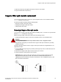
Copper or Fiber optic module replacement.....................................................95
Removing a Copper or fiber optic module...........................................95
Installing a new Copper or fiber optic module..................................... 96
Cabling a fiber optic module................................................................96
Tunable 10 GbE DWDM SFP+........................................................... 97
Fiber optic connector cleaning........................................................................ 97
Regulatory Statements............................................................................................................99
BSMI statement (Taiwan)................................................................................99
Canadian requirements...................................................................................99
China CC statement......................................................................................100
Europe and Australia (CISPR 22 Class A Warning)..................................... 100
FCC warning (US only)................................................................................. 101
Germany....................................................................................................... 101
KCC statement (Republic of Korea)..............................................................101
VCCI statement.............................................................................................101
Caution and Danger Notices..................................................................................................103
Cautions........................................................................................................ 103
Danger Notices............................................................................................. 110
Index.................................................................................................................................... 117
Brocade NetIron CES 2000 Series and NetIron CER 2000 Series Hardware Installation Guide
53-1003263-02
5
6
Brocade NetIron CES 2000 Series and NetIron CER 2000 Series Hardware Installation Guide
53-1003263-02
Preface
● Document conventions......................................................................................................7
● Brocade resources............................................................................................................ 9
● Contacting Brocade Technical Support.............................................................................9
● Document feedback........................................................................................................ 10
Document conventions
The document conventions describe text formatting conventions, command syntax conventions, and
important notice formats used in Brocade technical documentation.
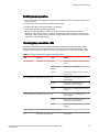
Text formatting conventions
Text formatting conventions such as boldface, italic, or Courier font may be used in the flow of the text
to highlight specific words or phrases.
Format
Description
bold text
Identifies command names
Identifies keywords and operands
Identifies the names of user-manipulated GUI elements
Identifies text to enter at the GUI
italic text
Identifies emphasis
Identifies variables and modifiers
Identifies paths and Internet addresses
Identifies document titles
Courier font
Identifies CLI output
Identifies command syntax examples
Command syntax conventions
Bold and italic text identify command syntax components. Delimiters and operators define groupings of
parameters and their logical relationships.
Convention
Description
bold text
Identifies command names, keywords, and command options.
italic text
Identifies a variable.
Brocade NetIron CES 2000 Series and NetIron CER 2000 Series Hardware Installation Guide
53-1003263-02
7
Notes, cautions, and warnings
Convention
Description
value
In Fibre Channel products, a fixed value provided as input to a command
option is printed in plain text, for example, --show WWN.
[]
Syntax components displayed within square brackets are optional.
Default responses to system prompts are enclosed in square brackets.
{x|y|z}
A choice of required parameters is enclosed in curly brackets separated by
vertical bars. You must select one of the options.
In Fibre Channel products, square brackets may be used instead for this
purpose.
x|y
A vertical bar separates mutually exclusive elements.
<>
Nonprinting characters, for example, passwords, are enclosed in angle
brackets.
...
Repeat the previous element, for example, member[member...].
\
Indicates a “soft” line break in command examples. If a backslash separates
two lines of a command input, enter the entire command at the prompt without
the backslash.
Notes, cautions, and warnings
Notes, cautions, and warning statements may be used in this document. They are listed in the order of
increasing severity of potential hazards.
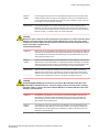
NOTE
A Note provides a tip, guidance, or advice, emphasizes important information, or provides a reference
to related information.
ATTENTION
An Attention statement indicates a stronger note, for example, to alert you when traffic might be
interrupted or the device might reboot.
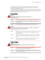
CAUTION
A Caution statement alerts you to situations that can be potentially hazardous to you or cause
damage to hardware, firmware, software, or data.
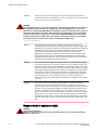
DANGER
A Danger statement indicates conditions or situations that can be potentially lethal or
extremely hazardous to you. Safety labels are also attached directly to products to warn of
these conditions or situations.
8
Brocade NetIron CES 2000 Series and NetIron CER 2000 Series Hardware Installation Guide
53-1003263-02
Brocade resources
Brocade resources
Visit the Brocade website to locate related documentation for your product and additional Brocade
resources.
You can download additional publications supporting your product at www.brocade.com. Select the
Brocade Products tab to locate your product, then click the Brocade product name or image to open the
individual product page. The user manuals are available in the resources module at the bottom of the
page under the Documentation category.
To get up-to-the-minute information on Brocade products and resources, go to MyBrocade. You can
register at no cost to obtain a user ID and password.
Release notes are available on MyBrocade under Product Downloads.
White papers, online demonstrations, and data sheets are available through the Brocade website.
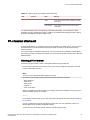
Contacting Brocade Technical Support
As a Brocade customer, you can contact Brocade Technical Support 24x7 online, by telephone, or by email. Brocade OEM customers contact their OEM/Solutions provider.
Brocade customers
For product support information and the latest information on contacting the Technical Assistance
Center, go to http://www.brocade.com/services-support/index.html.
If you have purchased Brocade product support directly from Brocade, use one of the following methods
to contact the Brocade Technical Assistance Center 24x7.
Online
Telephone
E-mail
Preferred method of contact for nonurgent issues:
Required for Sev 1-Critical and Sev
2-High issues:
[email protected]
• My Cases through MyBrocade
•
Continental US: 1-800-752-8061
• Software downloads and licensing •
tools
Europe, Middle East, Africa, and
Asia Pacific: +800-AT FIBREE
(+800 28 34 27 33)
• Knowledge Base
•
For areas unable to access toll
free number: +1-408-333-6061
•
Toll-free numbers are available in
many countries.
Please include:
•
Problem summary
•
Serial number
•
Installation details
•
Environment description
Brocade OEM customers
If you have purchased Brocade product support from a Brocade OEM/Solution Provider, contact your
OEM/Solution Provider for all of your product support needs.
• OEM/Solution Providers are trained and certified by Brocade to support Brocade® products.
• Brocade provides backline support for issues that cannot be resolved by the OEM/Solution Provider.
Brocade NetIron CES 2000 Series and NetIron CER 2000 Series Hardware Installation Guide
53-1003263-02
9
Document feedback
• Brocade Supplemental Support augments your existing OEM support contract, providing direct
access to Brocade expertise. For more information, contact Brocade or your OEM.
• For questions regarding service levels and response times, contact your OEM/Solution Provider.
Document feedback
To send feedback and report errors in the documentation you can use the feedback form posted with
the document or you can e-mail the documentation team.
Quality is our first concern at Brocade and we have made every effort to ensure the accuracy and
completeness of this document. However, if you find an error or an omission, or you think that a topic
needs further development, we want to hear from you. You can provide feedback in two ways:
• Through the online feedback form in the HTML documents posted on www.brocade.com.
• By sending your feedback to [email protected].
Provide the publication title, part number, and as much detail as possible, including the topic heading
and page number if applicable, as well as your suggestions for improvement.
10
Brocade NetIron CES 2000 Series and NetIron CER 2000 Series Hardware Installation Guide
53-1003263-02
About This Document
● Audience......................................................................................................................... 11
● Supported hardware and software.................................................................................. 11
● Notice to the reader.........................................................................................................12
● Related publications........................................................................................................13
Audience
This document is designed for system administrators with a working knowledge of Layer 2 and Layer 3
switching and routing.
If you are using a Brocade device, you should be familiar with the following protocols if applicable to
your network - IP, RIP, OSPF, BGP, ISIS, IGMP, PIM, MPLS, and VRRP.
Supported hardware and software
The following hardware platforms are supported by this release of this guide:
Brocade NetIron CES 2000 Series and NetIron CER 2000 Series Hardware Installation Guide
53-1003263-02
11
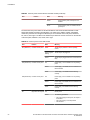
Supported software
TABLE 1 Supported devices
Brocade NetIron XMR Series
Brocade MLX Series
NetIron CES 2000 and NetIron CER 2000 Series
Brocade NetIron XMR 4000
Brocade MLX-4
Brocade NetIron CES 2024C
Brocade NetIron XMR 8000
Brocade MLX-8
Brocade NetIron CES 2024C-4X
Brocade NetIron XMR 16000
Brocade MLX-16
Brocade NetIron CER 2024C-4X-RT
Brocade NetIron XMR 32000
Brocade MLX-32
Brocade NetIron CES 2024F
Brocade MLXe-4
Brocade NetIron CES 2024F-4X
Brocade MLXe-8
Brocade NetIron CER 2024F-4X-RT
Brocade MLXe-16
Brocade NetIron CES 2048C
Brocade MLXe-32
Brocade NetIron CES 2048CX
Brocade NetIron CES 2048F
Brocade NetIron CES 2048FX
Brocade NetIron CER 2024C
Brocade NetIron CER-RT 2024C
Brocade NetIron CER 2024F
Brocade NetIron CER-RT 2024F
Brocade NetIron CER 2048C
Brocade NetIron CER-RT 2048C
Brocade NetIron CER 2048CX
Brocade NetIron CER-RT 2048CX
Brocade NetIron CER 2048F
Brocade NetIron CER-RT 2048F
Brocade NetIron CER 2048FX
Brocade NetIron CER-RT 2048FX
Supported software
Supporting Multi-Service IronWare R05.8.00.
Notice to the reader
This document may contain references to the trademarks of the following corporations. These
trademarks are the properties of their respective companies and corporations.
These references are made for informational purposes only.
12
Corporation
Referenced Trademarks and Products
Microsoft Corporation
Internet Explorer
Brocade NetIron CES 2000 Series and NetIron CER 2000 Series Hardware Installation Guide
53-1003263-02
Related publications
Corporation
Referenced Trademarks and Products
Mozilla Corporation
Mozilla Firefox
Oracle Corporation
Java Runtime Environment
Related publications
For the latest edition of these documents, which contain the most up-to-date information, see
Documentation at http://www.brocade.com/ethernetproducts
•
•
•
•
•
•
•
•
•
•
•
•
•
•
•
Multi-Service IronWare Administration Guide
Multi-Service IronWare Security Configuration Guide
Multi-Service IronWare Switching Configuration Guide
Multi-Service IronWare Routing Configuration Guide
Multi-Service IronWare Traffic Management Configuration Guide
Multi-Service IronWare Multicast Configuration Guide
Multi-Service IronWare Multiprotocol Label Switch (MPLS) Configuration Guide
Multi-Service IronWare Software Defined Networking (SDN) Guide
Brocade MLX Series and NetIron Family YANG Guide
Brocade MLX Series and NetIron XMR Series Diagnostic Reference
Unified IP MIB Reference
Multi-Service IronWare Software Upgrade Procedures for Brocade MLX Series routers
Brocade MLXe Series Installation Guide
Brocade MLX Series and Brocade NetIron XMR Installation Guide
Brocade NetIron CES 2000 Series and Brocade NetIron CER 2000 Series Hardware Installation
Guide
Brocade NetIron CES 2000 Series and NetIron CER 2000 Series Hardware Installation Guide
53-1003263-02
13
Related publications
14
Brocade NetIron CES 2000 Series and NetIron CER 2000 Series Hardware Installation Guide
53-1003263-02
Product Overview
● Introduction..................................................................................................................... 15
● Product overview.............................................................................................................20
● Software features............................................................................................................ 21
● Upgrade applications...................................................................................................... 21
● Hardware features...........................................................................................................22
Introduction
Network planners today have to expand and extend the range of services offered further into the edge
of the network. This requires extending the intelligence and high-touch processing capabilities to the
network edge-- whether in a metro network, a campus network or in a data center. The challenge at the
edge of the network is compounded by the need to flexibly define and easily manage customer services
in an intuitive manner. Further, of many rollouts. Whether deployed from a central office or from remote
huts, space is an important constraint for such providers.
In order to meet these challenges, the NetIron Carrier Ethernet Switch (CES) 2000 Series and NetIron
Carrier Ethernet Router (CER) 2000 Series were purpose-built to offer flexible, secure and advanced
processing capabilities in a compact form factor. The Brocade NetIron CES Series 2000 and Brocade
NetIron CER Series 2000 Series are compact 1 RU, multi-service edge or aggregation devices with a
powerful set of capabilities chosen to combine performance with rich functionality at the edge of the
network. The Brocade NetIron CES Series 2000 Series and Brocade NetIron CER Series 2000 Series
devices offer network planners a rich set of high-performance IPv4, Classic Layer 2, Provider Bridge
(PB) and Provider Backbone Bridge (PBB) functionalities in the same device. With these capabilities, a
diverse set of applications ranging from metro edge networks, ISPs, data centers, large enterprises,
government networks, and education or research can be addressed with the Brocade NetIron CES
Series 2000 Series and Brocade NetIron CER Series 2000 Series.
This guide includes procedures for installing the hardware and configuring essential, basic parameters
such as permanent passwords and IP addresses. The basic software configuration procedures show
how to perform tasks using the CLI. This guide also includes instructions for managing and maintaining
the NetIron Carrier Ethernet Switch (CES) and NetIron Carrier Ethernet Router (CER) hardware.
There are eight flavors to the NetIron Carrier Ethernet Switch (CES) 2000 Series:
• Brocade NetIron CES Series 2024C-4X -- accommodates 24-port 10/100/1000 RJ45 model with 4
combination 100/1000 Hybrid Fiber (HF) ports and 4x10G SFP+ uplinks
• Brocade NetIron CES Series 2024F-4X -- accommodates 24-port 100/1000 Hybrid Fiber (HF) model
with 4 combination 10/100/1000 RJ45 ports and 4x10G SFP+ uplinks
• Brocade NetIron CES Series 2024C -- accommodates 24-port 10/100/1000 RJ45 model with 4
combination 100/1000 Hybrid Fiber (HF) ports and an optional field upgradeable 2x10G uplink slot
• Brocade NetIron CES Series 2024F -- accommodates 24-port 100/1000 Hybrid Fiber (HF) model with
4 combination 10/100/1000 RJ45 ports and an optional field upgradeable 2x10G XFP uplink slot
• Brocade NetIron CES Series 2048C -- accommodates 48-port 10/100/1000 RJ45 model with 4
combination 100/1000 Hybrid Fiber (HF) ports
• Brocade NetIron CES Series 2048CX -- accommodates 48-port 10/100/1000 RJ45 model with
2x10G XFP uplink ports
Brocade NetIron CES 2000 Series and NetIron CER 2000 Series Hardware Installation Guide
53-1003263-02
15
Product Overview
• Brocade NetIron CES Series 2048F -- accommodates 48-port 100/1000 Hybrid Fiber (HF) model
• Brocade NetIron CES Series 2048FX -- accommodates 48-port 100/1000 Hybrid Fiber (HF) model
with 2x10G XFP uplink ports
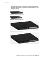
FIGURE 1 Brocade NetIron CES Series 2024C-4X
FIGURE 2 Brocade NetIron CES Series 2024F-4X
FIGURE 3 Brocade NetIron CES Series 2024C
FIGURE 4 Brocade NetIron CES Series 2024F
16
Brocade NetIron CES 2000 Series and NetIron CER 2000 Series Hardware Installation Guide
53-1003263-02
Product Overview
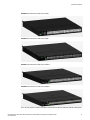
FIGURE 5 Brocade NetIron CES Series 2048C
FIGURE 6 Brocade NetIron CES Series 2048F
FIGURE 7 Brocade NetIron CES Series 2048CX
FIGURE 8 Brocade NetIron CES Series 2048FX
There are also fourteen models in the NetIron Carrier Ethernet Router (CER and CER-RT) 2000 Series:
Brocade NetIron CES 2000 Series and NetIron CER 2000 Series Hardware Installation Guide
53-1003263-02
17
Product Overview
• Brocade NetIron CER Series 2024C-4X -RT -- accommodates 24-port 10/100/1000 RJ45 model
with 4 combination 100/1000 Hybrid Fiber (HF) ports and 4x10G SFP+ uplinks. This device has the
ability to simultaneously store up to 1.5 million IPv4 routes and up to 256,000 IPv6 routes
• Brocade NetIron CER Series 2024F-4X-RT -- accommodates 24-port 100/1000 Hybrid Fiber (HF)
model with 4 combination 10/100/1000 RJ45 ports and 4x10G SFP+ uplinks. This device has the
ability to simultaneously store up to 1.5 million IPv4 routes and up to 256,000 IPv6 routes
• Brocade NetIron CER Series 2024C -- accommodates 24-port 10/100/1000 Copper RJ45 model
with 4 combination 100/1000 Hybrid Fiber (HF) ports and an optional field upgradeable 2x10G
uplink slot
• Brocade NetIron CER Series- RT 2024C -- accommodates 24-port 10/100/1000 Copper RJ45
model with 4 combination 100/1000 Hybrid Fiber (HF) ports and an optional field upgradeable
2x10G uplink slot. This device has the ability to simultaneously store up to 1.5 million IPv4 routes
and up to 256,000 IPv6 routes
• Brocade NetIron CER Series 2024F -- accommodates 24-port 100/1000 Hybrid Fiber (HF) model
with 4 combination 10/100/1000 RJ45 ports and an optional field upgradeable 2x10G XFP uplink
slot
• Brocade NetIron CER Series- RT 2024F -- accommodates 24-port 100/1000 Hybrid Fiber (HF)
model with 4 combination 10/100/1000 RJ45 ports and an optional field upgradeable 2x10G XFP
uplink slot. This device has the ability to simultaneously store up to 1.5 million IPv4 routes and up to
256,000 IPv6 routes
• Brocade NetIron CER Series 2048C -- accommodates 48-port 10/100/1000 Copper RJ45 model
with 4 combination 100/1000 Hybrid Fiber (HF) ports
• Brocade NetIron CER Series- RT 2048C -- accommodates 48-port 10/100/1000 Copper RJ45
model with 4 combination 100/1000 Hybrid Fiber (HF) ports. This device has the ability to
simultaneously store up to 1.5 million IPv4 routes and up to 256,000 IPv6 routes
• Brocade NetIron CER Series 2048F -- accommodates 48-port 100/1000 Hybrid Fiber (HF) model
• Brocade NetIron CER Series- RT 2048F -- accommodates 48-port 100/1000 Hybrid Fiber (HF)
model This device has the ability to simultaneously store up to 1.5 million IPv4 routes and up to
256,000 IPv6 routes
• Brocade NetIron CER Series 2048CX -- accommodates 48-port 10/100/1000 RJ45 model with
2x10G XFP uplink ports
• Brocade NetIron CER Series- RT2048CX -- accommodates 48-port 10/100/1000 RJ45 model with
2x10G XFP uplink ports. This device has the ability to simultaneously store up to 1.5 million IPv4
routes and up to 256,000 IPv6 routes
• Brocade NetIron CER Series 2048FX -- accommodates 48-port 100/1000 Hybrid Fiber (HF) model
with 2x10G XFP uplink ports
• Brocade NetIron CER Series- RT 2048FX -- accommodates 48-port 100/1000 Hybrid Fiber (HF)
model with 2x10G XFP uplink ports. This device has the ability to simultaneously store up to 1.5
million IPv4 routes and up to 256,000 IPv6 routes
FIGURE 9 Brocade NetIron CER Series 2024C-4X-RT
FIGURE 10 Brocade NetIron CER Series 2024F-4X-RT
18
Brocade NetIron CES 2000 Series and NetIron CER 2000 Series Hardware Installation Guide
53-1003263-02
Product Overview
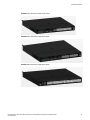
FIGURE 11 Brocade NetIron CER Series 2024C
FIGURE 12 Brocade NetIron CER Series 2024F
FIGURE 13 Brocade NetIron CER Series 2048C
Brocade NetIron CES 2000 Series and NetIron CER 2000 Series Hardware Installation Guide
53-1003263-02
19
Product overview
FIGURE 14 Brocade NetIron CER Series 2048F
FIGURE 15 Brocade NetIron CER Series 2048CX
FIGURE 16 Brocade NetIron CER Series 2048FX
Product overview
The Brocade NetIron CES Series 2000 Series is a compact 1 RU, multi-service edge or aggregation
switch with a powerful set of capabilities that combine performance with rich functionality at the
network edge. The Brocade NetIron CES Series 2000 Series switch offers network planners a broad
set of high performance IPv4, Classic Layer 2, Provider Bridge (PB) and Provider Backbone Bridge
(PBB) functionalities in the same device. With these capabilities, the Brocade NetIron CES Series
2000 Series addresses a diverse set of applications in metro edge networks, ISP networks, mobile
backhaul networks, data centers, large enterprises, government networks and education or research.
20
Brocade NetIron CES 2000 Series and NetIron CER 2000 Series Hardware Installation Guide
53-1003263-02
Software features
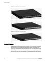
FIGURE 17 Brocade NetIron CES Series 2000 Series switch
The Brocade NetIron CER Series 2000 Series is a compact 1 RU, IP, MPLS, and multi-VRF enabled
metro router offering a broad set of capabilities including high performance IPv4 and IPv6 routing,
Advanced Layer 2, Multiprotocol Label Switching (MPLS), Provider Bridge (PB) and Provider Backbone
Bridge (PBB) functionalities in the same device. With these capabilities, the Brocade NetIron CER
Series 2000 Series addresses a diverse set of needs in service provider networks and enterprise
applications, as well as metro edge networks and small data centers.
FIGURE 18 Brocade NetIron CER Series 2000 Series router
Software features
Software features differ depending on the software package that is purchased with the device. The
BASE package on the Brocade NetIron CES Series 2000 devices support full Layer 2 Switching and
base Layer 3 (RIP and static routes). The Metro Edge Premium (ME_PREM) package support full Layer
2 Switching, base Layer 3 (RIP and static routes), Provider Bridges (IEEE 802.1ad), Provider Backbone
Bridges (IEEE 802.1ah), OSPF, ISIS, and Connectivity Fault Management (IEEE 802.1ag) and Service
OAM. The Layer 3 Premium (L3_PREM) packages support full Layer 2 Switching, base Layer 3 (RIP
and static routes), and full Layer 3 including BGP, ISIS and OSPF.
The BASE package on the Brocade NetIron CER Series 2000 devices support full Layer 2 Switching
and full Layer 3 (RIP, OSPF, ISIS, and BGP). It also includes virtual routing in non-MPLS environments
via Multi-VRF. The Advanced Services Premium (ADV_SVCS_PREM) package includes MPLS, Layer
2 VPNs using VPLS and VLLs, Provider Bridges (IEEE 802.1ad), Provider Backbone Bridges (IEEE
802.1ah), Connectivity Fault Management (IEEE 802.1ag) and Service OAM, along with Ethernet
Service Instance (ESI). The Brocade NetIron CER -RT features full MPLS capabilities as the original
Brocade NetIron CER, and has the ability to simultaneously store up to 1.5 million IPv4 routes and up to
256,000 IPv6 routes.
All Brocade NetIron CES Series 2000 and Brocade NetIron CER Series 2000 devices can be upgraded
to premium packages.
Upgrade applications
You can convert (upgrade) your Brocade NetIron CES Series 2000 Series device. Converting your
Brocade NetIron CES Series 2000 Series device allows you to run a software image that contains
additional capabilities available in premium packages.
To convert your Brocade NetIron CES Series and Brocade NetIron CER Series 2000 Series devices,
you need an upgrade kit. The kit includes a Dual Inline Package (DIP) key, Multi-Service IronWare
software, upgrade instructions, and other items. Alternatively, you can order an Brocade NetIron CES
Series or Brocade NetIron CER Series 2000 Series device with the premium software already installed.
For more information, refer to the Multi-Service IronWare Software Upgrade Guide .
Brocade NetIron CES 2000 Series and NetIron CER 2000 Series Hardware Installation Guide
53-1003263-02
21
Hardware features
TABLE 2 Upgrade kits
Brocade part number Description
NI-CES-2024-MEU
Metro Edge Premium upgrade for Brocade NetIron CES Series 2000 Series 24-port
models.
NI-CES-2024-L3U
L3 Premium upgrade for Brocade NetIron CES Series 2000 Series 24-port models.
NI-CES-2048-MEU
Metro Edge Premium upgrade for Brocade NetIron CES Series 2000 Series 48-port
models.
NI-CES-2048-L3U
L3 Premium upgrade for Brocade NetIron CES Series 2000 Series 48-port models.
NI-CER-2024-ADVU
Advanced Services Premium License for Brocade NetIron CER Series 24-port models.
NI-CER-2048-ADVU
Advanced Services Premium License for Brocade NetIron CER Series 48-port models.
Hardware features
This section describes the physical characteristics of the Brocade NetIron CES Series 2000 and
Brocade NetIron CER Series 2000 Series devices. For details about physical dimensions, power
supply specifications, and pinouts, refer to the Hardware features.
The following figures show the front panels of the various NetIron 2024 and 2048 devices.
NOTE
This is only a representative sample. For the exact model, look at the faceplate on the front of the
device. Both CER and CES devices have similar look and feel.
Brocade NetIron CES Series 2024C-4X
The Brocade NetIron CES Series 2024C-4X switch has twenty-four 10/100/1000 MbE RJ45 ports plus
four combination 100/ 1000 MbE SFP ports, 4-port 10 GbE SFP+ module, one DB9 serial
management interface port labeled Console, one 10/100/1000 MbE RJ45 out-of-band management
port, one resilient six-unit fan tray, and two AC power supply bays for 1+1 redundancy with one 500W
AC power supply included.
FIGURE 19 Brocade NetIron CES Series 2024C-4X device
22
1
10 GbE SFP+ ports
2
Four combination 100/1000 MbE SFP ports
3
Twenty-four 10/100/1000 MbE RJ45 ports
Brocade NetIron CES 2000 Series and NetIron CER 2000 Series Hardware Installation Guide
53-1003263-02
Brocade NetIron CES Series 2024F-4X
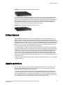
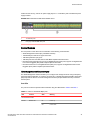
Brocade NetIron CES Series 2024F-4X
The Brocade NetIron CES Series 2024F-4X has twenty-four 100/1000 MbE SFP ports plus four
combination 10/100/1000 MbE RJ45 ports, 4-port 10 GbE SFP+ module, one DB9 serial management
interface port labeled Console, one 10/100/1000 MbE RJ45 out-of-band management port, one resilient
six-unit fan tray, and two AC power supply bays for 1+1 redundancy with one 500W AC power supply
included.
FIGURE 20 Brocade NetIron CES Series 2024F-4X device
1
10 GbE SFP+ ports
2
Four combination 10/100/1000 MbE RJ45 ports
3
Twenty-four 100/1000 MbE SFP ports
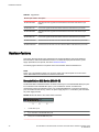
Brocade NetIron CES Series 2024C
The Brocade NetIron CES Series 2024C switch has twenty-four 10/100/1000 MbE RJ45 ports plus four
combination 100/ 1000 MbE SFP ports, one module slot for an optional field upgradable 2-port 10 GbE
XFP module, one DB9 serial management interface port labeled Console, one 10/100/1000 MbE RJ45
out-of-band management port, one resilient six-unit fan tray, and two AC power supply bays for 1+1
redundancy with one 500W AC power supply included.
FIGURE 21 Brocade NetIron CES Series 2024C device with the optional 2 ports of 10-G XFP uplink
1
Optional 10 GbE XFP ports
2
Four combination 100/1000 MbE SFP ports
3
Twenty-four 10/100/1000 MbE RJ45 ports
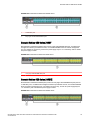
Brocade NetIron CES Series 2024F
The Brocade NetIron CES Series 2024F has twenty-four 100/1000 MbE SFP ports plus four
combination 10/100/1000 MbE RJ45 ports, one module slot for an optional field upgradable 2-port 10
GbE XFP module, one DB9 serial management interface port labeled Console, one 10/100/1000 MbE
Brocade NetIron CES 2000 Series and NetIron CER 2000 Series Hardware Installation Guide
53-1003263-02
23
Brocade NetIron CES Series 2048C
RJ45 out-of-band management port, one resilient six-unit fan tray, and two AC power supply bays for
1+1 redundancy with one 500W AC power supply included.
FIGURE 22 Brocade NetIron CES Series 2024F device
1
Four combination 10/100/1000 MbE RJ45 ports with support for optional 10Gbe XFP ports
2
Twenty-four 100/1000 MbE SFP ports
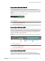
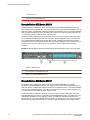
Brocade NetIron CES Series 2048C
Brocade NetIron CES Series 2048C (Copper) switch has forty-eight 10/100/1000 MbE RJ45 ports plus
four combination 100/ 1000 MbE SFP ports, one DB9 serial management interface port labeled
Console, one 10/100/1000 MbE RJ45 out-of-band management port, one resilient six-unit fan tray,
and two AC power supply bays for 1+1 redundancy with one 500W AC power supply included.
FIGURE 23 Brocade NetIron CES Series 2048C device
1
Four combination 100/1000 MbE SFP ports
2
Forty-eight 10/100/1000 MbE RJ45 ports
Brocade NetIron CES Series 2048CX
Brocade NetIron CES Series 2048CX (Copper) has forty-eight 10/100/1000 MbE RJ45 ports plus two
10 GbE XFP ports, one DB9 serial management interface port labeled Console, one 10/100/1000 MbE
RJ45 out-of-band management port, one resilient six-unit fan tray, and two AC power supply bays for
1+1 redundancy with one 500W AC power supply included.
24
Brocade NetIron CES 2000 Series and NetIron CER 2000 Series Hardware Installation Guide
53-1003263-02
Brocade NetIron CES Series 2048F
FIGURE 24 Brocade NetIron CES Series 2048CX device
1
10 GbE XFP ports
2
Forty-eight 10/100/1000 MbE RJ45 ports
Brocade NetIron CES Series 2048F
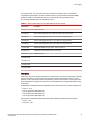
Brocade NetIron CES Series 2048F (Fiber) has forty-eight 100/1000 MbE SFP ports, one DB9 serial
management interface port labeled Console, one 10/100/1000 MbE RJ45 out-of-band management
port, one resilient six-unit fan tray, and two AC power supply bays for 1+1 redundancy with one 500W
AC power supply included.
FIGURE 25 Brocade NetIron CES Series 2048F device
1
Forty eight 100/1000 MbE SFP ports
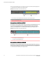
Brocade NetIron CES Series 2048FX
Brocade NetIron CES Series 2048FX (Fiber) switch has forty-eight 100/1000 MbE SFP ports plus two
10 GbE XFP ports, one DB9 serial management interface port labeled Console, one 10/100/1000 MbE
RJ45 out-of-band management port, one resilient six-unit fan tray, and two AC power supply bays for
1+1 redundancy with one 500W AC power supply included.
FIGURE 26 Brocade NetIron CES Series 2048FX device
Brocade NetIron CES 2000 Series and NetIron CER 2000 Series Hardware Installation Guide
53-1003263-02
25
Brocade NetIron CER Series 2024C
1
10 GbE XFP ports
2
Forty eight 100/1000 MbE SFP ports
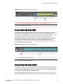
Brocade NetIron CER Series 2024C
The Brocade NetIron CER Series 2024C router has twenty-four 10/100/1000 MbE RJ45 ports plus
four combination 100/ 1000 MbE SFP ports, one module slot for an optional field upgradable 2-port 10
GbE XFP module, one DB9 serial management interface port labeled Console, one 10/100/1000 MbE
RJ45 out-of-band management port, one resilient six-unit fan tray, and two AC power supply bays for
1+1 redundancy with one 500W AC power supply included.
The Brocade NetIron CER Series-RT 2024C router has more memory to support 1.5M routes, twentyfour 10/100/1000 MbE RJ45 ports plus four combination 100/ 1000 MbE SFP ports, one module slot
for an optional field upgradable 2-port 10 GbE XFP module, one DB9 serial management interface
port labeled Console, one 10/100/1000 MbE RJ45 out-of-band management port, one resilient six-unit
fan tray, and two AC power supply bays for 1+1 redundancy with one 500W AC power supply
included.
FIGURE 27 Brocade NetIron CER Series 2024C device with the optional 2 ports of 10-G XFP uplink
1
Optional 10 GbE XFP ports
2
Four combination 100/1000 MbE SFP ports
3
Twenty-four 10/100/1000 MbE RJ45 ports
Brocade NetIron CER Series 2024F
The Brocade NetIron CER Series 2024F has twenty-four 100/1000 MbE SFP ports plus four
combination 10/100/1000 MbE RJ45 ports, one module slot for an optional field upgradable 2-port 10
GbE XFP module, one DB9 serial management interface port labeled Console, one 10/100/1000 MbE
RJ45 out-of-band management port, one resilient six-unit fan tray, and two AC power supply bays for
1+1 redundancy with one 500W AC power supply included.
The Brocade NetIron CER Series-RT 2024F has more memory to support 1.5M routes, twenty-four
100/1000 MbE SFP ports plus four combination 10/100/1000 MbE RJ45 ports, one module slot for an
optional field upgradable 2-port 10 GbE XFP module, one DB9 serial management interface port
labeled Console, one 10/100/1000 MbE RJ45 out-of-band management port, one resilient six-unit fan
tray, and two AC power supply bays for 1+1 redundancy with one 500W AC power supply included.
26
Brocade NetIron CES 2000 Series and NetIron CER 2000 Series Hardware Installation Guide
53-1003263-02
Brocade NetIron CER Series 2048C
FIGURE 28 Brocade NetIron CER Series 2024F device
1
Four combination 10/100/1000 MbE RJ45 ports with support for optional 10Gbe XFP ports
2
Twenty-four 100/1000 MbE SFP ports.
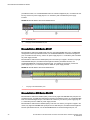
Brocade NetIron CER Series 2048C
Brocade NetIron CER Series 2048C (Copper) router has forty-eight 10/100/1000 MbE RJ45 ports plus
four combination 100/ 1000 MbE SFP ports, one DB9 serial management interface port labeled
Console, one 10/100/1000 MbE RJ45 out-of-band management port, one resilient six-unit fan tray, and
two AC power supply bays for 1+1 redundancy with one 500W AC power supply included.
Brocade NetIron CER Series-RT 2048C (Copper) router has more memory to support 1.5M routes,
forty-eight 10/100/1000 MbE RJ45 ports plus four combination 100/ 1000 MbE SFP ports, one DB9
serial management interface port labeled Console, one 10/100/1000 MbE RJ45 out-of-band
management port, one resilient six-unit fan tray, and two AC power supply bays for 1+1 redundancy
with one 500W AC power supply included.
FIGURE 29 Brocade NetIron CER Series 2048C device
1
Four combination 100/1000 MbE SFP ports
2
Forty-eight 10/100/1000 MbE RJ45 ports
Brocade NetIron CER Series 2048CX
Brocade NetIron CER Series 2048CX (Copper) has forty-eight 10/100/1000 MbE RJ45 ports plus two
10 GbE XFP ports, one DB9 serial management interface port labeled Console, one 10/100/1000 MbE
RJ45 out-of-band management port, one resilient six-unit fan tray, and two AC power supply bays for
1+1 redundancy with one 500W AC power supply included.
Brocade NetIron CER Series-RT 2048CX (Copper) has more memory to support 1.5M routes, fortyeight 10/100/1000 MbE RJ45 ports plus two 10 GbE XFP ports, one DB9 serial management interface
Brocade NetIron CES 2000 Series and NetIron CER 2000 Series Hardware Installation Guide
53-1003263-02
27
Brocade NetIron CER Series 2048F
port labeled Console, one 10/100/1000 MbE RJ45 out-of-band management port, one resilient six-unit
fan tray, and two AC power supply bays for 1+1 redundancy with one 500W AC power supply
included.
FIGURE 30 Brocade NetIron CER Series 2048CX device
1
10 GbE XFP ports
2
Forty-eight 10/100/1000 MbE RJ45 ports
Brocade NetIron CER Series 2048F
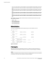
Brocade NetIron CER Series 2048F (Fiber) has forty-eight 100/1000 MbE SFP ports, one DB9 serial
management interface port labeled Console, one 10/100/1000 MbE RJ45 out-of-band management
port, one resilient six-unit fan tray, and two AC power supply bays for 1+1 redundancy with one 500W
AC power supply included.
Brocade NetIron CER Series-RT 2048F (Fiber) has more memory to support 1.5M routes, forty-eight
100/1000 MbE SFP ports, one DB9 serial management interface port labeled Console, one
10/100/1000 MbE RJ45 out-of-band management port, one resilient six-unit fan tray, and two AC
power supply bays for 1+1 redundancy with one 500W AC power supply included.
FIGURE 31 Brocade NetIron CER Series 2048F device
1
Forty eight 100/1000 MbE SFP ports
Brocade NetIron CER Series 2048FX
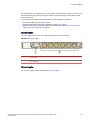
Brocade NetIron CER Series 2048FX (Fiber) router has forty-eight 100/1000 MbE SFP ports plus two
10 GbE XFP ports, one DB9 serial management interface port labeled Console, one 10/100/1000 MbE
RJ45 out-of-band management port, one resilient six-unit fan tray, and two AC power supply bays for
1+1 redundancy with one 500W AC power supply included.
Brocade NetIron CER Series-RT 2048FX (Fiber) router has more memory to support to support 1.5M
routes, forty-eight 100/1000 MbE SFP ports plus two 10 GbE XFP ports, one DB9 serial management
interface port labeled Console, one 10/100/1000 MbE RJ45 out-of-band management port, one
28
Brocade NetIron CES 2000 Series and NetIron CER 2000 Series Hardware Installation Guide
53-1003263-02
Control features
resilient six-unit fan tray, and two AC power supply bays for 1+1 redundancy with one 500W AC power
supply included.
FIGURE 32 Brocade NetIron CER Series 2048FX device
1
10 GbE XFP ports
2
Forty eight 100/1000 MbE SFP ports
Control features
The front panel on each device has a combination of the following control features:
•
•
•
•
•
Serial Management Interface (the port labeled Console)
10/100/1000 ports with RJ-45 copper connectors
100/1000 Hybrid Fiber (HF) ports
100/1000 ports with mini-GBIC slots for SFP MSA-compliant fiber transceivers
Each device that optionally has up to two 10-Gigabit Ethernet uplink ports, supports 10-Gigabit Small
Form Factor Pluggable (XFP) MSA-compliant optical transceivers
• Each device that has four 10-Gigabit Ethernet uplink ports, supports 10-Gigabit Small Form Factor
Pluggable (SFP+) MSA-compliant optical transceivers
Serial Management Interface (console port)
The Serial Management Interface enables you to configure and manage the device using a third-party
terminal emulation application on a directly connected PC. A straight-through EIA/TIA DB-9 serial cable
(M/F) ships with the device. The serial management interface (the port labeled Console) is located in
the front panel.
Port LEDs
The ports on the devices provide status information using the LEDs listed in Table 3 and Table 4 .
TABLE 3 LEDs for 10/100/1000 Mbps ports
LED
Position
State
Meaning
On
Link is up.
Off
Link is down.
10/100/1000 Port LEDs
Lnk/Act
Bottom Left
Brocade NetIron CES 2000 Series and NetIron CER 2000 Series Hardware Installation Guide
53-1003263-02
29
Product Overview
TABLE 3 LEDs for 10/100/1000 Mbps ports (Continued)
LED
Lnk/Act
Position
Bottom Right
State
Meaning
Blinking
Port is transmitting or receiving traffic
On
Link is up.
Off
Link is down.
Blinking
Port is transmitting or receiving traffic
NOTE
The LEDs are located beneath the port connector.
TABLE 4 LEDs for 10-Gbps Ethernet ports
LED
Port
State
Meaning
10-Gbps Port LEDs on devices with two 10-Gbps ports
Top
Bottom
Left hand port
Right hand port
On
The port is connected.
Off
No fiber port connection exists.
Blinking
Traffic is being transmitted and received on the fiber port
On
The port is connected.
Off
No fiber port connection exists.
Blinking
Traffic is being transmitted and received on the fiber port
10-Gbps Port LEDs on devices with four 10-Gbps ports
Top
Bottom
Left hand port
Right hand port
On
The port is connected.
Off
No fiber port connection exists.
Blinking
Traffic is being transmitted and received on the fiber port
On
The port is connected.
Off
No fiber port connection exists.
Blinking
Traffic is being transmitted and received on the fiber port
NOTE
The LEDs are located adjacent to the port connector.
30
Brocade NetIron CES 2000 Series and NetIron CER 2000 Series Hardware Installation Guide
53-1003263-02
Network interfaces
Network interfaces
This section describes the port types in the Brocade NetIron CES Series, Brocade NetIron CER Series
2000 series devices.
10/100/1000 Mbps ports
The 10/100/1000 ports on the device use auto-sensing and auto-negotiating to determine the speed (10
Mbps, 100 Mbps, or 1000 Mbps) and duplex mode (full-duplex or half-duplex) of the port at the other
end of the link and adjust port speed accordingly.
Combination ports
On devices with combination (combo) ports, one port out of each pair of copper and fiber ports can be
active at a time. Combo ports are numbered 1-4. For example, you can use either copper port 2 or fiber
port 2, but not both at the same time. You can use a combination of fiber and copper ports or all copper
or all fiber ports, as needed.
If you attach both the copper and fiber connectors for a port to the network, the fiber connectors take
precedence over the copper connectors. These ports support true media automatic detection, meaning
the device selects the fiber or copper connector based on link availability. If a fiber link cannot be
established, the device selects the copper media.
10-Gbps ports
The Brocade NetIron CES Series 2048C-4X, Brocade NetIron CES Series 2048F-4X, Brocade NetIron
CER Series 2048C-4X-RT, and the Brocade NetIron CER Series 2048F-4X-RT come with four 10Gigabit Ethernet ports installed. The four 10-Gigabit Ethernet uplink ports support 10-Gigabit Small
Form Factor Pluggable (SFP+) MSA-compliant optical transceivers
The Brocade NetIron CES Series 2048CX, Brocade NetIron CES Series 2048FX, Brocade NetIron CER
Series 2048CX, and the Brocade NetIron CER Series 2048FX come with two 10-Gigabit Ethernet ports
installed. A 24-port Brocade NetIron CES Series,Brocade NetIron CER Series has a slot to
accommodate a 2-port 10-Gigabit Ethernet module. If your 24-port device does not include a 10-GbE
module, you can optionally install one. Refer to 10-Gbps ports. The two 10-Gigabit Ethernet ports use
10-Gigabit Small Form Factor Pluggable (XFP) MSA-compliant transceivers.
Supported optics
100/1000 Ethernet Ports
The Ethernet Interface module contains 24 or 48 physical ports, through which you can connect your
device to other network devices at a speed of 100 Mbps or 1 Gbps.
Into a physical port, you must insert a fiber-optic transceiver provided by Brocade. The SFP-compliant
fiber-optic modules provide an optical transceiver or physical medium-dependent (PMD) interface for
fiber that can be used with the LAN physical layer (PHY)
The following 100 Mbps and 1 GbE optical transceivers are available from Brocade:
Brocade NetIron CES 2000 Series and NetIron CER 2000 Series Hardware Installation Guide
53-1003263-02
31
10 Gigabit Ethernet ports
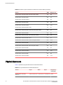
TABLE 5 SFP-compliant transceivers for the 100/1000 Ethernet interface module
Part number
Description
E1MG-TX
SFP Copper, RJ-45 connector
E1MG-SX
1000Base-SX SFP optic, multi-mode fiber, LC connector
E1MTG-SX
1000Base-SX SFP optic, multi-mode fiber, MTRJ connector
E1MG-SX2-1310
1310 1000Base-SX SFP optic multi-mode fiber, LC connector and support for distances
up to 2km
E1MG-LX
1000Base-LX SFP optic, single-mode fiber, LC connector
E1MG-LHA
1000Base-LHA SFP optic, single-mode fiber, LC connector
E1MG-LHB
1000Base-LHB SFP optic, single-mode fiber, LC connector, 150km Maximum Reach
E1MG-BXD
1000Base-BXD SFP optic single-mode fiber, 1490nm, LC connector. This optic can only
be connected to an E1MG-BXU
E1MG-CWDM80-1470 CWDM SFP optic, 80km, 1470nm, LC connector
E1MG-CWDM80-1490 CWDM SFP optic, 80Km, 1490nm, LC connector
E1MG-CWDM80-1510 CWDM SFP optic, 80Km, 1510nm, LC connector
E1MG-CWDM80-1530 CWDM SFP optic, 80Km, 1530nm, LC connector
E1MG-CWDM80-1550 CWDM SFP optic, 80Km, 1550nm, LC connector
E1MG-CWDM80-1570 CWDM SFP optic, 80Km, 1570nm, LC connector
E1MG-CWDM80-1590 CWDM SFP optic, 80Km, 1590nm, LC connector
E1MG-CWDM80-1610 CWDM SFP optic, 80Km, 1610nm, LC connector
E1MG-100FX
100Base-FX SFP optic multi-mode fiber, LC connector
E1MG-100BXU
100Base-BXU SFP optic single-mode fiber, 1310nm, LC connector. This optic can only
be connected to an E1MG-100BXD.
E1MG-100BXD
100Base-BXD SFP optic single-mode fiber, 1490nm, LC connector. This optic can only
be connected to an E1MG-100BXU.
E1MG-100FX-IR
100BaseFX-IR optic for SMF with LC connector. For distances up to 15nm.
E1MG-100FX-LR
100BaseFX-LR SFP optic for SMF with LC connector. For distances up to 40km.
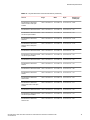
10 Gigabit Ethernet ports
A 10 Gigabit Ethernet module contains two or four physical ports, through which you can connect your
device to other network devices at a speed of 10 Gigabits.
32
Brocade NetIron CES 2000 Series and NetIron CER 2000 Series Hardware Installation Guide
53-1003263-02
Port regions
Into a physical port, you must insert a fiber-optic transceiver provided by device. The XFP/SFP+compliant fiber-optic modules provide an optical transceiver or physical medium-dependent (PMD)
interface for single or multi-mode fiber that can be used with the LAN physical layer (PHY).
The following 10 Gigabit optics are available from device.
TABLE 6 MSA-compliant Optics for the 10 GbE Ethernet interface module
Part number
Description
Devices with up to two 10GbE ports (XFP)
10G-XFP-SR
850nm serial pluggable XFP optic, target range 300m over multi-mode fiber
10G-XFP-LR
1310nm serial pluggable XFP optic for up to 10km over single-mode fiber
10G-XFP-ER
1550nm serial pluggable XFP optic for up to 40km over single-mode fiber
10G-XFP-ZR
1550nm serial pluggable XFP optic for up to 80km over single-mode fiber
10G-XFP-ZRD
10GBase-ZR DWDM, XFP optic, 80km, 1530.33 to 1561.42
10G-XFP-CX4
10-Base-CX4, XFP transceiver, 15km, CX connector
Devices with up to four 10GbE ports (SFP+)
10G-SFPlus-SR
10G-SFPlus-LR
10G-SFPlus-ZR
10G-SFPlus-ZRD
Port regions
Ports on the devices are grouped into regions. For a few features, such as port monitoring and unknown
unicast configurations, you will need to know the region to which a port belongs. However, for most
features, a port’s region does not affect configuration or operation of the feature. If a port’s region does
affect configuration or operation of a feature, it is noted and described in the appropriate feature section
of this guide.
Brocade NetIron CES Series 2024 and CER 2024 devices with 24 ports have 2 optional 10-GbE ports:
•
•
•
•
•
Ports 1/1 - 1/24
Port 2/1 (optional 10-GbE uplink port)
Port 2/2 (optional 10-GbE uplink port)
Port 2/3 (optional 10-GbE uplink port)
Port 2/4 (optional 10-GbE uplink port)
Brocade NetIron CES Series 2048 and Brocade NetIron CER Series 2048 devices with 48 ports:
• Ports 1/1 -1/24
• Ports 1/25 - 1/48
Brocade NetIron CES 2000 Series and NetIron CER 2000 Series Hardware Installation Guide
53-1003263-02
33
Network interfaces
• Port 2/1 (10-GbE uplink port on Brocade NetIron CES Series 2048CX, Brocade NetIron CES Series
2048FX, Brocade NetIron CER Series 2048CX, and Brocade NetIron CER Series 2048FX models
only)
• Port 2/2 (10-GbE uplink port on Brocade NetIron CES Series 2048CX, Brocade NetIron CES Series
2048FX, Brocade NetIron CER Series 2048CX, and Brocade NetIron CER Series 2048FX models
only)
• Port 2/3 (10-GbE uplink port on Brocade NetIron CES Series 2048CX, Brocade NetIron CES Series
2048FX, Brocade NetIron CER Series 2048CX, and Brocade NetIron CER Series 2048FX models
only)
• Port 2/4 (10-GbE uplink port on Brocade NetIron CES Series 2048CX, Brocade NetIron CES Series
2048FX, Brocade NetIron CER Series 2048CX, and Brocade NetIron CER Series 2048FX models
only)
Brocade NetIron CES Series 2024x and Brocade NetIron CER Series 2024x devices with 24 ports
have 2 optional 10-G ports:
•
•
•
•
•
Ports 1/1 -1/24
Port 2/1 (10G uplink port)
Port 2/2 (10G uplink port)
Port 2/3 (10G uplink port)
Port 2/4 (10G uplink port)
Network interfaces
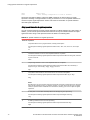
The output of the show media command displays the type of media installed in the ports.
device# show media
Port 1/1:
Type : Copper
Vendor:
Unknown,
Part# :
Unknown,
Port 1/2:
Type : Copper
Vendor:
Unknown,
Part# :
Unknown,
Port 1/24:
Type : Copper
Vendor:
,
Part# :
Unknown,
Port 2/1:
Type : 10GBASE-SR/SW (XFP)
Vendor:
FOUNDRY NETWORKS,
Part# :
FTLX8511D3-F1
,
Port 2/2:
Type : 10GBASE-SR/SW (XFP)
Vendor:
FOUNDRY NETWORKS,
Part# :
TRF2000EN-LF251 ,
All show media done
Version:
Serial#:
Unknown
Unknown
Version:
Serial#:
Unknown
Unknown
Version:
Serial#:
Unknown
Unknown
Version:
Serial#:
KCP02X8
Version:
Serial#:
T07J23170
00
02
Syntax: show media
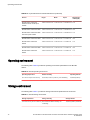
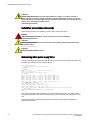
Power supplies
Each device comes with one alternating-current (AC) or one direct-current (DC) power supply. All
models have two power supply slots, enabling you to install a second power supply for redundancy.
NOTE
Changes or modifications made to this device that are not expressly approved by the party responsible
for compliance could void the user's authority to operate the equipment.
34
Brocade NetIron CES 2000 Series and NetIron CER 2000 Series Hardware Installation Guide
53-1003263-02
AC power supplies
The power supplies can be swapped in or out of the device while the device is running. You can remove
and insert a power supply without opening the chassis. The remaining supply provides enough power
for the entire system.
The following sections provide further details about the power supplies for the devices:
• Power status LEDs are listed in Power supplies.
• Hardware specifications for the power supplies are listed in Power supplies.
• Redundant power supplies and power supply failure information is listed in About redundant power
supplies and power supply failure on page 36.
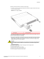
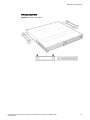
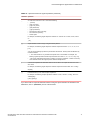
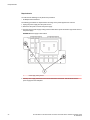
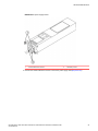
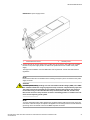
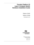
AC power supplies
AC power supplies shows a rear view of a device containing one AC power supply.
FIGURE 33 AC Power Supply
1
Power supply
2
Six cooling fans
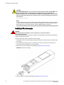
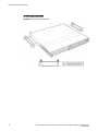
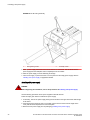
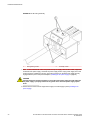
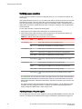
DC power supplies
The DC power supply is shown in the diagram DC power supplies.
Brocade NetIron CES 2000 Series and NetIron CER 2000 Series Hardware Installation Guide
53-1003263-02
35
About redundant power supplies and power supply failure
FIGURE 34 DC Power Supply
About redundant power supplies and power supply failure
A device with redundant power supplies can maintain full operation when one power supply fails.
Power supply failure can be a failure of the supply itself or the power grid connected to the power
supply.
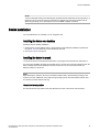
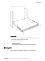
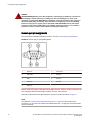
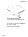
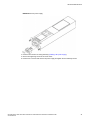
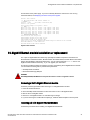
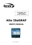
Cooling system and fans
This section describes the fans in the devices with 6 fans.
Cooling system and fans shows the cooling fans.
FIGURE 35 Cooling Fans
1
Six cooling fans
The device cooling fans use pull configuration to move the air from the front to the back of the device.
36
Brocade NetIron CES 2000 Series and NetIron CER 2000 Series Hardware Installation Guide
53-1003263-02
Product Overview
NOTE
Brocade NetIron CES/CER-4X-RT supports the XNI-CE-2000-FAN pre-installed or as a spare. All other
models support the NI-CE-2000-FAN.
The fans in the devices include six four-speed fans that operate at low speed, medium speed, mediumhigh speed, and high speed based on the ambient temperature and configured or default temperature
thresholds. All fans operate simultaneously at the same speed. If a single fan fails within the assembly,
the fan tray should be replaced. The fan tray is hot swappable and the mean time to recover (MTTR) is
one minute.
The system uses a default or configured temperature threshold associated with it to determine at which
speed the fan should operate.
Brocade NetIron CES 2000 Series and NetIron CER 2000 Series Hardware Installation Guide
53-1003263-02
37
Cooling system and fans
38
Brocade NetIron CES 2000 Series and NetIron CER 2000 Series Hardware Installation Guide
53-1003263-02
Connecting to a Network Device
● Password assignment..................................................................................................... 39
● IP address configuration................................................................................................. 40
● Management port function overview............................................................................... 43
● Device connection...........................................................................................................43
Password assignment
DANGER
The procedures in this manual are for qualified service personnel.
By default, the device’s CLI is not protected by passwords. To secure CLI access, Brocade strongly
recommends assigning passwords.
The CLI contains the following access levels:
• Privileged EXEC - This level is also called the Enable level and can be secured by a password. You
can perform tasks such as manage files on the management module’s flash memory or a PCMCIA
flash card in the management module’s slots 1 or 2, save the system configuration to flash memory,
and clear caches at this level.
• CONFIG - The configuration level. This level lets you configure the system’s IP address and
configure routing features. To access the CONFIG mode, you must already be logged into the
Privileged level of the EXEC mode.
NOTE
You can assign passwords using the Brocade Network Advisor if an Enable password for a Super
User is already configured on the device.
You can set the following levels of Enable passwords:
• Super User - Allows complete read-and-write access to the system. This is generally for system
administrators and is the only password level that allows you to configure passwords.
NOTE
You must set a super user password before you can set other types of passwords.
• Port Configuration - Allows read-and-write access for specific ports but not for global (system-wide)
parameters.
• Read Only - Allows access to the Privileged EXEC mode and CONFIG mode but only with read
access.
Follow the steps given below to set passwords.
Brocade NetIron CES 2000 Series and NetIron CER 2000 Series Hardware Installation Guide
53-1003263-02
39
IP address configuration
1. At the opening CLI prompt, enter the following command to change to the Privileged level of the
EXEC mode.
device> enable
device#
2. Access the CONFIG level of the CLI by entering the following command.
device# configure terminal
device(config)#
3. Enter the following command to set the super-user password.
device(config)#
enable super-user-password <text>
NOTE
You must set the super-user password before you can set other types of passwords.
4. Enter the following commands to set the port configuration and read-only passwords.
device(config)#
device(config)#
enable port-config-password <text>
enable read-only-password <text>
NOTE
If you forget your super-user password, see the Release Notes.
Syntax: enable super-user-password | read-only-password | port-config-password text
Passwords can be up to 48 characters long.
IP address configuration
The devices implement separate data and control planes. This architecture affects how you assign IP
addresses. Table 7 outlines the interfaces to which you can assign IP addresses.
In this table, "in band" refers to an interface over which user packets are routed, while "out of band"
refers to an interface over which control packets related to system management are forwarded.
TABLE 7 Assigning IP addresses
Interface
Associated physical port
Out of band/In band
Management interface
Ethernet 10/100/1000 port on active
management module
Out of band
Any interface over which user packets are
routed
Any interface module port
In band
Any virtual interface over which user packets
are routed
Any interface port
In band
Loopback interface
-
In band
This section describes the following:
40
Brocade NetIron CES 2000 Series and NetIron CER 2000 Series Hardware Installation Guide
53-1003263-02
Support of sub-net masks
• Support of sub-net masks
• How to assign an IP address to a management interface
• How to assign an IP address to an interface or virtual interface over which user packets are routed
Support of sub-net masks
The devices support both classical IP network masks (Class A, B, and C sub-net masks, and so on) and
Classless Interdomain Routing (CIDR) network prefix masks.
The following sub-net masks are supported by the devices:
• To enter a classical network mask, enter the mask in IP address format. For example, enter
"209.157.22.99 255.255.255.0" for an IP address with a Class-C sub-net mask.
• To enter a prefix number for a network mask, enter a forward slash (/) and the number of bits in the
mask immediately after the IP address. For example, enter "209.157.22.99/24" for an IP address that
has a network mask with 24 significant ("mask") bits.
Assigning an IP address to a management interface
Instead of assigning a global IP address to the device for system management purposes, you now
assign an IP address to the management interface. The IP address is assigned to the active
management module port. If the active management module becomes unavailable and the redundant
module becomes the active module, the IP address is assigned to the new active management module
port.
For example, to assign the IP address 10.0.1.1 to the management interface, do the following.
1. At the opening CLI prompt, enter enable.
device> enable
2. Enter the following command at the Privileged EXEC level prompt (for example, Brocade# ), then
press Enter. This command erases the factory test configuration if still present.
device# erase startup-config
CAUTION
Use the erase startup-config command only for new systems. If you enter this command on a
system you have already configured, the command erases the configuration. If you
accidentally do erase the configuration on a configured system, enter the write memory
command to save the running configuration to the startup-config file.
3. Access the configuration level of the CLI by entering the following command.
device# configure terminal
device(config)#
4. Configure the IP address and mask for the management interface by entering the following
commands.
device(config)# interface management 1
device(config-if-mgmt-1)# ip address 10.0.1.1 255.255.255.0
Syntax: enable [ password ]
Syntax: configure terminal
Syntax: interface management 1
Syntax: [no] ip address ip-addrip-mask
or
Brocade NetIron CES 2000 Series and NetIron CER 2000 Series Hardware Installation Guide
53-1003263-02
41
Assigning an IP address to an interface, virtual interface, or loopback
Syntax: [no] ip address ip-addr/mask-bits
Assigning an IP address to an interface, virtual interface, or loopback
As you have done with other devices, you must assign an IP address to each interface and virtual
interface over which user packets are routed. You can also assign an IP address to a loopback
interface, which is generally used for testing and diagnostic purposes.
You must use the serial connection to assign the first IP address. For subsequent addresses, you also
can use the CLI through Telnet. You can use Brocade Network Advisor to assign IP addresses to
virtual routing interfaces only.
By default, you can configure up to 24 IP interfaces on each interface, virtual interface, and loopback
interface.
For example, to assign the IP address 192.22.3.44 and sub-net mask 255.255.255.0 to Ethernet
interface 1/1, do the following.
1. At the opening CLI prompt, enter enable.
device> enable
2. Enter the following command at the Privileged EXEC level prompt, then press Enter. This command
erases the factory test configuration if still present.
device# erase startup-config
CAUTION
Use the erase startup-config command only for new systems. If you enter this command on
a system you have already configured, the command erases the configuration. If you
accidentally do erase the configuration on a configured system, enter the write memory
command to save the running configuration to the startup-config file.
3. Access the configuration level of the CLI by entering the following command.
device# configure terminal
device(config)#
4. Configure the IP address and sub-net mask for Ethernet interface 1/1 by entering the following
commands.
device(config)# interface ethernet 1/1
device(config-if-e10000-1/1)# ip address 192.22.3.44 255.255.255.0
Syntax: enable [ password ]
Syntax: configure terminal
Syntax: [no] ip address ip-addrip-mask [ secondary ]
or
Syntax: [no] ip address ip-addr/mask-bits [ secondary ]
Use the secondary parameter if you have already configured an IP address within the same sub-net
on the interface.
42
Brocade NetIron CES 2000 Series and NetIron CER 2000 Series Hardware Installation Guide
53-1003263-02
Enabling and disabling the interfaces
Enabling and disabling the interfaces
By default, all interfaces are disabled. To enable an interface, you must enter the enable command at
the appropriate interface configuration level of the CLI. For example, to enable the management
interface, enter the enable command at the management interface configuration level of the CLI.
device(config-if-mgmt-1)# enable
Syntax: enable
You can disable each of these interfaces using the disable command at the appropriate interface
configuration level of the CLI. For example, to disable the management port, enter the disable
command at the management interface configuration level of the CLI.
device(config-if-mgmt-1)# disable
Syntax: disable
NOTE
For security reasons, by default, the telnet server is disabled on the devices. To enable the telnet server
and allow access through telnet to the device from an external host, execute the
following.device(config)# telnet server
Management port function overview
You must be aware of how the system’s management port functions as described in the following:
• The management port allows you to configure, monitor, and manage the system only. As a result,
this port has the same limited functionality as an IP host port.
• You cannot enable and run routing protocols on the management port.
• The management port supports static routes and directly connected routes, which are installed in the
management module’s routing table. However, these routes are not installed in the interface
module’s routing table. Therefore, the interface modules are not aware of the management port’s
static or directly connected routes.
• If you configure the redistribution of directly connected or static routes for a particular routing
protocol, the routing protocol will redistribute directly connected or static routes associated with the
interface module ports but not those associated with the management port.
To display configuration information and statistics about the management port, you can enter the show
interface management 1 command at any CLI level.
Device connection
You can connect a Brocade device to another Ethernet network device. The Brocade devices support
connections to other vendors’ as well as Brocade network devices.
To connect a Brocade device to another network device, you must do the following:
• Install the fiber-optic modules if required
• Cable the modules with either copper cable or fiber optic cable as required
Brocade NetIron CES 2000 Series and NetIron CER 2000 Series Hardware Installation Guide
53-1003263-02
43
Connecting to a Network Device
For information on installing fiber-optic modules see Device connection.
For information on cabling a fiber-optic module, see Device connection.
For information on cleaning a fiber-optic module, see Device connection.
44
Brocade NetIron CES 2000 Series and NetIron CER 2000 Series Hardware Installation Guide
53-1003263-02
Installation
● System unpacking...........................................................................................................45
● Summary of installation tasks......................................................................................... 46
● Installation precautions................................................................................................... 47
● Installation site preparation............................................................................................. 49
● Redundant power supply installation.............................................................................. 50
● Device installation........................................................................................................... 55
● System power................................................................................................................. 59
● Operation verification...................................................................................................... 60
● PC or terminal attachment.............................................................................................. 63
System unpacking
DANGER
The procedures in this manual are for qualified service personnel.
The Brocade systems ship with all of the following items. Please review the list below and verify the
contents. If any items are missing, please contact the place of purchase.
Package contents
The package contains the following:
• Brocade NetIron CES Series 2000 or Brocade NetIron CER Series 2000 series device
• 115V AC power cable (for AC sourced devices)
General requirements
To manage the system, you need the following items for serial connection to the router:
• A management station, such as a PC running a terminal emulation application.
• A straight-through EIA/TIA DB-9 serial cable (F/F). The serial cable can be ordered separately from
Brocade.If you prefer to build your own cable, refer to the pinout information in General requirements.
You use the serial connection to perform basic configuration tasks including assigning an IP address
and network mask to the system. This information is required for managing the system using Brocade
Network Advisor or using the CLI through Telnet.
CAUTION
To prevent damage to the chassis and components, never attempt to lift the chassis using the
fan or power supply handles. These handles were not designed to support the weight of the
chassis.
Brocade NetIron CES 2000 Series and NetIron CER 2000 Series Hardware Installation Guide
53-1003263-02
45
Summary of installation tasks
CAUTION
Before plugging a cable into to any port, be sure to discharge the voltage stored on the cable
by touching the electrical contacts to ground surface.
Summary of installation tasks
Follow the steps listed below to install your Brocade device. Details for each of the steps highlighted
below are provided in this chapter and in the following chapter.
TABLE 8 Summary of installation tasks
46
Task number Task
Where to find more
information
1
Ensure that the physical environment that will host the device has
the proper cabling and ventilation.
Installation site preparation
on page 49
2
Optionally insert a second or redundant power supply. If you need
to install a power supply, it may be easier to install it before
mounting the device, although the power supplies are "hot
swappable", and can be installed or removed after the device is
mounted and powered-on.
Redundant power supply
installation on page 50
3
Install the Brocade device in an equipment rack.
Device installation on page
55
4
Once the device is physically installed, plug the device into a
nearby power source that adheres to the regulatory requirements
outlined in this manual.
System power on page 59
5
Verify that the system LEDs are registering the proper LED state
after power-on of the system.
Operation verification on
page 60
6
Attach a terminal or PC to the device. This will enable you to
configure the device through the Command Line Interface (CLI).
PC or terminal attachment on
page 63
7
No default password is assigned to the CLI. For additional access
security, assign a password.
Summary of installation tasks
8
Before connecting to the device, you need to configure an
Summary of installation tasks
interface IP address to the subnet on which it will be located. Initial
IP address configuration is performed using the CLI with a direct
serial connection. Subsequent IP address configuration can be
performed using the command line interface.
9
Once you power on the device and assign IP addresses, the
system is ready to accept network connections.
Summary of installation tasks
10
Secure access to the device.
Multi-Service IronWare
Security Guide
Brocade NetIron CES 2000 Series and NetIron CER 2000 Series Hardware Installation Guide
53-1003263-02
Installation precautions
Installation precautions
Follow these precautions when installing the unit.
DANGER
Risk of explosion if battery is replaced by an incorrect type. Dispose of used batteries according
to the instructions.
DANGER
All fiber-optic interfaces use Class 1 lasers.
CAUTION
Do not install the device in an environment where the operating ambient temperature might
exceed 40°C (104°F).
CAUTION
Make sure the airflow around the front, sides, and back of the device is not restricted.
CAUTION
Never leave tools inside the chassis.
Lifting precautions
DANGER
Make sure the rack housing the device is adequately secured to prevent it from becoming
unstable or falling over.
DANGER
Mount the devices you install in a rack as low as possible. Place the heaviest device at the
bottom and progressively place lighter devices above.
CAUTION
To prevent damage to the chassis and components, never attempt to lift the chassis using the
fan or power supply handles. These handles were not designed to support the weight of the
chassis.
Power precautions
CAUTION
Use a separate branch circuit for each power cord, which provides redundancy in case one of
the circuits fails.
Brocade NetIron CES 2000 Series and NetIron CER 2000 Series Hardware Installation Guide
53-1003263-02
47
Installation
CAUTION
Ensure that the device does not overload the power circuits, wiring, and over-current
protection. To determine the possibility of overloading the supply circuits, add the ampere
(amp) ratings of all devices installed on the same circuit as the device. Compare this total with
the rating limit for the circuit. The maximum ampere ratings are usually printed on the devices
near the input power connectors.
CAUTION
Carefully follow the mechanical guides on each side of the power supply slot and make sure
the power supply is properly inserted in the guides. Never insert the power supply upside
down.
NOTE
Power supplies are hot swappable.
CAUTION
Remove the power cord from a power supply before you install it in or remove it from the
device. Otherwise, the power supply or the device could be damaged as a result. (The device
can be running while a power supply is being installed or removed, but the power supply itself
should not be connected to a power source.)
CAUTION
The power supply is designed exclusively for use with the Brocade NetIron CES Series and
Brocade NetIron CER Series devices. The power supply produces extensive power. Installing
the power supply in a device other than a NetIron CES Series or NetIron CER Series will cause
damage to your equipment.
DANGER
Disconnect the power cord from all power sources to completely remove power from the
device.
DANGER
Make sure to choose the appropriate circuit device depending on the number of AC power
supplies installed in the chassis. The minimum current draw for the system is one AC power
supply.
DANGER
Make sure that the power source circuits are properly grounded, then use the power cord
supplied with the device to connect it to the power source.
DANGER
If the installation requires a different power cord than the one supplied with the device, make
sure you use a power cord displaying the mark of the safety agency that defines the
regulations for power cords in your country. The mark is your assurance that the power cord
can be used safely with the device.
48
Brocade NetIron CES 2000 Series and NetIron CER 2000 Series Hardware Installation Guide
53-1003263-02
Installation site preparation
CAUTION
All devices with DC power supplies are intended for installation in restricted access areas only.
A restricted access area is where access can be gained only by service personnel through the
use of a special tool, lock and key, or other means of security, and is controlled by the authority
responsible for the location.
CAUTION
For the DC input circuit, (DC power supply part number RPS9-DC), make sure there is a 20-amp
circuit breaker, minimum -48VDC, double pole, on the input to the terminal block. The input
wiring for connection to the product should be copper wire, 12 AWG, marked VW-1, and rated 90
degrees Celsius.
CAUTION
For a DC system, use a grounding wire of at least 6 American Wire Gauge (AWG). The 6 AWG
wire should be attached to an agency-approved crimp connector crimped with the proper tool.
The crimp connector should allow for securement to both ground screws on the enclosure. For
the Ground lug, use UL listed Panduit crimp connector, P/N LCD6-10A, and two 10-32, PPH,
screws to secure crimp connector to chassis. Grounding position is located on the side of the
chassis adjacent ground symbol.
Installation site preparation
Cabling infrastructure
Ensure that the proper cabling is installed in the site. Refer to Cabling infrastructure or
www.brocade.com for a summary of supported cabling types and their specifications.
DANGER
The intra-building port or ports of the equipment or subassembly is suitable for connection to
intra-building or unexposed wiring or cabling only. The intra-building port or ports of the
equipment or subassembly MUST NOT be metallically connected to interfaces that connect to
the outside plant (OSP) or its wiring. These interfaces are designed for use as intra-building
interfaces only (Type 2 or Type 4 ports as described in GR-1089-CORE, Issue 5) and require
isolation from the exposed OSP cabling. The addition of Primary Protectors is not sufficient
protection in order to connect these interfaces metallically to OSP wiring.
Installation location
Before installing the device, plan its location and orientation relative to other devices and equipment.
Allow at least 3 in. of space at the front of the device for the twisted-pair, fiber-optic, and power cabling.
Also, allow a minimum of 3 in. of space between the sides and the back of the device and walls or other
obstructions.
A Brocade device is suitable for installation in Network Telecommunications facilities and locations
where the NEC (National Electric Code) apply.
The device must be installed in a restricted access location, either a Central Office or customerpremises equipment location.
Brocade NetIron CES 2000 Series and NetIron CER 2000 Series Hardware Installation Guide
53-1003263-02
49
Redundant power supply installation
Redundant power supply installation
The Brocade device ships with one alternating-current (AC) power supply or direct-current (DC) power
supply. All models have two power supply slots, enabling you to install a second power supply for
redundancy. If desired, you can install a second supply for redundancy.
CAUTION
Changes or modifications made to this device that are not expressly approved by the party
responsible for compliance could void the user's authority to operate the equipment.
If you need to install a redundant power supply, it may be easier to install it before mounting the
device, although the power supplies are "hot swappable" and can be installed or removed after the
device is mounted and powered on.
This section provides the following procedures:
• Installing a redundant AC power supply - Installing an AC power supply on page 50
• Installing a redundant DC power supply - Installing a DC power supply on page 52
Installing an AC power supply
DANGER
Before beginning the installation, see the precautions in “Power precautions.”
FIGURE 36 Use the following procedures for AC power supplies in Brocade NetIron CES Series,
Brocade NetIron CER Series 2000 series devices.
50
Brocade NetIron CES 2000 Series and NetIron CER 2000 Series Hardware Installation Guide
53-1003263-02
Installation
Follow the procedure given below to install an AC power supply.
1. If necessary, remove the power supply locking screws located in the upper left and the bottom right
of the device (illustrated below).
FIGURE 37 Power supply installation
1
Power supply
2
Grounding terminals
2. If the empty power supply bay has a cover plate, remove the two screws near the edges of the cover
plate to unlock the plate, then remove the plate.
3. Remove the power supply from its packaging.
4. With one hand, hold the bar on the front panel of the power supply. With the other hand, support the
underside of the power supply, and insert the power supply into the empty power supply slot. Press
until the supply is completely in the slot, so that the connectors on the back of the supply are fully
engaged with the pins on the power backplane.
CAUTION
Carefully follow the mechanical guides on each side of the power supply slot and make sure
the power supply is properly inserted in the guides. Never insert the power supply upside
down.
5. Secure the two screws near the edges of the supply to lock the supply in place.
6. Lift the AC cord retainer clip.
7. Connect the power cord to the power supply.
8. Snap the AC cord retainer clip over the power cord.
9. Connect the plug end of the power cord into outlet.
Brocade NetIron CES 2000 Series and NetIron CER 2000 Series Hardware Installation Guide
53-1003263-02
51
Installing a DC power supply
CAUTION
For a Brocade AC system, use a ground wire of at least 6 American Wire Gauge (AWG). The
ground wire should have an agency-approved crimped connector (provided with the
chassis) attached to one end, with the other end attached to building ground. The connector
must be crimped with the proper tool, allowing it to be connected to both ground screws on
the enclosure.
NOTE
To insure adequate bonding when attaching the provided Panduit LCD6-10AF two-hole ground lug,
a minimum of 20 inch pounds of torque is required to be applied to the mounting hardware used to
attach the ground lug. Use a star washer to ensure an NEBS compliant connection.
Installing a DC power supply
DANGER
Before beginning the installation, see the precautions in “Power precautions.”
Use the following procedures for DC power supplies in Brocade NetIron CES Series, Brocade NetIron
CER Series 2000 series devices.
Follow the steps given below to install an DC power supply.
1. If necessary, remove the power supply locking screws located in the upper left and the bottom right
of the device.
2. If the empty power supply bay has a cover plate, remove the two screws near the edges of the
cover plate to unlock the plate, then remove the plate.
3. Remove the DC power supply from its packaging (Installing a DC power supply).
FIGURE 38 The DC power supply
4. Insert the wires into the DC wiring assembly (Installing a DC power supply).
52
Brocade NetIron CES 2000 Series and NetIron CER 2000 Series Hardware Installation Guide
53-1003263-02
Installation
5. Use the wire tightening screws to secure the wires.
6. Insert the DC connector with wires to the power supply and tighten the two assembly screws.
FIGURE 39 The DC wiring assembly
1
Wire tightening screws
2
Assembly screws
7. With one hand, hold the bar on the front panel of the power supply. With the other hand, support the
underside of the power supply, and insert the power supply into the empty power supply slot. Press
until the supply is completely in the slot, so that the connectors on the back of the supply are fully
engaged with the pins on the power backplane (Installing an AC power supply on page 50).
CAUTION
Carefully follow the mechanical guides on each side of the power supply slot and make sure
the power supply is properly inserted in the guides. Never insert the power supply upside
down.
NOTE
The power supply is right-side up when the manufacturer label is on the top.
8. Secure the two screws near the edges of the supply to lock the supply in place (Installing a DC
power supply).
Brocade NetIron CES 2000 Series and NetIron CER 2000 Series Hardware Installation Guide
53-1003263-02
53
Installation
FIGURE 40 DC power supply screws
1
Chassis attachment screws
2
Assembly screws
9. Connect the wire to your DC power source, making sure to connect the -48V cable to the negative
terminal on the power supply and the 0V cable to the positive terminal as marked on the power
supply.
The equipment installation must meet NEC/CEC code requirements. Consult local authorities for
regulations.
DANGER
Make sure that the power source circuits are properly grounded, then use the power cord
supplied with the device to connect it to the power source.
NOTE
Ensure that the DC return is isolated from the chassis ground (DC-I) when connections to the power
supply are made.
CAUTION
For a DC system, use a grounding wire of at least 6 American Wire Gauge (AWG). The 6
AWG wire should be attached to an agency-approved crimp connector crimped with the
proper tool. The crimp connector should allow for securement to both ground screws on the
enclosure. For the Ground lug, use UL listed Panduit crimp connector, P/N LCD6-10A, and
two 10-32, PPH, screws to secure crimp connector to chassis. Grounding position is located
on the side of the chassis adjacent ground symbol.
54
Brocade NetIron CES 2000 Series and NetIron CER 2000 Series Hardware Installation Guide
53-1003263-02
Device installation
NOTE
To insure adequate bonding when attaching the provided Panduit LCD6-10AF two-hole ground lug, a
minimum of 20 inch pounds of torque is required to be applied to the mounting hardware used to
attach the ground lug. Use a star washer to ensure an NEBS compliant connection.
Device installation
You can install devices on a desktop, or in an equipment rack.
Installing the device on a desktop
Follow the steps for desktop installation.
1. Set the device on a flat desktop, table, or shelf. Make sure that adequate ventilation is provided for
the system - a 3-inch clearance is recommended on each side.
2. Go to System power on page 59.
Installing the device in a rack
<<This section is also in the FGS HW Install Guide. Any changes here should also be made there.>>
For rack mount installation, Brocade recommends that you use the rack mount ears attached to the unit.
Each unit ships with rack ears attached to the front of the unit. You can mount the rack ears in 4
different locations on the device.
NOTE
While attaching the chassis to the rack, star washers shall be used to provide better grounding of the
chassis to the rack. Additionally if any single hole grounding lugs are used star washers shall be used
as a means to prevent rotation of the lug.
Forward rack mount position
The Brocade devices ship with the rack ears attached to the front of the device as shown below.
Brocade NetIron CES 2000 Series and NetIron CER 2000 Series Hardware Installation Guide
53-1003263-02
55
5 Inch offset rack mount position
FIGURE 41 Front rack mount position
5 Inch offset rack mount position
FIGURE 42 5 Inch offset rack mount position
56
Brocade NetIron CES 2000 Series and NetIron CER 2000 Series Hardware Installation Guide
53-1003263-02
Mid rack mount position
Mid rack mount position
FIGURE 43 Mid rack mount position
Brocade NetIron CES 2000 Series and NetIron CER 2000 Series Hardware Installation Guide
53-1003263-02
57
Reverse rack mount position
Reverse rack mount position
FIGURE 44 Reverse rack mount position
58
Brocade NetIron CES 2000 Series and NetIron CER 2000 Series Hardware Installation Guide
53-1003263-02
Installation steps
FIGURE 45 Installing the Brocade device in a rack
Installation steps
1. Mount the device in the rack as illustrated in Reverse rack mount position on page 58.
2. Using a 2-hole grounding lug and a minimum #6 AWG grounding wire, ground the chassis to either a
common bonding network or an isolated bonding network.
3. Proceed to System power on page 59.
You will need the following tools for installation:
• #2 Phillips-head screwdriver
• Four #10-24 screws (or as specified by rack type) to mount the device to the rack
System power
After you complete the physical installation of the system, you can power on the system.
Brocade NetIron CES 2000 Series and NetIron CER 2000 Series Hardware Installation Guide
53-1003263-02
59
Powering on the system
Powering on the system
1. Ensure that all power supplies are fully and properly inserted and no power supply slots are
uncovered.
CAUTION
Never leave tools inside the chassis.
2. Remove the power cord from the shipping package.
3. Attach the AC power cable to the AC connector on the rear panel.
4. Insert the power cable plug into a 115V/120V outlet.
NOTE
To turn the system off, simply unplug the power cords.
NOTE
The socket should be installed near the equipment and should be easily accessible.
NOTE
If the outlet is not rated 115/120V, stop and get the appropriate cable for the outlet.
DANGER
The intra-building port or ports of the equipment or subassembly is suitable for connection
to intra-building or unexposed wiring or cabling only. The intra-building port or ports of the
equipment or subassembly MUST NOT be metallically connected to interfaces that connect
to the outside plant (OSP) or its wiring. These interfaces are designed for use as intrabuilding interfaces only (Type 2 or Type 4 ports as described in GR-1089-CORE, Issue 5) and
require isolation from the exposed OSP cabling. The addition of Primary Protectors is not
sufficient protection in order to connect these interfaces metallically to OSP wiring.
NOTE
Before crimping the ground wire into the provided ground lug ensure the bare copper wire has been
cleaned and antioxidant is applied to the bare wire. To ensure adequate bonding when attaching
the ground lug, a minimum of 20 PSI of torque is required to be applied to the mounting hardware
used to attach the ground lug.
Operation verification
After you have installed any redundant power supplies, verify that the device is working properly by
plugging it into a power source and verifying that it passes its self test.
If your device has more than one power supply installed, repeat this procedure for each power supply.
60
Brocade NetIron CES 2000 Series and NetIron CER 2000 Series Hardware Installation Guide
53-1003263-02
Verifying proper operation
Verifying proper operation
1. Connect the power cord supplied with the device to the power connector on the power supply on the
rear of the device.
2. Insert the other end into a properly grounded electrical outlet.
3. Verify that the LED for each power supply is a solid green.
4. Verify proper operation by observing the LEDs.
All the port LEDs should flash momentarily, usually in sequence, while the device performs
diagnostics. After the diagnostics are complete, the LEDs will be dark except for the ones that are
attached by cables to other devices. If the links on these cables are good and the connected device
is powered on, the link LEDs will light.
Observing the power status LEDs
The LEDs that show power status for the Brocade NetIron CES Series and Brocade NetIron CER
Series 2024 models are listed in the table below. The LEDs for the 2024 models are stacked on the
right side of the front panel, just below the console port, labeled P1, P2, and Fn, top to bottom to right.
TABLE 9 LEDs for power and fan status for the 2024 models
LED
Position
State
Fan (labeled Fn)
Right side of front panel Green
Meaning
The fan tray is powered on and is operating
normal
Amber or green
blinking
The fan tray is not plugged in.
Amber
The fan tray is plugged in but one or more
fans are faulty.
AC PS1 (labeled P1) Right side of front panel Off
Power supply 1 is not installed or is not
providing power.
Amber
Power supply 1 is installed, but not
connected or a fault is detected.
Green
Power supply 1 is installed and is functioning
normally.
AC PS2 (labeled P2) Right side of front panel Off
Power supply 2 is not installed or is not
providing power.
Amber
Power supply 2 is installed, but not
connected or a fault is detected.
Green
Power supply 2 is installed and is functioning
normally.
Power Supplies DC - same indications for both DC power supplies
DC
Right side of front panel Off
Brocade NetIron CES 2000 Series and NetIron CER 2000 Series Hardware Installation Guide
53-1003263-02
No DC power.
61
Installation
TABLE 9 LEDs for power and fan status for the 2024 models (Continued)
LED
Position
State
Meaning
Amber
Supply has DC power, but output is not
enabled.
Green
Supply has DC power, is enabled, and has
good output.
The LEDs that show power status for the Brocade NetIron CES Series and Brocade NetIron CER
Series 2048 models are listed in the table below. The LEDs for the 2048CX, 2048F, and 2048FX
models are just below the management Ethernet port on the left side of the front panel, labeled P1,
P2, and Fn, left to right. The LEDs for the 2048C are just below the console connector on the left side
of the front panel, labeled P1, P2, and Fn, left to right.
TABLE 10 LEDs for power for the 2048 models
LED
Position
Fan (labeled Fn) Left side of front panel
PS1 (labeled P1) Left side of front panel
PS2 (labeled P2) Left side of front panel
DC
State
Meaning
Green
The fan tray is powered on and is operating
normal.
Amber or green
blinking
The fan tray is not plugged in.
Amber
The fan tray is plugged in but one or more fans are
faulty.
Off
Power supply 1 is not installed or is not providing
power.
Amber
Power supply 1 is installed, but not connected or a
fault is detected.
Green
Power supply 1 is installed and is functioning
normally.
Off
Power supply 2 is not installed or is not providing
power.
Amber
Power supply 2 is installed, but not connected or a
fault is detected.
Green
Power supply 2 is installed and is functioning
normally.
Right side of front panel Off
Amber
No DC power.
The following possibilities:
•
•
•
62
The power supply has DC power, but output is
not enabled
The power supply is over temperature
The fan failed
Brocade NetIron CES 2000 Series and NetIron CER 2000 Series Hardware Installation Guide
53-1003263-02
PC or terminal attachment
TABLE 10 LEDs for power for the 2048 models (Continued)
LED
Position
State
Meaning
Green
Power supply has DC power, is enabled, and has
good output.
Green blinking
Power supply has input power, but DC output is
not enabled.
The software regularly polls the hardware for power status information. You can display the status
information from any management session. In addition, the software automatically generates a Syslog
message and SNMP trap if a status change occurs.
PC or terminal attachment
To assign an IP address, you must have access to the Command Line Interface (CLI). The CLI is a textbased interface that can be accessed through a direct serial connection to the device and through
Telnet connections.
You need to assign an IP address using the CLI. You can access the CLI by attaching a serial cable to
the Console port. After you assign an IP address, you can access the system through Telnet or Brocade
Network Advisor.
Attaching a PC or terminal
Follow the steps given below to attach a management station using the serial port.
1. Connect a PC or terminal to the serial port of the system using a straight-through cable. The serial
port has a male DB-9 connector.
NOTE
You need to run a terminal emulation program on the PC.
2. Open the terminal emulation program and set the session parameters as follows:
•
•
•
•
•
Baud: 9600 bps
Data bits: 8
Parity: None
Stop bits: 1
Flow control: None
When you establish the serial connection to the system, press Enter to display the CLI prompt in the
terminal emulation window. For example:
device>
If you see this of these prompt, you are now connected to the system and can proceed to Attaching a
PC or terminal.
You can customize the prompt by changing the system name. For more information, refer to the
Brocade Multi-Service IronWare Configuration Guide.
If you do not see one of these prompts, follow the instructions given below.
Brocade NetIron CES 2000 Series and NetIron CER 2000 Series Hardware Installation Guide
53-1003263-02
63
Installation
3. Make sure the cable is securely connected to your PC and to the system.
4. Check the settings in your terminal emulation program. In addition to the session settings listed
above, make sure the terminal emulation session is running on the same serial port you attached to
the system.
The EIA/TIA 232 serial communication port serves as a connection point for management by a PC
or SNMP workstation.
64
Brocade NetIron CES 2000 Series and NetIron CER 2000 Series Hardware Installation Guide
53-1003263-02
Device Management Applications Familiarization
● Management application overview..................................................................................65
● CLI Functionality............................................................................................................. 65
Management application overview
This chapter describes the different applications you can use to manage the devices. The Brocade
devices support the same management applications as other devices.
As with other devices, you can manage a device using any of the following applications:
• Command Line Interface (CLI) - a text-based interface accessible directly from a PC or terminal
attached to the device’s serial (Console) port or 10BaseT/100BaseTX Ethernet (management) port,
or from a Telnet connection to the PC or terminal.
• Brocade Network Advisor - An optional SNMP-based standalone GUI application. For more
information see the Unified IP MIB reference manual .
The following section describes how to log on to these applications.
CLI Functionality
Once an IP address is assigned to the Brocade device’s management port, you can access the CLI
through a PC or terminal attached to the device’s serial (Console) port or 10BaseT/100BaseTX Ethernet
(management) port, or from a Telnet or SSH connection to the PC or terminal.
You can initiate a local Telnet, SSH or SNMP connection by specifying the management port’s IP
address.
The commands in the CLI are organized into the following levels:
• User EXEC - Lets you display information and perform basic tasks such as pings and traceroutes.
• Privileged EXEC - Lets you use the same commands as those at the User EXEC level plus
configuration commands that do not require saving the changes to the system-config file.
• CONFIG - Lets you make configuration changes to the device. To save the changes across software
reloads and system resets, you need to save them to the system-config file. The CONFIG level
contains sub-levels for individual ports, for VLANs, for routing protocols, and other configuration
areas.
NOTE
By default, any user who can open a direct or Telnet connection to a Brocade device can access all
these CLI levels. To secure access, you can configure Enable passwords or local user accounts, or you
can configure the device to use a RADIUS or TACACS/TACACS+ server for authentication.
Brocade NetIron CES 2000 Series and NetIron CER 2000 Series Hardware Installation Guide
53-1003263-02
65
Online help
Online help
To display a list of available commands or command options, enter "? " or press Tab. If you have not
entered part of a command at the command prompt, all the commands supported at the current CLI
level are listed. If you enter part of a command, then enter "? " or press Tab, the CLI lists the options
you can enter at this point in the command string.
If you enter an invalid command followed by ?, a message appears indicating the command was
unrecognized. For example.
device(config)# rooter ip?
Unrecognized command
Command completion
The CLI supports command completion, so you do not need to enter the entire name of a command or
option. As long as you enter enough characters of the command or option name to avoid ambiguity
with other commands or options, the CLI understands what you are typing.
Scroll control
By default, the CLI uses a page mode to paginate displays that are longer than the number of rows in
your terminal emulation window. For example, if you display a list of all the commands at the global
CONFIG level but your terminal emulation window does not have enough rows to display them all at
once, the page mode stops the display and lists your choices for continuing the display.
Here is an example.
aaa
access-list
all-client
arp
banner
base-mac-addr
boot
some lines omitted for brevity...
default-vlan-id
enable
enable-acl-counter
end
exit
--More--, next page: Space, next line: Return key, quit: Control-c
The software provides the following scrolling options:
• Press the Space bar to display the next page (one screen at time).
• Press the Return or Enter key to display the next line (one line at a time).
• Press Ctrl-C cancel the display.
Line editing commands
The CLI supports the following line editing commands. To enter a line-editing command, use the
CTRL-key combination for the command by pressing and holding the CTRL key, then pressing the
letter associated with the command.
66
Brocade NetIron CES 2000 Series and NetIron CER 2000 Series Hardware Installation Guide
53-1003263-02
Searching and filtering output from CLI commands
TABLE 11 CLI line editing commands
Ctrl-key combination Description
Ctrl-A
Moves to the first character on the command line.
Ctrl-B
Moves the cursor back one character.
Ctrl-C
Escapes and terminates command prompts and ongoing tasks (such as lengthy displays),
and displays a fresh command prompt.
Ctrl-D
Deletes the character at the cursor.
Ctrl-E
Moves to the end of the current command line.
Ctrl-F
Moves the cursor forward one character.
Ctrl-K
Deletes all characters from the cursor to the end of the command line.
Ctrl-L; Ctrl-R
Repeats the current command line on a new line.
Ctrl-N
Enters the next command line in the history buffer.
Ctrl-P
Enters the previous command line in the history buffer.
Ctrl-U; Ctrl-X
Deletes all characters from the cursor to the beginning of the command line.
Ctrl-W
Deletes the last word you typed.
Ctrl-Z
Moves from any CONFIG level of the CLI to the Privileged EXEC level; at the Privileged
EXEC level, moves to the User EXEC level.
For a complete list of CLI commands and syntax information for each command, refer to Brocade MultiService IronWare Configuration Guide.
Searching and filtering output from CLI commands
You can filter CLI output from show commands and at the --More-- prompt. You can search for
individual characters, strings, or construct complex regular expressions to filter the output.
Searching and filtering output from show commands
You can filter output from show commands to display lines containing a specified string, lines that do
not contain a specified string, or output starting with a line containing a specified string. The search
string is a regular expression consisting of a single character or string of characters. You can use
special characters to construct complex regular expressions. Refer to Using special characters in
regular expressions on page 70 for information on special characters used with regular expressions.
Brocade NetIron CES 2000 Series and NetIron CER 2000 Series Hardware Installation Guide
53-1003263-02
67
Displaying lines containing a specified string
Displaying lines containing a specified string
The following command filters the output of the show interface command for port 3/1 so it displays
only lines containing the word "Internet". This command can be used to display the IP address of the
interface.
device# show interface e 3/1 | include Internet
Internet address is 192.168.1.11/24, MTU 1518 bytes, encapsulation ethernet
Syntax: include show-command | regular-expression
NOTE
The vertical bar (|) is part of the command.
Note that the regular expression specified as the search string is case sensitive. In the example
above, a search string of "Internet" would match the line containing the IP address, but a search string
of "internet" would not.
Displaying lines that do not contain a specified string
The following command filters the output of the show who command so it displays only lines that do
not contain the word "closed". This command can be used to display open connections to a Brocade
device.
device# show who | exclude closed
Console connections:
established
you are connecting to this session
2 seconds in idle
Telnet connections (inbound):
1
established, client ip address 192.168.9.37
27 seconds in idle
Telnet connection (outbound):
SSH connections:
Syntax: exclude show-command | regular-expression
Displaying lines starting with a specified string
The following command filters the output of the show who command so it displays output starting with
the first line that contains the word "SSH". This command can be used to display information about
SSH connections to the Brocade device.
device# show who | begin SSH
SSH connections:
1
established, client ip address 192.168.9.210
7 seconds in idle
2
closed
3
closed
4
closed
5
closed
Syntax: begin show-command | regular-expression
Searching and filtering output at the --More-- prompt
The --More-- prompt displays when output extends beyond a single page. From this prompt, you
can press the Space bar to display the next page, the Return or Enter key to display the next line, or
68
Brocade NetIron CES 2000 Series and NetIron CER 2000 Series Hardware Installation Guide
53-1003263-02
Device Management Applications Familiarization
Ctrl-C to cancel the display. In addition, you can search and filter output from this prompt. For example.
device# ?
append
attrib
boot
cd
chdir
clear
clock
configure
copy
cp
debug
delete
dir
dm
dot1x
erase
exit
fastboot
force-sync-standby
Append one file to another
Change file attribute
Boot system from bootp/tftp server/flash image
Change current working directory
Change current working directory
Clear table/statistics/keys
Set clock
Enter configuration mode
Copy between flash, tftp, config/code
Copy file commands
Enable debugging functions (see also 'undebug')
Delete file on flash
List files
test commands
802.1X
Erase image/configuration files from flash
Exit Privileged mode
Select fast-reload option
Sync active flash (pri/sec/mon/startup config/lp images)
to standby
format
Format PCMCIA card
hd
Hex dump
ipc
IPC commands
--More--, next page: Space, next line: Return key, quit: Control-c
At the --More-- prompt, you can press the forward slash key (/ ) and then enter a search string. The
device displays output starting from the first line that contains the search string, similar to the begin
option for show commands. For example.
--More--, next page: Space, next line: Return key, quit: Control-c
/telnet
The results of the search are displayed.
searching...
telnet
terminal
traceroute
undelete
whois
write
Telnet by name or IP address
Change terminal settings
TraceRoute to IP node
Recover deleted file
WHOIS lookup
Write running configuration to flash or terminal
To display lines containing only a specified search string (similar to the include option for show
commands) press the plus sign key (+ ) at the --More-- prompt and then enter the search string.
--More--, next page: Space, next line: Return key, quit: Control-c
+telnet
The filtered results are displayed.
filtering...
telnet
Telnet by name or IP address
To display lines that do not contain a specified search string (similar to the exclude option for show
commands) press the minus sign key (- ) at the --More-- prompt and then enter the search string.
--More--, next page: Space, next line: Return key, quit: Control-c
-telnet
The filtered results are displayed.
filtering...
sync-standby
terminal
traceroute
undelete
Sync active flash (pri/sec/mon/startup config/lp images)
to standby if different
Change terminal settings
TraceRoute to IP node
Recover deleted file
Brocade NetIron CES 2000 Series and NetIron CER 2000 Series Hardware Installation Guide
53-1003263-02
69
Using special characters in regular expressions
whois
write
WHOIS lookup
Write running configuration to flash or terminal
As with the commands for filtering output from show commands, the search string is a regular
expression consisting of a single character or string of characters. You can use special characters to
construct complex regular expressions. See the next section for information on special characters
used with regular expressions.
Using special characters in regular expressions
You use a regular expression to specify a single character or multiple characters as a search string. In
addition, you can include special characters that influence the way the software matches the output
against the search string. These special characters are listed in the following table.
TABLE 12 Special characters for regular expressions
Character Operation
.
The period matches on any single character, including a blank space.
For example, the following regular expression matches "aaz", "abz", "acz", and so on, but not just
"az":
a.z
*
The asterisk matches on zero or more sequential instances of a pattern.
For example, the following regular expression matches output that contains the string "abc", followed
by zero or more Xs:
abcX*
+
The plus sign matches on one or more sequential instances of a pattern.
For example, the following regular expression matches output that contains "de", followed by a
sequence of "g"s, such as "deg", "degg", "deggg", and so on:
deg+
?
The question mark matches on zero occurrences or one occurrence of a pattern.
For example, the following regular expression matches output that contains "dg" or "deg":
de?g
NOTE
Normally when you type a question mark, the CLI lists the commands or options at that CLI level that
begin with the character or string you entered. However, if you enter Ctrl-V and then type a question
mark, the question mark is inserted into the command line, allowing you to use it as part of a regular
expression.
^
A caret (when not used within brackets) matches on the beginning of an input string.
For example, the following regular expression matches output that begins with "deg":
^deg
$
A dollar sign matches on the end of an input string.
For example, the following regular expression matches output that ends with "deg":
deg$
70
Brocade NetIron CES 2000 Series and NetIron CER 2000 Series Hardware Installation Guide
53-1003263-02
Device Management Applications Familiarization
TABLE 12 Special characters for regular expressions (Continued)
Character Operation
_
An underscore matches on one or more of the following:
•
•
•
•
•
•
•
•
, (comma)
{ (left curly brace)
} (right curly brace)
( (left parenthesis)
) (right parenthesis)
The beginning of the input string
The end of the input string
A blank space
For example, the following regular expression matches on "100" but not on "1002", "2100", and so
on:
_100_
[]
Square brackets enclose a range of single-character patterns.
For example, the following regular expression matches output that contains "1", "2", "3", "4", or "5":
[1-5]
You can use the following expression symbols within the brackets. These symbols are allowed only
inside the brackets.
• ^ - The caret matches on any characters except the ones in the brackets. For example, the
following regular expression matches output that does not contain "1", "2", "3", "4", or "5":[^1-5]
• - The hyphen separates the beginning and ending of a range of characters. A match occurs if any
of the characters within the range is present. See the example above.
|
A vertical bar separates two alternative values or sets of values. The output can match one or the
other value.
For example, the following regular expression matches output that contains either "abc" or "defg":
abc|defg
()
Parentheses allow you to create complex expressions.
For example, the following complex expression matches on "abc", "abcabc", or "defg", but not on
"abcdefgdefg":
((abc)+)|((defg)?)
If you want to filter for a special character instead of using the special character as described in the
table above, enter "\ " (backslash ) in front of the character.
Brocade NetIron CES 2000 Series and NetIron CER 2000 Series Hardware Installation Guide
53-1003263-02
71
Using special characters in regular expressions
72
Brocade NetIron CES 2000 Series and NetIron CER 2000 Series Hardware Installation Guide
53-1003263-02
Hardware Specifications
● Power specifications....................................................................................................... 73
● Physical dimensions........................................................................................................74
● Operating environment ...................................................................................................76
● Storage environment ......................................................................................................76
● Cooling............................................................................................................................ 77
● Safety agency approvals.................................................................................................77
● Electromagnetic approvals..............................................................................................77
● Port specifications........................................................................................................... 77
Power specifications
This section contains the power specifications for the Brocade devices.
Table 13 provides the minimum and maximum voltage and current ratings.
TABLE 13 Brocade operating voltage and current
Power supply
Voltage
Current
Inrush current
AC
100-240 VAC
6A
30A Peak @ 25C
DC
48 VDC
15 A
25A Peak @ 25C
Table 14 provides the maximum power calculations.
TABLE 14 Maximum power calculations at 100-240 VAC with two PSUs
Devices
Watts
BTUs per hour
Brocade NetIron CES Series 2024C-4X
200
682
Brocade NetIron CES Series 2024C-4X with 4x10G uplink installed
256
875
Brocade NetIron CES Series 2024C
120
410
Brocade NetIron CES Series 2024C with 2x10G uplink installed
170
580
Brocade NetIron CES Series 2024F-4X
203
692
Brocade NetIron CES Series 2024F-4X with 4x10G uplink installed
268
915
Brocade NetIron CES Series 2024F
145
495
Brocade NetIron CES 2000 Series and NetIron CER 2000 Series Hardware Installation Guide
53-1003263-02
73
Physical dimensions
TABLE 14 Maximum power calculations at 100-240 VAC with two PSUs (Continued)
Devices
Watts
BTUs per hour
Brocade NetIron CES Series 2024F with 2x10G uplink installed
195
666
Brocade NetIron CES Series 2048C
205
700
Brocade NetIron CES Series 2048CX
255
870
Brocade NetIron CES Series 2048F
245
836
Brocade NetIron CES Series 2048FX
295
1007
Brocade NetIron CER Series 2024C-4X-RT
217
741
Brocade NetIron CER Series 2024C-4X-RT with 4x10G uplink installed
266
907
Brocade NetIron CER Series 2024C
135
461
Brocade NetIron CER Series 2024C with 2x10G uplink installed
205
700
Brocade NetIron CER Series 2024F-4X-RT
219
747
Brocade NetIron CER Series 2024F-4X with 4x10G uplink installed
315
1076
Brocade NetIron CER Series 2024F
165
546
Brocade NetIron CER Series 2024F with 2x10G uplink installed
230
785
Brocade NetIron CER Series 2048C
240
819
Brocade NetIron CER Series 2048CX
310
1041
Brocade NetIron CER Series 2048F
295
956
Brocade NetIron CER Series 2048FX
365
1195
Physical dimensions
Table 15 provides the physical dimensions for the Brocade devices.
TABLE 15 Physical dimensions of the Brocade devices
74
Devices
Height
Width
Depth
Weight (fullyloaded) (LB)
Brocade NetIron CES Series
2024C-4X
1 RU1.7 inches4.4 cm 17.44 in44.3 cm 17.30 in43.9 cm 20.65
Brocade NetIron CES 2000 Series and NetIron CER 2000 Series Hardware Installation Guide
53-1003263-02
Hardware Specifications
TABLE 15 Physical dimensions of the Brocade devices (Continued)
Devices
Height
Width
Depth
Weight (fullyloaded) (LB)
Brocade NetIron CES Series
2024C-4X with 4x10G uplink
installed
1 RU1.7 inches4.4 cm 17.44 in44.3 cm 17.30 in43.9 cm 20.95
Brocade NetIron CES Series 2024C 1 RU1.7 inches4.4 cm 17.44 in44.3 cm 17.64 in44.8 cm 15.5
Brocade NetIron CES Series 2024C 1 RU1.7 inches4.4 cm 17.44 in44.3 cm 17.64 in44.8 cm 17.5
with 2x10G uplink installed
Brocade NetIron CES Series
2024F-4X
1 RU1.7 inches4.4 cm 17.44 in44.3 cm 17.30 in43.9 cm 21.05
Brocade NetIron CES Series
2024F-4X with 4x10G uplink
installed
1 RU1.7 inches4.4 cm 17.44 in44.3 cm 17.30 in43.9 cm 21.35
Brocade NetIron CES Series 2024F 1 RU1.7 inches4.4 cm 17.44 in44.3 cm 17.64 in44.8 cm 15.5
Brocade NetIron CES Series 2024F 1 RU1.7 inches4.4 cm 17.44 in44.3 cm 17.64 in44.8 cm 17.5
with 2x10G uplink installed
Brocade NetIron CES Series 2048C 1 RU1.7 inches4.4 cm 17.44 in44.3 cm 17.25 in43.9 cm 16.5
Brocade NetIron CES Series
2048CX
1 RU1.7 inches4.4 cm 17.44 in44.3 cm 17.25 in43.9 cm 17.5
Brocade NetIron CES Series 2048F 1 RU1.7 inches4.4 cm 17.44 in44.3 cm 17.25 in43.9 cm 16.5
Brocade NetIron CES Series
2048FX
1 RU1.7 inches4.4 cm 17.44 in44.3 cm 17.25 in43.9 cm 17.5
Brocade NetIron CER Series
2024C-4X-RT
1 RU1.7 inches4.4 cm 17.44 in44.3 cm 17.64 in44.8 cm 20.9
Brocade NetIron CER Series
2024C-4X-RT with 4x10G uplink
installed
1 RU1.7 inches4.4 cm 17.44 in44.3 cm 17.30 in43.9 cm 21.2
Brocade NetIron CER Series 2024C 1 RU1.7 inches4.4 cm 17.44 in44.3 cm 17.30 in43.9 cm 15.5
Brocade NetIron CER Series 2024C 1 RU1.7 inches4.4 cm 17.44 in44.3 cm 17.64 in44.8 cm 17.5
with 2x10G uplink installed
Brocade NetIron CER Series
2024F-4X-RT
1 RU1.7 inches4.4 cm 17.44 in44.3 cm 17.30 in43.9 cm 20.8
Brocade NetIron CES 2000 Series and NetIron CER 2000 Series Hardware Installation Guide
53-1003263-02
75
Operating environment
TABLE 15 Physical dimensions of the Brocade devices (Continued)
Devices
Height
Width
Depth
Weight (fullyloaded) (LB)
Brocade NetIron CER Series
2024F-4X-RT with 4x10G uplink
installed
1 RU1.7 inches4.4 cm 17.44 in44.3 cm 17.30 in43.9 cm 21.8
Brocade NetIron CER Series 2024F 1 RU1.7 inches4.4 cm 17.44 in44.3 cm 17.64 in44.8 cm 15.5
Brocade NetIron CER Series 2024F 1 RU1.7 inches4.4 cm 17.44 in44.3 cm 17.64 in44.8 cm 17.5
with 2x10G uplink installed
Brocade NetIron CER Series 2048C 1 RU1.7 inches4.4 cm 17.44 in44.3 cm 17.3 in43.9 cm
16.5
Brocade NetIron CER Series
2048CX
1 RU1.7 inches4.4 cm 17.44 in44.3 cm 17.3 in43.9 cm
17.5
Brocade NetIron CER Series 2048F 1 RU1.7 inches4.4 cm 17.44 in44.3 cm 17.3 in43.9 cm
16.5
Brocade NetIron CER Series
2048FX
17.5
1 RU1.7 inches4.4 cm 17.44 in44.3 cm 17.3 in43.9 cm
Operating environment
The following table Table 16 provides the operating environment specifications for the Brocade
devices.
TABLE 16 Brocade operating environment
Operating temperature
Relative humidity
Operating altitude
0 ο C to 40 ο C (32 ο F to 104 ο F)
5% to 90%, at 40 ο C (104 ο F), non-condensing
10,000 ft (3,048 m)
Storage environment
The following table Table 17 provides the storage environment specifications for the devices.
TABLE 17 Brocade storage environment
Storage temperature
Storage humidity
-25 ο C to 70 ο C (-13 ο F to 158 ο F) 95% maximum relative humidity, noncondensing
76
Storage altitude
15,000 ft (4,500 m) maximum
Brocade NetIron CES 2000 Series and NetIron CER 2000 Series Hardware Installation Guide
53-1003263-02
Cooling
Cooling
The cooling fans cool the CPU, main memory, and voltage regulators. The fans use a pull configuration
to move the air from the front of the device to the back of the device.
• Total cooling capacity: 350 watts
• Total air flow: 267 LFM
• Fan operating noise:
‐
‐
Based on ISO 7779
< 60 dB-A
Safety agency approvals
• CAN/CSA-22.2 No.60950-1-07/UL 60950-1-Second Edition
• EN 60825-1 Safety of Laser Products - Part 1: Equipment Classification, Requirements and User’s
Guide
• EN 60825-2 Safety of Laser Products - Part 2: Safety of Optical Fibre Communications Systems
• CE EN60950-1: 2006
• TUV EN60950-1: 2006
• IEC EN60950-1:2005
Electromagnetic approvals
•
•
•
•
•
•
•
•
•
FCC Part 15, Subpart B (Class A)
EN 55022 (CE mark) (Class A)
CISPR-22 (class A)
ICES-003 (Canada) (Class A)
AS/NZ 55022 (Australia) (Class A)
VCCI (Japan) (Class A)
EN 61000-3-2
EN 61000-3-3
EN 61000-6-3
Port specifications
This section provides pin assignments for the following ports:
• Device’s console port (serial connector)
• Device’s management port (RJ-45 unshielded twisted pair (UTP) connector)
Brocade NetIron CES 2000 Series and NetIron CER 2000 Series Hardware Installation Guide
53-1003263-02
77
Console port pin assignments
DANGER
The intra-building port or ports of the equipment or subassembly is suitable for connection to
intra-building or unexposed wiring or cabling only. The intra-building port or ports of the
equipment or subassembly MUST NOT be metallically connected to interfaces that connect to
the outside plant (OSP) or its wiring. These interfaces are designed for use as intra-building
interfaces only (Type 2 or Type 4 ports as described in GR-1089-CORE, Issue 5) and require
isolation from the exposed OSP cabling. The addition of Primary Protectors is not sufficient
protection in order to connect these interfaces metallically to OSP wiring.
Console port pin assignments
The console port is a standard male DB-9 connector, as shown in Console port pin assignments.
FIGURE 46 Console port pin and signalling details
1
Reserved
2
TXD (output)
3
RXD (input)
4
Reserved
5
GND
6
Reserved
7
Reserved
8
Reserved
9
Reserved
Most PC serial ports require a cable with a female DB-9 connector. However, terminal connections will
vary, requiring a cable with either a DB-9 or DB-25 connector, male or female.
Serial cable options between the Brocade device and a PC or terminal are shown in Figure 47 .
NOTE
As indicated in Console port pin assignments and Figure 47 , some of the wires should not be
connected. If you do connect the wires that are labeled "Reserved", you might get unexpected results
with some terminals.
78
Brocade NetIron CES 2000 Series and NetIron CER 2000 Series Hardware Installation Guide
53-1003263-02
Management port pin assignments
FIGURE 47 Console port pin assignments showing cable connection options to a terminal or PC
Management port pin assignments
The management port is an RJ-45 UTP connector. Table 18 describes the connector’s pin assignments.
TABLE 18 Management port pin assignments
Pin number
MDI-X ports
1
TD+
2
TD-
3
RD+
4
Not used (10BaseT)CMT (100BaseTX)
5
Not used (10BaseT)CMT (100BaseTX)
6
RD-
7
Not used (10BaseT)CMT (100BaseTX)
8
Not used (10BaseT)CMT (100BaseTX)
Brocade NetIron CES 2000 Series and NetIron CER 2000 Series Hardware Installation Guide
53-1003263-02
79
Management port pin assignments
80
Brocade NetIron CES 2000 Series and NetIron CER 2000 Series Hardware Installation Guide
53-1003263-02
Hardware Maintenance
● Hardware maintenance schedule....................................................................................81
● Power supply replacement..............................................................................................81
● 10-Gigabit Ethernet module installation or replacement................................................. 93
● Replacing the fan tray..................................................................................................... 94
● Copper or Fiber optic module replacement.....................................................................95
● Fiber optic connector cleaning........................................................................................ 97
Hardware maintenance schedule
DANGER
The procedures in this manual are for qualified service personnel.
The Brocade device requires minimal maintenance for its hardware components. Brocade recommends
cleaning the fiber-optic connectors on a fiber-optic port and the connected fiber cable each time you
disconnect the cable.
Otherwise, you can install or replace the following hardware components as needed:
•
•
•
•
Copper and fiber optic modules
Power supplies
Fan tray
2 x10-Gigabit Ethernet module (only on the Brocade NetIron CES Series 2024C, Brocade NetIron
CES Series 2024F, Brocade NetIron CER Series 2024C, Brocade NetIron CER Series 2024F
models.
Power supply replacement
You can replace a power supply while the Brocade device is powered on and running. The power
supplies are located in slots at the rear of the device.
This section provides information about the following topics:
• Installation precautions and warnings
• Determining which power supply has failed, if necessary.
• Replacing a power supply.
NOTE
Power supplies are hot swappable.
Brocade NetIron CES 2000 Series and NetIron CER 2000 Series Hardware Installation Guide
53-1003263-02
81
Installation precautions and warnings
CAUTION
Remove the power cord from a power supply before you install it in or remove it from the
device. Otherwise, the power supply or the device could be damaged as a result. (The device
can be running while a power supply is being installed or removed, but the power supply itself
should not be connected to a power source.)
Installation precautions and warnings
Follow these precautions when installing a power supply in the Brocade device.
DANGER
Before beginning the installation, see the precautions in “Power precautions.”
CAUTION
Do not install the device in an environment where the operating ambient temperature might
exceed 40°C (104°F).
CAUTION
Never leave tools inside the chassis.
Determining which power supply failed
If you are replacing a power supply that has failed and you are not sure which supply has failed, enter
the following command at any CLI command prompt.
device>show chassis
*** Brocade NetIron CES Series 2024C ***
---POWERS -----POWERS --Power 1 ( 3I50
- AC 504W): Installed (OK)
Power 2: not present
Total power budget for system = 504 W
--- FANS --Metro fan tray (fan 1): Status = OK, Speed = MED (75%)
Metro fan tray (fan 2): Status = OK, Speed = MED (75%)
Metro fan tray (fan 3): Status = OK, Speed = MED (75%)
Metro fan tray (fan 4): Status = OK, Speed = MED (75%)
Metro fan tray (fan 5): Status = OK, Speed = MED (75%)
Metro fan tray (fan 6): Status = OK, Speed = MED (75%)
--- TEMPERATURE READINGS --CPU: Ambience 35.50C Chip 39.68C
24X1G PPCR: Ambience 36.0C Chip 47.56C
2X10G PPCR: Ambience 37.50C Chip 43.31C
Fans are in auto mode. Temperature Monitoring Poll Period is 60 seconds
--- MISC INFO --Backplane EEPROM MAC Address: 0001.0040.7800
device>
This command displays status information for the power supplies and the fans. The power supplies
are numbered from left to right. These numbers assume you are facing the front of the device, not the
rear.
If the display indicates "Installed (Failed)" for any of the slots, the power supply installed in that
particular slot has failed.
82
Brocade NetIron CES 2000 Series and NetIron CER 2000 Series Hardware Installation Guide
53-1003263-02
AC power supply
AC power supply
The AC power supply is shown in the following diagram.
FIGURE 48 AC power supply
Power supplies for the devices
The device ships with one alternating-current (AC) power supply or direct-current (DC) power supply. All
models have two power supply slots, enabling you to install a second power supply for redundancy. If
desired, you can install a second supply for redundancy.
If you need to install a redundant power supply, it may be easier to install it before mounting the device,
although the power supplies are "hot swappable" and can be installed or removed after the device is
mounted and powered on. Brocade recommends that you disconnect the power supply from AC power
before installing or removing the supply.
CAUTION
Changes or modifications made to this device that are not expressly approved by the party
responsible for compliance could void the user's authority to operate the equipment.
Removing the AC power supply
Brocade NetIron CES 2000 Series and NetIron CER 2000 Series Hardware Installation Guide
53-1003263-02
83
Required tools
Required tools
You will need the following tool to perform this procedure:
• #2 Phillips-head screwdriver
The following procedures are required when removing an AC power supplies from a device.
1. Unplug the power supply from the power source.
2. Disconnect the power cord from the power supply.
3. Unscrew the two power supply locking screws located at the top left and bottom right hand corner of
the power supply.
FIGURE 49 Power supply screw location
1
Power supply locking screws
4. Pull the power supply outward once the screws have been unscrewed. This will disconnect the
power supply from the backplane.
84
Brocade NetIron CES 2000 Series and NetIron CER 2000 Series Hardware Installation Guide
53-1003263-02
Installing the AC power supply
FIGURE 50 Removing the power supply from the device
5. Continue to pull the power supply until it is removed from the device.
6. Place the power supply in an anti-static bag for storage.
7. Insert a new supply, or place and screw in a cover plate over the empty power supply. Refer to
Installing the AC power supply on page 85 for details.
Installing the AC power supply
Perform the following steps to install an AC power supply.
1. Remove the power supply or cover plate currently in the power supply bay you wish to install the
power supply in. Refer to Removing the AC power supply on page 83 for details.
2. Remove the new power supply from its packaging.
3. With one hand, support the underside of the power supply and insert the power supply into the empty
power supply slot. Press until the supply is completely in the slot, so that the connectors on the back
of the supply are fully engaged with the pins on the power backplane.
Brocade NetIron CES 2000 Series and NetIron CER 2000 Series Hardware Installation Guide
53-1003263-02
85
Removing the DC power supply
FIGURE 51 Power supply installation
CAUTION
Carefully follow the mechanical guides on each side of the power supply slot and make sure
the power supply is properly inserted in the guides. Never insert the power supply upside
down.
4. Tighten the two power supply locking screws located at the top left and bottom right hand corner of
the power supply.
5. Connect the power cord to the power supply.
Removing the DC power supply
Required tools
You will need the following tool to perform this procedure:
• #2 Phillips-head screwdriver
The following procedures are required when removing an DC power supplies from devices.
1. Remove the wires from your DC power source.
2. Unscrew the two assembly screws to unlock the DC wiring assembly (Required tools) and remove
the adapter.
3. Loosen the wire tightening screws to remove the wires (Required tools) from the DC wiring
assembly.
86
Brocade NetIron CES 2000 Series and NetIron CER 2000 Series Hardware Installation Guide
53-1003263-02
Hardware Maintenance
FIGURE 52 DC power supply screws
1
Chassis attachment screws
2
Assembly screws
4. Unscrew the chassis attachment screws to unlock the power supply itself (Required tools).
Brocade NetIron CES 2000 Series and NetIron CER 2000 Series Hardware Installation Guide
53-1003263-02
87
Installing a DC power supply
FIGURE 53 The DC wiring assembly
1
Wire tightening screws
2
Assembly screws
5. Pull the power supply outward once the screws have been unscrewed. This will disconnect the
power supply from the backplane. Pull it completely free of the chassis.
6. Place the power supply in an anti-static bag for storage.
7. Insert a new supply, or place and screw in a cover plate over the empty power supply. Refer to
Installing a DC power supply on page 88 for details.
Installing a DC power supply
DANGER
Before beginning the installation, refer to the precautions in Installing a DC power supply.
Use the following procedures for DC power supplies in Brocade devices.
Follow the steps given below to install an DC power supply.
1. If necessary, remove the power supply locking screws located in the upper left and the bottom right
of the device.
2. If the empty power supply bay has a cover plate, remove the two screws near the edges of the
cover plate to unlock the plate, then remove the plate.
3. Remove the DC power supply from its packaging (Installing a DC power supply).
88
Brocade NetIron CES 2000 Series and NetIron CER 2000 Series Hardware Installation Guide
53-1003263-02
Hardware Maintenance
FIGURE 54 The DC power supply
4. Insert the wires into the DC wiring assembly (Installing a DC power supply).
5. Use the wire tightening screws to secure the wires.
6. Insert the DC connector with wires to the power supply and tighten the two assembly screws.
Brocade NetIron CES 2000 Series and NetIron CER 2000 Series Hardware Installation Guide
53-1003263-02
89
Hardware Maintenance
FIGURE 55 The DC wiring assembly
1
Wire tightening screws
2
Assembly screws
7. With one hand, hold the bar on the front panel of the power supply. With the other hand, support the
underside of the power supply, and insert the power supply into the empty power supply slot. Press
until the supply is completely in the slot, so that the connectors on the back of the supply are fully
engaged with the pins on the power backplane (Installing the AC power supply on page 85).
CAUTION
Carefully follow the mechanical guides on each side of the power supply slot and make sure
the power supply is properly inserted in the guides. Never insert the power supply upside
down.
8. Secure the two screws near the edges of the supply to lock the supply in place (Installing a DC
power supply).
90
Brocade NetIron CES 2000 Series and NetIron CER 2000 Series Hardware Installation Guide
53-1003263-02
Hardware Maintenance
FIGURE 56 DC power supply screws
1
Chassis attachment screws
2
Assembly screws
9. Connect the wire to your DC power source, making sure to connect the -48V cable to the negative
terminal on the power supply and the 0V cable to the positive terminal as marked on the power
supply.
The equipment installation must meet NEC/CEC code requirements. Consult local authorities for
regulations.
NOTE
Ensure that the DC return is isolated from the chassis ground (DC-I) when connections to the power
supply are made.
CAUTION
For a DC system, use a grounding wire of at least 6 American Wire Gauge (AWG). The 6 AWG
wire should be attached to an agency-approved crimp connector crimped with the proper tool.
The crimp connector should allow for securement to both ground screws on the enclosure.
For the Ground lug, use UL listed Panduit crimp connector, P/N LCD6-10A, and two 10-32,
PPH, screws to secure crimp connector to chassis. Grounding position is located on the side
of the chassis adjacent ground symbol.
NOTE
To ensure adequate bonding when attaching the provided Panduit LCD6-10AF two-hole ground lug,
a minimum of 20 PSI of torque is required to be applied to the mounting hardware used to attach the
ground lug. Use a star washer to ensure an NEBS compliant connection.
Brocade NetIron CES 2000 Series and NetIron CER 2000 Series Hardware Installation Guide
53-1003263-02
91
Verifying proper operation
Verifying proper operation
To verify the proper operation of the power supply after power on, you can observe the LEDs on the
power supply.
After the Brocade device powers on, you can observe the LEDs on the front of the device to verify that
it initialized successfully. There is a single LED on the power supply which should be steady green
when the power supply is receiving power and under normal operation.Table 1 outlines the LEDs, the
desired state of each LED, possible abnormal states of each LED, and what to do if an LED indicates
an abnormal state.
To verify proper operation, complete the following steps.
1. Verify that the power supply's LED is steady green on the back of the device.
2. Verify that the power supply was placed in power supply bay #1 and operational by observing a
steady green LED lighting up "P1" on the front of the device.
TABLE 19 LEDs for power and fans (located on front of device )
LED
State
Fan (labeled Fn) On
Off
PS1 (labeled P1) Off
Meaning
The fan tray is powered on and is operating normal.
The fan tray is not powered on, or has been removed.
Power supply 1 is not installed or is not providing power.
Amber
Power supply 1 is installed, but not connected or a fault is detected.
Green Steady
Power supply 1 is installed and is functioning normally.
Green Blinking Power supply 1 has input power, but is not enabled and has no output
power.
PS2 (labeled P2) Off
Power supply 2 is not installed or is not providing power.
Amber
Power supply 2 is installed, but not connected or a fault is detected.
Green Steady
Power supply 2 is installed and is functioning normally.
Green Blinking Power supply 2 has input power, but is not enabled and has no output
power.
The LEDs for Fan, PS1 and PS2 are located on the right side of the front panel for Brocade NetIron
CES Series and Brocade NetIron CER Series 2024 models (On the Brocade NetIron CES Series
2048 and Brocade NetIron CER Series 2048 models, these LEDs are located on the left side of the
front panel).
The software regularly polls the hardware for power status information. You can display the status
information from any management session. In addition, the software automatically generates a
Syslog message and SNMP trap if a status change occurs.
Displaying the status of the power supplies
You can display the status of the power supplies by entering the show chassis command at any level
of the CLI. The display shows whether a power supply is installed in the specified power supply slot
92
Brocade NetIron CES 2000 Series and NetIron CER 2000 Series Hardware Installation Guide
53-1003263-02
10-Gigabit Ethernet module installation or replacement
and the status of the power supply. If you are not already attached to a terminal or a PC running
terminal emulation, see Displaying the status of the power supplies
device> show chassis
*** Brocade NetIron CES Series 2048CX ***
---POWERS --Power 1 ( 3I50
- AC 504W): Installed (OK)
Power 2: not present
Total power budget for system = 504 W
--- FANS --Metro fan tray (fan 1): Status = OK, Speed = LOW (50%)
Metro fan tray (fan 2): Status = OK, Speed = LOW (50%)
Metro fan tray (fan 3): Status = OK, Speed = LOW (50%)
Metro fan tray (fan 4): Status = OK, Speed = LOW (50%)
Metro fan tray (fan 5): Status = OK, Speed = LOW (50%)
Metro fan tray (fan 6): Status = OK, Speed = LOW (50%)
--- TEMPERATURE READINGS --CPU: Board 32.50C Chip 41.6C
481XG PPCR1: Board 32.50C Chip 43.31C
481XG PPCR2: Board 29.50C Chip 41.93C
2X10G PPCR: Board 33.0C Chip 41.68C
Fans are in auto mode. Temperature Monitoring Poll Period is 60 seconds
Base MAC Address = 001b.ed39.0300
Brocade NetIron CES Series 2048CX>
Syntax: show chassis
10-Gigabit Ethernet module installation or replacement
The 2-port 10-Gigabit Ethernet modules may optionally be installed or replaced in the field on the
Brocade NetIron CES Series 2024C, Brocade NetIron CES Series 2024F, Brocade NetIron CER Series
2024C, Brocade NetIron CER Series 2024F units. You can order the Brocade device with a 2 x10Gigabit module installed at the factory, or you can upgrade your device later.
This section provides the steps for installing, removing, and replacing the 10-Gigabit Ethernet module.
You will need the following tools to perform these procedures:
• #2 Phillips-head screwdriver
• Electrostatic Discharge (ESD) kit
DANGER
For safety reasons, the ESD wrist strap should contain a series 1 megaohm resistor.
Removing a 2 x10-Gigabit Ethernet module
Follow the procedure given below while removing a 2 x10-Gigabit Ethernet module.
1. Power off the Brocade device.
2. Use a #2 Phillips-head screwdriver to loosen the screws on the 2 x10-Gigabit module.
3. Remove the 2 x10-Gigabit module.
4. Place the 2 x10-Gigabit module in an anti-static bag for storage.
5. If you are removing the module without replacing it, install the blank faceplate in the front panel.
Installing a 2 x10-Gigabit Ethernet Module
Follow these procedures when installing a 10-Gigabit Ethernet Module.
Brocade NetIron CES 2000 Series and NetIron CER 2000 Series Hardware Installation Guide
53-1003263-02
93
Replacing the fan tray
1. Power off the Brocade device.
2. Use a #2 Phillips-head screwdriver to remove the blank faceplate or old module from the front
panel.
3. Install the 10-Gigabit module in the chassis.
4. Use a #2 Phillips-head screwdriver to fasten the screws on the 2 x10-Gigabit module. Affix the
screws loosely at first, then tighten them once you are sure the board is properly positioned.
Replacing the fan tray
The Brocade devices cooling fans use pull configuration to move the air from the front to the back of
the device.
The fans in the Brocade devices include six four-speed fans that operate at low speed, medium speed,
medium-high speed, and high speed based on the ambient temperature and configured or default
temperature thresholds. All fans operate simultaneously at the same speed. If a single fan fails within
the assembly, the fan tray should be replaced. The fan tray is hot swappable.
If a Brocade device remains operational during a fan tray replacement, the procedure must be
completed within 30 seconds.
NOTE
Fan trays are hot swappable. Hot swapping fan trays should be done within 30 seconds so the unit will
continue to function correctly without any fans. However, Brocade recommends that you disconnect
the power supply from AC or DC power before installing or removing the fan tray.
To replace the Brocade fan tray, follow these steps.
1. Power down and unplug the chassis.
2. Unscrew the two screws that secure the fan tray to the chassis.
FIGURE 57 Replacing the fan tray
3. Slide the fan tray out
94
Brocade NetIron CES 2000 Series and NetIron CER 2000 Series Hardware Installation Guide
53-1003263-02
Copper or Fiber optic module replacement
4. Slide the new fan tray in and tighten the screws to secure it to the chassis.
5. Plug the chassis back in and power up.
Copper or Fiber optic module replacement
You can remove an SFP, SFP+, or XFP from a port and replace it with a new one while the Brocade
device is powered on and running.
This section provides information about the following tasks:
• Removing a copper or fiber optic module
• Installing a new copper or fiber optic module
• Cabling a fiber optic module
Removing a Copper or fiber optic module
You can remove a copper or fiber SFP (also called a mini-GBIC), SFP+, or an XFP from a port while the
Brocade device is powered on and running.
Before removing a copper or fiber optic module, have the following on hand:
• An ESD wrist strap with a plug for connection to the ESD connector on the Stackable device.
DANGER
For safety reasons, the ESD wrist strap should contain a series 1 megaohm resistor.
• The protective covering that you removed from the copper or fiber optic module when you initially
installed the module.
Follow the steps given below to remove a copper or fiber optic module from a Gigabit Ethernet or 10Gigabit Ethernet port.
1. Put on the ESD wrist strap and ground yourself by attaching the clip end to a metal surface (such as
an equipment rack).
2. Disconnect the copper or fiber cable connector from the port connector.
3. Insert the protective covering into the port connectors.
FIGURE 58 Pull the copper or fiber optic module out of the port by pulling the bail latch forward,
away from the front panel of the module. This unlocks the module from the front panel. On
1000BaseSX ports, the bail latch is enclosed in a black sleeve, and on 1000BaseLX ports, the bail
latch is enclosed in a blue sleeve.
Brocade NetIron CES 2000 Series and NetIron CER 2000 Series Hardware Installation Guide
53-1003263-02
95
Installing a new Copper or fiber optic module
1
Bail latch
NOTE
The bail latch may be attached to either the top or the bottom of the mini-GBIC.
FIGURE 59 Grasping the bail latch, pull the copper or fiber optic module out of the port.
4. Store the copper or fiber optic module in a safe, static-free place or in an anti-static bag.
5. Install a new copper or fiber optic module in the port. For information about performing this task,
refer to Installing a new Copper or fiber optic module on page 96.
Installing a new Copper or fiber optic module
You must install a fiber optic module (SFP, SFP+, or XFP transceiver) in each Gigabit Ethernet and
10-Gigabit Ethernet fiber port you want to use.
You can install a new fiber optic module in a port while the device is powered on and running.
Before installing one of these modules into the port, obtain an ESD wrist strap with a plug for
connection to a metal surface.
DANGER
All fiber-optic interfaces use Class 1 lasers.
DANGER
For safety reasons, the ESD wrist strap should contain a series 1 megaohm resistor.
Perform the following tasks to install a fiber optic module.
1. Put on the ESD wrist strap and ground yourself by attaching the clip end to a metal surface (such as
an equipment rack) to act as ground.
2. Remove the new module from its protective packaging.
3. Gently insert the fiber optic module into the port until the module clicks into place. The module is
keyed to prevent incorrect insertion.
Cabling a fiber optic module
Follow the steps given below to cable a fiber optic module
1. Remove the protective covering from the fiber-optic port connectors and store the covering for
future use.
2. Before cabling a fiber optic module, Brocade strongly recommends cleaning the cable connectors
and the port connectors. Refer to Fiber optic connector cleaning on page 97.
96
Brocade NetIron CES 2000 Series and NetIron CER 2000 Series Hardware Installation Guide
53-1003263-02
Tunable 10 GbE DWDM SFP+
3. Gently insert the cable connectors (a tab on each connector should face upward) into the port
connectors until the tabs lock into place.
4. Observe the link and active LEDs to determine if the network connections are functioning properly.
DANGER
The intra-building port or ports of the equipment or subassembly is suitable for connection to
intra-building or unexposed wiring or cabling only. The intra-building port or ports of the
equipment or subassembly MUST NOT be metallically connected to interfaces that connect to
the outside plant (OSP) or its wiring. These interfaces are designed for use as intra-building
interfaces only (Type 2 or Type 4 ports as described in GR-1089-CORE, Issue 5) and require
isolation from the exposed OSP cabling. The addition of Primary Protectors is not sufficient
protection in order to connect these interfaces metallically to OSP wiring.
Tunable 10 GbE DWDM SFP+
NOTE
Tunable 10 GbE DWDM SFP+ are only supported on NetIron CES and NetIron CER 4x10G models
only.
The tunable 10 GbE dense wavelength-division multiplexing (DWDM) SFP+ modular optic (part number
10G-SFPP-ZRD-T) can be configured through the CLI to use C-band channels 1 - 102 for flexible metro
or campus Ethernet links that reach up to 80 km.
For 10-Gigabit Ethernet DWDM interfaces only, configure full C-band tunable optics as shown below.
To configure a physical port, enter a command such as the following.
device(config-if-e10000-1/1)# tunable-optic sfpp channel 5
Syntax: tunable-optic sfpp channel channel number [ show ]
To configure a LAG port, enter a command such as the following.
device(config-if-e10000-1/1)# physical-port 1/1 tunable-optic sfpp channel 5
device(config-lag-lag1)# physical-port 1/1 tunable-optic sfpp channel 5 show
Channel 5: 191.3THz, 1567.13nm
Syntax: physical-port port tunable-optic sfpp channel channel number [ show ]
Use the channel number parameter to specify the channel number to use on the interface. Possible
values 0 through 102.
Use the show options to display the SFPP channel used on the interface.
Fiber optic connector cleaning
To avoid problems with the connection between the fiber optic module (SFP (mini-GBIC), SFP+, or
XFP) and the fiber cable connectors, Brocade strongly recommends cleaning both connectors each
time you disconnect and reconnect them. In particular, dust can accumulate in the connectors and
cause problems such as reducing the optic launch power.
To clean the fiber cable connectors, Brocade recommends using the fiber-optic reel-type cleaner that
shipped with your device. You can also purchase this type of cleaner from the following web site.
http://www.fisfiber.com/
Brocade NetIron CES 2000 Series and NetIron CER 2000 Series Hardware Installation Guide
53-1003263-02
97
Hardware Maintenance
When not using an SFP, SFP+, or XFP connector, make sure to keep the protective covering on.
98
Brocade NetIron CES 2000 Series and NetIron CER 2000 Series Hardware Installation Guide
53-1003263-02
Regulatory Statements
● BSMI statement (Taiwan)................................................................................................99
● Canadian requirements...................................................................................................99
● China CC statement......................................................................................................100
● Europe and Australia (CISPR 22 Class A Warning)..................................................... 100
● FCC warning (US only)................................................................................................. 101
● Germany....................................................................................................................... 101
● KCC statement (Republic of Korea)..............................................................................101
● VCCI statement.............................................................................................................101
BSMI statement (Taiwan)
Warning:
This is Class A product. In a domestic environment this product may cause radio interference in which
case the user may be required to take adequate measures.
Canadian requirements
This Class A digital apparatus meets all requirements of the Canadian Interference-Causing Equipment
Regulations, ICES-003 Class A.
Cet appareil numérique de la classe A est conforme à la norme NMB-003 du Canada.
Brocade NetIron CES 2000 Series and NetIron CER 2000 Series Hardware Installation Guide
53-1003263-02
99
China CC statement
China CC statement
Europe and Australia (CISPR 22 Class A Warning)
This is a Class A product. In a domestic environment this product may cause radio interference in
which case the user may be required to take adequate measures.
100
Brocade NetIron CES 2000 Series and NetIron CER 2000 Series Hardware Installation Guide
53-1003263-02
FCC warning (US only)
FCC warning (US only)
This equipment has been tested and complies with the limits for a Class A computing device pursuant
to Part 15 of the FCC Rules. These limits are designed to provide reasonable protection against harmful
interference when the equipment is operated in a commercial environment.
This equipment generates, uses, and can radiate radio frequency energy, and if not installed and used
in accordance with the instruction manual, might cause harmful interference to radio communications.
Operation of this equipment in a residential area is likely to cause harmful interference, in which case
the user will be required to correct the interference at the user’s own expense.
Germany
Machine noise information regulation - 3. GPSGV, the highest sound pressure level value is 60.0 dB(A)
in accordance with EN ISO 7779.
Maschinenlärminformations-Verordnung - 3. GPSGV, der höchste Schalldruckpegel beträgt 60.0 dB(A)
gemäss EN ISO 7779.
KCC statement (Republic of Korea)
Class A device (Broadcasting Communication Device for Office Use): This device obtained EMC
registration for office use (Class A), and may be used in places other than home. Sellers and/or users
need to take note of this.
VCCI statement
This is a Class A product based on the standard of the Voluntary Control Council for Interference by
Information Technology Equipment (VCCI). If this equipment is used in a domestic environment, radio
disturbance might arise. When such trouble occurs, the user might be required to take corrective
actions.
Brocade NetIron CES 2000 Series and NetIron CER 2000 Series Hardware Installation Guide
53-1003263-02
101
VCCI statement
102
Brocade NetIron CES 2000 Series and NetIron CER 2000 Series Hardware Installation Guide
53-1003263-02
Caution and Danger Notices
● Cautions........................................................................................................................ 103
● Danger Notices............................................................................................................. 110
The caution and danger notices that appear in this manual are listed below in English, German, French,
and Spanish.
Cautions
A Caution statement alerts you to situations that can be potentially hazardous to you or cause damage
to hardware, firmware, software, or data.
Ein Vorsichthinweis warnt Sie vor potenziellen Personengefahren oder Beschädigung der Hardware,
Firmware, Software oder auch vor einem möglichen Datenverlust
Un message de mise en garde vous alerte sur des situations pouvant présenter un risque potentiel de
dommages corporels ou de dommages matériels, logiciels ou de perte de données.
Un mensaje de precaución le alerta de situaciones que pueden resultar peligrosas para usted o causar
daños en el hardware, el firmware, el software o los datos.
General cautions
CAUTION
Do not install the device in an environment where the operating ambient temperature might
exceed 40°C (104°F).
VORSICHT
Das Gerät darf nicht in einer Umgebung mit einer Umgebungsbetriebstemperatur von über
40°C (104°F) installiert werden.
MISE EN
GARDE
N'installez pas le dispositif dans un environnement où la température d'exploitation ambiante
risque de dépasser 40°C (104°F).
PRECAUCIÓN
No instale el instrumento en un entorno en el que la temperatura ambiente de operación pueda
exceder los 40°C (104°F).
CAUTION
Make sure the airflow around the front, sides, and back of the device is not restricted.
VORSICHT
Stellen Sie sicher, dass an der Vorderseite, den Seiten und an der Rückseite der Luftstrom
nicht behindert wird.
MISE EN
GARDE
Vérifiez que rien ne restreint la circulation d'air devant, derrière et sur les côtés du dispositif et
qu'elle peut se faire librement.
Brocade NetIron CES 2000 Series and NetIron CER 2000 Series Hardware Installation Guide
53-1003263-02
103
Caution and Danger Notices
PRECAUCIÓN
Asegúrese de que el flujo de aire en las inmediaciones de las partes anterior, laterales y
posterior del instrumento no esté restringido.
CAUTION
Never leave tools inside the chassis.
VORSICHT
Lassen Sie keine Werkzeuge im Chassis zurück.
MISE EN
GARDE
Ne laissez jamais d'outils à l'intérieur du châssis
PRECAUCIÓN
No deje nunca herramientas en el interior del chasis.
CAUTION
Changes or modifications made to this device that are not expressly approved by the party
responsible for compliance could void the user's authority to operate the equipment.
VORSICHT
Falls dieses Gerät verändert oder modifiziert wird, ohne die ausdrückliche Genehmigung der
für die Einhaltung der Anforderungen verantwortlichen Partei einzuholen, kann dem Benutzer
der weitere Betrieb des Gerätes untersagt werden.
MISE EN
GARDE
Les éventuelles modifications apportées à cet équipement sans avoir été expressément
approuvées par la partie responsable d'en évaluer la conformité sont susceptibles d'annuler le
droit de l'utilisateur à utiliser cet équipement.
PRECAUCIÓN
Si se realizan cambios o modificaciones en este dispositivo sin la autorización expresa de la
parte responsable del cumplimiento de las normas, la licencia del usuario para operar este
equipo puede quedar anulada.
CAUTION
Use the erase startup-config command only for new systems. If you enter this command on a
system you have already configured, the command erases the configuration. If you
accidentally do erase the configuration on a configured system, enter the write memory
command to save the running configuration to the startup-config file.
104
VORSICHT
Verwenden Sie den Befehl Erase startup-config (Löschen Startup-Konfig) nur für neue
Systeme. Wenn Sie diesen Befehl in ein bereits konfiguriertes System eingeben, löscht der
Befehl die Konfiguration. Falls Sie aus Versehen die Konfiguration eines bereits konfigurierten
Systems löschen, geben Sie den BefehlWrite Memory (Speicher schreiben) ein, um die
laufende Konfiguration in der Startup-Konfig-Datei zu speichern.
MISE EN
GARDE
N'utilisez la commande erase startup-config que pour les nouveaux systèmes. Si vous
entrez cette commande sur un système que vous avez déjà configuré, elle efface la
configuration. Si vous effacez la configuration par accident sur un système configuré, entrez la
commande write memory pour enregistrer la configuration actuelle dans le fichier startupconfig.
Brocade NetIron CES 2000 Series and NetIron CER 2000 Series Hardware Installation Guide
53-1003263-02
Caution and Danger Notices
PRECAUCIÓN
Use el comando erase startup-config (borrar configuración de inicio) para sistemas nuevos
solamente. Si usted introduce este comando en un sistema que ya ha configurado, el
comando borrará la configuración. Si usted borra accidentalmente la configuración en un
sistema ya configurado, introduzca el comando write memory (escribir memoria) para
guardar la configuración en ejecución en el archivo startup-config.
Electrical cautions
CAUTION
Use a separate branch circuit for each power cord, which provides redundancy in case one of
the circuits fails.
VORSICHT
Es empfiehlt sich die Installation eines separaten Stromkreiszweiges für jede Elektroschnur als
Redundanz im Fall des Ausfalls eines Stromkreises.
MISE EN
GARDE
Utilisez un circuit de dérivation différent pour chaque cordon d’alimentation ainsi, il y aura un
circuit redondant en cas de panne d’un des circuits.
PRECAUCIÓN
Use un circuito derivado separado para cada cordón de alimentación, con lo que se
proporcionará redundancia en caso de que uno de los circuitos falle.
CAUTION
Ensure that the device does not overload the power circuits, wiring, and over-current protection.
To determine the possibility of overloading the supply circuits, add the ampere (amp) ratings of
all devices installed on the same circuit as the device. Compare this total with the rating limit for
the circuit. The maximum ampere ratings are usually printed on the devices near the input
power connectors.
VORSICHT
Stromkreise, Verdrahtung und Überlastschutz dürfen nicht durch das Gerät überbelastet
werden. Addieren Sie die Nennstromleistung (in Ampere) aller Geräte, die am selben
Stromkreis wie das Gerät installiert sind. Somit können Sie feststellen, ob die Gefahr einer
Überbelastung der Versorgungsstromkreise vorliegt. Vergleichen Sie diese Summe mit der
Nennstromgrenze des Stromkreises. Die Höchstnennströme (in Ampere) stehen normalerweise
auf der Geräterückseite neben den Eingangsstromanschlüssen.
MISE EN
GARDE
Assurez-vous que le dispositif ne risque pas de surcharger les circuits d'alimentation, le
câblage et la protection de surintensité. Pour déterminer le risque de surcharge des circuits
d'alimentation, additionnez l'intensité nominale (ampères) de tous les dispositifs installés sur le
même circuit que le dispositif en question. Comparez alors ce total avec la limite de charge du
circuit. L'intensité nominale maximum en ampères est généralement imprimée sur chaque
dispositif près des connecteurs d'entrée d'alimentation.
PRECAUCIÓN
Verifique que el instrumento no sobrecargue los circuitos de corriente, el cableado y la
protección para sobrecargas. Para determinar la posibilidad de sobrecarga en los circuitos de
suministros, añada las capacidades nominales de corriente (amp) de todos los instrumentos
instalados en el mismo circuito que el instrumento. Compare esta suma con el límite nominal
para el circuito. Las capacidades nominales de corriente máximas están generalmente
impresas en los instrumentos, cerca de los conectores de corriente de entrada.
Brocade NetIron CES 2000 Series and NetIron CER 2000 Series Hardware Installation Guide
53-1003263-02
105
Caution and Danger Notices
CAUTION
Before plugging a cable into to any port, be sure to discharge the voltage stored on the cable
by touching the electrical contacts to ground surface.
VORSICHT
Bevor Sie ein Kabel in einen Anschluss einstecken, entladen Sie jegliche im Kabel
vorhandene elektrische Spannung, indem Sie mit den elektrischen Kontakten eine geerdete
Oberfläche berühren.
MISE EN
GARDE
Avant de brancher un câble à un port, assurez-vous de décharger la tension du câble en
reliant les contacts électriques à la terre.
PRECAUCIÓN
Antes de conectar un cable en cualquier puerto, asegúrese de descargar la tensión
acumulada en el cable tocando la superficie de conexión a tierra con los contactos eléctricos.
CAUTION
All devices with DC power supplies are intended for installation in restricted access areas only.
A restricted access area is where access can be gained only by service personnel through the
use of a special tool, lock and key, or other means of security, and is controlled by the
authority responsible for the location.
VORSICHT
Alle Geräte mit DC-Netzteil sind nur für die Installation in Bereichen mit beschränktem Zugang
gedacht. Ein Bereich mit beschränktem Zugang ist ein Bereich, zu dem nur Wartungspersonal
mit Spezialwerkzeug, Schlüssel oder anderen Sicherheitsvorrichtungen Zugang hat. Dieser
Zugang wird von für den Bereich zuständigen Personen überwacht.
MISE EN
GARDE
Tous les dispositifs avec bloc d'alimentation C.C. sont conçus pour l'installation dans des
zones à accès réglementé uniquement. Une zone à accès réglementé est une zone dont
l'accès n'est possible qu'au personnel de service utilisant un verrou, une clé ou un outil
spécial, ou d'autres moyens de sécurité, et qui est contrôlée par les autorités responsables du
site.
PRECAUCIÓN
Todos los instrumentos con suministros de corriente continua han sido diseñados únicamente
para instalación en áreas restringidas. Se entiende como área de acceso restringido un lugar
al que solo puede acceder personal de servicio mediante el uso de una herramienta especial,
llave y cerrojo u otro medio de seguridad similar, y que esté controlado por la autoridad
responsable de esa ubicación.
CAUTION
All devices with AC power sources are intended for installation in restricted access areas only.
A restricted access area is a location where access can be gained only by service personnel
through the use of a special tool, lock and key, or other means of security.
VORSICHT
106
Alle Geräte mit Wechselstromquellen sind nur zur Installation in Sperrbereichen bestimmt. Ein
Sperrbereich ist ein Ort, zu dem nur Wartungspersonal mit einem Spezialwerkzeug, Schloss
und Schlüssel oder einer anderen Schutzvorrichtung Zugang hat.
Brocade NetIron CES 2000 Series and NetIron CER 2000 Series Hardware Installation Guide
53-1003263-02
Caution and Danger Notices
MISE EN
GARDE
Tous les équipements dotés de sources d'alimentation électrique secteur sont destinés à être
installés uniquement dans des zones à accès réglementé. Une zone à accès réglementé est
une zone dont l'accès n'est possible qu'au personnel de service utilisant un verrou, une clé ou
un outil spécial, ou d'autres moyens de sécurité.
PRECAUCIÓN
Todos aquellos dispositivos con fuentes de alimentación de CA están diseñados para su
instalación en zonas de acceso restringido solamente. Una zona de acceso restringido es un
lugar al que sólo puede acceder personal de mantenimiento haciendo uso de una herramienta
especial, una llave y un candado, o algún otro medio de seguridad.
CAUTION
Remove the power cord from a power supply before you install it in or remove it from the device.
Otherwise, the power supply or the device could be damaged as a result. (The device can be
running while a power supply is being installed or removed, but the power supply itself should
not be connected to a power source.)
VORSICHT
Nehmen Sie vor dem Anschließen oder Abtrennen des Geräts das Stromkabel vom Netzteil ab.
Ansonsten könnten das Netzteil oder das Gerät beschädigt werden. (Das Gerät kann während
des Anschließens oder Annehmens des Netzteils laufen. Nur das Netzteil sollte nicht an eine
Stromquelle angeschlossen sein.)
MISE EN
GARDE
Enlevez le cordon d'alimentation d'un bloc d'alimentation avant de l'installer ou de l'enlever du
dispositif. Sinon, le bloc d'alimentation ou le dispositif risque d'être endommagé. (Le dispositive
peut être en train de fonctionner lorsque vous installez ou enlevez un bloc d'alimentation, mais
le bloc d'alimentation lui-même ne doit pas être connecté à une source d'alimentation.)
PRECAUCIÓN
Retire el cordón de corriente del suministro de corriente antes de instalarlo o retírarlo del
instrumento. De no hacerse así, el suministro de corriente o el instrumento podrían resultar
dañados. (El instrumento puede estar encendido mientras se instala o retira un suministro de
corriente, pero el suministro de corriente en sí no deberá conectado a la corriente).
CAUTION
The power supply is designed exclusively for use with the Brocade NetIron CES Series and
Brocade NetIron CER Series devices. The power supply produces extensive power. Installing
the power supply in a device other than a NetIron CES Series or NetIron CER Series will cause
damage to your equipment.
VORSICHT
Das Netzteil ist ausschließlich für die Verwendung mit den Brocade NetIron CES-Serie und
Brocade NetIron CER-Serie Geräte. Das Netzteil liefert hohe Strompegel. Installation der
Stromversorgung in einem anderen als einem NetIron CES-Serie oder NetIron CER-SerieGerät Schäden an den Geräten führen.
MISE EN
GARDE
L'alimentation est conçu exclusivement pour une utilisation avec les appareils NetIron CES
série et Brocade NetIron CER série. L'alimentation produit un pouvoir étendu. Installation de
l'alimentation dans un dispositif autre qu'un CES NetIron ou NetIron CER Series causer des
dommages à votre équipement.
Brocade NetIron CES 2000 Series and NetIron CER 2000 Series Hardware Installation Guide
53-1003263-02
107
Caution and Danger Notices
PRECAUCIÓN
La fuente de alimentación está diseñada exclusivamente para el uso con los dispositivos de
Brocade NetIron CES Series y Brocade NetIron CER Series. La fuente de alimentación
produce un amplio poder. Instalación de la fuente de alimentación en un dispositivo distinto de
la CES Series NetIron o NetIron CER Series causará daños en el equipo.
CAUTION
For the DC input circuit, (DC power supply part number RPS9-DC), make sure there is a 20-amp
circuit breaker, minimum -48VDC, double pole, on the input to the terminal block. The input
wiring for connection to the product should be copper wire, 12 AWG, marked VW-1, and rated
90 degrees Celsius.
VORSICHT
Für den Eingangs-Gleichstromkreis (Gleichstromnetzteile mit der Teilenr. RPS9-DC) muss
gewährleistet warden, dass ein 20 A-Leistungsschalter (min. -48VDC) am Eingang zur
Reihenklemme installiert wird. Beim Eingangsdraht für den Anschluss am Produkt muss es
sich um einen zulässigen Kupferdraht (12 AWG gekennzeichnet mit VW-1), der für
mindestens 90° C ausgelegt ist, handeln.
MISE EN
GARDE
Pour le circuit d'alimentation C.C.(références du bloc d'alimentation C.C. RPS9-DC), assurezvous de la présence d'un 20 ampères, minimum -48 V C.C., double coupure, sur l'entrée vers
le bloc d'alimentation. Les câbles d'alimentation pour le produit doivent être en fils de cuivre,
3.31 mm² (American Wire Gauge), marqués VW-1 et classés 90 degrés Celsius.
PRECAUCIÓN
Para el circuito de entrada de CC (suministro de corriente continua con No. de referencia
RPS9-DC), verifique que haya un cortacircuitos para 20 amperios, mínimo de -48 VCC,
bipolar, en la entrada al bloque terminal. El cableado de entrada para la conexión al producto
deberá ser catalogado de cobre, 12 AWG, marcado VW-1, y nominal para 90 grados Celsius.
CAUTION
For a DC system, use a grounding wire of at least 6 American Wire Gauge (AWG). The 6 AWG
wire should be attached to an agency-approved crimp connector crimped with the proper tool.
The crimp connector should allow for securement to both ground screws on the enclosure. For
the Ground lug, use UL listed Panduit crimp connector, P/N LCD6-10A, and two 10-32, PPH,
screws to secure crimp connector to chassis. Grounding position is located on the side of the
chassis adjacent ground symbol.
108
VORSICHT
Für ein Gleichstromsystem ist ein Erdungsdraht (wenigstens 6 AWG) erforderlich. Ein 6
AWGDraht muss mit dem richtigen Werkzeug an einen zugelassenen Crimpverbinder
angebracht werden. Der Crimpverbinder dient der Sicherung beider Erdungsschrauben am
Gehäuse. Benutzen Sie einen Panduit-Crimpverbinder, Teile Nr. LCD6-10A, als
Erdungskabelschuh und zwei 10-32 PPH-Schrauben zum Anbringen des Crimpverbinder am
das Gehäuse. Die Erdungsposition befindet sich auf der Gehäuseseite neben dem
Erdungssymbol.
MISE EN
GARDE
Pour les systèmes C.C., utilisez un fil de mise à la terre d'au moins 6 AWG (American Wire
Gauge). Ce fil de 6 AWG doit être relié à un connecteur à sertissage homologué, serti avec
l'outil approprié. Le connecteur à sertissage doit permettre la sécurisation aux deux vis de
borne de terre sur le boîtier. Pour la patte de mise à la terre, utilisez un connecteur à
sertissage UL Panduit, P/N LCD6-10A, et deux vis 10-32, PPH pour attacher le connecteur à
sertissage au châssis. La position de mise à la terre se trouve sur le côté du châssis, près du
symbole de mise à la terre.
Brocade NetIron CES 2000 Series and NetIron CER 2000 Series Hardware Installation Guide
53-1003263-02
Caution and Danger Notices
PRECAUCIÓN
Para un sistema de CC, utilice un cable de conexión a tierra de calibre de cable
norteamericano (AWG) número 6. El cable 6 AWG deberá acoplarse a un conector engarzado
aprobado y engarzado con la herramienta apropiada. El conector engarzado deberá permitir
el aseguramiento de ambos tornillos de conexión a tierra en el recinto. Para la lengüeta de
masa, emplee un conector engarzado Panduit catalogado por UL, No de pieza LCD6-10A, y
dos tornillos PPH, 10-32, para fijar el conector engarzado al chasis. La posición de la
conexión a tierra está ubicada en el lado del chasis adyacente al símbolo de conexión a tierra.
CAUTION
For a Brocade AC system, use a ground wire of at least 6 American Wire Gauge (AWG). The
ground wire should have an agency-approved crimped connector (provided with the chassis)
attached to one end, with the other end attached to building ground. The connector must be
crimped with the proper tool, allowing it to be connected to both ground screws on the
enclosure.
VORSICHT
Für ein Brocade Wechselstromsystem ist ein Erdleiter von mindestens 6 AWG (amerikanische
Norm für Drahtquerschnitte) zu verwenden. An einem Ende des Erdleiters sollte ein geprüfter
gecrimpter Anschluss (mit Chassis bereitgestellt) angebracht sein. Das andere Ende sollte an
der Gebäudeerdung angeschlossen werden. Der Anschluss muss mit dem richtigen Werkzeug
gecrimpt werden, so dass er an beiden Erdungsschrauben am Gehäuse angeschlossen
werden kann.
MISE EN
GARDE
Pour un système à alimentation secteur Brocade, utiliser un câble de mise à la terre de calibre
AWG 6 (13 mm²) minimum. Ce fil de terre doit être équipé d'un côté d'un connecteur à sertir
agréé (fourni avec le châssis), et l'autre extrémité doit être reliée à la terre du bâtiment. Ce
connecteur doit être serti à l'aide de l'outil approprié afin d'être raccordé aux deux vis de mise à
la terre du boîtier.
PRECAUCIÓN
Para un sistema de CA Brocade, utilice un conductor de tierra de al menos 6 CAE (Calibre de
Alambre Estadounidense, American Wire Gauge o AWG en sus siglas en inglés). El conductor
de tierra debe tener un conector rizado homologado (suministrado con el chasis) acoplado a un
extremo, y el otro extremo debe estar conectado a la tierra del edificio. El conector debe rizarse
con la herramienta apropiada, de manera que se conecte a los dos tornillos de tierra del
recinto.
CAUTION
If you do not install a module or a power supply in a slot, you must keep the slot filler panel in
place. If you run the chassis with an uncovered slot, the system will overheat.
VORSICHT
Falls kein Modul oder Netzteil im Steckplatz installiert wird, muss die Steckplatztafel angebracht
werden. Wenn ein Steckplatz nicht abgedeckt wird, läuft das System heiß.
MISE EN
GARDE
Si vous n’installez pas de module ou de bloc d'alimentation dans un slot, vous devez laisser le
panneau du slot en place. Si vous faites fonctionner le châssis avec un slot découvert, le
système surchauffera.
PRECAUCIÓN
Si no instala un módulo o un fuente de alimentación en la ranura, deberá mantener el panel de
ranuras en su lugar. Si pone en funcionamiento el chasis con una ranura descubierta, el
sistema sufrirá sobrecalentamiento.
Brocade NetIron CES 2000 Series and NetIron CER 2000 Series Hardware Installation Guide
53-1003263-02
109
Danger Notices
CAUTION
Carefully follow the mechanical guides on each side of the power supply slot and make sure
the power supply is properly inserted in the guides. Never insert the power supply upside
down.
VORSICHT
Beachten Sie mechanischen Führungen an jeder Seite des Netzteils, das ordnungegemäß in
die Führungen gesteckt werden muss. Das Netzteil darf niemals umgedreht eingesteckt
werden.
MISE EN
GARDE
Suivez attentivement les repères mécaniques de chaque côté du slot du bloc d'alimentation et
assurez-vous que le bloc d'alimentation est bien inséré dans les repères. N'insérez jamais le
bloc d'alimentation à l'envers.
PRECAUCIÓN
Siga cuidadosamente las guías mecánicas de cada lado de la ranura del suministro de
energía y verifique que el suministro de energía está insertado correctamente en las guías.
No inserte nunca el suministro de energía de manera invertida.
Cautions related to equipment weight
CAUTION
To prevent damage to the chassis and components, never attempt to lift the chassis using the
fan or power supply handles. These handles were not designed to support the weight of the
chassis.
VORSICHT
Alle Geräte mit Wechselstromquellen sind nur zur Installation in Sperrbereichen bestimmt. Ein
Sperrbereich ist ein Ort, zu dem nur Wartungspersonal mit einem Spezialwerkzeug, Schloss
und Schlüssel oder einer anderen Schutzvorrichtung Zugang hat.
MISE EN
GARDE
Pour éviter d'endommager le châssis et les composants, ne jamais tenter de soulever le
châssis par les poignées du ventilateur ou de l'alimentation. Ces poignées n'ont pas été
conçues pour supporter le poids du châssis.
PRECAUCIÓN
Para prevenir daños al chasis y a los componentes, nunca intente levantar el chasis usando
las asas de la fuente de alimentación o del ventilador. Tales asas no han sido diseñadas para
soportar el peso del chasis.
Danger Notices
A Danger statement indicates conditions or situations that can be potentially lethal or extremely
hazardous to you. Safety labels are also attached directly to products to warn of these conditions or
situations.
Ein Gefahrenhinweis warnt vor Bedingungen oder Situationen die tödlich sein können oder Sie extrem
gefährden können. Sicherheitsetiketten sind direkt auf den jeweiligen Produkten angebracht um vor
diesen Bedingungen und Situationen zu warnen.
110
Brocade NetIron CES 2000 Series and NetIron CER 2000 Series Hardware Installation Guide
53-1003263-02
Caution and Danger Notices
Un paragraphe Danger indique des conditions ou des situations potentiellement mortelles ou
extrêmement dangereuses. Des labels de sécurité sont posés directement sur le produit et vous
avertissent de ces conditions ou situations
Una advertencia de peligro indica condiciones o situaciones que pueden resultar potencialmente letales
o extremadamente peligrosas. También habrá etiquetas de seguridad pegadas directamente sobre los
productos para advertir de estas condiciones o situaciones.
General dangers
DANGER
The procedures in this manual are for qualified service personnel.
GEFAHR
Die Vorgehensweisen in diesem Handbuch sind für qualifiziertes Servicepersonal bestimmt.
DANGER
Les procédures décrites dans ce manuel doivent être effectuées par un personnel de
maintenance qualifié.
PELIGRO
Los procedimientos de este manual deben llevarlos a cabo técnicos cualificados.
DANGER
Be careful not to accidently insert your fingers into the fan tray while removing it from the
chassis. The fan may still be spinning at a high speed.
GEFAHR
Die Finger dürfen nicht versehentlich in das Ventilatorblech gesteckt werden, wenn dieses vom
Gehäuse abgenommen wird. Der Ventilator kann sich unter Umständen noch mit hoher
Geschwindigkeit drehen.
DANGER
Faites attention de ne pas accidentellement insérer vos doigts dans le boîtier du ventilateur
lorsque vous l'enlevez du châssis. Il est possible que le ventilateur tourne encore à grande
vitesse
PELIGRO
Procure no insertar los dedos accidentalmente en la bandeja del ventilador cuando esté
desmontando el chasis. El ventilador podría estar girando a gran velocidad.
Electrical dangers
DANGER
Before beginning the installation, see the precautions in “Power precautions.”
GEFAHR
Vor der Installation siehe Vorsichtsmaßnahmen unter “Power Precautions”
(Vorsichtsmaßnahmen in Bezug auf elektrische Ablagen).
DANGER
Avant de commencer l'installation, consultez les précautions décrites dans “Power Precautions”
(Précautions quant à l'alimentation).
Brocade NetIron CES 2000 Series and NetIron CER 2000 Series Hardware Installation Guide
53-1003263-02
111
Caution and Danger Notices
PELIGRO
Antes de comenzar la instalación, consulte las precauciones en la sección “Power Precautions”
(Precauciones sobre corriente).
DANGER
Disconnect the power cord from all power sources to completely remove power from the
device.
GEFAHR
Ziehen Sie das Stromkabel aus allen Stromquellen, um sicherzustellen, dass dem Gerät kein
Strom zugeführt wird.
DANGER
Débranchez le cordon d'alimentation de toutes les sources d'alimentation pour couper
complètement l'alimentation du dispositif.
PELIGRO
Para desconectar completamente la corriente del instrumento, desconecte el cordón de
corriente de todas las fuentes de corriente.
DANGER
If the installation requires a different power cord than the one supplied with the device, make
sure you use a power cord displaying the mark of the safety agency that defines the
regulations for power cords in your country. The mark is your assurance that the power cord
can be used safely with the device.
GEFAHR
Falls für die Installation ein anderes Stromkabel erforderlich ist (wenn das mit dem Gerät
gelieferte Kabel nicht passt), müssen Sie sicherstellen, dass Sie ein Stromkabel mit dem
Siegel einer Sicherheitsbehörde verwenden, die für die Zertifizierung von Stromkabeln in
Ihrem Land zuständig ist. Das Siegel ist Ihre Garantie, dass das Stromkabel sicher mit Ihrem
Gerät verwendet werden kann.
DANGER
Si l'installation nécessite un cordon d'alimentation autre que celui fourni avec le dispositif,
assurez-vous d'utiliser un cordon d'alimentation portant la marque de l'organisation
responsable de la sécurité qui définit les normes et régulations pour les cordons d'alimentation
dans votre pays. Cette marque vous assure que vous pouvez utiliser le cordon d'alimentation
avec le dispositif en toute sécurité.
PELIGRO
Si la instalación requiere un cordón de corriente distinto al que se ha suministrado con el
instrumento, verifique que usa un cordón de corriente que venga con la marca de la agencia
de seguridad que defina las regulaciones para cordones de corriente en su país. Esta marca
será su garantía de que el cordón de corriente puede ser utilizado con seguridad con el
instrumento.
DANGER
For safety reasons, the ESD wrist strap should contain a series 1 megaohm resistor.
GEFAHR
112
Aus Sicherheitsgründen sollte ein EGB-Armband zum Schutz von elektronischen gefährdeten
Bauelementen mit einem 1 Megaohm-Reihenwiderstand ausgestattet sein.
Brocade NetIron CES 2000 Series and NetIron CER 2000 Series Hardware Installation Guide
53-1003263-02
Caution and Danger Notices
DANGER
Pour des raisons de sécurité, la dragonne ESD doit contenir une résistance de série 1 méga
ohm.
PELIGRO
Por razones de seguridad, la correa de muñeca ESD deberá contener un resistor en serie de
1 mega ohmio.
DANGER
Risk of explosion if battery is replaced by an incorrect type. Dispose of used batteries according
to the instructions.
GEFAHR
Es besteht Explosionsgefahr, wenn ein unzulässiger Batterietyp eingesetzt wird.
Verbrauchte Batterien sind entsprechend den geltenden Vorschriften zu entsorgen.
DANGER
Risque d'explosion en cas de remplacement de la pile par un modèle incorrect.
Débarrassez-vous des piles usagées conformément aux instructions.
PELIGRO
Riesgo de explosión si se sustituye la batería por una de tipo incorrecto.
Deshágase de las baterías usadas de acuerdo con las instrucciones.
DANGER
Make sure that the power source circuits are properly grounded, then use the power cord
supplied with the device to connect it to the power source.
GEFAHR
Stellen Sie sicher, dass die Stromkreise ordnungsgemäß geerdet sind. Benutzen Sie dann das
mit dem Gerät gelieferte Stromkabel, um es an die Srromquelle anzuschließen.
DANGER
Vérifiez que les circuits de sources d'alimentation sont bien mis à la terre, puis utilisez lecordon
d'alimentation fourni avec le dispositif pour le connecter à la source d'alimentation.
PELIGRO
Verifique que circuitos de la fuente de corriente están conectados a tierra correctamente; luego
use el cordón de potencia suministrado con el instrumento para conectarlo a la fuente de
corriente
DANGER
Make sure to choose the appropriate circuit device depending on the number of AC power
supplies installed in the chassis. The minimum current draw for the system is one AC power
supply.
GEFAHR
Je nach Anzahl der Wechselstrom-Netzteile im Gehäuse muss das passende Stromgerät
ausgewählt werden. Für die Mindeststromentnahme für das System ist ein WechselstromNetzteil erforderlich.
DANGER
Assurez-vous de choisir le dispositif de circuit approprié selon le nombre de blocs
d'alimentation C.A. installés dans le châssis. L'appel de courant minimum pour le système est
d'un bloc d'alimentation C.A.
Brocade NetIron CES 2000 Series and NetIron CER 2000 Series Hardware Installation Guide
53-1003263-02
113
Caution and Danger Notices
PELIGRO
Verifique que elige el instrumento para circuitos apropiado dependiendo del número de
suministros de energía de CC instalados en el chasis. La llamada de corriente mínima para el
sistema es de un suministro de energía de CC.
DANGER
The intra-building port or ports of the equipment or subassembly is suitable for connection to
intra-building or unexposed wiring or cabling only. The intra-building port or ports of the
equipment or subassembly MUST NOT be metallically connected to interfaces that connect to
the outside plant (OSP) or its wiring. These interfaces are designed for use as intra-building
interfaces only (Type 2 or Type 4 ports as described in GR-1089-CORE, Issue 5) and require
isolation from the exposed OSP cabling. The addition of Primary Protectors is not sufficient
protection in order to connect these interfaces metallically to OSP wiring.
GEFAHR
Die gebäudeinternen Anschlüsse des Geräts bzw. der Unterbaugruppe sind nur zur
Verbindung mit gebäudeinternen bzw. nicht freiliegenden Drähten und Kabeln geeignet. Die
gebäudeinternen Anschlüsse des Geräts bzw. der Baugruppe DÜRFEN NICHT metallisch mit
Schnittstellen verbunden werden, die an Außenbereiche (OSP) oder deren Verdrahtung
angeschlossen sind. Diese Schnittstellen sind ausschließlich zur Verwendung als
gebäudeinterne Schnittstellen ausgelegt (Anschlüsse des Typs 2 oder 4 gemäß GR-1089CORE, Ausgabe 5) und müssen von den freiliegenden OSP-Kabeln isoliert werden. Eine
hinzugefügte Primärschutzeinrichtung ist kein ausreichender Schutz gegen den metallischen
Anschluss dieser Schnittstellen an die OSP-Verdrahtung.
DANGER
Le ou les ports réservés à l'utilisation de l'appareil à l'intérieur d'un bâtiment (intra-building)
sont uniquement destinés à une connexion en intérieur ou avec du câblage non exposé aux
intempéries. Il est rigoureusement interdit d'établir un contact métallique entre le ou les ports
réservés à l'utilisation de l'équipement à l'intérieur d'un bâtiment et des interfaces connectées
à des installations extérieures(OSP) ou à leur câblage. Ces interfaces sont en effet destinées
uniquement à un usage en intérieur (les ports de type 2 ou 4 sont décrits dans le document
GR-1089-CORE, volume 5) ; elles doivent être isolées de tout câblage exposé à l'extérieur.
L'ajout de dispositifs de protection primaire n'offre pas une protection suffisante pour
permettre de raccorder par contact métallique ces interfaces à un câblage ou une installation
en extérieur.
PELIGRO
Los puertos del equipo o del sistema secundario situados en el interior de un edificio
únicamente podrán conectarse a instalaciones eléctricas o cableados que se encuentren
dentro del edificio o que no estén expuestos. Los puertos del equipo o del sistema secundario
situados en el interior del edificio NO DEBEN conectarse metálicamente a interfaces que se
encuentren conectadas a la planta exterior (OSP por sus siglas en inglés) o a su sistema
eléctrico. Dichas interfaces han sido diseñadas para uso exclusivo en el interior de un edificio
(puertos Tipo 2 o Tipo 4, según lo descrito en GR-1089-CORE, Número 5) y deben aislarse
del cableado de la OSP expuesto. La incorporación de Protectores Primarios no proporciona
protección suficiente para conectar dichas interfaces metálicamente al sistema eléctrico de la
OSP.
Dangers related to equipment weight
DANGER
Make sure the rack housing the device is adequately secured to prevent it from becoming
unstable or falling over.
114
Brocade NetIron CES 2000 Series and NetIron CER 2000 Series Hardware Installation Guide
53-1003263-02
Caution and Danger Notices
GEFAHR
Stellen Sie sicher, dass das Gestell für die Unterbringung des Geräts auf angemessene Weise
gesichert ist, so dass das Gestell oder der Schrank nicht wackeln oder umfallen kann.
DANGER
Vérifiez que le bâti abritant le dispositif est bien fixé afin qu'il ne devienne pas instable ou qu'il
ne risque pas de tomber.
PELIGRO
Verifique que el bastidor que alberga el instrumento está asegurado correctamente para evitar
que pueda hacerse inestable o que caiga.
DANGER
Mount the devices you install in a rack as low as possible. Place the heaviest device at the
bottom and progressively place lighter devices above.
GEFAHR
Montieren Sie die Geräte im Gestell so tief wie möglich. Platzieren Sie das schwerste Gerät
ganz unten, während leichtere Geräte je nach Gewicht (je schwerer desto tiefer) darüber
untergebracht werden.
DANGER
Montez les dispositifs que vous installez dans un bâti aussi bas que possible. Placez le
dispositif le plus lourd en bas et le plus léger en haut, en plaçant tous les dispositifs
progressivement de bas en haut du plus lourd au plus léger.
PELIGRO
Monte los instrumentos que instale en un bastidor lo más bajos posible. Ponga el instrumento
más pesado en la parte inferior y los instrumentos progresivamente más livianos más arriba.
Laser dangers
DANGER
All fiber-optic interfaces use Class 1 lasers.
GEFAHR
Alle Glasfaser-Schnittstellen verwenden Laser der Klasse 1.
DANGER
Toutes les interfaces en fibres optiques utilisent des lasers de classe 1.
PELIGRO
Todas las interfaces de fibra óptica utilizan láser de clase 1.
Brocade NetIron CES 2000 Series and NetIron CER 2000 Series Hardware Installation Guide
53-1003263-02
115
Danger Notices
116
Brocade NetIron CES 2000 Series and NetIron CER 2000 Series Hardware Installation Guide
53-1003263-02
Index
10/100/1000 ports 31
10 Gbps ports 31
2x10-gigabit Ethernet module
installation 93
installing 93
removal 93
A
access
CLI 65
access level
CONFIG 39
Privileged EXEC 39
address
IP 40
agency approvals 77
assigning
IP address 40
assigning an IP address to a loopback interface 42
assigning an IP address to a management interface 41
assigning an IP address to an interface 42
assigning an IP address to a virtual interface 42
access 65
access levels 39
attaching serial cable 63
command completion 66
CONFIG Level 39
line editing 66
logging on 65
Privileged EXEC level 39
scroll control 66
securing access 39
combination ports 31
command
disable 43
enable 43
show chassis 92
show interface management 1 43
telnet server 43
command completion, CLI 66
command line interface. See CLI 63
CONFIG Level 39
connecting to network 43
connection requirements 45
connector
console 63
console
B
BSMI statement (Taiwan) 99
C
attaching 63
console port
pin assignments 78
control features 29
cooling fans 36
cooling specifications
specifications
Canadian requirements 99
cautions, listing 103
CER models 15
CES models 15
CIDR 40
cooling 77
CTRL-key line editing commands 66
CLI
DB-9 connection 29
desktop installation 55
device connection 43
dimensions, physical 74
disable command 43
D
E
electromagnetic approvals 77
enable command 43
Brocade NetIron CES 2000 Series and NetIron CER 2000 Series Hardware Installation Guide
53-1003263-02
117
2x10-gigabit Ethernet module 93
AC power supply 50
cabling 49
DC power supply 52, 88
desktop 55
hardware 45
location 49
precautions 47
preparations 49
rack mount 55
redundant power supply 50
tasks 46
enable password
assigning 39
F
fan speeds 36
FCC warning (US only) 101
features
Brocade NetIron CER 2024C 26
Brocade NetIron CER 2024F 26
Brocade NetIron CER 2048CX 27
Brocade NetIron CER 2048F 28
Brocade NetIron CER 2048FX 28
Brocade NetIron CES 2048C 24
Brocade NetIron CES 2048CX 24
Brocade NetIron CES 2048F 25
Brocade NetIron CES 2048FX 25
hardware 22
management 29
NetIron CER 2048C 27
NetIron CES 2024C 22, 23
NetIron CES 2024F 23
sfotware 21
fiber optic module
installation 96
removal 95
filtering, search and output 67
functionality 15
G
Installation
location and clearance 49
installing
fiber optic module 96
installing a 2x10-gigabit Ethernet module 93
interface
assigning an IP address 42
interfaces
enabling and disabling 43
IP
network mask 41
IP address
assigning 40
CIDR notation 40
IronView Network Manager 65
L
LEDs
grounding 47
H
hardware
installation 45
hardware maintenance 81
help, online 66
hot swap
redundant power supply 81
I
installation
fan 61
port 29
power status 61
power supply 61
line editing, CLI 66
logging on
CLI 65
loopback interface
assigning an IP address 42
M
maintenance 81
management application
CLI 65
overview 65
management features 29
management interface
assigning an IP address 41
management port
118
Brocade NetIron CES 2000 Series and NetIron CER 2000 Series Hardware Installation Guide
53-1003263-02
pin assignments 79
management port function 43
models
CER 15
CES 15
N
network connection 43
network interfaces 31
Network mask 41
AC installation 50
DC installation 52, 88
display status 92
redundant 50
replacement 81
Privileged EXEC level 39
product overviews 20
R
rack mount installation 55
redundant power supplies 34
removing
O
online help 66
operating environment 76
operation
fiber optic module 95
removing a 2x10-gigabit Ethernet module 93
replacing a power supply 81
requirements
serial connection 45
verification 60
output
filtering 67
the --More-- prompt 68
overviews 20
S
safety agency approvals 77
scroll control, CLI 66
search
P
package contents 45
password
assigning 39
PC
attaching 63
physical dimensions 74
pin assignments
console port 78
management port 79
serial port 63
port
management 43
port LEDS 29
ports
10/100/1000 31
10 Gbps 31
combination (combo) 31
port specifications, console and management 77
power cord caution 47
powering on 59
power specifications 73
power status LEDs 61
power supplies
AC 35
DC 35
power supply
filtering 67
special characters 70
security
assigning enable password 39
serial cable 63
show chassis command 92
show commands, filtering output 67
show interface management command 43
SNMP
connection 65
software features 21
special characters, search 70
specifications
console and management ports 77
operating environment 76
power 73
storage environment 76
SSH connection 65
status
power supply 92
storage environment 76
subnet masks 41
supported optics
100/1000 Ethernet ports 31
10-Gbps Ethernet ports 32
system
unpacking 45
system power on 59
Brocade NetIron CES 2000 Series and NetIron CER 2000 Series Hardware Installation Guide
53-1003263-02
119
T
Telnet connection 65
telnet server command 43
Temperature 82
temperature thresholds 36
terminal emulation 63
U
unpacking a system 45
upgrade packages 21
V
VCCI statement 101
verifying operation 60
virtual interface
assigning an IP address 42
W
warnings, listing 103
Weight
warning 60
X
XFPs 32
120
Brocade NetIron CES 2000 Series and NetIron CER 2000 Series Hardware Installation Guide
53-1003263-02