1
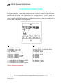
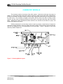
ATI A15/66 Residual Sulfite Monitor ANALOG OUTPUT A programmable isolated analog output signal is provided for interface with recorders, data loggers, or controllers. The analog output may be programmed for either 0-20 mA or 4-20 mA output. This output signal will be linearly proportional to the measured sulfite concentration, and may be scaled over ranges of 0-0.1 to 0-20.00 PPM. Also, the output may be spanned for non-zero based ranges as well. Both the zero and full scale output values are programmable so that an output of 1-10 PPM could be set if desired. If a zero based voltage output is required, this can easily be accommodated by selecting a 0-20 mA output and placing a shunt resistor across the output. For instance, a 50 ohm resistor will convert the output to 0-1 VDC while a 250 ohm resistor will provide 0-5 VDC. This will allow the output to accommodate systems with zero based voltage inputs. Programming the analog output is done in the CONFIGURATION menu as described in items 11, 12 and 13 on page 24. Connection of the output is made to the terminals shown in Figure 6. SIMULATE MODE OF OPERATION As previously noted, A15/66 monitors contain a mode of operation called “SIM” or simulate. This mode of operation allows the user to adjust the sulfite value manually in order to check devices wired to either the mA output or the alarm contacts. To enter simulate mode, press the MODE key until the main display is on the LCD. Press CAL once and then use the UP key to change the display to SIM. Press ENTER and the display will flash UPDATE and the display will then read “0.000 SIM A B”. Pressing the UP arrow will increase the sulfite value on the display. The 4-20 mA output will increase as the sulfite value increases. Any recorders or remote reading devices that are connected to the 4-20 mA output should respond to the increasing values. You can adjust the value to any number desired. If the value you set on the display is above an alarm setpoint, the relay for that setpoint should activate, as should any alarm or control devices wired to that relay. Using the simulate mode of operation can be very useful in verifying operation of control or recording systems that use this equipment. Be sure to return the monitor to AUTO mode of operation when all simulation work is complete. TEMPERATURE MEASUREMENT A temperature element is located in the overflow chamber of the reactor module to measure the temperature of the sample after stripping. No adjustments are required for this part of the system. However, it is important to note that the measured temperature is often quite different than the temperature of the water at the overflow chamber below the monitor. Some sample heating or cooling can occur in the sample handling system. The temperature measurement is used to compensate the measurement and must reflect the stripped sample temperature. Do not try to adjust the displayed temperature to the sample temperature at the overflow. It is not designed to provide this measurement. There are 2 white wires coming from the sensing element that are connected to the PCB on the terminals labeled “RTD wiring”. If disconnected make sure the jumper is in place after reassembly. 29 O&M Manual Rev-W (8/10)