1
How to Control the Implementation of VHDL
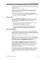
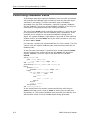
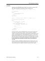
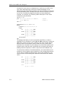
If you will be assigning properties to signals that are part of nonbinary data types (such as bit_vector, integer or std_logic_vector),
then you will need to be aware of how the VHDL synthesizer generates
signal names from these data types. When the VHDL synthesizer
expands an array data type into signals for each bit, it appends a
numeric suffix to the array name in the format _n_, where n is the
array index for each element of the data type. The following example
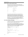
shows how to write a property for std_logic_vector data types.
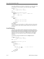
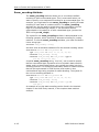
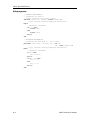
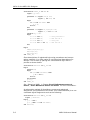
library ieee;
use ieee.std_logic_1164.all;
entity example is
port (Q: in std_logic_vector (7 downto 0);
D: out std_logic_vector (3 downto 0));
attribute property: string;
attribute property of example: entity is
"AMDMACH GROUP A Q_7_ Q_6_ Q_5_ Q_4_ Q_3_ Q_2_ Q_1_ Q_0_"
& CR &
"AMDMACH GROUP B D_3_ D_2_ D_1_ D_0_";
end example;
The actual property string that you must enter in the attribute
statements are defined in the appropriate device-specific
documentation provided with the device kit being used.
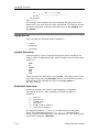
Macrocell Attribute
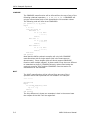
The macrocell attribute allows components in a design to be flagged
as external, device-specific macrocells in a hierarchical design.
Components that are specified with the macrocell attribute do not
have VHDL source files associated with them (unless VHDL source files
have been written or provided for simulation purposes), and are
resolved by the device fitting software during device mapping.
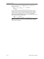
When the macrocell attribute is specified for a component, the
resulting output will include a hierarchical reference to the specified
external module, and the Project Navigator will not attempt to find a
source module in the design to resolve the hierarchy.
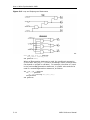
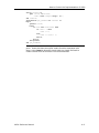
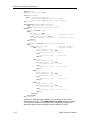
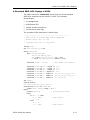
The following example demonstrates how the macrocell attribute can
be used:
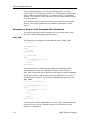
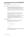
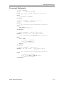
library ieee;
use ieee.std_logic_1164.all;
entity top is
port (a: in std_logic;
b: in std_logic;
out1: out std_logic;
out2: out std_logic );
end top;
architecture schematic of top is
component submod_def
port (in1: in std_logic;
in2: in std_logic;
and1: out std_logic;
4-16
VHDL Reference Manual