1
6-26
UG-01143
2015.05.11
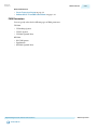
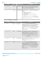
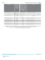
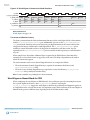
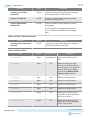
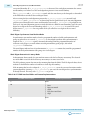
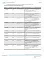
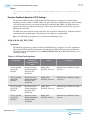
Ports and Parameters
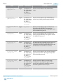
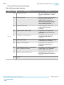
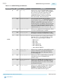
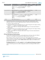
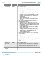
Port Name
Direction
Output
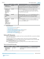
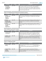
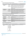
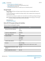
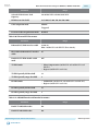
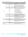
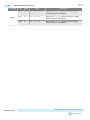
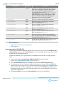
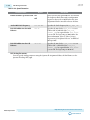
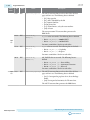
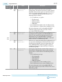
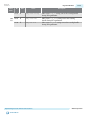
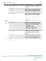
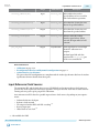
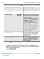
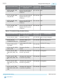
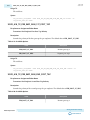
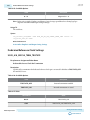
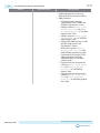
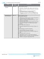
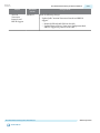
reconfig_waitrequest
Clock Domain
reconfig_clk
Description
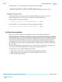
A one-bit signal that indicates the
Avalon interface is busy. Keep the
Avalon command asserted until this
signal goes low.
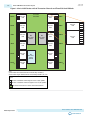
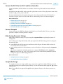
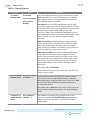
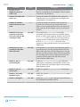
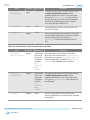
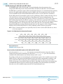
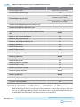
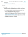
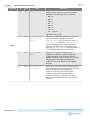
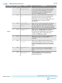
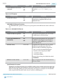
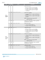
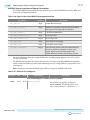
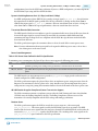
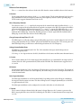
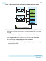
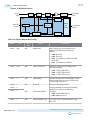
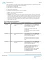
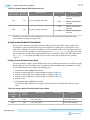
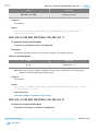
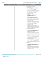
When Share reconfiguration interface is off, the Native PHY IP provides an independent reconfigura‐
tion interface for each channel. For example, when a reconfiguration interface is not shared for a fourchannel Native PHY IP instance, reconfig_address[9:0] corresponds to the reconfiguration address
bus of logical channel 0, reconfig_address[19:10] correspond to the reconfiguration address bus of
logical channel 1, reconfig_address[29:20] corresponds to the reconfiguration address bus of logical
channel 2, and reconfig_address[39:30] correspond to the reconfiguration address bus of logical
channel 3.
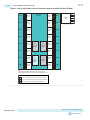
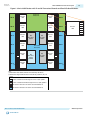
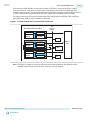
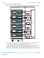
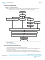
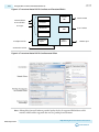
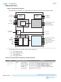
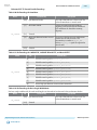
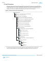
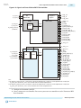
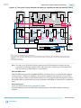
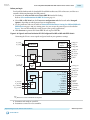
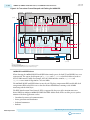
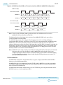
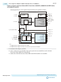
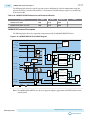
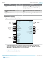
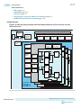
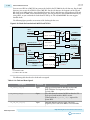
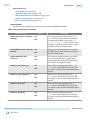
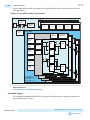
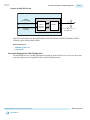
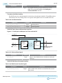
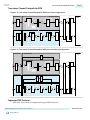
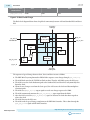
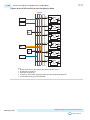
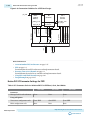
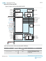
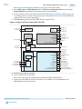
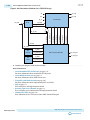
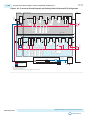
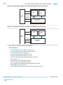
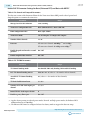
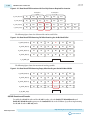
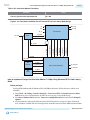
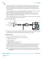
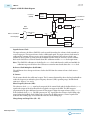
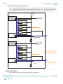
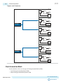
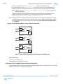
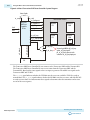
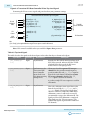
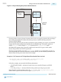
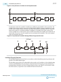
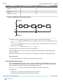
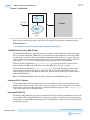
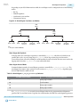
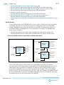
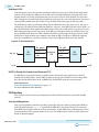
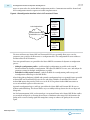
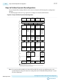
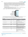
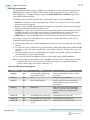
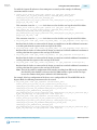
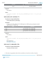
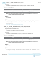
The following figure shows the signals available when the Native PHY is configured for four channels and
the Share reconfiguration interface option is not enabled.
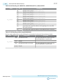
Figure 6-12: Signals Available with Independent Native PHY Reconfiguration Interfaces
Native PHY IP
reconfig_clk[3:0]
reconfig_reset[3:0]
reconfig_write[3:0]
reconfig_read[3:0]
reconfig_address[39:0]
reconfig_writedata[127:0]
reconfig_readdata[127:0]
reconfig_waitrequest[3:0]
clk
reset
write
read
address
writedata
readdata
waitrequest
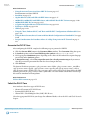
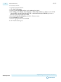
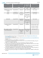
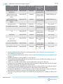
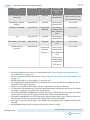
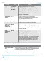
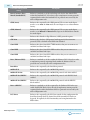
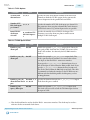
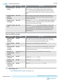
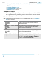
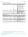
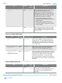
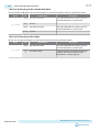
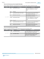
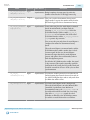
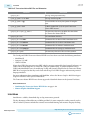
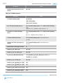
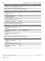
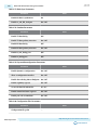
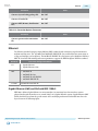
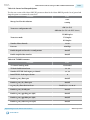
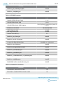
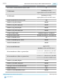
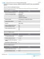
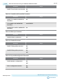
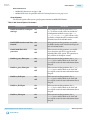
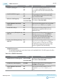
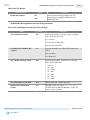
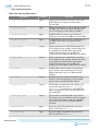
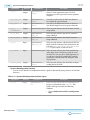
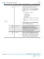
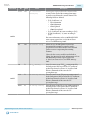
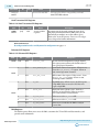
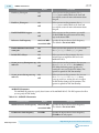
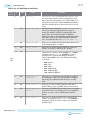
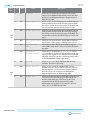
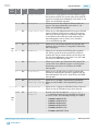
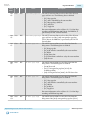
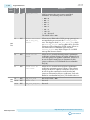
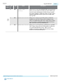
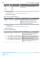
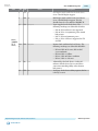
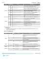
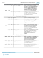
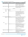
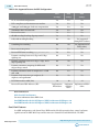
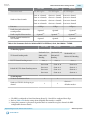
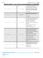
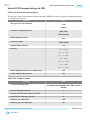
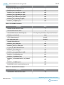
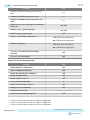
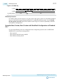
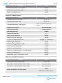
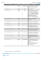
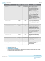
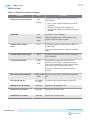
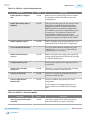
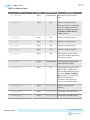
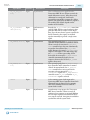
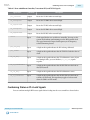
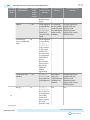
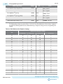
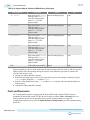
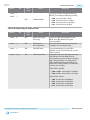
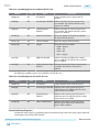
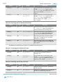
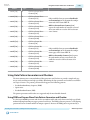
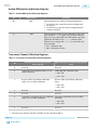
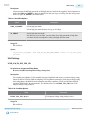
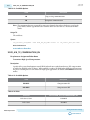
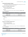
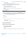
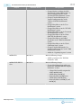
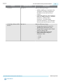
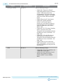
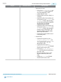
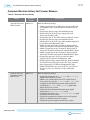
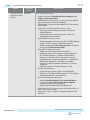
Table 6-17: Reconfiguration Interface Ports with Independent Native PHY Reconfiguration Interfaces
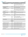
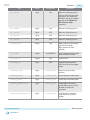
The reconfiguration interface ports when Share reconfiguration interface is disabled. <N> represents the number
of channels.
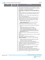
Port Name
Direction
Clock Domain
reconfig_clk[N-1:0]
Input
N/A
reconfig_reset[N-1:0]
Input
reconfig_clk
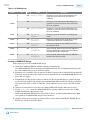
reconfig_write[N-1:0]
Input
reconfig_clk
reconfig_read[N-1:0]
Input
reconfig_clk
reconfig_address[N*10-1:0]
Input
reconfig_clk
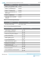
reconfig_writedata[N*32-1:0]
Input
reconfig_clk
Altera Corporation
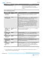
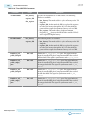
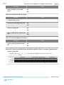
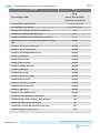
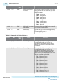
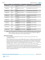
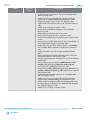
Description
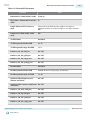
Avalon clock for each channel. The
clock frequency is 100-125 MHz.
Resets the Avalon interface for each
channel.
Write enable signal for each channel.
Signal is active high.
Read enable signal for each channel.
Signal is active high.
A 10-bit address bus for each channel.
A 32-bit data write bus for each
channel. Data to be written into the
address indicated by the corresponding
address field in reconfig_address.
Reconfiguration Interface and Dynamic Reconfiguration
Send Feedback