1
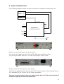
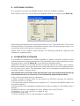
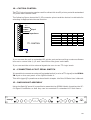
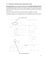
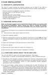
QCBOX
AMPLIFIER & SWITCH BOX
MODEL 4
USER'S MANUAL
AUDIOMATICA
© Copyright 1991-2004 by AUDIOMATICA SRL
All Rights Reserved
Edition 5.0, January 2004
IBM is a registered trademark of International Business Machines Corporation.
Windows is a registered trademark of Microsoft Corporation.
1
CONTENTS
1 - THE QCBOX MODEL 4 AMPLIFIER & SWITCH BOX.............................................. 3
2 - TECHNICAL SPECIFICATIONS ............................................................................... 3
3 - GENERAL CONDITIONS AND WARRANTY ............................................................ 4
4 - INTERNAL FUNCTIONAL DIAGRAM ....................................................................... 5
5 - BASIC CONNECTIONS ............................................................................................ 6
6 - DEFAULT INTERNAL SETTINGS ............................................................................ 7
7 - PARALLEL PORT CONFIGURATION ...................................................................... 8
8 - SOFTWARE CONTROL .......................................................................................... 10
9 - CALIBRATING SOFTWARE .................................................................................... 10
10 - CUSTOM CONTROL ............................................................................................. 11
11 - CONNECTING A FOOT PEDAL SWITCH ............................................................. 11
12 - RACK MOUNT ASSEMBLY .................................................................................. 11
13 - INTERNAL SETTINGS AND TROUBLESHOOTING ............................................ 12
2
1 - THE QCBOX MODEL 4 AMPLIFIER & SWITCH BOX
The QCBOX Model 4 amplifier and switch box is of invaluable help in everyday laboratory
use and when configuring an automatic or manual quality control setup.
The QCBOX Model 4 has an ultraslim design, increased power (50W@8Ohm) with
respect to its predecessors Model 1, 2 & 3 and wide range AC (90÷240V) power supply.
Its main feature is the possibility of internal switching, under software control, that
permits the measurement of the impedance and frequency response of the loudspeaker
(or D.U.T.) connected to its output sockets without changing the loudspeaker (or
D.U.T.) wiring; it is also possible to choose one among four inputs for the response
measurements; the internal switching is controlled via the parallel port of the PC.
A dedicated output, ISENSE, allows impedance measurements in constant voltage
mode as well voice coil current distortion analysis.
A dedicated input, PEDAL IN, permits an external foot pedal switch or TTL signal to be
connected and trigger QC operations.
2 - TECHNICAL SPECIFICATIONS
Inputs:
Functions:
Output power:
THD (@1 kHz):
Dimensions:
Weight:
AC:
Four line/microphone inputs with
selectable phantom power supply (8.2V)
One TTL input for external trigger
TTL controlled internal switches for impedance measurements
50W (8Ohm) with current sensing
0.004 %
23(w)x23(d)x4(h)cm
1.4kg
90÷240V
3
3 - GENERAL CONDITIONS AND WARRANTY
THANKS
Thankyou for purchasing your QCBox Model 4. We hope that your experiences using
QCBox Model 4 will be both productive and satisfying.
CUSTOMER SUPPORT
Audiomatica is committed to supporting the use of the QCBox Model 4, and to that end,
offers direct support to end users. Our users all around the world can contact us directly
regarding technical problems, bug reports, or suggestions for future software
enhancements. You can call, fax or write to us at:
AUDIOMATICA SRL
VIA MANFREDI 12
50136 FLORENCE, ITALY
PHONE: +39-055-6599036
FAX: +39-055-6503772
AUDIOMATICA ON-LINE
For any inquiry and to know the latest news about the QCBox Model 4 and other
Audiomatica’s products we are on the Internet to help you:
AUDIOMATICA website: www.audiomatica.com
CLIOwin website: www.cliowin.com
E-MAIL: [email protected]
AUDIOMATICA’S WARRANTY
Audiomatica warrants the QCBox Model 4 against physical defects for a period of one
year following the original retail purchase of this product. In the first instance, please
contact your local dealer in case of service needs. You can also contact us directly as
outlined above, or refer to other qualified personnel.
WARNINGS AND LIMITATIONS OF LIABILITY
Audiomatica will not assume liability for damage or injury due to user servicing or misuse
of our product. Audiomatica will not extend warranty coverage for damage of the
QCBox Model 4 caused by misuse or physical damage. Audiomatica will not assume
liability for the recovery of lost programs or data. The user must assume responsibility
for the quality, performance and the fitness of Audiomatica software and hardware for
use in professional production activities.
The CLIO SYSTEM, CLIOwin and AUDIOMATICA are registered trademarks of Audiomatica
SRL.
4
4 - INTERNAL FUNCTIONAL DIAGRAM
The first diagram shows us the unit set for impedance measurements (in Internal
Mode referring to CLIOwin software, see chapter 13 of the User's Manual); in this
situation the power amplifier and inputs are disconnected while the speaker load is
presented in parallel with CLIO's input and output; this method of impedance
measurement relies on the precise knowledge of the analyzer's output impedance and
stimulates the D.U.T with signals of small amplitude.
Pedal In
PC
TTL control
Input 1
Input 2
Input 3
Input 4
To CLIO
From CLIO
Speaker
20 dB
I Sense
Internal connections for impedance measurements (Internal Mode)
The second diagram shows us the unit set for frequency response measurements;
in this situation CLIO's output is fed to the power amplifier that drives the speaker under
test while one among four inputs is directed to CLIO's input.
Pedal In
PC
TTL control
Input 1
Input 2
Input 3
Input 4
To CLIO
From CLIO
Speaker
20 dB
I Sense
Internal connections for frequency response measurements
NOTE: when the unit is set for frequency response measurements it is possible to
measure the current flowing in the D.U.T. through the ISENSE output; this permits
impedance measurements stimulating the D.U.T. with signals of variable amplitude up
to the amplifier's maximum power or voltage. Refer to chapter 13 of the CLIOwin User's
Manual.
5
5 - BASIC CONNECTIONS
The following diagram shows the basic connections needed to operate the unit.
INPUT A
INPUT B
CLIO
OUTPUT A
OUTPUT B
LPT PORT
TTL CONTROL
I SENSE
BLACK
RED
FROM CLIO
QCBOX MODEL 4
AMPLIFIER&SWITCHBOX
INPUT 1
TO CLIO
INPUT 2
INPUT 3
INPUT 4
AC POWER
90 - 240 VAC
Please connect (referring to the front panel):
1) A pin-to-pin cable from the "From CLIO" RCA plug to CLIO's output.
2) A pin-to-pin cable from the "To CLIO" RCA plug to CLIO's input.
Please connect (referring to the rear panel):
3) A 25-poles male-female D cable from the "TTL Control" plug to a free PC parallel port.
4) A standard IEC AC cord in the AC Power receptacle.
There is no mains switch. Now you can plug the AC cord in the wall outlet and
verify the lighting of the front panel LED.
6
6 - DEFAULT INTERNAL SETTINGS
The QCBox Model 4 can be operated also if the TTL control cable is not connected
to the parallel port of the PC.
In this particular case, when software control doesn't take place, the unit operates in
the following mode:
Internal setting: frequency response.
Input: enabled input 4.
I SENSE: enabled.
7
7 - PARALLEL PORT CONFIGURATION
The parallel port you use to control the QCBOX Model 4 must be configured in
STANDARD (or NORMAL or AT) mode.
Be sure that the parallel port is NOT in ECP mode otherwise the software control
won't take place.
There is a simple way to check if the parallel port is properly configured. Click with the
right mouse button on the 'My Computer' icon on the Windows desktop. Then click
'Properties', select the 'Hardware' tab and press the 'Device Manager' button as in figure.
Then select 'Ports (COM&LPT)'. The situation above is correct, the parallel port is
configured in standard mode.
You may find the following situation:
In this case the parallel port must be reconfigured as outlined before. The only way to
8
do this is from within BIOS settings at the computer startup. This is usually accomplished
pressing a particular key or sequence of keys while your PC is booting; the correct key
to press normally shows up during the early booting of the computer: the most common
is the ‘Del’ key but you may need to press ‘F2’ or a different one.
When inside BIOS you should locate a menu like ‘INTEGRATED PERIPHERALS’ or
'PERIPHERALS SETUP' inside which there are listed the peripherals present and their
settings. Locate the parallel port settings and change them from ECP to Normal.
9
8 - SOFTWARE CONTROL
It is possible to control the QCBOX Model 4 from the CLIOwin software.
Run CLIOwin, then click on the External Hardware Button (or simply press Shift-F4).
Select the proper parallel port and choose Model 4 in the 'Type' drop down. The control
should be active; an acoustic confirmation should come from the internal relays, you
should hear them clicking when changing inputs.
Please refer to the CLIOwin User's Manual for executing frequency response and
impedance measurements.
9 - CALIBRATING SOFTWARE
It is possible to calibrate the CLIOwin software to obtain maximum precision when
executing current sensing measurement. The calibration relies on the input of the correct
sensing resistor value (I Sense R) in the External Hardware panel.
Inside the unit there is a sensing resistor of nominal value of 0.1 Ohm; as it is rather
difficult to maintain such a low value under strict production control the software allows
for the input of its value. The calibration relies on an impedance measurement of a
precision resistor of known value.
Please enter the value of 0.1 Ohm; this will give you reasonable precision during
measurements even in absence of the calibration described hereafter.
If you want to proceed with the calibration:
1) Take a resistor of known value (in the range 10 to 22 Ohm); assume, for example,
a known resistor of 10 Ohm
2) Connect the resisitor directly to the output (D.U.T.) socket of the QCBox (don't use
connecting cables)
3) Simply perform an impedance measurement (refer to chapter 13 of CLIOwin User's
Manual)
4) Read the value of its modulus at 1kHz; assume you read 9.5 Ohm
5) Multiply 0.1 by 1.05 (10/9.5) to obtain 0.105
6) Input this new value
7) Verify calibration with a new impedance measurement
10
10 - CUSTOM CONTROL
The TTL Control connector can be used for a direct link to a PC printer port with a standard
25 poles male-female cable.
The following figure shows the D-25 connector pinout and the device's truth table for
selecting its appropriate internal function.
1
14
2
15
3
16
4
17
5
18
6
19
7
20
8
21
9
22
10
23
11
24
12
25
13
BIT 0
BIT 1
Input
BIT 2
BIT 3
Impedance
FUNCTION
INPUT 1
INPUT 2
INPUT 3
INPUT 4
IMPEDANCE
I SENSE
TTL CONTROL
BIT 0
0
1
0
1
x
x
BIT 1
0
0
1
1
x
x
BIT 2
0
0
0
0
x
x
BIT 3
1
1
1
1
0
1
If you connect the unit to a standard PC printer port and are writing a custom software
be sure to control bits 0,1,2 and 3 and follow the given truth table.
If you connect the unit to external signals be sure to use TTL logic levels.
11 - CONNECTING A FOOT PEDAL SWITCH
It is possible to connect an external foot pedal switch (or wire a TTL signal) to the PEDAL
IN input on the rear panel of the QCBox Model 4.
This will trigger QC operations as described in chapter 14 of the CLIOwin User's Manual.
12 - RACK MOUNT ASSEMBLY
Using the Rack QC panel it is possible to assemble the QCBOX Model 4 together the SC01 Signal Conditioner so that they can be mounted in a standard 19” rack frame.
CLIOQC
OUT
IN
AUDIOMATICA
D.U.T.
1
2
3
4
ISENSE
TO CLIO
FROM CLIO
A
B
A
B
11
13 - INTERNAL SETTINGS AND TROUBLESHOOTING
If you want to make one of the possible internal settings disconnect the unit from
the mains power and then carefully open the unit; locate SW2 from the figure below
and make the appropriate selection. It is possible, using the dip switch SW2, to select
a phantom power supply of 8.2V on each input separately (to power an Audiomatica
MIC-01 or MIC-02 microphone). When a switch is ON the phantom power is present
at that input.
The unit is factory set with the phantom power enabled on all input.
The QCBox Model 4 is also equipped with one 2A 250VAC internal mains fuse.
FU1 - 2A 250VAC FUSE
SW2 - PHANTOM SUPPLY
12