1
10/29/2014
C005066
Client Version of the
Interface Configuration Document For:
CR900FD
CR1000
CR1400
CR2300
CR2600
CR3600
CR3600DPM
CR4405
CR6000
CR8000
Page 1 of 72
© 2014 The Code Corporation 12393 South Gateway Park Place Suite 600, Draper, UT 84020 (801) 495-2200 FAX (801) 495-0280
10/29/2014
Table of Contents
1
2
3
Scope .................................................................................................................... 3
Notations .............................................................................................................. 3
Host to Reader Command Overview ..................................................................... 4
3.1
Packetized Commands ...................................................................................... 4
3.2
Text Commands ................................................................................................ 4
3.3
Barcode Commands .......................................................................................... 4
3.4
Training ............................................................................................................. 4
4 Communication Medium ....................................................................................... 4
4.1
USB Enumeration PID (VID=11FA) ..................................................................... 5
5 Reader to Host Communication............................................................................. 5
5.1
Raw Data .......................................................................................................... 5
5.2
Packet Data ....................................................................................................... 5
6 Host to Reader Communication............................................................................. 9
6.1
Text Commands ................................................................................................ 9
6.2
Packetized Commands .................................................................................... 10
6.3
Command Types ............................................................................................. 11
7 File Installation.....................................................................................................16
7.1
Simple Protocol............................................................................................... 16
8 Reader Settings ....................................................................................................17
8.1
Binary Dip Switch ............................................................................................ 17
8.2
Field of Interest............................................................................................... 18
8.3
Reader Settings Table ..................................................................................... 18
9 Radio Commands .................................................................................................65
9.1
Bluetooth Commands ..................................................................................... 65
10
Code Reader Batch (CRB) System ......................................................................65
11
Symbology Detail Settings .................................................................................66
11.1 PharmaCode ................................................................................................... 66
12
Appendix: Example CRC16 C Code .....................................................................67
13
Appendix: Example CRC14 C Code .....................................................................70
14
Appendix: Custom Keyboard XML File Formatting ............................................71
Page 2 of 72
© 2014 The Code Corporation 12393 South Gateway Park Place Suite 600, Draper, UT 84020 (801) 495-2200 FAX (801) 495-0280
10/29/2014
1 Scope
This Interface Configuration Document (ICD) specifies the communication protocol between the Code
Reader™ 900FD (CR900FD), Code Reader™ 1000 (CR1000), Code Reader™ 1400 (CR1400), Code
Reader™ 2300 (CR2300), Code Reader™ 2600 (CR2600), Code Reader™ 3600 (CR3600), Code Reader™
3600 DPM (CR3600 DPM), Code Reader™ 4405 (CR4405), Code Reader™ 6000 (CR6000) or Code
Reader™ 8000 (CR8000) hardware and application software that runs on the Host computer, specific
Reader commands, examples of a variety of ways to communicate and send data to the Reader (i.e.,
RS232, USB) and command/communication types.
Make sure to use the latest released firmware for default values listed in Section 8.
2 Notations
The interface protocol is described as a set of grammars, indicated by different type styles and
symbols. These indications are listed in the table below.
Example
Indication
Grammar
Text-Command
Italic type
Syntactic categories (non-terminals)
space
Bold type
Terminal symbols
0xFF
0x prefix indicating hexadecimal
Literal byte values
‘X’
Single quotes
Literal ASCII characters
SOH
All caps
Non-printable ASCII characters
PageUp
Key name
key press-release sequence
shift
Key plus down arrow
Key-down only
shift
Key plus up arrow
Key-up only
esc | tab
Vertical bar
Alternatives (this or that)
dataopt
opt.
packet-typenz
nz
(nz subscript)
Applies to all packets except z type packets
crc16nr
nr
(nr subscript)
Applies to packets sent in “non-raw” mode, i.e.,
in “packet” mode
(opt subscript)
Optional terminals and non-terminals
Page 3 of 72
© 2014 The Code Corporation 12393 South Gateway Park Place Suite 600, Draper, UT 84020 (801) 495-2200 FAX (801) 495-0280
10/29/2014
3 Host to Reader Command Overview
This section is intended to introduce developers/users to the basic command types of the Reader.
There are two ways to send a command to the Reader: from a Host computer, or by scanning a
barcode containing a command sequence. In addition, there are two methods of sending a command
from a Host computer to the Reader: packetized and text commands.
3.1 Packetized Commands
Packetized commands are the most reliable way to communicate to the Reader. The packet consists of
a prefix and a suffix. The prefix contains the amount of data to be transmitted and the suffix contains
error detection. Unlike text commands, packetized commands are always enabled. (See Section 6.2)
3.2 Text Commands
Text commands are provided as an easy way to send a command to a Reader but they lack the
reliability of packetized commands. In addition, text commands must be enabled. Text commands can
easily be sent from a terminal program and use a %xx (similar to URL encoding) to translate an escape
sequence containing a 2-digit hex value corresponding to the single 8-bit ASCII character. This allows
non-printable ASCII characters to be entered via the terminal program. Text commands can be sent via
the RS232, USB Virtual COM (VCOM) or USB HID mode by using appropriate communication software.
In addition, the developer/user may send text commands by using CRB files. (See Section 9)
3.3 Barcode Commands
The Reader will recognize the following sequence within a barcode as a command to the Reader:
SOH ‘X’ GS STX Text-Command EOT (Packet does not contain spaces)
The Text-Command portion contains a text command as described above.
Because the Barcode Command is terminated with ASCII EOT, the Text-Command may not contain EOT.
If the Text-Command needs to contain EOT, encode it as %04.
3.4 Training
Code Corporation highly recommends attending technical training provided by Code via webinar and
on site. This training is designed to provide in-depth knowledge/usage of the ICD for developers and
users.
4 Communication Medium
The Reader communicates with the Host via USB (keyboard/HID/VCOM), RS232, Bluetooth, or WiFi.
The Host includes appropriate hooks and/or drivers to enable two-way communication with the
Reader.
Page 4 of 72
© 2014 The Code Corporation 12393 South Gateway Park Place Suite 600, Draper, UT 84020 (801) 495-2200 FAX (801) 495-0280
10/29/2014
Note: USB keyboard communications are one-way, from the Reader to Host only. A special sequence is
available to switch the Reader from keyboard to HID communication mode. See register 1B.
4.1 USB Enumeration PID (VID=11FA)
200 – KBD Mode
201 – IBM Handheld
202 – HID_Native
203 – Not used
204 – HID_VCOM
205 – CodeXML Modem HID Keyboard
206 – HID POS
207 – Bootloader
208 – CodeXML Modem HIDPOS
209 – CodeXML Modem HID Bulk
1009 - DFU
5 Reader to Host Communication
The Reader may be configured in raw mode, where no packet framing or check characters are sent,
and packet mode (See sections 3.1 and 3.2) The Reader may also be configured to expect an
acknowledgement from the Host after each packet and automatic retry when no acknowledgement is
received. Standard “one-way” mode of operation uses raw packets, no expected response from Host,
and no automatic retry. Standard “two-way” mode of operation uses packets with framing and checks
characters, expects a response from the Host, and automatically resends. If no Acknowledgement is
received (ACK), three (3) attempts to resend are made.
5.1 Raw Data
Reader to Host communication consists of decoded raw data having no framing or check characters.
Raw data is sent with no “end of packet” data (crc16), expects no response from Host and no data is
resent.
5.2 Packet Data
Data from the Reader to the Host consist of packets as specified below. Packetized data is sent using
ACK/NAK protocols with framing and check characters. Packets are delivered asynchronously as
barcodes are read and in response to Host to Reader commands. For keyboard communication (USB
keyboard), all ASCII-characters are transmitted as keyboard-sequences. For all other communication
ports, all ASCII-characters are transmitted as ASCII-bytes.
Note: Even though the data size field allows up to 65535 bytes of data in a packet, the actual size of a
packet either in raw or in packet mode including data and packet overhead is a maximum of 16384
bytes.
packet:
start:
packet-start:
protocol-version:
Reader-id:
packet-number:
start packet-typenz dataopt end
packet-startnr | codeXML-startnz
SOH ‘X’ ‘R’ protocol-version Reader-id packet-number timestamp data-size
‘1’
big-endian 32-bit number
data-packet-number | cmd-packet-number
Page 5 of 72
© 2014 The Code Corporation 12393 South Gateway Park Place Suite 600, Draper, UT 84020 (801) 495-2200 FAX (801) 495-0280
10/29/2014
data-packet-number: any byte value in the range [0,7f]; increments with each packet; does not
increment with resends; used with z and a packets only
cmd-packet-number: any byte value in the range [80-ff]; increments with each packet; does not
increment with resends; used with all packets other than z and a
timestamp:
big-endian 32-bit number, indicates timestamp in seconds (relative to Reader
power-up) (For all but z packets, the timestamp represents the time the packet
was sent to the Host; for z packets, the time the code was read.)
data-size:
big-endian 16-bit number indicating size of the data field (in bytes)
codeXML-start:
SOH ‘X’ RS tag_response ‘/’
tag_response:
‘ap’
packet-type:
Single ASCII-character in table below
data:
character
|
data character
character:
byte
|
keyboard-sequence
byte:
any byte value in range [0x00,0xFF]
keyboard-sequence: key
|
shift key shift
|
alt decimal-code alt
key:
~|1|2|3|4|5|6|7|8|9|0|-|=
|
q|w|e|r|t|y|u|i|o|p|[|]|\
|
a|s|d|f|g|h|j|k|l|;|’
|
z|x|c|v|b|n|m|,|.|/
|
space
|
esc | tab | shift | alt | ctrl | enter | backspace
|
f1 | f2 | f3 | f4 | f5 | f6 | f7 | f8 | f9 | f10 | f11 | f12
|
insert | delete | home | end | pageup | pagedown
|
left | right | up | down | keypadenter
|
digit
decimal-code:
digit | digit digit | digit digit digit (range [0,255])
digit:
keypad0 | keypad1 | keypad2 | keypad3 | keypad4
|
keypad5 | keypad6 | keypad7 | keypad8 | keypad9
end:
codeXML-endnz crc16nr
codeXML-end:
EOT
crc16:
big-endian 16-bit number representing crc16 of the packet, calculated over the
entire packet, excluding the crc16 itself. See source files crc16.[hc] in Appendix B
for details on the crc16 algorithm and polynomials to be used.
Page 6 of 72
© 2014 The Code Corporation 12393 South Gateway Park Place Suite 600, Draper, UT 84020 (801) 495-2200 FAX (801) 495-0280
10/29/2014
The following packet-types are defined:
a
Append decode data; indicates that data contains the first part of the decode data. A sequence
of ‘a’ packets always ends with a ‘z’ packet. The data of all ‘a’ packets in a group and the final ‘z’
packet should be concatenated by the Host.
d
Done response; command and its associated data were successfully received; data optionally
contains a null-terminated text message.
e
Error response; command was not successfully received; data optionally contains a nullterminated text message.
g
Start of a group of ‘z’ packets to follow, terminated by a ‘d’ or ‘e’ packet (‘d’ for complete group,
‘e’ for incomplete group)
i
indicates that data contains the zero-terminated Reader information string (of printable ASCII
characters and TAB) in the following format:
iVVVVWWWWXXXXSSSSSSSSSSAOODYYYYHHIIIIJJJJKKKKLLLL<TAB>Z…Z
m
r
z
where:
i indicates ‘I’ string output
VVVV is the application firmware version number;
WWWW is the core application firmware version number;
XXXX is reserved;
SSSSSSSSSS is the Reader’s serial number (ten digits);
A is the current execution state:
“A” means core is running
OO is the OEM identifier;
D is the display type:
“0” is no display device.
YYYY is reserved;
HH is the hardware revision;
IIII is the hardware type identifier (value in register 21B);
JJJJ is the boot application version;
KKKK is the operating system kernel version;
LLLL is the root file-system version;
<TAB> is the ASCII TAB character;
Z…Z is the OEM decoder version: a null terminated string of printable ASCII characters.
Message response; data contains a message (comment). ‘m’ packets are not sent when the
Reader is in “raw” mode.
Read code failure; decoder attempted but failed to read a code.
Decoded data from a code; data contains the data decoded from the code.
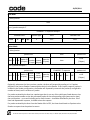
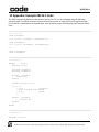
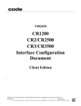
In “raw” mode (as opposed to “packet” mode), type m packets are not sent, only the decoded data is
sent for type z packets, and all other packets are sent without the packet-start and crc16 fields. In
“packet-mode,” the packet-start and crc16 fields are always sent. (See Figure 1)
Page 7 of 72
© 2014 The Code Corporation 12393 South Gateway Park Place Suite 600, Draper, UT 84020 (801) 495-2200 FAX (801) 495-0280
10/29/2014
Raw Mode
‘z’ (data) packet:
Data
(non-z) packet:example ‘i'
CodeXML® ‘i’ response example
CodeXML-start
SOH
‘X’
RS
packet-type
data
CodeXML-end
‘i’
VVV…
EOT
‘ap/’
Packet Mode
‘z’ (data) packet:
packet-start
SOH ‘X’ ‘R’ ‘1’
packet
time
Reader ID
data size
number stamp
(4 bytes)
(2 bytes)
(1 byte) (4 bytes)
Data
packet-end
crc16
data
(2 bytes)
(non-z) packet:example ‘i’
packet-start
CodeXML® ‘i’ response
packet-end
packet
time
Reader ID
data size
SOH ‘X’ ‘R’ ‘1’
number stamp
SOH ‘X’ RS ‘ap/’ ‘i’ VVV… EOT
(4 bytes)
(2 bytes)
(1 byte) (4 bytes)
crc16
(2 bytes)
Figure 1: Example 'z' and 'i' Packets in Raw and Packet Modes
Optionally, whenever the Host receives a packet, the Host will respond by sending a Y or R packet
(defined in the Host to Reader Communication section) to the Reader. If the ‘expect response’ option is
enabled in the Reader configuration, the Reader will repeatedly retransmit the packet (a configurable
number of times) until it receives a Y packet.
If a packet received by the Host has a packet-type that is not any of the valid types listed above or has
the same packet-number as the last processed packet of the corresponding type (command or data),
the entire packet – up to and including end or until timeout – should be discarded by the Host. If the
Host had requested a response, it should reissue the request.
If a packet received by the Host from the Reader fails its CRC, the Host should send an R packet to the
Reader to request that the packet be resent.
Page 8 of 72
© 2014 The Code Corporation 12393 South Gateway Park Place Suite 600, Draper, UT 84020 (801) 495-2200 FAX (801) 495-0280
10/29/2014
6 Host to Reader Communication
Commands and data from the Host to the Reader are sent in the form of commands as specified in this
section.
Commands are normally sent in USB Native, VCOM, or RS232 modes. Commands may not be sent via
keyboard modes.
Two command formats are supported: text-command and packetized-command. Text-command
format is applicable to RS232 and VCOM modes but only if the Reader is configured to accept this
format. Packetized-command format is applicable to all interfaces.
text-command:
See Section 6.1.
packetized-command:
See Section 6.2.
The command types are explained in Section 6.3.
After the Host sends each complete command, it should wait for a response packet from the Reader.
Expected responses are specified along with the command types in section 6.3. If the Reader responds
with an ‘e’ packet or doesn’t respond within a reasonable timeout period, the Host should resend the
command a reasonable number of times.
6.1 Text Commands
Text commands may be sent to the Reader in RS232 or VCOM mode using any serial communications
software (e.g., HyperTerminal).
Encoded-data is decoded by the Reader by replacing %xx by a single byte with the value specified by
the two hex-digits xx- (e.g., %25 would be replaced by character number 0x25, which is ASCII ‘%’).
text-command:
command-type:
encoded-data:
|
encoded-datum:
printable-character:
hex-digit:
|
|
carriage-return:
command-type encoded-dataopt carriage-return
Single ASCII character in the set defined in Section 6.3
encoded-datum
encoded-data encoded-datum
printable-character | % hex-digit hex-digit
any byte value in the range [0x20,0x7e]
‘0’ | ‘1’ | ‘2’ | ‘3’ | ‘4’ | ‘5’ | ‘6’ | ‘7’ | ‘8’ | ‘9’
‘A’ | ‘B’ | ‘C’ | ‘D’ | ‘E’ | ‘F’
‘a’ | ‘b’ | ‘c’ | ‘d’ | ‘e’ | ‘f’
0x0d
In order to eliminate inadvertent commanding of the Reader, Text Commands are disabled by
default.
To enable Text Commands requires an initial sequence: ;>PAx where x is as defined in section 8,
register 41. (Note: ‘A’ is the ASCII character that corresponds to 41 HEX.)
Page 9 of 72
© 2014 The Code Corporation 12393 South Gateway Park Place Suite 600, Draper, UT 84020 (801) 495-2200 FAX (801) 495-0280
10/29/2014
For example, to send the Reader commands by typing commands in HyperTerminal:
;>PA1
P(xx)yy
P(xx)yy
W
PA8
Where ;>PA1 enables text commands with echo and command responses, P%xxyy can be any desired
commands, W saves the settings just sent by the P command, and PA8 turns text commands back off
(except for the initial sequence). (Note: ‘A’ is the ASCII character that corresponds to 41 hex, thus
P%418 would be equivalent.)
Note: ;>PA1 is used for interactive text commands. If the commands are to be saved in a file and sent
non-interactively, use ;>PA7 instead; this enables text commands but disables echo and command
responses. (See Section 6.3, Section 8, and Section 9 for additional information.)
With text commands enabled, the following two examples can be sent to a Reader in RS232 mode
from HyperTerminal by just typing the example text.
Example 1 - Make the Reader beep/vibrate 3 times (Note: Readers with a vibration motor are the
CR1400, CR2600, CR3600 and CR6000.):
#%03 Expected output: should make Reader beep/vibrate 3 times
Example 2 - Set Reader to continuous-read, High Density field (FOI 0) only:
P(C4)5 Expected output: should set Reader to continuous-read, High Density field (FOI 0) only
6.2 Packetized Commands
Packetized commands consist of packetized data sent from Host to Reader to configure and cause the
Reader to perform certain functionalities (e.g. CodeXML® rules, and settings). Packetized commands
are always enabled, unlike text commands. In addition, they include error detection data, making them
more robust than text commands.
normal-command: prefix command-type data-size dataopt reserved crc14
prefix:
0xEE 0xEE 0xEE 0xEE
command-type:
Single ASCII character in the set defined in section 6.3
data-size:
byte value in range [0,240], which indicates size of data (in bytes)
data:
datum
|
data datum
datum:
any byte value in the range [0,255]
reserved:
0x00
crc14:
two consecutive bytes, each in range [0,127], representing the crc16 value &
with the value 0x7F7F, most significant byte first. The packet crc16 is calculated over the entire packet,
excluding the prefix and the crc14 itself. (See source files Appendices B and C for details on the crc16
algorithm and polynomials to be used, as well as how to implement appropriately for crc14
transmission.)
Page 10 of 72
© 2014 The Code Corporation 12393 South Gateway Park Place Suite 600, Draper, UT 84020 (801) 495-2200 FAX (801) 495-0280
10/29/2014
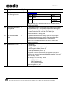
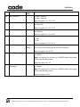
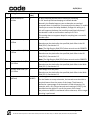
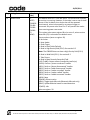
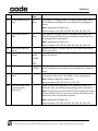
6.3 Command Types
#
Causes the Reader to beep and vibrate the specified number of times; data contains the number
as a single character in the range [0,127].
(The Reader will respond with d or e.)
Example – beep three times: #%03
Note: Behavior is defined per platform.
CR900FD/CR1000/CR2300/CR8000 – Beep three times.
CR1400/CR2600/CR3600/CR6000 – Beep and vibrate three times.
$
(
Note: Readers with a vibration motor are the CR1400, CR2600, CR3600 and CR6000.
Posts an event to the Reader; data contains the event number as a single character. See register
39 in Section 8 for a list of the event numbers.
(The Reader will respond with d or e.)
Causes the Reader to upload any logged error messages (no data)
(The Reader will respond with a g packet, zero or more z packets, and a final d or e. Each z
packet contains a portion of the requested data in its data field.
)
Note: This is very similar to the response to the X command; however, p packets are not
applicable and the g and d/e packets are not suppressed even in raw mode.)
Causes the Reader to erase its log of error messages (no data)
,
(The Reader will respond with d or e.)
Causes the Reader to send a list of current Reader settings (no data)
(The Reader will respond with d containing a space-separated list of all setting values (in order,
expressed as hexadecimal ASCII characters) or with e.)
/
(see ‘<’ command for saved Reader settings)
Toggle a bit (or bits) in a Reader setting; data contains a printable ASCII string in the following
format: hexadecimal register number in parentheses followed by a 32-bit signed integer value,
expressed in ASCII hexadecimal characters (with optional minus sign) or ASCII decimal characters
preceded by the ‘#’ character, e.g., /(2e)1000 or /(2e)#4096; the specified integer is XOR’ed with
the existing setting value.
The way a / command is handled is equivalent to a P command – the effects are immediate but
won’t survive a reboot. If you want the setting to be set after a reboot, issue a / then W or use
the newer C/ combination.
(The Reader will respond with d or e.)
1
Note: see Section 8 for possible Reader settings.
Indicates the start of a file download; data is empty. This command is followed by a sequence of
2 commands containing the file data and a download-end command (e.g., 5).
(The Reader will respond with d or e.)
Page 11 of 72
© 2014 The Code Corporation 12393 South Gateway Park Place Suite 600, Draper, UT 84020 (801) 495-2200 FAX (801) 495-0280
10/29/2014
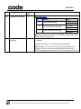
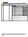
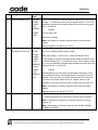
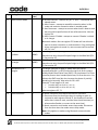
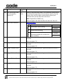
2
Indicates a continuation of a file download; data contains the next portion of the file data.
5
(The Reader will not send any response.)
Indicates the end of a regular file download; data contains the name of the file, which is from 1
to 200 letters, digits, periods, hyphens, and underscores, terminated with ASCII NUL.
9
(The Reader will respond with d, e, or f.)
Requests the Reader to delete a file from its storage; data contains the file name, terminated
with ASCII NUL.
;
<
Reserved (no operation – treated as a comment)
Causes the Reader to send a list of saved Reader settings (no data)
=
(The Reader will respond with d containing a space-separated list of all setting values (in order,
expressed as hexadecimal ASCII characters) or with e.)(see ‘,’ command for current Reader
settings)
Puts setting directly to Reader’s non-volatile memory so that it will take effect upon next reboot;
data is as defined in the / command; the specified integer replaces the existing setting value.
Note: this command can be used to set communication modes without losing communication
during the process.
(The Reader will respond with d or e.)
Note: The = command does not save changes immediately but those settings will be applied
after a reboot. If you issue an =(2B)0 command to change the value of register 2B from 1, then
until you reboot the value of 2B will still be 1. After you reboot the reader, the value of the 2B
register will be 0 when the reader is ready again. In order to have that setting be immediate and
survive a reboot you must either issue a P then a W command or use the newer C command.
C(2B)0 is the same as these two commands combined: P(2B)0, W
The = command is most useful to ‘pre-set’ a new communication mode that will become active
after a reboot.
(The Reader will respond with d or e.)
>
Note: Also see commands O, P, Q, /, =, W. See Section 8 for possible Reader settings.
Causes the Reader to send a string of text to the Host as a z packet;
data contains the text to send.
(The Reader will respond with a z packet containing the text.)
Page 12 of 72
© 2014 The Code Corporation 12393 South Gateway Park Place Suite 600, Draper, UT 84020 (801) 495-2200 FAX (801) 495-0280
10/29/2014
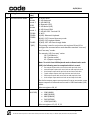
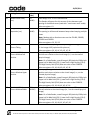
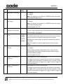
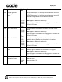
@
Causes the Reader to reset its internal date/timestamp to the specified time; data contains the
date and/or time in one of the following formats.
yyyy-mm-dd hh:mm:ss
yyyy-mm-dd hh:mm
hh:mm:ss
hh:mm
Note: the separators are optional; only digits are significant.
(The Reader will respond with d or e.)
A
Examples:
Set to midnight:
@00:00
Set to Sept 1, 2005 11:52:02 PM:
@2005-09-01 23:52:02
Notifies the Reader that the previously sent data were rejected for one of the following reasons:
The packet was encrypted and the decryption failed.
The Host (CodeXML® Modem) is locked to a different Reader.
The Reader should indicate to the user that the packet has been rejected; e.g., it may sound
error beeps. See related register 12F: notify-of-packet-rejection.
C
(The Reader will not respond to the Host.)
Apply a value to a register on the reader and save the value; data is in one of the following
formats:
(XXX)YYY where XXX is the register number and YYY is the setting value, both in ASCII hex. This
will change the value in the register and save it. For example C(26)64 will change the value of
register 26 to 0x64 and save this setting.
/(XXX)YYY where XXX is the register number and YYY is the setting value, both in ASCII hex. This
will toggle the bits in YYY and then save the resulting value (see / command). For example
C/(1F7)40 will toggle bit 6 of register 1F7 and save this setting.
O(XXX)YYY where XXX is the register number and YYY is the setting value, both in ASCII hex. This
will set the bits in YYY (change those bits to 1s) for register XXX (see O command). For example
CO(1F7)40 will set bit 6 of register 1F7 high and save this setting.
Q(XXX)YYY where XXX is the register number and YYY is the setting value, both in ASCII hex. This
will clear the bits in YYY (change those bits to 0s) for register XXX (see Q command). For example
CQ(1F7)40 will clear bit 6 of register 1F7 and save this setting.
Note: The C command saves changes immediately and those settings will survive a reboot. It is
equivalent to issuing a P and =, then a W command. C(2B)0 is the same as these three
commands combined: P(2B)0, =(2B)0, W
(The Reader will respond with d or e.)
Note: Also see commands O, P, Q, /, =, W. See Section 8 for possible Reader settings.
Page 13 of 72
© 2014 The Code Corporation 12393 South Gateway Park Place Suite 600, Draper, UT 84020 (801) 495-2200 FAX (801) 495-0280
10/29/2014
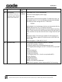
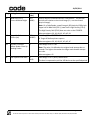
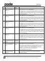
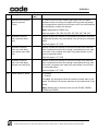
G
Get setting from Reader if followed by a register number in parenthesis.
G([prefix|suffix]) will return the prefix or suffix text.
(The Reader will respond with d and the setting valueor with e. The setting value, if numeric, will
be in hexadecimal, padded to 8 digits.)
I
Note: see Section 8 for possible Reader settings.
Requests the Reader to send its information string (no data).
(The Reader will respond with i or e.)
Optional Subcommands:
Is
J
J1
L
N
O
Retrieves Settings data – Available in 911+ firmware
Is[scd]
s – saved settings (same as ‘<’ command)
c – current settings (same as ‘,’ command
d – default settings
Ib
Sends XML formatted battery information to Host.
Requests the Reader to restore settings to defaults (no data).
(The Reader will respond with d or e.)
Complete restore of factory setup. Will overwrite the apps and settings.
Requests the Reader to send a list of its stored files
data is:
(no data) or “0”; all non-hidden files.
“1”; hidden files
(The Reader will respond in the same manner as with the ‘(’ command, each z packet containing
a file name as a NUL-terminated string of printable ASCII characters.)
Deletes all stored images (.jpg and .pgm) and buffered scan data (.log and .buf files)
Set a bit (or bits) in a Reader setting; data contains a printable ASCII string in the following
format: hexadecimal register number in parentheses followed by a 32-bit signed integer value,
expressed in ASCII hexadecimal characters (with optional minus sign) or ASCII decimal characters
preceded by the ‘#’ character, e.g., /(2e)1000 or /(2e)#4096;; the specified integer is ORed with
the existing setting value.
The way an O command is handled is equivalent to a P command – the effects are immediate
but won’t survive a reboot. If you want the setting to be set after a reboot, issue an O then W or
use the newer CO combination.
(The Reader will respond with d or e.)
Note: see Section 8 for possible Reader settings.
Page 14 of 72
© 2014 The Code Corporation 12393 South Gateway Park Place Suite 600, Draper, UT 84020 (801) 495-2200 FAX (801) 495-0280
10/29/2014
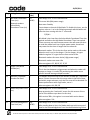
P
Put a value in a Reader register; data contains a printable ASCII string in the following format:
hexadecimal register number in parentheses followed by a 32-bit signed integer value,
expressed in ASCII hexadecimal characters (with optional minus sign) or ASCII decimal characters
preceded by the ‘#’ character, e.g., /(2e)1000 or /(2e)#4096; the specified integer replaces the
existing register value.
(The Reader will respond with d or e.)
Note: P([‘prefix’|’suffix’])<URL encoded text> will set the prefix or suffix to text.
Example: P(suffix)%01X%1ean//n%04 will create a CodeXML® sequence to send the scan code
for the enter key.
Note: The P command saves changes immediately but those settings will not survive a reboot. If
you issue a P(2B)0 command to change the value of register 2B from 1, then reboot the reader,
the value of the 2B register will be 1 when the reader is ready again. In order to have that
setting survive a reboot you must either issue a P then a W command or use the newer C
command. C(2B)0 is the same as these three commands combined: P(2B)0, W
(The Reader will respond with d or e.)
Note: Also see commands O, P, Q, /, =, W. See Section 8 for possible Reader settings.
Q
Clear a bit (or bits) in a Reader register; data contains a printable ASCII string in the following
format: hexadecimal register number in parentheses followed by a 32-bit signed integer value,
expressed in ASCII hexadecimal characters (with optional minus sign) or ASCII decimal characters
preceded by the ‘#’ character, e.g., /(2e)1000 or /(2e)#4096;; the ones-complement of the
specified integer is AND’ed with the existing register value.
The way a Q command is handled is equivalent to a P command – the effects are immediate but
won’t survive a reboot. If you want the setting to be set after a reboot, issue a Q then W or use
the newer CQ combination.
(The Reader will respond with d or e.)
R
T
Note: Also see commands O, P, Q, /, =, W. See Section 8 for possible Reader settings.
Requests that the previously sent packet be re-sent by the Reader; data may specify a maximum
packet size the receiver will accept: data is either empty or specifies a 16-bit big-endian
unsigned integer (2 bytes). If data is empty or specifies a size less than 32 (the minimum packet
size), the Reader will use its preferred maximum packet size. Otherwise, it will use the specified
max packet size (or less) and will fragment data across multiple smaller packets when necessary.
(The Reader will respond by resending its previous packet or with e if there was no previous
packet. If the max data size has changed, it may resend the previous data in a sequence of more
than one packet.)
Requests the current date and time (no data)
(The Reader will respond with d with data containing the date and time formatted as yyyy-mmdd hh:mm:ss.)
Page 15 of 72
© 2014 The Code Corporation 12393 South Gateway Park Place Suite 600, Draper, UT 84020 (801) 495-2200 FAX (801) 495-0280
10/29/2014
W
Requests the Reader to write its current settings from RAM to its non-volatile memory.
(The Reader will respond with d or e.)
Note: The W command saves changes that have been make with a /, O, P or Q so those settings
will survive a reboot. If you issue a P(2B)0 command to change the value of register 2B from 1,
then reboot the reader, the value of the 2B register will be 1 when the reader is ready again. In
order to have that setting survive a reboot you must either issue a P then a W command or use
the newer C command. C(2B)0 is the same as these two commands combined: P(2B)0, W
(The Reader will respond with d or e.)
Y
Note: Also see commands O, P, Q, /, =, W. See Section 8 for possible Reader settings.
Acknowledge the receipt of a packet; data specifies the received packet number (one byte).
(The Reader will not respond.)
Request the Reader to reboot
data is:
empty or ‘0’; reboot the Reader.
‘1’; restart application.
Z
^
(The Reader will respond with d or e before it reboots.)
Requests the Reader to upload the specified stored file; data contains the file name, terminated
with ASCII NUL.
The Reader will respond with:
1. ‘g’ packet containing “filename<tab>(size)”
2. ‘z’ packet(s)
3. ‘d’ packet containing “EOF<tab>(CRC16)”
_
Note: filename “help” is reserved to send command information.
Causes the Reader to wait for all buttons to be released and clear its event queue
|
(The Reader will respond with d or e.)
Process data as a decoded string.
(The Reader will respond with d or e.)
7 File Installation
7.1 Simple Protocol
The file is split into blocks of 236 or less bytes each and downloaded to the Reader via 1, 2, & 5
commands using the following sequence:
1)
Send a 1 command to initialize the download.
2)
Wait for a d or e response from the Reader or a timeout.
a)
If timeout or e response, restart the sequence at step 1.
b)
If d response, continue to step 3.
Page 16 of 72
© 2014 The Code Corporation 12393 South Gateway Park Place Suite 600, Draper, UT 84020 (801) 495-2200 FAX (801) 495-0280
10/29/2014
3)
Send a series of 2 commands, each with a portion of the file. (The Reader will not send
any response.)
4)
Send a 5 command to end the download and install the file.
5)
Wait for a d, e, or f response from the Reader or a timeout.
a)
If f response or timeout, restart the sequence at step 1.
b)
If e response, repeat step 5.
c)
If d response, file download has completed successfully.
Note: the timeout will need to be increased from the normal response timeout to allow the firmware
time to write the file to the flash memory.
8 Reader Settings
The Host sets the Reader settings using the /, C, O, P, Q, and = commands and reads them using the G,
‘,’, and < commands.
For example, the following C command sets register 2E to the value 0x7F.
C(2E)7F
Note: for two-digit register numbers (i.e., settings 00 through FD), an alternative format may be used:
in place of the parentheses and hexadecimal setting number, substitute a single character, which
represents the setting number. The equivalent to the example above is
C.7F
The ASCII ‘.’ character has the hexadecimal value 0x2E. In certain circumstances, such as with textcommands, “percent-encoding” may be used for encoding a character as a sequence consisting of the
percent character followed by two hexadecimal digits. With percent-encoding, the example may be
expressed as
C%2E7F
In Section 8.3 below, the Reg column is the register number, in hexadecimal, to be used with the
commands identified above. In the Default column, all values are in hexadecimal unless otherwise
specified. To use decimal values in commands you must precede the data with a pound sign ‘#’. The
following C command sets register 2E to the same value as the example above:
C(2E)#127
Since the single digit values of 0 through 9 are identical in decimal and hexadecimal, no indicator is
needed.
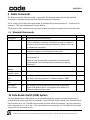
8.1 Binary Dip Switch
Some registers are what Code terms a ‘Binary Dip Switch’ where the value of each bit of the data string
switches on or off some part of the behavior of that register. The bits are numbered from least
significant to most (a.k.a. right to left). Each bit can be on or off (1 or 0).
An example of this is register 0A, ‘NEC 2 of 5 Options’. The following settings are possible:
Page 17 of 72
© 2014 The Code Corporation 12393 South Gateway Park Place Suite 600, Draper, UT 84020 (801) 495-2200 FAX (801) 495-0280
10/29/2014
Bit (R to L)
Controls
0
NEC 2 of 5 Decoding
1
Checksum checking
2
Strip checksum from the result
3
1 Digit Symbol Allowed
4
2 Digit Symbol Allowed
Value
0: Disabled
1: Enabled
0: Disabled
1: Enabled
0: Disabled
1: Enabled
0: Disabled
1: Enabled
0: Disabled
1: Enabled
Given the settings above, the binary string to turn on NEC 2 of 5 decoding with checksum checking and
the checksum stripped from the result string, allowing 2 digit symbols is 10111 (bits left to right). The
same string would be 0x17 or decimal 23.
Thus, the command to implement the settings above would be:
C(0A)17
Or
C(0A)#23
8.2 Field of Interest
The reader optics are typically split into two separate fields - Field Of Interest 0 (FOI 0) and Field Of
Interest 1 (FOI 1). In certain circumstances, these fields can be customized to the requirements of the
user. In the default configuration of these fields FOI 0 is the High Density (HD) field and FOI 1 is the
Wide (W) field.
At a given focus distance, the FOI 0 field is designed to read small, low-mil barcodes while the FOI 1
field is designed to pick up large, wide barcodes.
This document will refer to FOI 0 as HD and FOI 1 as Wide.
Note: The CR900FD is a single Field of Interest reader. There is no FOI 0 in the CR900FD.
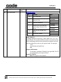
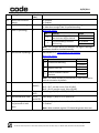
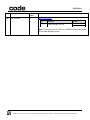
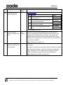
8.3 Reader Settings Table
Reg
Setting Name
Default
(Hex)
Comment
Page 18 of 72
© 2014 The Code Corporation 12393 South Gateway Park Place Suite 600, Draper, UT 84020 (801) 495-2200 FAX (801) 495-0280
10/29/2014
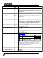
Reg
Setting Name
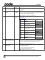
00
Bluetooth® Radio
Out-of-range indicator
04
05
08
Continuous Illumination
During Read
USB Declaration Wait
State
Reader Packet Format
Default
(Hex)
0
Comment
Binary Dip Switch
Bit
0
0
1
Controls
0
Vibrate
1
Beep
Value
0: Disabled
1: Enabled
0: Disabled
1: Enabled
Note: Readers with a vibration motor are the CR1400, CR2600,
CR3600 and CR6000.
0: Minimal Illumination (Illumination stops whenever not needed
during the Read Cycle – this produces a little more flashing but
reduces power consumption to a degree)
1: Leave Illumination On Until End of the Read Cycle
Leave illumination on during read
0: Declare enumeration after receipt of set LED status report
1: Declare enumeration after receipt of get report descriptor
command (used for some Windows CE-based devices)
Special case for USB enumeration that doesn’t require Host
keyboard response
1: Raw Mode
2: Packet Mode
4: Encrypted Packet Mode (Version 2)
5: AES Encryption Mode (Version 4)
6: Safe Upgrade Mode (Version 1)
This setting is used in conjunction with registers 1B and 42 to
configure the communication mode between standard “one-way”
and “two-way” modes.
For example, USB “two-way” native:
1B: 5 (USB Native)
08: 2 (packet mode)
42: 1 (expect response)
Also see registers: 1B, 42
Page 19 of 72
© 2014 The Code Corporation 12393 South Gateway Park Place Suite 600, Draper, UT 84020 (801) 495-2200 FAX (801) 495-0280
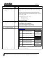
10/29/2014
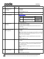
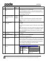
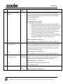
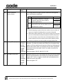
Reg
Setting Name
0A
NEC 2 of 5 Symbology
Default
(Hex)
0
Comment
Binary Dip Switch
Bit
0B
Matrix 2 of 5 Symbology 0
Controls
0
NEC 2 of 5 Decoding
1
Checksum checking
2
Strip checksum from the result
Binary Dip Switch
Bit
0C
Telepen Symbology
0
0F
Targeting Contro
1
13
1D Barcode
Aggressiveness
0
Value
0: Disabled
1: Enabled
0: Disabled
1: Enabled
0: Disabled
1: Enabled
Controls
0
Matrix 2 of 5 Decoding
1
Checksum checking
2
Strip checksum from the result
Value
0: Disabled
1: Enabled
0: Disabled
1: Enabled
0: Disabled
1: Enabled
0: Disabled
1: Enabled
0: Targeting Disabled
1: Targeting Enabled
0: Most Aggressive
1: Less Aggressive
2: Least Aggressive
Use this feature to minimize misreads on poorly printed 1D
barcodes
14
Image Transform
0
16
Data Matrix Rectangular 1
Symbology
Note: This feature requires firmware 956+ and CD 13.2.x+.
0: No Transform
1: Mirror – Enables decoding of mirrored Data Matrix, QR, Han Xin,
and Aztec symbologies. Those symbologies must be enabled.
0: Disabled
1: Enabled
Note: This register has no effect on a CR900FD without the proper
2D barcode decoding license.
Page 20 of 72
© 2014 The Code Corporation 12393 South Gateway Park Place Suite 600, Draper, UT 84020 (801) 495-2200 FAX (801) 495-0280
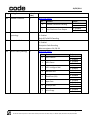
10/29/2014
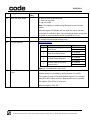
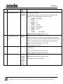
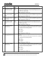
Reg
Setting Name
19
Data Matrix Symbology
Default
(Hex)
3
Comment
Binary Dip Switch
Bit
1A
Straight 2 of 5
Symbology
0
Controls
0
Data Matrix Decoding
1
Inverse Data Matrix Decoding
2
Mirror Data Matrix Decoding
Value
0: Disabled
1: Enabled
0: Disabled
1: Enabled
0: Disabled
1: Enabled
Note: This register has no effect on a CR900FD without the proper
2D barcode decoding license.
0: Disabled
1: Enabled
Straight 2 of 5 (with 2 or 3 start/stop codes) Decoding.
Note: Straight 2 of 5 with 2 start/stop is also called IATA 2 of 5.
Straight 2 of 5 with 3 start/stop is also called Industrial 2 of 5.
CD12.3.0 supports Industrial 2 of 5. CD 13.1.4 supports IATA 2 of 5.
Page 21 of 72
© 2014 The Code Corporation 12393 South Gateway Park Place Suite 600, Draper, UT 84020 (801) 495-2200 FAX (801) 495-0280
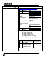
10/29/2014
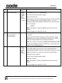
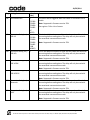
Reg
Setting Name
1B
Communications Mode
Default
(Hex)
USB
decode
board: 2
RS232
decode
board: 1
CR2300:
CR2600:
CR3600:
5
CR4405:
C (#12)
Comment
1: RS232 Serial
2: USB Keyboard
3: USB IBM POS
4: Bluetooth (SPP)
5: USB Native (HID)
6: USB Virtual COM
7: USB HID POS -Terminal 131
9: Wi-Fi
A (#10): Bluetooth Keyboard
B (#11): iOS® External Accessory mode
C (#12): iOS® Keyboard Mode
D (#13): iOS® USB Pass through Mode
This setting is used in conjunction with registers 08 and 42 to
configure the communication mode between standard “one-way”
and “two-way” modes.
For example, USB “two-way” native:
1b: 5 (USB Native)
08: 2 (packet mode)
42: 1 (expect response)
Note: To switch from USB keyboard mode to Downloader mode
(HID), the following must be completed within 1 second:
first output report with num lock set and caps lock clear
second output report with num lock set and caps lock clear
third output report with caps lock set and num lock clear
fourth output report with caps lock set num lock clear
fifth output report with num lock set and caps lock clear
sixth output report with num lock set and caps lock clear
On the last output report comm protocol is set to raw mode, comm
expect response is false and comm mode is USB Downloader (HID)
mode.
1C
Serial Baud Rate
1C200
(#115200)
Also see registers: 08, 42
All standard baud rates up #115200
2580 (#9600)
4B00 (#19200)
9600 (#38400)
E100 (#57600)
1C200 (#115200)
Also see registers: 1D, 1E, 1F, 22
Page 22 of 72
© 2014 The Code Corporation 12393 South Gateway Park Place Suite 600, Draper, UT 84020 (801) 495-2200 FAX (801) 495-0280
10/29/2014
Reg
Setting Name
1D
Serial Stop Bits
1E
1F
22
26
29
Serial Data Bits
Serial Flow Control
Serial Parity
Beep Volume (percent)
PDF417 Symbology
Default
(Hex)
1
Comment
1: Send 1 Stop Bit
2: Send 2 Stop Bits
8
Also see registers: 1C, 1E, 1F, 22
7: 7 Data Bits
8: 8 Data Bits
0
Also see registers: 1C, 1D, 1F, 22
0: Disabled
1: Hardware
0
64
(#100)
1
Also see registers: 1C, 1D, 1E, 22
0: None
1: Odd
2: Even
Also see registers: 1C, 1D, 1E, 1F
Valid Range: 0 to 64 (#100) Percent
This is the current percentage of full volume potential.
Also see registers: 59, A7, 1F1
0: Disabled
1: Enabled
Note: This register has no effect on a CR900FD without the proper
2D barcode decoding license.
2A
Micro PDF417
Symbology
0
Also see registers: 2A, CF
0: Disabled
1: Enabled
Note: This register has no effect on a CR900FD without the proper
2D barcode decoding license.
Also see registers: 29, CF
Page 23 of 72
© 2014 The Code Corporation 12393 South Gateway Park Place Suite 600, Draper, UT 84020 (801) 495-2200 FAX (801) 495-0280
10/29/2014
Reg
Setting Name
2B
QR Code Symbology
Default
(Hex)
1
Comment
Binary Dip Switch
Bit
Controls
0
QR Code Standard Decoding
1
QR Code Inverse Decoding
2
Micro QR Code Decoding
3
Unused
4
QR Code Mirror Decoding
5
Model 1 QR Code Decoding
Value
0: Disabled
1: Enabled
0: Disabled
1: Enabled
0: Disabled
1: Enabled
0: Disabled
1: Enabled
0: Disabled
1: Enabled
0: Disabled
1: Enabled
Note: This register has no effect on a CR900FD without the proper
2D barcode decoding license.
Micro must have Standard enabled to be enabled and Mirror must
have Standard or Micro enabled to be enabled. Inverse works
independently of Standard QR.
CD13.1.5+ supports Model 1 even though Model 1 is considered
obsolete.
Page 24 of 72
© 2014 The Code Corporation 12393 South Gateway Park Place Suite 600, Draper, UT 84020 (801) 495-2200 FAX (801) 495-0280
10/29/2014
Reg
Setting Name
2C
Active Mode
Countdown Timer (ms)
Default
(Hex)
2710
(#10000)
Bluetooth: Extra Cabled
Active Time Timer (ms)
Comment
Valid Range: 0 to 7FFFFFFF Milliseconds.
This state: Active (Highest power usage)
Next state: Idle
Counts down to the end of Active Mode. To disable this timer, set
the register value to -1 as in the following example which disables
and saves the timer setting with the ‘C’ command:
C(2C)#-1
Active Mode is the time between the last user interaction with the
Reader (button press, etc.) or firmware interaction
(communications, etc) and the end of the Active Mode Countdown
Timer. There are many user and firmware events that will reset the
timer; therefore it may seem that the timer is longer than the value
set.
Bluetooth readers: This timer only applies if in the charging unit
and will get added to register 32 to get the time to idle state from
active mode.
2D
Keyboard Maps
0
Also see registers: 32, 88, 8E, 9F, 2C, 9E
0: US English (without leading 0 in the ALT + number)
1: ASCII (ALT+number) - universal
2: Custom (requires user to download keyboard map)
3: US English (with leading 0 in the ALT + number for non-printable
ASCII)
4: French Keyboard
5: German Keyboard
6: Japanese Keyboard
7: US English (with CTRL + char for non-printable ASCII)
8: Swiss Keyboard
9: Belgian Keyboard
A (#10): UK Keyboard
B (#11): Latin American Keyboard
Note: See 14 Appendix: Custom Keyboard XML File Formatting
Page 25 of 72
© 2014 The Code Corporation 12393 South Gateway Park Place Suite 600, Draper, UT 84020 (801) 495-2200 FAX (801) 495-0280
10/29/2014
Reg
Setting Name
32
Idle Mode Countdown
Timer (ms)
Default
(Hex)
64
(#100)
Bluetooth readers:
Active Mode
Countdown Timer (ms)
Comment
Valid Range: 0 to 7FFFFFFF Milliseconds.
This state: Idle (Mid power usage)
Next state: Standby
Counts down to the end of Idle Mode. To disable this timer, set the
register value to -1 as in the following example which disables and
saves the timer setting with the ‘C’ command:
C(32)#-1
Idle Mode is the time after the Active Mode Countdown Timer has
expired and before the Idle Mode Countdown Timer has expired.
There are many user and firmware events that will reset the timer
or send the reader back into a higher-power mode; therefore it
may seem that the timer is longer than the value set.
Bluetooth readers: This is the time from active mode to idle mode
when the unit is not in the charger. If in the charger, this gets
added to register 2C to get the time from active to idle.
Bluetooth readers this state: Active (High power usage)
Bluetooth readers next state: Idle
33
34
35
Target Time Before
Decode (ms)
0
Maximum Candidate
Decodes Per Read
1
Button Stay-Down Time
(ms)
0
Also see registers: 32, 88, 8E, 9F, 2C, 9E
Valid Range: 0 to 7FFFFFFF Milliseconds
This is the time between a trigger event and when the reader will
capture an image. It is useful for positioning the reader over a
specific barcode among multiple barcodes.
The Reader will process up to this number of codes per “read code”
event. If there are more than this many codes in the field of view
and within target tolerance, only the first ones will be decoded. For
fastest performance with single codes, set to 1.
Also see registers: 4A, D8, DB
Valid Range: 0 to 7FFFFFFF Milliseconds
Keep processing the “read code” events for this amount of time
(act as if the button stays down for this time)
With version 268+, this register is not used with motion detect.
37
Host Acknowledgement
Time Limit (ms)
2BC
(#700)
Also see register: 21A
Valid Range: 0 to 7FFFFFFF Milliseconds
After sending data to Host, the Reader waits up to this amount of
time for the acknowledgement from Host before declaring failure.
Page 26 of 72
© 2014 The Code Corporation 12393 South Gateway Park Place Suite 600, Draper, UT 84020 (801) 495-2200 FAX (801) 495-0280
10/29/2014
Reg
Setting Name
39
Trigger 1
Default
(Hex)
3
Comment
The specified event is posted upon press of this button.
For the CR2600 and CR2300, trigger 1 is the button towards the
back on the top of the reader. For the CR3600, trigger 1 is the
button to the left of the center navigation buttons.
3A
3B
3C
Trigger 2
Trigger 3
Trigger 4
3
See the description for Register C4 for a list of valid events.
For the CR2600 and CR2300, trigger 2 is the button towards the
front on the top of the reader. For the CR3600, trigger 2 is the
button to the right of the center navigation buttons.
0
Also see register 39
The combination of pressing buttons defined by trigger 1 and
trigger 2 being pressed simultaneously.
3
Also see register 39
For the CR2600, CR2300, and CR3600, trigger 4 is the handle
trigger.
3D
Trigger 5
0
Also see register 39
The combination of pressing buttons defined by trigger 1 and
trigger 4 being pressed simultaneously.
3E
Trigger 6
0
Also see register 39
The combination of pressing buttons defined by trigger 2 and
trigger 4 being pressed simultaneously.
0
Also see register 39
The combination of pressing buttons defined by trigger 1, trigger 2
and trigger 4 being pressed simultaneously.
3F
40
Trigger 7
Text Command Timeout
(ms)
2AF8
(#11000)
Also see register 39
Valid Range: 0 to 7FFFFFFF Milliseconds
The maximum time during which a complete text command from
Host must be received. (Pending text command data is discarded
when the timeout is exceeded.)
Page 27 of 72
© 2014 The Code Corporation 12393 South Gateway Park Place Suite 600, Draper, UT 84020 (801) 495-2200 FAX (801) 495-0280
10/29/2014
Reg
Setting Name
41
Text Commands
Default
(Hex)
8
Comment
Binary Dip Switch
Bit
Controls
0
Text Commands
1
Suppress Echo
2
Suppress Responses
3
4
5
Disable Text Commands but
Enable Magic Sequence; See
Below
Suppress URL Decode; See
Below
Accept On Timeout
Value
0: Disabled
1: Enabled
0: Disabled
1: Enabled
0: Disabled
1: Enabled
0: Disabled
1: Enabled
0: Disabled
1: Enabled
0: Disabled
1: Enabled
Magic Sequence:
The Magic Sequence is the string “;>PAx” where x is 1, 3, or 7 as
defined above. This would normally be used in command text files,
which would begin with the text-command-on sequence and end
with the command to return to this special mode. For example:
;>PA7
;any desired commands here
PA8
Suppress URL Decode:
For example, if enabled, P%418 will not equal PA8. The % is
not recognized as an escape character
Accept On Timeout:
Note: See register 156 for details
Page 28 of 72
© 2014 The Code Corporation 12393 South Gateway Park Place Suite 600, Draper, UT 84020 (801) 495-2200 FAX (801) 495-0280
10/29/2014
Reg
Setting Name
42
Expect
Acknowledgement From
Host
Default
(Hex)
0
Comment
0: Reader doesn’t wait for acknowledge
1: Reader will retransmit data when Host doesn’t acknowledge
receipt
This setting is used in conjunction with registers 08 and 1B to
configure the communication mode between standard “one-way”
and “two-way” modes.
For example, USB “two-way” native:
1B: 5 (USB Native)
08: 2 (packet mode)
42: 1 (expect response)
43
JPEG Picture Quality
(percent)
32
(#50)
Also see registers: 08, 1B
Valid Range: 0 to 64 (#100) Percent
0: Raw Image (No JPEG Compression)
1 To 100: JPEG Compression Quality Percent
Also see registers: 36, AB, AC, AD, AE, AF, B1
46
47
Prefix With Timestamp
MaxiCode Symbology
0
0
Binary Dip Switch
Bit
Controls
0
MaxiCode Decoding, Mode 0
1
MaxiCode Decoding, Mode 1
2
MaxiCode Decoding, Mode 2
3
MaxiCode Decoding, Mode 3
4
MaxiCode Decoding, Mode 4
5
MaxiCode Decoding, Mode 5
6
MaxiCode Decoding, Mode 6
Value
0: Disabled
1: Enabled
0: Disabled
1: Enabled
0: Disabled
1: Enabled
0: Disabled
1: Enabled
0: Disabled
1: Enabled
0: Disabled
1: Enabled
0: Disabled
1: Enabled
Note: This register has no effect on a CR900FD without the proper
2D barcode decoding license.
Page 29 of 72
© 2014 The Code Corporation 12393 South Gateway Park Place Suite 600, Draper, UT 84020 (801) 495-2200 FAX (801) 495-0280
10/29/2014
Reg
Setting Name
48
Codabar Checksum
Default
(Hex)
0
Comment
Binary Dip Switch
Bit
49
4A
Code 39 Full ASCII
Symbology
Composite Codes
0
0
Controls
0
Codabar Checksum Checking
1
Strip Checksum From Output
Value
0: Disabled
1: Enabled
0: Disabled
1: Enabled
0: Disabled
1: Enabled
Code 39 Full ASCII Decoding
0: Disabled
1: Enabled
Composite Code Decoding
4B
Postal Code Symbology
0
Also see registers: 34, D8, DB
Binary Dip Switch
Bit
Controls
0
USPS Postnet
1
USPS Planet
2
USPS Intelligent Mail
3
Australia Post
4
Dutch Post (KIX)
5
Japan Post
6
UK Royal Mail
7
UPU ID-tags
Value
0: Disabled
1: Enabled
0: Disabled
1: Enabled
0: Disabled
1: Enabled
0: Disabled
1: Enabled
0: Disabled
1: Enabled
0: Disabled
1: Enabled
0: Disabled
1: Enabled
0: Disabled
1: Enabled
Page 30 of 72
© 2014 The Code Corporation 12393 South Gateway Park Place Suite 600, Draper, UT 84020 (801) 495-2200 FAX (801) 495-0280
10/29/2014
Reg
Setting Name
4C
GS1 DataBar™
Symbology
4D
UPC Expansion
Default
(Hex)
1F
(#31)
0
Comment
Binary Dip Switch
Bit
Controls
Value
0: Disabled
1: Enabled
0: Disabled
1: Enabled
0: Disabled
1: Enabled
0
GS1 DataBar™ Expanded decoding
1
GS1 DataBar™ Expanded Stacked
decoding
2
GS1 DataBar™ Limited decoding
3
GS1 DataBar™ Omnidirectional and
GS1 DataBar™ Truncated decoding
0: Disabled
GS1 DataBar™ Stacked and GS1
4
DataBar™ Stacked Omnidirectional
decoding
0: Disabled
1: Enabled
0: Disabled
1: Enabled
1: Enabled
This register enables converting UPC-E output to UPC-A format
4E
UPC Supplemental
0
Also see registers: 4E, 6A, 74
0: Disabled
1: Enabled
This register enables concatenating a standard UPC with the
secondary supplemental UPC data (two or five digits), when
present.
Also see registers: 4D, 6A, 74
Page 31 of 72
© 2014 The Code Corporation 12393 South Gateway Park Place Suite 600, Draper, UT 84020 (801) 495-2200 FAX (801) 495-0280
10/29/2014
Reg
Setting Name
4F
MSI Plessey Symbology
Default
(Hex)
0
Comment
Binary Dip Switch with bits 1-3 comprising one value
Bit
Controls
0
MSI Plessey
Bits 1-3
This is a value based
setting.
Calculate and compare
checksums of this type
and/or strip the
checksum (See examples
below)
5
50
Aztec Symbology
1
UK Plessey
(original)
Value
0: Disabled
1: Enabled
0: Disabled checksum checking
1: One Byte Modulus 10
2: One Byte Modulus 10 & One
Byte Modulus 11
3: Two Bytes Modulus 10
4: reserved
5: One byte Modulus 10 then
strip
6: check modulus 10 & 11 then
strip
7: check two modulus 10 then
strip
0: Disabled
1: Enabled
Examples: To decode MSI Plessey CD13.2.10+:
MSI Mod10: set 4F to 3 (hex)
MSI Mod11/10: set 4F to 5 (hex)
MSI Mod10/10: set 4F to 7 (hex)
MSI Mod10 with strip, set 4F to B (hex)
MSI Mod11/10 with strip: set 4F to D (hex)
MSI Mod10/10 with strip: set 4F to F (hex)
Binary Dip Switch
Bit
Controls
0
Aztec Decoding
1
Inverse Aztec Decoding
2
Mirror Aztec Decoding
Value
0: Disabled
1: Enabled
0: Disabled
1: Enabled
0: Disabled
1: Enabled
Note: This register has no effect on a CR900FD without the proper
2D barcode decoding license.
Page 32 of 72
© 2014 The Code Corporation 12393 South Gateway Park Place Suite 600, Draper, UT 84020 (801) 495-2200 FAX (801) 495-0280
10/29/2014
Reg
Setting Name
53
Decoder HD field (FOI 0)
Width
54
Default
(Hex)
280
(#640)
Decoder HD field (FOI 0)
Height
3C0
(#960)
55
Notify Of Read Failure
0
59
Beep Duration
64
(#100)
6A
UPC/EAN Symbology
1
Comment
Valid Range: 1 to 640 pixels
Decoder uses only the specified pixel width in the HD field (FOI 0).
See section 8.2
Note: The High Density field (FOI 0) does not exist on the CR900FD.
Valid Range: 1 to 960 pixels
Decoder uses only the specified pixel height in the HD field (FOI 0).
See section 8.2
Note: The High Density field (FOI 0) does not exist on the CR900FD.
0: Disabled
1: Send “r” packet on no-read (See “r” packet in Section 5.2)
0x100xx: post event on no-read, where the lower 8 bits specify the
event number. For example, 0x10009 to post Event 0x09.
Also see register 39 for a list of events.
Valid Range: 0 to 7FFFFFFF Milliseconds
Also see registers: 26, A7, 1F1
0: Disabled
1: Enabled
Note: Enables and disables all UPC and EAN codes (UPC-A, UPC-E,
EAN-13, EAN-8)
6B
Code 39 Symbology
1
Also see registers: 4D, 4E, 74
Binary Dip Switch
Bit
Controls
0
Enable/Disable Code 39
1
Enable/Disable Code 32
Value
0: Disabled
1: Enabled
0: Disabled
1: Enabled
Code 32 is also known as Italian Pharmacode. It uses the same
encoding as Code 39 and can be decoded as Code 39 with
unintended data when Code 32 is not enabled. It is not necessary
to enable Code 39 to enable Code 32.
6C
Code 93 Symbology
1
6D
Code 128 Symbology
1
Also see register: 70
0: Disabled
1: Enabled
0: Disabled
1: Enabled
Page 33 of 72
© 2014 The Code Corporation 12393 South Gateway Park Place Suite 600, Draper, UT 84020 (801) 495-2200 FAX (801) 495-0280
10/29/2014
Reg
Setting Name
6E
Interleaved 2 Of 5
Symbology
Default
(Hex)
1
6F
Codabar Symbology
1
70
Code 39 Checksum
0
Comment
0: Disabled
1: Enabled
Also see registers: 71, C9
0: Disabled
1: Enabled
Binary Dip Switch
Bit
71
Interleaved 2 Of 5
Checksum
0
72
Auto Stored Data Erase
(Auto Log Erase)
1
Controls
0
Code 39 Checksum Checking
1
Strip Checksum From Output
Value
0: Disabled
1: Enabled
0: Disabled
1: Enabled
Also see register: 6B
0: Disable checksum checking
1: Enable checksum checking
2: Enable checksum checking and strip the checksum from the
result string
Also see registers: 6E, C9
0: Disable
1: Enable
Note: When Enabled, data and images are cleared from nonvolatile
memory when they are successfully uploaded to the Host. (In “Log
mode,” this is set to Disabled).
Note: Only applies to readers using Bluetooth communication
modes.
73
Auto Buffer Upload
1
Also see registers: 73, 76
0: Disable
1: Enable
When Enabled, the Reader will automatically upload buffered data
(i.e. storage that hasn’t been previously uploaded) whenever a
connection is present.
Note: Only applies to readers using Bluetooth communication
modes.
74
UPC Short Margin
1
Also see registers: 72, 76
0: Disabled
1: Enabled
Also see registers: 4D, 4E, 6A
Page 34 of 72
© 2014 The Code Corporation 12393 South Gateway Park Place Suite 600, Draper, UT 84020 (801) 495-2200 FAX (801) 495-0280
10/29/2014
Reg
Setting Name
76
Send And Store Mode
Default
(Hex)
0
Comment
0: Normal mode (buffered send)
1: Send and log mode
3: Log only mode
Note: Only applies to readers using Bluetooth communication
modes.
78
Settings Lock
1
85
Tri-Optic Options
0
Also see register: B4. Reader will not allow the user to set autoreconnect on, and store data. If any setting that allows storing data
is turned on, auto-reconnect will be turned off (if it is on).
1: Settings unlocked
3: Settings locked (except settings Lock)
Binary Dip Switch
Bit
0
86
Motion Detection:
Event
3
Controls
Tri-Optic Decoding, Normal
Quiet Zones
1
Allow Short Quiet Zones
2
No Quiet Zones Required
3
Reverse order of first and
second halves
Value
0: Disabled
1: Enabled
0: Disabled
1: Enabled
0: Disabled
1: Enabled
0: Disabled
1: Enabled
Note: Bit 3 is supported in CD 14.1.2+
Valid Range: Any event as defined in register 39 and re-listed in C4
Motion detection is enabled by setting register C4 to 0xF0.
This register is reset to 0 (disabled) when register C4 is changed
away from 0xF0. When motion is detected, this event is posted.
See register 39 or C4 for list of events.
Also see registers: 204, 20E
Page 35 of 72
© 2014 The Code Corporation 12393 South Gateway Park Place Suite 600, Draper, UT 84020 (801) 495-2200 FAX (801) 495-0280
10/29/2014
Reg
Setting Name
88
Sleep Timeout (sec)
Default
(Hex)
CR2300:
CR2600:
CR3600:
A8C0
(#43200,
12 hours)
Comment
Valid Range: 0 to 7FFFFFFF Milliseconds.
This state: Sleep (Lowest power usage)
Next state: Power off
Counts down to the end of Sleep Mode and then the device powers
off. To disable this timer, set the register value to -1 as in the
following example which disables and saves the timer setting with
the ‘C’ command:
C(88)#-1
Note: Only applies to readers using Bluetooth communication
modes.
8C
8E
USB Virtual
Communications
Common Mode
Time In Idle Mode (ms)
1
Also see registers: 32, 88, 8E, 9F, 2C, 9E
0: Disabled
1: Enabled
Every reader with USB Virtual Communications Common Mode
enabled will use a common VCOM port on the host PC. A reader
with this setting disabled will use a unique VCOM port.
CR2300:
CR2600:
CR3600:
1388
(#5000)
Note: This setting is only valid for CR8000/1000/1400/900FD/6000
and can be enabled only with PC VCOM Driver 2.1.0 or above and
Reader firmware 0956 and above.
Valid Range: 0 to 7FFFFFFF Milliseconds
This register defines the amount of time in Idle Mode before
entering Standby Mode. Other than the quicker transition to Active
Mode, the Reader is in a state very similar to Standby Mode.
Communications: Enabled
Current state: Idle (Mid power usage)
Next state: Standby
Note: Only applies to readers using Bluetooth communication
modes.
Also see registers: 32, 88, 8E, 9F, 2C, 9E
Page 36 of 72
© 2014 The Code Corporation 12393 South Gateway Park Place Suite 600, Draper, UT 84020 (801) 495-2200 FAX (801) 495-0280
10/29/2014
Reg
Setting Name
93
Suppress Beep On
Decode
Default
(Hex)
0
Comment
0: Beep indicating decode before JavaScript processing
1: Call JavaScript without beeping to indicate decode
Normally, the Reader beeps as soon as decodes are read and
processes them via JavaScript if necessary after the beep. To enable
JavaScript to control the beep feedback, change this setting to 1;
this will suppress the beep; the JavaScript would typically beep if
the decode is valid or start another read cycle if it isn’t.
98
99
9A
9B
9D
Decoder HD field (FOI 0)
X Offset
Decoder HD field (FOI 0)
Y Offset
0
This setting does not suppress beeps for anything but a successful
decode event.
Valid Range: 0 to 639 pixels
Decoder uses the pixels after the specified pixel offset in the HD
field (FOI 0). See section 9.2
0
Note: The High Density field (FOI 0) does not exist on the CR900FD.
Valid Range: 0 to 959 pixels
Decoder uses the pixels after the specified pixel offset in the HD
field (FOI 0). See section 9.2
Decoder Wide field (FOI
1) X Offset
0
Note: The High Density field (FOI 0) does not exist on the CR900FD.
Valid Range: 0 to 639 pixels
Decoder Wide field (FOI
1) Y Offset
0
Decoder uses the pixels after the specified pixel offset in the Wide
field (FOI 1). See section 9.2
Valid Range: 0 to 959 pixels
Target Tolerance
(percent)
640
(#1600)
Decoder uses the pixels after the specified pixel offset in the Wide
field (FOI 1). See section 9.2
Valid Range: 0 to 7FFFFFFF Percent
For the Reader to accept a barcode, the barcode must be within a
certain distance from the center of the image. The distance is
defined as a percentage of the barcode’s smaller dimension. For
example, with a 10 x 20 mm barcode and a setting of 150 (%), the
barcode must be within 15 mm of the center of the image.
Any value over #1000 is considered infinite tolerance, and no target
checking is performed.
Page 37 of 72
© 2014 The Code Corporation 12393 South Gateway Park Place Suite 600, Draper, UT 84020 (801) 495-2200 FAX (801) 495-0280
10/29/2014
Reg
Setting Name
9E
Extra Cabled Idle Time
Default
(Hex)
CR2300:
CR2600:
CR3600:
2710
(#10000)
CR4405:
#-500
Comment
This is the time added to the idle timeout register 8E if unit is in the
charger. To disable this timer, set the register value to -1 as in the
following example which disables and saves the timer setting with
the ‘C’ command:
C(9E)#-1
Current State: Idle
Next State: Standby
Note: Only applies to readers using Bluetooth communication
modes.
9F
Standby Mode
Countdown Timer (ms)
FFFFFE0C
(#-500)
CR2300:
CR2600:
CR3600:
927C0
(#600000,
10 min)
Also see registers: 32, 88, 8E, 9F, 2C, 9E
Valid Range: 0 to 7FFFFFFF Milliseconds.
This state: Standby (Lowest power usage)
Next state: Sleep ( < 2mA current – NON-USB devices ONLY)
Counts down to the end of Standby Mode. (Sleep mode NOT active
in cabled USB devices). To disable this timer, set the register value
to -1 as in the following example which disables and saves the timer
setting with the ‘C’ command:
C(9F)#-1
CR4405:
EA60
Standby Mode is the time after the Idle Mode Countdown Timer
(#60000, 1 has expired and before the Standby Mode Countdown Timer has
min)
expired. There are many user and firmware events that will reset
the timer or send the reader back into a higher-power mode;
therefore it may seem that the timer is longer than the value set.
Note: Only applies to readers using Bluetooth communication
modes.
A1
Vibrate
1
Also see registers: 32, 88, 8E, 9F, 2C, 9E
0: Disabled
1: Enabled (vibration motor will be on at same time as speaker)
Note: if vibrate-only is desired, set speaker volume to 0 using
register 26.
Note: Readers with a vibration motor are the CR1400, CR2600,
CR3600 and CR6000.
Page 38 of 72
© 2014 The Code Corporation 12393 South Gateway Park Place Suite 600, Draper, UT 84020 (801) 495-2200 FAX (801) 495-0280
10/29/2014
Reg
Setting Name
A2
Default Event Delay
(ms)
A7
Beep (Vibrate) Pulse
Separation (ms)
Default
(Hex)
64
(#100)
64
(#100)
Comment
Valid Range: 0 to 7FFFFFFF Milliseconds
The Reader will pause for this amount of time between each
posting of the default event (used with “continuous read” mode).
Also see register: C4
Valid Range: 0 to 7FFFFFFF Milliseconds
The spacing in milliseconds between beeps when beeping multiple
times.
Note: Readers with a vibration motor are the CR1400, CR2600,
CR3600 and CR6000.
AB
AC
AGC Selection for
Picture Taking
Wide field (FOI 1)
Picture Window Left
Position
0
0
Also see registers: 26, 59, 1F1
0: Use decoder AGC (designed for Symbology decoding)
1: Use imager AGC (optimized for pictures)
Also see registers: 36, 43, AC, AD, AE, AF, B1
Specify left edge of window used with “take picture.” The position
and size are relative to the virtual image (i.e., not the rotated
physical image).
Note: On a Code Reader, overall image is 960 pixels by 1280 pixels.
Upper half is Wide field (FOI 1); lower half is High Density (FOI 0).
The High Density field (FOI 0) does not exist on the CR900FD.
AD
Wide field (FOI 1)
Picture Window Upper
Position
0
Also see registers: 36, 43, AB, AD, AE, AF, B1
Specify upper edge of window used with “take picture.” The
position and size are relative to the virtual image (i.e., not the
rotated physical image).
Note: On a Code Reader, overall image is 960 pixels by 1280 pixels.
Upper half is Wide field (FOI 1); lower half is High Density (FOI 0).
The High Density field (FOI 0) does not exist on the CR900FD.
AE
Wide field (FOI 1)
Picture Window Width
500
(#1280)
Also see registers: 36, 43, AB, AC, AE, AF, B1
Specify width of window used with “take picture.” The position and
size are relative to the virtual image (i.e., not the rotated physical
image).
Note: On a Code Reader, overall image is 960 pixels by 1280 pixels.
Upper half is Wide field (FOI 1); lower half is High Density (FOI 0).
The High Density field (FOI 0) does not exist on the CR900FD.
Also see registers: 36, 43, AB, AC, AD, AF, B1
Page 39 of 72
© 2014 The Code Corporation 12393 South Gateway Park Place Suite 600, Draper, UT 84020 (801) 495-2200 FAX (801) 495-0280
10/29/2014
Reg
Setting Name
AF
Wide field (FOI 1)
Picture Window Height
Default
(Hex)
3C0
(#960)
Comment
Specify height of window used with “take picture.” The position
and size are relative to the virtual image (i.e., not the rotated
physical image).
Note: On a Code Reader, overall image is 960 pixels by 1280 pixels.
Upper half is Wide field (FOI 1); lower half is High Density (FOI 0).
The High Density field (FOI 0) does not exist on the CR900FD.
B0
B3
BF
Target On Before
Picture (ms)
Number Of Retries
Before Reader Gives Up
Sending Packet
USB Keyboard Poll Rate
3E8
(#1000)
3
Also see registers: 36, 43, AB, AC, AD, AE, B1
Valid Range: 0 to 7FFFFFFF Milliseconds
0: Target off before picture capture
Also see registers: 36, 43, AB, AC, AD, AE, AF
Valid Range: 0 to FF Tries
Note: The value 1 is defined as the original send attempt but no
resends. The higher the number the longer each decode attempt
can take.
A
(#10)
Also see register: 42
Valid Range: 1 to FF (#255) Milliseconds
The Host is requested to poll the USB device at the specified period.
Page 40 of 72
© 2014 The Code Corporation 12393 South Gateway Park Place Suite 600, Draper, UT 84020 (801) 495-2200 FAX (801) 495-0280
10/29/2014
Reg
Setting Name
C4
Default Event
Default
(Hex)
FF
(#255)
CR900FD:
CR1400:
CR1000:
CR6000:
F0
(#240)
Comment
The default value of FF is the idle event. This means that normally,
no activity is occurring. However, if the value is set to one of those
shown in the list below, then that action will be repeated
continuously, unless interrupted by an external trigger or
command. Any event other than 0 or FF will prevent the reader
from entering power save mode.
This register also causes register 86 to be set to 0, unless motion
detection (F0) is selected as the default event.
Event numbers (same as register 39)
0: No Action
1: Keep Awake
2: Show Target
3: Read In Both Fields (Default)
5: Read In High Density field (FOI 0). See section 8.2
Note: The CR900FD does not have a High Density field (FOI 0)
6: Read In Wide field (FOI 1). See section 8.2
7: Take Picture
8: Read In Most Recently Successful Field
(#13 To #80): Custom events (handled by JavaScript)
(#220): Perform “phone connected” handler
(#221): Perform “phone disconnected” handler
(#222): Perform “cable disconnected” handler
(#223): Perform “reader uncradled” handler
(#224): Perform “reader cradled” handler
(#225): Perform “cabled connected” handler
(#226): Beep
F0(#240): Detect motion
(#241): Toggle Apple KB mode (Bluetooth KB mode only)
(#242): Update behavior based on stand detection
FF(#255): Idle
Also see register: 39
Page 41 of 72
© 2014 The Code Corporation 12393 South Gateway Park Place Suite 600, Draper, UT 84020 (801) 495-2200 FAX (801) 495-0280
10/29/2014
Reg
Setting Name
C6
Auto Connect Mode
C7
C8
C9
Default
(Hex)
1
Decoder Wide field (FOI
1) Width
280
(#640)
Decoder Wide field (FOI
1) Height
3C0
(#960)
Interleaved 2 Of 5
Lengths
0
Comment
0: No Auto Connect - connect only on “X” and “:” commands and
upload events
1: Auto Connect - attempt to establish connection when in idle
mode and maintain connection when in standby mode
2: Auto Reconnect - attempt to connect when there is data to send
but only within specified time of last valid connection. Also see
register EA
3: Auto Connect If Cabled - attempt to connect if Reader is cabled
or in charger
Bluetooth readers: Also see register 76. Reader will not allow the
user to set auto-reconnect on, and store data. If any setting that
allows storing data is turned on, auto-reconnect will be turned
off, if it is on.
Valid Range: 1 to 280 (#640) pixels
Decoder uses only the specified pixel height in the Wide field (FOI
1). See section 8.2
Valid Range: 1 to 3C0 (#960) pixels
Decoder uses only the specified pixel height in the Wide field (FOI
1). See section 8.2
The length (number of digits) is always even and can be
represented by Bit 1 to Bit 31 without using Bit 0. Bit 0 is used to
enable/disable Small Quiet Zone (SMZ). If an Interleaved 2 of 5 has
a smaller/shorter than standard quiet zone, Bit 0 can be set to 1 to
tolerate the SMZ issue (but also increase the chance of partially
decoding the barcode). Max value for C9 is 100.
Example: To set length to 10, and
CA
Auto Disconnect
0
To enable SQZ, set C9 to 11 (=10 + 1)
To disable SQZ, set C9 to 10 (=10 + 0).
Also see registers: 6E, 71
0: Retain connection until explicit disconnect command
1: Disconnect from the Host when there is nothing to send. (In
conjunction with registers C6 and 73, the Reader will connect
when there is data to send, send the data, then disconnect (to
allow another Reader to connect to the same Host).
2: Retain connection until reader enters sleep mode. Disconnect
from the Host when the reader enters sleep mode.
Note: Only applies to readers using Bluetooth communication
modes.
Page 42 of 72
© 2014 The Code Corporation 12393 South Gateway Park Place Suite 600, Draper, UT 84020 (801) 495-2200 FAX (801) 495-0280
10/29/2014
Reg
Setting Name
CE
Codablock F Symbology
CF
Macro PDF417
Symbology
Default
(Hex)
0
0
Comment
0: Disabled
1: Enabled
Note: This register has no effect on a CR900FD without the proper
2D barcode decoding license.
0: Disabled
1: Enabled
Note: This register has no effect on a CR900FD without the proper
2D barcode decoding license.
D8
D9
Composite Codes
Require Both Elements
Max Connection Wait
Time
1
CR2300:
CR2600:
CR3600:
0F (#15)
CR4405:
5
DB
Merge Selected
Decodes
0
Also see registers: 29, 2A
0: Accept any composite element
1: Only accept composite codes if both elements could be decoded.
Also see registers: 34, 4A, DB
Valid Range: 0 to 7FFFFFFF Seconds
The Reader will attempt connection for up to this amount of time
when a connection is explicitly requested, such as when a
QuickConnect code is read or an upload is requested (by event or
command).
Note: Only applies to readers using Bluetooth communication
modes.
0: Disabled
1: Enabled
When enabled, multiple valid decodes from a single read are
concatenated. This includes Composite codes or when multiple
barcode reading is enabled.
E3
E4
Trigger 1 Confirmation
Time (ms)
0
Also see registers: 34, 4A
Valid Range: 0 to 7FFFFFFF Milliseconds
Trigger 2 Confirmation
Time (ms)
0
The trigger input must be asserted for this amount of time before
the trigger event is generated. Setting this value > 0 makes it easier
to select combinations of triggers (e.g. trigger 3, which is trigger 1 &
2 asserted together).
Valid Range: 0 to 7FFFFFFF Milliseconds
The trigger input must be asserted for this amount of time before
the trigger event is generated. Setting this value > 0 makes it easier
to select combinations of triggers (e.g. trigger 3, which is trigger 1 &
2 asserted together).
Page 43 of 72
© 2014 The Code Corporation 12393 South Gateway Park Place Suite 600, Draper, UT 84020 (801) 495-2200 FAX (801) 495-0280
10/29/2014
Reg
Setting Name
E5
Trigger 3 Confirmation
Time (ms)
E6
E7
E8
E9
EB
EC
ED
Default
(Hex)
0
Comment
Valid Range: 0 to 7FFFFFFF Milliseconds
Trigger 4 Confirmation
Time (ms)
0
The trigger input must be asserted for this amount of time before
the trigger event is generated. Setting this value > 0 makes it easier
to select combinations of triggers (e.g. trigger 3, which is trigger 1 &
2 asserted together).
Valid Range: 0 to 7FFFFFFF Milliseconds
Trigger 5 Confirmation
Time (ms)
0
The trigger input must be asserted for this amount of time before
the trigger event is generated. Setting this value > 0 makes it easier
to select combinations of triggers (e.g. trigger 3, which is trigger 1 &
2 asserted together).
Valid Range: 0 to 7FFFFFFF Milliseconds
Trigger 6 Confirmation
Time (ms)
0
The trigger input must be asserted for this amount of time before
the trigger event is generated. Setting this value > 0 makes it easier
to select combinations of triggers (e.g. trigger 3, which is trigger 1 &
2 asserted together).
Valid Range: 0 to 7FFFFFFF Milliseconds
Trigger 7 Confirmation
Time (ms)
0
The trigger input must be asserted for this amount of time before
the trigger event is generated. Setting this value > 0 makes it easier
to select combinations of triggers (e.g. trigger 3, which is trigger 1 &
2 asserted together).
Valid Range: 0 to 7FFFFFFF Milliseconds
Maximum Reader To
Host Packet Data Size
(bytes)
Host Acknowledgement
Time Limit Multiplier
(ms)
4000
(#16384)
Prefix Decode Result
With AIM Symbology
Identifiers
0
F
(#15)
The trigger input must be asserted for this amount of time before
the trigger event is generated. Setting this value > 0 makes it easier
to select combinations of triggers (e.g. trigger 3, which is trigger 1 &
2 asserted together).
Valid Range: 1 to 4000 (#16384) Bytes
Valid Range: 0 to 7FFFFFFF Milliseconds
When Expect Acknowledgement From Host (register 42) is nonzero,
the Reader will wait up to Host Acknowledgement Time Limit
(register 37) + dataSize * Host Acknowledgement Time Limit
Multiplier (register EC) milliseconds to receive an
acknowledgement from the Host.
0: Don’t prefix with AIM identifier
1: Prefix decode result with ISO/IEC standard 15424/AIM
symbology identifier
Page 44 of 72
© 2014 The Code Corporation 12393 South Gateway Park Place Suite 600, Draper, UT 84020 (801) 495-2200 FAX (801) 495-0280
10/29/2014
Reg
Setting Name
F0
F6
Allow Code 128 Short
Margin
Code 39 Short Margin
F7
Code 11 Symbology
Default
(Hex)
1
1
0
Comment
0: Disabled
1: Enabled
0: disallow short margin Code 39 symbol decoding
1: allow short margin Code 39 symbol decoding
Binary Dip Switch
Bit
0
2
F8
Pharmacode Symbology
0
Controls
Code 11 Decoding with one or
two checksum digits checked
Strip checksum(s) from the
result string
Value
0: Disabled
1: Enabled
0: Disabled
1: Enabled
Note: The firmware determines whether one-digit or two-digit
checksum should be checked internally.
See Section 11.1 - Pharmacode for more details.
Binary Dip Switch
Bit
F9
Pharmacode Bar Count
FA
Pharmacode Min Value
FB
Pharmacode Max Value
FC
Keep reading codes as
long as button is held
down
1004
(#4100)
F
(#15)
1FFFE
(#131070)
0
Controls
0
Pharmacode decoding
1
Support color bar
3
Reverse instead of Normal
direction
Value
0: Disabled
1: Enabled
0: Disabled
1: Enabled
0: Disabled
1: Enabled
Note: The reader decodes a Pharmacode in either horizontal or
vertical orientation by default.
Valid Range: Each 8 bits can be 04 to 10 (#16)
Bit 0 – Bit 7: min bar count, 04 to 10 (#16)
Bit 9 – Bit 15: max bar count, 04 to 10 (#16)
Valid Range: F (#15) to 1FFFE (#131070)
Valid Range: F (#15) to 1FFFE (#131070)
0: Disabled (requires button to be released before next scan occurs)
1: Enabled
Note: When enabled, register 159 should be greater than zero.
Page 45 of 72
© 2014 The Code Corporation 12393 South Gateway Park Place Suite 600, Draper, UT 84020 (801) 495-2200 FAX (801) 495-0280
10/29/2014
Reg
Setting Name
10B
Enable JavaScript
10C
Bluetooth Connected
Cache Time (Seconds)
Default
(Hex)
1
3
Comment
0: Disabled
1: Enabled
When set to 0 installed scripts are disabled. This can be useful from
boot mode for recovering the unit if a non-responsive script is
installed.
Valid Range: 0 to 7FFFFFFF Seconds
The time the last connection status received from the radio
remains valid.
If a request is made during this time since last radio query, the
cached status is returned. Otherwise, the Reader will query the
radio for connection status (which takes up to 1 second).
12D Hong Kong 2 Of 5
Symbology
0
Note: Only applies to readers using Bluetooth communication
modes.
Binary Dip Switch
Bit
Controls
0
12F
Notify Of Packet
Rejection
1
Hong Kong 2 of 5 Decoding
Value
0: Disabled
1: Enabled
0: Disabled
1: Beep 3 times
0x100xx: post event on No-Read, where the lower 8 bits specify the
event number. For example, 0x10009 to post Event 0x09.
Specify the behavior when a packet is rejected because of incorrect
encryption key, incorrect packet protocol, or CodeXML® Modems
locked to a different Reader.
137
PDF417 Handle Invalid
Shift
0
Also see register 39 for a list of events.
0: Disabled
1: Enabled
Allows the decoding of PDF417 barcodes that were improperly
encoded.
154
Enable Black And White
Pictures
0
Note: This register has no effect on a CR900FD without the proper
2D barcode decoding license.
0: Images remain in grey scale.
1: Captured images are converted to black and white.
Converts grey scale images to black and white
Page 46 of 72
© 2014 The Code Corporation 12393 South Gateway Park Place Suite 600, Draper, UT 84020 (801) 495-2200 FAX (801) 495-0280
10/29/2014
Reg
Setting Name
159
Ignore Duplicate Code
(ms)
172
173
Automatically save the
Bluetooth connection
address
Enable Bluetooth
Encryption
Default
(Hex)
0
Comment
Valid Range: 0 to 7FFFFFF Milliseconds
Consecutive duplicate codes (i.e., codes that contain the same
data) are blocked for this amount of time (in milliseconds). 0 turns
off blocking of duplicate codes.
CR2300:
CR2600:
CR3600:
1
0
Also see register: 21C, 2CA
0: Disable
1: Enable
The address in the QuickConnect code will be saved if enabled.
Note: Only applies to readers using Bluetooth communication
modes.
0: Disable
1: Enable
Full wireless link encryption support for Bluetooth readers added in
0476+.
181
1EA
20E
218
Glare Detection
(Reduction)
Good Read Duration
(ms)
0
Motion Detection: Start
Delay (ms)
0
Motion Detection
Option
C8
(#200)
Note: PIN must be set to the same value on the reader and remote
device for connection to be successful. For Code Modems, please
refer to the D018582 Modem ICD document for details on the
setPin command.
0: Disabled
1: Enabled
Valid Range: 0 to 7FFFFFF Milliseconds
Affects beep and vibrate duration.
Valid Range: 0 to 7FFFFFFF Milliseconds
A built-in delay of 200 ms prevents motion detect from detecting
motion right after a successful decode. This allows the barcode to
be removed without triggering a new decode. Use this register to
add an additional delay amount to the built-in delay.
0
Also see registers: 86, 204, 20E
Binary Dip Switch with bits 1 & 2 comprising a value
Bit
Controls
1
2
CR6000
Illumination
Value
0: Dark Field illumination
1: Diffuse Bright Field
2: Direct Bright Field
3: Dark Field and Diffuse
Bright Field
Page 47 of 72
© 2014 The Code Corporation 12393 South Gateway Park Place Suite 600, Draper, UT 84020 (801) 495-2200 FAX (801) 495-0280
10/29/2014
Reg
Setting Name
21B
Reported Board Type
Default
(Hex)
(See
Comment
column)
Comment
Valid Range: 1 to 9999
The firmware will report this number as the “hardware type
identifier” field of the reader information string.
21C
In Stand Extended
Duplicate Block Time
(ms)
5DC
(#1500)
CR900FD:
CR1000:
CR1400:
CR2600:
CR3600:
CR2300:
CR4405:
CR8000:
CR6000:
384 (#900)
7
8
9
A (#10)
8FC (#2300)
C (#12)
6
1770 (#6000)
Note: Supported in firmware version 272+
Valid Range: 0 to 7FFFFFF Milliseconds
Applies to a Reader in a stand. Consecutive duplicate codes (i.e.,
codes that contain the same data) are blocked for this amount of
time (in milliseconds). 0 turns off blocking of duplicate codes.
Note: Supported in firmware version 272+
21D USB Speed
0
Also see registers: 159, 2CA
0: High Speed
1: Full Speed
Speed at which USB Connection is made.
235
Cradled event
0
CR2300:
CR2600:
CR3600:
CR4405:
E0
(#224)
Note: Supported in firmware version 281+
This event will be triggered when the reader is placed in its cradle.
Note: Supported in firmware version 376+
See register C4 for a list of events
Page 48 of 72
© 2014 The Code Corporation 12393 South Gateway Park Place Suite 600, Draper, UT 84020 (801) 495-2200 FAX (801) 495-0280
10/29/2014
Reg
Setting Name
236
Uncradled event
243
244
245
246
247
249
Default
(Hex)
0
CR2300:
CR2600:
CR3600:
CR4405:
DF
(#223)
Connection Delay (ms) – 0
USB KB
CR2300:
CR3600:
CR2600:
CR4405:
1388
(#5000)
Connection Delay (ms) – 0
USB HID
Comment
This event will be triggered when the reader is removed from its
cradle.
Note: Supported in firmware version 376+
See register C4 for a list of events
This is the additional amount of time that the reader will wait after
connecting before sending data. The delay will only be used with
the associated communication mode.
Note: Supported in firmware version 376+
This is the additional amount of time that the reader will wait after
connecting before sending data. The delay will only be used with
the associated communication mode.
Connection Delay (ms) – 0
USB VCOM
Note: Supported in firmware version 376+
This is the additional amount of time that the reader will wait after
connecting before sending data. The delay will only be used with
the associated communication mode.
Connection Delay (ms) – 0
USB HIDPOS
Note: Supported in firmware version 376+
This is the additional amount of time that the reader will wait after
connecting before sending data. The delay will only be used with
the associated communication mode.
Connection Delay (ms) – 0
Bluetooth
Note: Supported in firmware version 376+
This is the additional amount of time that the reader will wait after
connecting before sending data. The delay will only be used with
the associated communication mode.
Connection Delay (ms) – 0
UART
Note: Supported in firmware version 376+
This is the additional amount of time that the reader will wait after
connecting before sending data. The delay will only be used with
the associated communication mode.
Note: Supported in firmware version 376+
Page 49 of 72
© 2014 The Code Corporation 12393 South Gateway Park Place Suite 600, Draper, UT 84020 (801) 495-2200 FAX (801) 495-0280
10/29/2014
Reg
Setting Name
24A
Han Xin Code
Default
(Hex)
0
Comment
Binary Dip Switch
Bit
Controls
0
Enable/Disable Han Xin
Value
0: Disabled
1: Enabled
Note: This register has no effect on a CR900FD without the proper
2D barcode decoding license.
Page 50 of 72
© 2014 The Code Corporation 12393 South Gateway Park Place Suite 600, Draper, UT 84020 (801) 495-2200 FAX (801) 495-0280
10/29/2014
Reg
Setting Name
24F
Decoding Extras
Default
(Hex)
0
Comment
This is a bitmask that enables additional decode data postprocessing.
Binary Dip Switch
Bit
0
1
2
3
Controls
Send Code 39 start and stop delimiters
Remove Codabar start and stop
delimiters
Forces all decode data (excluding AIM
identifier and other prefix/suffix info) to
upper case
Forces all decode data (excluding AIM
identifier and other prefix/suffix info) to
lower case
4
Removes UPC-A check digit
5
Removes UPC-A number system digit
6
Removes UPC-E check digit
7
Removes UPC-E number system digit
8
Removes EAN/JAN-13 check digit
9
Removes EAN/JAN-8 check digit
10
11
Convert EAN-8 to EAN-13 (also see
register 04D)
Convert UPC-A to EAN-13 (also see
register 04D)
12
Convert Bookland EAN-13 to ISBN
13
Convert Bookland EAN-13 to ISSN
14
15
Send Tri-Optic Code 39 start and stop
delimiters
Remove GS1 Databar “()” characters, if
present
Value
0: Disabled
1: Enabled
0: Disabled
1: Enabled
0: Disabled
1: Enabled
0: Disabled
1: Enabled
0: Disabled
1: Enabled
0: Disabled
1: Enabled
0: Disabled
1: Enabled
0: Disabled
1: Enabled
0: Disabled
1: Enabled
0: Disabled
1: Enabled
0: Disabled
1: Enabled
0: Disabled
1: Enabled
0: Disabled
1: Enabled
0: Disabled
1: Enabled
0: Disabled
1: Enabled
0: Disabled
1: Enabled
Page 51 of 72
© 2014 The Code Corporation 12393 South Gateway Park Place Suite 600, Draper, UT 84020 (801) 495-2200 FAX (801) 495-0280
10/29/2014
Reg
Setting Name
250
Korean Post Symbology
251
Background Transmit
Enable
256
Decoding Options
Default
(Hex)
0
1
CR4405:
0
10
(#16)
Comment
0: Disabled
1: Enabled
Enables use of background transmit feature. With this enabled,
user may be able to scan barcode labels faster than the reader or
modem can output the data to the host.
Note: Supported in firmware versions 0449+.
CortexDecoder decoding options. (DPM license supported in
CD13.2.11+)
Binary Dip Switch
Bit
Controls
0
Reserved
1
Basic Laser DPM
2
4
5
6
7
8
25B
Bluetooth Keyboard
Discoverable Time (sec)
25D Disconnect when Set
Discoverable
1E (#30)
1
Value
0: Disabled
1: Enabled
0: Disabled
Basic inkjet/dot peen DPM
1: Enabled
0: Disabled
Low Contrast 1D
1: Enabled
Dot peen dark on light (need 0: Disabled
DPM license)
1: Enabled
Dot peen light on dark (need 0: Disabled
DPM license)
1: Enabled
0: Disabled
Laser/chem etch
(need DPM license)
1: Enabled
Reserved
The time that the reader will be discoverable to other Bluetooth
devices when discoverable command is sent to the reader (see
Section 12.1 for more info on discoverable command)
Note: Supported in firmware version 570+
Disconnect on set discoverable (see Section 12.1 for more info on
discoverable command)
0 – Do not disconnect when discoverable
1 –Disconnect when discoverable
Note: Supported in firmware version 570+
Page 52 of 72
© 2014 The Code Corporation 12393 South Gateway Park Place Suite 600, Draper, UT 84020 (801) 495-2200 FAX (801) 495-0280
10/29/2014
Reg
25E
270
271
272
Setting Name
Default
(Hex)
Connection Delay (ms) – 0
Bluetooth Keyboard
Requested Download
0
Memory Allocation Size
Connection Delay (ms) – 0
iAP2 External Accessory
mode
Connection Delay (ms) – 0
iAP2 Keyboard mode
273
Max Error Log Size
(bytes)
274
Error Log Truncation
Percent
Max Motion Brightness
Percent
Low Battery Sleep
Voltage (mV)
277
278
279
27B
Low Battery Sleep
Wakeup Voltage (mV)
Cabled Event
C8 * 1000
((#200) *
(#1024))
46
(#70)
3C
(#60)
0
CR4405:
C1C
(#3100 )
0
CR4405:
ED8
(#3800)
0
CR4405:
E1
(#225)
27C
Uncabled Event
0
CR4405:
DE
(#222)
Comment
This is the additional amount of time that the reader will wait after
connecting before sending data. The delay will only be used with
the associated communication mode.
Note: Supported in firmware version 570+
This is the optimal amount of memory to allocate for the current
file download to the reader.
This is the additional amount of time that the reader will wait after
connecting before sending data. The delay will only be used with
the associated communication mode.
Note: Supported in CR4405 firmware version 622+
This is the additional amount of time that the reader will wait after
connecting before sending data. The delay will only be used with
the associated communication mode.
Note: Supported in CR4405 firmware version 622+
This is the maximum size of the error log in bytes. It will not exceed
it by more than the size of one error log entry.
When the error log exceeds the maximum length, it will be
truncated to this percentage of its maximum size
Note: Supported in firmware version 655+
The reader will automatically sleep when the battery voltage is
below this threshold.
Note: Supported on CR4405 only.
If the reader automatically sleeps because of a low battery, it will
wake automatically if the battery voltage goes above this level.
Note: Supported on CR4405 only.
This event will be triggered when the reader is connected via a
cable.
Note: Supported on CR4405 only.
See register C4 for a list of events
This event will be triggered when the reader is disconnected from
its cable.
Note: Supported on CR4405 only.
See register C4 for a list of events
Page 53 of 72
© 2014 The Code Corporation 12393 South Gateway Park Place Suite 600, Draper, UT 84020 (801) 495-2200 FAX (801) 495-0280
10/29/2014
Reg
Setting Name
27D Phone Connected Event
Default
(Hex)
DC
(#220)
Comment
This event will be triggered when a phone is connected to the
reader.
Note: Supported on CR4405 only.
27E
Phone Disconnected
Event
DD
(#221)
See register C4 for a list of events
This event will be triggered when a phone is disconnected from the
reader.
Note: Supported on CR4405 only.
27F
Low Battery Level (%)
A
(#10)
280
Medium Battery Level
(%)
1E
(#30)
282
Sled Battery Critical
Level (%)
F
#15
See register C4 for a list of events
Used for battery status indication
Note: Supported on CR4405 only.
Used for battery status indication
Note: Supported on CR4405 only.
Reader will not supply current to a connected phone below this
level. This applies to all power management schemes.
Note: Supported on CR4405 only.
283
Sled Battery Delta To
Start Charge (%)
5
Also see registers: 282, 283, 284, 285, 29C, 29D, 2AF, 2B0, 2C5
If the reader stops supplying current to a connected phone due to
the Critical Sled Battery level (0x282), it must rise above the
threshold by this amount before it will charge again. Deprecated in
0678+ for customer available charging modes (always charge and
managed charged modes).
Note: Supported on CR4405 only.
Also see registers: 282, 283, 284, 285, 29C, 29D, 2AF, 2B0, 2C5
Page 54 of 72
© 2014 The Code Corporation 12393 South Gateway Park Place Suite 600, Draper, UT 84020 (801) 495-2200 FAX (801) 495-0280
10/29/2014
Reg
Setting Name
284
Device Battery Charge
Mode
Default
(Hex)
2
Comment
Defines the way in which the reader will attempt to charge a
connected device/phone. All power schemes involving charging the
device will stop charging when the critical sled battery level is
reached (register 282).
0 = Do not charge
1 = Keep phone fully charged
2 = Managed Power Scheme:
Never charge device (phone) if sled battery is below value in
register 282 (Sled battery critical level). This always trumps other
conditions that would normally initiate device (phone) charging.
Assuming first condition is not true, always charge phone until
sled battery drops below value in register 29D. This is the
reserve amount of sled battery required to maintain desired
scanner usage (Typically ~12 hours, 100 scans/hr).
Charge phone if device battery drops below value in register
29C. Cancel charging when device battery rises above the value
in register 29C added to the value in register 285.
Note: Supported on CR4405 only.
285
Device Battery Delta To
Stop Charge (%)
5
Also see registers: 282, 283, 284, 285, 29C, 29D, 2AF, 2B0, 2C5
Applies to charging mode 2 (Managed Power Scheme) of register
284. If sled is charging device due to the device critical level being
met (see register 29C), the device battery level will need to rise
above the critical level threshold (register 29B) by this amount
before sled disables charging.
Note: Supported on CR4405 only.
286
Device Battery Update
Max Interval (ms)
493E0
(#300000)
Also see registers: 282, 283, 284, 285, 29C, 29D, 2AF, 2B0, 2C5
If this amount of time (ms) elapses without a device battery
update, only the sled battery percentage is used to determine
whether the device charging state should be changed.
Note: Supported on CR4405 only.
Note: Applies to charge mode option 2 only
288
Full Battery Level (%)
5F
(#95)
Also see register 284.
Used for battery status indication
Note: Supported on CR4405 only.
Page 55 of 72
© 2014 The Code Corporation 12393 South Gateway Park Place Suite 600, Draper, UT 84020 (801) 495-2200 FAX (801) 495-0280
10/29/2014
Reg
289
28A
Setting Name
Default
(Hex)
Low Battery Pre Indicate 1F4
Period (ms)
(#500)
Low Battery Indicate
Period (ms)
1F4
(#500)
Note: Supported on CR4405 only.
When indicating a low battery (and not charging), this is the time
between blinks.
Low Battery Post
Indicate Period (ms)
1F4
(#500)
28C
Low Battery Indicate
Pulses
3
28E
28F
Medium Battery
Indicate Period (ms)
Medium Battery Post
Indicate Period (ms)
1F4
(#500)
Note: Supported on CR4405 only.
When indicating a low battery (and not charging), this is the
number of blinks that will occur due to a triggering event (such as a
button press).
Note: Supported on CR4405 only.
When indicating a medium battery (and not charging), this is the
time between the triggering event (such as a button press) and the
first blink.
1F4
(#500)
Note: Supported on CR4405 only.
When indicating a medium battery (and not charging), this is the
blink duration.
1F4
(#500)
Note: Supported on CR4405 only.
When indicating a medium battery (and not charging), this is the
time between blinks.
290
Medium Battery
Indicate Pulses
3
291
Low Battery Charging
Indicate Period (ms)
1F4
(#500)
292
When indicating a low battery (and not charging), this is the time
between the triggering event (such as a button press) and the first
blink.
Note: Supported on CR4405 only.
When indicating a low battery (and not charging), this is the blink
duration.
28B
28D Medium Battery Pre
Indicate Period (ms)
Comment
Medium Battery
1F4
Charging Indicate Period (#500)
(ms)
Note: Supported on CR4405 only.
When indicating a medium battery (and not charging), this is the
number of blinks that will occur due to a triggering event (such as a
button press).
Note: Supported on CR4405 only.
When indicating a low battery while charging, this is the duration of
each LED color display in the color sequence (see register 297).
Note: Supported on CR4405 only.
When indicating a medium battery while charging, this is the
duration of each LED color display in the color sequence (see
register 298).
Note: Supported on CR4405 only.
Page 56 of 72
© 2014 The Code Corporation 12393 South Gateway Park Place Suite 600, Draper, UT 84020 (801) 495-2200 FAX (801) 495-0280
10/29/2014
Reg
Setting Name
293
High Battery Charging
Indicate Period (ms)
Default
(Hex)
1F4
(#500)
Comment
When indicating a high (but not yet fully charged) battery while
charging, this is the duration of each LED color display in the color
sequence (see register 299).
Low Battery Charging
Post Indicate Period
(ms)
1F4
(#500)
Note: Supported on CR4405 only.
When indicating a low battery while charging, this is the time
between LED color sequences (which are defined in register 297).
295
Medium Battery
Charging Post Indicate
Period (ms)
1F4
(#500)
Note: Supported on CR4405 only.
When indicating a medium battery while charging, this is the time
between LED color sequences (which are defined in register 298).
296
High Battery Charging
Post Indicate Period
(ms)
1F4
(#500)
294
297
Low Battery Charging
Indicate Colors
1
Note: Supported on CR4405 only.
When indicating a high (but not yet fully charged) battery while
charging, this is the time between LED color sequences (which are
defined in register 299).
Note: Supported on CR4405 only.
Colors to display when charging the battery and the battery is low.
Color order is always red, yellow, green, but each color is enabled
or disabled with the following bitmask:
0x01 = red
0x02 = yellow
0x04 = green
298
Medium Battery
Charging Indicate Colors
2
Note: Supported on CR4405 only.
Colors to display when charging the battery and the battery is
medium.
Color order is always red, yellow, green, but each color is enabled
or disabled with the following bitmask:
0x01 = red
0x02 = yellow
0x04 = green
299
High Battery Charging
Indicate Colors
4
Note: Supported on CR4405 only.
Colors to display when charging the battery and the battery is high.
Color order is always red, yellow, green, but each color is enabled
or disabled with the following bitmask:
0x01 = red
0x02 = yellow
0x04 = green
Note: Supported on CR4405 only.
Page 57 of 72
© 2014 The Code Corporation 12393 South Gateway Park Place Suite 600, Draper, UT 84020 (801) 495-2200 FAX (801) 495-0280
10/29/2014
Reg
Setting Name
29C
Device Battery Critical
Level
Default
(Hex)
19
(#25)
Comment
Only applies to charging mode 2 in charging mode register 284. If
device battery drops below this level, sled will start charging the
device.
Note: Supported on CR4405 only.
29D Sled Battery Reserve
Level
28
(#40)
Also see register: 282, 283, 284, 285, 29C, 29D, 2AF, 2B0, 2C5
Only applies to charging mode 2 in charging mode register 284.
Sled will charge device battery until sled battery drops below the
percentage value in this register.
Note: Supported on CR4405 only.
29E
29F
2A8
Lower battery percent
scaling
Upper battery percent
scaling
Use demo script
2AB Detect charging base as
stand
0
64
(#100)
CR4405:
5A
(#90)
0
CR3600:1
0
Also see register: 282, 283, 284, 285, 29C, 29D, 2AF, 2B0, 2C5
Reader will report 0% battery capacity if the actual battery drops
below this percent.
Reader will report 100% battery capacity if the actual battery rises
above this percent.
Setting this parameter to a 1 on a device that has a display will
cause the device to use the demo script instead of the “.default.js”
script.
If set to 1, for readers with a charging base, the reader will be
considered “in the stand” if the reader is in the charging base.
Note: Applies to Bluetooth readers only.
2AF
USB passthrough mode
minimum battery
capacity (%)
5
Also see registers: 2BE, 2BF, 2C0, 2C1, 2C2, 2C3
When in USB passthrough mode, if the sled battery drops to or
below this level, the sled will stop providing power to the iPhone.
Note: This will cause a communications failure between the iPhone
and the USB host, but it is necessary to prevent sled reboots that
would also cause communications failures.
Note: Supported on CR4405 only.
Also see register: 282, 283, 284, 285, 29C, 29D, 2AF, 2B0, 2C5
Page 58 of 72
© 2014 The Code Corporation 12393 South Gateway Park Place Suite 600, Draper, UT 84020 (801) 495-2200 FAX (801) 495-0280
10/29/2014
Reg
Setting Name
2B0
USB passthrough mode
hysteresis battery
capacity (%)
Default
(Hex)
19
(#25)
Comment
When in USB passthrough mode, if the sled battery drops below
the USB passthrough mode minimum battery capacity, the sled
battery must reach this higher capacity before power (and
communication) will be restored to the iPhone.
Note: Supported on CR4405 only.
2B4
Public Sector Behavior
0
Also see register: 282, 283, 284, 285, 29C, 29D, 2AF, 2B0, 2C5
Binary Dip Switch
Bit
2B6
2B7
Trigger 1 Release Event
Trigger 2 Release Event
0
Controls
0
Enable public-sector parsing
1
Enable JSON formatting
Value
0: Disabled
1: Enabled
0: Disabled
1: Enabled
Reject raw data (non-public-sector0: Disabled
2 formatted decodes are considered an
1: Enabled
error condition)
If non-zero, the specified event is generated when this button is
released.
0
Also see register: 39
If non-zero, the specified event is generated when this button is
released.
2B8
Trigger 3 Release Event
0
Also see register: 39
If non-zero, the specified event is generated when this button is
released.
2B9
Trigger 4 Release Event
0
Also see register: 39
If non-zero, the specified event is generated when this button is
released.
0
Also see register: 39
If non-zero, the specified event is generated when this button is
released.
Triggger 6 Release Event 0
Also see register: 39
If non-zero, the specified event is generated when this button is
released.
Trigger 7 Release Event
Also see register: 39
If non-zero, the specified event is generated when this button is
released.
2BA
2BB
2BC
Trigger 5 Release Event
0
Also see register: 39
Page 59 of 72
© 2014 The Code Corporation 12393 South Gateway Park Place Suite 600, Draper, UT 84020 (801) 495-2200 FAX (801) 495-0280
10/29/2014
Reg
Setting Name
2BD Allowed Repeated
JavaScript Button
Events
2BE
2BF
2C2
2C3
Default
(Hex)
0
In Stand Event
0
Out of Stand Event
CR2300:
CR2600:
CR3600:
F2
(#242)
0
In Stand Default Event
Out of Stand Default
Event
CR2300:
CR2600:
CR3600:
F2
(#242)
FF
(#255)
CR2300:
CR2600:
CR3600:
F0 (#240)
FF
(#255)
Comment
0: If the button event is a JavaScript event, the button event will
only be generated once.
1: If the button event is a JavaScript event, the button event will
continue to be generated until the button is released.
This event will be posted when the reader is placed in its stand.
Note: Applies to Bluetooth readers only.
Also see registers 2AB to define the charging base as a ‘Stand’ and
C4 for a list of events
This event will be posted when the reader is removed from its
stand.
Note: Applies to Bluetooth readers only.
Also see registers 2AB to define the charging base as a ‘Stand’ and
C4 for a list of events
When the reader is placed in the stand and stand detection is
enabled, register C4 will be set to the value in this register.
Note: Applies to Bluetooth readers only.
Also see registers 2AB to define the charging base as a ‘Stand’ and
C4 for a list of events
When the reader is removed from the stand and stand detection is
enabled, register C4 will be set to the value in this register.
Note: Applies to Bluetooth readers only.
2C4
Minimum Motion
Illumination Percent
1
CR6000:
CR3600
DPM:
3
Also see registers 2AB to define the charging base as a ‘Stand’ and
C4 for a list of events
This is the minimum illumination that will be used when in motion
detection mode.
Also see register: 206
Page 60 of 72
© 2014 The Code Corporation 12393 South Gateway Park Place Suite 600, Draper, UT 84020 (801) 495-2200 FAX (801) 495-0280
10/29/2014
Reg
Setting Name
2C5
Minimum Initial Battery
Percent to power
iPhone
Default
(Hex)
5
Comment
In iPhone communication modes (Apple App mode and Apple
Keyboard mode, currently) the reader will not provide any power
or communication channel to the iPhone until it has confirmed that
the sled battery is above this percent.
Note: Supported on CR4405 only.
2C6
2C7
2C8
2C9
Keyboard minimum
inter-character delay
(ms)
Keyboard minimum
inter-scan code delay
(non-release scan code)
(ms)
Keyboard minimum
inter-scan code delay
(release scan code) (ms)
Enable vibrate in stand
0
0
0
0
Also see register: 282, 283, 284, 285, 29C, 29D, 2AF, 2B0, 2C5
Require at least this amount of time between characters sent over
a keyboard interface. Any value below 3 ms will have no noticeable
effect.
Also see register: 2C7, 2C8
Require at least this amount of time since the last scan code sent
over a keyboard interface (this setting is used when the scan code
to be sent is not a release scan code). Any value below 3 ms will
have no noticeable effect.
Also see register: 2C7, 2C8
Require at least this amount of time since the last scan code sent
over a keyboard interface (this setting is used when the scan code
to be sent is a release scan code). Any value below 3 ms will have
no noticeable effect.
Also see register: 2C7, 2C8
0: Disabled
1: Enabled
If Enabled, this setting will allow the reader to vibrate when in the
stand. The default is to prevent vibration of the reader while in the
stand.
Note: Readers with a vibration motor are the CR1400, CR2600,
CR3600 and CR6000.
Page 61 of 72
© 2014 The Code Corporation 12393 South Gateway Park Place Suite 600, Draper, UT 84020 (801) 495-2200 FAX (801) 495-0280
10/29/2014
Reg
Setting Name
2CA
Extended Duplicate
Block Time Options
Default
(Hex)
1
Comment
Binary Dip Switch
Bit
0
1
2
3
2CB
2CC
iPhone Onscreen
Keyboard Release Delay
(ms)
Allow sending USB scan
codes over a Bluetooth
SPP connection
7D0
(#2000)
1
Controls
Use extended duplicate block time if
stand detected
Use extended duplicate block time if in
motion detection mode
Use extended duplicate block time if in
continuous scan mode
Always use extended duplicate block
time
Value
0: Disabled
1: Enabled
0: Disabled
1: Enabled
0: Disabled
1: Enabled
0: Disabled
1: Enabled
Also see register: 159, 21C
When the iPhone receives keyboard data from the sled, the
onscreen will disappear before sending the first character, and
reappear after receiving the last character. This setting is the
number of milliseconds that the onscreen keyboard will remain
hidden after receiving the last character from the sled. Supported
in firmware levels 887+.
Note: Supported on CR4405 only.
0: Disabled
1: Enabled
If Enabled, the reader will send data as USB scan codes to a modem
that requests this behavior, instead of sending just the decoded
bytes. If Disabled, or if the modem does not request USB scan
codes, the reader will send the data as the decoded bytes.
Note: Supported on Bluetooth readers only.
Page 62 of 72
© 2014 The Code Corporation 12393 South Gateway Park Place Suite 600, Draper, UT 84020 (801) 495-2200 FAX (801) 495-0280
10/29/2014
Reg
Setting Name
2CD “On QuickConnect
Code” behavior
Default
(Hex)
0
Comment
This setting defines special behavior that will occur when a
QuickConnect Code (QCC) is scanned. A QCC is defined as any
barcode that contains the “:%07” command.
Bits
Controls
0-15
QuickConnect Code special operation
16-30
QuickConnect Code parameter
QuickConnect Code special operation:
0 = No special operation/behavior
1 = Override communication protocol in 1-way mode
2 = Override communication protocol in 2-way mode
3 = Post an event
QuickConnect Code parameter:
For special operations 1 and 2, this parameter is the desired
communication protocol (see register 08).
For special operation 3, this parameter is the event to post (see
register C4).
For example, to force the reader into “raw” communication
protocol mode when scanning a QCC, set this register to 0x10001.
To post the 0x40 JavaScript event after scanning a QCC, set this
register to 0x400003.
Page 63 of 72
© 2014 The Code Corporation 12393 South Gateway Park Place Suite 600, Draper, UT 84020 (801) 495-2200 FAX (801) 495-0280
10/29/2014
Reg
Setting Name
2CE
Motion Detection
Pattern Option
Default
(Hex)
1
Comment
This setting defines the type of pattern detection to be applied
after initial motion is detected.
Bit
0
1
Controls
Basic pattern detection. It has fast
response time and can be used for
general applications.
Advance pattern detection. It has better
detection for low contrast labels and 2D
barcodes but is slower.
Value
0: Disabled
1: Enabled
0: Disabled
1: Enabled
Note:
2CF
Re-sleep Timer (ms)
FFFFFFFFF
FFFFE0C
(#-500)
(disabled)
CR4405:
45000
(#282624)
2D0 Full Wake Period (sec)
Without applying any pattern detection (value as 0), the reader will
capture an image for decoding when any motion is detected.
When Basic pattern detection is not sensitive enough for some cases,
you can turn both Basic and Advance pattern detection ON (value as
3). In this situation, most of the cases will be detected by the Basic
pattern detection with fast response time and the Advance pattern
detection can detect low contrast labels and some 2D barcodes.
If the auto wake feature is enabled (register 2D0: Full Wake
Duration > 0), when the reader auto-wakes from low power sleep
mode, it will stay awake for this amount of time (ms) before going
back to low power mode. This assumes the user does not perform
some other action that would “wake” the reader normally, like
press a button.
Also see register: 2D0, 32, 88, 8E, 9F, 2C, 9E
FFFFFFFFF
FFFFE0C
(#-500)
(disabled)
If greater than zero, this is the amount of time (sec) that the reader
will remain asleep before auto-waking for the duration defined in
register 2CF. If zero or negative, feature will be disabled and the
reader will never auto-wake.
CR4405:
900 (15
min)
Also see register: 2CF
Page 64 of 72
© 2014 The Code Corporation 12393 South Gateway Park Place Suite 600, Draper, UT 84020 (801) 495-2200 FAX (801) 495-0280
10/29/2014
9 Radio Commands
The Host controls the radio by issuing ‘:’ commands. The following tables describe the available
commands. Command numbers less than 0x80 are Bluetooth commands.
The ‘#’ column is the radio command number (in hexadecimal) to be used with the ‘:’ command. For
example, “:%0E” gets the Bluetooth® device address.
The ‘# bytes’ column indicates how many bytes of data are required as arguments for the command.
9.1 Bluetooth Commands
Name
Disconnect
Auto Connect
#
00
07
Clear Setup
08
Send Setup
09
Comments
Terminate the current connection.
If connection information exists for the specified Device Address,
use it to establish a connection. Otherwise, attempt to establish a
connection and store the resulting information. Address is sent as
12 hexadecimal characters.
Remove connection information associated with the specified
Bluetooth® Address (as 12 hexadecimal characters).
Print all connection information in the following format
# bytes
0
6
6
0
iiii xxxxxxxxxxxx p
Get Bluetooth®
Address
Get “user
friendly” name
Set Bluetooth
PIN
Get Bluetooth
PIN
Set Reader
Discoverable
0E
Where iiii is the storage index, xxxxxxxxxxxx is the Bluetooth®
Device Address, and p indicates pairing enabled (y) or pairing
disabled (n).
Get Bluetooth® address as 12 hexadecimal characters
0
0F
Get device’s “user friendly” name
0
14
Sets the Bluetooth PIN (up to 16 characters). For example, to set to
PIN ‘abcd’, send this command - :%14abcd. Default is ‘0000’
Gets the Bluetooth PIN
1-16
Sets reader into discoverable mode for the time specified in
register 25B (default 30 sec). Only applies when reader is in
Bluetooth keyboard comm mode.
0
15
17
0
10 Code Reader Batch (CRB) System
The Code Reader Batch (CRB) system is a convenient method for creating and maintaining a set of
commands that can be easily sent to the Reader. These CRB files can be created in any text editor with
the file extension of .crb. The CRB system accepts all of the valid text commands. The most commonly
used commands are C, J, N, P, and ~. There should be one command per line. The CRB file may contain
empty lines and comments as well.
Page 65 of 72
© 2014 The Code Corporation 12393 South Gateway Park Place Suite 600, Draper, UT 84020 (801) 495-2200 FAX (801) 495-0280
10/29/2014
The .crb files can be sent directly to the Reader using the normal file transfer. As CRB files are just a list
of text commands, they can also be sent by a serial terminal program. Note: if using a serial terminal
program the Reader will first need to be commanded in to “text command mode”; see Section 6.1.
You can request a copy of all the CR1000/CR8000 Configuration codes in the .crb format.
11 Symbology Detail Settings
11.1 PharmaCode
PharmaCode register F8 contains a number of settings that require detailed explanation. Below is a list
of valid register values and detailed explanation.
0 = Disable PharmaCode decoding (Default)
1 = Enable PharmaCode decoding, no color bars expected; standard rules for all bars. Horizontally and
vertically oriented symbols are decoded. Decoding is performed in the “normal” direction (left bars
more significant than right bars for horizontal symbols; top bars more significant than bottom bars for
vertical symbols).
3 = Enable PharmaCode decoding, Color bars expected; relaxed contrast rules for the three least
significant bars. Horizontally and vertically oriented symbols are decoded. Decoding is performed in
the “normal” direction (left bars more significant than right bars for horizontal symbols; top bars more
significant than bottom bars for vertical symbols).
9 = Enable PharmaCode decoding, no color bars expected; standard rules for all bars. Horizontally and
vertically oriented symbols are decoded. Decoding is performed in the “reverse” direction (right bars
more significant than left bars for horizontal symbols; bottom bars more significant than top bars for
vertical symbols).
11 = Enable PharmaCode decoding, Color bars expected; relaxed contrast rules for the three least
significant bars. Horizontally and vertically oriented symbols are decoded. Decoding is performed in
the “reverse” direction (right bars more significant than left bars for horizontal symbols; bottom bars
more significant than top bars for vertical symbols).
Page 66 of 72
© 2014 The Code Corporation 12393 South Gateway Park Place Suite 600, Draper, UT 84020 (801) 495-2200 FAX (801) 495-0280
10/29/2014
12 Appendix: Example CRC16 C Code
The CRC16 required by Reader to Host packets (see Section 5.2) can be calculated using the following
sample C code. This CRC16 consists of two consecutive bytes, each in range [0,255] most significant byte
first. A CRC16 is calculated on each packet byte, over the entire packet, excluding the prefix and the CRC16
itself.
crc_t crc = 0;
<send firstByte>
crc = crc(crc, firstByte, firstByteSize);
<send secondByte>
crc = crc(crc, secondByte, secondByteSize)
<…>
<send crcHighByte>
<send crcLowByte>
/* crc16.h */
#ifndef
crc16_h
#define crc16_h
#include <stdint.h>
#include <stddef.h>
#ifdef __cplusplus
extern "C" {
#endif
typedef uint16_t crc_t;
crc_t crc
( crc_t
initialCrc
, const unsigned char* bufPtr
, size_t
length
);
#ifdef __cplusplus
} // extern "C"
#endif
#endif
/* crc16.c */
#include <crc16.h>
Page 67 of 72
© 2014 The Code Corporation 12393 South Gateway Park Place Suite 600, Draper, UT 84020 (801) 495-2200 FAX (801) 495-0280
10/29/2014
crc_t
(
,
,
)
{
crc
crc_t
initialCrc
const unsigned char* p
size_t
n
enum
{
crcBits = 16,
charBits = 8,
diffBits = crcBits - charBits
};
crc_t c = initialCrc;
#include "crc16tab.h"
while( n-- )
c = (c << charBits) ^ crcTab[( c >> diffBits ) ^ *p++];
return c;
}
/*eof*/
Page 68 of 72
© 2014 The Code Corporation 12393 South Gateway Park Place Suite 600, Draper, UT 84020 (801) 495-2200 FAX (801) 495-0280
10/29/2014
/* crc16tab.h
* crc16 table of partial remainders generated by
* mkcrctab.c with polynomial 1021.
* included only from within crc() function in file crc16.c
*/
static const
{
0x0000,
0x8108,
0x1231,
0x9339,
0x2462,
0xa56a,
0x3653,
0xb75b,
0x48c4,
0xc9cc,
0x5af5,
0xdbfd,
0x6ca6,
0xedae,
0x7e97,
0xff9f,
0x9188,
0x1080,
0x83b9,
0x02b1,
0xb5ea,
0x34e2,
0xa7db,
0x26d3,
0xd94c,
0x5844,
0xcb7d,
0x4a75,
0xfd2e,
0x7c26,
0xef1f,
0x6e17,
};
crc_t crcTab[] =
0x1021,
0x9129,
0x0210,
0x8318,
0x3443,
0xb54b,
0x2672,
0xa77a,
0x58e5,
0xd9ed,
0x4ad4,
0xcbdc,
0x7c87,
0xfd8f,
0x6eb6,
0xefbe,
0x81a9,
0x00a1,
0x9398,
0x1290,
0xa5cb,
0x24c3,
0xb7fa,
0x36f2,
0xc96d,
0x4865,
0xdb5c,
0x5a54,
0xed0f,
0x6c07,
0xff3e,
0x7e36,
0x2042,
0xa14a,
0x3273,
0xb37b,
0x0420,
0x8528,
0x1611,
0x9719,
0x6886,
0xe98e,
0x7ab7,
0xfbbf,
0x4ce4,
0xcdec,
0x5ed5,
0xdfdd,
0xb1ca,
0x30c2,
0xa3fb,
0x22f3,
0x95a8,
0x14a0,
0x8799,
0x0691,
0xf90e,
0x7806,
0xeb3f,
0x6a37,
0xdd6c,
0x5c64,
0xcf5d,
0x4e55,
0x3063,
0xb16b,
0x2252,
0xa35a,
0x1401,
0x9509,
0x0630,
0x8738,
0x78a7,
0xf9af,
0x6a96,
0xeb9e,
0x5cc5,
0xddcd,
0x4ef4,
0xcffc,
0xa1eb,
0x20e3,
0xb3da,
0x32d2,
0x8589,
0x0481,
0x97b8,
0x16b0,
0xe92f,
0x6827,
0xfb1e,
0x7a16,
0xcd4d,
0x4c45,
0xdf7c,
0x5e74,
0x4084,
0xc18c,
0x52b5,
0xd3bd,
0x64e6,
0xe5ee,
0x76d7,
0xf7df,
0x0840,
0x8948,
0x1a71,
0x9b79,
0x2c22,
0xad2a,
0x3e13,
0xbf1b,
0xd10c,
0x5004,
0xc33d,
0x4235,
0xf56e,
0x7466,
0xe75f,
0x6657,
0x99c8,
0x18c0,
0x8bf9,
0x0af1,
0xbdaa,
0x3ca2,
0xaf9b,
0x2e93,
0x50a5,
0xd1ad,
0x4294,
0xc39c,
0x74c7,
0xf5cf,
0x66f6,
0xe7fe,
0x1861,
0x9969,
0x0a50,
0x8b58,
0x3c03,
0xbd0b,
0x2e32,
0xaf3a,
0xc12d,
0x4025,
0xd31c,
0x5214,
0xe54f,
0x6447,
0xf77e,
0x7676,
0x89e9,
0x08e1,
0x9bd8,
0x1ad0,
0xad8b,
0x2c83,
0xbfba,
0x3eb2,
0x60c6,
0xe1ce,
0x72f7,
0xf3ff,
0x44a4,
0xc5ac,
0x5695,
0xd79d,
0x2802,
0xa90a,
0x3a33,
0xbb3b,
0x0c60,
0x8d68,
0x1e51,
0x9f59,
0xf14e,
0x7046,
0xe37f,
0x6277,
0xd52c,
0x5424,
0xc71d,
0x4615,
0xb98a,
0x3882,
0xabbb,
0x2ab3,
0x9de8,
0x1ce0,
0x8fd9,
0x0ed1,
0x70e7,
0xf1ef,
0x62d6,
0xe3de,
0x5485,
0xd58d,
0x46b4,
0xc7bc,
0x3823,
0xb92b,
0x2a12,
0xab1a,
0x1c41,
0x9d49,
0x0e70,
0x8f78,
0xe16f,
0x6067,
0xf35e,
0x7256,
0xc50d,
0x4405,
0xd73c,
0x5634,
0xa9ab,
0x28a3,
0xbb9a,
0x3a92,
0x8dc9,
0x0cc1,
0x9ff8,
0x1ef0,
/*eof*/
Page 69 of 72
© 2014 The Code Corporation 12393 South Gateway Park Place Suite 600, Draper, UT 84020 (801) 495-2200 FAX (801) 495-0280
10/29/2014
13 Appendix: Example CRC14 C Code
The CRC14 required by Host to Reader packets (see Section 6.2) can be calculated using the following
sample C code. This CRC14 consists of two consecutive bytes, each in range [0,127] most significant byte
first. A CRC16 is calculated on each packet byte, over the entire packet, excluding the prefix and the CRC16
itself. Bitwise AND each byte of the CRC16 checksum with 0x7F to generate the two bytes of the CRC14
checksum.
crc_t crc = 0;
<send firstByte>
crc = crc(crc, firstByte, firstByteSize);
<send secondByte>
crc = crc(crc, secondByte, secondByteSize)
<…>
crcHighByte = (crc >> 8) & 0x7f;
crcLowByte = crc
& 0x7f;
<send crcHighByte>
<send crcLowByte>
The CRC16 is calculated in 12 Appendix: Example CRC16 C Code above.
Page 70 of 72
© 2014 The Code Corporation 12393 South Gateway Park Place Suite 600, Draper, UT 84020 (801) 495-2200 FAX (801) 495-0280
10/29/2014
14 Appendix: Custom Keyboard XML File Formatting
To support any USB keyboard the following xml file format is implemented.
Header “<?xml version="1.0" encoding="UTF-8"?>”
Tags:
<charatcterMapping>
Attributes:
“id” identifies the default code set used for mapping to scancodes.
“version” (optional) user supplied version of the mapping.
Data: none
Example: <characterMapping id="ascii" version="1">
<Copyright>
Attributes:
“value” (optional) user supplied copyright information.
Data: none
Example: <Copyright value="Copyright (c) 2013 The Code Corporation."/>
<history>
Attributes: none
Data: modified tags
Example: <history><modified version="1" date="2013">message</modified></history>
<modified>
Attributes:
“version”
“date”
Data: string
Example: <modified version="1" date="2013-04-19">message</modified>
<Language>
Attributes:
“name”
“id”
“revision”
“author”
“initials”
Data: Input tags
<Input>
Attributes:
“encoding” (not used)
“value”
“printable” (Optional printable character)
“action” (not used)
Data: Scancodes tags
Example: <Input encoding="ASCII" value="0000" printable=" " action="none">
<Scancodes>
Page 71 of 72
© 2014 The Code Corporation 12393 South Gateway Park Place Suite 600, Draper, UT 84020 (801) 495-2200 FAX (801) 495-0280
10/29/2014
Attributes:
“condition” (not used)
Data: Scancode tags
Example: <Scancodes condition="none">
<Scancode>
Attributes:
“value”
“modifier”
Data: none
Example: <Scancode value="00" modifier="04"/>
Note : There is a maximum scancode limit of 10 Scancode tags per Scancodes tag
Example Language.xml :
<?xml version="1.0" encoding="UTF-8"?>
<!DOCTYPE characterMapping SYSTEM "../CharacterMapping.dtd">
<characterMapping id="ascii" version="1">
<Copyright value="Copyright (c) 2013 The Code Corporation."/>
<history>
<modified version="1" date="2013-04-19">Original table.</modified>
<modified version="2" date="2013-04-26">Removed inputs above 0xFF</modified>
</history>
<Language name="English" id="00" revision="0.1" author="Mark Alan Ashby" initials="MAA">
<Input encoding="ASCII" value="0000" printable=" " action="none">
<Scancodes condition="none">
<Scancode value="00" modifier="04"/>
<Scancode value="62" modifier="04"/>
<Scancode value="00" modifier="04"/>
<Scancode value="00" modifier="00"/>
</Scancodes>
</Input>
Repeat <Input><Scancodes><Scancode></Scancode></Scancodes></Input>
</Language>
</characterMapping>
All technical information, specifications, costs, schedules, and all related materials quoted, expressed, or implied in this document are results of our
judgment at this point in time and are only estimates based upon the information available to us. We reserve the right to modify such information as we
find necessary based on client requests, available technology, and other eventualities.
Page 72 of 72
© 2014 The Code Corporation 12393 South Gateway Park Place Suite 600, Draper, UT 84020 (801) 495-2200 FAX (801) 495-0280