1
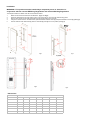
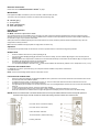
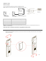
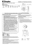
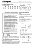
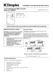
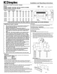
Installation and Operating Instructions
Campaver - Bathroom Radiator
Model No.s: CMV1200B/W/R, CMV1600B/W/R
July 2006—Issue 2
Dimensions (mm)
Model
Height (A)
Width + rails (B)
Depth + rails (C)
CMV1200B
1202
352 + 54
113 + 67
CMV1600B
1502
427 + 54
113 + 67
CMV1200W
1202
352 + 54
113 + 67
CMV1600W
1502
427 + 54
113 + 67
CMV1200R
1202
352 + 54
113 + 67
CMV1600R
1502
427 + 54
113 + 67
THESE INSTRUCTIONS SHOULD BE READ CAREFULLY AND RETAINED FOR FUTURE REFERENCE
IMPORTANT SAFETY ADVICE
General Principle
WARNING- This product must be installed by a competent
person or electrician in conjunction with the current IEE
Wiring Regulations and relevant Building Regulations
The Campaver range of bathroom radiators combine the use of
multiple radiant element technology with an innovative and stylish
use of glass to provide the perfect balance of radiant and convected
heating for optimum comfort.
When using electrical appliances, basic precautions
should always be followed to reduce risk of fire, electrical
shock, and injury to persons including the following:
The highly efficient aluminium radiant element and thin surface
heating film work together to provide rapid warm up and even heat
distribution across the surface of the glass.
WARNING - THE SURFACES OF THIS HEATER CAN BE
HOT
Momentary contact with any part of the heater should not
cause injury. However, aged or infirm persons or young
children should not be left unsupervised in the vicinity of
the heater unless a suitable guard is fitted
This appliance is not intended for use by children or other
persons without assistance or supervision if their
physical, sensory or mental capabilities prevent them
from using it safely.
The Campaver range also incorporates a fan boost controlled by a
runback timer, which overrides the thermostat setting, for powerful
room heating and rapid towel drying.
•
•
•
•
•
•
DO NOT cover or obstruct the air inlet or air outlet
vents - only use the towel hangers for drying/airing
towels
DO NOT recess the unit in to a wall, as this will
cause overheating and potentially be a fire risk.
The wall bracket provided must be used for
installation
DO NOT use outdoors
DO NOT locate the radiator immediately below a
fixed socket outlet or connection box
This radiator is IP24 rated and therefore can be
installed in a bathroom but must be located so
switches and other controls cannot be touched by
a person using a bath or shower
Location
All Campaver radiators should be installed by an
electrician or competent person in strict accordance with the
current IEE Wiring Regulations and relevant Building Regulations
Class 1 appliances:
UK & Northern Ireland installations:
All Campaver radiators are IPX4 rated and can therefore be
installed in Zone 2 of a bathroom. These appliances are NOT
suitable for installation in Zone 0 or Zone 1. (see Fig.2)
Republic of Ireland installations:
All Campaver radiators are IPX4 rated and can therefore be
installed in Zone 3 of a bathroom. These appliances are NOT
suitable for installation in Zone 0, Zone 1 or Zone 2. (see Fig.2)
Fig.2
Technical Specification
Model
Radiant Output(W)
Fan Output (W)
Voltage
Current (Amps)
Weight (kg)
Casing Finish
Glass Finish
CMV1200W
600
600
230V~AC
5
16
White
White
CMV1600W
1000
600
230V~AC
7
22
White
White
CMV1200B
600
600
230V~AC
5
16
Black
Black
CMV1600B
1000
600
230V~AC
7
22
Black
Black
CMV1200R
600
600
230V~AC
5
16
White
Mirror
CMV1600R
1000
600
230V~AC
7
22
White
Mirror
Installation
WARNING—This product must be installed by a competent person or electrician in
conjunction with the current IEE Wiring Regulations and relevant Building Regulations
The Campaver bathroom radiator must be wall mounted as follows:
1.
2.
3.
4.
5.
Make sure the minimum clearances are adhered to (Fig.1 and Fig.2)
Place the wall bracket on the wall, making sure it is the correct way up, and mark the relevant fixing points
Drill the holes and secure the wall bracket with the appropriate fixing type for the wall
Using the 6 vertical hooks on the wall bracket, place the radiator over the hooks (1) and pull downwards to secure (2) (see Fig.3)
Pull the child lock knob downwards (1) and turn clockwise (2) until tight to lock in position (see Fig.4)
Fig.1
Fig.2
Fig.3
Fig.4
Dimensions
Model
CMV1200W
Dimensions in mm
A
B
C
D
E
F
G
1202
352
140
265
106
514
265
CMV1600W
1502
427
215
505
106
514
325
CMV1200B
1202
352
140
265
106
514
265
CMV1600B
1502
427
215
505
106
514
325
CMV1200R
1202
352
140
265
106
514
265
CMV1600R
1502
427
215
505
106
514
325
Electrical Connection
Please also refer to ‘IMPORTANT SAFETY ADVICE’ on page 1
IMPORTANT:
If the appliance is NOT connected to a pilot wire controller, isolate the black pilot wire
The wires in the mains lead are coloured in accordance with the following code:
N - Neutral (grey)
L - Live (brown)
E - Earth (yellow/green)
P - Pilot Wire (black)
Pilot Wire Connection
IMPORTANT
Do NOT connect the pilot wire to earth
Care should be taken with the installation of the pilot wire(s) as when switching to background (setback) they become energised at 240V
although only at a current of 1mA. In every case a suitable means of isolation must be provided for the pilot wire and marked to indicate that
two sources of supply may be present at the heater.
Where pilot wires are installed separately from the heater final sub-circuit they should be protected, double insulated and carry their own
integral earth continuity conductor.
Note: Pilot wire installations are appropriate for single phase connection only
Operation
The Campaver incorporates simple to use electronic controls to provide maximum comfort and energy saving benefits.
Radiant Heat
1.
2.
3.
4.
Press the ON/OFF switch to the ‘I’ position (see Fig.4 - A)
Turn the thermostat dial (E) (see Fig.5) clockwise to the maximum setting, the neon indicator (F) will light to show the front panel is
starting to heat
Once the desired room temperature is achieved, turn the thermostat dial slowly anti-clockwise until the indicator (F) is no longer lit and
the radiator will automatically maintain the set temperature.
The thermostat dial (E) offers a frost protection setting.
Turn the thermostat dial ant-clockwise to the symbol and the radiator will automatically maintain a room temperature of 7ºC (+/-3ºC)
Fan boost and runback timer
For additional room heat or rapid towel drying, the Campaver bathroom radiator incorporates a runback timer
controlled fan boost.
NOTE: The fan boost will only operate with the runback timer control
Fan boost and runback timer
1.
2.
3.
4.
5.
Press the runback timer dial (C), the digital display (B) will show a preset time of 20 minutes and the fan boost will start to blow hot air
from the front base of the radiator upwards
To adjust the amount of time you want the fan boost to run, turn the runback timer dial anti-clockwise to decrease the time and
clockwise to increase the time (0-120 minutes maximum)
The digital display will countdown from the time selected to zero. Once the digital display reaches zero, the fan boost will automatically
switch off.
To switch off the fan boost manually, press the runback timer dial (C).
To save the desired time setting for the runback timer, press and hold the runback timer dial (C) for 3 seconds.
When the runback timer is switched off and on again the digital timer will display the new run back time as its default setting.
NOTE: When the runback timer is activated all three heat sources (both radiant elements and fan boost) will operate at
maximum heat output and will override the thermostat setting until the runback timer reaches zero.
Run back timer countdown display
Run back timer control dial
Filter saturation indicator
Thermostat dial (radiant heat only)
Heating indicator
Fig.4
Fig.5
Operation Contd.
Pilot wire control
Unscrew the metal receiver sleeve from the back of the radiator (see Fig.6)
NOTE: Do NOT remove the receiver sleeve if a slot in programmer is not to be used
RX9911
Single zone Pilot
Wire programmer
or
or
RXPW4 - Pilot Wire
4 zone controller
(no receiver required)
Fig.6
RXMBS4 Mains BorneSignalling
4 zone controller
RX9913
Mains Borne Signalling Receiver
Mode
Function (Radiant Elements Only)
Comfort / On
Heater functions at thermostat setting
Background (Setback)
Heater functions at 3.5ºC below thermostat setting
Off
No heat output
Frost protection
Heater functions at 7°C (+/-3ºC)
NOTE: Pilot wire and MBS controllers only control the radiant elements. If the runback timer is in use the fan boost will continue to run
regardless of the mode selected.
Please also refer to individual instructions for programmers and receivers
Assembly of towel rail(s)
1.
Place the rail above the radiator and push firmly in to the two slots at the rear of the radiator; there are three sets of slots for different
height options (see Fig.7)
Fig.7
Filter
Cleaning the filter
When the filter requires cleaning the ‘Filter’ neon indicator will light (see Fig.10a)
1.
2.
3.
4.
5.
First turn the child lock knob anti-clockwise (1) and lift the knob upwards (2) (see Fig.8)
Gently pull the right hand side of the radiator outwards (see Fig.9)
Slide out the filter towards you (see Fig. 9)
Wash the filter in warm soapy water and replace
Ensure the child lock is engaged (see also Fig.4 in the ‘Installation’ section on page 2)
Fig.10a
Fig.10b
Fig.8
Fig.9
Cleaning
IMPORTANT:
•
•
•
Never clean the appliance whilst it is hot, always allow the product to cool sufficiently.
Do NOT use abrasive cleaning products
Always wait for the appliance to dry before switching it on again
Clean the casing of the product with a sponge and soapy water.
Clean the glass front panel with a soft cloth and glass cleaner solution
After Sales Service
Your product is guaranteed for two years from the date of purchase.
Within this period, we undertake to repair or exchange this product free of charge (subject to availability) provided it has been installed and
operated in accordance with these instructions. Your rights under this guarantee are additional to your statutory rights, which in turn are not
affected by this guarantee.
Should you require after sales service you should contact our customer services help desk on 0870 727 0101. It would assist us if you can
quote the model number, date of purchase, and nature of the fault at the time of your call. The customer services help desk will also be able
to advise you should you need to purchase any spares.
Please do not return a faulty product to us in the first instance as this may result in loss or damage and delay in providing you with a
satisfactory service.
Please retain your receipt as proof of purchase.
Glen Dimplex UK Ltd
Millbrook House
Grange Drive
Hedge End
Southampton
Customer Help Line
Tel: (0870) 727 0101 (8am-6pm Mon-Fri; 8:30am-1pm Sat.)
Fax: (0870) 727 0102
E-mail: [email protected]
Web-site: www.dimplex.com
Republic of Ireland Tel: 01 842 4833
[C] Glen Dimplex UK Limited
All rights reserved. Material contained in this publication may not be reproduced in whole or part, without prior permission in writing from Glen Dimplex UK Limited.