1
Panelled internal walls
DO NOT USE 30MM SPACER ON INSIDE OF RADIATOR.
If possible, locate the studding and use No. 10 size
woodscrews. Where it is not possible to locate the studding
use type M5 Rawlplug INTERSETS on securely fastened
plasterboard panelling. For other wall materials the wall
panel manufacturer should be consulted for details of
suitable wall fixing devices.
USE ONLY EXTERNALLY - SEE FIG. 11A.
NOTE: UNDER NO CIRCUMSTANCES SHOULD THESE
SCREWS BE REMOVED WITHOUT FIRST REMOVING
12.
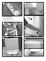
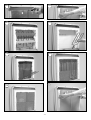
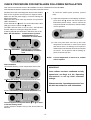
Remove the inner front panel by removing the
screws along its top edge Fig. 12A. Carefully lift the
bottom of the front inner panel out of the retaining flange
at the base of the radiator, Fig 12B and remove the internal
packaging, Fig. 12C taking care not to damage the insulation
attached.
ALL ENERGY RETENTION CELLS FROM THE RADIATOR
10F
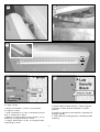
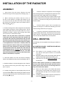
Once both sides have been successfully positioned
screw the radiator flush to the wall Fig. 10F.
Do not fully tighten these screws until the core has
been loaded into the radiator as some settling of the
radiator may occur.
13.
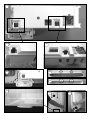
Lift out the elements from the base insulation and
rotate forwards. Fig. 13.
DO NOT DISCONNECT THE TERMINALS
11.
SKIRTING BOARD TALLER THAN 100MM
14.
Carefully fit the bottom row of the back layer of
energy retention cells, placing the two end cells in position
first with the flat side toward the back. Fit the top row of
cells also with the recess toward the element. Fig. 14
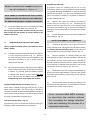
Use the 10mm and 30mm spacers provided (2 x 10mm
and 2 x 30mm)
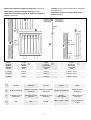
11A
11B
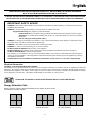
If the skirting board is taller than 100mm, the radiator
is to be mounted as shown in fig 11A. Remove
the wall mounting bracket and reassemble in the
alternative orientation to give a greater spacing
distance from the wall.
15.
Refit the elements by carefully feeding the tails
down through the hole in the base insulation, ensuring the
tab is pointing forward. Fit the front layer of cells with the
flat side toward the front of the radiator. Ensure that the tab
on the element is captured below the bottom row of cells
and that the element is vertical. Fig. 15A & 15B.
Place the 30mm spacer to the outside of the radiator
and the 10mm to the inside. Drill the holes as detailed
in Section 10. Carefully guide the radiator towards
the drilled hole. When in position screw part way
to the wall to secure the radiator as in Section 10,
remembering not to fully tighten the screws.
16.
Replace the inner front complete with insulation by
locating its bottom edge behind the front lip of the chassis
and inserting the retaining screws along the top and both
sides. Fig. 16.
17.
Check that the screws securing the radiator to the
wall have been fully tightened. It is essential that all screws
are replaced to ensure earth continuity.
Solid brick/High density block walls - Fig. 11C
These must be drilled and plugged with the No. 10 size
plastic inserts provided. The correct size of drill (8mm)
should be used and the hole should be drilled to a depth of
15mm greater than the length of the plastic insert so that
the fixing is made below the plaster layer.
Once installed DO NOT attempt
to reposition the radiator without
first unloading the energy retention
cells and obtaining the services of a
competent electrician.
Low density block walls - Fig 11d
A special fixing, such as Unifix LB70 should be employed,
following closely the manufacturers instructions.
- 10 -