1
Apollo MX20
Multi-Function Display
Installation Manual
June 2003
560-1025-07
2003 by UPS Aviation Technologies, Inc. All rights reserved.
Printed in the USA.
This document and the information disclosed herein are proprietary information of UPSAT. Neither this
document nor the information contained herein shall be transmitted, reproduced, copied, or disclosed in
any form or by any means without the written authorization of UPSAT.
The information disclosed herein includes trade secrets and confidential business and/or financial
information and falls within exemption (b) (4) of 5 USC 552 (FOIA) and the prohibitions of 18 USC
1905.
UPS Aviation Technologies® is a registered trademark of United Parcel Service of America, Inc.
UPS Aviation Technologies, Inc.
PO Box 13549
Salem, OR 97309
2345 Turner Rd., SE
Salem, OR 97302
USA
Phone (503) 581-8101
1-800-525-6726
In Canada 1-800-654-3415
FAX (503) 364-2138
www.upsat.com
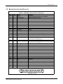
HISTORY OF REVISIONS
Part No.
560-1025-01
Revision
---
560-1025-02
--
560-1025-02
a
560-1025-02
560-1025-02
560-1025-03
b
c
--
560-1025-04
--
560-1025-05
560-1025-05
560-1025-06
560-1025-07
-a
---
Date
Description
11/1/99 Initial Release.
11/11/99 Updated installation package contents and equipment
mounting information.
1/17/00 Added the MX20 configuration procedure, expanded post
installation checkout procedures, added Appendix A.
4/3/00 Clarified unit installation position. Corrected wiring diagram.
Incorporated changes for software version 1.2.
7/25/00 Incorporated changes for software version 2.0.
10/3/00 Added mounting tube considerations
12/1/00 Changes for class and category in environmental qualifications
and new ADS-B messages.
7/18/01 Changes to mounting tube and environmental qualifications
for helicopters.
4/12/02 Added I/O board option and SW to support traffic and radar.
6/12/02 Added JTSO
11/13/02 Added landmark support for the TAWS8000
6/18/03 Changes for SW Ver 5.0. Radar and WSI.
ORDERING INFORMATION
To receive additional copies of this publication, order part # 560-1025-07, Apollo MX20 MultiFunction Display Installation Manual.
OTHER PUBLICATIONS
GX50/60 Installation Manual, P/N 560-0959
WX-500 Installation Manual, Goodrich Avionics P/N 009-11500-001
SKY899 Installation Manual, Goodrich Avionics P/N 009-11900-001
RDR2000 Installation Manual, Allied Signal P/N 006-00643-0004
9900B Installation Manual, Ryan TCAD P/N 32-2301
9900BX Installation Manual, Ryan TCAD P/N 32-2351
WSI InFlight Installation Manual, WSI P/N 305427-00
GTX330, GTX330D Transponder Manual, Garmin P/N 190-00207-02 Rev. A
End User License Agreement (“EULA”)
Refund. If you do not agree to the terms of this EULA, UPS Aviation Technologies and Microsoft are
unwilling to license the MX20 and its Operating System to you. In such event, you may not use or copy
the Licensed Product, and you should promptly contact UPS Aviation Technologies for instructions on
return of the unused product(s) for a refund.
Client Access Licenses. If you use the MX20 Operating System to access or utilize the services or
functionality of Microsoft Windows NT Server (all editions) or use the MX20 Operating System to
permit workstation or computing devices to access or utilize the services or functionality of Microsoft
Windows NT Server, you may be required to obtain a Client Access License for the MX20 Operating
System and/or each such workstation or computing device.
No Warranties. Except as expressly provided in the limited warranty section, the MX20 and its operating
system are provided to you “as is” without warranty of any kind, either expressed or implied, including,
but not limited to, warranties of noninfringement, merchantability, and/or fitness for a particular purpose.
The entire risk of the quality and performance of the software is with the user.
No Liability for Consequential Damages. UPS Aviation Technologies and/or UPS Aviation
Technologies’ software suppliers shall not be held liable for any damages suffered or incurred by you
(including, but not limited to, general, special, consequential or incidental damages including damages for
loss of business profits, business interruption, loss of business information and the like), arising from or in
connection with the delivery, use, or performance of the software.
Customer Remedies. UPS Aviation Technologies’ and UPS Aviation Technologies suppliers’ entire
liability and your exclusive remedy shall be, at UPS Aviation Technologies’ option, either (a) return of
the price paid, or (b) repair or replacement of the MX20 and its operating system that does not meet the
above Limited Warranty and which is returned to UPS Aviation Technologies with a copy of your
receipt. This Limited Warranty is void if failure of the MX20 or its operating system has resulted from
accident, abuse, or misapplication. Any replacement MX20 and its operating system will be warranted for
the remainder of the original warranty period or thirty (30) days, whichever is longer.
Limitations on Reverse Engineering, Decompilation and Disassembly. You may not reverse engineer,
decompile, or disassemble the MX20 or its operating system, except and only to the extent that such
activity is expressly permitted by applicable law notwithstanding this limitation.
Separation of Components. The MX20 and its operating system are licensed as a single product. Its
component parts may not be separated for use on more than one MX20.
Single Embedded System. The MX20 and its operating system are licensed with the MX20 as a single
integrated product. The MX20 operating system may only be used with the MX20 as set forth in these
licensing terms.
U.S. Government Restricted Rights Legend: This Software is furnished with Restricted Rights. Use,
duplication, or disclosure of the Software by the U.S. Government is subject to the restrictions as set forth
in subparagraph (c)(1)(ii) of the Rights in Technical Data and Computer Software clause at 48 C.F.R. Sec.
252.227-7013 or in subparagraphs (c)(1) and (2) of the Commercial Computer Software-Restricted Rights
clause at 48 C.F.R. Sec. 52-227-19, as applicable. UPS Aviation Technologies, 2345 Turner Road S.E.,
Salem, OR 97302.
Table of Contents
TABLE OF CONTENTS
1
INTRODUCTION.............................................................................................................................. 1
1.1
ABOUT THIS MANUAL ..................................................................................................................... 1
1.2
SYSTEM DESCRIPTION ..................................................................................................................... 1
1.3
REGULATORY COMPLIANCE ............................................................................................................ 3
1.4
UNPACKING THE EQUIPMENT .......................................................................................................... 4
1.5
PACKAGE CONTENTS ....................................................................................................................... 4
1.6
SPECIAL TOOLS REQUIRED .............................................................................................................. 6
1.7
LICENSE REQUIREMENTS ................................................................................................................. 6
1.8
OPERATING INSTRUCTIONS.............................................................................................................. 6
1.8.1
1.9
MX20..........................................................................................................................................................6
EXTERNAL DATA SOURCE COMPATIBILITY .................................................................................... 6
2
INSTALLATION ............................................................................................................................... 7
2.1
PRE-INSTALLATION INFORMATION .................................................................................................. 7
2.2
INSTALLATION OVERVIEW .............................................................................................................. 7
2.3
INSTALLATION CONSIDERATIONS .................................................................................................... 7
2.3.1
2.3.2
2.3.3
2.3.4
2.3.5
2.3.6
2.4
2.5
EXISTING SENSORS ......................................................................................................................................7
MOUNTING CONSIDERATIONS......................................................................................................................7
MINIMUM SYSTEM CONFIGURATION .........................................................................................................11
AIR CIRCULATION .....................................................................................................................................11
COMPASS SAFE DISTANCE .........................................................................................................................11
VIEWING ANGLE........................................................................................................................................11
EQUIPMENT MOUNTING ................................................................................................................. 12
ELECTRICAL CONNECTIONS .......................................................................................................... 14
2.5.1
2.5.2
2.5.3
2.5.4
2.5.5
2.5.6
2.5.7
2.6
2.7
MX20 BASIC DATA PORT CONFIGURATION ..............................................................................................15
MX20 I/O DATA PORT CONFIGURATION ...................................................................................................16
DATA CARD ...............................................................................................................................................16
PLACARD ...................................................................................................................................................17
POWER .......................................................................................................................................................17
ELECTRICAL LOAD ANALYSIS ...................................................................................................................17
SAMPLE WIRING DIAGRAMS ......................................................................................................................18
WEIGHT AND BALANCE ................................................................................................................. 24
CONFIGURING THE MX20 & MX20 I/O......................................................................................... 25
2.7.1
2.7.2
2.7.3
2.7.4
2.8
ENABLE/DISABLE FUNCTIONS ...................................................................................................................26
EXTERNAL DATA SOURCE .........................................................................................................................27
EXTERNAL DATA SOURCE FOR THE MX20 I/O ..........................................................................................29
MISCELLANEOUS SETUP OPTIONS .............................................................................................................30
MX20 POST INSTALLATION CHECKOUT ........................................................................................ 32
2.8.1
2.8.2
2.8.3
2.8.4
2.8.5
2.8.6
2.8.7
2.8.8
2.8.9
2.8.10
2.8.11
2.8.12
2.8.13
MOUNTING / WIRING CHECK .....................................................................................................................32
SOFTWARE AND DATABASE TEST ..............................................................................................................32
EXTERNAL DATA SOURCE TESTS ..............................................................................................................32
EMI/RFI TEST ...........................................................................................................................................34
ALTITUDE TEST .........................................................................................................................................35
COMPASS TEST ..........................................................................................................................................35
STORMSCOPE INTERFACE TEST ..................................................................................................................35
SKYWATCH INTERFACE TEST ....................................................................................................................35
RYAN TCAD INTERFACE TEST ..................................................................................................................36
RADAR CONFIGURATION & CHECKOUT PROCEDURES ........................................................................36
LANDMARK TAWS8000 AND KGP560 CHECKOUT PROCEDURE..........................................................39
GARMIN GTX330 CHECKOUT PROCEDURE ..........................................................................................40
WSI INFLIGHT CHECKOUT PROCEDURE ...............................................................................................40
Apollo MX20 Installation Manual
i
Table of Contents
3
SPECIFICATIONS .......................................................................................................................... 43
3.1
MX20 FEATURES ........................................................................................................................... 43
3.1.1
3.1.2
3.1.3
3.1.4
3.1.5
3.1.6
3.1.7
3.1.8
3.1.9
3.1.10
3.1.11
3.1.12
3.1.13
3.1.14
3.2
DISPLAY .................................................................................................................................................... 43
USER INTERFACE ...................................................................................................................................... 43
EXPANSION/INTERNAL ARCHITECTURE..................................................................................................... 43
POSITION SOURCE ..................................................................................................................................... 43
ELECTRICAL .............................................................................................................................................. 43
AVIONICS OUTPUTS .................................................................................................................................. 44
AVIONICS INPUTS ...................................................................................................................................... 44
AVIONICS OUTPUTS (I/O MODEL)............................................................................................................. 44
AVIONICS INPUTS (I/O MODEL) ................................................................................................................ 44
SERIAL INTERFACE DATA SOURCES ..................................................................................................... 44
PHYSICAL SPECIFICATIONS................................................................................................................... 44
ENVIRONMENTAL SPECIFICATIONS....................................................................................................... 45
TSO AUTHORIZATIONS ........................................................................................................................ 45
INTERNAL GPS RECEIVER PERFORMANCE ........................................................................................... 46
REAR CONNECTOR PINOUTS .......................................................................................................... 47
4
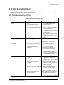
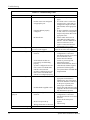
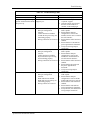
TROUBLESHOOTING................................................................................................................... 51
4.1
TROUBLESHOOTING GUIDE ............................................................................................................ 51
4.2
INTEGRATION TROUBLESHOOTING PROCEDURE ............................................................................ 54
4.3
CONTACTING THE FACTORY FOR ASSISTANCE .............................................................................. 56
5
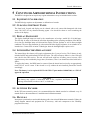
CONTINUED AIRWORTHINESS INSTRUCTIONS ................................................................. 57
5.1
EQUIPMENT CALIBRATION ............................................................................................................. 57
5.2
CLEANING THE FRONT PANEL ........................................................................................................ 57
5.3
DISPLAY BACKLIGHT ..................................................................................................................... 57
5.4
LITHIUM BATTERY REPLACEMENT ................................................................................................ 57
5.5
ALTITUDE ENCODER ...................................................................................................................... 57
5.6
MANUALS ....................................................................................................................................... 57
6
ENVIRONMENTAL QUALIFICATIONS.................................................................................... 59
APPENDIX A – I/O SPECIFICATIONS................................................................................................ 61
6.1
MOVING MAP INPUT ...................................................................................................................... 61
6.2
BINARY NEAREST LIST DATA (WHEN EXTENDED DATA IS ENABLED ONLY) ............................... 62
6.3
FLIGHT PLAN WAYPOINT TYPES (WHEN EXTENDED DATA IS ENABLED ONLY)........................... 64
6.4
ALTITUDE ENCODER/CONVERTER INPUT ...................................................................................... 66
6.5
STORMSCOPE INPUTS ..................................................................................................................... 67
LIST OF TABLES
TABLE 1 - INSTALLATION PACKAGE CONTENTS ........................................................................................... 5
ii
Apollo MX20 Installation Manual
Table of Contents
TABLE 2 - PREFERRED DATA PORT CONFIGURATIONS ............................................................................... 15
TABLE 3 – MX20 I/O DATA PORT CONFIGURATIONS ................................................................................ 16
TABLE 4 – UNIT POWER LOADS .................................................................................................................. 17
TABLE 5 - UNIT WEIGHTS ........................................................................................................................... 24
TABLE 6 – UNIT POWER LOADS .................................................................................................................. 43
TABLE 7 - UNIT WEIGHTS ........................................................................................................................... 45
TABLE 8 - MX20 REAR PANEL CONNECTOR PINOUT (J1) ......................................................................... 47
TABLE 9 - MX20 I/O CONNECTOR PINOUT (J2) ......................................................................................... 48
TABLE 10 - TROUBLESHOOTING GUIDE ...................................................................................................... 51
TABLE 11 - MOVING MAP ASCII NAVIGATION DATA ............................................................................... 61
TABLE 12 - NEAREST WAYPOINT LIST DATA ............................................................................................. 62
TABLE 13 - MOVING MAP BINARY ROUTE DATA....................................................................................... 63
TABLE 14 - FLIGHT PLAN WAYPOINT TYPE ............................................................................................... 64
TABLE 15 - ALTITUDE INPUT DATA ............................................................................................................ 66
LIST OF ILLUSTRATIONS
FIGURE 1 – MX20 SYSTEM BLOCK DIAGRAM .............................................................................................. 2
FIGURE 2 - MX20 I/O SYSTEM BLOCK DIAGRAM ........................................................................................ 2
FIGURE 3 - MX20 FRONT PANEL DESCRIPTION ............................................................................................ 3
FIGURE 4 - COCKPIT PANEL CONFIGURATION FOR A LARGE PANEL ............................................................ 8
FIGURE 5 - COCKPIT PANEL CONFIGURATION FOR A SMALL PANEL ............................................................ 8
FIGURE 6 - SAMPLE GX60 & MX20 MOUNTING .......................................................................................... 9
FIGURE 7 - ALTERNATE MX20 MOUNTING CONFIGURATION ...................................................................... 9
FIGURE 8 - MX20 UNIT DIMENSIONS ......................................................................................................... 10
FIGURE 9 - MX20 MOUNTING TUBE ASSEMBLY DIMENSIONS ................................................................... 11
FIGURE 10 - MX20 TYPICAL REAR PANEL WIRING CONNECTIONS ........................................................... 13
FIGURE 11 - DATA PORT LOCATION ........................................................................................................... 14
FIGURE 12 – PREFERRED DATA PORT DESCRIPTION .................................................................................. 15
FIGURE 13 –DATA I/O PORT DESCRIPTION................................................................................................. 16
FIGURE 14 - SAMPLE SYSTEM WIRING DIAGRAM (INTERNAL GPS VERSION) WITH UAT ........................ 18
FIGURE 15 - SAMPLE SYSTEM WIRING DIAGRAM (NO INTERNAL GPS VERSION) WITH WX500 .............. 19
FIGURE 16 - SAMPLE SYSTEM WIRING DIAGRAM FOR TCAD AND STORMSCOPE ..................................... 20
FIGURE 17 - SAMPLE SYSTEM WIRING DIAGRAM I/O MODEL WITH RADAR, GOODRICH SKYWATCH, AND
WSI INFLIGHT RECEIVER .................................................................................................................. 21
FIGURE 18 - SAMPLE SYSTEM WIRING DIAGRAM OF MX20 I/O WITH LANDMARK TAWS....................... 22
FIGURE 19 - SAMPLE SYSTEM WIRING DIAGRAM OF MX20 I/O WITH GARMIN GTX330 ......................... 23
FIGURE 20 - SAMPLE SYSTEM WIRING DIAGRAM OF MX20 I/O WITH KGP-560....................................... 24
FIGURE 21 - MOVING MAP DATA OUTPUT (EXTENDED DATA DISABLED) ................................................ 64
FIGURE 22 - MOVING MAP DATA OUTPUT (EXTENDED DATA ENABLED) ................................................. 65
FIGURE 23 - ALTITUDE DATA INPUT........................................................................................................... 67
Apollo MX20 Installation Manual
iii
Table of Contents
NOTES
iv
Apollo MX20 Installation Manual
Introduction
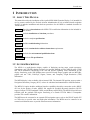
1 INTRODUCTION
1.1 ABOUT THIS MANUAL
This manual describes the installation of the Apollo MX20 Multi-Function Display. It is intended for
use by persons certified by the Federal Aviation Administration (FAA) to install aircraft navigation
devices. It includes installation and checkout procedures for the MX20 to standards described in
14CFR Part 43.
Section 1
Provides an introduction to the MX20. TSO certification information is also included in
this section.
Section 2
Includes installation and checkout procedures.
Section 3
Includes complete specifications.
Section 4
Includes troubleshooting information.
Section 5
Includes continued airworthiness instructions requirements.
Section 6
Includes the environmental qualification form.
Appendix A
Includes I/O specifications.
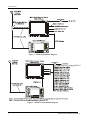
1.2 SYSTEM DESCRIPTION
The MX20 is a multi-function display capable of displaying moving maps, terrain awareness,
obstructions, and VFR/IFR charting functions. An optional datalink provides ADS-B traffic, FIS-B
and TIS-B information. Interfacing to the WX-500 provides lightning strike information on the
display. Interfacing to the WSI Inflight sensor provides Nexrad images, graphic and text METARs,
graphic and text TAFs, EchoTops, Sigmet, Airmet, and Temporary Flight Restriction (TFR)
information.
The MX20 display is also available with an internal GPS. The internal GPS position source permits a
Navigation Uncertainty Category (NUC) value to be calculated and transmitted for ADS-B broadcast.
The MX20 I/O option includes additional interface capabilities that allow connection to the ARINC
453 bus for the display of radar, ARINC 429 support for Goodrich Skywatch interfaces, RS-232
support for Ryan TCAD, Landmark TAWS, and the Honeywell KGP560. The MX20 I/O model is not
available with the optional GPS engine. Interfacing to a Garmin GTX330 Mode S Transponder
provides TIS-A traffic information.
The MX20 must be connected to an external GPS navigation source, such as the UPSAT Apollo GX
or CNX-series, to provide route and flight plan information. The MX20 must be connected to an
external serial altitude source to provide terrain awareness information.
Apollo MX20 Installation Manual
1
Introduction
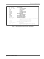
Figure 1 – MX20 System Block Diagram
Figure 2 - MX20 I/O System Block Diagram
2
Apollo MX20 Installation Manual
Introduction
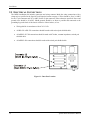
Figure 3 - MX20 Front Panel Description
1.3 REGULATORY COMPLIANCE
The MX20 is designed and tested to meet the following TSOs when connected to the appropriate
equipment:
•
•
•
•
•
•
FAA TSO-C63c/JTSO 2C63c
FAA TSO-C110a/JTSO-C110a
FAA TSO-C113/JTSO-C113
FAA TSO-C118/JTSO-C118
FAA TSO-C147
FAA TSO-C151a
Airborne Weather Radar
Passive Thunderstorm Detection (Goodrich WX500)
Multi-purpose Electronic Display
Traffic Alert and Collision Avoidance (TCAS I)
Traffic Advisory System (TAS)
Terrain Awareness and Warning System (TAWS)
The MX20 software is designed and tested to RTCA/DO-178B, levels C and D.
NOTE
Unauthorized changes or modifications to the MX20 will void the compliance to required
regulatory agencies and authorization for continued equipment usage.
“The conditions and tests required for TSO approval of this article are minimum performance standards.
It is the responsibility of those desiring to install this article either on or within a specific type or class of
aircraft to determine that the aircraft installation conditions are within the TSO standards. If not within
the TSO standards, the article may be installed only if the applicant documents further evaluation for an
acceptable installation and it is approved by the Administrator.”
Apollo MX20 Installation Manual
3
Introduction
"The conditions and tests required for TSO/JTSO approval of this article are minimum performance
standards. It is the responsibility of those installing this article either on or within a specific type or class
of aircraft to determine that the aircraft installation conditions are within the TSO/JTSO standards. The
article may be installed only if the installation is performed in accordance with Part 43 or the applicable
airworthiness requirements.”
1.4 UNPACKING THE EQUIPMENT
Carefully unpack the equipment. Visually inspect the package contents for any evidence of shipping
damage. Retain all shipping containers and packaging material in case reshipment is necessary.
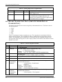
1.5 PACKAGE CONTENTS
As shipped from the UPS Aviation Technologies factory, the MX20 Installation package includes
most necessary items for installation other than supplies normally available at the installation shop.
The items included in the package are listed in Table 1.
4
Apollo MX20 Installation Manual
Introduction
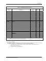
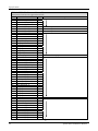
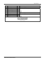
Table 1 - Installation Package Contents
Part #
Unit
430-0270-0xx
430-0270-5xx
430-0270-6xx
430-0270-7xx
115-0007-00
162-1008
162-1060
162-1577*
202-0001
204-0037
204-2100
220-0637
240-0615
224-0404
245-0027*
310-0429-xx
998-0048
Description
Apollo MX20 Multifunction Display with GPS
Apollo MX20 Multifunction Display without GPS
Apollo MX20 I/O Traffic Multifunction Display
Apollo MX20 I/O Traffic/Radar Multifunction Display
MX20 Installation Kit
GPS 1575 MHz 2:1 splitter
Right angle coax plug
TNC Connector
37-pin d-Sub
Cable tie
Edge grommet
Shoulder bushing
6-32 Wing nut
#6 Washer
4-40 x 1/4 SS flat head Phillips machine screw
Crimp contact for d-sub, 20 to 24 AWG wire
MFD Mounting Tube
3/32" hex driver
MX20 I/O Installation Kit
62-pin d-Sub, high density
Crimp contact for high density d-sub, 22 to 30 AWG wire
Manual Kit
MX20 Installation Guide
MX20 User's Guide
MX20 Quick Reference Guide
STC Kit (AFM & MDL)
160-0138
245-0059
564-0076-0xx
560-1025-xx
560-1026-xx
561-0263
564-0078-0xx
Notes:
* Pin has a barrel over the contact. Use ITT Cannon tools.
Quantity w/o
GPS
424-0751
Quantity
w/ GPS
Quantity
w/ I/O
424-0753
1
1
1
1
1
4
6"
1
2
2
30
1
1
1
1
1
1
1
1
1
3
1
4
6"
2
1
2
2
30
1
1
1
2
2
40
1
1
1
1
1
1
1
1
20
1
1
1
1
1
1
4
6"
Other Required Materials
The MX20 equipment is intended for use with standard aviation accessories. See section 1.9 for a list
of compatible equipment. The following items are required for the installation:
• Compatible position locating source, such as: Apollo GX50/55/60/65 GPS receiver, or
Apollo CNX-series receiver
• Compatible Serial Altitude Encoder
Apollo MX20 Installation Manual
5
Introduction
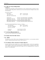
1.6 SPECIAL TOOLS REQUIRED
Crimp Tool
A crimp tool meeting MIL specification M22520/1-01 and a positioner/locator are required to ensure
consistent, reliable crimp contact connections for the rear d-sub connectors. Examples of these tools
are shown below:
For pin P/N 245-0027
ITT Cannon
1851 E. Deere Ave.
Santa Ana, CA 92705-6500
Phone (714) 261-5300
Fax
(714) 575-8324
Insertion tool:
ITT part # 274-7006-000 (Desc. CIET-20HD)
Regular duty Crimp tool:
ITT part # 995-0001-585 (Desc. M22520/1-01)
Regular duty Locator tool:
ITT part # 995-0001-244 (Desc. TH25)
Heavy duty Crimp tool: ITT part # 995-0001-584 (Desc. M22520/2-01)
Heavy duty Locator tool:
ITT part # 995-0001-604 (Desc. M22520/2-08)
For pin P/N 245-0059 (High Density Connector – I/O Only)
Astro Tool Corp
Phone (503) 642-9853
21615 SW TV Highway
Fax
(503) 591-7766
Beaverton, OR 97006
Crimp tool:
Positioner:
Astro Tool part # 615708
Astro Tool part # 616356
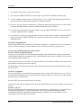
1.7 LICENSE REQUIREMENTS
There are no license requirements for the MX20.
1.8 OPERATING INSTRUCTIONS
1.8.1 MX20
The MX20 User's Guide, UPS Aviation Technologies P/N 560-1026-xx, covers operation and pilot
interface. The MX20 Quick Reference Guide is P/N 561-0263-xx.
1.9 EXTERNAL DATA SOURCE COMPATIBILITY
External serial data sources intended for use with the MX20 should be checked for compatibility
before installation. Devices from other manufacturers or unlisted models are supported if they adhere
to the interface specifications provided in this manual. The list of supported devices is located in
Section 3.1.10 of this manual.
6
Apollo MX20 Installation Manual
Installation
2 INSTALLATION
This section describes the installation of the MX20 including mounting, wiring, connections, and software
configuration. A post-installation checkout procedure is included at the end of this section.
2.1 PRE-INSTALLATION INFORMATION
Always follow good avionics installation practices per FAA Advisory Circulars (AC) 43.13-1B, 43.13-2A,
and AC 20-138, or later FAA approved revisions of these documents.
Follow the installation procedure in this section as it is presented for a successful installation. Read the
entire section before beginning the procedure. Prior to installation, consider the structural integrity of the
MX20 installation as defined in AC 43.13.2A, Chapter 1. Perform the post installation checkout before
closing the work area in case problems occur.
Complete an electrical load analysis in accordance with AC 43.13-1B, Chapter 11, on the aircraft prior to
starting modification to ensure aircraft has the ability to carry the MX20 load. Refer to Section 2.5.6 for
the power consumption of each MX20 mode of operation (heater on). Document the results of the
electrical load analysis on FAA Form 337.
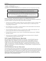
2.2 INSTALLATION OVERVIEW
A successful installation should start with careful planning including determination of mounting location
for the MX20, cable routing, and other required modifications. Once the mounting location has been
determined, prepare the mounting frames for installation. It may be easier to complete the wiring harness
and attach the connectors to the mounting frame before installing the mounting frame.
Carefully plan which external devices are to be connected to which MX20 ports observing the special
characteristics of ports 3 and 4.
2.3 INSTALLATION CONSIDERATIONS
2.3.1 EXISTING SENSORS
When the MX20 is installed with external sensors, these sensors must be installed with manufacturer's
data. This manual does not provide information for the installation of specific external sensors.
2.3.2 MOUNTING CONSIDERATIONS
The MX20 is designed to mount in the avionics stack in the aircraft instrument panel within view and
reach of the pilot. The MX20 must be located where the operator will have easy access to the controls and
adequate viewing of the display. The preferred location would minimize pilot head movement when
transitioning between looking outside of the flight deck and viewing and operating the MX20. Sample
diagrams of typical cockpit front panel views of the MX20 are shown in Figure 4 and Figure 5.
The standard package includes a mounting frame for ease of mounting, connections, and service of the
unit. Allow an additional one-inch clearance to the rear of the mounting frame for connectors and cables.
Mounting frame details are shown in Figure 6, Figure 7, Figure 8, and Figure 9. Use of mounting tube
P/N 310-0429-01, or later FAA approved revision, is recommended for all installations and is required for
helicopter installations.
The MX20 does not require external cooling. When mounting the MX20, leave a clearance of 1/8 to 1/4
inch between avionics to allow for air circulation.
Apollo MX20 Installation Manual
7
Installation
Figure 4 - Cockpit Panel Configuration for a Large Panel
Figure 5 - Cockpit Panel Configuration for a Small Panel
8
Apollo MX20 Installation Manual
Installation
Figure 6 - Sample GX60 & MX20 Mounting
Figure 7 - Alternate MX20 Mounting Configuration
NOTE
This configuration utilizes an angle bracket along each side of the mounting tube. The installer must
consider the structural integrity of the installation as defined in AC43.13.2a Chapter 1.
Apollo MX20 Installation Manual
9
Installation
Figure 8 - MX20 Unit Dimensions
NOTE
Use of mounting tube P/N 310-0429-01, or later FAA approved revision, is recommended for all
installations and is required for helicopter installations.
10
Apollo MX20 Installation Manual
Installation
Figure 9 - MX20 Mounting Tube Assembly Dimensions
Note: Use of mounting tube P/N 310-0429-01, or later FAA approved revision, is recommended for all
installations and is required for helicopter installations.
2.3.3 MINIMUM SYSTEM CONFIGURATION
The MX20 requires connections to the following equipment as a minimum, as appropriate for each unit:
• Power input
• Serial position input device (such as the Apollo GX60, Apollo CNX-series, or equivalent)
• Serial altitude encoder
The serial I/O requirements are located in Appendix A of this manual.
2.3.4 AIR CIRCULATION
No external cooling is required for the MX20. Newer units will have an internal fan installed. Previous
units may be modified to include an internal fan, if desired. No special provisions are required during
installation to accommodate the fan except to ensure the fan opening is not blocked.
2.3.5 COMPASS SAFE DISTANCE
After reconfiguring the avionics in the cockpit panel, if the MX20 is mounted less than seven inches from
the compass, recalibrate the compass and make the necessary changes for noting correction data.
2.3.6 VIEWING ANGLE
The MX20 shall be located such that the operator will have easy access to the controls and have adequate
view of the display. The MX20 may be adequately viewed from the primary pilot’s position when the
following minimums are met:
Up:
20 degrees off pilot’s eye center line
Apollo MX20 Installation Manual
11
Installation
Down:
Right:
Left:
30 degrees off pilot’s eye center line
50 degrees off pilot’s eye center line
50 degrees off pilot’s eye center line
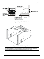
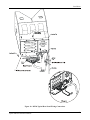
2.4 EQUIPMENT MOUNTING
Once the cable assemblies have been made, attach each connector to the rear connector mounting plate
and the mounting tube as illustrated in Figure 10. Route the wiring bundle as appropriate.
Use tie wraps to secure the cable to the rear connector plate to provide strain relief for the cable assembly
as shown in View A of Figure 10. Connect the shield grounds directly to the grounding lug.
Mounting Tube
Secure the mounting tube to the instrument panel structure using the sixteen screws. The AN507 6-32
screws have a 100o countersink head. The mating holes in the instrument panel structure must also be
countersunk to accept the screw head so that the screw head is flush with the inside surface of the
mounting tube.
CAUTION
Failure to properly countersink the mounting holes will result in damage to the MX20.
Mounting screw heads must not protrude into the mounting tube.
The mounting tube should be flush to the instrument panel and allow sufficient clearance for the back of the
bezel of the MX20 to mount flush to the mounting tube. Sufficient clearance must exist in the instrument
panel opening to allow ease of insertion and removal of the MX20.
CAUTION
If the back of the MX20 bezel does not mount flush to the mounting tube, the connector may
not engage fully.
An alternate mounting configuration can be accomplished using locally-fabricated L brackets. Make the
brackets from 20-24 T3 aluminum, 0.040", and form a 90o bend. When attaching the L brackets to the
mounting tube, screw heads must not protrude into the mounting tube.
Once the cable assemblies are complete and the connectors are attached to the mounting frame, install the
mounting frame assembly in the instrument panel. Be sure to use AN507 flat head screws so the unit will
slide in and out freely. Attach the front of the mounting frame to the instrument panel. Use support
brackets to attach the rear of the frame to the aircraft. Cable wiring to the mounting frame is shown in
Figure 10.
Slide the unit into the frame and hand-tighten the threaded screw shaft using the 3/32" hex driver provided in
the installation package. The unit will be pulled into the frame by the shaft and the connectors will fully
engage. The back of the bezel must only be flush to the mounting tube.
To remove the unit from the mounting frame, unscrew the screw shaft. The unit will be loosened and then
may be pulled from the frame. No special extraction tools are required.
12
Apollo MX20 Installation Manual
Installation
Figure 10 - MX20 Typical Rear Panel Wiring Connections
Apollo MX20 Installation Manual
13
Installation
2.5 ELECTRICAL CONNECTIONS
The MX20 installation kit includes connectors and crimp contacts. Make the crimp connections with a
crimp tool as specified in the Special Tools Required section on page 6. Wires should be 20 to 24 AWG
for the 37-pin connector and 22-30 AWG for the 62-pin connector, unless otherwise specified. Power and
ground wires should be 20 AWG. Shield grounds should be as short as possible and connected to the
grounding lug on the back of the chassis with wire of three inches, or less.
•
Wiring shall be in accordance with AC 43.13-1B.
•
All RS-422 or RS-232 connections should be made with twisted pair shielded cable.
•
All ARINC 453/708 connections should be made with 70 ohm, constant impedance, twisted pair
shielded cable.
•
All ARINC 429 connections should be made with twisted pair shielded cable.
Figure 11 - Data Port Location
14
Apollo MX20 Installation Manual
Installation
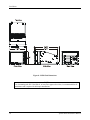
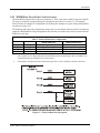
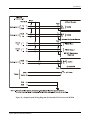
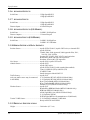
2.5.1 MX20 BASIC DATA PORT CONFIGURATION
The basic MX20 supports four I/O ports on connector J1. Three of the ports are RS232 and one is RS422.
The usage of each port is assigned during the configuration procedure (see section 2.7). The diagram
below provides an example of a configuration for the data ports. Samples of typical wiring configurations
are shown in section 2.5.7.
The following table shows the suggested port usage, however note that the software must be configured to
match the installed MX20 wiring configuration. Note that only one traffic source may be connected to the
MX20 I/O at one time.
Table 2 - Preferred Data Port Configurations
PORT 1
PORT 2
PORT 3
PORT 4
MX20 With GPS
GX50/60* or equivalent
Altitude Encoder* or option
Internal GPS**
UAT Datalink Radio or option
RS232
RS232
RS232
RS422
MX20 Without GPS
GX50/60* or equivalent
Altitude encoder* or option
SL30, or option
WX-500 or option
*
A GX-series unit running software version 3.2 or higher and enabled for extended mode and a CNX-series
unit is capable of receiving altitude data from the altitude encoder and passing the data to the MX20. This
configuration opens up an MX20 port for other options.
**
If the MX20 is configured with an internal GPS engine, Port 3 is not available for external connections.
Figure 12 – Preferred Data Port Description
Apollo MX20 Installation Manual
15
Installation
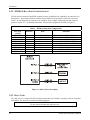
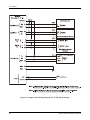
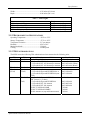
2.5.2 MX20 I/O DATA PORT CONFIGURATION
The I/O product variation of the MX20 supports an array of additional I/O capabilities on connector J2 as
shown below. Note that the hardware connected to the MX20 I/O ports must be connected as shown in
Table 3, as reconfiguration by software is not available. See the sample wiring diagrams and connector
pinouts in section 2.5.7 for detailed connections. One possible configuration is shown in Figure 13.
Table 3 – MX20 I/O Data Port Configurations
Port Type
(Count)
ARINC 453 (1)
ARINC 429 (1)
Discrete (1)
ARINC 429 (1)
Discrete (2)
J1 RS232
ARINC 453 (1)
ARINC 429 (1)
ARINC 429 (1)
Direction
Data
Input
Output
Output
Input
Output
Input
Input
Output
Input
Weather Radar Display
Weather Radar Control
Weather Radar Power
Traffic Data
Skywatch Mode Control
Ryan TCAD
Terrain Data
Terrain Control
Terrain Status
Allocation
ART2000 Radar, ART2100, RS-181A
ART2000 Radar, ART2100, RS-181A
ART2000 Radar, ART2100, RS-181A
Goodrich SKY497,SKY899, GTX330
Goodrich SKY497, SKY899, GTX330
Ryan 9900B/BX
Landmark, KGP560 TAWS
Landmark, KGP560 TAWS
Landmark TAWS, KGP560
Figure 13 –Data I/O Port Description
2.5.3 DATA CARD
The data card is a Compact Flash™ card that contains the NAV database, operating software, and other
information. The data card is required for MX20 operation.
CAUTION
Do not remove the data card with power on.
16
Apollo MX20 Installation Manual
Installation
2.5.4 PLACARD
The aircraft will have a placard identifying the MFD circuit breaker. The placard will be placed directly
adjacent to the respective breaker.
2.5.5 POWER
The power and fuse requirements for each external sensor are described in their respective installation
manuals. The MX20 will operate on voltages between 10 and 40 VDC. Install a five amp circuit breaker
for a 14 VDC aircraft and a three amp circuit breaker for a 28 VDC aircraft. Use separate wires for the
heater and CPU power inputs; one wire to each pin. Power and ground wires should be 20 AWG.
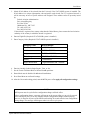
2.5.6 ELECTRICAL LOAD ANALYSIS
An electrical load analysis should be completed on each aircraft prior to installation in accordance with
AC 43.13-1B, Chapter 11. Use the following values for computation:
Table 4 – Unit Power Loads
Unit
MX20
MX20 with heater (1)
MX20 I/O
MX20 I/O with heater (1)
14 VDC
Typical
Max
2.0 A
3.0 A
3.0 A
4.0 A
2.5 A
3.5 A
3.5 A
4.5 A
28 VDC
Typical
Max
1A
1.5 A
1.5 A
2.0 A
1.25 A
1.75 A
1.75 A
2.25 A
Notes:
1. Heater element turns on below approximately 30oC.
Note: Circuits should be protected in accordance with guidelines in AC 43.13-1B, chapter 11, section 2,
paragraph 429. Power inputs should be across a minimum of all four specified input pins.
Apollo MX20 Installation Manual
17
Installation
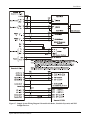
2.5.7 SAMPLE WIRING DIAGRAMS
Figure 14 - Sample System Wiring Diagram (Internal GPS Version) with UAT
18
Apollo MX20 Installation Manual
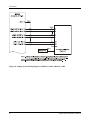
Installation
Figure 15 - Sample System Wiring Diagram (No Internal GPS Version) with WX500
Apollo MX20 Installation Manual
19
Installation
Figure 16 - Sample System Wiring Diagram for TCAD and Stormscope
20
Apollo MX20 Installation Manual
Installation
Figure 17 - Sample System Wiring Diagram I/O model with Radar, Goodrich Skywatch, and WSI
InFlight Receiver
Apollo MX20 Installation Manual
21
Installation
Figure 18 - Sample System Wiring Diagram of MX20 I/O with Landmark TAWS
22
Apollo MX20 Installation Manual
Installation
Figure 19 - Sample System Wiring Diagram of MX20 I/O with Garmin GTX330
Apollo MX20 Installation Manual
23
Installation
Figure 20 - Sample System Wiring Diagram of MX20 I/O with KGP-560
2.6 WEIGHT AND BALANCE
Weight and balance computation is required after the installation of the MX20. Follow the guidelines as
established in AC 43.13-1B, Chapter 10, section 2. Make appropriate entries in the equipment list
indicating items added, removed, or relocated along with the date accomplished. Include your name and
certificate number in the aircraft records. The following table identifies the weight of the new MX20
equipment.
Table 5 - Unit Weights
Unit
MX20 only, with GPS
MX20 only, without GPS
MX20 only, with I/O Option
MX20 mounting tray only
24
Weight
4.08 lb.
3.92 lb.
4.07 lb.
0.73 lb.
(1.85 kg)
(1.78 kg)
(1.85 kg)
(0.33 kg)
Apollo MX20 Installation Manual
Installation
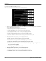
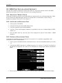
2.7 CONFIGURING THE MX20 & MX20 I/O
1. Turn on power to the MX20.
2. Immediately after the self-test is complete, press line select keys 1, 4, and 6 in sequence before
pressing any other keys (where 1 is the top line select key, 4 is the fourth key down, and 6 is the lower
most line select key). If other keys are pressed before or during this sequence, the MX20 will be in the
normal operational mode. To enter the install mode, turn off the MX20 and start again at step 1.
-1
-2
-3
-4
Line Select Keys
-5
-6
Function Key
Smart Keys
3. Press the function key until the INSTL function is present. If INSTL function is not found, restart the
unit. Carefully press line select keys 1, 4, and 6 in sequence. Do not press any other buttons before
pressing the 1, 4, 6 line select key sequence.
4. Select the INSTL function by pressing the smart key directly below the INSTL label. The
Enable/Disable Functions will be the first screen to appear.
NOTE
MX20 power must be cycled before configuration changes will take affect.
After a configuration change, a message will appear on the screen telling you to wait 30 seconds
before turning off power. You may continue to make configuration changes without pausing;
however, do not turn off power to the MX20 until waiting 30 seconds after the last configuration/
setting change. The message will disappear when it is safe to cycle power.
Apollo MX20 Installation Manual
25
Installation
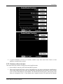
2.7.1 ENABLE/DISABLE FUNCTIONS
This menu allows the activation or deactivation of MX20 functions.
1. Ensure the Enable/Disable Functions page of the MX20 has the desired configuration. Modifications
can be made using the line select keys.
a. Enable Message to allow viewing of system messages.
b. Enable Custom Map to allow viewing of the Custom Map function.
c. Enable IFR En Route Map to allow viewing of the IFR Map function.
d. Enable VFR Sectional Map to allow viewing of the VFR Map function.
e. Enable the Split Screen function to allow viewing of two functions side by side.
2. Press the Next Page line select key to view additional functions.
a. Enable Traffic only if UAT, Skywatch, or GTX330 are installed.
b. Enable FIS Data Link only if a UAT or WSI InFlight system is installed.
c. Enable Flight Plan to allow viewing of flight plan route lines on the display.
d. Enable Terrain only if an altitude encoder is installed, either directly or through a navigation source,
or if a TAWS sensor is installed.
e. Enable Lightning only if WX-500 is installed.
3. Press the Next Page line select key to view additional functions.
a. Enable the System function to allow viewing of the System function.
b. Enable Radar only if a unit is an I/O model and interfaced to a radar unit.
26
Apollo MX20 Installation Manual
Installation
4. A typical installation will have all functions enabled except those noted above based on what
hardware is installed in the aircraft.
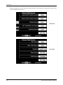
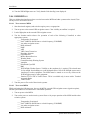
2.7.2 EXTERNAL DATA SOURCE
This menu allows the software to assign ports to the installed sensors.
1. Press the DATA smart key while still in the INSTL function.
2. Ensure the External Data Sources pages of the MX20 have the desired configuration. Modifications
can be made using the line select keys. Port allocations must match how the system is wired. Set port
source to None if the hardware is not installed. The Internal GPS Position Source, when present, must
always be configured to Port 3. If the altitude data is supplied from the GX model unit, the Altitude
Apollo MX20 Installation Manual
27
Installation
Source port must be set to the same port number that the GX model unit is connected to (such as Port
1 in the example shown below).
Main Menu
Next Page
28
Apollo MX20 Installation Manual
Installation
Next Page
2.7.3 EXTERNAL DATA SOURCE FOR THE MX20 I/O
The MX20 I/O allocates fixed data source ports for interface to the radar, TAWS, and traffic sensors.
Software configuration is not required for Skywatch, GTX330, or TCAD traffic sensors. The I/O
version of the MX20 adds traffic and radar functionality. These data sources are configured in a
similar manner as the basic MX20 external sensors. Note that only one traffic source may be
connected to the MX20 I/O at one time.
2.7.3.1 RYAN TCAD SOURCE
Select the RS-232 port 1-4 where the TCAD unit is connected.
2.7.3.2 SKYWATCH
Select the configuration which matches the physical installation. The two model options are SKY497 and
SKY899. Additionally, if the MX20 is not wired to drive the discrete inputs (when an additional display such
as the WX1000 is being used), select the + DISP option. If the MX20 is wired to drive the Skywatch discrete
inputs, select just the basic SKY model without the + DISP option. Using the +DISP option indicates that an
external display is responsible for driving the discrete inputs and the corresponding MX20 controls will be
disabled on the MX20 Traffic page.
2.7.3.3 RADAR
Select the model of the Radar connected. Currently the ART-2000 and the RS-181A are supported. The
ART-2100 is supported if it is configured as an ART-2000.
2.7.3.4 TAWS
Select the model of the TAWS sensor connected in the system. Currently only the L-3 (Goodrich) Landmark
TAWS 8000 and KGP560 are supported. Select TAWS8000 for the Landmark 8000 and EGPWS for the
KGP560.
Apollo MX20 Installation Manual
29
Installation
2.7.3.5 TRANSPONDER TIS
Select the model of the TIS data source selected. Currently, only the Garmin GTX330 is supported.
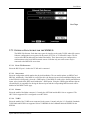
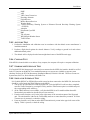
2.7.4 MISCELLANEOUS SETUP OPTIONS
1. Press the MISC smart key while still in the INSTL function.
2. Ensure the Misc Setup Options pages of the MX20 are configured with respect to the aircraft it is
being installed in. Modifications can be made using the line select keys.
See Step 3
See Step 4
See Step 5
30
Apollo MX20 Installation Manual
Installation
3. Obtain ICAO address of the aircraft from the FAA only if the UAT/ADS-B system is installed. The
ICAO address is a unique eight number code assigned to each aircraft. For U.S. registered aircraft, it
will be necessary to have a specific address code assigned. These address codes are presently issued
by:
Federal Aviation Administration
FAA Aircraft Registry
P.O. Box 25504
Oklahoma City, OK 73125
Tel: (405) 954-3116
Fax: (405) 954-3548
If the aircraft is registered in a country other than the United States, please contact the local aviation
authority of the country in which the aircraft is registered.
4. Enter in Flight ID. (Required if UAT/ADS-B system is installed.)
5. Enter Category Code. (Required if UAT/ADS-B system is installed.)
Category Code
Aircraft Weight
Small
< 15,500 lbs.
Medium
15,500 to 75,000 lbs.
Large
75,000 to 190,000 lbs.
Extra Large
190,000 to 300,000 lbs.
Heavy
> 300,000 lbs.
High Performance
> 5g acceleration and > 400 kts
6. Enter in Ownship Symbol (Single Engine, Twin, or Jet).
7. Set the Terrain Clearance Mode to Normal for all operations.
8. Demo Mode must be disabled for all aircraft installations.
9. Press Enter/Menu to confirm all settings.
10. After the 30-second waiting period, turn the MX20 power off to apply all configuration settings.
NOTE
MX20 power must be cycled before configuration changes will take affect.
After a configuration change, a message will appear on the screen telling you to wait 30 seconds
before turning off power. You may continue to make configuration changes without pausing;
however, do not turn off power to the MX20 until waiting 30 seconds after the last configuration/
setting change. The message will disappear when it is safe to cycle power.
Apollo MX20 Installation Manual
31
Installation
2.8 MX20 POST INSTALLATION CHECKOUT
Once the unit is installed, complete the checkout procedure to verify proper operation. Refer to the MX20
Multi-Function Display User’s Guide, 560-1026-xx, for operating instructions.
2.8.1 MOUNTING / WIRING CHECK
Verify that all cables are properly secured and shields are connected to the rear of the mounting frame. Check
the movement of the flight and engine controls to verify that there is no interference. Ensure wiring is
installed in accordance with AC 43.13-1B, Chapter 11.
2.8.2 SOFTWARE AND DATABASE TEST
1. Turn on power to the MX20.
2. Verify all self-tests pass on the main startup screen.
3. Verify the expiration on the NavData database.
4. Verify the Terrain and Geography databases are applicable to the area of intended flight (CONUS,
Alaska, etc.).
5. Press the MSG smart key and verify that “Unit configured for Special Terrain Mode” is NOT
displayed.
2.8.3 EXTERNAL DATA SOURCE TESTS
Verify that all external data sources are connected. See section 3.1.13 to check the compatibility of the
external devices for use with the MX20.
1. Turn on power to the MX20 and the external data sources. Activate the Installation Mode (see section
2.7).
2. Verify that the MX20 data ports are configured properly. See sections 2.5.1 and 2.5.2 for details on
the data port configuration. See section 2.7 for information on configuring the MX20 in Installation
Mode.
3. Recycle power to the MX20 to reinitialize it with any changes made in the Install function settings.
32
Apollo MX20 Installation Manual
Installation
4. Verify that the external data sources are properly configured to output the proper data to the MX20,
i.e., the Apollo GX should be configured to output Moving Map data. If the altitude data is supplied
from a GX model unit, it must have extended mode enabled.
Step 7-10
Step 12-15
Step 5
5. Check the System Info page on the MX20 to verify that the data is available to each port and that it is
being processed properly.
6. Verify ALT data flag is not displayed in the lower left portion of the MX20 display.
7. With external navigation source off, the POS and RTE data flags should be present.
NOTE
! The external navigation source may need to be properly configured prior to this step.
! Direct To sequence may need to be entered for external navigation source to output POS
and RTE.
! If an internal GPS exists, it can also provide a valid position to the MX20.
8. Turn the external navigation source power on. Verify that the navigation source acquires a position.
9. Create/activate a flight plan on the external navigation source.
10. Verify the RTE and POS data flags are not displayed.
11. Flight plan will be displayed on the MX20 on the FPL page.
12. Turn the traffic source power on. Verify the SKWY, TCAD, XPDR, or TRAF data flags are not
displayed.
13. With the Lightning sensor turned off, verify that the LT data flag is displayed.
14. Turn the Lightning sensor power on. Verify that the LT data flag is not displayed.
15. With the WSI InFlight sensor, if installed, turned off, verify that the Link data flag is displayed.
Apollo MX20 Installation Manual
33
Installation
16. Turn the WSI InFlight sensor on. Verify that the Link data flag is not displayed.
2.8.4 EMI/RFI TEST
This test validates that interference does not exist between the MX20 and other systems on the aircraft. Turn
off the power to all avionics devices.
2.8.4.1
TEST WITHOUT MX20
1. Start the aircraft engine(s) and switch to engine power, as appropriate.
2. Turn on power to the external GPS navigation source. Clear visibility to satellites is required.
3. Load a flight plan on the external GPS navigation source.
4. Test the function and/or observe for operation of each of the following if installed, or other
appropriate systems.
____ Transponder (if equipped)
____ NAV/VOR/ILS unit and tune to a local frequency (VOR/DME)
____ Any other navigation source
____ Radio Altimeter
____ DME
____ ADF
____ VHF Comm Transceiver
____ Encoding Altimeter
____ Flight Director
____ Marker Beacon Receiver
____ Weather Radar
____ Ground Proximity Warning System
____ Autopilot
____ Directional Gyro/HSI
____ RMI
____ WSI InFlight Weather Sensor. Visibility to the southern sky is required. The aircraft must
be far enough from buildings to avoid multipath effects. Note if the InFlight sensor causes
interference to other equipment. The MX20 must be turned on to see any effects on the
WSI InFlight sensor by other equipment.
____ Garmin GTX330 TIS-A Traffic Sensor. TIS-A is available only in areas with a Terminal
Approach Radar.
____ TAWS Sensor
5. Turn the power off to each of the avionics systems.
2.8.4.2 TEST WITH MX20
While performing the following tests, observe the MX20, external GPS navigation source (signal reception),
and the system under test for interference or abnormal operation.
1. Turn on power to the MX20.
2. Turn on the power to each avionics system. Observe for proper operation of the MX20 and the other
avionics systems.
____ Transponder (if equipped)
____ NAV/VOR/ILS unit and tune to a local frequency (VOR/DME)
____ Any other navigation source
____ Radio Altimeter
34
Apollo MX20 Installation Manual
Installation
____ DME
____ ADF
____ VHF Comm Transceiver
____ Encoding Altimeter
____ Flight Director
____ Marker Beacon Receiver
____ Weather Radar
____ Ground Proximity Warning System or Enhanced Ground Proximity Warning System
(EGPWS)
____ Autopilot
____ Directional Gyro/HSI
____ RMI
____ TIS-A Sensor
____ WSI InFlight Weather Sensor
____ TAWS Sensor
2.8.5 ALTITUDE TEST
1. Perform the installation and calibration tests in accordance with the altitude source manufacturer’s
installation manual.
2. Perform a flight check against the aircraft altimeter. Verify readings at ground level and at three
additional altitude points.
3. The altitude will be displayed on the bottom right-hand corner of the MFD terrain page.
2.8.6 COMPASS TEST
If the MX20 is located within seven inches of any compass, the compass will require a compass calibration.
2.8.7 STORMSCOPE INTERFACE TEST
If a Goodrich WX-500 Stormscope® sensor has been connected to the MX20, the interface should be verified
in the LT function on the MX20. Four standard Stormscope test screens are available to support system
checkout. Refer to the WX-500 Stormscope Installation Manual, P/N 009-11500-001. These test screens are
System Data, Self-Test, Noise Monitor, and Strike Test.
2.8.8 SKYWATCH INTERFACE TEST
If a Goodrich SKY497 or SKY899 Skywatch® sensor has been connected to the MX20 I/O, the interface
should be verified under the TRAF function on the MX20.
1. Turn power on to the MX20 I/O and Skywatch Unit. After the MX20 I/O self-tests have completed,
enter the Traffic Function by pressing the FN key until the TRAF menu option is available and press
the corresponding traffic smart key.
2. (If the TRAF function is not available, verify that the MX20 is an I/O model and that the traffic
function has been enabled as described in previous sections.)
3. From the traffic function, verify in the lower right corner of the screen that status of the Skywatch
unit. The unit should be either in the TAS Standby mode or no status should be presented. If a Data
Timeout error is presented, re-check the wiring.
4. From any function, verify that no amber SKYW annunciator is present in the upper left corner of the
display. If this is present, re-check the wiring.
Apollo MX20 Installation Manual
35
Installation
5. From the traffic function, or from the SKY1000 display if connected, command a Skywatch Self
Test. The status presented in the lower left of the display should change to a white ‘TAS Test’ and
clear after several moments.
6. From the Message function, verify that no error messages have been posted from the Skywatch
system.
2.8.9 RYAN TCAD INTERFACE TEST
If a Ryan TCAD 9900B or 9900BX sensor has been connected to the MX20 I/O, the interface should be
verified under the TRAF function on the MX20.
1. Turn power on to the MX20 I/O and TCAD unit. After the MX20 I/O self-tests have completed, enter
the Traffic Function by pressing the FN key until the TRAF menu option is available and press the
corresponding traffic smart key.
2. If the TRAF function is not available, verify that the MX20 is an I/O model and that the traffic
function has been enabled as described in previous sections.
3. Ensure that power is applied to the TCAD unit.
4. From the traffic function, verify that no amber TCAD Annunciator is present.
5. Perform additional checkout procedures in accordance to the TCAD installation manual.
2.8.10 RADAR CONFIGURATION & CHECKOUT PROCEDURES
The following steps are performed to verify the interface between the RADAR sensor and the MX20 I/O.
The radome should NOT be installed during these tests as visual verification of antenna movement is
required.
Note that the Antenna Receiver/Transmitter should be installed and calibrated in accordance to the
manufacturer’s specifications. This manual does not cover the installation or calibration of the actual ART
unit.
WARNING
Configuration procedures include steps that require the radar antenna to be powered on. Please
observe all safety precautions during these steps including: Do not perform in the vicinity of
refueling operations; Do not perform while personnel are in the vicinity (approximately 20 feet)
of the radar sweep area.
NOTE
See FAA AC20-68B “Recommended Radiation Safety Precautions For Airborne Weather Radar”
for safety precautions to be taken by personnel when operating airborne weather radar on the
ground.
2.8.10.1 ART 2000 CONFIGURATION AND CALIBRATION
2.8.10.1.1 Configuring the MX20
First configure the MX20 for the ART2000 option. Do this in the normal way by entering the install key
sequence (1, 4, 6) on the menu keys after boot-up is complete. Enable “RADAR” under the “FUNC” menuset, then select the “DATA” menu-set and select the “ART2000” choice. After selection, wait 30 seconds then
turn the power off and on again. Note that the MX20 is compatible with the ART2100 when the ART2100 is
programmed to emulate the ART2000.
36
Apollo MX20 Installation Manual
Installation
2.8.10.1.2 Calibration Procedures
Refer to the Bendix/King RDR 2000 Color Weather Radar System Installation Manual, Revision 4 or later.
Follow the instructions in "Stabilization calibration with Radar Indicator" or its equivalent.
Skip the description in the RDR 2000 manual on how to enter calibration mode. The MX20 allows a single
button push to enter calibration mode. The MX20 MUST be in Install mode to calibrate the radar head.
Follow the instructions below.
1.
2.
3.
4.
5.
6.
7.
8.
9.
Turn the MX20 on.
After boot-up is complete, key-in the install sequence 1, 4, 6, on the menu keys.
Press the FN key until one of the options is RADAR. If the RADAR option is not available, see the
section on "Configuring Radar".
Press the "smart key" corresponding to the RADAR option. You will now switch to the Radar page.
Press the STBY key to put the radar unit into standby mode. This may take up to twenty seconds.
Once the MX2O is in standby mode, one of the menu options will be "Test". Press the TEST key.
Once the MX20 is in Test mode, press the ENTER key to switch to the "Setup" page.
On the "Setup" page, press the key labeled CALB to enter calibration mode. This will take a couple
of seconds.
The MX20 will flash all faults briefly to indicate calibration mode has been entered. If this fails, turn
power off and try again.
At this point, follow directions in the RDR 2000 Installation Manual starting with "400 Hz Ref Gain" section.
Selection of calibration parameters is done by adjusting the gain setting according to the values in the RDR
2000 Installation Manual. On the MX20, the "smart keys" labeled "Gain" are used to adjust the gain setting
and select the parameter to be calibrated. Follow the RDR 2000 Installation Manual instructions for
calibrating the selected parameters.
2.8.10.2 RS-181A CONFIGURATION AND CALIBRATION
2.8.10.2.1 RS-181A Calibration
First configure the MX20 for the RS181 option. Do this in the normal way by entering the install key
sequence (1, 4, 6) on the menu keys after boot-up is complete. Enable “RADAR” under the “FUNC” menuset, then select the “DATA” menu-set and select the “RS181” choice. After selection, wait 30 seconds then
turn the power off and on again.
2.8.10.2.2 RS-181A calibration and Roll/Trim
1. Turn the MX20 on and wait until the startup page is completely drawn. When the green labels on the
smart keys (buttons at bottom) appear, it’s complete.
2. Press menu keys 1, 4, 6 to enable install mode. (buttons on right-hand side numbering from top to
bottom)
3. Next press the “FN” key until the “RADAR” label appears, then press that key. This will cause a switch
to the “RADAR” page.
4. Press the “STBY/ON” button (top right) on the RADAR page.
5. Wait until the unit has powered-up. 15 to 30 seconds.
6. Three choices should appear on the menu keys: ON, TEST, OFF. Select TEST.
Apollo MX20 Installation Manual
37
Installation
7. A test pattern should appear within a few seconds.
8. Now press the “MENU/ENTER” key (bottom right) to get to the R/T Calibration SETUP page.
9. To enter calibration mode, press the “CALB” menu key. The “CALB” label should turn green and the
text near the bottom of the display should read “Calibration Enabled.”
10. From here you may follow the manufacturer’s calibration instructions and procedure or set the roll/trim
parameter. Remember that the antenna is radiating during the setting of roll/trim.
11. To return to test mode and the test-pattern display, press the “MENU/ENTER” key. Once you return to
test mode, calibration mode is disabled.
12. So each time you return to test mode and the test pattern, and then return to the R/T Calibration SETUP
page (by pressing the “MENU/ENTER” key, you will need to press the “CALB” key again to enter
calibration mode.
2.8.10.2.3 Setting Roll/Trim
When setting roll trim, after returning to r/t calibration (setup) page, it is important to wait 30 seconds then
power-off. Do not attempt to re-enter calibration mode or use the unit without cycling the power.
2.8.10.3 GROUND BASED CHECKOUT PROCEDURES
2.8.10.3.1 Radar Test Mode Checkout
Turn power on to the MX20 I/O and radar antenna assembly. After the MX20 I/O self-tests are completed,
enter the Radar Function by pressing the FN key until the RADAR menu option is available. Then, press the
corresponding RADAR "smart key."
(If the Radar Function is not available, verify that the MX20 is an I/O model and that the radar function has
been enabled as described in previous sections).
The RADAR should remain in the off state with no scanning occurring when the Radar Function is entered
for the first time.
2.8.10.3.2 Test Pattern
Press the ON/STBY line item and allow approximately twenty seconds for the radar to power up. Verify at
this point that the RADAR powers up and performs the antenna clearance test. Once the unit is powered-up,
the radar will be in standby mode.
Press the TEST line item to place the unit in Test mode.
Verify that the test pattern is displayed. Press the range UP/DOWN keys if necessary until the test pattern can
be seen.
2.8.10.3.3 Tilt Test
Press the TILT line item and verify that the tilt can be adjusted from +15 degrees up, to –15 degrees down:
Pressing and holding the key will auto increment the value. Verify that both the RADAR antenna
mechanically follows the commands and that the display tilt indicator value on the MX20 I/O screen
corresponds to the actual angle of the antenna.
38
Apollo MX20 Installation Manual
Installation
2.8.10.3.4 Vertical Test - ART 2000 ONLY
Press the VERT line item and verify that the antenna scan changes from the horizontal profile to the vertical
profile.
2.8.10.3.5 Radar On Mode Checkout
WARNING
When in ON mode, the radar antenna will be radiating.
If the MX20 radar function is not in standby mode, place it in standby mode by pressing the STBY line item.
Once in standby, press the ON line item (same key as STBY). The unit is now in “WX” mode. Verify that
the mode can be changed to MAP mode by pressing the MAP line item. Now verify that the unit can be
placed in vertical profile by pressing the HORZ/VERT line item (ART 2000 ONLY). The display should
change to a vertical profile scan.
1. Press the Brg "smart keys" and verify that the bearing can be changed from 45 L to 45 R. ART
2000 ONLY.
2. Press the TILT/BRG line item to select the TILT on mode. ART 2000 ONLY
3. Press the Tilt "smart keys" and verify that the tilt angle can be changed from 15 DN to 15 UP.
The Radar Function should still be in MAP mode. If not in MAP mode, press the MAP line item. In map
mode the bottom line item will have a second option: GAIN. Press the GAIN line item. A bar-gauge should
appear in the bottom left of the display. Verify that the gain can be adjusted from minimum to maximum by
pressing the Gain "smart keys." At minimum, the green bar in the gauge will not be present. At maximum, the
green bar fills the entire gauge.
2.8.10.4 FINAL RADAR CHECKOUT
Ensure all ground checkout procedures are completed and verified prior to "open air" checkout.
With stabilization on, during takeoff or prolonged aircraft maneuvers, the displayed radar returns may not be
accurate. Point the aircraft radar sensor across the airport and paint buildings and terrain.
2.8.11 LANDMARK TAWS8000 AND KGP560 CHECKOUT PROCEDURE
2.8.11.1 KGP560 CONFIGURATION
The MX20 with I/O option and version 5.0 (or later) software is required in order to display terrain from the
KGP-560 EGPWS. External terrain caution and warning annunciator lamps are also required.
The figure below shows the connections between the MX20 display and the KGP560 EGPWS.
62-pin D-sub
Connector
ARINC 453/708 IN 1
A
B
21
42
30
10
A
B
KCPB OUTPUT
ARINC 429 OUT 0
A
B
18
17
47
66
A
B
RANGE IN
ARINC 429 IN 1
A
B
61
62
68
49
A
B
EGPWS ARINC 429 OUT
MX 20 Display
KGP560 EGPWS
To interface with the MX20, the KGP560 must be configured as follows:
- Category 4: Terrain Display ID = 4
Apollo MX20 Installation Manual
39
Installation
- Category 5: I/O Discrete ID = 1
- Category 9: Terrain Display Popup ID = 0
The remainder of the KGP560 configuration items is installation-specific and consequently not specified.
NOTE
The MX20 will automatically range to 10 nmi if a terrain pop-up occurs.
NOTE
With Terrain Display ID 4 the peaks data will be embedded in the terrain sweep. A
future version of the MX20 will support Terrain Display ID 6 and display peaks data
outside the terrain sweep area.
2.8.11.2 GOODRICH LANDMARK TAWS AND HONEYWELL KGP560 TAWS CHECKOUT
If a Goodrich Landmark TAWS or Honeywell KGP560 TAWS system has been connected to the MX20 I/O,
the interface should be verified under the TER (Terrain) function on the MX20.
1. Turn power on to the MX20 I/O and the TAWS system. After the MX20 I/O tests have completed, enter
the Terrain Function by pressing the FN key until the TER menu option is available and press the
corresponding terrain smart key.
2. If the TER function is not available, verify that the MX20 is an I/O model and that the terrain function
has been enabled as described in previous sections.
3. After the TAWS has completed its self-tests, verify that an amber TAWS data-fail annunciator is not
present on the left side of the screen. Other annunciators may be present.
4. From the TAWS control panel, execute a self-test. The MX20 display should present the TAWS8000
generated test pattern.
5. After the self-test has completed, verify that the MX20 range up and range down keys change the
corresponding range being presented by the TAWS.
2.8.12 GARMIN GTX330 CHECKOUT PROCEDURE
First, perform the Post-Installation Checkout Procedure in Section 3.3 of the GTX330D Transponder
Installation Manual. Once completed successfully, turn on the MX20. After the MX20 self-tests are
completed, enter the Traffic (TRAF) function by pressing the FN key until the TRAF menu option is
available. Then, press the corresponding TRAF “smart” key, followed by the Menu/Enter key. Press the
“Operate” Line Selection key. Verify that “TIS Standby” is displayed in the lower right corner. Press the
“Standby” Line Selection key. Verify that “TIS Operating” or “TIS Unavailable” are displayed in the lower
right corner of the display.
2.8.13 WSI INFLIGHT CHECKOUT PROCEDURE
The checkout procedure involves checking that the satellite signal is acquired and being tracked. Turn on the
power to the MX20 and WSI InFlight receiver. After the MX20 performs its self-tests, enter the FIS function
by pressing the FN key until the FIS menu option is available. Then, press the corresponding FIS “smart key”
followed by the Menu/Enter key, and finally the “Status” Line Selection key. The top three lines indicate
signal reception quality. Perform the Post-Installation Checkout Procedure as described in Section 4 of the
WSI InFlight AV-120/200 Installation Manual.
40
Apollo MX20 Installation Manual
Installation
Apollo MX20 Installation Manual
41
Installation
NOTES
42
Apollo MX20 Installation Manual
Specifications
3 SPECIFICATIONS
This section includes detailed electrical, physical, environmental, and performance specifications for the
MX20.
3.1 MX20 FEATURES
3.1.1
DISPLAY
6" Diagonal, Color AMLCD Display
640x480 Resolution (921,600 RGB Dots)
65,535 Simultaneous Colors
Direct Sunlight Readable
Auto/Manual Dimming
3.1.2 USER INTERFACE
Back-lit, high tactile buttons
Six general purpose "line select keys"
Four general purpose "smart keys"
Dedicated Function and Menu/Enter keys
Front Panel Data-Card Access
Open Software Architecture
Field-Upgradeable Code
3.1.3 EXPANSION/INTERNAL ARCHITECTURE
Open software architecture
Field-Upgradeable software
PC-104/PC-104L expansion bus
Four external high-speed serial I/O ports
Four general purpose input flags
3.1.4 POSITION SOURCE
Primary - External GPS or Loran via RS-232 serial input
Optional internal GPS
3.1.5 ELECTRICAL
Table 6 – Unit Power Loads
Unit
MX20
MX20 with heater (1)
MX20 I/O
MX20 I/O with heater (1)
14 VDC
Typical
Max
2.0 A
3.0 A
3.0 A
4.0 A
2.5 A
3.5 A
3.5 A
4.5 A
28 VDC
Typical
Max
1A
1.5 A
1.5 A
2.0 A
1.25 A
1.75 A
1.75 A
2.25 A
Notes:
Heater element turns on below approximately 30oC.
Note: Circuits should be protected in accordance with guidelines in AC 43.13-1B, chapter 11, section 2,
paragraph 429. Power inputs should be across a minimum of all four specified input pins.
Apollo MX20 Installation Manual
43
Specifications
3.1.6 AVIONICS OUTPUTS
Serial Ports ......................................................3 High Speed RS232
1 High Speed RS422
3.1.7 AVIONICS INPUTS
Serial Ports ......................................................3 High Speed RS232
1 High Speed RS422
Discrete Inputs.................................................4 General Purpose
3.1.8 AVIONICS OUTPUTS (I/O MODEL)
Serial Ports ......................................................2 ARINC 429 High/Low
Discrete Outputs..............................................3 General Purpose
3.1.9 AVIONICS INPUTS (I/O MODEL)
Serial Ports ......................................................2 ARINC 429 High/Low
2 ARINC 453/708 Radar
3.1.10 SERIAL INTERFACE DATA SOURCES
Position Source................................................Apollo GX50/55/60/65, Apollo CNX-series, or internal GPS
Apollo SL50/60
Trimble 2000, 2000 Approach, 2000 Approach Plus, 2101,
2101 I/O, 2101 I/O Plus
Garmin GNC 250 XL, GNC 430/530, and equivalent
Bendix/King KLN 90B TSO and equivalent
Northstar Avionics M3 GPS Approach
Nav Source ......................................................Apollo SL30, Apollo CNX-series
Altitude Source................................................Apollo SL70
Apollo CNX-series,
Apollo GX50/55/60/65 (with extended data enabled)
Trans-Cal SSD120-(XX)(x)-RS232-(XX)
ICARUS U3000
Sandia Aerospace Model SAE5-35
Traffic Source..................................................Apollo UAT
(only one traffic source may be connected
L-3 (Goodrich) SKY497 (MX20 I/O Model Only)
to the MX20)
L-3 (Goodrich) SKY899 (MX20 I/O Model Only)
Ryan TCAD 9900B (MX20 I/O Model Only)
Ryan TCAD 9900BX (MX20 I/O Model Only)
Garmin GTX330 (MX20 I/O Model Only)
Weather Source ...............................................Apollo UAT
Bendix/King RDR2000 Radar (MX20 I/O Model Only)
RDR2100 (MX20 I/O Model Only)
Allied Signal RS-181A (MX20 I/O Model Only)
L-3 (Goodrich) WX500
WSI InFlight (MX20 will communicate at 38,400 baud)
Terrain TAWS Source.....................................L-3 (Goodrich) Landmark TAWS 8000
Honeywell KGP-560 EGPWS
3.1.11 PHYSICAL SPECIFICATIONS
Height .............................................................5.00 inches (12.7 cm)
44
Apollo MX20 Installation Manual
Specifications
Width...............................................................6.25 inches (15.88 cm)
Depth...............................................................8.00 inches (20.3 cm)
Table 7 - Unit Weights
Unit
MX20 only, with GPS
MX20 only, without GPS
MX20 only, with I/O Option
MX20 mounting tray only
Weight
4.08 lb.
3.92 lb.
4.07 lb.
0.73 lb.
(1.85 kg)
(1.78 kg)
(1.85 kg)
(0.33 kg)
3.1.12 ENVIRONMENTAL SPECIFICATIONS
Operating Temperature ...................................-20°C to +55°C
Storage Temperature .......................................-55°C to +85°C
Temperature Variation ....................................2°C per minute
Humidity .........................................................95% at 50°C
Maximum altitude ...........................................35,000 ft
Cooling............................................................Not Required
3.1.13 TSO AUTHORIZATIONS
The MX20 meets the following TSO authorizations when connected to the following units:
JTSO
JTSO 2C63c
JTSO C110a
TSO
TSO C63c
TSO C110a
JTSO C113
JTSO C118
(TCAS)
TSO C113
TSO C118
(TCAS)
TSO C147
(TAS)
Manufacturer and Model
Bendix King ART2000
L-3 (Goodrich) WX 500 Stormscope
L-3 (Goodrich) NY-163 Stormscope Antenna
L-3 (Goodrich) NY-163 Stormscope Antenna
All Configurations
L-3 (Goodrich) NY-156 Antenna
L-3 (Goodrich) Skywatch HP SKY899A or
L-3 (Goodrich) Skywatch HP SKY899 (nonJTSO)
L-3 (Goodrich) Skywatch SKY497
(SW Version 1.6, or later)
L-3 (Goodrich) Skywatch HP SKY899
L-3 (Goodrich) NY-156 Antenna
L-3 (Goodrich) NY-164 Antenna
RYAN TCAD Model 9900B
RYAN TCAD Model 9900BX
RYAN Antenna set (top and bottom mount)
Apollo MX20 Installation Manual
Part Number
071-01519-0101
805-11500-001
805-10930-001 (White)
805-10930-001 (Black)
805-10003-001
805-11900-002
805-11900-001
805-10800-001
805-11900-001
805-10003-001
805-10800-001
70-2400
70-2420
70-2410
45
Specifications
3.1.14 INTERNAL GPS RECEIVER PERFORMANCE
Number of channels ........................................8
Frequency........................................................1575.42 MHz L1, C/A code
Sensitivity (acquisition) ..................................-135 dBm
Sensitivity (drop lock) ....................................-142 dBm
Dynamic range ................................................> 20 dB
Lat/Lon position accuracy...............................15 meters RMS typical
25 meters, SEP, without SA
100 meters 2DRMS with SA
Velocity...........................................................1000 knots maximum
Acceleration ....................................................4G maximum
TTFF (time to first fix) ...................................25 seconds typical with current almanac, position, time, and
ephemeris
55 seconds typical with current almanac, position, and time
Reacquisition...................................................2.5 seconds typical
Position update interval...................................1 second typical
Datum..............................................................WGS-84
46
Apollo MX20 Installation Manual
Specifications
3.2 REAR CONNECTOR PINOUTS
Table 8 - MX20 Rear Panel Connector Pinout (J1)
Pin #
1
2
3
4
5
6
7
8
9
10
11
12
13
14
15
16
17
I/O
I
I
I
I
O
O
I
O
O
I
I
I
I
I
O
Name
Power +
Power ground
Port 2 GND
Port 1 IN
Port 1 OUT
Port 3 OUT
Port 3 IN
Port 4 OUT +
NC
Port 4 OUT Port 4 IN +
Power ground
NC
Input Flag 1
Input Flag 3
Heater Power +
1 PPS OUT +
18
19
O
NC
1 PPS OUT -
20
21
22
23
24
25
I
I
O
I
O
I
Power ground
Port 2 IN
Port 2 OUT
Port 1 GND
Reserved (Power)
Port 3 GND
Port 2 RS-232 RxD
Port 2 RS-232 TxD
RS-232
NC In Aircraft Install
RS-232
26
27
28
29
30
31
32
33
34
35
36
37
I
I
I
I
I
I
I
-
Port 4 IN Reserved (Ground)
Reserved (Data)
Reserved (Clock)
NC
NC
NC
Input Flag 2
Input Flag 4
NC
External Power Switch
NC
Port 4 RS-422 RxD NC In Aircraft Install
NC In Aircraft Install
NC In Aircraft Install
Reserved
Reserved
Reserved
Discrete Input (Internally Pulled Up)
Discrete Input (Internally Pulled Up)
Reserved
External Power Switch (Gnd to Turn On)
Reserved
Apollo MX20 Installation Manual
Comment
Main Aircraft Power Input (+10 to +30 VDC)
Main Aircraft Power Ground
RS-232
RS-232
RS-232
RS-232
RS-232
RS-422
Reserved
RS-422
RS-422
Reserved
Discrete Input (Internally Pulled Up)
Discrete Input (Internally Pulled Up)
Auxiliary Heater Input (+10 to +30 VDC)
1 Pulse Per Second Output (RS422 Level). GPS timing is
referenced to the falling edge of +.
Reserved
1 Pulse Per Second Output (RS422 Level). GPS timing is
referenced to the rising edge of -.
47
Specifications
Table 9 - MX20 I/O Connector Pinout (J2)
Some features listed are not supported at this time
Pin
Name
I/O
Description
1
SYNCHRO_0_X
I
Reserved
2
SYNCHRO_0_Z
I
3
SYNCHRO_0/1_REF_LO
I
4
SYNCHRO_1_X
I
5
DISCRETE_OUT_0
O
Discrete Output number 0
6
DISCRETE_OUT_1
O
Discrete Output number 1
7
DISCRETE_OUT_2
O
Discrete Output number 2
Reserved
8
DISCRETE_IN_8
I
9
+12V
O
10
GND
I
11
SHIFT_REG_S/L
O
12
561_DATA_IN_B
I
13
429_IN_6B
I
14
429_IN_5A
I
15
429_IN_4A
I
16
429_IN_2A
I
17
429_OUT_0B
O
18
429_OUT_0A
O
19
453/708_IN_0B
I
ARINC 453/708 Input port 0B
Reserved
20
5VAC
I
21
453/708_IN_1A
I
22
SYNCHRO_2_REF_HI
I
23
SYNCHRO_0_Y
I
24
SYNCHRO_0/1_REF_HI
I
25
SYNCHRO_1_Y
I
26
SYNCHRO_1_Z
I
27
DISCRETE_IN_2
I
28
DISCRETE_IN_4
I
29
DISCRETE_IN_6
I
30
DISCRETE_IN_5
I
31
SHIFT_REG_DATA_OUT
I
32
SHIFT_REG_CLK
O
33
VREF_8V2_REARINT
I
34
561_DATA_IN_A
I
35
429_IN_6A
I
36
429_IN_5B
I
37
429_IN_4B
I
38
429_IN_2B
I
39
429_IN_3A
I
40
453/708_IN_0A
I
ARINC 453/708 Input port 0A
41
5VAC
I
Reserved
42
453/708_IN_1B
I
43
SYNCHRO_2_REF_LO
I
44
SYNCHRO_2_X
I
45
SYNCHRO_2_Y
I
46
SYNCHRO_2_Z
I
47
DISCRETE_IN_0
I
48
DISCRETE_IN_3
I
49
DISCRETE_IN_7
I
50
DISCRETE_IN_1
I
48
Apollo MX20 Installation Manual
Specifications
51
52
53
54
55
56
57
58
59
60
61
62
+28V
429_OUT_1A
429_OUT_1B
561_CLK_IN_B
561_CLK_IN_A
561_SYNC_IN_B
561_SYNC_IN_A
429_IN_0B
429_IN_0A
429_IN_3B
429_IN_1A
429_IN_1B
I
O
O
I
I
I
I
I
I
I
I
I
ARINC 429 Output port 1A
ARINC 429 Output port 1B
Reserved
ARINC 429 Input port 0B
ARINC 429 Input port 0A
Reserved
View from rear of unit
Apollo MX20 Installation Manual
49
Specifications
NOTES
50
Apollo MX20 Installation Manual
Troubleshooting
4 TROUBLESHOOTING
This section provides information to assist troubleshooting if problems occur after completing the
installation. Use Table 10 to assist in troubleshooting.
4.1 TROUBLESHOOTING GUIDE
Table 10 - Troubleshooting Guide
Problem
Cause
Solution
Unit does not power up – blank
screen.
1.
1.
2.
3.
4.
Improper wiring; circuit breaker
open.
Unit intensity turned down.
Unit is cold.
Data card improperly installed.
Unit fails during power-on self- Data card improperly installed.
test (POST).
INST function not shown in
install mode.
1.
2.
3.
Unit shows POS data flag.
Apollo MX20 Installation Manual
Improper key sequence entered.
Too many keys pressed in key
sequence.
Cycle through functions not
completed.
1.
Data port information not
correct.
2.
Antenna cables improperly
installed.
3.
Antenna is improperly installed.
4.
Waypoint not selected as the
current destination.
Ensure power is properly wired
to the MX20 and the circuit
breaker is closed.
2. Ensure that unit is not in manual
intensity control mode with the
intensity turned down.
3. If ambient temperature is below
10oC, allow unit to preheat for up
to 60 seconds.
4. Ensure that the data card is fully
inserted in the front bezel (It
should be flush with the ejector
button).
Ensure that the data card is fully
inserted in the front bezel (It should
be flush with the ejector button).
1. Ensure that the proper
installation key sequence is
carefully entered after the power
on self-test is complete.
2. Ensure that no other keys are
pressed prior to entering the
sequence.
3. Cycle through the available
functions by pressing the FN key
– INST function is on last
available function page.
1. Ensure that the data port
configuration is correct and
matches how the unit is wired for
the position source.
2. Ensure that the GPS antenna
cables are correctly installed on
the external GPS and the internal
GPS (if equipped).
3. Ensure that the GPS antenna is
correctly installed on top of
aircraft and aircraft is clear of
hangers, buildings and trees.
4. If a GX/SL series is used as the
position source, ensure that a
waypoint is selected as the
current destination (Nav Flagged
51
Troubleshooting
Table 10 - Troubleshooting Guide
Problem
Unit shows RTE data flag.
Unit shows ALT data flag.
Cause
5.
Position source not configured
on appropriate port.
6.
External GPS not properly
configured.
7.
RF interference.
External position source does not
have active route engaged.
1. Data port configuration
incorrect.
2.
1.
2.
Invalid altitude supplied to unit.
2.
1.
Data port configuration
incorrect.
1.
2.
SL30 is not powered up.
4.
SL30 information is not
displayed.
is not shown on primary nav
page).
5. If a GX/SL series is used as the
position source, ensure that it is
configured to output serial data
(MOV MAP) on the appropriate
port.
6. If other compatible external GPS
is used, ensure it is configured to
output serial position data on the
appropriate lines.
7. Ensure no RF interference at
1575 MHz from VHF Comm
antenna – add 1575 MHz notch
filter in Comm coax; Fix or
replace Comm; Disconnect the
ELT antenna coax to check.
Ensure that the external position
source has an active route engaged.
1. Ensure that the data port
configuration is correct and
matches how the unit is wired for
the serial altitude source.
2. Ensure that serial altitude
encoder is powered up and
functioning properly.
3. Ensure GX is turned on, shows a
valid altitude, and has acquired
position and valid waypoint.
4. Verify that GX has extended data
output enabled.
Serial altitude encoder not
powered up; not functioning
properly.
System is configured to use GX
unit as source for altitude data
and GX is not turned on.
System is configured to use GX
unit as source for altitude data
and GX not configured properly.
Terrain database incorrect.
1.
3.
Unit shows TER data flag.
Solution
2.
Unit shows DEMO data flag.
52
Ensure the unit has the
appropriate terrain database
loaded for the area of operation.
The terrain database is indicated
on the power-up and system
status pages of the MX20.
Ensure that valid altitude is being
supplied to the unit (an ALT data
flag should not be present).
Ensure that the data port
configuration is correct and
matches how the unit is wired for
the SL30.
Ensure the SL30 has power
applied.
Check wiring.
3.
3. Wiring connections are incorrect.
Demo mode enabled.
Ensure that demo mode is not
Apollo MX20 Installation Manual
Troubleshooting
Table 10 - Troubleshooting Guide
Problem
Cause
Solution
enabled in the install pages.
Unit posts message indicating
Incorrect terrain clearance mode
1. This is normal for special
‘Special’ terrain clearance mode improperly set.
‘Capstone’ support.
after power-up.
2. General aviation usage should
have the terrain mode set to
‘Normal’ in the install pages.
TCAD
1. Unit is not Traffic capable.
1. Ensure that the model MX20 is
2. Data port configuration
traffic capable.
incorrect.
2. Ensure that the data port
3. Traffic function not enabled.
configuration is correct and
4. TCAD unit not powered up; not
matches how the unit is wired for
functioning properly.
the serial interface.
5. Wiring connections are incorrect. 3. Ensure that the traffic function is
enabled.
4. Ensure that the TCAD unit has
power applied and is functional.
5. Verify serial wiring and pin
connections.
SKWY
1. Unit is not Traffic capable.
1. Ensure that the model MX20 is
2. Data port configuration
traffic capable.
incorrect.
2. Ensure that the data port
3. Traffic function not enabled.
configuration is correct and
4. Skywatch unit not powered up;
matches the model/unit that is
not functioning properly.
wired for the 429 interface.
5. Wiring connections are incorrect. 3. Ensure that the traffic function is
enabled.
4. Ensure that the Skywatch unit
has power applied and is
functional.
5. Verify 429 wiring and pin
connections.
RDR (Amber)
1. Unit is not radar capable.
1. Ensure that the model MX20 is
2. Data port configuration
radar capable.
incorrect.
2. Ensure that the data port
3. Radar function not enabled.
configuration is correct and the
4. Radar unit not powered up; not
model radar head is set correctly.
functioning properly.
3. Ensure that the radar function is
5. Wiring connects are incorrect.
enabled.
4. Ensure that the radar unit has
power applied and is functional.
5. Verify 453/708, 429 and discrete
wiring and pin connections.
Apollo MX20 Installation Manual
53
Troubleshooting
Table 10 - Troubleshooting Guide
Problem
Cause
Solution
LINK
1.
2.
3.
Ensure that the model MX20 is
WSI sensor capable.
Ensure that the data port
configuration is correct and the
WSI sensor is set correctly.
Ensure that the WSI sensor
function is enabled.
Ensure that the WSI sensor has
power applied and is functional.
5. Verify wiring and pin
connections.
1. If an internal fan is present, verify
that it is operational and that the
opening is clear of obstructions.
The fans should turn on when the
unit's internal temperature is
approximately 95-100ºF.
2. If an internal fan is not present,
one may be installed by the
factory. Contact factory.
4.
5.
Unit is not WSI sensor capable. 1.
Data port configuration incorrect.
WSI Inflight sensor function not 2.
enabled.
WSI Inflight sensor not powered
up; not functioning properly.
3.
Wiring connects are incorrect.
4.
MX20 runs hot.
Arrangement of avionics and
installation area does not provide
sufficient airflow.
XPDR
1.
2.
3.
4.
Split Screen function does not
appear.
Unit is not GTX330 capable.
Data port configured incorrectly.
Traffic function not enabled.
GTX330 not powered up or not
functioning properly.
5. Wiring connection are incorrect.
Split Screen function is not enabled.
1. Ensure that the model MX20 is
GTX330 capable.
2. Ensure that the data port
configuration is correct and the
GTX330 is set correctly.
3. Ensure that the GTX330 function
is enabled.
4. Ensure that the GTX330 has
power applied and is functional.
5. Verify wiring and pin
connections
Enable Split Screen function in
INSTL mode function page.
4.2 INTEGRATION TROUBLESHOOTING PROCEDURE
Use this procedure to check the integration of external data sources with the MX20.
1. Remove power to all external data sources and power on just the MX20.
2. Verify the correct power up sequence and access to the different functions of the MX20.
3. Verify that amber data flags are presented and own-ship is ‘X’d, indicating that external data sources
are not available. Allow the system to operate for several minutes to verify correct basic operation.
4. Apply power to each external data source one at a time. Verify that the corresponding amber data flag
extinguishes with each data source.
5. Verify that system operates correctly with the new data source by switching between different
functions and allowing the system to operate for several minutes. Repeat with the next data source.
54
Apollo MX20 Installation Manual
Troubleshooting
Note that the external GPS may need to acquire and set a destination waypoint before the ALT,
POS, and RTE flags clear.
6. If a given external data source causes a system error, verify compatibility and wiring. Re-verify port
assignments.
Apollo MX20 Installation Manual
55
Troubleshooting
4.3 CONTACTING THE FACTORY FOR ASSISTANCE
If the MX20 fails to operate despite troubleshooting efforts, contact the UPS Aviation Technologies
factory for assistance.
UPS Aviation Technologies, Inc.
2345 Turner Rd. SE
Salem, Oregon 97302
USA
Phone (503) 581-8101 or 1-800-525-6726
http://www.upsat.com
Be prepared to offer the following information about the installation:
• Installation configuration (accessories, antenna, ...)
• Model number, part number with mod levels, and serial number
• Software version
• Description of problem
• Efforts made to isolate the problem
56
Apollo MX20 Installation Manual
Periodic Maintenance
5 CONTINUED AIRWORTHINESS INSTRUCTIONS
The MX20 is designed to not require any regular maintenance except as included in this section:
5.1 EQUIPMENT CALIBRATION
The MX20 design requires no adjustments or calibration to be made.
5.2 CLEANING THE FRONT PANEL
The front bezel, keypad, and display can be cleaned with a soft cotton cloth dampened with clean
water. DO NOT use any chemical-cleaning agents. Care should be taken to avoid scratching the
surface of the display.
5.3 DISPLAY BACKLIGHT
The display backlight lamps are rated by the manufacturer as having a usable life of 10,000 hours.
This life may be more or less than the rated time depending on the operating conditions of the MX20.
Over time, the backlight lamps will dim and the display will not perform as well in direct sunlight
conditions. The user must determine by observation when the display brightness is not suitable for its
intended use. Contact UPS Aviation Technologies when the backlight lamps require service.
5.4 LITHIUM BATTERY REPLACEMENT
The internal keep-alive battery will require replacement after 5 years of service. The Li battery is only
included in MX units with internal GPS 430-0270-0xx. The effect of battery failure is a loss of the real
time clock in the GPS receiver. The unit will still work with loss of battery power; however, GPS
acquisition may take considerably longer time (20 minutes). There is no hazard associated with such a
failure.
To replace the battery, the MX20 must be removed from the aircraft and serviced by an appropriately
rated UPS AT service center. If the aircraft is to fly without the unit installed, placard the aircraft
accordingly.
Note: The battery is to be replaced ONLY with UPS AT part number 148-0052-00, or a UPS AT
approved equivalent.
CAUTION
The battery may explode if mistreated. Risk of fire, explosion, and burns. Do not
recharge, disassemble, heat above 100°C, or incinerate.
5.5 ALTITUDE ENCODER
In this VFR non-essential system, it is recommended that the altitude encoder be calibrated every 24
months. Refer to the manufacturer’s installation and calibration manual.
5.6 MANUALS
Incorporate operational test and troubleshooting guides into Aircraft Maintenance manuals. Update the
wiring diagram manual and equipment list as necessary. Add each component to the reliability
program as necessary.
Apollo MX20 Installation Manual
57
Periodic Maintenance
NOTES
58
Apollo MX20 Installation Manual
Environmental Qualifications
6 ENVIRONMENTAL QUALIFICATIONS
The MX20 has been tested to the following environmental categories per procedures defined in RTCA/DO160D.
Environmental Qualification Form
Part No:
TSO/JTSO
No:
430-0270-000 430-0270-500 430-0270-600
C110a
C110a
C110a
C113
C113
C113
C118
C147
430-0270-700
430-0270-800 430-0270-900
C63c/2C63c
C110a
C63c/2C63c
C110a
C113
C110a
C113
C118
C113
C118
C147
C118
C147
C147
Manufacturer:
UPS Aviation Technologies, Inc.
2345 Turner Road SE
Salem, Oregon 97302
Conditions
Section Description of Conducted Tests
Temperature and Altitude
4.0
Equipment tested to Category A1 and C1 with
Operating Temp
-20°C to +55°C
Short Time High Temperature
+ 70°C
Ground Survival Temperature
-55°C to +85°C
In-flight Loss of Cooling
4.5.4
No cooling required
Altitude
4.6.1
Equipment tested to 35,000 feet
Decompression
4.6.2
Equipment tested 8K to 35K in < 15 seconds
Overpressure
4.6.3
Equipment tested for overpressure
Temperature Variation
5.0
Equipment tested to Category C, 2°C/minute
Humidity
6.0
Equipment tested to Category A, standard humidity
environment
Operational Shocks and Crash Safety
7
Equipment tested to Category B5R for both operational and
crash safety shocks. (Equipment operated normally after the
crash safety shocks.)
Vibration
8.0
Standard vibration category S (curves M and B)
Robust Helicopter Vibration Category U (curves F and F1)
Explosion Proofness
9.0
Equipment identified as Category X, no test required
Waterproofness
10.0
Equipment identified as Category X, no test required
Fluids Susceptibility
11.0
Equipment identified as Category X, no test required
Sand and Dust
12.0
Equipment identified as Category X, no test required
Fungus Resistance
13.0
Equipment identified as Category X, no test required
Salt Spray
14.0
Equipment identified as Category X, no test required
Magnetic Effect
15.0
Equipment is Class Z, < 0.3 meters
Power Input
16.0
Equipment tested to Category B for 14 and 28 VDC
Voltage Spike
17.0
Equipment tested to Category A
Audio Frequency Conducted
18.0
Equipment tested to Category B
Susceptibility - Power Inputs
Induced Signal Susceptibility
19.0
Equipment tested to Category C, Z
Radio Frequency Susceptibility
20
Equipment tested to Category V (Conducted)
(Radiated and Conducted)
Equipment tested to Category V (Radiated)
Emission of Radio Frequency
21
Equipment tested to Category M
Energy
Lightning Induced Transient
22.0
Equipment tested to Category A3 and B2
Susceptibility
Lightning Direct Effects
23.0
Equipment identified as Category X, no test required
Icing
24.0
Equipment identified as Category X, no test required
Electrostatic Discharge
25.0
Equipment tested to Category A
Remarks:
Apollo MX20 Installation Manual
59
Environmental Qualifications
NOTES
60
Apollo MX20 Installation Manual
Environmental Qualifications
APPENDIX A – I/O SPECIFICATIONS
This appendix includes the RS-232 serial port interface specifications.
6.1 MOVING MAP INPUT
The format of the moving map data output is as follows. Definitions of the input data is included in
Table 11 and Table 13. A sample output message is included in Figure 21.
Baud rate: ............................................... 9600
Data bits: ................................................ 8
Stop bits: ................................................ 1
Parity: ..................................................... none
Output rate: ............................................ approx. 1 seconds
Message length: ..................................... variable, approx. 83 to 484 characters
The serial output messages are in the following format.
<STX><id><data><it><id><data><it>...<id><data><it><ETX>
<STX> ................................................... ASCII “start of text” character (1 byte, 02h)
<id> ........................................................ item designator (1 byte, from following table)
<data> .................................................... item data (format listed in following table)
<it> ........................................................ item terminator (1 byte, 0Dh)
<ETX> ................................................... ASCII “end of text” character (1 byte, 03h)
Table 11 - Moving Map ASCII Navigation Data
ID
A
Data Format
sddmmhh
B
sdddmmhh
10
C
D
E
G
ddd
ddd
ddddd
sdddd
3
3
5
5
I
dddd
4
K
ddd[dd]
L
dddd
4
Q
sddd
4
Apollo MX20 Installation Manual
Length
9
3 to 5
Description
Present latitude
s =sign: N for north, S for south
dd = degrees
mm = minutes
hh = hundredths of minutes
Present longitude
s = sign: E for east, W for west
ddd = degrees
mm = minutes
hh = hundredths of minutes
Track (magnetic): ddd = degrees
Ground speed: ddd = knots
Distance to active waypoint: ddddd = nm x 10
Cross track error:
s = sign: R for right, L for left of course
dddd = distance off course, hundredths of nm
Desired track (magnetic):
dddd = degrees x 10
Active waypoint identifier:
ddd[dd] = ASCII waypoint identifier
Bearing to active waypoint (magnetic):
dddd = degrees x 10
Magnetic variation:
61
Environmental Qualifications
Table 11 - Moving Map ASCII Navigation Data
ID
Data Format
T
---A-----
Length
9
Description
s = sign: E for east, W for west
ddd = degrees x 10
Warnings: The 4th character will be an “A” when
the navigation data is flagged, otherwise, all
characters will be dashed. All other navigation data
will be dashed when it is flagged.
6.2 BINARY NEAREST LIST DATA (WHEN EXTENDED DATA IS
ENABLED ONLY)
The nearest waypoints lists are sent one waypoint per data transmission set. The lists are sent in
the following order:
• LFAC
• VOR
• NDB
• INT
• User
There is a maximum of twenty waypoints per type. The waypoints are a maximum of 600 nm
from the current position. The waypoints are order by distance from current position nearest to
farthest. The maximum time to send all lists is 100 second. Each list is updated just prior to the
first waypoint in the list being sent. If a list is empty a shorter record will be sent with the List Item
Number set to 0xFF.
Table 12 - Nearest Waypoint List Data
Byte
1
2
Format
Z
sddddddd
3
t
4
Cr
Description
‘Z’ Item Designator
List Item Number: Packed, unsigned binary values
s
= 1 End of list, 0 all other
ddddddd = 1 – 20 list waypoint index
sddddddd = 0xFF List Type is EMPTY (BYTE 4 terminate Item)
Waypoint Type:
t = {a (airport) || v (VOR) || n (NDB) || i (INT) || u (USER)}
‘\r’ Item Terminator <0x0d> (ONLY IF BYTE 3 = OxFF)
4-8
ddddd
ASCII Waypoint Identifier
9
10
11
sddddddd
xxmmmmmm
xhhhhhhh
12
13
14
15
sxxxxxxx
dddddddd
xxmmmmmm
xhhhhhhh
Latitude of waypoint. Packed, unsigned binary values for degrees, minutes
and hundredths of minutes.
s
= 0 North latitude, 1 South latitude
x
= undefined
ddddddd = Latitude degrees
mmmmmm = Latitude minutes
hhhhhhh
= Latitude hundredths of minutes
Longitude of waypoint. Packed, unsigned binary values for degrees, minutes
and hundredths of minutes.
s
= 0 East longitude, 1 West longitude
62
Apollo MX20 Installation Manual
Environmental Qualifications
Table 12 - Nearest Waypoint List Data
Byte
Format
16
Cr
Description
x
= undefined
ddddddd = Longitude degrees
mmmmmm = Longitude minutes
hhhhhhh
= Longitude hundredths of minutes
‘\r’ Item Terminator <0x0d>
Table 13 - Moving Map Binary Route Data
Byte
1
2-3
4
Data Format
w
dd
xiannnnn
5-9
10
11
12
ddddd
sddddddd
xxmmmmmm
xhhhhhhh
13
14
15
16
sxxxxxxx
sddddddd
xxmmmmmm
xhhhhhhh
17
18
nnnnnnnn
nnnnnnnn
19
<CR>
Apollo MX20 Installation Manual
Description
Item designator
Current waypoint number in ASCII (01h to 20h)
Sequence number
x = undefined
i = 1 if last waypoint
a = 1 if active waypoint
nnnnn = unsigned binary waypoint number
ASCII waypoint identifier
Waypoint latitude - packed, unsigned binary
s = sign: 0 for north, 1 for south
ddddddd = degrees
mmmmmm = minutes
hhhhhhh = hundredths of minutes
x = undefined
Waypoint longitude
s = sign: 0 for east, 1 for west
ddddddd = degrees
mmmmmm = minutes
hhhhhhh = hundredths of minutes
x = undefined
Magnetic variation at waypoint
LS byte (msbit...lsbit)
MS byte (msbit...lsbit)
Two’s complement binary in sixteenths of degrees, easterly variation
is positive.
ASCII carriage return (0Dh)
63
Environmental Qualifications
6.3 FLIGHT PLAN WAYPOINT TYPES (WHEN EXTENDED DATA IS
ENABLED ONLY)
The following data is only transmitted when preceded by flight plan data. There is one character per
flight plan waypoint transmitted.
Table 14 - Flight Plan Waypoint Type
Id
t
Item
Format
nnn…
Len
Description
1-21
n = { a (airport) ||
v (VOR) ||
n (NDB) ||
i (intersection) ||
u (user) ||
p (parallel track) ||
d (direct to) ||
F (FAF) ||
I (IAF) ||
H (MAHP) ||
A (IFAF) ||
P (undefined approach waypoint type) }
Example Moving Map Data Output (Extended Data Disabled)
AN 34 1570
34°15.70’ latitude
BW 118 4390
118°43.90’ longitude
C306
306° track angle
D210
210 knots
E02682
268.2nm to waypoint
GR0006
0.6nm right of course
I3059
305.9° desired track
KSFO
SFO waypoint ident
L3058
305.8° bearing to waypoint
QE140
14.0° east magnetic variation
T--------No alarms, data not flagged
<binary data>
From Table 9
Figure 21 - Moving Map Data Output (Extended Data Disabled)
64
Apollo MX20 Installation Manual
Environmental Qualifications
Example Moving Map Data Output (Extended Data Enabled)
AN 34 1570
34°15.70’ latitude
BW 118 4390
118°43.90’ longitude
C306
306° track angle
D210
210 knots
E02682
268.2nm to waypoint
GR0006
0.6nm right of course
I3059
305.9° desired track
KSFO
SFO waypoint ident
L3058
305.8° bearing to waypoint
QE140
14.0° east magnetic variation
T--------No alarms, data not flagged
<binary data>
From Table 7
a—O--F
Approach Enabled Off, Active Off, Message On, Parallel Track
Off, Hold Off, and From/To is FROM
cvR001
CDI Valid, Needle Right, Deflection 001°
vC000
VDI Valid, Needle Centered, Deflection is 000°
<binary data>
From Table 13
tda
Flight Plan Waypoint Type data, direct-to, airport type
Figure 22 - Moving Map Data Output (Extended Data Enabled)
Apollo MX20 Installation Manual
65
Environmental Qualifications
6.4 ALTITUDE ENCODER/CONVERTER INPUT
The format of the altitude input is as follows. Definition of the input message is included in Table 15.
Several sample messages are illustrated in Figure 23Error! Reference source not found..
Baud rate: ...............................................1200
Data bits: ................................................8
Stop bits: ................................................1
Parity: .....................................................none
Expected input rate: ...............................approx. 1 second
Message length: ......................................17 characters
Table 15 - Altitude Input Data
Byte
1
2
3
4
5
6-10
11
12
13-14
15-16
17
Data Format
“#”
“A”
“L”
““
“+” or “-”
ddddd
“T”
“+” or “-”
dd
dd
<CR>
Description
ASCII “#” (023h)
ASCII “A” (041h)
ASCII “L” (04Ch)
ASCII space (020h)
Altitude sign: ASCII “+” or “-” (02Bh or 02Dh)
Altitude in feet, right justified with leading zeros
ASCII “T” (054h)
Temperature sign: ASCII “+” or “-” (02Bh or 02Dh)
Internal altimeter temperature
Checksum of bytes 1 through 14, computed in hex, output in
ASCII format (i.e., “FA” hex)
ASCII carriage return (0Dh)
The altitude input can decode several status or error codes. These codes would be in place of the
altitude data in characters 5 - 10 as follows.
“-09980”..................................................Heater not ready: expected during encoder warm-up or if
there is a loss of signal from the encoder.
“-09981”..................................................Possible hardware problem: expected from encoder
indicating a temperature greater than 55°C or if data is
invalid.
“-09982”..................................................Altitude out of range: expected from the encoder
indicating that the altitude is outside specified range of
the encoder.
66
Apollo MX20 Installation Manual
Environmental Qualifications
Figure 23 - Altitude Data Input
6.5 STORMSCOPE INPUTS
The WX-500 is the only stormscope that the MX20 MFD interfaces with. It can be connected to RS422 or RS-232.
RS-232
Connection
Cable
Voltage
Baud Rate
Load Impedance
RS-422
Connection
Cable
Voltage
Baud Rate
Load Impedance
TX
J3-20
RX
J3-8
RS-232_GND
J2-5
Twisted shielded triad 24 AWG wire
Logic 0 (space) Min: +5V, Max: +15V
Logic 1 (mark) Min: -15V, Max: -5V
9600
3KΩ Min.
TX+
J3-25, TX- J3-13
RX+
J3-24, RX- J3-12
GND
CASE_GND
Twisted shielded pair 22 AWG
Logic 0 (space) Min (A-B): +2V, Max (A-B): +6V
Logic 1 (mark) Min (A-B): -6V, Max (A-B): -2V
9600
3KΩ Min.
Apollo MX20 Installation Manual
67
Environmental Qualifications
NOTES
68
Apollo MX20 Installation Manual