1
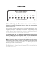
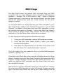
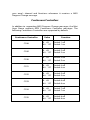
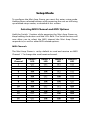
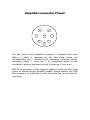
Mini Amp Gizmo
User’s Manual
RJM Music Technology, Inc.
Mini Amp Gizmo
User’s Manual
Version 1.1
March 15, 2012
RJM Music Technology, Inc.
2525 Pioneer Ave #1
Vista, CA 92081
E-mail: [email protected]
Web: www.rjmmusic.com
Copyright © 2009-2012 RJM Music Technology, Inc.
All Rights Reserved.
Amp Gizmo, Effect Gizmo, Mini Amp Gizmo, MasterMind, RG-16 and
the RJM logo are trademarks of RJM Music Technology, Inc.
Table of Contents
INTRODUCTION
6 FRONT PANEL
7 BACK PANEL
8 MIDI USAGE
10 Continuous Controllers
11 Bank Selection
12 Backing Up Your Settings: SysEx Dump
12 CONTROLLING MULTIPLE DEVICES
14 SETUP MODE
15 Selecting MIDI Channel and MIDI Options
15 MIDI Channels
15 Continuous Controller Ranges
16 GCX Compatibility Mode
16 Bank Select Enable
16 Saving MIDI Channel and Options
17 Invert Mode
17 Momentary Mode
17 Group Mode
18 Quick Setup Buttons
18 TROUBLESHOOTING
21 SPECIFICATIONS
22 AMPLIFIER CONNECTOR PINOUT
23 v
Introduction
Thank you for purchasing a Mini Amp Gizmo. This product is
designed to connect your amplifier, effects devices or other
electronic equipment to other MIDI-enabled equipment. The Mini
Amp Gizmo can control any device that uses short-to-ground
switching. This means that virtually any function that is controlled by
a footswitch can be MIDI controlled using the Mini Amp Gizmo. A
wide variety of interface cables are available, from our standard ¼”
adapter cable to custom cables for a wide variety of amps. With these
interface cables, the Mini Amp Gizmo can control most any amplifier
out there – more than any other switcher on the market – and we are
always developing new cables for other amplifiers and equipment.
Front Panel
Mini Amp Gizmo
MIDI Amplifier Controller
1
2
3
4
5
6
7
8
Write
RJM Music Technology, Inc.
Buttons 1 through 8 - These buttons turn function switches 1
through 8 on and off. The button lights up when the corresponding
function switch is on.
These function switches will control all footswitchable features of an
amplifier connected to the Mini Amp Gizmo. These features may
include channel, boost, effects loop or others – whichever features
are normally controlled using the amp’s footswitch.
The interface cable you use determines which button controls which
function. Please consult the instruction sheet that was included with
your cable to find the button to function mapping for your amp.
Write – When held down for 3 seconds, this button saves the current
switch state to non-volatile memory. This function is not active until
a Program Change message is received at the MIDI In jack. See the
MIDI Usage section for more details.
The Write button is always lit up with a green LED to indicate that the
Mini Amp Gizmo is on.
Back Panel
To Amplifier
MIDI Thru/Out
MIDI In
Power In/Out
9V AC/DC
RJM Music Technology, Inc.
www.rjmmusic.com
To Amplifier – Connect your custom amplifier interface cable here.
Use the cable end that has a yellow label reading “Rack Gizmo / Amp
Gizmo.” The other end of the cable plugs into your amp’s footswitch
jack. Before connecting, make sure that you have the cable that’s
made specifically for your amp, or the ¼” adapter cable if your amp
has ¼” footswitch jack(s). Cables are available for a variety of
amplifiers. Check our website for a list of currently available cables.
MIDI Thru/Out – All of the MIDI commands that are received at the
MIDI In jack are sent out through this jack. This jack also doubles as a
MIDI output when transferring SysEx data over MIDI. See the MIDI
Usage section for more details.
MIDI In – Jack for incoming MIDI commands. Connect your MIDI foot
controller here. The Mini Amp Gizmo will phantom power a
compatible MIDI controller if you use a 7-pin MIDI cable. The AC
adapter provided with the Mini Amp Gizmo can phantom power
many MIDI controllers provided that they can run on a 9V DC supply
and draw 250mA or less. Moving to a higher capacity power supply
will allow you to phantom power MIDI controllers with higher
current requirements – just add the current requirement of the
device with the Mini Amp Gizmo’s requirement (250mA) and make
sure your adapter can supply at least that amount of current.
Power – This unit requires power supply in the range of 9 to 12 volts,
AC or DC. The plug should be a 5.5mm/2.1mm barrel connector,
similar to those used in most effects pedals. The Mini Amp Gizmo
requires a minimum of 250mA of current.
MIDI Usage
The Mini Amp Gizmo can receive MIDI messages from any MIDI
controller. You can store different switch settings for MIDI program
numbers 1 through 128 in MIDI banks 0 and 1. When a Program
Change message is received on the correct channel, the Mini Amp
Gizmo will automatically recall the saved settings for the given
program number.
To set up for MIDI use, simply connect your MIDI controller to your
Mini Amp Gizmo’s MIDI In jack. The Mini Amp Gizmo is set for MIDI
Channel 1 by default. Either make sure your MIDI controller is set up
to transmit commands on Channel 1, or use the Mini Amp Gizmo’s
setup mode to change which MIDI channel the Mini Amp Gizmo
responds to. See the Setup Mode section for more details.
To save a program setting, perform the following steps:
1.
Using your MIDI controller, select a MIDI program number.
2.
Using the Mini Amp Gizmo buttons, select your amp’s
channel and functions.
3.
Hold down the Write button on the Mini Amp Gizmo until
the LEDs flash. This should take about 3 seconds.
That’s all it takes. You can repeat this for any or all of MIDI program
numbers 1 though 128.
If the lights don’t flash after a few seconds of holding down the Write
button, it means that your Mini Amp Gizmo did not receive the MIDI
Program Change message. Check your MIDI cable connection, and
make sure that the MIDI controller and Mini Amp Gizmo are set to
the same MIDI channel.
Now that your settings have been saved, you can recall your settings
by using your MIDI controller to send a Program Change message
again. The Mini Amp Gizmo will call up your saved settings and set
your amp’s channel and functions whenever it receives a MIDI
Program Change message.
Continuous Controllers
In addition to supporting MIDI Program Change messages, the Mini
Amp Gizmo supports MIDI Continuous Controller messages. The
following Continuous Controllers are supported by default:
Continuous Controller
Value
Function
CC88
0…63
64…127
Switch 1 off
Switch 1 on
CC89
0…63
64…127
Switch 2 off
Switch 2 on
CC90
0…63
64…127
Switch 3 off
Switch 3 on
CC91
0…63
64…127
Switch 4 off
Switch 4 on
CC92
0…63
64…127
Switch 5 off
Switch 5 on
CC93
0…63
64…127
Switch 6 off
Switch 6 on
CC94
0…63
64…127
Switch 7 off
Switch 7 on
CC95
0…63
64…127
Switch 8 off
Switch 8 on
*Setup Mode can be used to change which Continuous Controller
messages the Mini Amp Gizmo responds to. Please refer to the Setup
Mode section for more details.
Please note that settings such as Momentary Mode and Group Mode
are in effect when processing Continuous Controller messages.
Bank Selection
The Mini Amp Gizmo can store programs in MIDI banks 0 and 1, for a
total of 256 programs. Continuous Controller #0 (Bank MSB) is used
to select the current MIDI bank. Bank numbers above bank 1 are
ignored.
By default, bank selection is disabled. You can enable bank selection
using Setup Mode (see Setup Mode section).
Backing Up Your Settings: SysEx Dump
A SysEx (System Exclusive) data dump will send the current Mini Amp
Gizmo system configuration out through the MIDI Thru/Out port.
You can then save this data to your computer, or copy the settings
directly to another Mini Amp Gizmo.
Hold down the Switch 5 button while powering up the Mini Amp
Gizmo, and the Mini Amp Gizmo will immediately send the SysEx
Dump. It only takes a couple of seconds to complete.
If you wish to copy settings from one Mini Amp Gizmo to another,
connect the MIDI Thru/Out of the transmitting unit to the MIDI Input
of the receiving unit, then power up the transmitting unit while
holding down the Switch 5 button. (Note that the receiving Mini
Amp Gizmo must be powered on and not in setup mode.) The
receiving unit will display a progress bar graph on the LEDs. The
transfer goes very quickly, taking only a couple of seconds. In the
case of an error, the receiving unit will flash all LEDs 5 times.
Once the transfer completes, the receiving unit will reset, then return
to normal operating mode. The receiving unit now has an exact copy
of the transmitting unit’s settings.
Controlling Multiple Devices
The Mini Amp Gizmo features a single switching jack, making it best
suited to controlling a single amp. However, if you need to control
multiple amps or effects processors and they have ¼” footswitch
jacks, you can use our BOB-8 product. BOB-8 stands for BreakOut Box,
8 outputs. It connects to the Mini Amp Gizmo and provides eight
electrically isolated ¼” jacks. These jacks can safely be connected to
up to eight separate devices with no danger of electrical problems.
Setup Mode
To configure the Mini Amp Gizmo, you must first enter setup mode.
Holding down selected buttons while powering the unit on will bring
up selected setup modes, as detailed in this section.
Selecting MIDI Channel and MIDI Options
Hold the Switch 1 button while powering the Mini Amp Gizmo on.
Keep holding the button until the LEDs flash. The Switch buttons will
now allow you to select the MIDI channel the Mini Amp Gizmo
responds to, as well as other MIDI-related options:
MIDI Channels
The Mini Amp Gizmo is set by default to send and receive on MIDI
Channel 1. To change the send/receive channel:
MIDI
Channel
1
2
3
4
5
6
7
8
9
10
11
12
13
14
15
16
Switch 1
LED
OFF
ON
OFF
ON
OFF
ON
OFF
ON
OFF
ON
OFF
ON
OFF
ON
OFF
ON
Switch 2
LED
OFF
OFF
ON
ON
OFF
OFF
ON
ON
OFF
OFF
ON
ON
OFF
OFF
ON
ON
Switch 3
LED
OFF
OFF
OFF
OFF
ON
ON
ON
ON
OFF
OFF
OFF
OFF
ON
ON
ON
ON
Switch 4
LED
OFF
OFF
OFF
OFF
OFF
OFF
OFF
OFF
ON
ON
ON
ON
ON
ON
ON
ON
You can also set a few other MIDI-related options using the other
Switch buttons:
Continuous Controller Ranges
The Switch 5 and 6 buttons control the Continuous Controller range
for all switches:
CC Range
80…87
88…95 (default)
64…71
56…63
GCX
Number
1
2
3
4
Switch 5
LED
OFF
ON
OFF
ON
Switch 6
LED
OFF
OFF
ON
ON
GCX Compatibility Mode
Switch 7 turns on GCX compatibility mode. This makes the switches
respond to MIDI commands like the GCX switcher, manufactured by
Voodoo Lab. In GCX compatibility mode, the switches respond only
to Continuous Controller messages on MIDI channel 16, regardless of
the MIDI channel setting. The GCX number is set by Switches 5 and 6
(see above).
Bank Select Enable
Switch 8 controls whether or not the Mini Amp Gizmo will allow MIDI
bank selection. When Switch 8 is off, the Mini Amp Gizmo will ignore
MIDI bank select messages. When Switch 8 is on, the Mini Amp
Gizmo will respond to Bank Select messages as described in the Bank
Selection section.
Saving MIDI Channel and Options
Once you’ve set the MIDI channel and options, press the Write
button. The Mini Amp Gizmo is now in normal operational mode.
Invert Mode
Some amplifiers may have inverted polarity on some functions. This
can cause the Mini Amp Gizmo to display a function as off when the
function is actually on, and as on when the function is actually off. To
correct this, you must first switch the Mini Amp Gizmo to invert
mode.
Hold down the Switch 2 button while powering up the Mini Amp
Gizmo. Keep holding the button until the LEDs flash. You are now in
invert mode.
While in invert mode, use the front panel buttons to light the LED of
any function that is inverted. Make certain no other LED is lit.
Once you’ve selected the inverted function’s associated button(s),
press the Write button. The Mini Amp Gizmo is now in normal
operational mode, and the inverted functions should operate
correctly.
Momentary Mode
Some devices require momentary-type switching, rather than the
more common latching-type switches. (A momentary switch
changes OFF/ON state by closing its contacts for a short time and
then re-opening them. In momentary mode, the Mini Amp Gizmo
switches will close for 100 milliseconds before opening again.)
To enter momentary mode, hold down the Switch 3 button while
powering up the Mini Amp Gizmo. Keep holding the button until the
LEDs flash. Use the front panel buttons to light the LED of any
function that needs to be momentary. Make certain that no other
LED is lit.
Once you’ve selected the buttons for the momentary functions, press
the Write button. The Mini Amp Gizmo is now in normal operational
mode and the momentary functions should operate correctly.
Group Mode
The group mode feature allows you define a group of buttons where
pressing one button of the group turns that button on and turns all
other buttons in the group off. This is typically used for switches that
control which channel is selected on an amplifier. This prevents the
Mini Amp Gizmo from trying to activate more than one amp channel
at a time.
To enter group mode, hold down the Switch 4 button while
powering up the Mini Amp Gizmo. Keep holding the button until the
LEDs flash.
Use the front panel buttons to light the LED of any function that
should be in the group. Make sure that no other LEDs are lit.
Once you’ve selected the functions that need to be grouped, press
the Write button. The Mini Amp Gizmo is now in normal operational
mode and the grouped buttons will now only allow one button to be
selected at a time.
Quick Setup Buttons
Quick Setup buttons are provided to quickly set up the Mini Amp
Gizmo for common configurations. Which configuration you use
depends on the number of channels your amplifier has, and whether
the amplifier uses momentary switching or not.
To use this feature, hold down the Switch 8 button while powering
up the Mini Amp Gizmo. Keep holding the button until the LEDs all
turn on and stay on.
Next, press one of the following buttons. Based on the button
pressed, the Mini Amp Gizmo will configure the switches as follows:
Switch 1: No switches momentary or grouped. (Default setting)
Switch 2: First two switches grouped, no switches momentary. (Most
2 channel amps)
Switch 3: First three switches grouped, no switches momentary.
(Most 3 channel amps)
Switch 4: First four switches grouped, no switches momentary. (Most
4 channel amps)
Switch 5: All switches momentary, none grouped. (Rivera M and S
amps)
Switch 6: First two switches grouped and momentary.
Switch 7: First three switches grouped and momentary. (Bogner
Ecstasy, EVH 5150III)
Switch 8: First four switches grouped and momentary. (Marshall
Mode 4)
Once the button has been pressed and the LEDs have flashed, the
Mini Amp Gizmo will go directly to normal operating mode.
Troubleshooting
Problem: The LEDs don’t flash when you hold down the Write
Button.
Solution: The Mini Amp Gizmo did not receive a MIDI Program
Change message. First, verify that you have a valid MIDI connection.
The MIDI output of your MIDI controller should be connected to the
MIDI input of the Mini Amp Gizmo by a MIDI cable that’s known to be
working correctly. The next most likely cause is that the Mini Amp
Gizmo is set to a different MIDI channel than your MIDI controller.
Check both devices to insure that they’re set to the same channel. On
the Mini Amp Gizmo, the MIDI channel is set to 1 by default and can
be changed in Setup Mode.
Problem: I’m trying to control my amplifier, and it’s not working or
behaving erratically.
Solution: This can happen when using the wrong amplifier interface
cable, or if the Mini Amp Gizmo is not configured correctly for your
amp. Check the instruction sheet that came with your amplifier
interface cable, or check the Setup Mode section for more
information on how to configure. You can also check contact us at
RJM Music for assistance. We’d be happy to help you out.
Specifications
Dimensions
Weight
Power
Phantom
Power
Memory
Quarter-rack enclosure
4 (W) x 1.5 (H) x 4 (D) inches
10.2 (W) x 3.8 (H) x 10.2 (D) cm
10.3 ounces
300 grams
9 to 12 Volts, AC or DC @ 250mA
5.5mm OD, 2.1mm ID x 9.5mm barrel
connector
Provided over pins 6 and 7 of the MIDI In
jack. Phantom power voltage is the same as
the power provided at the Power jack.
256 programs, arranged in 2 banks of 128
Memory is non-volatile and requires no
backup battery
Amplifier Connector Pinout
7
3
6
1
8
5
4
2
The Mini Amp Gizmo amplifier connector is a female DIN-8 jack.
When a switch is activated on the Mini Amp Gizmo, the
corresponding pin is shorted to the connector’s ground (shield).
Activating Switch 1 shorts pin 1 (as numbered above) to the
connector’s ground. Activating Switch 2 shorts pin 2, and so on.
RJM Music produces a wide range of cables to allow the Mini Amp
Gizmo to control various amplifier models. Please contact your RJM
Music dealer or the RJM Music web site to find the correct cable for
your amp.