1
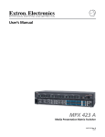
Quick Start — MPX 423 A
Installation
Step 1
Turn off power to the MPX 423 A switcher and all other devices that will be connected.
Step 2
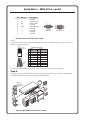
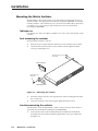
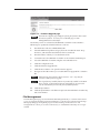
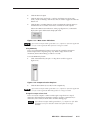
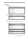
Select your mounting option and install the appropriate brackets. Mount the switcher as illustrated
below (see chapter 2, Installation for detailed instructions).
Drill pilot holes —
3/32” (2 mm) dia.
1/4” (6 mm) deep.
Mounting Screws (2 Plcs)
Each Side
Rack-mount
Bracket
-23
RS
LE
RIB
VA
or
O
IDE
S-V
L
EO
VID
L
ER
UT
MP
CO
L
T
OU
1
O IN
IDE
S-V 11
T
OU
EO
VID 7
I
N
P
U
T
S
L
L
1
2
R
L
4
L
R
L
1
2
R
L
L
3
4
R
L
1
2
R
L
3
4
R
R
3
4
R
R
O
U
T
P
U
T
S
2
C
O
N
T
T
SE
RE
R
K
LIN
O
L ACT
R
R
R
R
R
2
9
12
1
IN
3
O
I
U L
N
T
P
P
L
U
U
T
T
S
S
10
2
ER
UT
MP
CO
T
OU
5
8
6
1
ER
UT
MP
CO
IN
3
2
A
0.3
0V
1
-24
4
100
2
#8 Screw (4 Plcs)
Each Side
Table/
Wall-mount
Bracket
60
Hz
50/
Step 3
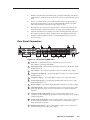
Attach up to four VGA, four S-video, and four Video (composite) input devices (up to four of each
type) to the MPX 423 A switcher.
Step 4
Connect up to two VGA, two composite video, or two S-video outputs from the switcher to a projector
or other output device. See the following page for an installation diagram.
Step 5
For audio input, connect up to 12 audio sources to the audio inputs of the VGA, Video
(composite), or S-video groups (up to four audio sources for each group). Refer to Chapter 2,
Installation, for wiring diagrams.
Step 6
For audio output, connect up to two audio output devices. Refer to Chapter 2, Installation, for wiring
diagrams.
Step 7
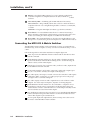
If the MPX 423 A matrix switcher is to be connected to a computer or host controller for remote
control,
1. Connect the host controller’s RS-232 cable to the 9-pin, female RS-232 remote connector of the
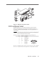
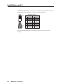
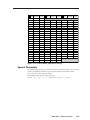
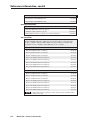
switcher (see pinout table on the following page).