1
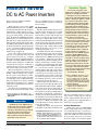
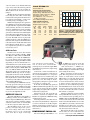
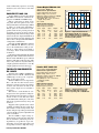
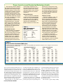
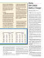
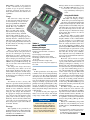
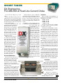
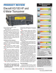
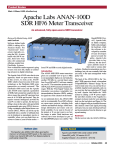
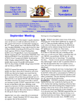
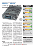
Product Review and Short Takes from QST Magazine April 2009 Product Reviews: DC to AC power inverters; Maha MH-C9000 Battery Charger. Short Takes: DX Engineering FCC050-H05-A Feed Line Current Choke Copyright © 2009 by the American Radio Relay League Inc. All rights reserved. Inverter Types product review DC to AC Power Inverters Reviewed by Howard Robins, W1HSR ARRL Contributing Editor When I became active in the ARRL Amateur Radio Emergency Service (ARES), I realized that I needed to be able to run my station during commercial power outages. A friend, I noticed, lugged an Optima AGM deep-cycle marine battery to field operations.1 I learned that AGM (absorbed glass matt) batteries are sealed, maintenance free units that do not outgas dangerous levels of hydrogen when charging and can take a beating. Unlike regular automotive batteries, they are designed for many deep charge/discharge cycles — just what’s needed for remote station operation. So, I bought one and a battery minder to keep it topped off. I have since grown my battery farm to four deep-cycle units that will source 220 ampere-hours (Ah) with an 8 A minder that works selectively with different battery chemistries, including AGM. I normally run my entire station on batteries, excluding the computer. In an emergency, I will run on commercial power as long as it is available and switch to battery power when it is not. My next thought was to add a dc-to-ac power inverter so that I could use my normal desktop computer during power outages. It’s a key part of my emergency station, used for digital modes, logging and other record keeping. I have a UPS (uninterruptible power supply) in my system, and with forethought it should keep the computer going long enough to allow me to switch to emergency power. As it turns out, the marketplace offers a wide variety of power inverters with a wide 1For more information on these batteries, see www.optimabatteries.com/optima_products/ bluetop.php. Bottom Line Modified sine wave (MSW) type inverters offer the most power capability for the money, but we found a wide variation in RF interference generated by the three units tested. The more expensive pure sine wave (PSW) units tested were both RF-quiet and generated a nice sine wave. range of capabilities and prices. First I’ll describe my initial experience, and then get into our testing. My First Inverter The first question: How much power is needed? I power all of the devices needed during an outage, including the computer, LCD monitor, printer, DSL modem and router, via a surge protected power strip. I purchased a Kill-A-Watt electric usage monitor from P3 International and connected it between my power strip and a commercial power outlet.2 I learned that all of the devices on that power strip consume about 170 W. When the monitor goes to sleep, power consumption drops by 25 W. I found all sorts of inverters on an Internet search. That was the limit of my research at the time. I got lucky when I order a 1250 W modified sine wave (MSW) type that seemed to be a bargain — much more power than I needed for a price that fit my budget. (See the sidebar, “Inverter Types,” for more information.) The inverter worked quite well. I built a transfer switch using a 3PDT relay with a 12 V coil and 16 A contacts, along with a standard duplex outlet. My power strip is now plugged into that duplex outlet, which is wired to the load contacts on the relay. The normally closed contacts on the relay are wired to a plug that goes into my UPS. The normally open relay contacts are wired to a plug that goes into the inverter. When commercial power fails, my computer system is powered by the battery in the UPS and the UPS sounds an alarm. All I have to do is turn on the inverter and switch the computer system to the ac from the inverter. The computer system keeps running with no interruption. I switch from commercial to inverter power and back routinely and have run on batteries for several hours. This works and works well. If we have a long power outage, I have a 3500 W generator that could be brought online to recharge batteries and power other essentials. Stupid things happen. One day I decided to straighten out the wiring around my radio 2www.p3international.com. Also see S. Ford, WB8IMY, “Kill-A-Watt Electric Usage Monitor,” Short Takes, QST, Jun 2006, p 61, and D. Falcon, N2JOM, “Kill-A-Watt Electric Usage Monitor Revisited,” Technical Correspondence, QST, Mar 2007, pp 67-68. Mark J. Wilson, K1RO From April 2009 QST © ARRL Product Review Editor To research emergency power options for my station, I turned to two publications available from ARRL — Emergency Power for Radio Communications and Independent Energy Guide.3,4 Each book devotes a chapter to inverters. Emergency Power for Radio Communications provides an interesting historical perspective along with practical insight into applications and use. The Independent Energy Guide provides waveforms and a more technical presentation. It includes tutorials on inverter ratings and specifications, features and options, and cost and selection. Inverters have come a long way from the early mechanical units some of you may remember from the days of tube type mobile radios. Modern technology has made inverters smaller, more efficient, less costly and widely available. Today’s solid-state inverters fall into two categories — modified sine wave (MSW) and pure sine wave (PSW). MSW inverters produce stepped square waves that resemble a sine wave. PSW inverters produce outputs that are made up of many finer steps, more closely approximating commercial ac. The difference is readily apparent in Figures 1 through 5, which show waveforms of the inverter outputs while operating under load in the ARRL Lab. — Howard Robins, W1HSR 3M. Bryce, WB8VGE, Emergency Power for Radio Communications, available from your ARRL dealer or the ARRL Bookstore, ARRL order no. 9531. Telephone 860-594-0355, or toll free in the US 888-277-5289; www.arrl.org/shop; [email protected]. 4K. Jeffrey, Independent Energy Guide, available from the ARRL Bookstore (order no. 8601, see Note 3). desk and accidentally shorted a couple of relay contacts, sending 120 V ac into the inverter output terminals. Inverters do not like ac applied to their output terminals, so I now have a big paperweight. A Noisy Replacement I found a great deal on a 2300 W MSW inverter. I figured more is better, so I ordered one and installed it in place of my first inverter. Before I powered up the new inverter, I turned on my HF radio and heard the usual levels of signals and noise. I powered up the inverter with no load and heard [email protected] Cotek ST1500-112 Serial number: n/a Manufacturer’s Specifications Power requirement: 10.5-15.3 V dc. Output voltage: 100/110/120 V ac ±3 %. Max power output (continuous): 1500 W. Waveform: Pure sine wave. Size (HWD): 4.5 × 9.3 × 15.9 inches; weight, 15.4 pounds. Price: $650 (including transfer switch) ARRL Lab Measurements Input current, no load: 1.18 A. Output frequency: 59.9 Hz. Load Input (W) (V dc) 49 12.6 358 12.3 745 12.0 1140 11.8 1515 11.5 Input (A dc) 5 32 69 111 158 Output (V ac) 121.1 120.2 119.4 118.5 117.3 QS0904-ProdRev01 200 100 Volts cant noise levels across all bands. The band scope on my radio reflected noise peaks all over the spectrum at levels exceeding S9. When I turned on the load, the noise level jumped. My first inverter generated no detectable noise using the same cables. I tried using ferrite beads to tamp down the interference to no avail. So, I sent it back — losing a 25% restocking charge and shipping costs. Further investigation got me to a pure sine wave (PSW) type of inverter. Such inverters are quite a bit more expensive than the MSW variety, but they advertise a low distortion sine wave output that more closely resembles ac line power. I wasn’t sure if they would generate less radio interference but thought it was worth trying to find out. Because of cost, I got one rated for 300 W, a closer match for my load. The PSW inverter is physically smaller but heavier than the MSW types that I had. The weight of the PSW inverter reflects the massive chokes that must be used in the filtering network. Success — it runs my computer and generates no detectable noise in my receiver. 0 -100 Eff. (%) 77.0 91.1 89.8 87.0 83.2 -200 0 0.005 0.01 0.015 0.02 0.025 0.03 0.035 Time (sec) Figure 1 — Output waveform of the Cotek ST1500-112 operating with a 1500 W load. This is a PSW type inverter; note the close approximation of a sine wave. ARRL Lab Tests For this review we chose five inverters from the many models available. ARRL Test Engineer Bob Allison, WB1GCM, assembled a pair of 105 Ah AGM batteries, a 55 A charger, and 4 foot long cables made from wire ranging from 00 to 4 AWG (depending on inverter manufacturer recommendations). To test the inverters under varying loads, he made two strings of light bulbs, each having three 300 W bulbs and one each 200 W, 100 W and 50 W. This allowed the setup to be varied from 50 to 2500 W in 50 W steps. See the accompanying tables for the test results. In addition, Bob tested the inverters for RF emissions that might interfere with Amateur Radio operations (see the sidebar, “Power Inverters and Conducted Emissions”). Load testing in the ARRL Lab was followed by practical testing at my station. My station load was a small fraction of the inverter capability, so I focused on usability and listened for noise from the inverters in my receiver. In alphabetical order: COTEK ST1500-112 The Cotek ST1500-112, from Samlex, is a PSW type inverter rated for 1500 W continuous output and 3000 W surge. This is the only inverter tested that included a built-in automatic transfer switch. At around $650, it’s the most expensive unit in this review. The ST1500 has short circuit, reverse polarity and high temperature protection. A low voltage alarm comes on when the battery sags to 11 V dc, and the unit shuts off at 10.5 V input. At the high end, overvoltage protection kicks in at 15.3 V dc. An ac circuit breaker (16 A) trips if you overload the output. Multicolor LEDs report power status, input voltage and load level. Connections, controls and indicators are on the front panel, with two cooling fans on the rear. The ST1500 has no ac receptacles and is designed to be hardwired into your system from a terminal strip behind a front panel access cover. For testing we made a short pigtail by cutting the receptacle end off a heavy duty ac extension cord. In the Lab, the ST1500 easily produced 1500 W maximum although efficiency, rated at 88% typical, dropped off above 1200 W. Output voltage was quite stable, staying near 120 V under varying loads. This inverter is the only one in this test to include a statement of compliance with FCC Part 15 requirements. ARRL Lab testing confirmed that it’s quiet. This unit produced no detectible noise at my station on any band with my computer and accessories switched in or out. My computer platform seemed happy and there were no issues when I switched between commercial and inverter ac. POWERBRIGHT PW2300-12-1 The PowerBright PW2300-12-1 is an MSW type inverter. It has the highest power rating on any of the units reviewed here — 2300 W continuous output with a surge capability of 4600 W. Selling for around $250, it’s a high power rating for the money. Battery connections are made on the rear panel. The front panel has two standard ac outlets, an on/off switch, and an overload LED indicator. A four digit display shows input dc voltage or output wattage. This meter is not mentioned in the owner’s manual. A wireless remote control unit and spare spade fuses are also included in the package. The PW2300 has short circuit and overload protection. A low voltage alarm comes on at 11 V dc, with cutoff at 10 V and 15.5 V. The unit includes a cooling fan. Our Lab test fixture ran out of steam while testing PW2300. The batteries gave up at 217 A, with the inverter providing just over 2000 W to the load. The PW2300 was starting to fade as well, down to 107 V ac from 120 V under no load, but still within its 117 V ±10% rating. Efficiency was fairly consistent in the mid-80s; we never did see the “up to 90%” stated in the literature. No-load current was only 0.24 A, the lowest in the test. This model is the same as the one I mentioned earlier, the one I returned because of noise in my receiver. The ARRL Lab From April 2009 QST © ARRL Another PSW type inverter, the Samlex PST-100S-12A is rated for continuous output power of 1000 W and 2000 W surge. Battery connections are made on the rear panel. The front panel has two standard ground fault circuit interrupter (GFCI) ac outlets, an on/off switch and LEDs to indicate power on, overload and over temperature. This inverter provides protection for polarity reversal of dc input, overload, and high temperature. The low voltage alarm activates at 10.7 V dc input with shutdown at 10 V. Overvoltage protection shuts the unit down at 16.5 V dc input. The PST-100S has a temperature controlled fan. In the Lab, the PST-100S had no problem with a 1000 W load. Efficiency was very close to the manufacturer’s rating of 85%, and the ac output voltage stayed within a 1.5 V range. At 0.5 A, the no-load current is attractive. Lab testing indicated that this unit should be RF quiet, with conducted emissions lower than the Cotek ST1500 except on 160 and 80 meters. This unit produced no detectable noise at my station on any band with my computer platform switched in or out. My computer platform seemed to be happy. TRIPP-LITE POWERVERTER PV-1250FC Tripp-Lite’s PV-1250FC is an MSW type inverter rated for 1250 W continuous and 2500 W surge. It’s also got an “overpower” rating of 1875 W for 1 hour. The PV-1250FC inverter is shaped more like a cube than the other inverters and is housed in a moisture resistant polycarbonate enclosure. All connections are made on the front, and the output uses two standard ac receptacles. This unit has a circuit breaker for overload protection and a prominent cooling fan. The unit shuts down if the input goes below 10 V dc or above 15 V dc. Two sets of three stacked LEDs, like traffic lights, on the front indicate the approximate battery charge and load level. Tripp-Lite offers optional remote control capability for turning the unit on and off. It also includes a load sensing feature. The inverter will power up when presented with a load of 150 W or so (this is adjustable and can be overridden). The PV-1250FC’s output voltage remained steady over the test range and easily met its maximum continuous power rating. Efficiency is specified at “up to 94%, depending on load and temperature” but we typically saw mid- to high 80% range. From April 2009 QST © ARRL Serial number: 060042186 Manufacturer’s Specifications Power requirement: 10-15.5 V dc. Output voltage: 117 V ac ±10 %. Max power output (continuous): 2300 W. Waveform: Modified sine wave. Size (HWD): 10.2 × 14.5 × 3.2 inches; weight, 14.5 pounds. Price: $250 Input (A dc) 6 54 114 185 217 Output (V ac) 120.2 126.4 113.6 108.6 107.0 Serial number: 07283-8GO3-0046 Manufacturer’s Specifications Power requirement: 10.7-16 V dc. Output voltage: 120 V ac ±3 %. Max power output (continuous): 1000 W. Waveform: Pure sine wave. Size (HWD): 3.3 × 9.4 × 13.9 inches; weight, 8.8 pounds. Price: $480 ARRL Lab Measurements Input current, no load: 0.5 A. Output frequency: 59.9 Hz. Input (A dc) 5 25 48 75 103 Output (V ac) 121.1 120.7 120.2 119.6 119.4 0 -200 Eff. (%) 65.3 81.0 86.8 84.7 84.2 Samlex PST-100S-12A Load Input (W) (V dc) 50 12.3 252 12.1 500 12.0 755 11.8 1006 11.6 100 -100 ARRL Lab Measurements Input current, no load: 0.24 A. Output frequency: 59.3 Hz. Load Input (W) (V dc) 49 12.5 564 11.8 1138 11.5 1734 11.1 2010 11.0 QS0904-ProdRev02 200 Volts SAMLEX PST-100S-12A PowerBright PW2300-12-1 0 QS0904-ProdRev03 200 100 0 -100 -200 Eff. (%) 81.2 83.2 87.1 85.3 84.0 0.005 0.01 0.015 0.02 0.025 0.03 0.035 Time (sec) Figure 2 — Output waveform of the PowerBright PW2300-12-1 operating with a 2000 W load. This is an MSW type inverter; note the stepped square waves and noise spikes present. Volts results confirmed my experience concerning interference; this is the noisiest of the units tested. 0 0.005 0.01 0.015 0.02 0.025 0.03 0.035 Time (sec) Figure 3 — Output waveform of the Samlex PST-100S-12A, a PSW type inverter, operating with a 1000 W load. XANTREX XPOWER 1750 PLUS The XPower 1750 Plus from Xantrex is an MSW type inverter rated for 1500 W continuous and 3000 W surge. The “1750” in the name is from its rating of 1750 W for 5 minutes. The Owner’s Guide for this unit is a little light on discussion of features. There are two LEDs on the front panel — one for POWER on, the other FAULT. In addition there is a power switch, a 3-digit meter that displays battery voltage, and a multicolor LED bar graph for output power. On the left side are three ac outlets — two grounded and one ungrounded. Battery connections and a temperature controlled fan are on the rear panel. There is an RJ-11 type jack under the front panel for a remote power switch that can be located up to 20 feet away. In addition to thermal and overload/short circuit shutdown protection, a low voltage alarm activates at 10.7 V dc input with shutdown at 10 V and 15 V dc. The FAULT LED turns red if the unit shuts down for any of these conditions. In the Lab, the XPower 1750 Plus handled a 1500 W load with no problems. The manufacturer rates “optimum efficiency” at 90%. We observed low- to mid-80% range under load. Output voltage strayed a bit but was always within specification. At 57.6 Hz, the output frequency was farther than the other units from the 60 Hz ac line standard, but within the manufacturer’s rating of ±4 Hz. In my station, this inverter produced a noticeable level of noise with no load and an objectionable amount with my load switched on. The noise with my load on was not as overwhelming as experienced with the PowerBright, however. Even so, the noise level on 75 meters increased nearly 20 dB (according to my S-meter) when I switched on my computer platform. That noise level decreased at higher frequencies, but was still audible on 10 meters. Tripp-Lite PowerVerter PV-1250FC ARRL Lab Measurements Input current, no load: 1.7 A. Output frequency: 60.2 Hz. Load Input (W) (V dc) 49 12.4 303 12.2 641 12.0 912 11.8 1230 11.6 Input (A dc) 6 29 62 87 122 Output (V ac) 122.2 119.9 120.9 120.2 120.2 QS0904-ProdRev04 150 100 50 Volts Serial number: 9732BYOPV616900003 Manufacturer’s Specifications Power requirement: 10-15 V dc. Output voltage: 120 V ac ±5 %. Max power output (continuous): 1250 W. Waveform: Modified sine wave. Size (HWD): 6.9 × 8.6 × 8.3 inches; weight, 10.5 pounds. Price: $270 0 -50 -100 Eff. (%) 65.7 85.3 86.0 88.5 86.8 -150 -0.005 0.005 0.015 0.025 0.035 Figure 4 — Output waveform of the Tripp-Lite PV1250FC (MSW type) operating with a 1250 W load. Note the relatively low noise spikes compared to the other two MSW inverters. Xantrex XPower 1750 Plus Serial number: B11636821 Manufacturer’s Specifications Power requirement: 10-15 V dc. Output voltage: 115 V ac ±5 %. Max power output (continuous): 1500 W. Waveform: Modified sine wave. Size (HWD): 3.2 × 9.4 × 17.3 inches; weight, 9.4 pounds. Price: $230 ARRL Lab Measurements Input current, no load: 0.77 A. Output frequency: 57.6 Hz. Load Input (W) (V dc) 46 12.6 443 12.1 755 12.0 1266 11.7 1538 11.5 Input (A dc) 5 45 76 130 156 Output (V ac) 115.6 113.9 111.1 110.3 117.3 QS0904-ProdRev05 200 100 Volts No-load current drain is the highest in this group — 1.7 A. In the Lab, this inverter by far had the lowest conducted emissions of the MSW inverters tested. On 160 and 80 meters, it was slightly worse than the two PSW units but emissions dropped off sharply at higher frequencies. The PV-1250FC produced no detectible noise at my station on any band with my computer platform switched in or out. My equipment seemed happy and there were no indications when I switched between commercial and inverter ac. 0 -100 Eff. (%) 73.0 81.4 82.7 83.2 85.7 -200 0 0.005 0.01 0.015 0.02 0.025 0.03 0.035 Time (sec) Figure 5 — Output waveform of the Xantrex XPower 1750 Plus (MSW type) operating with a 1500 W load. Which Inverter is for You? The answer to this question depends From April 2009 QST © ARRL Power Inverters and Conducted Emissions Limits Some electronic devices intentionally generate RF but do not intentionally radiate it. For example, RF generated by computers, receivers and switching power supplies is intentional and necessary for such devices to function. This RF, however, is not intended to be radiated as it would be by a transmitter. Under Part 15 of the FCC rules, such devices are defined as unintentional emitters. As with all Part 15 devices, unintentional emitters must not cause harmful interference to a licensed radio service such as Amateur Radio. In addition, Part 15 rules further establish the following two types of absolute limits for emissions from unintentional emitters. Conducted Emissions These emissions are conducted onto the house wiring and power lines via the device power cord. Part 15 provides absolute limits for conducted emissions from 150 kHz to 30 MHz. There are no conducted emissions limits above 30 MHz, in part because power lines are not particularly good transmission lines at these higher frequencies. Conducted emissions therefore become the primary problem when a physically large “antenna” such as power wiring is required at HF and lower frequencies. Radiated Emissions These are emissions radiated by the device itself. The absolute limits in this case are specified at 30 MHz and higher. There are no radiated emissions limits below 30 MHz. The relatively short wavelengths at 30 MHz and above are closer to the Table 1 Part 15 Conducted Emission Limits Quasi-peak detection measurements Frequency Limit (MHz) (dBµV) 0.15 - 0.5 66 to 56* 0.5 - 5.0 56 5.0 - 30.0 60 >30.0 None *Decreases with the logarithm of the frequency. physical size of a typical Part 15 device, so the device itself is more likely to act as an “antenna.” Power lines are relatively inefficient transmission lines at VHF and higher frequencies, so radiated emissions now become the primary problem. FCC Part 15 Limits FCC Part 15, Section 15.107, sets the limits for conducted emissions. Note that compliance measurements are not required for battery powered devices that are not designed to operate while connected to the ac power lines. The inverters reviewed here are the ac power source, derived from batteries, and are not required to meet conducted emission limits. Although the FCC Part 15 limits don’t apply, emissions from inverters act like conducted emissions in every other respect, and they have the potential to cause interference to radio receivers. Fortunately, the short power lines typically associated with power inverters reduce the potential for interference from conducted emissions. Using one to power an Amateur Radio station, however, can be a Table 2 Power Inverter Conducted Emissions Conducted emissions in dBµV measured in the ARRL Lab using CISPR quasi-peak detection.Shown are the six highest levels measured inside and outside the amateur bands. Cotek ST1500-112 Freq (MHz) 0.155 1.280 5.180 9.000 11.636 22.540 0 66.0 49.7 44.0 51.1 41.5 30.7 1.990 3.670 7.010 10.136 14.166 21.150 47.4 45.3 43.9 47.4 43.7 32.4 PowerBright PW2300-12-1 Load (W) 100 65.9 49.7 46.8 51.1 46.1 31.9 47.9 47.5 46.3 49.4 43.7 32.8 500 63.0 50.2 49.9 58.6 58.0 44.6 Freq (MHz) 0.150 5.639 8.330 13.257 24.326 26.166 0 114.5 68.1 79.4 75.0 70.0 72.0 48.4 49.2 50.1 59.2 51.6 46.0 1.955 7.152 14.002 24.908 28.333 28.925 87.0 82.0 71.1 69.9 69.0 68.0 upon your needs and how much money you want to invest. If your desire is to keep your computer running for a few hours, the solution is relatively simple and inexpensive. On the other hand, if you want be able to run your Amateur Radio station along with heat, refrigeration or household appliances, the solution will be more complex and costly. The two books mentioned in the “Inverter Types” sidebar can help you evaluate options. My suggestion is to start with a needs From April 2009 QST © ARRL Load (W) 100 113.2 93.0 93.0 88.0 83.5 83.5 96.2 95.4 79.6 85.5 77.5 75.7 Samlex PST-100S-12A 500 117.2 96.0 96.0 89.6 80.1 80.1 Freq (MHz) 0.161 0.657 2.170 7.331 15.149 20.500 99.1 96.6 83.0 86.0 83.0 83.5 1.815 1.953 5.319 7.145 14.321 21.3336 assessment. Determine what equipment you need to keep running during a power outage, how long you will need to run each device, and how many watts the devices use collectively. You might want to categorize your loads so that only those requiring pure sine wave get it, and loads that will work with the less expensive inverters are treated accordingly. You may also want to do a cost/benefit analysis that evaluates inverter power versus generator power given your particular power Load (W) 0 100 83.3 87.2 59.0 63.3 35.4 39.7 28.1 33.9 32.0 31.2 31.0 34.8 39.3 38.0 25.4 32.0 30.0 24.5 41.5 42.0 29.9 34.6 32.9 28.9 500 86.2 70.9 48.3 40.1 41.8 40.5 46.5 48.6 36.4 42.2 42.4 35.7 needs. Remember that the larger the load, the larger your investment in batteries, cables, charging equipment and inverter capacity. The input current at 12 V dc is roughly 10 times the output current at 120 V ac, which translates into one or more heavy duty batteries, chargers, very heavy cables, large fuses, connectors and so forth. The associated costs are significant, and the “accessories” may run more than the inverter. Also, inverter ac power ratings usually particularly demanding application. For this reason, the Lab decided that it would be useful to test the inverters using standard Part 15 procedures and instruments. This testing offers an objective way to compare emission levels among the inverters reviewed and allows direct correlation with other unintentional emitters and the FCC limits. Test Setup The ARRL Lab uses a line impedance stabilization network (LISN) and a calibrated Rohde & Schwarz ESH-3 EMC receiver to measure conducted emissions. Normally, the device under test is plugged into the LISN, which separates the unwanted RF from the desired 60 Hz ac power. The conducted emissions are then measured by the special Rohde & Schwarz receiver using CISPR quasi-peak detection.5 In the case of power inverters, however, the LISN is plugged into the power inverter. In order to accomplish this, we used a set of adapter cables to reverse the LISN input and output.6 See Table 1 for Part 15 conducted emissions limits. Note that the limits are expressed in dBµV, or dB relative Tripp-Lite PowerVerter PV-1250FC Freq (MHz) 0.150 1.664 2.500 4.667 6.020 11.847 0 102.3 66.2 56.6 42.2 37.0 16.8 1.833 3.501 3.830 7.007 14.160 29.127 63.1 51.4 47.0 31.0 18.0 6.4 Load (W) 100 108.4 66.2 55.5 42.6 36.8 16.8 62.0 53.5 48.8 31.5 22.7 6.3 to a microvolt. In this case, 1000 µV of signal equals +60 dBµV. Table 2 shows the six highest levels of conducted emissions we measured inside and outside the amateur bands with the inverters operating under a range of loads. It is important to note that Part 15 limits are not low enough to eliminate the possibility of interference but rather localize it. With power inverters, one may hear a buzzing sound across the LF, MF and HF spectrum. The severity of the interference can also depend upon such things as the placement and characteristics of the power cords and distance from the antenna. The lower the conducted emissions level, the better. — Bob A llison, WB1GCM, ARRL Test Engineer 5This measurement technique is specified in FCC Part 15. CISPR quasi-peak measurements are made using AM and a 9 kHz bandwidth and designed to assess the effect of interference of a received signal to the human ear. CISPR is the International Special Committee on Radio Interference of the International Electrotechnical Commission. 6This technique is described in ANSI Standard C63.4-2003, p 10, Figure 2. Xantrex XPower 1750 Plus 500 107.8 68.2 53.9 42.8 37.5 22.8 Freq (MHz) 0.150 1.340 2.678 7.333 13.493 26.610 0 106.5 77.7 77.0 62.1 57.0 51.2 63.9 52.0 45.5 33.0 22.3 6.4 1.856 3.656 7.161 14.015 14.171 28.289 64.3 69.2 61.2 60.8 61.3 42.3 assume a resistive load. Power factors that reduce these ratings for reactive loads, motors for example, should be considered. The Lab tested all of the inverters with an electric fan and a 580 W shop vacuum (induction motor). They all started and ran these devices with no problem. Pure or Modified Sine Wave? While MSW inverters can work at an Amateur Radio station, it is more likely Load (W) 100 106.7 83.9 79.0 65.1 67.4 52.0 83.1 71.9 76.5 66.0 63.2 37.0 500 108.2 93.0 91.8 75.8 76.7 53.9 94.9 85.3 76.7 77.0 73.0 53.8 that pure sine wave inverters will emit little or no interference, and attached electronic equipment will be happier. It is my suggestion that you look for a good quality inverter that matches your load requirements. Too much over-sizing can be costly, and it is smarter to buy the best small inverter than the largest cheap one you can find. No-load current draw and efficiency are important factors to consider, as they affect battery life. Maha MH-C9000 Battery Charger Reviewed by Ken Stuart, W3VVN ARRL Technical Advisor Do any of the following situations sound familiar? You’re getting ready for ARRL Field Day. You have the rigs ready, pencils are sharpened, pads of paper and log books packed along with everything else you can think of. You will be taking some other items such as flashlights, camp lights, or battery operated weather radios. As you grab some nickel metal hydride (NiMH) or nickel cadmium (NiCd) cells from a storage bin and stuff them into a duffle bag, you wonder whether you will get full performance from these cells, or whether some of them will quit delivering power prematurely. Or perhaps you found someone on your favorite Internet bidding site selling rechargeable cells by the carton at a price you can’t pass up. Even if some of the cells can’t hold a full charge, you know that there are probably enough that will be fully capable to justify the price. The only question is, just which cells are great performers, and which are weaklings? Also, brand new cells should be recycled a time or two to get them up to full capacity, but that takes time that you don’t have. Or maybe you have a drawer full of rechargeable batteries that you’ve collected over the years, and it’s time to check out which cells are good and which are bad. And can those that are weak possibly be restored by recycling? A Battery Charger that Analyzes Too Maha/Powerex has a charger to answer all these questions and provide top-notch charging capability as well. And it won’t break the piggy bank. Maha refers to it as the WizardOne Charger-Analyzer — the MH-C9000. Unlike other chargers on the market today that simply charge, and maybe discharge for cell “reconditioning,” the Maha MH-C9000 charger also will analyze the discharge capacity of a NiCd or NiMH cell automatically and display the results on a large LCD. In addition, the unit performs break-in of new cells as well as repetitive cycling for cell rejuvenation. The MH-C9000 will accept any mix of up to four AA and AAA cells and process them individually. It’s like having four independent single cell chargers in a single package. The From April 2009 QST © ARRL MH-C9000 is capable of other functions as well — functions that are generally not available except on expensive industrial production equipment. Specifications are shown in Table 3. Here’s the rundown of its capabilities. making it usable on most worldwide power mains. The MH-C9000 will also accept 12 V dc from a car or boat system, so it can go on Field Day and emergency events. Charge I especially like this charger’s individual cell charging circuitry. Each cell is processed based upon its own charge state and the information that it delivers to the charger. By contrast, other chargers that I have used usually charge two cells of the same case size in series. One cell may reach full charge before its mate and signal the charger to shut down the charge mode to both. This can leave one cell less than fully charged. The charger’s ability to safely refresh and analyze cells is a great advantage. I have bought a number of cells of indeterminate age and condition at a local hamfest. In particular, I acquired a dozen cells recently from one vendor and found a wide variation in their individual capabilities. After purchasing the MH-C9000, I ran about half of them through its rejuvenation cycling and found cell capacity increases of 30 to 50% after three or four cycles. Additionally, I subjected several very old NiCd cells to a few cycles and found them returned to almost full capacity. Brand new cells are known to require several charge-discharge cycles before full capacity can be realized. This is referred to as priming (or sometimes as “forming” or “formatting”) the cell.7 Off-brand manufacturers do not invest the time to perform this function as a part of the manufacturing process, so new cells are initially only capable of as little as 10% of their rated capacity. With normal use, cycling the cells improves the storage capacity. This process has been likened to the break-in period for a new car engine. Name brand cells are usually partially formatted, so that they exhibit an initial high percentage of their rating. The MH-C9000 charger can perform this formatting automatically with its BREAK-IN function. The Maha company offers this charger for the serious user of AA and AAA cells. It’s affordable for the high-end capabilities it provides. Not only is this device beneficial for Amateur Radio activities, but radio controlled model enthusiasts will also welcome its capabilities as will anyone with children and toys that greedily gobble up all those alkaline cells! Manufacturer: Maha Energy Corp, 18567 W Gale Ave, City of Industry, CA 91748; tel 800-376-9992; www.mahaenergy.com. Price: $70. This is the basic charge-only mode. A cell is inserted, and the charging rate is incremented up or down via the front panel pushbuttons in 100 mA increments from the 1000 mA default. The range available is from 200 mA to 2000 mA (yes, that is 2 A). The cell is continually monitored and the charging current, terminal voltage, and milliampere-hours (mAh) of charge acceptance are displayed. Charging stops automatically when the cell indicates that it is fully charged by exhibiting a negative voltage slope. Charging will also terminate if the cell overheats or cell voltage exceeds the maximum allowable. Refresh/Analyze This is a single-cycle rejuvenation and cell evaluation mode. Using this function exercises the cell through a top-off charge, full discharge (to 1.0 V), and full recharge. Upon cell insertion, the charger requests the desired charging and discharging currents which are set via the front panel. Defaults are 1000 mA charge and 500 mA discharge, but you can enter other values within the limits of the charger. The charger then charges the battery to its full charge state, allows it to rest for about an hour, discharges the cell to 1.0 V, and then fully recharges the cell. The charger measures stored cell capacity (mAh) during the discharge period, and displays it after the cycle is finished. Break-In Also known as battery forming, this function is provided to bring brand new cells up to their rated output or to revitalize cells that have been stored unused for three months or more. Unlike the other functions, the user is asked for the cell’s mAh rating (C). The charger then determines the appropriate charging and discharging rates, and cycles the cell. Charging is done gently at the C/10 rate (battery capacity divided by 10) for 16 hours, followed by a one hour rest period and discharge, and then recharged once again at the C/10 rate for another 16 hours. Discharge This capability is also provided if you should wish to discharge a battery manually. Discharge current can be selected from the available levels of 100 mA to 1 A. From April 2009 QST © ARRL Using the MH-C9000 Table 3 Maha MH-C9000 Battery Charger Manufacturer’s Specifications Charging current: 0.2-2.0 A, selectable in 0.1 A steps. Topoff charging current: 100 mA. Maintenance charging current: 10 mA Discharging current:0.1-1.0 A, selectable in 0.1 A steps. Discharge termination voltage: 1.0 V. Input power:12 V dc, 2 A (power supply incl) Price: $70. Cycle In this operation, the cell is subjected to a number of user selected charge/discharge cycles (up to 12). The charge and discharge currents are user entered. The CYCLE function is provided as a last ditch effort to restore aged cells that no longer accept a full charge. Occasionally, capacity can be at least partially restored by performing this cycling exercise. It can take days to perform, so it should be scheduled for a period when the battery slot(s) in the charger can be dedicated to that function. A provided external power supply furnishes 12 V dc to the charger, with an input voltage range of 100 to 240 V ac, 50/60 Hz, Bottom Line Maha’s MH-C9000 charger can help you manage your collection of AA and AAA rechargeable batteries and keep them ready for emergency use. It can also help evaluate those mystery cells from the flea market. 7For more information on priming and rechargeable batteries in general, see “Batteries in a Portable World” by Isidor Buchmann, available online at www.buchmann.ca. short takes DX Engineering FCC050-H05-A Feed Line Current Choke Gooch’s Paradox: RF gotta go somewhere. Ideally, all the RF your radio generates is radiated into space by your antenna, minus the losses that occur along the way. Problems arise when some of this radiated RF ends up in troublesome places, like on the outer braid of your coaxial feed line. I had been experimenting with a lowprofile Inverted-L antenna for 160 and 80 meters. The 140 foot L-shaped wire was shoehorned into my postage-stamp-sized back yard through the use of a couple of well placed trees at the property lines. A remote automatic antenna tuner at the base of the antenna provided multiband operation. While the antenna appeared to work well, strange things were happening back in the shack. Specifically, whenever I keyed the transceiver with more than 30 W output, the DSL Internet modem in my station went insane, as did my computer keyboard. With a little help from QST Technical Editor Joel Hallas, W1ZR, the culprit was quickly identified: My coaxial feed line was picking up RF from the antenna and transporting it back into my station. Enter the FCC050-H05-A My feed line had become an ideal pathway for common-mode currents. This was due to the fact that there was insufficient grounding at the tuner, so the coax shield acted like “one more ground wire” taking its share of the ground current back to the station. Of course, one cure is to improve the RF ground at the station. With my station being on the second floor of my house, this isn’t easily accomplished. A couple of tuned counterpoise wires in the shack would likely help, but with the station being a discreet part of the home office, I knew that solution wouldn’t go over well with my spouse. Another solution is to place an RF choke at the antenna end of the feed line. You can make one by wrapping about 20 turns of feed line into a coil, for instance, but I use heavy low-loss coax (not easily coiled) and there wasn’t much surplus length available at the antenna. I opted for a more elegant approach: the DX Engineering FCC050-H05-A feed line current choke. The FCC050-H05-A is designed for use with coaxially fed, 50 Ω antennas of many varieties including verticals with elevated radials. The choke is built like a proverbial tank, which makes sense since it is rated at 2 kW from 1 to 60 MHz. Inside the heavy duty aluminum case are two large ferrite cores through which the shielded feed line passes a number of times before making its exit. This gives the FCC050-H05-A significantly higher common mode impedance and a larger effective core area than similar line isolators, including conventional enameled wire or bead baluns. At either end of the case are SO-239 coaxial connectors. Before installing the FCC050-H05-A, I decided to test its insertion loss on several bands. Here are my results: 50 MHz = 0.6 dB 28 MHz = 0.3 dB 14 MHz = 0.2 dB 3.5 MHz = 0.1 dB As you can see, the loss rises to slightly over 1⁄2 dB at 6 meters, but that is perfectly acceptable. So far so good. I installed the FCC050-H05-A outside, right at the input of the antenna tuner. There is a terminal on the outside of the choke enclosure in case you want to connect it to a dedicated ground (such as a copper pipe) to improve performance. This isn’t necessary in most cases and I didn’t attempt it. It is important to note, however, that you should not attach your antenna ground system to this terminal. The choke case is not waterproof and DX Engineering states that this is okay. In fact, according to the instructions, “The FCC [feed-line current choke] is not affected by moisture and may be left outside in all types of weather, including heavy rain, as long as it is positioned so that water will drain from the case.” My temptation was to seal it with silicone adhesive, but after some thought I decided not to. It is obvious from the design that nothing short of total immersion in a bucket of water would be detrimental to the choke. If you do seal the case, DX Engineering cautions against using any silicone adhesives that use acetic acid (the products that have a sharp, vinegar smell) since these can corrode aluminum. Did It Work? You bet! With the FCC050H05-A at the antenna, my RF woes ceased instantly. The keyboard no longer locked up and the DSL modem performed happily even when I was running 100 W output. Despite its being exposed to the elements 24/7, I’m confident that this durable choke will provide reliable service for many years. An interior view of the FCC050-H05-A. Steve Ford, WB8IMY From April 2009 QST © ARRL Installation QST Editor Manufacturer: DX Engineering, PO Box 1491, Akron, OH 44309, tel 800-777-0703, www. dxengineering.com. $69.95. [email protected]