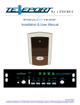
1
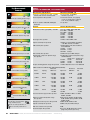
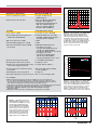
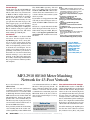
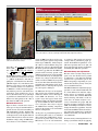
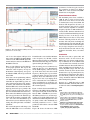
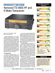
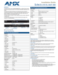
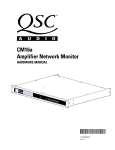
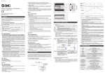
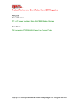
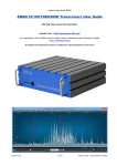
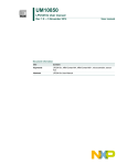
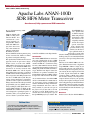
TechnicalReview Product by Mark Spencer, WA8SME Mark J. Wilson, K1RO, [email protected] Apache Labs ANAN-100D SDR HF/6 Meter Transceiver An advanced, fully open-source SDR transceiver Reviewed by Martin Ewing, AA6E [email protected] Software defined radio (SDR) is taking off in Amateur Radio. For “mainstream” transceivers (typically covering the 160 – 6 meter bands with 100 W output), there have been only a few commercial offerings, mainly from FlexRadio Systems. Now we think this market segment is going to have even more life, thanks to continuing advances in digital technology. The Apache Labs ANAN series has its own approach, based on open-source d esign. In this review, we look at the ANAN100D, which is based on some of the same technology as the FlexRadio 6000 series transceivers we recently reviewed.1 The FlexRadio 6000 series and the Apache Labs ANAN series represent a generation of SDRs built around fast samplers that are able to ingest the entire RF spectrum from near dc to 54 MHz and beyond. They do require external intelligence provided by your PC in order to operate, but the heavy lifting is done in the radio with special field programmable gate array (FPGA) devices. Using a technique called digital down-conversion (DDC), FPGAs can divide up the bandwidth into a number of subbands that can be displayed as panadapter spectra or waterfalls, where you can plunk down receivers to listen to your favorite modes — from CW and SSB to exotic digital modes. Introduction The ANAN-100D HF/6 meter transceiver gives you a detailed view of up to 1 MHz in one panadapter display on one band plus another 350 kHz in a second band, using free PowerSDR mRX PS software running on your PC. The transmitter produces up to 100 W peak (30 W maximum sustained average). With the “Pure Signal” feature, the transmitter can produce remarkably low intermodulation distortion (IMD), making its signal one of the cleanest on the bands. As we mentioned above, the ANAN-100D and its recommended PowerSDR software are open-source projects, including both software and hardware design. All the basic design information and source code are freely available, if you want to be part of the project or if you just want to see how the magic is made. Both hardware and software have been developed as part of the OpenHPSDR project (see sidebar “The Bottom Line OpenHPSDR Project”). Apache Labs, an Indian company, builds and packages the hardware, while the software is developed by a number of ham developers spread around the globe. Apache Labs provides links to key software, but the developers publish much of their work to various other websites. Finding documentation may be a challenge, but you can eventually find what you need, so the open arrangement works pretty well. The heart of the ANAN-100D is the “Angelia” SDR transceiver board, a descendant of OpenHPSDR’s “Hermes” design.2 If you want to make your own, you can buy the assembled Angelia board separately, and you can even buy the bare eight-layer PC board by itself. Apache Labs builds the ’100D system by adding a 100 W power amplifier and other circuitry to the Angelia in a compact enclosure ready for your operating desk (see the lead photo and Figure 4). The radio is shipped with pre-installed firmware (the internal control and signal processing software), but you must download software and documentation from the Internet to get up and running. Hardware On the receiver side, the ANAN-100D has Units Tested The Apache Labs ANAN-100D offers good performance in a full-featured SDR based on the open-source model. Low transmit IMD with Pure Signal enabled is particularly noteworthy. Apache Labs ANAN-100D, serial number 32186 PowerSDR_mRX_PS version 3.2.27 Angelia firmware v. 5.0. (2/18/15 – 6/13/15) QST ® – Devoted entirely to Amateur Radio www.arrl.org October 2015 45 Key Measurements Summary Table 1 Apache Labs ANAN-100D, serial number 32186 Manufacturer’s Specifications Measured in the ARRL Lab Frequency coverage: Receive, 0.01 – 55 MHz; transmit, 160 – 6 meter amateur bands. Receive, 0.100 – 61.440 MHz; transmit, as specified. 124 Power requirement: Not specified. At 13.8 V dc: transmit, 15 A (typical); receive, 2.1 A. Operation confirmed at 11.7 V dc (≥95 W RF output). Modes of operation: SSB, CW, AM, Digital, RTTY, FM. As specified. 124 Receiver Receiver Dynamic Testing Minimum discernible signal (MDS): –138 dBm. Noise floor (MDS), 500 Hz DSP BW: 0.137 MHz –130 dBm 0.475 MHz –130 dBm 1.0 MHz –135 dBm 3.5 MHz –135 dBm 14 MHz –135 dBm 50 MHz –144 dBm Noise figure: Not specified. 14 MHz, 12 dB; 50 MHz, 3 dB. Spectral sensitivity: Not specified. 100 kHz screen bandwidth: panadapter, –135 dBm; waterfall, –142 dBm. AM sensitivity: Not specified. 10 dB (S+N)/N, 1-kHz, 30% modulation, 6 kHz DSP BW: 1.0 MHz 1.16 µV 3.88 MHz 1.16 µV 50.4 MHz 0.56 µV FM sensitivity: Not specified. 29 MHz, 0.47 µV; 52 MHz, 0.20 µV. RM 117 20 60 140 20 kHz Reciprocal Mixing Dynamic Range BG 20 70 140 20 kHz Blocking Gain Compression (dB) 96 I3 97 20 50 110 20 kHz 3rd-Order Dynamic Range (dB) RM 105 60 2 140 2 kHz Reciprocal Mixing Dynamic Range 122 BG 122 70 2 140 2 kHz Blocking Gain Compression (dB) I3 96 50 2 110 2 kHz 3rd-Order Dynamic Range (dB) 20 Reciprocal mixing dynamic range: Not specified. I3 22 +35 20 -40 20 kHz 3rd-Order Intercept (dBm) I3 22 +30 -40 2 2 kHz 3rd-Order Intercept (dBm) -29* I3 TX -20 -49**‡ -35 Transmit 3rd-Order IMD (dB) -49* I9 TX -20 < -60** -70 Transmit 9th-Order IMD (dB) QS1510-PR098 80 M Key: ‡ Off Scale Intercept values were determined using –97 dBm reference. Worst case band, predistortion off. 20 M Worst case band, predistortion on. 46 October 2015 Blocking gain compression dynamic range: Blocking gain compression dynamic range, Not specified. 500 Hz DSP BW: 20 kHz offset 5/2 kHz offset 3.5 MHz 124 dB 124/122 dB 14 MHz 124 dB 124/122 dB 50 MHz 116 dB 116/116 dB 14 MHz, 20/5/2 kHz offset: 117/110/105 dB. ARRL Lab Two-Tone IMD Testing* (500 Hz DSP bandwidth) Measured Band Spacing IMD Level Input Level Measured IMD DR** Calculated IP3 3.5 MHz 20 kHz –135 dBm –97 dBm –39 dBm 96 dB –19 dBm +9 dBm +20 dBm 14 MHz 20 kHz –135 dBm –97 dBm –38 dBm 97 dB –18 dBm +11 dBm +22 dBm 14 MHz 5 kHz –135 dBm –97 dBm –39 dBm 96 dB –18 dBm +9 dBm +22 dBm 14 MHz 2 kHz –135 dBm –97 dBm –39 dBm 96 dB –18 dBm +9 dBm +22 dBm 50 MHz 20 kHz –144 dBm –97 dBm –53 dBm 91 dB –35 dBm –7 dBm –4 dBm Second-order intercept point: Not specified. 14 MHz, +65 dBm; 21 MHz, + 51 dBm; 50 MHz, +83 dBm. FM two-tone third-order dynamic range: Not specified. FM adjacent channel rejection: Not specified 20 kHz spacing: 29 MHz, 58 dB; 52 MHz, 45 dB. 10 MHz spacing: 29 MHz, 82 dB; 52 MHz, 89 dB.¹ 29 MHz, 84 dB; 52 MHz, 81 dB. Squelch sensitivity: Not specified. 29 MHz, 0.18 µV; 52 MHz, 0.09 µV. DSP noise reduction: Not specified. 10 dB. Notch filter depth: Not specified. Auto-notch, >60 dB. Attack time, 188 ms (single tone), 316 ms (two tones). ARRL, the national association for Amateur Radio® www.arrl.org QS1510-ProdRev02 0 –10 Measured in the ARRL Lab S-meter sensitivity: Not specified. S-9 signal, 14 MHz, 46.2 µV; 50 MHz, 60.9 µV. IF/audio response: Not specified. Range at –6 dB points (bandwidth)†: CW: 300 – 902 Hz (602 Hz) Equivalent Rectangular BW: 507 Hz USB, 194 – 2638 Hz (2444 Hz) LSB, 196 – 2676 Hz (2480 Hz) AM, 160 – 4988 Hz (9656 Hz) Transmitter Transmitter Dynamic Testing Power output: 0 – 100 W. As specified, except 0 – 30 W, AM. Spurious-signal and harmonic suppression: >50 dB (HF); >60 dB (50 MHz). HF, typically 58 dB, worst case 52 dB (24.9 MHz). 50 MHz, 60 dB. Complies with FCC emission standards. SSB carrier suppression: >90 dB. >70 dB. Undesired sideband suppression: >90 dB. >70 dB. Third-order intermodulation distortion (IMD): Not specified. 100 W PEP, 3rd/5th/7th/9th order: Pure Signal on (see text): –52/–54/<–60/<–60 dB (HF, typical) –52/–50/–51/<–60 dB (50 MHz) –49/–56/–59/<–60 dB (worst case, 160 m) Pure Signal off (see text): –38/–38–44/–52 dB (HF, typical) –40/–37/–44/–52 dB (50 MHz) –29/–35/–39/–49 dB (worst case, 15 m) CW keyer speed range: Not specified. 1 to 45.8 WPM, iambic Mode B. CW keying characteristics: Not specified. See Figures 1 and 2. Response (dB) –20 Manufacturer’s Specifications –40 –50 –60 –70 –80 –90 –100 fc-4 fc-2 fc+2 fc Frequency in kHz Figure 2 — Spectral display of the ANAN-100D transmitter during keying sideband testing. Equivalent keying speed is 60 WPM using external keying. Spectrum analyzer resolution bandwidth is 10 Hz, and the sweep time is 30 seconds. The transmitter was being operated at 100 W PEP output on the 14 MHz band, and this plot shows the transmitter output ±5 kHz from the carrier. The reference level is 0 dBc, and the vertical scale is in dB. QS1510-ProdRev03 0 50 MHz 14 MHz –20 SSB, 142 ms; FM, 109 ms (29 MHz), 129 ms (52 MHz).†† Transmitted phase noise: Not specified. See Figure 3. Level in dBc/Hz Receive-transmit turn-around time (tx delay): Not specified. –60 –80 –100 –120 –140 QS1510-ProdRev01 –160 Size (height, width, depth, incl protrusions): 3.3 × 10.4 × 11.1 inches. Weight, 10 lbs. –180 100 Hz Price: $3489.00. *ARRL Product Review testing includes Two-Tone IMD results at several signal levels. Two-tone, Third-order Dynamic Range figures comparable to previous reviews are shown on the first line in each group. The “IP3” column is the calculated Third-order Intercept Point. Second-order intercept points were determined using –97 dBm reference. **Third order two-tone dynamic range values shown are best case. IMD DR depends on band activity and signal strengths. See text and February 2010 QST, page 52, for an explanation. †Default values, CW 500 Hz BW, SSB 2.4 kHz BW, AM 10 kHz BW; bandwidth is adjustable via DSP. ††Default values. Turnaround times and CW delay are adjustable in PowerSDR. 0.28 0.32 10 kHz 100 kHz Frequency Offset 1 MHz 0.04 0.08 0.12 0.16 0.20 0.24 Time (s) 0.28 0.32 (A) QS1510-ProdRev01 Figure 1 — CW keying waveform for the ANAN-100D showing the first two dits in full-break-in (QSK) mode using external keying. Equivalent keying speed is 60 WPM (A) and 48 WPM (B). The upper trace is the actual key closure; the lower trace is the RF envelope. (Note that the first key closure starts at the left edge of the figure.) Horizontal divisions are 10 ms. The transceiver was being operated at 100 W output on the 14 MHz band. 1 kHz Figure 3 — Spectral display of the ANAN-100D transmitter output during phase noise testing. Power output is 100 W on the 14 MHz band (blue trace) and on the 50 MHz band (red trace). The carrier, off the left edge of the plot, is not shown. This plot shows composite transmitted noise 100 Hz to 1 MHz from the carrier. The reference level is 0 dBc, and the vertical scale is in dBc/Hz. 0 0.04 0.08 0.12 0.16 0.20 0.24 Time (s) fc+4 –40 Transmit-receive turn-around time (PTT release S-9 signal, AGC fast, 240 ms.†† to 50% audio output): Not specified. 0 –30 0 (A) QST ® – Devoted entirely to Amateur Radio 0.01 0.02 0.03 0.04 0.05 0.06 Time (s) 0.07 0.08 (B) www.arrl.org October 2015 47 two analog-to-digital converter (ADC) channels sampling the input RF (10 kHz – 55 MHz) at a 122.88 MHz rate with 16-bit resolution. Firmware defines up to seven independent receivers operating at bandwidths up to ~350 kHz that can be placed within the 55 MHz range. Output of each of these receivers can be displayed as a panadapter, waterfall, and in other ways, supporting one or two audio detectors. As a transmitter, the ’100D supports a single modulation channel with digital upconversion to the operating frequency followed by a 100 W power amplifier. Traditional modes include SSB, AM, FM, and CW. RTTY and digital modes are supported as SSB audio via additional digimode software. Software The ANAN-100D is entirely controlled through the user’s PC, excepting only the on/off switch. The recommended software for the Windows PC is the OpenHPSDR “mRX PS” extension of PowerSDR. PowerSDR is open-source software familiar to many amateurs as the basis for several SDR products, including earlier FlexRadio transceivers. For the OpenHPSDR project, PowerSDR has been enhanced by Doug Wigley, W5WC, Warren C. Pratt, NRØV, and perhaps others. The “beta” User Guide has been prepared by Ken Hopper, N9VV, and Bill Diaz, KC9XG.3 PowerSDR supports up to four receivers as two spectral displays (see Figure 5). It will allow you to “stitch” together three receivers to appear as one panadapter display covering up to about 1.05 MHz. Normally, you have a single audio channel, but in “multiRX” mode you can have two. If you’re operating split frequency, for example, you can listen to DX with one ear, and the pileup with the other. Separately, PowerSDR will support another independent receiver called “RX2,” which is normally connected to its own ADC and its own RF input jack. This can be useful for diversity reception or for monitoring a second band. your operation, but keeping up to date is a good idea. The PowerSDR mRX PS software for Windows appears to be the only fully operational transceiver software available for the ANAN-100D. However, with the open nature of the project, it is not surprising that there are other choices. I looked at two, which currently work with the ’100D for receiving, but not transmitting. CuSDR was developed for Windows by Hermann von Hasseln, DL3HVH. It provides views of the entire HF spectrum along with detailed windows for specific receiving bands of interest.5 The visual interface is modern and attractive. CuSDR is available in beta test, but it is not officially released. Ghpsdr3-Qt, developed by John Melton, GØORX/N6LYT, is another software system developed for OpenHPSDR radios. It features an interesting client/server structure that may make it easier to share work among different computers. Source or binary versions are available for Linux, MacOS, or Windows.6 These alternative projects show that it is possible for experienced programmers to develop their own back-end systems for special needs or just for fun. Computers and Networks The User Guide recommends a computer with a 2.8 GHz Intel i3 processor or better, 6 GB RAM, and a 1280 × 1024 display running Windows 7. I think PowerSDR mRX PS software should run well on most recent Windows PCs. It worked okay for me on a range of computers, from multicore Figure 4 — The ANAN-100D’s rear panel connections include three antennas, an external transverter, external 10 MHz oscillator, and amplifier PTT. Angelia’s internal computations are performed in an Altera Cyclone IV FPGA. Open source firmware for this device has been developed by Joe Martin, K5SO.4 If your radio does not have the current firmware version, you can download and install the latest one. A new version may bring new features, bug fixes, or reliability improvements that may or may not affect 48 October 2015 Figure 5 — PowerSDR offers spectral and waterfall displays, along with access to all transceiver functions. ARRL, the national association for Amateur Radio® www.arrl.org The OpenHPSDR Project The ANAN-100D’s Angelia board was developed by Apache Labs as part of the Open Source High Performance Software Defined Radio (OpenHPSDR) project, which has supported a number of limited production products for experimenters beginning in 2006.* There have been several generations of products, and the OpenHPSDR documentation is full of project names that are historically important. In particular, the Angelia board descends from an earlier single-board SDR called Hermes. Much of the original OpenHPSDR hardware/firmware development, including the Hermes transceiver, was done by Phil Harman, VK6PH. Hermes in turn incorporates technology from earlier projects such as Metis, Alex, Mercury, Penelope, and Pennywhistle. Some of this terminology is carried forward into PowerSDR’s options settings and the ANAN-100D User Guide. *See OpenHPSDR.org and S. Cowling, WA2DFI, “The High Performance Software Defined Radio Project,” QEX, May/Jun 2014, pp 3 – 13. laptops on up using Windows 7. I was able to run some experiments with my Intel Core i7 920 system with various BIOS settings. With only a single core running, PowerSDR had problems, but with two or more cores it seemed to be adequate. Your mileage may vary! PowerSDR needs a display with at least 1024 × 768 resolution. A larger display (or multiple displays) will provide screen space for logging programs, digimode software, and other operating niceties. The software has an interesting “collapsed” mode that rearranges the display into a more compact format. The ANAN-100D with PowerSDR does place a heavy load on your Ethernet as well as your PC. The User Guide recommends gigabit Ethernet, although current software versions can only support a 100 Mb/s rate. Some combinations of operating modes are prohibited because they will require more than 100 Mb/s. For example, you can’t stitch radios or use 384 Kb/s sampling while using the Pure Signal feature. More of these “corner cases” should be supported when 1000 Mb/s (gigabit) Ethernet is implemented. You can connect your computer and the ’100D to your home network router, but if needed you can use an isolated Ethernet connection with no router at all. Documentation The first thing to do after you unpack the ANAN-100D is to download the User Guide, which is well-written but rather uneven in its coverage.7 To use the Guide effectively, it helps to know your way around PowerSDR and some of the OpenHPSDR lingo. If PowerSDR is new to you, I would recommend reading the manual (software parts) for the FlexRadio Systems FLEX-5000, which has a similar user interface.8 (The Flex document is a fine example of a comprehensive user manual.) Thorough documentation is hard work, and it can be a difficult thing to accomplish in distributed open source projects. Most of the information you might want about PowerSDR and the ANAN-100D is available on the Internet, but some of it is fragmented across various websites, and those websites may not be quite in sync. You may need to ask the users and gurus on the Yahoo Apache-Labs group.9 There is also a notable wiki site that compiles useful links and documents.10 Many options are available through the setup menus, but unfortunately the User Guide does not explain all of them. Some major items, such as the ALEX button are not explained anywhere. (It enables automatic receiver filter switching.) I would prefer that the more exotic and experimental options be hidden unless you enter an “expert” mode; otherwise a newbie is tempted to twiddle settings and possibly set bad operating conditions or get lost in the forest of options. Some settings seem to apply to unfinished development work that should probably not appear in “production” software. (Sometimes open source can be a little too open!) It’s not too much to expect that all controls should be documented, with a clear explanation of whether special capabilities like CESSB or Pure Signal should be considered the default choice for normal operation. Operating Modes For CW operation, PowerSDR includes an iambic keyer function claiming to cover 1 to 60 WPM, so you only need to attach your paddle or straight key. Unfortunately, we found that the ANAN-100D (with current software) was not able to reliably track either the internal iambic keyer or an external keying signal above about 48 WPM. Figure 1 shows the problem when we try to run our standard 60 WPM keying test. CW with the internal keyer was good in the 20 – 30 WPM range that I normally send with a paddle. The audio sidetone is in sync with the RF output without perceptible delay. Sidetone pitch can be varied from 200 to 2250 Hz. Semi-break-in operation is provided, with a variable transmit hold time. Typical of SDR transceivers, the long transmit/receive switching time prevents full break-in (QSK) operation. In CW mode, PowerSDR provides an adjustable audio peaking filter (APF) that can tailor the audio response to your liking. You can manually zero beat with another station by visually tuning to the IF band center, and if reception is clear enough, you can use the 0 BEAT button to automatically center the signal. PowerSDR also sports a CWX feature that allows you to send CW from preset buffers or “live” from your keyboard. This should help for contesting or for any Morse keyboarding. For voice operation, the ANAN-100D provides a front panel 1⁄8-inch jack for microphone and PTT (push to talk). The User Guide helpfully explains how to connect various microphones. You can select optional “phantom” bias and change the pin-out by setting on-board jumpers. (Unfortunately, changing Angelia’s jumpers requires a tricky disassembly of the ’100D.) Alternatively, you can connect line level audio and PTT through the back panel DB-25 connector. It took me a while to figure out how to use a low-output microphone. It required not only selecting +20 dB boost, but also increasing the MAX GAIN setting on the transmit setup dialog. SSB and AM modes offer a selectable gain compression to increase average “talk power.” There is also a “downward expansion” option that acts as a noise gate — quickly attenuating the audio when the input level falls below a certain level, helping control background noise. In addition to QST ® – Devoted entirely to Amateur Radio www.arrl.org October 2015 49 gain compression, a special “CESSB Overshoot Control” option is available to minimize overshoot peaks that would otherwise limit the maximum power.11 An audio equalizer provides either 3- or 10-band adjustment of frequency response separately for transmit and receive. Some of the audio characteristics can be stored in “transmit profiles,” which are labeled storage areas that allow you to switch your configuration between, say, normal and DX modes. (DX might need more compression and less bass response to give more punch, for example.) AM is supported on receive with filters up to ±10 kHz bandwidth, providing good results on broadcast stations, especially in the SAM (synchronous AM) mode. Transmit filters can also be set to pass modulation up to 10 kHz. If you ask for more than 3 kHz (all that is needed for normal voice communications), you will get a mild scolding from PowerSDR, but you can use all 10 kHz. The ’100D with PowerSDR supports FM voice operation with either 2.5 or 5.0 kHz deviation. A convenient control panel allows you to select CTCSS tones and repeater offsets, including normal, reverse, and simplex. A MEMORY tab brings up a window that lets you remember all the relevant settings for an operating channel, such as a repeater. (This feature is handy for storing commonly used frequencies and settings for any mode.) An adjustable squelch control is available on any mode, but will be particularly important for channelized FM work. There is no tuning indicator to show carrier offset, but you can see the offset on the panadapter during a pause in modulation. For digital QSOs, you can use the ANAN-100D with Fldigi, WSJT-x, and similar software. The convenient way to operate with these sound card modes is to internally connect the digimode software with PowerSDR using Virtual Audio Cables.12 VAC operation requires no sound cards, but you will need to obtain some additional software. The PowerSDR-Fldigi writeup also gives some clues about the ’100D CAT interface, which is not otherwise documented, apart from the FLEX-5000 guide. tions. The output level is fairly low, about –10 dBm. PowerSDR provides a flexible antenna switching matrix and transverter setup dialog that lets you specify the frequency and gain relationships for up to 13 different transverters. You can also make use of programmable band select outputs to control transverters, antenna relays, or other gear. Diversity Reception With the VFO SYNC button, you can force VFOs A and B to the same frequency. The two receiver channels (RX1 and RX2) can then be used with separate antennas in two different diversity modes. You can receive RX1 in one ear and RX2 in the other (using the PAN adjustments). Signals then seem to come from different directions, and that may help you dig the desired signal out of the noise and QRM. When the signal fades out in one channel, it may still be audible in the other, depending on how independent your antennas are in terms of spatial separation, polarization, and so on. The ANAN-100D also supports a diversity combining mode. This adds the RX1 and RX2 signals together with adjustable phase and amplitude. You can use this simply to Taming IMD with Predistortion Linearization (Pure Signal) Intermodulation distortion (IMD) is a problem for transmitters because it causes audible distortion of your voice or multi-tone digital signal, and it causes your signal to broaden and interfere with other stations near your frequency. For years, engineers have used the technique called “predistortion linearization” to reduce IMD in commercial RF power amplifiers.† We present a quick overview here. To our knowledge, the “Pure Signal” feature of PowerSDR, as implemented by Warren C. Pratt, NRØV, is the first application of predistortion linearization to a commercial Amateur Radio HF transceiver.†† Pratt received the 2014 ARRL Technical Innovation Award for this work. Part A of Figure A offers a graphical view. Your “linear” amplifier is never quite linear — that’s what produces IMD. It might have some power compression at high power as shown by the “Amp” curve in the figure. If we introduce predistortion before the amplifier with a matching power expansion characteristic, the overall result should be much improved linearity. The amplifier’s power transfer curve will vary depending on operating conditions, so a fixed predistortion won’t do. With good software, your radio can continuously compare the RF output with the desired waveform and adjust the predistortion as needed. Part B of Figure A is a basic block diagram. The receiver operates during transmission allowing control software to adapt to changing conditions. Everything you need is provided in the ANAN-100D with PowerSDR Pure Signal feature. You can also use it to linearize an external power amplifier, but you will have to feed back a small sample of the amplifier’s output to the receiver with some extra hardware. Predistortion linearization is a fascinating development that can work particularly well in SDR radios like the ’100D, helping you transmit a cleaner signal, improve your audio quality, and reduce QRM for everyone. †www.highfrequencyelectronics.com/Sep04/HFE0904_Nezami.pdf ††www.wavenode.com/PureSignal.pdf Figure A — Predistortion linearization method graphical concept (A) and simplified block diagram with adaptive control (B). For 2 meters and higher frequencies, you can set up the ANAN-100D to work with external transverters. The ’100D has dedicated transverter input and output connec50 October 2015 ARRL, the national association for Amateur Radio® www.arrl.org There is an auto notch filter (ANF) that will try to eliminate steady interfering tones — “heterodynes” as we knew them of yore. The binaural (BIN) option separates the audio reception into two components for left and right headphones. It produces a pleasing stereo effect. I’m not sure if it improves copy, but it won’t hurt! The Power SDR setup options give you the chance to experiment with many different settings for the NR and ANF functions. There are two noise blanking functions — NB or NB2. They generally work by snipping out a short piece of audio when there is a brief noise peak. Depending on your situation, you may benefit from one option or the other. PowerSDR has an RA (radio astronomy) option. As a radio astronomer in a former life, I found that intriguing. With this feature, you can measure what we would call “total power” — the sum of the power across frequency channels. This is averaged, written to a disk file, and graphed against time. Astronomically, you might record the response as the Sun or Moon drifts through the beam of your VHF Yagi, helping you check the pointing of your antenna and the sensitivity of your system. Moving back to Earth, you might monitor your interference level throughout the day. Another feature of the ANAN-100D is the setup option for your operating region. Regions are predefined for many countries. The one you choose determines the allowed operating bands, modes, and license classes. There is also an “extended” region that allows transmission on any frequency, Making use of the extended region, we did some quick tests transmitting on the proposed 630 meter and 2200 meter bands. We got around 100 W output at 475 kHz, and about 40 W at 137 kHz. The transmitter has high harmonic output, however, because it lacks the correct low-pass filters for those bands. You would have to supply your own filters when the bands open up to Amateur Radio. For contest operators who need to reduce the complexity of working with computer logging systems, PowerSDR implements a FocusMaster feature that returns mouse/ keyboard focus to a supplementary program such as the N1MM+ logger after a radio operation is completed. Receiver IMD The ANAN-100D, like some other SDR receivers, shows a two-tone third-order dynamic range that depends on the level of activity and signal strengths in the RF pass band of the receiver, as explained in the QS1510-ProdRev06 0 –10 –20 Response (dB) Other Features PowerSDR provides two interesting noise reduction options — NR and NR2. They both offer the ability to help signals stand out from noise. They sound rather different, so you need to try both of them to find what works for you. I found that NR2 was particularly good in some conditions. It has a somewhat unnatural sound, but it was effective. which should only be used with care. You are always responsible to be sure that on-air operation is confined to bands and modes that are legal for your license. –30 –40 –50 –60 –70 –80 –90 –100 fc-4 fc-2 fc+2 fc Frequency in kHz fc+4 (A) 0 –10 –20 Response (dB) gain a bit of signal to noise with two antennas, or you can use it to null out an interfering signal. With some tricky settings you can create a deep null in a particular direction that can help you eliminate a specific source of interference. It can be hard to find the null if propagation is varying too much, but I achieved a 35 dB null on a local broadcast AM station. –30 –40 –50 –60 –70 –80 –90 –100 fc-4 fc-2 fc+2 fc Frequency in kHz fc+4 (B) Figure 6 — ANAN-100D during normal operation (A) and with Pure Signal on (B). February 2010 issue of QST, page 52. The values in the data table are the best observed dynamic ranges. Typically, on a quiet band, the user will have a third order IMD dynamic range of about 65 dB. Transmitter Linearity The ANAN-100D with PowerSDR offers a very interesting transmitter IMD-reduction feature called “Pure Signal” (PS), implemented by Warren C. Pratt, NRØV, and based on the principle of predistortion linearization. (See the sidebar, “Taming IMD with Predistortion Linearization (Pure Signal.”) IMD improvements measured in the ARRL Lab were dramatic. A typical IMD measurement before and after applying Pure Signal is shown in Figure 6. The typical 3rd order IMD without PS was a respectable –38 dB (Figure 6A), but with PS IMD it was an exceptional –50 dB (Figure 6B) — the best we’ve ever seen in the Lab. Pure Signal is provided on an “opt in” basis. You need to set it up and enable it before using. At some point, we would hope that a feature like this will be well enough established that it will be the default choice for modes requiring good linearity — AM, SSB, and some digital modes. Frequency Reference The internal frequency reference is a ±0.1 ppm TCXO, which is excellent for most amateur work. In a normal working environment, you can expect stability somewhat better than this. PowerSDR offers an automatic frequency calibration against an external signal such as WWV, but you can do better with Fldigi software. On our unit, I measured an offset of about 0.04 ppm against WWV at 20 MHz. The ANAN-100D offers the ability to work with an external 10 MHz oscillator as a reference, which may be helpful if you want to run a VHF+ station from a common oscillator or if you have a GPS disciplined oscillator. To switch from internal to external reference requires changing jumpers on the Angelia board, which (again!) means disassembling the radio. (Apache Labs notes that the ANAN-200D model does not require opening the case and moving jumpers for the 10 MHz reference or mic/bias adjustments.) Apache Labs sells a small add-on daughter card for the Angelia that provides automatic switching between internal and external references, if you need it. QST ® – Devoted entirely to Amateur Radio www.arrl.org October 2015 51 Thermal Design Apache Labs rates the ANAN-100D for a maximum continuous output of 30 W, which could affect long transmissions on RTTY or FM for example. This is apparently due to the limited air circulation and use of the radio’s case as a heat sink. Running at 30 W continuously, the case gets quite hot to the touch. If you go to the Yahoo support group, you will find ideas to improve cooling and increase operating power, such as drilling holes or adding fins. But the standard cooling fan is quiet and fine for lower duty cycle voice, CW, or data modes running up to 100 W peak. Conclusions The ANAN-100D is an advanced SDR transceiver that developed from the OpenHPSDR project. It has a strong heritage as an “open” system, where you have access to all the design information and where, more importantly, you have access to advanced users and designers. You are joining a project almost as much as you are purchasing a radio. That’s good, because it means there are a lot of new features being hatched, and help is easy to find. Some amateurs, on the other hand, might prefer the stability and thorough documentation that you get with more traditional products and companies. The ANAN-100D’s operating “look and feel” is very similar to the last-generation FlexRadio 3000/5000 SDR radios because of their shared PowerSDR interface. It is a mature and time-tested software system that is very usable. If you hanker for a high performance SDR radio and you lean toward open source solutions, the ANAN-100D could be the radio for you. Manufacturer: Apache Labs Pvt Ltd, 1023 Tower B4, Spaze I-Tech Park, Sector 49, Sohna Road, Gurgaon 122001, Haryana, India; e-mail [email protected]; apache-labs.com. Available from several US dealers. Notes 1M. Ewing, AA6E, “FlexRadio Systems FLEX6300 Transceiver, FLEX-6700 Transceiver, and SmartSDR for Windows Software,” Product Review, QST, Apr 2014, pp 47 – 59. 2apache-labs.com/productPdf/1031_Angelia. pdf 3apache-labs.com/download_file. php?downloads_id=1017 4www.k5so.com/HPSDR_downloads.html 5plus.google.com/107168125384405552048/ about 6openhpsdr.org/wiki/index.php?title= Ghpsdr3-Qt 7apache-labs.com/instant-downloads.html 8goo.gl/JbC5g5 (pdf) 9groups.yahoo.com/neo/groups/apache-labs/ info 10anan-100d.wikidot.com 11D. Hershberger, W9GR, “Controlled Envelope Single Sideband,” QEX, Nov/Dec 2014, pp 3 – 13. 12groups.yahoo.com/group/apache-labs/ files/PowerSDR-Fldigi_Guide_V2.0.pdf See the Digital Edition of QST for a video overview of the Apache Labs ANAN-100D SDR HF/6 Meter Transceiver and PowerSDR_mRX_PS. MFJ-2910 80/160 Meter Matching Network for 43-Foot Verticals Reviewed by Phil Salas, AD5X [email protected] When fed with a 1:4 unun (unbalancedto-unbalanced transformer), the 43-foot vertical antenna has a reasonable SWR on 60 through 10 meters, thereby keeping SWR-related losses low on those bands. On 160 and 80 meters, however, this antenna provides such a severe mismatch that you will throw away most of your power in your coax and unun on these bands because of the extreme SWR-related losses. I have previously written articles describing a base matching unit for the 43-foot vertical that significantly reduces SWR-related 52 October 2015 coax and unun mismatch losses on 160 and 80 meters, while preserving the 60 – 10 meter compromise SWR of the original antenna.13, 14 For those who do not wish to undertake that construction project, the MFJ-2910, shown at the base of the author’s 43-foot vertical in Figure 7, is an option to consider. Bottom Line The MFJ-2910 provides a worthwhile addition to 43-foot vertical for those who wish to use this antenna on 160 and 80 meters. ARRL, the national association for Amateur Radio® First, a Discussion on RF Voltages The MFJ-2910 is rated for 1.5 kW PEP or 750 W continuous RF power on all amateur bands from 160 – 6 meters. The power limitations are due to the extremely high voltages and high currents that can be generated because of the low radiation resistance and high reactance of this antenna on 160 meters, and the finite Q of the matching inductor. As it is important to understand the high voltages and currents that can occur, a discussion of the calculations is in order. You will be matching your amplifier power into the sum of the radiation resistance (Rr), inductive losses (Rind), and ground www.arrl.org Table 2 160 Meter Inductor Performance 160 meter inductor loss and peak voltage vs ground loss at 1500 W Assumptions: radiation resistance, 3 Ω; antenna reactance, –j 600 Ω; inductor loss 2 W Ground Loss RF Current Inductor loss Peak Voltage at Antenna Base (Ω)(ARMS )(W) (VPK) 0 10 15 17.32 10.0 8.66 600 200 150 14,700 8,500 7,400 Figure 8 — Inside the MFJ-2910. The unun, relays, and coils are visible. The black material on some of the relays is a silicone sealant type material that helps support the inductor. Figure 7 — MFJ-2910 connected to the base of the reviewer’s 43-foot vertical. losses (Rg) — Rtotal = Rr + Rind + Rg. Since Power = I2R, I = P / R total and so inductor loss = I2Rind. Finally, the peak voltage is = Z R total 2 + X 2 . VPK = 2 × Z × I where From EZNEC modeling software, a 43-foot vertical antenna has an impedance of about 3 – j 600 Ω on 160 meters. And when inputting the coil dimensions into HamCalc (300 mm length × 45.7 mm diameter, wire diameter = 1.65 mm, N = 94), the inductor has a calculated resistive loss of about 2 Ω on 160 meters.15 Table 2 shows the approximate inductor power loss and antenna base peak voltage versus ground losses. As you can see, the inductor loss can get quite high as ground loss is reduced. However, average inductor loss will typically be 20 – 30% of that shown for SSB or CW operation. MFJ-2910 Discussion Figure 8 shows a network of 13 relays to select taps on a large air-wound inductor to provide 43-foot vertical base-matching on 160 and 80 meters. On 60 – 10 meters the relay network bypasses the inductor, and so the input reverts to the original unun-fed antenna. The relays have contact-to-contact breakdown voltage ratings of 1000 VRMS, and contact-to-coil breakdown voltage ratings of 5000 VRMS. Six sets of relay contacts in series protect against arcing on 160 meters (up to 8500 VPK). And to improve the contact-to-coil breakdown voltage, the affected relay coils are disconnected from RF and dc ground on 160 meters. Further, a 1⁄4-inch arc-gap built into the MFJ-2910 printed-circuit board may provide some additional protection, but it will probably not arc before the relays are damaged. Note that the relay voltage break-down ratings will be exceeded at 1500 W if your ground loss is lower than about 10 Ω and you have negligible tuner and feed-line losses. In all fairness, however, achieving 10 Ω ground loss can be quite a challenge.16 On 160 meters all relays are de-energized, thus selecting the maximum loading coil inductance and the correct shunt tap for lowest SWR. On 80 meters, –12 V energizes relays that bypass much of the 160 meter loading coil and change the shunt tap for best SWR. For 60 to 10 meters, +12 V energizes other relays to bypass the 160/80 meter matching components and revert the antenna to its normal 60 to 10 meter configuration. All dc power is provided through the interconnecting RF cable via an included three position bias-T (MFJ-4118). An isolated 12 V dc power source, such as the MFJ-1316 or 12 V dc wall transformer, is required as both positive and negative voltages must be provided for proper operation. About 60 mA is required for –12 V (80 meter operation) and +12 V (60 – 10 meter operation). No current is required for the default (0 V) 160 meter operation. MFJ-2910 Setup and Adjustments Because of the very high voltages developed across the antenna base-to-ground on 160 meters, a new fiberglass-insulated antenna base is provided as part of the MFJ-2910 package. Depending on your antenna base insulator, you may or may not elect to install this new base. The MFJ-2910 must be adjusted for proper operation as each antenna installation will be a little different. To make the adjustments, remove six externally accessible screws and two nuts, slide the MFJ-2910 from its housing, and mount it to the antenna base. An antenna analyzer is necessary to determine the proper 160 and 80 meter resonance frequencies and best SWR. A #2 Phillips screwdriver is used to change the inductor tap positions. You will need to take the MFJ-4118 bias-T and a battery pack to the antenna base to enable the different bands while you make the necessary adjustments. Note: Incorrectly connecting the bias-T can damage your antenna analyzer by applying QST ® – Devoted entirely to Amateur Radio www.arrl.org October 2015 53 performance I achieved (again, based on my ground loss of about 13 Ω). With an SWR of 3:1 or less across the band, SWRrelated losses are negligible. Some Final Observations The maximum power I have available is 1200 W, and no arcing occurred at this power level. It was nice to not even need an antenna tuner on my selected 160 and 80 meter CW frequencies! Of course, an in-shack antenna tuner will be needed with a solid-state amplifier for extendedfrequency operation on 160 and 80 meters, and also for 60 – 10 meters with the 43-foot vertical’s standard unun matching network. (A) Finally, because of the design of the MFJ-2910 you won’t have to worry about moisture collecting inside the unit. Any moisture will easily drain out through the bottom/connector side of the unit. My only concern is that the holes in the bottom plate may be large enough for some insects to move into the unit over time. Ants are a big problem in the Dallas, Texas, area where I live. (B) Figure 9 — MFJ-2910 160 meter SWR performance is shown at (A), and the 80 meter SWR performance is shown at (B). ±12 V dc to the analyzer’s RF port. You must connect the MFJ-4118 RF/DC OUT/IN connector to the MFJ-2910 RF input. The antenna analyzer connects to the MFJ-4118 RF IN/OUT connector. I found that the cover raised the 160 meter center frequency by 50 kHz, and the 80 meter center frequency by 25 kHz. Keep this in mind when selecting your center frequencies during the tuning process. There are four inductor taps that must be set for proper operation. One tap sets the 160 meter center frequency, one tap sets the 80 meter center frequency, one tap sets the 160 meter SWR, and one tap sets the 80 meter SWR. Start the tuning process on 80 meters by setting the bias-T to –12 V. Determine the lowest SWR frequency and move the top tap on the short coil to move the resonant frequency. Moving the tap toward the ground end of the coil raises the resonant frequency. Next select 160 meters by setting the bias-T off, or just unplug the dc source. Determine the lowest SWR frequency and adjust the tap on the long coil. Again, moving the tap toward ground raises the resonant frequency. I have done a lot of experimenting with my own 160/80 meter matching unit, and I’ve found that the input SWR tap points are quite consistent from unit-to-unit, antennato-antenna, and installation-to-installation. With the MFJ-2910, connect the 80 meter input tap (the closest tap to ground) to the 8th wire from the ground end of the coil (the count should include the bottom wire). Then connect the 160 meter input tap point (the next tap point above the 80 meter tap) to the 13th wire from the ground end of the coil — five wires above the 80 meter tap. I believe that if you start with these input tap settings, they will require little or no further adjustment. The resonant frequencies will change a bit when the MFJ-2910 cover is re-installed. 54 October 2015 Figure 9A shows the measured SWR performance of the MFJ-2910 on 160 meters. As I operate mostly CW, I centered the unit between 1800 – 1850 kHz. As you can see, the SWR stays below 2.5:1 over this range, resulting in negligible SWR-related coax and unun losses when using RG-213 or better quality coaxial cable. Incidentally, my measured ground loss is 13 Ω — a lower ground loss will result in a narrower SWR bandwidth. Figure 9B shows the 80 meter SWR ARRL, the national association for Amateur Radio® Conclusion For those who want to operate 160 and 80 meters with a 43-foot vertical, the MFJ-2910 is one solution worth considering. It eliminates the severe SWR-related coax and unun losses normally associated with this antenna on those bands. However, while the MFJ-2910 will handle the extremely high RF voltages that will occur with this electrically short antenna when mounted over a typical ground system, very well-designed ground systems that achieve less than 10 Ω ground loss may result in voltage breakdown within the MFJ-2910 when running full legal limit. Manufacturer: MFJ Enterprises, 300 Industrial Park Rd, Starkville, MS 39759; tel 662-323-5869; www.mfjenterprises. com. Notes 13P. Salas, AD5X, “160 and 80 Meter Matching Network for Your 43 Foot Vertical,” QST, part 1, Dec 2009, pp 30 – 32; part 2, Jan 2010, pp 34 – 35. 14P. Salas, AD5X, “160- and 80-Meter Matching Network for Your 43-foot Vertical – UPDATED,” available from www.ad5x.com (look in the Articles section). 15hamwaves.com/antennas/inductance.html 16R. Severns, N6LF, “Vertical Antenna Ground Systems at HF,” available from www.kkn.net/ dayton2004/HF_vertical_ground_ system_design_N6LF_Dayton.pdf www.arrl.org