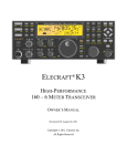
1
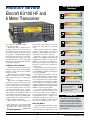
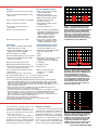
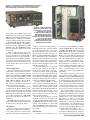
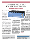
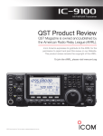
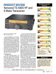
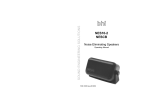
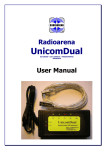
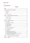
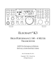
ВСЕ НОВОСТИ НА www.rv3apm.com/rxdx.html www.rv3apm.com/rv3apmrus.html Product Review and Short Takes from QST Magazine January 2009 Product Reviews: Elecraft K3/100 HF and 6 Meter Transceiver Short Takes: bhi Radio Mate Keypad for Yaesu FT-817, 857 and 897 Transceivers Copyright © 2008 by the American Radio Relay League Inc. All rights reserved. Key Measurements Summary product review Elecraft K3/100 HF and 6 Meter Transceiver 142† 142† 140 20 70 20 kHz Blocking Gain Compression (dB) 139 2 140 70 2 kHz Blocking Gain Compression (dB) 108 I3 106 110 20 50 20 kHz 3rd-Order Dynamic Range (dB) I3 Reviewed by Joel R. Hallas, W1ZR Technical Editor, QST The Elecraft K3 is a modular and expandable transceiver that can be set up to fill a number of roles. In our first look, we described a configuration at the bottom of the K3 spectrum — a 10 W minimally equipped kit version of the transceiver.1 At that time, many of the announced options were not yet available. This time, we have waited until almost all of the bells and whistles have been installed and configured. In addition to the pieces included for the earlier review, this version has the following hardware as well as the benefit of multiple firmware revisions: An internal power amplifier module (KPA3) that makes the K3 into a nominal 100 W output transceiver on 160 through 6 meters. A second receiver (KRX3), identical in performance to the first, that fits in the same box. Two audio channels are provided so one receiver can be heard in each ear or speaker, or they can be mixed. In split mode, one receiver can track a DX station’s receive frequency and control the transmit frequency, while the other is listening to his transmission. The two receiver VFOs can be locked together to provide diversity reception to avoid fading. This works if you have two separated antennas or antennas of different polarization. A transverter interface (KXV3) that also provides a connection for a receive-only antenna and an IF output for a spectrum scope. An automatic antenna tuner (KAT3) specified to match antenna loads with an SWR up to 10:1. The KAT3 also provides a switchable second antenna connection. General coverage receiver front end band-pass filter (KBPF3), AM, SSB, CW and FM roofing filters (see text) and the KTCXO3-1 temperature controlled frequency reference that provides stability of better than ±1 ppm over the operating temperature range. The only announced options that weren’t yet available for testing were the digital voice recorder (KDVR3) and the low noise 6 meter receive preamp (PR-6). The resulting radio looks the same as the K3/10 from the front, but it weighs a tad more and the rear panel has quite a few more connectors. As you might expect, the options result in a significant increase in the total cost. While the base 10 W kit costs $1400 at this writing, our fully assembled and tested radio is about $4000 ($3350 for the radio and modules, plus $600 for five optional roofing filters). A nice feature of the K3 architecture is that it doesn’t have to be purchased all at once, nor are all options required to have a fully functional competitive transceiver — build it your way. Start with as much of a chunk as you’re comfortable with and then add pieces over time. It also makes filling out holiday wish lists an easy chore, possibly for years to come! 1B. Does Size Matter? So What’s in This Little Box? Prior, N7RR, “First Look: Elecraft K3 HF/6 Meter Transceiver,” Product Review, QST, Apr 2008, pp 41-45. QST Product reviews are www.arrl.org/ members-only/prodrev/. available on the Web at We should emphasize that this is indeed a compact and, at just a few pounds more than the K3/10, still a light transceiver. At Mark J. Wilson, K1RO Product Review Editor 2 103 110 50 2 kHz 3rd-Order Dynamic Range (dB) 28 I3 29 +35 20 -40 20 kHz 3rd-Order Intercept (dBm) I3 2 28 +35 -40 2 kHz 3rd-Order Intercept (dBm) I3 TX -20 -29 Transmit 3rd-Order IMD (dB) -35 I9 -51 TX -20 pr036 -70 Transmit 9th-order IMD (dB) Key: † Off Scale Dynamic range and intercept values with preamp off. Intercept values were determined using -97 dBm reference 80 M 20 M Bottom Line The K3, in any of the available configurations, provides a high performance, modular and expandable transceiver that can fill the needs of almost anyone looking for an HF and 6 meter transceiver for home station or portable use. [email protected] From January 2009 QST © ARRL a size about the same as the compact entry level radios from other manufacturers, this radio includes many features found in the largest and most expensive radios on today’s market. Its performance is comparable or superior in most respects as well. On the other hand, there just aren’t as many knobs and switches on the front of this radio as its larger brethren. Elecraft uses each button for at least two functions. The one shown on the button happens with a quick tap. A secondary, often related, function, shown below the button, is enabled with a longer, 1⁄2 second or more, push. It doesn’t take long to get the fingers programmed. The buttons and knobs are organized into groups by function, and I had no problem getting to know them. While size and weight are of particular importance to those who want to take the radio with them as they travel, or who operate in close quarters, front panel space is limited. Controls are somewhat smaller and closer together than on some larger radios, although I found them all accessible and easy to use. Perhaps the display provides the biggest difference. The K3 includes a two-line monochrome LCD that shows all critical operating information. It doesn’t offer the bells and whistles of the “big boys,” particularly a spectrum analyzer — perhaps expected at the upper end of the K3 price range. An IF OUTPUT jack is provided (as part of the optional KXV3 transverter module) so that an external spectrum scope can be supported. At least one manufacturer provides a very competent one that works with a PC and provides “point-and-drag,” frequency selection.2 Thus, with an added spectrum scope for home station operation, the combination of displays can rival top-end transceivers. At the same time the basic radio remains ready for the campground or emergency operations center. For some, this will be the best of all worlds. Those who don’t travel or don’t need the compact footprint may wish it were somewhat larger. How’s it Play? In a word, this is one fine radio. I was so impressed with its published performance that I will happily confess to having purchased a 100 W kit version for myself. I don’t think that makes me biased, since I’ve had much more cockpit time to get to know the K3, for better or worse, than most equipment I’ve reviewed over the years. The ARRL Lab measurements were taken with a current production radio. We’ve also spent quite a bit of time using an early production K3/100 that’s been upgraded as accessories and new firmware have become available. 2LP-PAN software defined IQ direct conversion panadapter for the K3. Available as a kit or fully assembled from Larry Phipps, N8LP, at www.telepostinc.com. From January 2009 QST © ARRL Table 1 Elecraft K3, serial number 1915 Manufacturer’s Specifications Measured in the ARRL Lab Frequency coverage: Receive, 0.5-30, 48-54 MHz; transmit, 1.8-2, 3.5-4, 5.33-5.40, 7-7.3, 10.1-10.15, 14-14.35,18.068-18.168, 21-21.45, 24.89-24.99, 28-29.7, 50-54 MHz. Receive and transmit, as specified.* Power requirement: 11-15 V dc; transmit, 17-22 A; receive, 0.9 A (without subreceiver). As specified. Operation confirmed at 11 V. Modes of operation: SSB, CW, AM, FM, FSK, AFSK, PSK, data. As specified. Receiver Receiver Dynamic Testing SSB/CW sensitivity, 500 Hz bandwidth: Noise Floor (MDS), 400 Hz bandwidth:** –136 dBm (typical), preamp on. Preamp Off Preamp On 1.0 MHz –111 dBm –119 dBm 3.5 MHz –131 dBm –138 dBm 14 MHz –130 dBm –138 dBm 50 MHz –130 dBm –136 dBm Noise figure: Not specified. 14 MHz, preamp off/on: 12/9 dB. AM sensitivity, 6 kHz bandwidth, 10 dB S/N: 10 dB (S+N)/N, 1 kHz, 30% modulation: Not specified. Preamp Off Preamp On 1.0 MHz 15.6 µV 10.6 µV 3.8 MHz 1.6 µV 0.9 µV 50 MHz 2.1 µV 1.6 µV FM sensitivity, 12 dB SINAD: Not specified. For 12 dB SINAD: Preamp Off 29 MHz 0.55 µV 52 MHz 0.62 µV Preamp On 0.40 µV 0.44 µV Blocking gain compression: 140 dB typical Gain compression, 400 Hz bandwidth:** at 2, 5 and 20 kHz spacing with 400 Hz, 20 kHz Offset 5/2 kHz offset 8 pole roofing filter. Preamp Off/OnPreamp Off 3.5 MHz 142/137 dB 140/139 dB 14 MHz 142/138 dB 140/140 dB 50 MHz 140/138 dB 128/124 dB Reciprocal Mixing (500 Hz BW): Not specified. 20/5/2 kHz offset: –112/–100/–86 dBc. ARRL Lab Two-Tone IMD Testing** Band/Preamp Spacing Input Level 3.5 MHz/Off 20 kHz –23 dBm –14 dBm 0 dBm Measured Measured IMD Level IMD DR –131 dBm 108 dB –97 dBm –60 dBm Calculated IP3 +31 dBm +28 dBm +30 dBm 14 MHz/Off 20 kHz –24 dBm –13 dBm 0 dBm –130 dBm 106 dB –97 dBm –60 dBm +29 dBm +29 dBm +30 dBm 14 MHz/On 20 kHz –35 dBm –21 dBm –138 dBm 103 dB –97 dBm +17 dBm +17 dBm 14 MHz/Off 5 kHz –25 dBm –14 dBm 0 dBm –130 dBm 105 dB –97 dBm –59 dBm +28 dBm +29 dBm +30 dBm 14 MHz/Off 2 kHz –27 dBm –14 dBm 0 dBm –130 dBm 103 dB –97 dBm –59 dBm +25 dBm +28 dBm +30 dBm 50 MHz/Off 20 kHz –26 dBm –11 dBm –131 dBm 105 dB –97 dBm +27 dBm +32 dBm Second-order intercept: Not specified. It’s Got Features The K3 does almost anything you can imagine, and some things we didn’t imagine until we saw them! The latter category most notably includes the way it can operate popular digital modes in a stand-alone fashion. It decodes RTTY, PSK31 and even CW on the display, as do a few other high-end transceivers — but the K3 also can send in these modes by internal translation from Preamp off/on: +75/+75 dBm.** Morse using keyer paddles. Remarkable indeed! While it seems like a gimmick, it can be helpful — as when you see a rare station running RTTY posted on the DX cluster and you’re operating portable or don’t have your station set up for RTTY. The short display space might be a limit for a rag chew, but not for a DX contact. I’ve actually made such contacts. The K3 Utility Program, required QS0901-prodrev01 Receiver FM adjacent channel rejection: Not specified. Receiver Dynamic Testing 20 kHz offset, preamp on: 29 MHz, 79 dB; 52 MHz, 79 dB. FM two-tone, third-order IMD dynamic range: Not specified. 20 kHz offset, preamp on: 29 MHz, 86 dB†; 52 MHz, 86 dB.† 10 MHz spacing: 52 MHz, 104 dB. S-meter sensitivity: S9 = 50µV, user-adjustable. 14.2 MHz: preamp off, 50 µV; preamp on, 13.5 µV. Squelch sensitivity: Not specified. At threshold, FM, 29 MHz, 0.2 µV; 52 MHz, 0.3 µV. Receiver audio output: 2.0 W into 4 Ω at 10% THD. 2.1 W at 10% THD into 4 Ω. IF/audio response: Not specified. Range at –6 dB points, (bandwidth): †† CW (400 Hz): 459-800 Hz (341 Hz); ‡ Equivalent Rectangular BW: 416 Hz; USB: 211-2750 Hz (2539 Hz); LSB: 292-2820 Hz (2528 Hz); AM: 113-2890 Hz (2777 Hz). Spurious and image rejection: >70 dB First IF rejection, 14 MHz, 105 dB; 50 MHz, 111 dB; image rejection, 14 MHz, 88 dB; 50 MHz, 72 dB. Transmitter Power output: HF & 50 MHz: SSB, CW, FM, 100 W, reduced power on AM. Transmitter Dynamic Testing HF: CW, SSB, FM, adjustable, 0 to typically 116 W AM, 0 to 51 W. Spurious-signal and harmonic suppression: >50 dB on HF, >60 dB on 50 MHz. MF, 48 dB; HF, 52 dB; 50 MHz, 66 dB. Meets FCC requirements. -10 SSB carrier suppression: >50 dB. >70 dB. -30 Undesired sideband suppression: Not specified. >70 dB. Third-order intermodulation distortion (IMD) products: Not specified. 3rd/5th/7th/9th order (worst case band): HF, –29/–43/–46/–51 dB PEP; 50 MHz, –25/–41/–51/–51 dB PEP. CW keyer speed range: Not specified. 8 to 46 WPM. CW keying characteristics: Not specified. See Figures 1 and 2. Transmit-receive turnaround time (PTT release to 50% audio output): Not specified. S9 signal, 25 ms. Receive-transmit turnaround time (tx delay): Not specified. SSB, 12 ms; FM, 9 ms. Unit is suitable for use on AMTOR. Composite transmitted noise: Not specified. See Figure 3. Size (height, width, depth): 4.4 × 11.1 × 11.8 inches; weight 9.4 pounds. Third-order intercept points were determined using S5 reference. Price: (assembled) K3/100, $2089.95; KAT3 internal antenna tuner, $329.95; KRX3 subreceiver, $599.95; KBPF3 general coverage RX band-pass filter, $129.95; KXV3 RX antenna I/O and transverter interface, $99.95; KTCXO3-1 high stability oscillator, $99.95; 5 pole filters (200, 500 Hz), $99.95 each; 8 pole filters (250, 400 Hz; 1, 1.8, 2.1, 2.8, 6, 13 kHz), $125.95 each. *Reduced sensitivity around the 8.215 MHz IF. The optional KBPF3 band-pass filter is required for full general coverage receive performance. **Receiver testing was performed with the optional 400 Hz, 8-pole roofing filter for optimum performance unless otherwise specified. Two-Tone, 3rd-Order IMD Dynamic Range figures comparable to previous reviews are shown on the first line in each group. The “IP3” column is the calculated Third-Order Intercept Point. Second-order intercept points were determined using a –97 dBm reference. †Measurement was noise-limited at the value indicated. ††Default values; bandwidth and cutoff frequencies are adjustable via DSP. ‡Varies with PBT and pitch control settings. 0.0 0.01 0.02 0.03 0.04 0.05 0.06 0.07 0.08 Figure 1 — CW keying waveform for the K3/100 showing the first two dits in fullbreak-in (QSK) mode using external keying. Equivalent keying speed is 60 WPM. The upper trace is the actual key closure; the lower trace is the RF envelope. (Note that the first key closure starts at the left edge of the figure.) Horizontal divisions are 10 ms. The transceiver was being operated at 100 W output on the 14 MHz band. QS0901-prodrev02 0 -20 -40 -50 -60 -70 -80 -90 -100 fc-4 fc-2 fc kHz fc+2 fc+4 Figure 2 — Spectral display of the K3/100 transmitter during keying sideband testing. Equivalent keying speed is 60 WPM using external keying. Spectrum analyzer resolution bandwidth is 10 Hz, and the sweep time is 30 seconds. The transmitter was being operated at 100 W PEP output on the 14 MHz band, and this plot shows the transmitter output ±5 kHz from the carrier. The reference level is 0 dBc, and the vertical scale is in dB. QS0901-prodrev03 0 -20 -40 -60 -80 -100 -120 -140 for downloading operating software, and available from the Elecraft Web site, can also be used to display a continuous streaming page of text from the internal decoder if you’re connected to a PC. This radio provides a large number of interesting features, all described in the downloadable 78 page Operator’s Manual. We will hit what we see as the high spots and let those who want to know more go to the source. Features for Everyone Some features are there for all modes. The combination of roofing filters (2.7 kHz standard, room for four more in each receiver) and DSP bandwidth filters are seamlessly adjustable in each mode. Just turn the WIDTH control and set the SHIFT where you want it and you get exactly the bandwidth you need — from the widest roofing filter width down to an amazing non-ringing 50 Hz that -160 -180 10 2 10 3 10 4 10 5 10 6 Figure 3 — Spectral display of the K3/100 transmitter output during composite-noise testing. Power output is 100 W on the 14 MHz band. The carrier, off the left edge of the plot, is not shown. This plot shows composite transmitted noise 100 Hz to 1 MHz from the carrier. The reference level is 0 dBc, and the vertical scale is in dB. From January 2009 QST © ARRL A Close Look at K3 Roofing Filters There has been considerable discussion on e-mail groups about which of the roofing filters to use to fill the five available slots in the K3. These roofing filters are key to the radio’s superb dynamic performance, and you get to choose which ones you want. The available filters are either five-pole (at $100 each), made by Elecraft, or eight-pole (at $126), made for Elecraft by International Radio (Inrad). The bandwidths available are: Five-pole: 200, 500, 2700 Hz. Eight-pole: 250, 400, 1800, 2100, 2800, 6000 and 13,000 Hz. A 2700 Hz roofing filter is standard in both the main and subreceiver. At the time of order the 2800 Hz filter may be substituted for $96 additional. There are some limits to choice, however. In the main receiver, either a 2700 or 2800 Hz filter is required for CW and normal SSB transmission, the 13 kHz FM filter is required for FM operation and the 6 kHz AM filter is required for AM or extended (to 4 kHz) SSB transmission. The transmit filters must be in the main receiver chain. The subreceiver does not get involved in transmission, so the restrictions don’t apply. We selected a representative sample of filters to determine the benefits of the narrower filters, a common question on e-mail groups. The ARRL Lab test results are shown in Table 2. Note that we have included some data that we don’t usually report on, because we found the results of interest. First we measured the blocking and third-order dynamic range at a 1 kHz spacing, because we felt the benefit of the narrowest filters would show up more clearly there. Second, we generally measure from each side of center and show the worst case reading. Here we have provided both because some of the filters do not have a symmetrical response. The results are interesting, and somewhat surprising — particularly the IMD data. The blocking dynamic range, now termed blocking gain compression, acts the way I would expect. As the filters get narrower, the close spacing dynamic range improves rather dramatically. The 2 kHz separation data may be of most interest to SSB contesters, while the 1 kHz data probably applies most to CW operators. The IMD data, on the other hand does not quite act as expected — particularly with respect to the change from 2700 to 1800 Hz filters. The dynamic range at all spacings is actually somewhat worse with the 1800 Hz filter. It appears, confirmed with discussions with Elecraft, that the IMD products are actually occurring in the filter itself. This was observed in two samples of this filter and Elecraft reported that they are working on developing an improved selection process. So which should you get? For SSB, the gain compression may be most important, so I’m glad I have the 1800 Hz in my radio. It’s worth noting that often adjacent channel SSB transmit IMD products will be signigicantly higher than those generated in the receiver. I am also pleased with the 400 Hz filter in my main receiver for tight CW conditions. Two facts are clear — even with the standard filter, this radio is a fine performer, and — better dynamic performance is possible with sharper filters, but IMD improvement may not be as dramatic as expected. — Joel R. Hallas, W1ZR Table 2 K3 Dynamic Performance with Different Roofing Filters Blocking Gain Compression, (dB) at MDS (preamp off, 14 MHz) Spacing (kHz) Roofing Filter (Hz) above/below 2800 2700 1800 500 20 144/144 145/145 146/146 136/135 5 143/143 143/143 145/145 134/134 2 134/86 115/85 143/144 133/134 1 113/84 93/83 127/90 110/110 400 142/142 140/140 140/140 131/131 Third Order Intermodulation Dynamic Range (dB) at MDS (preamp off, 14 MHz) Spacing (kHz) Roofing Filter (Hz) above/below 2800 2700 1800 500 400 20 104/104 105/106 101/98 104/104 105/106 5 105/103 96/106 90/84 102/101 106/105 2 99/100 90/89 74/82 90/90 106/103 1 94/81 89/79 72/81 87/82 99/99 From January 2009 QST © ARRL is actually usable on CW. Alternately, you can set operating bandwidth by setting the high and low cut frequencies. The receiver and transmitter performance are top notch, as shown in Table 1 and Figures 1 through 3. There is no transceiver in the amateur marketplace that has the close-in dynamic range performance of the K3 with narrow roofing filters installed, and most aren’t close to the K3 in stock form. This is a result of the HF first IF architecture of the radio, currently shared only with the Ten-Tec Orion. This allows the use of narrow roofing filters with excellent shape factor, compared to radios with the more common VHF first IF. See my sidebar in a recent Product Review for a discussion of the different transceiver architectures and their impact on dynamic range.3 Automatic gain control (AGC) threshold (the signal level at which the AGC starts to reduce gain), AGC slope and AGC hold time are menu adjustable. I like to have the audio level increase a bit with louder signals, but not as much as the default provided — an easy menu setting fixed that. Similarly, the optimum AGC threshold depends on the ambient band noise level, so having it adjustable is a big plus. I set this menu item to come up with a front panel button so I could adjust it easily as I changed bands. Two front panel knobs can be used for instant adjustment of menu functions. Both a traditional noise blanker and a DSP based one are independently available and are effective. Dual audio streams are provided to either stereo headphones or stereo speaker connections. If you have the second receiver turned on, one of the channels is connected to each receiver. I find this the best way to operate split frequency for working DX stations. It currently is restricted to being on the same band as the main receiver, but the ability to monitor a different band is high on the firmware to do list. A number of antenna connection options allow different antennas and front-end filters to be applied to each receiver, if that makes sense for what you’re doing. If you don’t have the second receiver, or it is turned off, the two channels are still useful. Tapping the audio effects (AFX) button brings up a simulated stereo stream that can be a constant phase shift between the audio channels or any of four delay intervals between the two channels. It does add a feeling of depth to the received audio. The VFO tuning rate offers considerable flexibility. The front panel RATE button toggles the regular tuning steps between 10 and 50 Hz (20 Hz by menu selection). Another front panel button moves from regular to either FINE (1 Hz per step) or COARSE. Menu settings for COARSE steps vary per3J. Hallas, W1ZR, “The Ten-Tec Omni-VII HF/ 6 Meter Transceiver,” Product Review, QST, Jul 2007, p 63. Figure 4 — The rear panel of the K3/100 includes two antenna connectors, provisions for a transverter, separate receive antenna or preamp, and various accessory connections. mode from 0.1, 0.5, 1 kHz through 5, 9 and 10 kHz. The faster settings apply to AM and FM modes with 9 kHz intended for European AM broadcasts on 9 kHz spaced channels. Another menu item sets the steps per rotation to 100, 200 or 400. I find the 200 step setting just right, offering 200 Hz, 2 or 10 kHz per revolution with the 10 Hz RATE and 1 kHz COARSE setting. The FREQUENCY display shows the appropriate digits for the resolution selected. There are 100 memory locations available, selected using the VFO A knob. Ten of these are selectable with a quick two-button push and I have these set up for band selection instead of using the BAND up-down bar. Once on a band, it is possible to have another two-button sequence move you between your favorite modes with associated filter and other settings. Those Roofing Filters Many have wondered about the different roofing filters and how they impact performance so they can decide which to order. In addition to the 13 kHz filter for FM and 6 kHz filter for AM and extended SSB, we tested our unit with 2700 and 500 Hz five-pole and 2800, 1800 and 400 Hz eight-pole filters. Each receiver is limited to five filters at a time, and there’s a bit of menu setup involved when you install or change them. An FAQ on the Elecraft Web site goes on to explain that the K3 uses hardware AGC after the roofing filter and before the DSP. Signals inside the roofing filter’s bandwidth will desense the receiver if they exceed about S9 + 25 dB, and changing to a 400-500 Hz filter reduces blocking from signals 1 to 5 kHz away. The ARRL Lab made a number of measurements with the different filters and the results are shown in the accompanying sidebar. CW Features Elecraft’s roots are in the CW only, portable low power (QRP) transceiver market, so it’s no surprise that there are many features especially for the CW operator. Perhaps most Figure 5 — Interior view of the K3/100. The 100 W output stage is shown in the center rear. The subreceiver occupies the L shaped enclosure filling the front portion of the inside of the radio. Removing the two knurled nuts and three miniature coax connections allows the subreceiver to be easily removed to add main receiver roofing filters, for example. notable is a zero-beat CW tuning indicator. Push CWT and the upper end of the S-meter bar on the display becomes a zero-center tuning meter. It works well, even for surprisingly weak signals. Perhaps even better — if CWT is on, pushing SPOT automatically zeros the received signal in your passband. This is important to take advantage of the razor sharp selectivity provided. If the received signal is not exactly centered in the passband, dropping the width to the tightest settings could make the signal disappear. An internal memory keyer is provided with rear panel connections for paddles. A rear KEY jack is also provided — both are a convenient 1⁄4 inch size, by the way. I finally have an easy way to hook up both sides of my ancient Brown Brothers CTL model combination straight key and paddles. The straight key is handy for trimming up the tune of my linear, as well as for ARRL Straight Key Night. Speaking of linear amplifiers, a menu choice provides for RF output timing delay. You can set the timing to accommodate the switchover delay of your break-in capable linear. Mine works flawlessly with full breakin. For those using contest software, a menu selection can set the RS-232 computer connection control leads to key the transmitter under command of the PC. The K3 break-in switching is as smooth and quick as any radio I’ve used. Major CW controls, including KEYER SPEED, PITCH and MONITOR LEVEL are front panel rotary controls, as they should be on a serious CW radio. The MONITOR LEVEL is independent of the AF GAIN setting, for which my ears are grateful. SSB Features For those who don’t like being con- strained by the usual SSB filter bandwidth, extended SSB (ESSB) is provided, currently to a 4 kHz width. ESSB requires the optional 6 kHz filter. The K3 provides a single eight band, ±16 dB/octave audio equalizer contour. Having one setup for DX and contesting and a separate setup for ragchewing would seem like a beneficial addition. A similar, but separate, equalizer is available for receive. In this case one per mode might be handy. Recent firmware has added a noise gate feature to SSB transmit. This allows you to set a threshold to eliminate background noise — especially handy if you are using compression, or have a noisy amplifier fan, for example. The VOX is among the best I’ve used. It picks up before the first syllable is over, the ANTIVOX is not fussy and the VOX HOLD delay is front panel adjustable. A monitor function is provided, the level setting sharing the front panel CW MONITOR knob while in voice modes. This is best used with headphones to avoid acoustical feedback, but is very handy for setting up the equalizer, gain, compression, noise gate and other transmit controls. The front panel MIC connector is the common round 8-pin type, wired almost to the Kenwood standard. If you use an electret mic, the bias connections need adjustment. In addition, there is a rear panel 1⁄8 inch phone MIC connector, as well as an 1⁄8 inch phone LINE IN connector for sound card or other external sources. The LINE IN GAIN can be set independently of the MIC GAIN so you can move between modes without having to change your gain settings. Menu settings determine which of the inputs is active. There is also a rear panel PTT connector so if you have a Heil headset, for example, it and a companion foot switch can be plugged From January 2009 QST © ARRL The Elecraft K3 as a Contest Radio How does the Elecraft K3 perform as a contest radio? To find out, I used a K3 in two major contests in 2008: CQ Worldwide WPX CW at the end of May and the IARU HF World Championships in July. In WPX, I used the K3 as the primary run radio in my SO2R (single operator, two radio) contest station. In IARU, I used the K3 mostly for searching and pouncing (S&P) for contacts on other bands while CQing with another radio on the main band. I also tested the K3’s diversity reception capability in IARU, using the newlyreleased KRX3 subreceiver module. Results in both contests were outstanding. As a run radio, the K3’s receiver is the best I’ve used to date. The adjustable AGC action was smooth and allowed me to distinguish between signals of different strengths in pileups. Thanks to the K3’s 500 Hz and 200 Hz roofing filters, the AGC wasn’t overwhelmed by the many strong signals up and down the band, and there was no hint of IMD. The DSP selectivity was useful down to 100 Hz without significant ringing. The ability to store and retrieve passband settings, as well as return to a baseline “normal” passband setting, was useful after making changes to avoid temporary interference or to work stations on the edge of the passband. The K3’s DUAL PASSBAND feature establishes a narrow passband inside a wider, attenuated passband. This lets you hear stations outside the narrow passband, but without being distracted by strong adjacent stations. In practice, I found the outer passband to be too wide for practical use on very crowded bands — adjacent stations were just too loud. However, the DUAL PASSBAND feature has recently been enhanced by Elecraft. Among other improvements, the outer bandwidth directly into rear connectors without the need of a special cable adapter. The K3 also includes a true RF compressor with a front panel control that works quite smoothly. Digital Features The K3 is very much a digital friendly transceiver. We mentioned the LINE IN connector earlier, and there is also a LINE OUT connector. Both directions provide transformer isolated connectivity and have levels adjustable independently of those set for voice modes. The RS-232 computer serial connection can be set up to accept PTT (or CW keying) directly from the RTS or DTR control lines without need for an interface adapter. With these connections, sound card modes require only a pair of 1⁄8 inch phone cables and a serial connection. A USB adapter is available from Elecraft if your PC doesn’t have a serial port. Special DSP filter settings enhance RTTY or other frequency shift keying mode (FSK) operation. Narrow filter bandwidths can be established separately for the mark and space frequencies, eliminating potential interference from signals in between the two. This also improves reception signal-to-noise ratio by reducing the noise bandwidth, compared to the usual filter that passes both tones and all that is between them. AM and FM Features The K3 provides for these modes as well. AM reception is reasonable using the basic From January 2009 QST © ARRL can be adjusted. This is one of the best reasons to own a K3 — firmware updates over the Internet can address problems and implement new features requested by customers. Other rigs I’ve tried suffer from various shortcomings, including signals slipping under the filter skirts, filter ringing, AGC pumping, and inability to sort out calls in a pileup because of poor AGC action, IMD and too much circuit noise. The K3 doesn’t suffer from these problems. Diversity Reception In IARU, I was able to evaluate the K3’s unique diversity reception capabilities. Diversity reception allows you to listen to two different antennas at the same time, one on the main receiver and the other on the subreceiver. By using antennas with different properties, such as horizontal or vertical polarization or different peak arrival angles, the combined effect can overcome selective fading and other propagation variations more effectively than a single antenna or even a stack of antennas at different heights. In addition, you can use diversity reception to listen to multiple directions at the same time without splitting transmit power. The key to diversity reception is to use two identical receivers with their VFOs locked together. Many transceivers offer a full-featured main receiver and a subreceiver with reduced performance and capabilities, and most lack the ability to lock the VFOs. The K3 is the only transceiver on the market that offers two identical high-performance receivers with VFOs that can be locked. In addition, each receiver can accommodate up to five crystal roofing filters. Although some interesting effects can be created by using different filters for 2.7 kHz roofing filter and tuning on one side or the other as if it were SSB. If you are serious about AM, though, you’ll want the optional 6 kHz filter. It’s also required in order to transmit AM. If you also have the 13 kHz wide FM filter, it can also be used for higher fidelity AM reception, but transmit is limited to using the 6 kHz filter. For shortwave listening, you’ll also want the KBPF3 general coverage receive band-pass filter module. FM operation requires the optional FM bandwidth roofing filter. If FM is enabled, the K3 can be set for default repeater split options on a band by band basis. Channels can be set into memory, including CTCSS access tones. I didn’t have an opportunity to try FM in my K3, but it might be of interest to those with local 6 or 10 meter repeaters. Transverter Features The K3 works best as a transverter driver if the accessory KXV3 connection panel is added. This unit not only provides dedicated input and output connections for a transverter, but also a port for a separate receive-only antenna and a buffered IF output for panadapter or other use. We ran into an issue with our early production KXV3 when a reviewer attempted to use the radio with a separate receive antenna located close to the transmit antenna. Isolation in the KXV3 was insufficient to prevent transmit RF from entering the K3 through the receive antenna port. Other users reported this on the Elecraft e-mail list, and it was promptly fixed in production in late February 2008. There’s a modification kit for those who have earlier units — see the Elecraft Web site. Not surprisingly, since Elecraft offers a line of transverters, they have included all the features needed for seamless transverter operation. All you need to do is tell the configuration menu that you have a transverter, what frequency (band bottom) it’s for, what IF frequency you want (10 and 6 meters are the most common, but you can select another band if you need to), the maximum power level you want to send to it, any frequency calibration error in the transceiver and then the correct transverter frequency shows up as you advance the BAND button, just as if it were built in! The K3 supports up to nine transverters, each with potentially a separate IF range and power level. If you use Elecraft transverters, a special interface connector makes sure the correct transverter is engaged. One Hardware Failure The K3 has worked as advertised, or very closely, but we did have a failure during testing. Following extensive audio output testing, the speaker output completely disappeared. Fortunately, the front and rear headphone outputs continued to operate so the dynamic testing could continue. The speaker output amplifier ICs are on a DSP sub-board that was diversity reception, it’s best to use filters with identical width and specs in each receiver to avoid phasing problems. To test diversity reception, I used a Y cable to connect my 580 foot northeast Beverage low noise receive antenna to the K3’s RX ANT jack and the subreceiver’s AUX RF jack so I could use the Beverage as either a receive-only antenna or a diversity antenna. I also modified my antenna switching system so I could feed a number of different transmit antennas to the subreceiver. Diversity reception takes some getting used to. Because of the stereo effect and variation of signal strength on each of the antennas, signals sometimes seem to “float” around between your ears. But the ability to dig out weak signals is impressive at times, and well-worth the slightly strange audio. I found the combination of my two element 40 meter Yagi and 40 meter four square vertical array to be particularly effective. Here the difference in polarization and arrival angle often overcame the effects of selective fading. I was able to copy better through static crashes, too. Since my two element beam has a 20 dB front-to-back ratio, I was able to periodically listen “off the back” of the beam by pointing the four square to that direction. I had similar results when using the Beverage and inverted V antennas on 160 and 80 meters. It was often easier to copy weak signals, and nice to be able to hear Caribbean stations on the inverted-V while still hearing European stations loud and clear on the Beverage. LP-PAN and CW Skimmer When putting in a full-time, serious contesting effort, I always compete in the Single Operator category. A one-time ruling allowed CW Skimmer software to be used in the Single quickly replaced by Elecraft and operation was back to normal. Firmware and Support I have grouped these together, because with Elecraft they go hand in hand. With an SDR radio such as the K3, each firmware reload can provide almost a whole new radio, within the constraints of the front panel controls and displays. Thus, most support issues of an architecture or design implementation nature are resolvable in firmware. Elecraft has been, in my opinion, remarkably responsive in this area. The company principals regularly participate in, and even moderate, the e-mail discussion list (see mailman.qth.net/mailman/listinfo/elecraft). Reported bugs are usually resolved within a day or two by the posting of new firmware. Feature changes or different operating options are discussed by a lively group with participation from the principal developers. If a consensus emerges, the next beta version will include the feature. If there is no clear consensus, the feature may end up a menu option. A recent example was the use of the A>B button. Originally a touch of the button would cause the frequency, mode, bandwidth and other settings to be transferred between VFO A and VFO B. It was changed in a subsequent release to transfer just the frequency to VFO B on the first tap, then transfer the Operator category in the 2008 IARU contest, so I had an opportunity to evaluate the K3 as an IF receiver for the LP-PAN panadapter.A My setup also used PowerSDR-IF software and LP-Bridge software to link PowerSDR to the K3. For full details of this powerful K3 accessory, see www.telepostinc.com. Setting up CW Skimmer can be challenging, a subject that’s beyond the scope of this sidebar. Suffice it to say that the best approach is to use CW Skimmer with a dedicated wide-band receiver and a dedicated antenna. Not having those items at my disposal, the K3 had to do double duty as both a CW Skimmer receiver and an S&P transceiver. Technical limitations in CW Skimmer didn’t allow me to do these things at the same time. So, I had to let CW Skimmer run for a few minutes to decode signals in the passband and load up the contest logger’s bandmap with call signs and frequencies. Then I shut it off so I could grab and work the stations spotted on the bandmap. Although somewhat cumbersome, this technique netted enough second radio multipliers and contacts for me to place well in the contest. Bottom line: The K3 performed admirably as an S&P and CW Skimmer radio. The K3’s small size can be deceiving. Inside the diminutive package is a world-class, state-of-the-art contest radio with a pair of the best receivers I’ve used. — Dick Green, WC1M ACW Skimmer (www.dxatlas.com) simultaneously decodes all CW signals within the receiver passband, and its use has been the subject of much discussion within the contest community. The latest rules for most major contests indicate that it can be used only in those categories that allow use of spotting networks and other assistance. other parameters on the second. This seems a bit esoteric, but the respectful discussion raised good reasons for both approaches under different scenarios. The review, including all testing, was conducted using firmware version 2.46, the current production code during the review process. Documentation Elecraft has done an excellent job with K3 documentation. Check it out yourself — it’s all available on their Web site, including assembly manuals for the base K3 and all the options as well as the operating manual. The one problem is that a manual is frozen in time with only the changes that have happened up until publication. There are a number of ways to handle a dynamic environment such as the K3 with its frequent firmware releases. Elecraft has chosen to issue release notes with each software revision that describe all the operational changes that have been incorporated. I have a loose leaf binder with the latest manual and all the release notes issued since the manual revision. This is a viable way to do it, but I’d prefer manual change pages with each release so the manual index and table of contents would get you to the latest information. Of course there are those who get their K3 and are thrilled with what it does and how it does it and never upgrade their software — that’s another viable option. After all, there was a time when all radios worked that way! More to Come Two additional options for the K3 have been announced, but were not available in time for this review. The KDVR3 voice recorder provides over 6 minutes of nonvolatile voice storage. This is divided between eight one button user recorded message buffers, recording signals off-the-air for later playback or even for use as keypress annunciators. The one-button buffers can be used for calling CQ or contest exchanges or even to record received audio. The K3 receiver was designed with optimized dynamic range as its primary goal. As noted, it has achieved that nicely — thank you very much. Unfortunately, it is difficult to obtain highest sensitivity and highest dynamic range in the same radio. The sensitivity is fine for HF, where external noise is generally the limiting factor, but for some K3 owners additional sensitivity is needed on 6 meters. The optional PR6 GaAs FET low noise 6 meter preamp can be connected to the KXV3 interface panel so that the transverter connections feed through when it’s not in use. It promises a typical noise figure of 0.5 dB. Manufacturer: Elecraft, PO Box 69, Aptos, CA 95001; tel 831-662-8345; www.elecraft.com. From January 2009 QST © ARRL short takes bhi Radio Mate Keypad for Yaesu FT-817, 857 and 897 Transceivers Joe Carcia, NJ1Q W1AW Station Manager [email protected] The bhi Radio Mate is a 16-button external keypad designed to enhance the operating convenience of Yaesu FT-817, FT-857 and FT-897 transceivers. It allows the user to select memories (two banks consisting of 10 memories apiece), toggle different modes (most supported by the radio, such as CW, SSB, FM or AM) and accomplish direct frequency entry. Simple Setup The Radio Mate plugs into the CAT/ LINEAR jack on FT-857/897 radios, or the ACC jack on the FT-817, using a 6-foot cable terminated at the end with an 8-pin mini DIN. The 16 keypad buttons are of decent size and lettering, but they are not back-lighted. The 0 through 9 buttons each have their own function, in addition to providing that particular number for frequency entry and other applications. The remaining six buttons are used for selecting MEMORY [Bank], MODE, DIRECT keypad entry, the ubiquitous ENTER and CLEAR and decimal point (.). The ENTER key is also used as a Tune function. The CLEAR button is also used to run split VFOs. And, the decimal point button is also used to swap between VFOs A and B, or make VFO A equal VFO B. A somewhat large multicolor LED indicates the keypad’s mode. A power switch is located on the side of the unit. Power is derived from the CAT/ LINEAR/ACC jack(s). And, although rather lightweight, the four rubber feet (already attached to the bottom) keep the keypad from sliding around. With a small footprint (4 × 6 inches) very little space is taken up on one’s operating table. The Radio Mate is configured to “talk” to your radio at 9600 baud data rate. So, you’ll need to make sure the CAT function on the radio is set to communicate at this speed. This has the potential to cause some confusion. For example, when I’m using a computer logging application or operating various digital modes, I like to have my FT-897D communicate with my PC using the transceiver’s default baud rate, which in the case of the ’897D is 4800 baud. When using the Radio Mate I’m faced with a choice: either switch all my various programs to 9600 baud, or change the transceiver’s baud rate each time I use the Radio Mate. I chose the latter. Take this into consideration if you connect your Radio Mate and find it doesn’t function properly the first time around. Using the Radio Mate As mentioned previously, the Radio Mate comes with two memory banks, each containing 10 memories. The memories are preprogrammed at the factory. Bank 1 contains various frequencies from 160 to 10 meters with modes set to either CW or SSB. Bank 2 contains 10 to 2 meter frequencies, with just two of them set for CW and the rest set to FM. If you wish to program your own Radio Mate memory settings, you merely select which bank you want, set the frequency and mode (and other settings if applicable) on the radio, and then depress and hold any of the numerical buttons until a single long beep is heard. That particular memory channel is now programmed. To recall a memory, simply depress the numerical button corresponding to the desired memory channel. Direct frequency entry is also relatively easy. Just depress the DIR button and enter the frequency using the keypad. Like most radios that allow direct frequency entry, you don’t necessarily need to enter any additional zeros, especially if they occur after the decimal point. Just like most radios with multi-function buttons, the length of time you hold down a Radio Mate button determines what function is used. This is indicated by either one or two beeps (and the length of a beep). Wishes and CAT Ports I definitely enjoyed the Radio Mate and would recommend it highly. I wish it could read and write directly to the transceiver memories, but that shortcoming isn’t the fault of the Radio Mate. None of the transceivers for which it is intended make memory control available via their CAT ports. Speaking of CAT ports, there is another bhi product known as the CAT-MATE that functions as an electronic Y splitter, effectively creating two CAT ports that can be used simultaneously. For example, with a CAT-MATE you could connect your FT-8xx transceiver to a Radio Mate and a computer at the same time. The CAT-MATE has a built-in RS-232 to CAT interface so that you can easily control the radio with a number of different software packages. I didn’t test the CAT-MATE for this review, but it seems like a natural companion for the Radio Mate. The Radio Mate would make a fine addition to any FT-8xx-equipped station. Its use is relatively straightforward. And, for those hams who may not particularly care to sit and spin the dial, the desired frequency is literally there at the touch of a button (or two)! Manufacturer: bhi, PO Box 318, Burgess Hill, West Sussex RH15 9NR, United Kingdom; http://radio.bhinstrumentation. co.uk/.Distributed in the United States by W4RT Electronics, 3077-K Leeman Ferry Rd, Huntsville, AL 35801; www.w4wb.com/. Suggested list price: $199.95. From January 2009 QST © ARRL