1
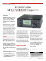
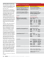
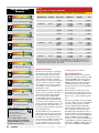
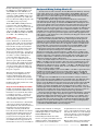
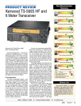
i9100
HF/VHF/UHF Transceiver
QST Product Review
QST Magazine is owned and published by
the American Radio Relay League (ARRL).
Icom America expresses its gratitude to the ARRL for the
permission to reprint and post this review on our Website.
This product review remains the copyright of the ARRL.
To join the ARRL, please visit www.arrl.org
©2012 Icom America Inc. The Icom logo is a registered trademark of Icom Inc.
TechnicalReview
Product
by Mark
Spencer,
WA8SME
Mark
J. Wilson,
K1RO,
[email protected]
ICOM IC-9100
MF/HF/VHF/UHF Transceiver
ICOM’s new dc to daylight transceiver raises the bar.
Reviewed by Rick Lindquist, WW3DE
National Contest Journal Managing Editor
[email protected]
The only real problem I encountered with the
ICOM IC-9100 was getting it away from the
delivery guy, a budding ham. He was taken
by what was on the outside of the ICOM
packing box. Users, however, have been
impressed by what’s inside the box of this
solid-performing dc-to-daylight, all-in-one
transceiver.
The IC-9100 is essentially the “plus” version
of the IC-7410 reviewed in October 2011,
and it shares many traits with that radio
vis-à-vis its HF and 50 MHz capabilities,
which we won’t reiterate here in detail.1 But
it’s not quite that straightforward. With the
IC-9100’s substantially higher price tag come
the IC-7410’s HF and 6 meter performance
plus all-mode VHF, UHF and satellite
features and capabilities. Think of it as a
shack in a box. Is the IC-9100 a good value
and match for your operating style and
preferences — not to mention your budget?
We’ll report. You decide. Let’s take a look.
Genealogy
We’re tempted to think of the IC-7410 and
IC-9100 solely as descendants of ICOM’s
venerable IC-746/756 platform (with a bit of
IC-706 DNA thrown in for good measure).
But, the ’9100’s nomenclature also recalls
ICOM’s noteworthy VHF-UHF three-band
all-mode transceiver of a decade ago, the
IC-910H. It comes as no surprise that the
IC-9100 has retained the best features of its
older sibling. ICOM and other manufacturers
offer several all-mode transceivers that cover
from HF through 440 MHz. The IC-9100,
however, is only one of two currently available desktop radios that include an option for
1.2 GHz.
Fish or Fowl?
ICOM has done a creditable job of balancing
the IC-9100’s HF+50 MHz performance with
1R. Lindquist,
N1RL, “ICOM IC-7410 HF and
6 Meter Transceiver,” Product Review, QST,
Oct 2011, pp 49-54. This review and reviews of
the other ICOM transceivers mentioned here
are available to ARRL members online at
www.arrl.org/product-review.
its expanded VHF and UHF coverage and
capabilities. The bare-bones IC-9100 is a
full-featured 100 W transceiver for HF,
6 meters, 2 meters and provides 75 W on
70 cm, with all the goodies you’d expect for
FM simplex and repeater operation plus
satellite work. With our IC-9100 we ordered
the optional UX-9100 23 cm module (10 W),
UT-121 D-DSTAR module, optional narrow
1st IF (“roofing”) filters for HF and 50 MHz
and the RS-BA1 IP Remote Control Software
package that permits remote control via the
Internet or other IP network (more on this
later). Add a power supply and antennas, and
you’re ready to cover considerable Amateur
Radio real estate in relative style — without
even having to be in your shack!
Doubling and Tripling Down
Packing these expanded capabilities into a
box that’s very similar to the IC-7410’s and
that has a nearly identical front panel requires
many dual-purpose (or multi-purpose)
buttons and controls. The labels are the same,
nicely contrasting white-on-black style as the
’7410’s and easy to read, once you’ve deciphered the abbreviations dictated by space
restrictions. Legends for some second and
third-tier functions can be harder to make
out. Good shack lighting helps considerably.
The ’9100’s broader and more-complex
range of functions, especially those reserved
for satellite work, means a steeper learning
curve. The IC-9100 diverges from the
IC-7410 in several significant ways, starting
with the front panel, where there’s been a bit
of musical chairs between models. The ’9100
features two independent receivers and can
receive on two bands at the same time —
although not on two HF bands.
There’s a single MAIN DIAL for tuning, but the
main and sub receivers do have separate (and
concentric) AF GAIN and SQUELCH controls.
With a stereo headset (or separate speakers)
you can listen to both receivers at the same
time, one in each ear. To do things such as
operating split on HF means setting up VFO A
and VFO B to the appropriate frequencies
(you can designate a default split — say,
2 kHz — via the menu). The split function is
independent from the repeater split function,
also set via the menu.
The ’9100 includes a DV/DR button (for digital
voice/digital repeater operation) among the
Bottom Line
Compact and versatile, the IC-9100
handles almost any type of operating
on the 160 meter through 2 meter
bands, plus 70 and 23 cm.
QST – Devoted Entirely to Amateur Radio
www.arrl.org
April 2012 51
mode buttons, which are bracketed by the
MENU and FILTER buttons. Given the addition
of the DV/DR button, the ’9100 does not have
separate CW and RTTY mode buttons as on the
’7410. There is a single CW/RTTY key. There
are other accommodations. Take notes!
There will be a quiz.
Since the main receiver’s AF/RF SQUELCH
controls take up the spot where the MIC and
RF PWR controls live on the ’7410, ICOM has
relegated these functions to the row of four
stem controls along the lower apron of the
front panel. The ’9100’s stem controls are
sturdier than the ones on, say, the
IC-756PROIII, but it’s difficult to determine
their relative settings. The other two stem
controls are for CW PITCH and KEY SPEED. A
dab of white paint on the tiny arrow of each
stem would help. The ’9100’s NOTCH control
has migrated to the lefthand side of the panel
to assume the outer ring position of the NR/
NOTCH control, which, in turn, is directly
above the main receiver’s AF/RF SQUELCH
controls.
Topping the column of buttons immediately
to the right of the display window is the
SATELLITE mode button, followed by the
MAIN/SUB (band) selection and SUB buttons.
The SPLIT, A/B and XFC buttons are on the
bottom. A NOR/REV function for inverting
satellite up and downlinks is a secondary
function of the 7/[3] band/keypad button.
Complementing the PBT CLR (passband
tuning clear) button on the right hand side of
the panel is the SUB DIAL button. Its function
is too difficult to explain in a few words and
without the table in the Instruction Manual,
which didn’t do a very good job of explaining
it anyway; the manual says that it enables
tuning, mode selection, memory selection
and programming for the sub band receiver.
The SUB DIAL button is not to be confused
with the MAIN/SUB and SUB buttons or with
the MAIN and SUB secondary-function buttons.
Concentric rotary controls on the right hand
side of the panel — where the NOTCH/CW
PITCH controls are on the ’7410 — enable
selection of memory channels for the main
and sub band receivers. There are no physical
buttons or controls for enabling and adjusting
the speech compressor; these are menu
functions. The row of buttons to the immediate right of the stem controls include P.AMP/
ATT, NB, VOX/BK-IN, MONITOR and CALL/GPS.
GPS? With an NMEA compatible, thirdparty GPS receiver connected to the transceiver’s DATA jack, you can display, transmit,
receive and store GPS/GPS-A data. The
Instruction Manual devotes 16 pages to this
topic.
Table 1
ICOM IC-9100, serial number 02001053
Manufacturer’s Specifications
Measured in the ARRL Lab
Frequency coverage: Receive, 0.03-60, 136-174, Receive, as specified; transmit, as
420-480, 1240-1320 MHz; transmit, 1.8-2.0,
specified, except 5.255-5.405 MHz,
3.5-4, 5.3305, 5.3465, 5.3665, 5.3715,
non channelized. The optional UX-9100
5.4035, 7-7.3, 10.1-10.15, 14-14.35, 18.068-
is required for 23 cm operation.
18.168, 21-21.45, 24.89-24.99, 28-29.7,
50-54, 144-148, 430-450, 1240-1300 MHz.
Power requirement: 13.8 ±15% V dc; receive, 4.5 A (max audio, HF, 50, 144, 430 MHz),
5.5 A (max audio, 1200 MHz); transmit, 24 A
(HF, 50, 144, 430 MHz), 9 A (1200 MHz).
13.8 V dc; receive 3.2 A (no signal, max
audio), 3 A (no signal, max audio,
backlight off); transmit, 19.7 A (HF, 144,
430 MHz), 8.4 A (1296 MHz); 54 mA
(transceiver off). Operation confirmed
at 11.4 V dc (89 W output, HF).
Modes of operation: SSB, CW, AM, FM, RTTY, DV.
As specified. The optional UT-121 is
required for DV operation.
Receiver
SSB/CW sensitivity: 2.4 kHz bandwidth, 10 dB S/N: 0.1-29.99 MHz, 0.16 µV; 50-54 MHz, 0.13 µV, 144/430/1200 MHz,
0.11 µV.
Receiver Dynamic Testing
Noise floor (MDS), 500 Hz filter,
3 kHz roofing filter:
Preamp Off
1
2
0.137 MHz –122 –131 –135 dBm
0.505 MHz –134 –140 –142 dBm
1.0 MHz
–133 –140 –142 dBm
3.5 MHz
–134 –142 –144 dBm
14 MHz
–133 –141 –143 dBm
50 MHz
–130 –140 –142 dBm
144 MHz
—
—
–143 dBm
430 MHz
—
—
–144 dBm
1296 MHz —
—
–145 dBm
Noise figure: Not specified.
Preamp off/1/2: 14 MHz, 13/6/4 dB;
50 MHz, 17/7/5 dB, 144 MHz, 4 dB;
430 MHz, 3 dB; 1296 MHz, 2 dB.
AM sensitivity: 6 kHz bandwidth, 10 dB S/N:
0.5-1.799 MHz, 12.6 µV; 1.8-30 MHz, 2 µV;
50-54 MHz, 1.6 µV; 144/430 MHz, 1.4 µV.
10 dB (S+N)/N, 1 kHz tone, 30%
modulation, 6 kHz bandwidth:
Preamp
Off
1
2
1.0 MHz
1.68 0.72 0.65 µV
3.8 MHz
1.46 0.62 0.56 µV
50.4 MHz
2.51 0.92
0.75 µV
144 MHz
—
—
0.57 µV
430 MHz
—
—
0.55 µV
FM sensitivity: 15 kHz bandwidth, 12 dB SINAD: 28-29.7 MHz, 0.5 µV; 50-54 MHz, 0.32 µV;
144/430/1200 MHz, 0.18 µV
For 12 dB SINAD, 3 kHz deviation,
15 kHz bandwidth:
Preamp
Off
1
2
29 MHz
0.56 0.21 0.17 µV
52 MHz
0.70 0.20
0.20 µV
146 MHz
—
—
0.17 µV
440 MHz
—
—
0.17 µV
1290 MHz —
—
0.15 µV
Spectral display sensitivity: Not specified.
Preamp off/1/2, –94/–101/–110 dBm.†
Blocking gain compression dynamic range:
Blocking gain compression dynamic range,
Not specified.
500 Hz bandwidth, 3 kHz roofing filter:
20 kHz offset
5/2 kHz offset
Preamp off/1/2 Preamp off
3.5 MHz 141/139/138 dB 121/111 dB
14 MHz
142/140/134 dB 120/111 dB
50 MHz
139/141/136 dB 119/110 dB
Preamp 2
Preamp 2
144 MHz 130 dB
111/110 dB
430 MHz 119 dB
109/103 dB
1296 MHz 100 dB
95/89 dB
Reciprocal mixing dynamic range:
Not specified.
Reciprocal mixing dynamic range,
500 Hz bandwidth, 3 kHz roofing filter:
14 MHz, 20/5/2 kHz offset: 101/80/77 dB.
ARRL Lab Two-Tone IMD Testing
See Table 2.
Second-order intercept point: Not specified.
Preamp off/1/2, 14 MHz, +65/+65/+65 dBm;
50 MHz, +73/+73/+73 dBm; preamp 2,
144 MHz, +69 dBm; 430 MHz, +90 dBm.
FM adjacent channel rejection: Not specified.
Preamp 2: 29 MHz, 81 dB; 52 MHz, 78 dB;
146 MHz, 77 dB; 440 MHz, 66 dB;
1290 MHz, 68 dB.
Okay, got it? And we haven’t even discussed
the display!
52 April 2012
ARRL – the national association for Amateur Radio
www.arrl.org Table 1
ICOM IC-9100, serial number 02001053 [continued]
FM two-tone, third-order IMD dynamic range:
Not specified.
DSP noise reduction: Not specified.
Notch filter depth: Not specified.
S-meter sensitivity: Not specified.
Squelch sensitivity: SSB (HF/50 MHz), <5.6 µV, FM (HF/50 MHz), <0.3 µV; SSB (144/430/ 1200 MHz), <1.0 µV, FM (144/430/1200 MHz),
<0.18 µV.
Receiver audio output: >2 W into 8 W at
10% THD.
IF/audio response: Not specified.
Spurious and image rejection: HF and 50 MHz, (except IF rejection on 50 MHz): >70 dB;
144/430 MHz, >60 dB; 1200 MHz, >50 dB
20 kHz offset, preamp 2: 29 MHz, 81 dB*;
52 MHz, 78 dB*; 146 dB, 77 dB*;
440 MHz, 66 dB*, 1290 MHz, 68 dB*.
10 MHz channel spacing: 29 MHz, 115 dB;
52 MHz, 113 dB; 146 MHz, 97 dB;
440 MHz, 82 dB; 1290 MHz, 70 dB.
Variable, 18 dB maximum.
Manual notch: 61 dB, auto notch: 53 dB,
attack time: 40 ms.**
S9 signal at 14.2 MHz: preamp off/1/2,
62.3/26.3/9.9 µV; 50 MHz, 80.3/31.2/
12.3 µV; preamp 2, 144 MHz, 3.35 µV;
430 MHz, 3.16 µV; 1296 MHz, 3.05 µV.
At threshold, preamps on: SSB, HF, 0.8 µV;
50 MHz, 1.0 µV; 144 MHz 0.39 µV;
430 MHz, 0.46 µV; 1296 MHz, 0.39 µV;
FM, 29, 50 and 440 MHz, 0.1 µV,
146 MHz, 0.09 µV; 1290 MHz, 0.05 µV.
2.14 W at 10% THD into 8 W.
THD at 1 V RMS, 0.85%.
Range at –6 dB points, (bandwidth):**
CW (500 Hz): 340-820 Hz (480 Hz);
Equivalent Rectangular BW: 504 Hz;
USB: (2.4 kHz): 360-2614 Hz (2254 Hz);
LSB: (2.4 kHz): 360-2618 Hz (2258 Hz);
AM: (6 kHz): 175-3152 Hz (5954 Hz);
AM: (9 kHz): 175-3875 Hz (7400 Hz).
First IF rejection, 14 MHz, 103 dB;
50 MHz, 105 dB*; 144 MHz, 143 dB;
430 MHz, 137 dB*; 1296 MHz, 127 dB*.
Image rejection, 14 MHz, >121 dB;
50 MHz, > 110 dB;144 MHz, 75 dB;
430 MHz, 89 dB; 1296 MHz, 104 dB.
Transmitter
Transmitter Dynamic Testing
Power output: HF & 50 MHz: SSB, CW, RTTY, HF: CW, SSB, RTTY, FM, typically
FM, 2-100 W; AM, 2-30 W; 144 MHz, 2- 1.8-102 W, AM, 0.25-27 W; 50 MHz:
100 W; 430 MHz, 2-75 W; 1200 MHz, 1-10 W.
CW, SSB, RTTY, FM, 1.7-95 W,
AM, 0.25-25 W; 144 MHz, 1.5-98 W;
430 MHz, 1.4-71 W; 1296 MHz, 0.5-9.3 W.
Spurious-signal and harmonic suppression:
HF, 68 dB (20 m), typically >70 dB;
>50 dB (HF), > 63 dB (50/144 MHz);
50/144/430/1296 MHz, >70 dB.
>61.8 dB (430 MHz); >53 dB (1200 MHz).
Meets FCC requirements.
SSB carrier suppression: > 40 dB.
HF/144/430/1296 MHz, >70 dB;
50 MHz, 68 dB.
Undesired sideband suppression: >55 dB.
>70 dB.
Third-order intermodulation distortion (IMD)
3rd/5th/7th/9th order (20 m, worst case):
products: Not specified. (dB)
HF, 100W PEP, –29/–36/–50/–64;
50 MHz, 100 W PEP, –29/–34/–43/–54;
144 MHz, 100 W PEP, –26/–37/–43/–54;
430 MHz, 75 W PEP, –24/–37/–45/–53;
1296 MHz, 10 W PEP, –37/–53/–55/–58.
CW keyer speed range: Not specified.
6.1 to 46.7 WPM. Iambic keyer Mode B.
CW keying characteristics: Not specified.
See Figures 1 and 2.
Transmit-receive turnaround time (PTT release
S9 signal, 87 ms at speaker,
to 50% audio output): Not specified.
18 ms at accessory jack.
Receive-transmit turnaround time (tx delay):
SSB, 61 ms; FM, 12 ms.
Not specified.
Composite transmitted noise: Not specified.
See Figure 3.
Size (height, width, depth): 4.6 × 12.4 × 13.5 inches; weight, 24.2 pounds.
Price: IC-9100, $3600; UX-9100 23 cm module, $700; UT-121 DV adapter, $230; RS-BA1
remote control software, $100; FL-430 (6 kHz), FL-431 (3 kHz) roofing filters, $125 each.
†Simple
band scope; receiver is muted during scanning.
*Measurement was noise-limited at the value indicated.
**Single beat note. Reduces two beat notes up to 40 dB with attack time depending on separation of signals,
typically 500 ms.
***Default values, sharp setting (smooth setting is available). Bandwidth and cutoff frequency
are adjustable via DSP. CW bandwidth varies with PBT and pitch control settings.
0
0.01 0.02 0.03 0.04 0.05 0.06 0.07 0.08
Time (s)
Figure 1 — CW keying waveform for the
IC-9100 showing the first two dits in full break-in
(QSK) mode using external keying. Equivalent
keying speed is 60 WPM. The upper trace is
the actual key closure; the lower trace is the RF
envelope. (Note that the first key closure starts at
the left edge of the figure.) Horizontal divisions
are 10 ms. The transceiver was being operated
at 100 W output on the 14 MHz band.
QS1204-ProdRev02
Reponse, dB
Measured in the ARRL Lab
fc-4
fc+2
fc
Frequency in kHz
fc-2
fc+4
Figure 2 — Spectral display of the IC-9100 transmitter during keying sideband testing. Equivalent
keying speed is 60 WPM using external keying.
Spectrum analyzer resolution bandwidth is
10 Hz, and the sweep time is 30 seconds. The
transmitter was being operated at 100 W PEP
output on the 14 MHz band, and this plot shows
the transmitter output ±5 kHz from the carrier. The
reference level is 0 dBc, and the vertical scale is
in dB. Note that the keying sideband level rises
slightly at the edges, to the –65 dB range.
QS1204-Prodrev03
0
-20
-40
Response in dB
Manufacturer’s Specifications
QS1204-ProdRev01
-60
-80
-100
-120
-140
-160
-180
1x10 2
1x10 3
1x10 4
1x10 5
Frequency in Hz
1x10 6
Figure 3 — Spectral display of the IC-9100
transmitter output during composite noise testing.
Power output is 100 W on the 14 MHz band. The
carrier, off the left edge of the plot, is not shown.
This plot shows composite transmitted noise
100 Hz to 1 MHz from the carrier. The reference
level is 0 dBc, and the vertical scale is in dB.
QST – Devoted Entirely to Amateur Radio
www.arrl.org
April 2012 53
Table 2
ICOM IC-9100, serial number 02001053
Key Measurements
Summary
ARRL Lab Two-Tone IMD Testing (500 Hz DSP bandwidth, 3 kHz roofing filter)‡
Band/Preamp Spacing Input Level
Measured
IMD Level
Measured
IMD DR
Calculated
IP3
3.5 MHz/Off
20 kHz
–26 dBm
–13 dBm
–134 dBm
108 dB
–97 dBm
+28 dBm
+29 dBm
14 MHz/Off
20 kHz
–25 dBm
–13 dBm
0 dBm
–133 dBm
108 dB
–97 dBm
–63 dBm
+29 dBm
+29 dBm
+32 dBm
14 MHz/1
20 kHz
–35 dBm
–20 dBm
–141 dBm
106 dB
–97 dBm
+18 dBm
+19 dBm
108
14 MHz/2
20 kHz
–42 dBm
–27 dBm
–143 dBm
101 dB
–97 dBm
+9 dBm
+8 dBm
108 110
14 MHz/Off
5 kHz
–37 dBm
–26 dBm
0 dBm
–133 dBm
96 dB
–97 dBm
–23 dBm
+11 dBm
+10 dBm
+12 dBm
14 MHz/Off
2 kHz
–46 dBm
–31 dBm
0 dBm
–133 dBm
87 dB
–97 dBm
–18 dBm
–2 dBm
+2 dBm
+9 dBm
50 MHz/Off
20 kHz
–20 dBm
–13 dBm
–130 dBm
110 dB
–97 dBm
+35 dBm
+29 dBm
144 MHz/2
20 kHz
–47 dBm
–34 dBm
–143 dBm
96 dB
–97 dBm
+1 dBm
–2 dBm
430 MHz/2
20 kHz
–50 dBm
–36 dBm
–144 dBm
94 dB
–97 dBm
–3 dBm
–5 dBm
50
101
20 60
140
20 kHz Reciprocal Mixing Dynamic Range
141*
%*
142*
20 70
140
20 kHz Blocking Gain Compression (dB)
,
20 50
20 kHz 3rd-Order Dynamic Range (dB)
50
60
2
77
140
2 kHz Reciprocal Mixing Dynamic Range
111
%*
111
70
2
140
2 kHz Blocking Gain Compression (dB)
,
87
50
2
‡ARRL
Product Review testing now includes Two-Tone IMD results at several signal levels. on the first
line in each group. The “IP3” column is the calculated third-order intercept point. Intercept points were
determined using –97 dBm reference. Receiver IMD not measured at 1296 MHz due to lack of third
signal generator capable of operation above 1 GHz.
110
2 kHz 3rd-Order Dynamic Range (dB)
29
,
29 +35
20 -40
20 kHz 3rd-Order Intercept (dBm)
,
2
2
-40
+30
2 kHz 3rd-Order Intercept (dBm)
,
TX -20
-29
Transmit 3rd-Order IMD (dB)
-35
,
TX -20
-64
-70
Transmit 9th-order IMD (dB)
pr067
Key:
* Off Scale
80 M
Dynamic range and intercept
values with preamp off.
Intercept values were determined
using -97 dBm reference
20 M
See the digital edition and the
QST-in-Depth website (www.arrl.
org/qst-in-depth) for the VHF/UHF
measurements summary.
54 April 2012
Window on the World
The main receiver’s frequency and settings
appear in the top half of the commodious
monochrome display, the sub receiver’s
frequency and settings in the bottom half.
Only one-half of the display can handle
transmit frequency readout and settings. The
receivers’ frequency readouts are sizeable
and extremely easy to see from across the
room. Display contrast and brightness are
adjustable via a menu.
something appeared or vanished.
I found it difficult to read the rather light “dot
matrix” type text presented in the menu area
along the bottom of the display. Its limitations were especially noticeable while
decoding RTTY signals using the built-in
decoder. Selecting the desired first IF filter
via this menu can be a bit tricky, too, as this
involves pressing and holding a button to step
through the choices. These filters sure are
nice to have, though; I’d suggest setting these
up to defaults by mode.
While sensitivity is an important receiver
performance metric, all of today’s amateur
transceivers hear well. This shifts the focus to
dynamic range as a more significant parameter.
Since IC-9100 users are more likely to be
using the main and sub receivers in tandem,
the tiny (but clearer and darker) legends on
the display screen may be hard to see. In
some cases, these too-subtle readouts provide
the only means of knowing a particular
feature is enabled. In a few cases I had to
toggle the feature on and off, to see where
ARRL – the national association for Amateur Radio
Let’s Do the Numbers!
The IC-9100 delivers the same competent
performance we experienced with the ’7410
on HF and 50 MHz and more than merely
commendable performance on VHF and
UHF. It is that latter capability that anyone
considering the purchase of an IC-9100
should care about; if not, the IC-7410 might
be a better option.
Dynamic range numbers, in general, quantify
a receiver’s ability to perceive weak signals in
the vicinity of strong signals (see sidebar,
“Reciprocal Mixing Testing: What Is It?”
which explains the subtleties of the various
shades of dynamic range). How does the
IC-9100 stack up in those higher reaches of
the Amateur Radio spectrum? Quite well, as
it turns out. A two tone, third order IMD DR
number of 100 dB or greater (at 20 kHz
spacing) once was considered the hallmark of
a quality HF receiver. The IC-9100 tops that
benchmark at 50 MHz by 10 dB and it comes
pretty close at 144 MHz and at 430 MHz.
www.arrl.org In terms of blocking gain compression, the
IC-9100 turns in excellent numbers on 144
and 430 MHz, more than 100 dB even at
2 kHz spacing. It’s a bit lower on 23 cm. For
comparison, on HF (14 MHz), where you’d
expect better performance, the ’9100 comes
in at 142, 120 and 111 dB (preamp off) at 20,
5 and 2 kHz spacings, respectively.
The IC-9100’s VHF and UHF performance
is superior to that of the IC-910H. To see
how far we’ve come over the past decade, the
IC-910H’s two tone, third order IMD DR
came in at 85 dB (noise limited) at 144 MHz,
80 dB at 432 MHz and 78 dB (noise limited)
at 1.2 GHz — all at 20 kHz spacing.
To ALC or Not
In the wake of a report or two we’d overheard on the Internet, we checked for ALC
overshoot. This would cause the transmitter’s
output power to max out for a split second
before the ALC circuitry reins it in. Here’s
what we found: At various barefoot exciter
power levels, we observed no overshoot
whatsoever in the CW mode — the mode we
use in testing for power spikes. In SSB mode,
we found no overshoot at full output. At
power levels below 50 W and with the
speech compressor enabled, however, we
observed a power spike on the first syllable
of the word hello. We carefully observed the
ALC readout while transmitting, keeping it
at about two thirds of full scale. There was
no apparent power spike if we switched off
the speech compressor.
This particular issue might be a problem
when using certain amplifiers. If so, we
would recommend turning off the speech
compressor; this would also keep the linear
amplifier output within the legal power limit.
ICOM was still looking into this issue as this
review went to press.
Okay, Now for the Really Cool Stuff
ICOM’s optional RS-BA1 software makes it
possible to operate the IC-9100 remotely via
the Internet or a local network. The software
is actually two programs — a remote connection utility and a virtual front panel to
control the radio. I had somewhat mixed but
overall gratifying results using it.
Your “server” PC must have a direct Internet
connection; for me this meant snaking an
extra long Ethernet cable down the stairs and
through the house. To load the software,
you’ll need to enter the product ID and
license key from the CD label. Our software
CD, labeled “Programming Software Icom
Cloning System,” came with the original
program version and an upgrade. The software does not come with a hard copy manual. A PDF manual was supposed to be on
the CD, but it was not, nor was it available on
Reciprocal Mixing Testing: What Is It?
You may notice two new color bars in the “Key Measurements Summary” at the top
of this review. These are for reciprocal mixing dynamic range (RMDR), with measurements at 20 and 2 kHz spacing. We’ve reported reciprocal mixing since December
2007, but it’s easy to overlook these figures in the table. From this review forward, we
will include RMDR in the Key Measurements Summary.
We report three dynamic range measurements that determine a transceiver’s
overall performance. Along with blocking gain compression dynamic range and two
tone third order dynamic range, we must consider RMDR while evaluating how well a
receiver hears. Which of these measurements is the most important factor in comparing receivers depends a lot on how you plan to use that receiver. For hearing weak
signals at or near the receiver’s noise floor, receiver noise typically is the limiting factor.
For the reception of stronger signals under crowded band conditions, two tone third
order DR is the most important number. To assess a receiver’s ability to perform well in
the presence of a single, strong off-channel signal (common within geographical ham
radio “clusters” or with another ham on the same block), blocking gain compression DR
is usually the dominant factor.
Reciprocal mixing is noise generated in a superheterodyne receiver when noise
from the local oscillator (LO) mixes with strong, adjacent signals. All LOs generate
some noise on each sideband, and some LOs produce more noise than others. This
sideband noise mixes with the strong, adjacent off-channel signal, and this generates
noise at the output of the mixer. This noise can degrade a receiver’s sensitivity and is
most notable when a strong signal is just outside the IF passband. RMDR at 2 kHz
spacing is almost always the worst of the dynamic range measurements at 2 kHz
spacing that we report in the “Product Review” data table.
We perform the reciprocal mixing test at 14.025 MHz, using a very low noise
Wenzel test oscillator with a measured output of +14 dBm. The test oscillator’s sideband noise is considerably below the reciprocal mixing we’re measuring. We feed the
oscillator’s output into a step attenuator, which we adjust until an audio meter on the
receiver’s output indicates a 3 dB increase in background noise. The RMDR is the
output level at which we note this 3 dB increase.
Here’s an example: Suppose the receiver’s noise floor (minimum discernable signal,
MDS) is –133 dBm, and a strong station 2 kHz away causes a 3 dB increase in noise
at a level of –53 dBm into the receiver’s antenna jack. The reciprocal mixing figure is
MDS minus the 3 dB increase level: –133 dBm – (–53 dBm) = –80 dBm. We previously
would have reported this as –80 dBc. Since we now consider this as a dynamic range
number, we report it simply as 80 dB.
In our real-world example, if your receiver’s MDS is –133 dBm, a signal 2 kHz away
at 20 dB over S-9 will cause the noise in the audio output to increase by 3 dB. This
reduces your receiver’s MDS by that amount, resulting in an MDS of –130 dBm. A
stronger signal will create more noise, but our benchmark for testing is a 3 dB increase
in noise.
The upper end of the RMDR bar on the key measurements summary charts has
been set just above the highest RMDR seen in the ARRL Lab to date. SDR and analog
type receivers have different performance characteristics and design tradeoffs. For
instance, some I/Q SDRs have been observed to have rather mediocre third order IMD
dynamic range when tested in a laboratory environment with just two signals, but if
hooked to an antenna with multiple signals simulating real band conditions, have considerably higher third order IMD dynamic range. RMDR, on the other hand, can be lower
under the same conditions than what is observed in the Lab. If choosing a receiver for
real world use, it’s important to consider all three dynamic range parameters.
Note how reciprocal mixing relates to the two-tone third order DR figures, especially
at 5 and 2 kHz spacing. A single, strong adjacent signal 5 or 2 kHz from the desired
signal with resulting reciprocal mixing has a greater impact on a your ability to hear a
desired weak signal than do two strong signals 5 and 10 kHz away (5 kHz spacing)
or 2 and 4 kHz away (2 kHz spacing) with a resulting intermodulation distortion (IMD)
product that covers up the desired signal. In many cases, reciprocal mixing dynamic
range is the primary limiting factor of a receiver’s performance.
— Bob Allison, WB1GCM, ARRL Laboratory Engineer
ICOM’s website. I found it on a third-party
website, www.ab4oj.com. ICOM does offer
a RS-BA1 Quick Reference Guide online at
www.icomamerica.com.
Understanding the instructions in either
resource can require good intuition and even
outright speculation, and the English in the
software itself was occasionally hard to
decipher. What I saw on my screen did not
always comport with the instructions. All of
this aside, the software does work, although
setting everything up can be rather demanding and requires some degree of computer
and networking savvy.
Help is at hand, however. After running into
a brick wall on connecting to the remote
QST – Devoted Entirely to Amateur Radio
www.arrl.org
April 2012 55
Into the Great Beyond: VHF/UHF and Satellite Operation
Prior to lab testing the IC-9100,
I installed the UX-9100 23 cm band
unit. The electronics are concealed in
a die cast metal box, with few connections necessary, but you must follow
the single page of instructions closely.
Installation took about 40 minutes and
went smoothly.
We also added the UT-121 module
for digital voice (D-STAR) operation. It’s
a 13⁄4 inch double sided circuit board with
a tiny, multi-pin connector that plugs in
directly behind the radio’s front panel.
This entails removing both covers and
tilting the front panel. Double-sided tape
secures the UT-121. The instructions
were easy to follow, but have a magnifying glass handy to ensure the plugs are
properly seated. Installation took about
20 minutes, and I confirmed proper
operation by contacting the W1HQ
D-STAR repeater at the ARRL Lab.
ARRL Roanoke Division Vice
Director Jim Boehner, N2ZZ, mentioned
that after he installed the UT-121 in
his new IC-9100, the radio locked
on transmit whenever he made a DV
transmission. A few other users have
reported this issue as well. “I reseated
the module several times to no avail,”
he told us. “What did work, though, was
slightly rotating the module clockwise
and counterclockwise about a degree or
so after insertion. I guess this allowed
the contacts to finally seat properly.”
Satellite Operation
Since VHF/UHF lab results overall
were quite good, I was curious to try
the IC-9100 using the satellite mode.
So, it was off to W1AW where station
manager Joe Carcia, NJ1Q, hooked
up the satellite tracking antenna.
Rotator control was via Orbitron
software, which also provided a
Doppler-corrected frequency readout
of the uplink and downlink frequencies of available satellites. If you’re
relatively new to satellite operation (as
I am), you’ll soon realize the need to
do some homework before attempting contacts. I picked the AO-27 FM
“Easy Sat.”
As a first time satellite operator, I
naively pushed the SATELLITE button
and hoped for the best. Most who have
operated through satellites will not be
surprised that after aimlessly pressing
other buttons I had to go to the well
written manual.
With a bit of practice, I determined
how to enter satellite mode and dial
in a satellite’s uplink and downlink
frequencies. The ’9100 has 20 satellite
memory channels. I simply used VFO
mode, which is pretty slick. The uplink
and downlink frequencies track each
other, and you can reverse the direction
in one VFO for inverting satellites (as
well as invert sidebands as necessary).
As AO-27 passed above the horizon, I simply tuned for best reception
while matching the predicted Doppler
adjusted frequency that Orbitron displayed. To ensure you’re not running
too much power (doing so can sap
the satellite’s power resources) you
can perform a loop test. This is done
by noting the satellite beacon’s signal
strength and then listening to yourself
on the downlink. Your downlink signal
should always be weaker than that of
the beacon. I found that just 2 or 3 W
did the trick.
During the next pass I made two
contacts. Many were waiting to do the
same, so I kept each contact brief.
I greatly appreciated the ease with
which the ’9100 makes satellite contacts possible. The sensitivity on each
’7800, and even some older ICOMs, such as
the ’PROIII. It is not possible to access all of
the radio’s functions remotely — most
notably in the case of the ’9100, the satellite
mode — and only one VFO is available,
although split operation is still possible. You
cannot change filter settings or adjust noise
reduction or noise blanker levels. The screen
offers full metering capabilities, including an
S-meter. Among other limitations, while you
can access the radio’s four CW memories,
there is no way to adjust the CW keyer speed
from the remote PC, and there’s no VOX for
phone operation. A loud and increasingly
annoying beep accompanies every mouse
action on the control screen. This includes
tuning up and down, done via the right and
left mouse buttons, respectively.
Figure 4 — The RS-BA1 control screen.
server, I got excellent advice and assistance
from the Yahoo! RS-BA1 users’ group,
especially from Herb Schoenbohm, KV4FZ,
who is extremely knowledgeable regarding
the ins and outs of networking in general and
this software in particular.
56 April 2012
I was able to connect to the IC-9100 via my
wireless LAN and control it from my den
using a laptop. The virtual front panel
(Figure 4) is smallish and generic, since the
RS-BA1 software works with other ICOM
radios, including the IC-7600, ’7700 and
ARRL – the national association for Amateur Radio
Operating CW involves inputting text from
the keyboard, which either goes into a buffer
or can be sent immediately (there’s no way to
connect a key or paddle). This takes getting
used to, but I was able to work stations after
a fashion. Operating phone was another
matter, and I never really was able to get
clear, untroubled audio from the remote PC
to the transceiver. When connected via the
remote laptop, considerable hiss and hash
threatened to overwhelm the spoken word
completely. Connecting “locally” at the
www.arrl.org band is excellent, which helps pull out
the weak-ish signals emanating from
low powered satellites.
Terrestrial V/UHF Operation
The ARRL January VHF
Sweepstakes offered another opportunity to put the ’9100 to the test. My
own all band transceiver does all
right with the help of external preamps, although at times it’s prone to
overload and other unwanted effects
from several local strong stations,
especially on 2 meter SSB.
I normally run a 150 W brick amplifier on 2 meters, but the ’9100’s 100 W
out represented only about a 1.8 dB
gain reduction. On the other hand the
nearly 75 W output on 432 MHz was
an improvement over my usual 20 W,
yielding a 5.7 dB boost. A temporary
14 element loop Yagi served as my very
first 23 cm antenna for SSB operation, providing a calculated 100 W ERP.
My high hopes of beating my own
previous best score were dashed
somewhat, as the very cold weather
made my rotators sluggish or freeze
up altogether. I got a good idea of
strong adjacent signal receive perfor-
server PC in the shack greatly attenuated, but
did not eliminate, this noise. Some users
have complained about “hiss” in their audio,
and this may be what I heard.
The most fun I had with the RS-BA1 software
was connecting to another radio amateur’s
IC-7410 in another part of the world. While
there was a fair amount of latency (delay) on
the connection, I was able to hear my own
station’s signal on 160 meters, which offered
an opportunity to check different antennas
and power levels. All told, this ICOM package can and does work, although there are
more elegant solutions to remotely controlling your station — some of them free.
Miscellany
The IC-9100 includes provisions for using
VHF/UHF mast mounted preamps. The
manual points out that ICOM AG-25, AG-35
or AG-1200 preamplifier units are compatible for the 2 meter, 70 cm and 23 cm bands,
respectively. If you want to use one of these
OEM preamps, however, you’ll have to find
it on the used market. As a footnote points
out, they’ve been discontinued. The menu
includes an EXT-P.AMP selection for each
affected band.
A potentially ear saving touch: The IC-9100
has a CW sidetone level limit in the menu, so
mance when big gun and fellow HQ
staffer Dave Patton, NN1N, aimed his
6 meter array at me, with a booming
40 dB over S9 signal. I listened carefully about 2 kHz away and found only
a small amount of reciprocal mixing
noise adding to the noise floor.
I had quite a thrill making my first
23 cm SSB contacts. The IC-9100
with the UX-9100 operated as
expected, with clear audio from the
speaker. A local contester who knows
my voice listened with a critical ear
and reported clean, smooth sounding
transmitted audio.
In Summary
Overall, I found my operating experience with the ’9100 very pleasing
and the performance superb, but I did
find one thing that would cause minor
issue in my shack. Granted, having a
separate antenna jack for each VHF/
UHF band is great for contesting
and satellite operation, but it might
hamper FM operation a bit with my
multiband 2 meter/70 cm antenna. I’d
need a diplexer to monitor both bands
at once. A minor footnote: AM mode
the sidetone does not get louder beyond a
specified level as you advance the AF control.
(I sure wish my current transceiver had this!)
The sidetone level is a separate adjustment in
the SET menu.
As with the IC-7410, you can monitor SWR
and relative power output at the same time.
The ’9100 has an LCD bar-graph style meter,
which can be set up to hold peaks for 0.5
second. The radio also retains the really slick
SWR plotting feature, letting you read and
graph your antenna system’s SWR curve,
right on the screen. This is available on all
bands except 1.2 GHz. You can plot up to
13 points in various steps. Transmit briefly to
plot the SWR on each step, and when you’re
done, the screen will graphically display the
SWR profile of the antenna system under test.
The ’9100 has an automatic frequency
control feature with settable limits. This
feature, especially useful for satellite work,
is not available above 50 MHz. Also,
seasoned VHF and UHF contesters
often pair HF transceivers with high
performance, single band transverters.
The IC-9100 does not include provisions to accommodate transverters for
222 MHz, 2304 MHz or other bands of
interest to some VHF/UHF operators.
Two things could use improvement.
First, I would like to see individual RF
output settings for each RF output port.
This would make operation “Ooops!
proof” while using external amplifiers,
each needing a specific drive level.
Operating full output at 70 cm then
switching to 2 meters without reducing
the ’9100’s RF power output control
would send 100 W into the brick amp
and damage it. Second, the optional
narrow first IF filters are not available
above 6 meters. For a more serious
contester with a lot of aluminum in
the air, having a narrow roofing filter
could make a huge difference in bands
crowded with strong signals.
All told, I would consider the
IC-9100 an ideal choice for the
single radio shack. — Bob Allison,
WB1GCM, ARRL Test Engineer
automatically compensates for a drifting
received signal.
The transceiver draws 54 mA when it’s turned
off. This may only be of concern if running
the radio from a battery power source; leaving
the transceiver hooked up to the battery will
consume 1.3 Ah per day. The Instruction
Manual recommends disconnecting the
battery from the transceiver if you don’t plan
to use it for a while.
The Verdict?
All told, the IC-9100’s multimode capability
and ample feature set get the job done, and,
if equipped for 1.2 GHz operation — on 14
MF, HF, VHF and UHF bands! Throw in the
RS-BA1 remote package, and you’re on the air
from any place you can connect to the Internet.
Manufacturer: ICOM America, 2380 116th
Ave NE, Bellevue, WA 98004; tel 800-8724266; www.icomamerica.com.
ICOM IC-9100 Video
If you own a tablet or smartphone with the appropriate application, scan this QR Code to see a video overview of the
ICOM IC-9100 transceiver. You can also watch this video
on your computer by going to (case sensitive):
http://youtu.be/tVgSFn2nV04
QST – Devoted Entirely to Amateur Radio
www.arrl.org
April 2012 57
Technical
Short Takes
by
Mark
Spencer,
WA8SME
Steve
Ford,
WB8IMY,
[email protected]
Xtal Set Society SADL
RF Attenuator Kit
Rich Arland, K7SZ
[email protected]
There are times that many of us need a step
attenuator to accurately control the output of
an RF generator during receiver alignment,
or to reduce the output of a QRP transmitter
for on-air testing. Let’s not forget the need
for a step attenuator for use in transmitter
hunting, where you need to drop the input
to your receiver to avoid overload as you
approach the hidden transmitter.
There have been many articles
detailing with how to build a step
attenuator. The current ARRL
Handbook has a construction project
on how to fabricate one of these inexpensive pieces of test gear. The obvious
hurdle to overcome is parts procurement.
Also, most of the step attenuators are not
constructed to handle more than a half
watt of input, and then only for a very short
time.
Thankfully the creative folks at the Xtal Set
Society have overcome these obstacles and
provide a nifty little kit, including a plastic
enclosure, for the paltry sum of only $49.95
plus shipping/handling. The really sweet
thing about this attenuator kit is that in
addition to a built-in dummy load with LED
indicator, it will handle a full 5 W of RF
indefinitely, making it an ideal tool for the
QRP workbench/shack. This kit can be
ordered in three configurations: complete
kit with case, kit without case and PC board
only.
Building the Kit
My QRP SADL (complete) kit arrived from
the Xtal Set Society in a small box. The PC
board was very well done with all throughhole components, which makes an easy
build for my old eyes. All components are of
high quality. Instructions are very easy to
follow and the total build time was just short
of two hours.
The build went smoothly right up until the
very last resistor, R15. The instructions and
the parts list called for a 10 kΩ 1⁄4 W resistor,
but the kit was furnished with a 1 kΩ 1⁄4 W.
A quick look at the schematic showed that
R15 was a current limiting resistor for the
LED indicator. Past experience had shown
that a 1 kΩ resistor would be okay to use in
this application so I went ahead and used the
supplied resistor for R15 with no ill effects.
After switching out the attenuator’s dummy
load I systematically proceeded to crank in
3, then 6, then 9 and finally 12 dB pads and
watched the RF on the calibrated meter. All
worked as advertised with the RF output
dropping from 5 W to 2.5, to 1.25 W, to
0.625 W and so on — just as it should.
One nice thing is the visual indicator.
It’s an LED that lights when the internal dummy load is activated and 5 W is
applied to the input port of the
attenuator. This is a great tuning
aid for the workbench.
The choice of attenuator steps is
interesting. Many attenuators are
configured to include the following
switchable pads: 3 dB, 6 dB and
several 10 dB and 20 dB pads. This
allows a wide range of attenuation.
The Xtal Set attenuator kit has a single
3 dB pad, a single 6 dB pad and two
When mounting the high-wattage resistors
12 dB pads. The 3 dB pad cuts the RF
onto the PC board the instructions called for
signal in half and is equal to 1⁄2 of an S unit.
using masking tape to hold the resistors in
A 6 dB attenuator equals 1 S unit, or a
place before turning the PC board over and
signal decrease by a factor of four. The
soldering the parts. I feel that this step is
12 dB pad equals 2 S units or a factor of 16.
unnecessary if you take the time to slightly
In other words, this attenuator makes it easy
bend the component leads away from the
to assess S meter accuracy. It also makes
hole and then solder the connections. It’s a
quick work out of figuring your QRPp
minor point, but one that speeds the build.
(power levels below 1 watt) when reducing
your transmitter output for those times you
Testing and Use
want to play the “How low can you go”
Initial testing was a breeze. The instructions
game. You can accurately attenuate your
outline a valid testing procedure, which I
5 W QRP signal all the way down to
followed. However, I
2.5 mW in 12 discrete
decided to do some
steps for a total of
All
components
are
of
additional testing. Having
high quality. Instructions 33 dB of attenuation!
a calibrated QRP wattmeter and dummy load, I are very easy to follow and Bottom line: This Xtal
Set Society SADL
the total build time was
connected the SADL kit
QRP attenuator is an
between my Elecraft K3
just short of two hours.
excellent first homeand my calibrated wattbrew/kit building
meter/dummy load and
project and provides the frugal QRPer
proceeded to apply 5 W of RF. With all the
with a very useful and interesting piece of
attenuators bypassed I observed 5 W on the
test equipment at an extremely attractive
wattmeter. I then switched in the attenuator’s
dummy load and the output meter dropped to price.
2.5 W. Essentially, both the dummy load in
Manufacturer: Xtal Set Society, PO Box 3636,
the attenuator and the dummy load on the
Lawrence, KS 66046; tel 405-517-7347;
wattmeter are in parallel and the output
www.midnightscience.com. $49.95;
should drop to half the initial output of 5 W,
kit without case, $41.95.
which is exactly what happened.
50 April 2012 ARRL – the national association for Amateur Radio www.arrl.org