1
EXIT
MENU
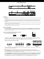
Front and Back Panel
On/Standby
Left
Front Panel Display (FPD)
Menu
Down Right
Adjustment Buttons
Up
Exit
EXIT
MENU
On/Standby
Left
Analog Video
Input
SDI Input
I
N
P
U
T
SDI
INPUT
OUTPUT
1
INPUT
2
3
4
H DM I
HDMI Output
Y (G)
O
U
T
P
U
T
HDMI Inputs
1, 2, 3, 4
Quick Note
Pb (B)
Pr (R)
H
V
Y (G)
DC In
+6V @5A
ANALOG VIDEO
Analog Video
Output
Analog Video
Input
SDI Input
Component 1
(YPbPr or RGB)
Sync 1
I 1
N
P
U
T
S 2
POWER
SYNC
Power
Sync 2
Pb (B)
Digital Audio Analog Audio
Digital
Composite Audio Out Inputs 1, 2 Inputs L, R
S-Video 1 Video 1
(optical)
(optical) (optical)
L
Pr (R)
1
1
2
2
2
COMPONENT
OUTPUT
VIDEO
Component 2
S-Video 2
(YPbPr or RGB)
Component 1
(YPbPr or RGB) S-Video 1
On/Standby
ANALOG AUDIO INPUT
INPUT
3
S-VIDEO
4
D I G I TA L A U D I O
Composite
Video 2
Composite
Video 1
R
2
1
1
Sync 1
Down Right
SERIAL PORT
Digital
Digital Audio Serial Port
Digital
Audio Out Digital
InputsAudio
3, 4 Analog Audio
1, 2 Inputs L, R
Audio
Out Inputs
(coaxial)
(coaxial)
(optical)
(optical) (optical)
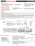
This Quick Start Guide has been created to assist you
inPbthe
first
step
of setting
up yourY (G)iScan
VP30
unit, which is accessing the iScan’s On Screen Display (OSD)
Y (G)
(B)
Pr (R)
H
V
Pb (B)
Pr (R)
on your screen.
L
I
N
P
U
T
SDI
INPUT
OUTPUT
INPUT
O
U
T
P
U
T
+6V @5A
I 1
N
P
U
T
S 2
1
1
1
OUTPUT
R
2
1
DC In
ANALOG AUDIO INPUT
INPUT
Accessing the iScan’s OSD is crucial, not only in allowing the user to navigate the menu system, but its presence lets the user know that the iScan is sending
a compatible signal to the display. If the OSD is not visible on the display’s screen by pressing one of the sub-menu buttons on the remote control, then the
Output Setup of the iScan must be configured to work with the input that is being used on the display. Following all of the steps provided should allow you to
HDMI Output
HDMI Inputs
Analog Video
Power
Sync 2
Component 2
S-Video 2 Composite Digital
Digital Audio Serial Port
see the OSD.
1, 2, 3, 4
Output
(YPbPr or RGB)
Video 2
Audio Out Inputs 3, 4
1
2
3
4
H DM I
ANALOG VIDEO
POWER
2
SYNC
2
COMPONENT
S-VIDEO
3
2
VIDEO
4
D I G I TA L A U D I O
(coaxial)
SERIAL PORT
(coaxial)
Front Panel Display (F
To best set up your iScan VP30 unit with your display, we recommend that you consult your iScan VP30 Product Guide – “Setting up an iScan Using the Internal
Test Patterns and AVIA: Guide to Home Theater Calibration DVD.”
Instruction in bold apply to specific buttons on either the front panel or remote control of the iScan VP30. Instructions in italics (top line / bottom line) apply
to information that is displayed on the Front Panel Display (FPD).
STEP 1 - Powering Up
SDI Input
Attach the removable power cord to the external power supply. Plug the removable power cord in to a wall outlet or power conditioner, if applicable.
Plug the
On/Standby
small connector attached to the cable that comes out of the power supply into your
iScan
VP30.
Press the On/Standby button on the front panel of the iScan.
Y
PB
PR
R PR/CR G Y B PB/CB H/Cs
V
Your iScan VP30 should power on and display DVDO iScan VP30 — Powered by ABT on the FPD. The Status LED on your iScan VP30 will turn red verifying
that there are no active inputs detected.
SDI
INPUT
STEP 2 - Connecting the iScan VP30 in your system
OUTPUT
Displays with a Digital Input (HDMI or DVI-D)
1
INPUT
2
3
4
Y
HDMI
PB
PR
R PR/CR G Y
B PB/CB H/Cs
V
HDMI Output
DVI-D
HDMI Output
H DM I
YHDMIPBInputs
PR
1, 2, has
3, 4
HDMI is backwards compatible with DVI-D with the use of either a cable or adapter. Connect the iScan VP30’s HDMI output to your display. If your display
an HDMI input, use an HDMI-to-HDMI cable. If your display has a DVI-D input, use an HDMI-to-DVI cable or adapter. The default output
the iScan VP30 is
Analogon
Video
digital RGB 4:4:4 which is the DVI standard. Once connected, press the Menu button and you should
see the iScan’s OSD.
SDI Input
Input
Displays with an Analog Input (Component or RGBHV)
I
N
P
U
T
SDI
INPUT
Y
PB
PR
OUTPUT
R PR/CR G Y
B PB/CB H/Cs
V
1
2
INPUT
3
H DM I
Output RGBHV HDMI
Inputs
Component Component or RGBHV via 5 BNCs HDMI
via HD15
1, 2, 3, 4
4
O
U
T
P
U
T
Y (G)
Pb (B)
Pr (R)
H
Sync
V
DC In
+6V @5A
ANALOG VIDEO
Analog Video
RGBHV/Component
Output
Output
The analog output on the iScan VP30 uses professional BNC connections. If the component or RGBHV cables you are using to connect to your display use RCA
terminations, you will need RCA-to-BNC adapters.
NOTE: The iScan VP30 cannot output an analog signal from a DVI or HDMI source (with HDCP encryption) that is connected to the iScan VP30.
Press the Output Setup button on remote control one time. You should see Analog/Digital / HDMI (Digital) on the FPD. Press the Up button until you see
Analog/Digital / BNC (Analog) on the FPD. Press the Enter button to choose analog video output. Press the Menu button, if you are connected to a component
input on your display, you should see the OSD from your iScan VP30 on your display.
If you are using an RGBHV input on your display, you will need to also change the color space and sync type. To change the color space from component to RGB,
press the Output Setup button, followed by the Down button, until the FPD reads Output Setup / Color Space. Press the Enter button to enter this submenu,
and then press the down button until the FPD reads Color Space / RGB. Press the Enter button to confirm this setting. Press the Menu button to see if the
iScan’s OSD is displayed. If it is not displayed, press the Output Setup button followed by the Down button until the FPD reads Output Setup / Sync Type.
Press the Enter button to enter this submenu and change so that the FPD reads Sync Type / HV. Press the Enter button to confirm this setting.
I 1
N
P
U
T
S 2
POWER
SYN
Power
Sync