1
Cabletron Systems FDDI TECHNOLOGY GUIDE notice.tmp Page i Wednesday, April 17, 1996 7:28 AM NOTICE Cabletron Systems reserves the right to make changes in specifications and other information contained in this document without prior notice. The reader should in all cases consult Cabletron Systems to determine whether any such changes have been made. The hardware, firmware, or software described in this manual is subject to change without notice. IN NO EVENT SHALL CABLETRON SYSTEMS BE LIABLE FOR ANY INCIDENTAL, INDIRECT, SPECIAL, OR CONSEQUENTIAL DAMAGES WHATSOEVER (INCLUDING BUT NOT LIMITED TO LOST PROFITS) ARISING OUT OF OR RELATED TO THIS MANUAL OR THE INFORMATION CONTAINED IN IT, EVEN IF CABLETRON SYSTEMS HAS BEEN ADVISED OF, KNOWN, OR SHOULD HAVE KNOWN, THE POSSIBILITY OF SUCH DAMAGES. Copyright 1996 by Cabletron Systems, Inc., P.O. Box 5005, Rochester, NH 03866-5005 All Rights Reserved Printed in the United States of America Order Number: 9031708 April 1996 SPECTRUM, LANVIEW, Remote LANVIEW NCM-PCMMAC, MicroMMAC, and BRIM are registered trademarks and Element Manager, EPIM, EPIM-A, EPIM-F1, EPIM-F2, EPIM-F3, EPIM-T, EPIM-X, FOT-F, FOT-F3, HubSTACK, SEH, SEHI, and TMS-3 are trademarks of Cabletron Systems, Inc. All other product names mentioned in this manual may be trademarks or registered trademarks of their respective companies. Printed on FDDI Technology Manual Recycled Paper i notice.tmp Page ii Wednesday, April 17, 1996 7:28 AM Notice FCC NOTICE This device complies with Part 15 of the FCC rules. Operation is subject to the following two conditions: (1) this device may not cause harmful interference, and (2) this device must accept any interference received, including interference that may cause undesired operation. NOTE: This equipment has been tested and found to comply with the limits for a Class A digital device, pursuant to Part 15 of the FCC rules. These limits are designed to provide reasonable protection against harmful interference when the equipment is operated in a commercial environment. This equipment uses, generates, and can radiate radio frequency energy and if not installed in accordance with the operator’s manual, may cause harmful interference to radio communications. Operation of this equipment in a residential area is likely to cause interference in which case the user will be required to correct the interference at his own expense. WARNING: Changes or modifications made to this device which are not expressly approved by the party responsible for compliance could void the user’s authority to operate the equipment. DOC NOTICE This digital apparatus does not exceed the Class A limits for radio noise emissions from digital apparatus set out in the Radio Interference Regulations of the Canadian Department of Communications. Le présent appareil numérique n’émet pas de bruits radioélectriques dépassant les limites applicables aux appareils numériques de la class A prescrites dans le Règlement sur le brouillage radioélectrique édicté par le ministère des Communications du Canada. VCCI NOTICE This equipment is in the 1st Class Category (information equipment to be used in commercial and/or industrial areas) and conforms to the standards set by the Voluntary Control Council for Interference by Information Technology Equipment (VCCI) aimed at preventing radio interference in commercial and/or industrial areas. Consequently, when used in a residential area or in an adjacent area thereto, radio interference may be caused to radios and TV receivers, etc. Read the instructions for correct handling. ii FDDI Technology Manual notice.tmp Page iii Wednesday, April 17, 1996 7:28 AM Notice CABLETRON SYSTEMS, INC. PROGRAM LICENSE AGREEMENT IMPORTANT: Before utilizing this product, carefully read this License Agreement. This document is an agreement between you, the end user, and Cabletron Systems, Inc. (“Cabletron”) that sets forth your rights and obligations with respect to the Cabletron software program (the “Program”) contained in this package. The Program may be contained in firmware, chips or other media. BY UTILIZING THE ENCLOSED PRODUCT, YOU ARE AGREEING TO BECOME BOUND BY THE TERMS OF THIS AGREEMENT, WHICH INCLUDES THE LICENSE AND THE LIMITATION OF WARRANTY AND DISCLAIMER OF LIABILITY. IF YOU DO NOT AGREE TO THE TERMS OF THIS AGREEMENT, PROMPTLY RETURN THE UNUSED PRODUCT TO THE PLACE OF PURCHASE FOR A FULL REFUND. CABLETRON SOFTWARE PROGRAM LICENSE 1. LICENSE. You have the right to use only the one (1) copy of the Program provided in this package subject to the terms and conditions of this License Agreement. You may not copy, reproduce or transmit any part of the Program except as permitted by the Copyright Act of the United States or as authorized in writing by Cabletron. 2. OTHER RESTRICTIONS. You may not reverse engineer, decompile, or disassemble the Program. 3. APPLICABLE LAW. This License Agreement shall be interpreted and governed under the laws and in the state and federal courts of New Hampshire. You accept the personal jurisdiction and venue of the New Hampshire courts. EXCLUSION OF WARRANTY AND DISCLAIMER OF LIABILITY 1. EXCLUSION OF WARRANTY. Except as may be specifically provided by Cabletron in writing, Cabletron makes no warranty, expressed or implied, concerning the Program (including its documentation and media). CABLETRON DISCLAIMS ALL WARRANTIES, OTHER THAN THOSE SUPPLIED TO YOU BY CABLETRON IN WRITING, EITHER EXPRESSED OR IMPLIED, INCLUDING BUT NOT LIMITED TO IMPLIED WARRANTIES OF MERCHANTABILITY AND FITNESS FOR A PARTICULAR PURPOSE, WITH RESPECT TO THE PROGRAM, THE ACCOMPANYING WRITTEN MATERIALS, AND ANY ACCOMPANYING HARDWARE. 2. NO LIABILITY FOR CONSEQUENTIAL DAMAGES. IN NO EVENT SHALL CABLETRON OR ITS SUPPLIERS BE LIABLE FOR ANY DAMAGES WHATSOEVER (INCLUDING, WITHOUT LIMITATION, DAMAGES FOR LOSS OF BUSINESS, PROFITS, BUSINESS INTERRUPTION, LOSS OF BUSINESS INFORMATION, SPECIAL, INCIDENTAL, CONSEQUENTIAL, OR RELIANCE DAMAGES, OR OTHER LOSS) ARISING OUT OF THE USE OR INABILITY TO USE THIS CABLETRON PRODUCT, EVEN IF CABLETRON HAS BEEN ADVISED OF THE POSSIBILITY OF SUCH DAMAGES. BECAUSE SOME STATES DO NOT ALLOW THE EXCLUSION OR LIMITATION OF LIABILITY FOR CONSEQUENTIAL OR INCIDENTAL DAMAGES, OR ON THE DURATION OR LIMITATION OF IMPLIED WARRANTIES, IN SOME INSTANCES THE ABOVE LIMITATIONS AND EXCLUSIONS MAY NOT APPLY TO YOU. FDDI Technology Manual iii notice.tmp Page iv Wednesday, April 17, 1996 7:28 AM Notice UNITED STATES GOVERNMENT RESTRICTED RIGHTS The enclosed product (a) was developed solely at private expense; (b) contains “restricted computer software” submitted with restricted rights in accordance with Section 52227-19 (a) through (d) of the Commercial Computer Software - Restricted Rights Clause and its successors, and (c) in all respects is proprietary data belonging to Cabletron and/or its suppliers. For Department of Defense units, the product is licensed with “Restricted Rights” as defined in the DoD Supplement to the Federal Acquisition Regulations, Section 52.227-7013 (c) (1) (ii) and its successors, and use, duplication, disclosure by the Government is subject to restrictions as set forth in subparagraph (c) (1) (ii) of the Rights in Technical Data and Computer Software clause at 252.227-7013. Cabletron Systems, Inc., 35 Industrial Way, Rochester, New Hampshire 03867-0505. iv FDDI Technology Manual Contents Overview PURPOSE OF THIS MANUAL...................................................................................... v WHO SHOULD USE THIS MANUAL ......................................................................... v STRUCTURE OF THIS MANUAL ................................................................................ v RELATED DOCUMENTS.............................................................................................. vi Chapter 1 INTRODUCTION FDDI OVERVIEW ......................................................................................................... 1-1 FDDI FEATURES .......................................................................................................... 1-2 Bandwidth............................................................................................................... 1-2 Transmission Medium........................................................................................... 1-2 Fault Recovery........................................................................................................ 1-3 Frame Transmission............................................................................................... 1-3 Media Access Method ........................................................................................... 1-3 Chapter 2 FDDI DEVICES FDDI STATIONS ........................................................................................................... 2-2 FDDI CONCENTRATORS........................................................................................... 2-3 FDDI BRIDGES.............................................................................................................. 2-4 OPTICAL BYPASS SWITCHES................................................................................... 2-5 Chapter 3 FDDI PHYSICAL CONNECTIONS FDDI FIBER CONNECTORS ...................................................................................... 3-1 MIC Connector Ports............................................................................................. 3-2 FDDI TWISTED PAIR CONNECTORS ..................................................................... 3-3 Twisted Pair Port Pinouts ..................................................................................... 3-3 FDDI PORT CONNECTION RULES ......................................................................... 3-4 Chapter 4 FDDI FRAME FORMATS FDDI DATA FRAMES .................................................................................................. 4-1 TOKEN FRAMES .......................................................................................................... 4-3 i Chapter 5 FDDI RING TOPOLOGY DUAL RING WITHOUT TREES................................................................................. 5-1 DUAL RING WITH TREES ......................................................................................... 5-2 WRAPPED RING .......................................................................................................... 5-3 SINGLE TREE ................................................................................................................ 5-4 DUAL HOMING ........................................................................................................... 5-4 Chapter 6 FDDI RING OPERATION STATION INITIALIZATION....................................................................................... 6-1 RING INITIALIZATION.............................................................................................. 6-4 Transmitting the First Token................................................................................. 6-6 Ring Initialization................................................................................................... 6-6 Synchronous Transmission ................................................................................... 6-7 Asynchronous Transmission ................................................................................ 6-7 Token Priorities....................................................................................................... 6-7 Restricted/Non-Restricted Token Mode ............................................................ 6-8 Ring Timing and Latency...................................................................................... 6-8 Maximum Ring Latency........................................................................................ 6-8 Total Transmission Time ....................................................................................... 6-9 Token Rotation Timer ............................................................................................ 6-9 Token Hold Timer .................................................................................................. 6-9 BASIC RING OPERATION.......................................................................................... 6-9 The Beacon Process .............................................................................................. 6-10 Frame Transmission............................................................................................. 6-10 Ring Fault Recovery ............................................................................................ 6-11 OPTICAL BYPASS SWITCH .............................................................................. 6-12 Chapter 7 BRIDGING WITH THE FDMMIM ETHERNET FRAME TYPES........................................................................................ 7-1 Ethernet II Frame Type.......................................................................................... 7-3 Ethernet “Raw” Frame Type ................................................................................ 7-3 Ethernet 802.2 Frame Type.................................................................................... 7-4 Ethernet SNAP Frame Type.................................................................................. 7-5 FDDI FRAME TYPES.................................................................................................... 7-6 FDDI 802.2 Frame Type......................................................................................... 7-7 FDDI SNAP Frame Type ....................................................................................... 7-8 ETHERNET TO FDDI BRIDGING.............................................................................. 7-9 Ethernet II to FDDI SNAP Frame Bridging...................................................... 7-10 802.3 “Raw” Frame to FDDI MAC Frame Bridging ....................................... 7-10 802.2 Frame To FDDI 802.2 Frame Bridging .................................................... 7-10 Ethernet SNAP Frame to FDDI SNAP Frame Bridging ................................. 7-11 FDDI TO ETHERNET BRIDGING............................................................................ 7-11 Case 1.............................................................................................................. 7-12 Case 2.............................................................................................................. 7-12 Case 3.............................................................................................................. 7-12 Case 4.............................................................................................................. 7-13 ii Appendix A ANSI STANDARDS FOR FDDI THE OSI NETWORK MODEL................................................................................... A-2 STATION MANAGEMENT (SMT) ........................................................................... A-3 SMT Frame Services ............................................................................................. A-3 Connection Management..................................................................................... A-4 Ring Management (RMT) .................................................................................... A-5 MEDIA ACCESS CONTROL (MAC) ........................................................................ A-6 PHYSICAL LAYER PROTOCOL (PHY) ................................................................... A-6 4-Bit/5-Bit Encoding/Decoding Scheme .......................................................... A-7 Clock Synchronization ......................................................................................... A-7 Elasticity Buffer ..................................................................................................... A-7 PHYSICAL MEDIUM DEPENDANT (PMD) .......................................................... A-8 Appendix B FDDI SPECIFICATIONS FDDI DESIGN CONSIDERATIONS ..........................................................................B-2 Ring Length ............................................................................................................B-2 Drive Distance ........................................................................................................B-2 Attenuation .............................................................................................................B-3 Number of Stations................................................................................................B-3 iii PREFACE PURPOSE OF THIS MANUAL Welcome to the FDDI Technology Manual. This manual provides a basic overview of Fiber Distributed Data Interface (FDDI) technology. The objective of this manual is to help Cabletron’s customers better understand FDDI concepts and network operation. WHO SHOULD USE THIS MANUAL This manual is intended for users of Cabletron’s FDDI products and should be used as a supplement to Cabletron’s FDDI User Manuals. STRUCTURE OF THIS MANUAL This manual is organized as follows: Chapter 1, Introduction - Introduces FDDI features and characteristics. Chapter 2, FDDI Devices - Describes FDDI devices and their functions. Chapter 3, FDDI Physical Connections - Describes how FDDI devices physically attach to the ring. Chapter 4, FDDI Frame Formats - Describes FDDI Frame and Token formats. Chapter 5, FDDI Ring Topology - Outlines various FDDI ring topologies. Chapter 6, FDDI Ring Operation - Outlines basic FDDI ring operation including station initialization, the claim token process and basic ring operation. Chapter 7, Bridging with the FDMMIM- Provides a basic overview of bridging with Cabletron’s FDMMIM. Appendix A, ANSI Standards for FDDI - Describes the FDDI standards outlined by the ANSI standards committee. Appendix B, FDDI Rules and Specifications - Provides a quick reference for FDDI specifications and network requirements. v PREFACE RELATED DOCUMENTS The American National Standards Institute (ANSI) Accredited Standards Committee (ASC) Task Group X3T9.5 writes all FDDI standards. The ANSI committee consists of representatives from various networking companies. Cabletron is an active member of the ANSI committee and strictly adheres to these standards while designing new products. For additional FDDI information, refer to the following ANSI documents: • Station Management (SMT) - ANSI X3.229 • Media Access Control (MAC) - ANSI X3.139-1987 • Physical Layer Protocol (PHY) - ANSI X3.148-1988 • Multimode Fiber Physical Layer Medium Dependant (PMD) - ANSI X3.166 • Single Mode Fiber Physical Layer Medium Dependent (SMF-PMD) - ANSI X3.184 • Twisted Pair Physical Layer Medium Dependent (TP-PMD) - ANSI X3T9.5/94-044 Each document describes essential FDDI entities. These entities perform tasks which are essential to the operation of the FDDI network including media access, token passing, and frame generation. vi Chapter 1 INTRODUCTION This chapter introduces Fiber Distributed Data Interface (FDDI) features and describes characteristics that distinguish FDDI from other Local Area Network (LAN) technologies such as Ethernet and Token Ring. FDDI OVERVIEW FDDI is a 100 megabit per second LAN technology that transmits data frames over dual counter-rotating rings. It is an ideal network backbone technology and is typically used to connect lower speed LANs such as Ethernet—10 megabits per second and Token Ring—4/16 megabits per second. FDDI is primarily a fiber optic network that was originally designed to operate over multimode fiber optic cable but has been modified to operate over single mode fiber optic cable, unshielded twisted pair cable, and shielded twisted pair cable. Figure 1-1 is an example of an FDDI network and shows some of its distinguishing features and components. SINGLE ATTACHED STATIONS PRIMARY RING DUAL ATTACHED CONCENTRATOR SECONDARY RING FDDI DUAL COUNTER-ROTATING RING NETWORK DUAL ATTACHED CONCENTRATOR SINGLE ATTACHED CONCENTRATOR Figure 1-1. Typical FDDI Network 1-1 INTRODUCTION FDDI FEATURES FDDI’s most distinguishing features are directly related to the fiber optic medium. Although twisted pair cable is a valid FDDI transmission medium, it does not match the performance features of fiber and is used primarily as a low cost solution for desktop connections. The fiber optic medium provides a number of advantages over twisted pair including greater transmission distances, fault recovery, and security. The following definitions highlight some of FDDI’s most important features. Bandwidth FDDI bandwidth is 100 megabits per second which is considerably faster than Ethernet—10 megabits per second or Token Ring—4 or/16 megabits per second. The increased bandwidth of FDDI is ideal for the transmission of voice, video, or data. Transmission Medium FDDI transmits data frames over a physical medium of multimode fiber optic cable, single mode fiber optic cable, unshielded twisted pair cable, and shielded twisted pair cable. Multimode fiber optic cable and single mode fiber optic cable provide backbone ring connections while unshielded and shielded twisted pair cable provide low cost connections from the fiber backbone to the desktop. Fiber optic cable provides a number of advantages over copper wire, including: 1-2 • Ring Length: The maximum ring length for a dual-ring FDDI network is 100 Kilometers (60 Miles). The maximum ring length for an FDDI network in the wrapped state (single ring) is 200 Kilometers (120 Miles). • Number of Stations per Network: FDDI allows up to 500 stations per network. • Security: Fiber cables cannot be tapped without disruption to the ring. • Immunity from Electromagnetic Interference: Fiber is not affected by electromagnetic interference. FDDI FEATURES Fault Recovery FDDI has a dual counter-rotating ring topology that provides a primary path for normal operation and a secondary path for fault recovery. If the primary ring fails, FDDI changes the data path to the secondary ring. Frame Transmission FDDI stations communicate on the ring using the following message formats: • Frames: provide information concerning ring management, network problems, and statistics. • Token: The token is a special frame that controls access to the ring. Only the FDDI station holding the token can transmit data on the ring. Refer to Chapter 4, FDDI Frames for more information about frames. Media Access Method FDDI uses a token passing media access method to transmit frames on the ring. A token is a special frame that circulates around the ring. When an FDDI station needs to transmit data, it captures the token, transmits the data frames, and reissues the token. Only the FDDI station that possesses the token can transmit data. Chapter 6, FDDI Ring Operation describes the claim token procedure. 1-3 Chapter 2 FDDI DEVICES This chapter describes devices that are common to an FDDI network. All devices attached to an FDDI ring must comply with The ANSI X3T9.5 Standards outlined in Appendix A. Typical FDDI devices include stations, concentrators, bridges. and optical bypass switches. Figure 2-1 shows various devices attached to an FDDI ring. The following sections provide a description of each of these devices and their network functions. SINGLE ATTACHED STATIONS ETHERNET NETWORK FDDI TO ETHERNET BRIDGE PRIMARY RING DUAL ATTACHED CONCENTRATOR FDDI DUAL COUNTER-ROTATING RING NETWORK SECONDARY RING DUAL ATTACHED STATION (FILE SERVER) DUAL ATTACHED CONCENTRATOR SINGLE ATTACHED CONCENTRATOR Figure 2-1. Devices on an FDDI Ring 2-1 FDDI DEVICES FDDI STATIONS FDDI stations are addressable nodes on an FDDI network capable of transmitting, receiving, and repeating information. Workstations, Fileservers, and Printers are examples of FDDI stations. Stations connect to the ring using one of the following configurations: • Single-Attachment Station (SAS): connects to one ring. • Dual-Attachment Station (DAS): connects to both rings. Figure 2-2 shows each of the station configurations. SINGLE ATTACHED STATION DUAL ATTACHED STATION MAC MAC MAC PHY PMD SMT SMT In Out Primary In PHY-A PHY-B PMD-A PMD-B Secondary Out Secondary In Figure 2-2. FDDI Stations 2-2 Primary Out FDDI CONCENTRATORS FDDI CONCENTRATORS FDDI concentrators are central hubs that provide connections to the ring for single attached stations. Concentrators may or may not have a MAC entity and connect to the ring using one of the following configurations: • Null-Attachment Concentrator - Does not connect to the Dual Rings. • Single-Attachment Concentrator (SAC) - connects to one ring. • Dual-Attachment Concentrator (DAC) - connects to both rings. Figure 2-3 shows each of the FDDI concentrator configurations: DUAL ATTACHED CONCENTRATOR SINGLE ATTACHED CONCENTRATOR PMD-3 PMD-2 PMD-1 PHY-3 PHY-2 PHY-1 MAC MAC PMD-3 PMD-2 PMD-1 PHY-3 PHY-2 PHY-1 MAC PHY SMT PMD SMT In Out Primary In PHY-A PHY-B PMD-A PMD-B Secondary Out Secondary In Primary Out Figure 2-3. FDDI Concentrators 2-3 FDDI DEVICES FDDI BRIDGES FDDI bridges connect multiple FDDI networks. They also link FDDI rings to similar networks such as Token Ring or Ethernet. Similar networks have the same upper five layers of the OSI model but have different Link and Physical layers. A bridge does not expand an existing FDDI ring, it connects rings. Figure 2-4 is an example of an FDDI bridge configuration. ETHERNET NETWORK FDDI TO ETHERNET BRIDGE FDDI DUAL COUNTER-ROTATING RING NETWORK Figure 2-4. FDDI Bridge Bridges typically use one of two bridging techniques, encapsulation or translation. Translation bridges translate non-FDDI MAC layer packets to FDDI data frames. For example, translation bridges allow an Ethernet station to talk to an FDDI station. Encapsulation bridges enclose the non-FDDI packets within the FDDI protocol and therefore must be installed in pairs. The sending bridge encapsulates the message and the receiving bridge strips the FDDI protocol, restoring the original frame. The bridge maintains routing information used to filter (prevent frames from crossing the bridge) or forward messages across the bridge. 2-4 OPTICAL BYPASS SWITCHES OPTICAL BYPASS SWITCHES Optical bypass switches maintain ring continuity if an FDDI station fails or becomes removed from the ring. This device is inserted between a station and the FDDI ring connection and provides passive optical switching of both the primary and secondary ring cables. For example, if an FDDI station fails, the optical bypass switch automatically diverts FDDI frames through the switch instead of through the station. This prevents a wrap condition on the FDDI ring. Figure 2-5 shows an optical bypass switch and the data paths through the switch in both the bypass and operational (non-bypassed) states. NOTE Optical bypass switches do not connect Singlemode fiber connections to Multimode fiber connections. BYPASS STATE OPERATIONAL STATE Station Power Off Station Power On Station Station FDDI Dual Optical Bypass Switch FDDI Dual Optical Bypass Switch FDDI Ring FDDI Ring Figure 2-5. Optical Bypass Switch 2-5 Chapter 3 FDDI PHYSICAL CONNECTIONS This chapter describes FDDI connector types and FDDI connection rules. Multimode fiber and single mode fiber optic cable use Media Interface Connectors (MICs) to attach to FDDI ports while Twisted pair cable attaches to concentrators using RJ45 ports and connectors. The following section describe each connector type. FDDI FIBER CONNECTORS Multimode fiber and singlemode fiber optic cable use Media Interface Connectors (MICs) to attach to FDDI ports. The MIC consists of two halves: a connector and a receptacle. The connector is the male half, which resides on the fiber optic cable. The receptacle is the female half, which resides on the FDDI station. Both the connector and receptacle have keys which ensure proper alignment of the primary and secondary fibers. Figure 3-1 shows each MIC configuration. PRIMARY IN SECONDARY OUT Type A TYPE A DUAL ATTACHMENT SECONDARY IN PRIMARY OUT Type B TYPE B IN OUT Type M TYPE M SINGLE ATTACHMENT IN OUT Type S TYPE S Figure 3-1. Fiber Optic Connectors and Receptacles 3-1 FDDI PHYSICAL CONNECTIONS MIC Connector Ports MIC connectors have keys which distinguish port types. Types A, B, and M are precision connectors, mechanically keyed to ensure proper connections to Primary Ring-In and Primary Ring-Out fibers. The Type S connector has a wide, centrally located key and is considered a non-precision connector for use at the station end of a Single Attachment Station lobe cable. The following list describes each port’s function on the FDDI ring: 3-2 • A ports - receive data from the Primary ring, and transmit data to the Secondary ring. Type A ports provide dual attachment to the primary and secondary data paths of the main ring. • B ports - receive data from the Secondary ring, and transmit data to the Primary ring. Type B ports provide dual attachment to the primary and secondary data paths of the main ring. • M (Master) ports - receive and transmit data from same ring. Type M ports are used for single attachment stations and concentrators. • S (Slave) ports - receive and transmit data from same ring. Type S ports are used for single attachment stations and concentrators. FDDI TWISTED PAIR CONNECTORS FDDI TWISTED PAIR CONNECTORS The Twisted Pair Physical Layer Medium Dependent (TP-PMD) ANSI specification is a working draft and many of the standards proposed by the TP-PMD have not been approved by the networking industry. The twisted pair specifications listed in this document are specific to Cabletron only. Cabletron’s FDDI products use twisted pair cabling to connect Single Attached Stations to FDDI concentrators. Twisted pair cable does not replace fiber cabling on the dual backbone ring. Twisted pair configurations use the following port types: • M (Master) ports - receive and transmit data from same ring. Type M ports are used for single attachment stations and concentrators. • S (Slave) ports - receive and transmit data from same ring. Type S ports are used for single attachment stations and concentrators. Twisted Pair Port Pinouts To connect a Type M concentrator port to a Type S station port the twisted pair cable must be crossed over. Figure 3-3 shows the pinouts for a twisted pair port. Pin 1 RJ-45 TP-PMD PORT Contact Signal 1 Transmit + 2 Transmit — 3 N/A 4 N/A 5 N/A 6 N/A 7 Receive + 8 Receive — Caution: Ground only one end of an STP segment. For Cabletron TP-PMD products, the port casing is grounded. Figure 3-2. Pinouts for an FDDI RJ45 Port 3-3 FDDI PHYSICAL CONNECTIONS FDDI PORT CONNECTION RULES In a typical FDDI ring, the following rules apply: • A ports should only connect to B ports. • B ports should only connect to A ports. • M ports should only connect to S ports. All other port-to-port connections are either Illegal or Undesirable because they may result in unexpected ring topologies. The Station Management entity checks for Illegal or Undesirable connections when any link is established. If the connection is Illegal, then the connection is automatically dropped. If the connection is Undesirable, allowance of the connection is up to the Connection Policy of connection nodes. A primary functions of the Station Management entity is to control physical connections among A, B, M, and S type ports. Table 3-1 summarizes the FDDI connection rules. Table 3-1. FDDI Connection Rules Port 2 3-4 A B S M P o r t A V,U V V,U V,P B V V,U V,U V,P S V,U V,U V V 1 M V V V X • V - valid connection • X - illegal connection • U - undesirable connection • P - valid, but when both A and B are connected to M ports, only the B connection is used. Connecting A and B to M ports creates a dual homing configuration. Dual homing is a method of configuring concentrators with a redundant topology. Chapter 4 FDDI FRAME FORMATS This chapter describes FDDI frame formats. The MAC entity generates two basic message formats, Tokens and Frames. The following sections describe each message format. FDDI DATA FRAMES Figure 4-1 shows the overall format of an FDDI Token and Data frame: TOKEN Preamble ≥ 16 Symbols Starting Delimiter 2 Symbols J K FRAME Preamble ≥ 16 Symbols Starting Delimiter 2 Symbols Frame Control 2 Symbols Ending Delimiter 2 Symbols T T Frame Check Sequence Coverage Frame Control Destination Address 2 Symbols 4 or 12 Symbols Source Address 4 or 12 Symbols Information ≥ 0 Symbol Pairs T Frame Check Ending Delimiter Sequence 8 Symbols 1 Symbol Frame Status ≥ 3 Symbols Maximum - 9000 symbols Figure 4-1. FDDI Frame Formats 4-1 FDDI FRAME FORMATS Table 4-1. FDDI Data Frame Layout Field Name Field Definition Preamble 16 + symbols Signals the start of a valid frame. Start Delimiter 2 Symbols Signals that FC is next field. Frame Control 2 Symbols Identifies the type of frame (MAC, LLC, etc.). Destination Address 4 or 12 Symbols Address of the destination of the packet. Source Address 4 or 12 Symbols Address of the packets origin. Information (Data) ≤ 8956 Symbols Contains the data to be transferred. FCS (Frame Check Sequence) 8 Symbols Used to determine integrity of the packet. ED (Ending Delimiter) 1 Symbol Signals the end of the frame. FS (Frame Status) 3 Symbols Indicates the status of the frame. NOTE 4-2 Field Size FDDI uses a 5 bit symbol scheme. The PHY handles the encoding and decoding of the four bit to five bit symbols. TOKEN FRAMES TOKEN FRAMES The Token is made up of 22 symbols. Table 4-2 explains each of the Token Frame fields. Table 4-2. FDDI Frame Type Field Name Field Size Field Definition Preamble 16 + symbols Maintains clock synchronization Start Delimiter 2 Symbols Signals the start of a valid token. Frame Control 2 Symbols Distinguishes a Token from a Frame. ED (Ending Delimiter) 1 Symbol Signals the end of the Token. 4-3 Chapter 5 FDDI RING TOPOLOGY This chapter describes FDDI ring topologies as well as FDDI design considerations that may be useful to a network designer. DUAL RING WITHOUT TREES The Dual Ring Without Trees configuration consists of dual attachment stations that form a ring by connecting A ports to B ports and B ports A ports. This configuration is commonly used in small engineering/research environments to localize FDDI rings. The disadvantage of the Dual Ring Without Trees configuration is the risk of a wrap condition in the event of a station failure. Optical bypass switches are typically used in this configuration to prevent a wrap condition. Figure 5-1 shows a Dual Ring Without Trees configuration. PRIMARY RING DUAL ATTACHED STATION SECONDARY RING FDDI DUAL COUNTER-ROTATING RING NETWORK DUAL ATTACHED STATION Figure 5-1. FDDI Dual Ring Topology 5-1 FDDI RING TOPOLOGY DUAL RING WITH TREES A Dual Ring with Trees configuration uses dual attachment concentrators, single attachment concentrators, and single attachment stations to form tree structures. Single attachment stations and single attachment concentrators connect to the dual attachment concentrator M ports instead of the ring. This configuration enhances network reliability because dual attachment concentrators automatically reconfigure the network each time stations are inserted or removed from the ring. Another advantage of the Dual Ring with Trees configuration is cost. Adapter boards for single attachment stations are cheaper than adapter boards for dual attachment concentrators. Figure 5-2 shows a typical Dual Ring with Trees configuration. SINGLE ATTACHED STATIONS PRIMARY RING DUAL ATTACHED CONCENTRATOR SECONDARY RING FDDI DUAL COUNTER-ROTATING RING NETWORK DUAL ATTACHED CONCENTRATOR SINGLE ATTACHED STATIONS SINGLE ATTACHED CONCENTRATOR Figure 5-2. FDDI Dual Ring of Trees 5-2 TREE STRUCTURE WRAPPED RING WRAPPED RING A Wrapped Ring is the result of a broken cable or a faulty Dual Attachment Concentrator or Dual Attachment Station. Figure 5-3 shows a cut cable between concentrator 3 (downstream neighbor) and concentrator 4 (upstream neighbor). Both Concentrator 3 and Concentrator 4 wrap. This scenario repeats for a failed station or concentrator. Both the upstream and downstream neighbors wrap. When a Dual Attachment Concentrator or Dual Attachment Station wraps a port, it internally connects the primary ring to the secondary ring. This maintains a data path for frame transmission by creating one contiguous enveloped ring. Similarly, if a Dual Attachment Station or Dual Attachment Concentrator is powered off or removed from the ring, the upstream and downstream neighbors wrap. RING WRAP DUAL ATTACHED CONCENTRATOR 3 CABLE FAILURE PRIMARY RING A B DUAL ATTACHED CONCENTRATOR 4 SECONDARY RING A B A DUAL ATTACHED CONCENTRATOR 2 FDDI DUAL COUNTER-ROTATING RING NETWORK B B A DUAL ATTACHED CONCENTRATOR 1 Figure 5-3. Wrapping a Broken Ring 5-3 FDDI RING TOPOLOGY SINGLE TREE The Single Tree topology does not use the dual ring, only the single ring. All of the network devices are single attachment stations and single attachment concentrators. Since the Single Tree topology only uses the single ring, there is no back up path if a cable fails. If an individual single attachment station fails, it does not affect the rest of the network. If a single attachment concentrator fails, the single attachment stations become separated from the rest of the network. Figure 5-4 shows a Single Tree topology. SINGLE ATTACHED STATIONS SINGLE ATTACHED CONCENTRATOR Figure 5-4. FDDI Tree Topology DUAL HOMING Dual Homing provides redundant paths to critical network devices such as fileservers, bridges or workstations. This configuration requires the following: • The FDDI network must be a Dual Ring With Trees. • The critical device must be a Dual Attachment Station. • The critical device must attach to Dual Attachment Concentrators. Figure 5-5 illustrates a Dual Homing configuration. The Dual Attachment Station connects to the M ports of two different Dual Attachment Concentrators. FDDI connection rules considers this an Undesirable connection, but the Station Management entity allows the B to M port connection to be active while the A to M port connection remains in standby. This creates a redundant data path for the critical network device. If for any reason the B to M connection is lost, the Station Management entity switches the data path to the A to M connection. This protects the critical network device from a failure on either Concentrator. 5-4 DUAL HOMING FDDI DUAL ATTACHED STATION FILESERVER DUAL ATTACHED CONCENTRATOR 3 DUAL HOMED CONNECTION PRIMARY RING SECONDARY RING FDDI DUAL COUNTER-ROTATING RING NETWORK DUAL ATTACHED CONCENTRATOR 4 DUAL ATTACHED CONCENTRATOR 2 DUAL ATTACHED CONCENTRATOR 1 Figure 5-5. Dual Homing Topology 5-5 Chapter 6 FDDI RING OPERATION This chapter describes basic FDDI ring operation, including: • Station Initialization • Ring Initialization Proper operation of the FDDI ring requires interaction between the Station Management (STM), Media Access Control (MAC), Physical Layer Protocol (PHY), and Physical Layer Media Dependent (PMD) entities. The Station Management entity is responsible for coordinating station initialization and the normal operation of the FDDI ring. Refer to Appendix A for more information concerning FDDI entities. STATION INITIALIZATION When a station attaches to the ring, it must run an initialization procedure. The station initialization procedure checks the integrity of the fiber optic link and determines if the ports on each station are ready to exchange data. Station initialization is a function of Physical Connection Management (PCM), which is a subentity of Station Management. Figure 6-1 shows a new station attaching to the ring. The Station Initialization procedure begins when the new station sends signals to the PCM entity of the downstream station. The PCM entities of each station then begins the station initialization procedure, which begins when the Physical Layer Protocol detects an active fiber optic link. The following sections explain each test. 6-1 FDDI RING OPERATION STATION C STATION B Link B/C PHY B PHY B MAC Link C/A MAC Link A/B PHY A PHY A PHY A PHY B MAC STATION A Figure 6-1. FDDI Station Initialization 6-2 STATION INITIALIZATION Table 6-1 explains the station initialization procedure. Table 6-1. Station Initialization Sequence Description Break State Figure 6-1 shows the PCM of station C entering the Break State. During the Break State, Station C sends Quiet Symbols to the PHY in station B. As a result, Station B stops transmitting any data or symbols and enters the Break State. During the Break State, Station B breaks all existing connections and enters the Quiet Line State. Quiet Line State In the Quiet Line State, both stations send Quiet Symbols to each other. The Quiet Line State means that the stations have each other’s attention to continue with the initialization sequence. Note: If Station B had not entered into the Quiet Line State, then Station C would have returned to the Break State. Connect State During the Connect State each station sends a continuous stream of Halt Symbols. Halt Symbols synchronize the clocks in each station. Halt State After both stations have had enough time to synchronize clocks, they enter the Halt State then proceed to the Next State. Next State/Signal State The Next State, in conjunction with the Signal State, allows the two stations to exchange port information (A, B, S, or M type ports) and port compatibility (S to M, or A to B, etc.). Note: These two states are also used to exchange information concerning the Link Confidence Test of the physical connection and MAC. Idle Line State The Idle Line State is used for transitions between the Next State and the Signal State. When it is ready to receive information, a station sends continuous Idle Symbols to its neighbor. If Station C were to enter into the Next State first, it would send Idle Symbols to station B. Station B would then enter the Signal State. This particular exchange of information is accomplished by using Halt Symbols and Master Symbols (alternating Halt and Quiet Symbol Pairs). The reception of either Halt Symbols or Master Symbols for more than 30µs causes the receiving station to enter either the Halt Line State or the Master Line State. The Halt Line State indicates that the received bit was a “1,” while the Master Line State indicates a “0.” The type A port is identified as “00” which means that the receiving station would record two Master Line States. The type B port is identified as “01,” which would indicate a Master Line State followed by a Halt Line State. 6-3 FDDI RING OPERATION Table 6-1. Station Initialization Sequence Description Link Confidence Test Link Confidence Test information is also exchanged between stations. This information indicates the length of the test and determines if a MAC is involved. If a MAC is not involved in the test, Idle Symbols are transmitted during the Link Confidence Test. When there is a MAC involved in the test, then frames are transmitted as well as procedures to test frame transmission and reception and token passing and MAC recovery processes. If the stations pass the Link Confidence Test then the stations continue to the Join State. Join State The Join State ensures that both stations reach the Active State together. A sequence of line states is used to get the station from the Join State to the Active State. The detection of Halt Symbols causes the station to enter the Join State. Detection of Master Symbols cause the station to enter the Verify State. finally, the reception of Idle Symbols causes the station to enter the Active State. Once the PCM has reached the Active State, it will send a signal to Configuration Management to join the station to the ring as shown in Figure 6-2. RING INITIALIZATION STATION C STATION B Link B/C PHY B PHY B MAC Link C/A MAC Link A/B PHY A PHY A PHY A PHY B MAC STATION A Figure 6-2. The Joint State 6-4 RING INITIALIZATION After the Station Initialization process is complete and the stations are physically attached to the ring, as shown in Figure 6-3, the ring must be initialized. The Ring Initialization procedure determines which station transmits the first token. It also sets the Operational Token Rotation Time. The Operational Token Rotation Time determines how long a station must wait before it receives a token. This process guarantees that each station has a chance to transmit frames onto the ring within a specific time period. STATION C STATION B Link B/C PHY B MAC PHY B Link C/A MAC Link A/B PHY A PHY A PHY A PHY B MAC STATION A Figure 6-3. All Stations Physically Attached to the Ring 6-5 FDDI RING OPERATION Transmitting the First Token Stations on an FDDI ring bid for the right to issue the first token. Each station has a preset timing requirement called a Token Rotation Timer (TRT). The TRT determines how often the token must visit the station. This time is compared with the timing requirements of the other stations on the ring and the stations bid for the Target Token Rotation Time (TTRT). The station with the lowest TRT wins the right to issue the first token. The bidding procedure begins when each station generates a Claim Frame. This is a special Frame that includes the sending station’s address and TRT. Each station compares its own TRT to the TRT on the Claim Frame. If the station’s TRT is lower than the Claim Frame, then it discards the Frame and issues its own Claim Frame. If the station’s TRT is higher than the Claim Frame then it repeats the Claim Frame. Eventually, the Claim Frame with the lowest TRT remains on the ring and the station that issued the Claim Frame with the lowest TRT issues the first token. It is this station that is then allowed to initialize the ring with its winning bid. The winning bid value becomes the operational Token Rotation Time (T_OPR) for the ring. Ring Initialization Ring Initialization ensures that each station on the ring has the same TRT. This is done by each station setting their T_OPR to the winning bid value and setting its Token Rotation Timer (TRT) to the same value. The winning bidder will transmit the bid around the ring. During this time use of the ring is restricted until all the stations receive the value of T_OPR. At the completion of this operation a nonrestricted token is issued. During the second token rotation each station accumulates the current synchronous bandwidth from the Token Rotation Timer (how long it took for the token to circulate the entire ring). Once the synchronous bandwidth has been calculated and divided between all stations, the remaining bandwidth can be used for asynchronous transmissions. 6-6 RING INITIALIZATION Synchronous Transmission Transmission of normal Protocol Data Units is controlled by a Timed Token Rotation Protocol. This protocol supports two classes of service, synchronous and asynchronous. Synchronous service gives each station a guaranteed bandwidth and response time. Each station can be assured that they see a token once every 2 x T_OPR (two times the winning TTRT bid). It is therefore good for those applications whose bandwidth and response time limits are predictable in advance, permitting them to be pre-allocated via station management. The time budget allowed for transmission is limited to ensure fairness between all stations. The bandwidth allocation process in Station Management sets this maximum transmission time and is a percentage of the total time allocated for synchronous transmission. Asynchronous Transmission This type of service is used for those applications whose bandwidth requirements are less predictable (e.g. “bursty” or potentially unlimited) or whose response time requirements are less critical. Asynchronous bandwidth is instantaneously allocated from a pool of remaining bandwidth. Transmission time is not guaranteed but is related to the activity of all the stations on the ring. Once transmission has started, the time a station is allowed to transmit is limited to the value of a timer called the Token Holding Timer (THT). There is a two tier allocation mechanism for controlling Asynchronous bandwidth which is achieved by using two classes of tokens Restricted an Nonrestricted Tokens. Token Priorities Different priority levels can be set within the asynchronous transmissions depending on the value of TRT when the token is received. Within each station, the MAC transmitter maintains a Token-Rotation Timer (TRT) to control the ring scheduling. TRT is reset each time a token arrives. A token arriving at a station before the TRT reaches the T_OPR value is called an “Early Token.” An early token can be used for either Synchronous or Asynchronous transmission. A token arriving after TRT reaches the value of T_OPR is known as a “Late Token” and this type of token can only be used for Synchronous transmission. Different mechanisms may be used to limit the length of a station’s transmission whether it be Synchronous or Asynchronous, but in no case should the station hold the Token longer than the negotiated Token Holding Timer (THT). 6-7 FDDI RING OPERATION Restricted/Non-Restricted Token Mode Asynchronous bandwidth is controlled by a two tier allocation mechanism, enforced by two classes of tokens. Normal operation is achieved using a Non-Restricted Token being issued by a station. Restricted Token Mode may be entered when a station wishes to initiate an extended dialogue requiring substantially all of the unallocated ring bandwidth (e.g., an extended burst data transfer from a high speed device). If a station receives a non-restricted token that is very early it can transmit the initial part of an extended dialogue to the assigned destination station and it will then issue a restricted token. The destination station receives the initial dialogue and will enter restricted token mode. When the restricted token arrives at this station now, it can reply and then issue a restricted token. Both stations can now exchange frames and restricted tokens for the duration of the dialogue (this could typically be many times the negotiated T_OPR value). Restricted Token mode is terminated when a station captures a restricted token, transmits its final dialogue frame(s) and then issues a non-restricted token. Since fairness is the name of the game within the FDDI protocol, there is no need to use a Token Holding Timer for the extended dialogue. However the Station Management entities negotiate and monitor a maximum restricted Token mode time. If restricted Token mode operation exceeds this time, SMT should abort the extended dialogue. The advantage of using Restricted token mode is that it is fair to all stations on the ring. Each station on the ring that requires an extended dialogue has an opportunity to do so. Ring Timing and Latency Transmission has to be guaranteed under synchronous operation and the protocol ensures that the right to transmit will occur by twice the negotiated T_OPR value. To achieve this, the ring latency (the propagation delay of transmitted data around the ring) and the total transmission time by the stations must be limited. Maximum Ring Latency The maximum ring latency is the maximum delay introduced into the ring by each of the stations and the cable that makes up the physical ring. This delay can be calculated using the maximum allowable rules that are stated within the FDDI specification. The maximum ring distance (allowing for a ring in the wrapped state) is 200 km. and the maximum number of connections allowed on this ring is 1000. The maximum ring latency equals 1.617 ms (this is the default in the FDDI specification). The formula for Maximum Ring Latency is: Maximum Ring Latency = Total Station Delay + Total Fiber Delay. 6-8 BASIC RING OPERATION Total Transmission Time The total allowable transmission time is the negotiated value of T_OPR minus the maximum ring latency. The formula for Total Transmission Time is: Total Transmission Time = T_OPR - Maximum Ring Latency. Token Rotation Timer Each station has a timer called the Token Rotation Timer (TRT) that is used to control ring scheduling during normal operation and to detect and recover from serious ring error situations. TRT is initialized with different values during different phases of ring operation. Whenever TRT expires, it is reinitialized to the current value of T_OPR. Token Hold Timer Each station has a timer called the Token Hold Timer (THT) that controls how long the station is allowed to transmit asynchronous frames. THT is initialized with the current value of TRT when a token is captured. BASIC RING OPERATION Once the stations have completed all their self tests the Station Management works with the Physical Layer Protocol (PHY) and the configuration logic to connect adjacent PHY entities and perform a handshake by the transmission of line state symbols as previously discussed. If the links are good, then the “mini rings” are joined until a fully configured ring is achieved. Once the ring is established, stations take part in the Claim Process as previously discussed. As a result of this process, the station bidding the lowest the Target Token Rotation Time initializes the ring by issuing a non-restricted token. Once this token has been released other station on the ring can begin the transmission of frames. 6-9 FDDI RING OPERATION The Beacon Process The Beacon process is used to recover from serious ring faults. These faults include a failed Claim Process, a broken ring, re-configured ring, or the joining of two logical rings into one. The purpose of the Beacon Process is to signal to all other stations that a significant logical break in the ring has occurred and to provide diagnostics or other assistance to recover the ring using SMT. Upon entering the Beacon state a station continuously transmits MAC Beacon frames to it’s downstream neighbor. All stations on the ring repeat Beacon Frames so there comes a time when the only station beaconing is the station downstream from the logical break. While the beaconing process is operating the Connection Management portion of SMT will have noticed a loss of link at the PHY level and hence will have no line activity. Connection Management informs Station Management and then sends control symbols around the ring to its upstream neighbor (it already knows this address as the upstream neighbor because all stations transmit special MAC frames called Neighbor Information Frames (NIF) to their downstream MACs on a periodic basis). The station on the other side of the break receives the beacon frames and under control of SMT removes from the ring to perform local tests. If these tests pass, it re-enters the ring. The beaconing station still has not seen its own frames returned, so it removes itself from the ring and perform some basic tests. With the satisfactory completion of these tests, Station Management will force the relevant connections into the Wrap state. Both the primary and the secondary rings will now be used to recover the ring and the beaconing station will receive its beacon frames back. Once the beaconing station receives the transmitted frames, it knows the ring is now re-configured and the initialization process can begin. Frame Transmission When an FDDI node needs to transmit a frame onto the ring it must first capture the Token as it enters the node, The node transmits the frame(s) onto the ring and then transmits the Token. The frame will circulate around the ring, being repeated by each node, until it reaches the destination node, This node recognizes the frames’s destination address and copies the frame into its receive buffer; and then repeats the frames back onto the ring, The frame will continue to circulate the ring and then is stripped from the ring by the originating node. 6-10 BASIC RING OPERATION Ring Fault Recovery An FDDI network consists of two distinct separate rings., the primary ring and the secondary ring. Under normal conditions data frames travel on the primary ring and the secondary ring is used as a back-up path. If a fiber is cut between two Dual Attached nodes its upstream and downstream neighbor will wrap. When a node wraps a port it internally connects the primary ring to the secondary ring. This maintains a data path for frame transmission by effectively creating one contiguous enveloped ring. Similarly, if a Dual Attached node is de-powered or de-inserted, the upstream and downstream neighbors will wrap. Since FDDI networks employ a ring topology, the entire network is vulnerable to the frailties of each ring segment and failures of the individual stations. The ring of trees topology reduces the risk of a single node bringing the entire network down. To further reduce this vulnerability, a redundant data path is provided in the main ring trunk cabling. In theory, the ring topology requires media that is capable of only one-way traffic to achieve the circular flow of data. In practice, an FDDI ring uses media that provides two fiber optic ring paths, a primary ring and a secondary ring. The secondary ring is used to restore the continuity of the ring in the event of a failed node or trunk segment (broken trunk cable). Figure 6-4 shows how the open ends of the primary ring are wrapped into the secondary ring, restoring continuity through the creation of a new ring. RING WRAP DUAL ATTACHED CONCENTRATOR 3 CABLE FAILURE PRIMARY RING A B DUAL ATTACHED CONCENTRATOR 4 SECONDARY RING A B A DUAL ATTACHED CONCENTRATOR 2 FDDI DUAL COUNTER-ROTATING RING NETWORK B B A DUAL ATTACHED CONCENTRATOR 1 Figure 6-4. Wrapping a Broken Ring 6-11 FDDI RING OPERATION OPTICAL BYPASS SWITCH In a network design where the wrap function is undesirable, an Optical Bypass Switch (OBS) is used to maintain the integrity of the data flow through the network while not combining the primary and secondary rings. When a node is de-powered or is malfunctioning, the OBS is activated and diverts the frames through the switch instead of to the node, This eliminates the need for upstream and downstream nodes to wrap. However, some rules need to be followed to stay within the maximum distance between nodes, The maximum distance between nodes, using multimode fiber, is 2 km. When designing an OBS into your network you must determine the worst case distance between nodes and calculate in the optical loss introduced by the OBS itself, usually 2.5 db. An OBS is an excellent option for protection against node failures when these simple configuration rules are applied. Figure 6-5 shows the data paths through the switch in both the bypass and operational (non-bypassed) states. BYPASS STATE OPERATIONAL STATE Station Power Off Station Power On Station Station FDDI Dual Optical Bypass Switch FDDI Dual Optical Bypass Switch FDDI Ring FDDI Ring Figure 6-5. Optical Bypass Switch 6-12 Chapter 7 BRIDGING WITH THE FDMMIM This chapter explains how Cabletron’s FDMMIM performs translational bridging from Ethernet to FDDI and back to Ethernet. ETHERNET FRAME TYPES There are four basic Ethernet frame types: • 802.3 "raw" • Ethernet II (DIX) • Ethernet 802.2 • Ethernet SNAP Figure 7-1 shows each of the Ethernet frame types. The Ethernet 802.2 and Ethernet SNAP frames are extensions of the 802.3 "raw" frame format, while the Ethernet II frame is formatted slightly different. The following sections describe each frame type. 7-1 BRIDGING WITH THE FDMMIM Ethernet II Frame Preamble Destination Address Source Address Type Data FCS 8 bytes 6 bytes 6 bytes 2 bytes 46 - 1500 bytes 4 bytes 802.3 "Raw" Frame Preamble Start Frame Delimiter Destination Address Source Address Length Data FCS 7 bytes 1 byte 6 bytes 6 bytes 2 bytes 46 - 1500 bytes 4 bytes Ethernet 802.2 Frame Preamble Start Frame Delimiter Destination Address Source Address Length DSAP SSAP Control Data FCS 7 bytes 1 byte 6 bytes 6 bytes 2 bytes 1 byte 1 byte 1 byte 43 - 1497 bytes 4 bytes Ethernet SNAP Frame Preamble Start Frame Delimiter Destination Address Source Address Length DSAP SSAP Control Protocol Identifier 7 bytes 1 byte 6 bytes 6 bytes 2 bytes 1 byte 1 byte 1 byte 5 bytes Data FCS 37 - 1492 bytes 4 bytes Figure 7-1. Ethernet Frame Type The Length Field value does not include the length of the SFD and or the Preamble NOTE 7-2 ETHERNET FRAME TYPES Ethernet II Frame Type The Ethernet II or (DIX) frame format was developed by DEC, Intel Corporation, and Xerox Corporation. Table 7-1 describes each of the Ethernet II Frame fields. Table 7-1. Ethernet II Frame Type Field Name Field Size Field Definition Preamble 8 bytes Signals beginning of the packet. Destination Address 6 bytes Address of the destination of the packet. Source Address 6 bytes Address of the packets origin. Type Field 2 bytes Specifies the upper layer protocol used. Data 46 - 1500 bytes Contains the data to be transferred. Frame Check Sequence 4 bytes Determine the integrity of the packet. The Ethernet II frame uses a frame Type Field in place of the Length Field used in the 802.3 "raw" format. The Type Field is a 2 byte field that specifies the higher layer protocol used in the Data Field (XNS, DecNet, TCP/IP etc.) often called the "Ethertype". The total length of the packet may range from 64 to 1518 bytes not including the Preamble. Ethernet “Raw” Frame Type The total length of the packet may range from 64 to 1518 bytes, not including the Preamble and Start Frame Delimiter. Table 7-2 describes each of the Ethernet “Raw” Frame Type fields: Table 7-2. Ethernet “Raw” Frame Type Field Name Field Size Field Definition Preamble 7 bytes Signals beginning of the packet. Start Frame Delimiter 1 byte Signals start of data. Destination Address 6 bytes Address of the destination of the packet. Source Address 6 bytes Address of the packets origin. Length Field 2 bytes Specifies the length of the data field. Data 46 - 1500 bytes Contains the data to be transferred. Frame Check Sequence 4 bytes Used to determine integrity of the packet. 7-3 BRIDGING WITH THE FDMMIM Ethernet 802.2 Frame Type The Ethernet 802.2 frame format builds upon the 802.3 "raw" frame structure. Table 7-3 describes each of the Ethernet 802.2 frame fields. Table 7-3. Ethernet 802.2 Frame Type Field Name Field Size Field Definition Preamble 7 bytes Signals beginning of the packet. Start Frame Delimiter 1 byte Signals start of data. Destination Address 6 bytes Address of the destination of the packet. Source Address 6 bytes Address of the packets origin. Length Field 2 bytes Length of the Data plus LLC fields. Destination Service Access Point (DSAP) 1 byte First byte of 2 byte value indicating the packet’s upper layer protocol destination. (Source Service Access Point) SSAP 1 byte Second byte of 2 byte value indicating the packet’s upper layer protocol destination. Control 1 byte Indicates the type of LLC frame. Data 43 - 1497 bytes Contains the data to be transferred. Frame Check Sequence 4 bytes Used to determine integrity of the packet. The Ethernet 802.2 frame adds a Logical Link Control (LLC) header directly after the Length Field. This LLC header or 802.2 header consists of a 1 byte Destination Service Access Point (DSAP) field, a 1 byte Source Service Access Point (SSAP) field, and a 1 byte Control field. Protocols are assigned hexadecimal values which are displayed in the DSAP and SSAP fields of a packet. For example, packets containing Novell's IPX/SPX will display values of E0 in the DSAP and SSAP fields. The total length of the packet may range from 64 to 1518 bytes not including the Preamble and SFD. 7-4 ETHERNET FRAME TYPES Ethernet SNAP Frame Type The Ethernet Sub-Network Access Protocol (SNAP) frame type is an extension of the Ethernet 802.2 frame structure. The Ethernet SNAP frame adds a 5 byte Protocol Identification Field immediately following the LLC header. The Protocol Identification Field is made up of a 3 byte Protocol ID or Organizational Code Field followed by a 2 byte Type Field "Ethertype". In accordance with RFC 1042, SNAP frames are transmitted with the DSAP and SSAP fields set to AA (hex) and the Control Field set to 03 (hex). The SNAP frame uses the Protocol Identifier to determine which upper layer protocol the frame is intended for. Table 7-4 describes each of the Ethernet SNAP frame fields. Table 7-4. Ethernet SNAP Frame Type Field Name Field Size Field Definition Preamble 7 bytes Signals beginning of the packet. Start Frame Delimiter 1 byte Signals start of data. Destination Address 6 bytes Address of the destination of the packet. Source Address 6 bytes Address of the packets origin. Length Field 2 bytes Length of the Data plus LLC fields. Destination Service Access Point (DSAP) 1 byte Set to AA (hex) and 10101010 (binary) Source Service Access Point. (SSAP) 1 byte Set to 03 (hex) and 00000011 (binary) Control Field 1 byte Indicates the type of LLC frame. Protocol Identifier 5 bytes Specifies the upper layer protocol. Data 43 - 1497 bytes Contains the data to be transferred. Frame Check Sequence 4 bytes Determines integrity of the packet. The total length of the packet must be a minimum of 64 bytes in length, with a maximum size limit of 1518 bytes not including the Preamble and SFD. 7-5 BRIDGING WITH THE FDMMIM FDDI FRAME TYPES Figure 7-2 shows an FDDI Token Frame and an FDDI Data Frame: TOKEN Preamble ≥ 16 Symbols Starting Delimiter 2 Symbols Frame Control 2 Symbols Preamble ≥ 16 Symbols Starting Delimiter 2 Symbols Frame Check Sequence Coverage T T J K FRAME Ending Delimiter 2 Symbols Frame Control Destination Address 2 Symbols 4 or 12 Symbols Source Address 4 or 12 Symbols T Information ≥ 0 Symbol Pairs Frame Check Ending Delimiter Sequence 8 Symbols 1 Symbol Frame Status ≥ 3 Symbols Maximum - 9000 symbols Figure 7-2. FDDI Frames Table 7-5. FDDI Frame Field Name Field Definition Preamble 16 + symbols Signals the start of a valid frame. Start Delimiter 2 Symbols Signals that FC is next field. Frame Control 2 Symbols Identifies the type of frame (MAC, LLC, etc.). Destination Address 4 or 12 Symbols Address of the destination of the packet. Source Address 4 or 12 Symbols Address of the packets origin. Information (Data) ≤ 8956 Symbols Contains the data to be transferred. FCS (Frame Check Sequence) 8 Symbols Used to determine integrity of the packet. ED (Ending Delimiter) 1 Symbol Signals the end of the frame. FS (Frame Status) 3 Symbols Indicates the status of the frame. NOTE 7-6 Field Size FDDI uses a 5 bit symbol scheme. The PHY handles the encoding and decoding of the four bit to five bit symbols. FDDI FRAME TYPES FDDI 802.2 Frame Type There are two basic FDDI frame types that are used for the transmission of data: • 802.2 • FDDI SNAP The FDDI 802.2 frame type contains the same 802.2 (LLC) header set up as the Ethernet 802.2 frame type. The differences between the two frames are due to their technological differences. These differences can be seen when comparing the 802.3 header with the FDDI header. The FDDI frames have a Frame Control field and no length field, while the Ethernet frames do not have a Frame Control field, but do have a Length/Type field. Notice that the 802.2 or LLC headers are identical in both the Ethernet 802.2 and FDDI 802.2 frame formats. Table 7-6. FDDI 802.2 Frame Type Field Name Field Size Field Definition Frame Control 2 bytes Signals beginning of the packet. Destination Address 6 bytes Address of the destination of the packet. Source Address 6 bytes Address of the packets origin. DSAP 1 bytes Destination service access point. SSAP 1 bytes Source Service Access Point. Control 1 bytes Indicates the type of LLC frame. Data 43 - 4478 bytes Contains the data to be transferred. Frame Check Sequence 4 bytes Used to determine integrity of the packet. 7-7 BRIDGING WITH THE FDMMIM FDDI SNAP Frame Type The FDDI SNAP frame builds upon the 802.2 (LLC) layer of the FDDI 802.2 frame, just as the Ethernet SNAP frame builds upon the LLC layer of the Ethernet 802.2 frame. The SNAP header consists of the 802.2 header plus a Protocol Identification Field. The FDDI and Ethernet SNAP frame differ in the same way the FDDI and Ethernet 802.2 frame types differ. The Ethernet SNAP frame does not have a Frame Control Field, but does have a Length Field. The FDDI SNAP frame does have a Frame Control Field, but does not contain a Length Field. Notice that the SNAP headers of the two frames are identical. There is also a third frame type discussed in this document called a FDDI “MAC” frame. This frame type is not a legal data frame on FDDI, but is used as a work around which is discussed latter in this document. Table 7-7. FDDI SNAP Frame Type Field Name 7-8 Field Size Field Definition Frame Control 2 bytes Identifies the type of frame (MAC, LLC, etc.) Destination Address 6 bytes Address of the destination of the packet. Source Address 6 bytes Address of the packets origin. DSAP 1 byte Destination Service Access Point. SSAP 1 byte Source Service Access Point. Control 1 byte Indicates the type of LLC frame. Protocol Identifier 5 bytes Specifies the upper layer protocol. Data up to 4478 bytes Contains the data to be transferred. Frame Check Sequence 4 bytes Used to determine integrity of the packet. ETHERNET TO FDDI BRIDGING ETHERNET TO FDDI BRIDGING When bridging a frame from Ethernet to FDDI the FDMMIM has to deal with 4 different types of Ethernet frames, and translate them into one of two FDDI frame formats*. The FDMMIM's first task is to determine what type of frame it is receiving on Ethernet. To do this the FDMMIM goes directly to the 2 byte field immediately following the Source Address of the packet. If the decimal value of this two byte field is greater than 1500 bytes, the FDMMIM knows that the frame is an Ethernet II frame. How can the FDMMIM draw this conclusion? The FDMMIM can do so because the 2 byte field immediately following the Source Address in an Ethernet II frame is the Type Field. The Hex values assigned to protocols that are inserted into the Type Field are greater than 1500 decimal. The maximum decimal value of a frames Length Field is 1500, the maximum size of the data portion of an Ethernet packet. When the FDMMIM reads a value greater than 1500 decimal in this field of a packet, it knows that it is a Type Field and not a Length Field. Since there is a Type Field in place of a Length Field the FDMMIM determines that the frame is in the Ethernet II format. When the value of the 2 byte field immediately following the Source Address of a packet is equal to or less than 1500 decimal, then the FDMMIM knows that the frame falls under the 802.3 suite. Meaning that the frame is either an 802.3 “raw”, 802.2, or a SNAP Ethernet frame. When the FDMMIM detects one of these frame types on Ethernet it simply removes the Length Field, puts the frame into FDDI format, then transmits the frame onto the FDDI ring. The following sections describe how the FDMMIM bridges a frame from Ethernet to FDDI. NOTE *A third frame type is used when not enough information is provided by the Ethernet frame to construct an 802.2 or SNAP frame on FDDI. 7-9 BRIDGING WITH THE FDMMIM Ethernet II to FDDI SNAP Frame Bridging When an FDMMIM bridges an Ethernet II frame onto FDDI it will insert a SNAP header into the frame and format it as an FDDI SNAP frame. The following is an illustration of this process. In this particular example there is a workstation located on an Ethernet segment (00001D09535D) which is transferring a file from a Novell server (00001D08A333) which is located on another Ethernet segment. The two Ethernet segments are connected via an FDDI backbone using FDMMIMs. When the FDMMIM receives the frame on its Ethernet port it will view the 2 byte field immediately following the Source Address. This field contains a value of 8137 (hex) [Novell's assigned #] which is 33079 decimal. Since 33079 is greater the 1500 the FDMMIM knows the incoming frame is an Ethernet II frame. Since it is an Ethernet II frame type the FDMMIM will add a SNAP header and put the frame into FDDI format. Notice that a Frame Control Field has been added. The FDMMIM will also recalculate the Frame Check Sequence and insert the Start of Frame Sequence and End of Frame Sequence as show on page 7. Also remember that the DSAP and SSAP are set to AA (hex) and the Control set to 03 (hex) when a SNAP header is in place. Novell’s protocol identifier is equal to 00008137 (hex). 802.3 “Raw” Frame to FDDI MAC Frame Bridging Now lets consider the FDMMIM receiving an 802.3 "raw" Frame on Ethernet. Novell's IPX is the only protocol that uses the 802.3 "raw" frame type. The FDMMIM will look at the 2 byte field immediately following the Source Address. The decimal value of 40 (hex) is equal to 64 which is less than 1500. Since this value is less than 1500 the FDMMIM will remove the Length Field and put the frame into FDDI format. It does so by adding the Start of Frame Sequence, Frame Control Field, and End of Frame Sequence. This causes somewhat of a problem when the frame is passed onto the FDDI ring. The end result is an FDDI frame that has neither an 802.2 or SNAP header. This problem is a result of the 802.3 “raw” frame not having a Type Field, 802.2, or SNAP header. However, other FDMMIMs on the ring will recognize this frame along with many other vendor's Ethernet to FDDI bridges. This frame is recognized as a special case and will be forwarded onto Ethernet segments as an 802.3 "raw" frame. 802.2 Frame To FDDI 802.2 Frame Bridging Now lets take a look at what happens with an Ethernet 802.2 Frame Type. Again the FDMMIM will go to the 2 byte field immediately following the Source Address. It contains a hex value of 40. The hex value 40 is equal to 64 decimal, which is less that 1500. Since the FDMMIM knows that the frame is not an Ethernet II frame it will simply take out the Length Field, add the Frame Control, Start of Frame Sequence, and End of Frame Sequence and transmit the frame onto the FDDI ring. The 802.2 header will be kept intact. As mentioned on page 5 of this document the DSAP and SSAP fields in an 802.2 frame are used to indicate what upper layer protocol the frame is destined for. Notice the DSAP and SSAP values are E0 (hex), this is Novell's assigned identification number. 7-10 FDDI TO ETHERNET BRIDGING Ethernet SNAP Frame to FDDI SNAP Frame Bridging Finally, we have the Ethernet SNAP frame type. Again the FDMMIM will go to the 2 byte field immediately following the Source Address. It contains a hex value of 40. The hex value 40 is equal to 64 decimal, which is less than 1500. Since the FDMMIM knows that the frame is not an Ethernet II frame it will simply take out the Length Field, add the Frame Control, Start of Frame Sequence, and End of Frame Sequence. Once this is done it will transmit the frame onto the FDDI ring. The SNAP header is kept intact. The end result is an FDDI SNAP frame type. Notice that the DSAP and SSAP fields contain AA (hex) values. This is a Novell frame therefore the organizational code is all zeros (first 4 bytes), and the Ether type is 8137 (last 2 bytes) in the Protocol Identifier. FDDI TO ETHERNET BRIDGING The following sections examine what the FDMMIM does when bridging frames from FDDI to Ethernet. The biggest concern that we have when bridging a frame from FDDI to Ethernet is that we must maintain consistency with frame types. When a frame originates as an 802.3 "raw" frame on one Ethernet segment and gets bridged onto FDDI, the FDMMIM must bridge the frame back to Ethernet as an 802.3 "raw" frame. The same must happen when bridging Ethernet II, Ethernet 802.2, and Ethernet SNAP frames. Since the FDMMIM is a bridge and not a router, guidelines had to be developed to help achieve frame type consistency. There are four possible cases that the FDMMIM has to handle. Case 1: a frame originates on Ethernet as an 802.3 "raw" frame and gets bridged onto FDDI as a FDDI "MAC frame. Case 2: a frame originates on Ethernet as an Ethernet 802.2 frame and gets bridged onto FDDI as a FDDI 802.2 frame. Case 3: a frame originates on Ethernet as an Ethernet II frame type and gets bridged onto FDDI as a FDDI SNAP frame. Case 4: a frame originates on Ethernet as an Ethernet SNAP frame and gets bridged onto FDDI as a FDDI SNAP frame. The following pages describe the guidelines that the FDMMIM follows, and also some problems that can occur and why. 7-11 BRIDGING WITH THE FDMMIM Case 1 A frame originated as an 802.3 "raw" frame on Ethernet and has been bridged onto FDDI. The FDMMIM that is going to forward this frame onto an Ethernet segment is responsible for forwarding the frame as an 802.3 "raw" frame. In reality the format of the frame on FDDI is not a legal FDDI data frame. Because Novell is using the 802.3 "raw" format, Ethernet to FDDI bridge vendors had to develop a way to pass these frames onto FDDI. Remember that the only legal data frame types on FDDI are FDDI 802.2 and FDDI SNAP. The problem exists because there is no 802.2 header, SNAP header, or Type Field to provide protocol information. The protocol information is needed since the only legal data frames allowed on FDDI are FDDI 802.2 and FDDI SNAP. To get around this, the FDMMIM will put the frame on the ring as an FDDI "MAC" frame. The FDMMIM will recognize this frame as a Novell "raw" frame and forward it properly. The FDMMIM will recalculate the length of the packet, insert the Length Field, add a Preamble and Start Frame Delimiter, add a new Frame Check Sequence, and then transmit the frame onto Ethernet. Most Ethernet to FDDI bridge vendors use the same method when dealing with Novell's 802.3 "raw" frames. Case 2 A frame originates on an Ethernet segment as an Ethernet 802.2 frame and gets bridged to FDDI as a FDDI 802.2 frame. The FDMMIM responsible for bridging this frame to Ethernet will look at the 2 bytes directly following the Source Address of the frame. If it does not detect AAAA (hex) which would be the DSAP and SSAP, it knows that this frame does not contain a SNAP header. Since the frame does not contain a SNAP header the FDMMIM will recalculate the length of the packet and insert a Length Field, remove the Frame Control Field, add a Preamble and Starting Delimiter, and then insert a new Frame Check Sequence. The 802.2 header is kept intact and is passed on to the Ethernet frame. The end result is an Ethernet 802.2 frame type. Case 3 In this case a frame originated on an Ethernet segment in the Ethernet II format and was bridged to FDDI as a FDDI SNAP frame. The FDMMIM responsible for bridging this frame to Ethernet will look at the 2 bytes directly following the Source Address of the frame. These two bytes contain AAAA (hex), which are the DSAP and SSAP fields. This indicates to the FDMMIM that the frame contains a SNAP header. FDMMIMs forward FDDI SNAP frames as Ethernet II frames, except for one exception which will be discussed in case 4. The last 2 bytes of the Protocol Identifier make up the "Ethertype" Field, which denotes the protocol being used. The "Ethertype" Field of a SNAP frame contains the same hex values that would go into the Type Field of an Ethernet II frame. Therefore, the FDMMIM strips off all of the SNAP header except for the last 2 bytes. The FDMMIM will also remove the Frame Control field, add a Preamble and a new Frame Check Sequence, then transmit the frame onto Ethernet. The end result is an Ethernet II frame type. 7-12 FDDI TO ETHERNET BRIDGING Case 4 This is a special case that is handled by the FDMMIM. The frame originates as an Ethernet SNAP frame and is bridged to FDDI. Case 3 tells us that when the FDMMIM bridges a FDDI SNAP frame to Ethernet it translates the frame into an Ethernet II frame. There is an exception to that rule. When the FDMMIM detects an FDDI SNAP frame with 809b hex (AppleTalk over Ethernet) or 80f3 hex (AppleTalk ARP) in the last 2 bytes of the Protocol Identifier Field, it bridges the frame to Ethernet as an Ethernet SNAP frame. Why does the FDMMIM handle these frames differently? The answer is because AppleTalk and AppleTalk ARP over Ethernet use the Ethernet SNAP frame format. These two protocols are the only ones that predominately use the Ethernet SNAP frame type. Most protocols in today's Ethernet networks use either the 802.2 or the Ethernet II frame type, except for Novell's 802.3 "raw" frames. Since FDDI supports the 802.2 frame format it was easy to maintain a consistent frame format when bridging the 802.2 frame types. However, when bridging Ethernet II frames the conversion is made to FDDI SNAP and then back to Ethernet II. This method was incorporated because of the popularity of the Ethernet II frame format. Because the FDDI SNAP was being converted back to Ethernet as Ethernet II frames, a special case had to be developed to handle the AppleTalk and AppleTalk ARP protocols over Ethernet. These protocols needed the Ethernet SNAP frame type. The Ethernet SNAP frame is bridged to FDDI as a FDDI SNAP frame, then it would normally be bridged back to Ethernet as an Ethernet II frame. As you can see this would create some problems. Therefore, when the FDMMIM receives a FDDI SNAP frame containing the AppleTalk over Ethernet (809b) or AppleTalk ARP (80f3) as a protocol type, it will bridge the frame keeping the SNAP header intact resulting in an Ethernet SNAP frame. The FDMMIM receives a frame with a SNAP header. The last 2 bytes of the Protocol Identifier is either 809b or 80f3. The FDMMIM realizes that this is a special case and will strip the Frame Control, add a Preamble and Starting Delimiter, recalculate and insert a Length Field, keep the SNAP header intact, add a new Frame Check Sequence, and then transmits the frame onto Ethernet. The end result is an Ethernet SNAP frame. Table 7-8 is shows how the FDMMIM translates different frame types. The table portrays a frame being generated on Ethernet getting bridged to FDDI, and then bridged back to an Ethernet segment. Table 7-8. Ethernet/FDDI Bridging Ethernet Segment 1 FDDI Ring Ethernet Segment 2 Ethernet II FDDI SNAP Ethernet II 802.3 “Raw” FDDI MAC 802.3 “Raw” Ethernet 802.2 FDDI 802.2 Ethernet 802.2 Ethernet SNAP (Appletalk/Appletalk ARP) Ethernet SNAP (Appletalk/Appletalk ARP) Ethernet SNAP (Appletalk/Appletalk ARP) 7-13 BRIDGING WITH THE FDMMIM The following combinations of frame types may cause problems: 7-14 • If a station generates an Ethernet SNAP frame when using any protocol other than the AppleTalk or AppleTalk ARP protocols there will be problems with frame type consistency. The Ethernet SNAP frame will get bridged to FDDI as a FDDI SNAP frame, however it will get bridged back to Ethernet as an Ethernet II frame. This is because the last 2 bytes of the Protocol Identifier of the FDDI SNAP frame will not be 809b or 80f3. • There may be a problem when existing Novell networks begin placing stations or servers on the FDDI ring. Versions of Novell's Netware lower than 4.00 have 802.3 "raw" as a default frame type. Stations that are put onto the FDDI ring will not be able to use this frame type. The stations located on FDDI will have to use either the FDDI 802.2 frame type or the FDDI SNAP frame type. This will cause problems with stations on FDDI trying to communicate with stations on Ethernet using the 802.3 "raw" frame type, and visa versa. To avoid this problem Novell recommends that all stations, regardless of there topology be re configured to use the 802.2 frame format. Netware 4.00 now defaults to the 802.2 frame format, as well as the 802.3 "raw". • There also may be problems when FDMMIMs are on the same ring as routers, and the routers are configured to use only one frame type, such as FDDI SNAP. The routers will have to be configured to support the correct frame types on Ethernet and FDDI as well as the end stations. If bridging is enabled on the routers there should not be any problems, since most vendors use the same type of translational bridging as Cabletron. Should the router use the same type of translational bridging as the FDMMIM we must still be aware of problems 1 and 2. Appendix A ANSI STANDARDS FOR FDDI This chapter describes the American National Standards Institute (ANSI) standards for FDDI. ANSI is the governing body of FDDI standards and all devices on an FDDI ring must comply with these standards. The ANSI standards committee defines the following entities: • Station Management (SMT) - ANSI X3T9.5 • Media Access Control (MAC) - ANSI X3.139 • Physical Layer Protocol (PHY) - ANSI X3.148 • Multimode Fiber Physical Layer Medium Dependant (PMD) - ANSI X3.166 • Single Mode Fiber Physical Layer Medium Dependent (SMF-PMD) - ANSI X3.184 • Twisted Pair Physical Layer Medium Dependent (TP-PMD) - ANSI X3T9.5/94-044 Each entity performs tasks which are essential to the operation of the FDDI network including media access, token passing, and frame generation. The entities defined by ANSI perform many of the functions required in the International Standards Organization (ISO) Open Systems Interconnection (OSI) network model. The following sections describe the OSI network model as well as each of the entities defined by the ANSI FDDI standard A-1 ANSI STANDARDS FOR FDDI THE OSI NETWORK MODEL The OSI network model defines standards for communication between computer equipment and networks.The FDDI entities defined by ANSI perform many of the functions required in layer 1 (Physical) and Layer 2 (Data Link) of the OSI network model. Figure A-2 shows the relationship between the OSI Model and the ANSI FDDI entities. OSI MODEL Layer 7 - Application ANSI STANDARDS Layer 6 - Presenation Layer 5 - Session SMT Station Management -Fault Isolation and Recovery -Station Configuration -Scheduling Procedures Layer 4 - Transport Layer 3 - Network Layer 2 - Data Link MAC Media Access Control Layer 1 - Physical -Medium Addressing -Data Checking -Data Framing SMT PHY Physical Layer Protocol -Symbol Coding/Decoding -Symbol Framing -Clock Rate SMT PMD or SMF-PMD Physical Layer Medium Dependent -Power Levels -Transmitter -Receiver -Optical Interface -Connector Types SMT Figure A-1. ANSI FDDI Standards and the OSI Network Model A-2 STATION MANAGEMENT (SMT) STATION MANAGEMENT (SMT) SMT is the management entity. It communicates with the MAC, PHY, and PMD entities to ensure proper station and ring operation. SMT communicates with the SMT of each station on the FDDI network to ensure proper ring operation. The ANSI X3T9.5 specifies three distinct SMT functions: • • • SMT Frame Services Connection Management Ring Management Each FDDI Station may have several instances of MAC, PMD, or PHY but may have only one instance of SMT. The following sections define each SMT function. SMT Frame Services SMT Frame Services provide Frame Based Management Protocols to communicate with network management and the SMT of each station on an FDDI network. SMT Frame Services defines the following protocols: SMT Management Information Base (MIB) Simple Network Monitoring Protocol (SNMP) is a management protocol that allows system managers to control and monitor a network using Management Information Base (MIB) variables. The SMT MIB holds all the read/write data for SMT. A-3 ANSI STANDARDS FOR FDDI SMT Frame Based Management Protocols SMT Frame Based Management Protocols allow FDDI stations to communicate with the SMT of other FDDI stations on a ring. It gathers network statistics as well as detects, isolates, and resolves network faults. The SMT Management Protocols consist of six basic frame types; NIF, SIF, DCF, RDF, PMF, and SRF. Table A-1 describes each SMT frame type. Table A-1. SMT Frame Types Frame Type Description Neighbor Information Frames (NIF) NIFs transmit once every 2-30 seconds so every MAC can determine its upstream neighbor’s MAC address. NIFs are also used to detect duplicate MAC addresses on the ring. Status Information Frames (SIF) SIFs request and receive basic status information for an FDDI station. Echo Frames (ECF) ECFs are used for SMT to SMT loopback (echo) testing between FDDI stations. This determines that a station’s Port, MAC, and SMT are operational. Request Denied Frames (RDF) RDFs notify SMT of illegal or inappropriate request frame formats and protocols. Parameter Management Frames (PMF) PMFs provide remote access to stations using the get/set capabilities of the SMT MIB. Status Reporting Frames (SRF) SRFs use the Status Report Protocol to notify FDDI managers of events and conditions that occur on an FDDI station. Connection Management Connection Management is responsible for the insertion, removal, and connection of the Port Physical Layer (PHY) entities to the MAC Layer entities. Connection Management has three sub-entities that perform the tasks outlined below. Entity Coordination Management (ECM) ECM performs the following functions: • Controls the insertion and de-insertion of a station onto the FDDI ring. • Controls the optical bypass switch. • Responsible for all FDDI self diagnostics. Each FDDI station has only one instance of ECM. A-4 STATION MANAGEMENT (SMT) Physical Connection Management (PCM) PCM performs the following functions: • Controls the physical connection (link) of the station onto the FDDI ring. • Runs a line-state communications protocol between its PHY and the PHY at the other end of the link. The line-state communications protocol tests the integrity of the link, and checks for valid FDDI topology connections before it allows the link to become active. • Checks for excessive bit errors, or line-state signals from the connected PHY indicating errors once the link is active. Each PHY has only one instance of PCM. Connection Control Element (CCE) CCE performs the following functions: • Controls the physical connections within a PHY. • Controls whether the PHY’s receive and transmit ports connect to the Primary, Secondary, or Local ring. Each PHY has only one instance of CCE. Ring Management (RMT) Ring Management controls the low level MAC Layer functions and detects MAC Layer faults. It also performs the following functions: • Initiates the Target Token Rotation Time (TTRT) bidding process. • Watches for duplicate MAC addresses on a ring. • Reports missed token errors. • Controls where the token path is placed relative to the MAC. A-5 ANSI STANDARDS FOR FDDI MEDIA ACCESS CONTROL (MAC) The FDDI Media Access Control (MAC) specifies the lower sublayer functions of the Data Link Layer of the OSI Model. The MAC performs the following functions: • Controls access to the medium (single mode fiber, multimode fiber, shielded twisted pair, unshielded twisted pair). • Addresses frames. • Specifies token and MAC frame formats. • Generates MAC frames. The MAC entity is the lower sublayer of the Data Link Layer. The upper sublayer, Logical Link Control (LLC) serves as an interface between the OSI model and the FDDI network. The MAC element, under control of Station Management, performs many of the tasks associated with frame preparation and media access: ring scheduling, initialization, and beaconing. Other tasks for the MAC entity include assembling data frames, maintaining medium addressing, and generating and checking data check bytes. The MAC generates two basic message formats, tokens and frames. PHYSICAL LAYER PROTOCOL (PHY) The FDDI Physical Layer Protocol (PHY) specifies the upper sublayer functions of the Data Link Layer of the OSI Model. The PHY performs the following functions: • Converts symbols from the MAC (encoded NRZ code bits) to the PMD (decoded NRZI code bits). • Encodes data from the MAC/decodes data using a 4-bit/5-bit Encoding Scheme. • Establishes clock requirements. The following sections describe PHY functions. A-6 PHYSICAL LAYER PROTOCOL (PHY) 4-Bit/5-Bit Encoding/Decoding Scheme The PHY receives data frames from the MAC as a series of 4-bit symbols and encodes each 4-bit MAC symbol as a 5-bit symbol for transmission. The 5-bit symbols are encoded so that each symbol has at least two bit transitions to assure bit-cell synchronization at the remote receiver. Decoding reverses this process for the received frames. This process is referred to as 4B/5B or NRZI (Non-Return to Zero Invert on Ones) encoding/decoding. Other functions of the PHY include generation of a 125 Mhz transmit clock, synchronization of the receive clock with an upstream transmitter, encoding and decoding for media control symbols, and in some applications, buffering for the incoming bit stream. Clock Synchronization The receive clock is used to recover the timing information from the incoming serial bit stream. It is locked in frequency and phase to the local fixed frequency oscillator. The frequency difference between the incoming bit frequency and the outgoing bit frequency is at the most, equal to 0.01% of the nominal frequency. The incoming frequency can be either slower or faster than the outgoing frequency, resulting in either an excess or deficiency of bits unless some compensation is included. Elasticity Buffer An elasticity buffer is used to compensate for the difference in the frequencies. To allow for bits that are to be dropped when the outgoing frequency is less than the incoming frequency, the MAC entity, which originates a frame, inserts at least sixteen IDLE symbols before each frame to be transmitted (commonly known as PREAMBLE). The operation of the Elasticity Buffer in subsequent repeating stations may change the length of the IDLE pattern. An elasticity buffer is similar in function to a FIFO memory (First In First Out), which is filled halfway before bits are removed. The input clock to the elasticity buffer is the clock recovered from the incoming data stream. The output clock to the elasticity buffer is the local fixed frequency oscillator for this particular station. The minimum required elasticity is ± 4.5code bits. The required elasticity is calculated as follows: 1.) Maximum Frame size is 9000 symbols 2.) 9000 Symbols = 4500 Code Bits 3.) Difference between Transmit and receive frequencies = 0.01% 4.) 0.01% of 45000 is 4.5 bits 5.) ± 4.5 bits is a total of 9 bits A-7 ANSI STANDARDS FOR FDDI PHYSICAL MEDIUM DEPENDANT (PMD) The FDDI Physical Medium Dependant (PMD) specifies the lower sublayer functions of the Physical Layer of the OSI model. The PMD establishes the physical interface to the FDDI ring and converts optical energy symbols into electrical symbols, as well as electrical energy symbols into optical energy symbols. The PMD performs the following functions: • Controls optical transmit/receive levels. • Controls optical jitter. • Controls acceptable Bit Error Rates (BER). • Determines the fiber optic cable type. • Determines the connector types and pinouts. The original PMD was designed for use with multimode fiber optic cable, but additional PMDs are now being considered by the ANSI X3T9.5 subcommittee. These additional PMDs include Single Mode Fiber (SMF-PMD), Low Cost Fiber (LCF-PMD), and Twisted Pair (TP-PMD). A-8 Appendix B FDDI SPECIFICATIONS This appendix outlines FDDI specifications and design considerations. Table B-1. General Rules and Specifications Max. Number of Connections 1000 (500 sations) Stations are connected in series on an optical fiber ring. Since fiber optics is a point to point media, no taps are allowed between stations. Data Rate 100 Megabits per second Max. Total Ring Length 100km (or 200 km in wrap state) Drive Length (Max. Distance between Stations) -Multimode Fiber: 2 km (1.2 Miles) -Single Mode Fiber: 60 Km (36 Miles) -Category 5 Shielded Twisted Pair cable: 100 Meters (328 Feet) -Category 5 Unshielded Twisted Pair cable: 100 Meters (328 Feet) Transmission Media: Fiber Optics Multimode Fiber (MMF-PMD) as defined by ANSI X3.166-1990. Single Mode Fiber (SMF-PMD) as defined by ANSI X3.184-1993. Proposed Twisted Pair Unshielded Twisted Pair (UTP) Shielded Twisted Pair (STP) Link Budget ≤ 11dB B-1 FDDI SPECIFICATIONS FDDI DESIGN CONSIDERATIONS The main variables that are of interest to the FDDI network designer are: • ring length • drive distance (distance between nodes) • maximum number of stations on the ring The following sections outline basic FDDI design considerations as well as critical specifications. Ring Length The maximum FDDI Ring Length is 100 km. Although ANSI standard X3T9.5 does not specify ring length, it defines design parameters that are based on a total fiber path length of 200 km. To translate fiber path to ring length, consider that there are two counter-rotating rings in an FDDI network. Under normal conditions (no failed segment), the ring length is the same as the fiber path length, but if a wrap occurs, the length of the fiber path length could nearly double. So a safe formula to establish the maximum ring length is to divide the fiber length by two. This yields a maximum ring length 100 km (one-half of the 200 km fiber path length). When designing a network, add the lengths of the fiber optic cables in the network to determine the total ring length. This includes main ring cables and branch cables that reach from concentrators to Single Attachment Stations. Drive Distance Drive distance is the limit of reliable signal propagation around the ring. It is the greatest distance that a signal can travel on the ring and still be reliably received. For FDDI networks using fiber as defined by the FDDI standard, the maximum drive distance is 2 km. To the network designer, this means that the maximum cable length between any two network nodes must not exceed the 2 km drive distance limit. In some applications, existing 50/125 µm or 100/140 µm fiber can be used over shorter distances, but when used, the cable must conform to the FDDI standard for bandwidth and attenuation to remain compliant with the FDDI standard. B-2 FDDI DESIGN CONSIDERATIONS Attenuation Attenuation is the level of optical power loss measured in decibels (dB). The maximum attenuation (attenuation budget) between any two active connections to the ring, as defined by the FDDI standard, is 11 dB. The budget includes the attenuation of the cabling, splices, connections, and optical bypass switches. For example, the attenuation of the typical multimode fiber optic cable used in FDDI networks is 2.5 dB/1km or 5 dB for the 2 km maximum node separation. The attenuation of the typical optical bypass switch is 2.5 dB. With an 11 dB budget to work with, and 5 dB expended on the cable, the maximum number of bypass switches is two. Number of Stations The maximum number of devices in a single FDDI ring is 500. This limit is determined by the propagation delay from 1000 physical connections. With the exception of optical bypass switches, all FDDI devices are counted as two connections against the 1000 physical connection budget. It is easy to see how connections are counted when only dual attached stations are used (1000 divided by 2 connections for each Dual Attachment Stations = 500 nodes), but to understand how connections are counted for other device types, refer to Figure 4-5. A Dual Attachment Concentrator without attached devices is counted as two connections (main ring connections), the same as a Dual Attachment Station. As each Single Attachment Station or Single Attachment Concentrator is attached to the Dual Attachment Concentrator, two connections must be counted against the budget, one for the concentrator port and one for the attached device. This same logic applies to counting connections for a Single Attachment Concentrator. The multiple ports of the concentrator are not counted until a device is attached. B-3 FDDI SPECIFICATIONS DAS 2 16 PHYSICAL CONNECTIONS DAC 1 +1 2 2 SAC 2 2 SAS 2 SAS 2 SAS 2 SAS 2 SAS Figure B-1. Physical Device Connections B-4


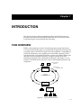
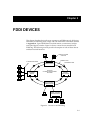
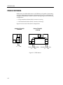
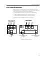
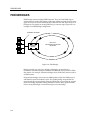
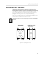
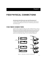
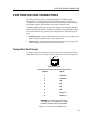
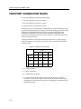
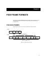


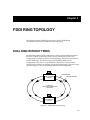
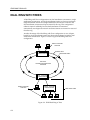
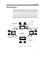
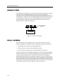
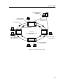
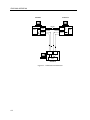
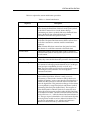

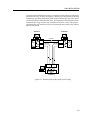
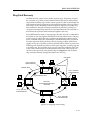
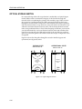
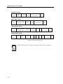
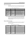
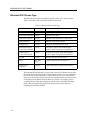
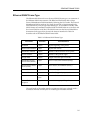
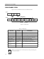
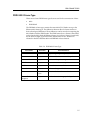
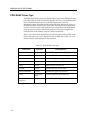
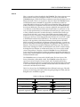
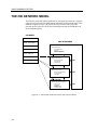
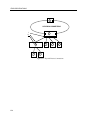


![Installation Manual [PDF 4.6 MB]](http://vs1.manualzilla.com/store/data/006008736_1-137b4e33f3bd3f098e11b56c54272240-150x150.png)