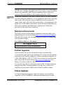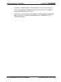
1
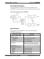
Crestron CNXBRMO
Bridging/Mono Interface
Operations Guide
This document was prepared and written by the Technical Documentation department at:
Crestron Electronics, Inc.
15 Volvo Drive
Rockleigh, NJ 07647
1-888-CRESTRON
All brand names, product names and trademarks are the property of their respective owners.
©2006 Crestron Electronics, Inc.
Crestron CNXBRMO
Bridging/Mono Interface
Contents
Bridging/Mono Interface: CNXBRMO
1
Introduction ............................................................................................................................... 1
Features and Functions ................................................................................................ 1
Applications................................................................................................................. 1
Internal Block Diagram ............................................................................................... 2
Specifications .............................................................................................................. 2
Physical Description.................................................................................................... 3
Industry Compliance ................................................................................................... 6
Setup .......................................................................................................................................... 7
Network Wiring........................................................................................................... 7
Hardware Hookup ....................................................................................................... 7
Problem Solving ...................................................................................................................... 13
Troubleshooting......................................................................................................... 13
Check Network Wiring.............................................................................................. 14
Reference Documents................................................................................................ 15
Further Inquiries ........................................................................................................ 15
Future Updates .......................................................................................................... 15
Return and Warranty Policies .................................................................................................. 17
Merchandise Returns / Repair Service ...................................................................... 17
CRESTRON Limited Warranty................................................................................. 17
Operations Guide – DOC. 8158A
Contents • i
Crestron CNXBRMO
Bridging/Mono Interface
Bridging/Mono Interface:
CNXBRMO
Introduction
Features and Functions
• Designed for use with a Crestron® CNX-PAD8A or
CNX-BIPAD8 audio distribution processor
• Facilitates bridging of a CNAMPX-16X60 or
CNAMPX-12X60 for increased power output
• Can be configured to produce a summed, mono signal with up
to four outputs (two with inverted polarity) from a single stereo
source
Applications
The CNXBRMO accepts the stereo signal from a single room output and
splits that signal into two stereo outputs, one with normal polarity and the
other with inverted polarity. These two outputs connect to the inputs of
two adjacent stereo channels on the CNAMPX amplifier. The result is
that these two channels can be used to drive a stereo pair of loudspeakers
with over 200 Watts of output power per speaker.
On either amplifier model only the first two adjacent channels and the
last two adjacent channels are bridgeable. Therefore no more than two
CNXBRMO interfaces may be used with a single CNAMPX amplifier.
The CNXBRMO can also be configured to produce a summed mono
signal.
Operations Guide – DOC. 8158A
Bridging/Mono Interface: CNXBRMO • 1
Bridging/Mono Interface
Crestron CNXBRMO
Internal Block Diagram
The following diagram represents the signal routing abilities of the
CNXBRMO. For more information refer to “Hardware Hookup” on page
7.
Internal Block Diagram of the CNXBRMO
Specifications
Specifications for the CNXBRMO are listed in the following table.
CNXBRMO Specifications
SPECIFICATION
Cresnet® power usage
Environmental
Temperature
Humidity
Enclosure
Dimensions
(including connectors)
Height
Width
Depth
Weight
2 • Bridging/Mono Interface: CNXBRMO
DETAILS
<1 Watt @ 24 Volts DC
41º to 122ºF (5º to 50ºC)
10% to 90% RH
(non-condensing)
Black metal, surface mount box
with (2) integral mounting flanges
1.26 in (3.19 cm)
5.75 in (14.61 cm)
2.54 in (6.45 cm)
0.54 lbs (0.24 kg)
Operations Guide – DOC. 8158A
Crestron CNXBRMO
Bridging/Mono Interface
Physical Description
This section provides information on the connections, controls and
indicators available on your CNXBRMO.
CNXBRMO Physical View
Operations Guide – DOC. 8158A
Bridging/Mono Interface: CNXBRMO • 3
Bridging/Mono Interface
Crestron CNXBRMO
CNXBRMO Overall Dimensions
5.75 in
(14.61 cm)
1
2
4
3
0.75 in
(1.91 cm)
2.54 in
(6.45 cm)
0.75 in
(1.91 cm)
5.25 in
(13.34 cm)
5
6
7
1.26 in
(3.19 cm)
4 • Bridging/Mono Interface: CNXBRMO
Operations Guide – DOC. 8158A
Crestron CNXBRMO
Bridging/Mono Interface
Connectors, Controls & Indicators
#
CONNECTORS,
CONTROLS &
INDICATORS
DESCRIPTION
1
OUTPUT (L & R)
2
STEREO/MONO
SWITCH
3
INVERTED OUTPUT
(L & R)
4
PWR LED
5
INPUT (L & R)
6
GROUND
7
NET1, 2
Two RCA jacks are used to
connect to a room/zone
amplifier to provide direct left
and right line-level audio.
Output impedance: 600 Ω;
Maximum output level: 2.5
Volts RMS.
Two-position toggle switch
used to select between stereo
and mono output.
Two RCA jacks are used to
connect to a room/zone
amplifier to provide inverted left
and right line-level audio.
Output impedance: 600 Ω;
Maximum output level: 2.5
Volts RMS.
Indicates 24 Volts DC power
supplied from Cresnet control
network.
Two RCA jacks are used to
connect to the CNX-PAD8A or
CNX-BIPAD8 to accept left and
right line-level audio.
Input impedance: 10 kΩ;
Maximum input level: 2.5 Volts
RMS.
(1) 6-32 screw, chassis ground
lug.
(1) 6-pin RJ-11 female;
connects to Cresnet control
network
Operations Guide – DOC. 8158A
Bridging/Mono Interface: CNXBRMO • 5
Bridging/Mono Interface
Crestron CNXBRMO
1. Crestron provides a two-foot cable assembly with the unit, part number 15717, for
network connection.
2. Use Creston’s six-conductor modular cable when connecting to the NET port.
Standard telephone cables are wired in a crisscross fashion and are not compatible
with Crestron equipment. Refer to the latest version of Network Modular Cable
Requirements (Doc. 5628), which is available from the Crestron website
(http://www.crestron.com/manuals).
Industry Compliance
As of the date of manufacture the CNXBRMO has been tested and found
to comply with specifications for CE marking and standards per EMC
and Radiocommunications Compliance Labelling.
NOTE: This device complies with part 15 of the FCC rules. Operation is
subject to the following two conditions: (1) this device may not cause
harmful interference and (2) this device must accept any interference
received, including interference that may cause undesired operation.
This equipment has been tested and found to comply with the limits for a
Class B digital device, pursuant to part 15 of the FCC Rules. These limits
are designed to provide reasonable protection against harmful
interference in a residential installation. This equipment generates, uses
and can radiate radio frequency energy and if not installed and used in
accordance with the instructions, may cause harmful interference to radio
communications. However, there is no guarantee that interference will
not occur in a particular installation. If this equipment does cause harmful
interference to radio or television reception, which can be determined by
turning the equipment off and on, the user is encouraged to try to correct
the interference by one or more of the following measures:
Reorient or relocate the receiving antenna.
Increase the separation between the equipment and receiver.
Connect the equipment into an outlet on a circuit different from
that to which the receiver is connected.
Consult the dealer or an experienced radio/TV technician for help.
6 • Bridging/Mono Interface: CNXBRMO
Operations Guide – DOC. 8158A
Crestron CNXBRMO
Bridging/Mono Interface
Setup
Network Wiring
When wiring the network, consider the following:
• Use Crestron Certified Wire.
• Use Crestron power supplies for Crestron equipment.
• Provide sufficient power to the system.
CAUTION: Insufficient power can lead to unpredictable results
or damage to the equipment. Please use the Crestron Power
Calculator to help calculate how much power is needed for the
system (http://www.crestron.com/calculators).
• To facilitate connection to a CNX-PAD8A or CNX-BIPAD8, use a
Cresnet Distribution Block (such as the C2N-HBLOCK).
For more details, refer to “Check Network Wiring” on page 14.
Hardware Hookup
Connect the
Device
Make the necessary connections as called out in the illustration that
follows this paragraph. Refer to “Network Wiring” above before
attaching the 4-position terminal block connector. Apply power after all
connections have been made.
When making connections to the CNXBRMO, consider the following:
• Use Crestron power supplies for Crestron equipment.
• The included cable cannot be extended.
The CNXBRMO serves as either a bridge for stereo/mono audio in an
audio distribution system or can provide all summed mono audio.
Stereo/Mono Bridge
In a bridged wiring configuration the CNXBRMO should only be used
with the Crestron CNAMPX-16X60 (or CNAMPX-12X60) amplifier to
provide over 200 watts of power to each speaker. Set the Stereo/Mono
switch on the CNXBRMO to create a stereo or mono bridge. Refer to the
illustrations on pages 9 & 10 for proper connections. Apply power to the
audio distribution system last.
Operations Guide – DOC. 8158A
Bridging/Mono Interface: CNXBRMO • 7
Bridging/Mono Interface
Crestron CNXBRMO
NOTE: When bridging, no more than two CNXBRMO units should be
connected to a single CNAMPX-16X60 (or CNAMPX-12X60). When
implementing a two CNXBRMO bridge, Crestron recommends
connecting one to ROOM INPUTS 1 & 2 and connecting the other to
ROOM INPUTS 7 & 8 on the CNAMPX-16X60 (or ROOM INPUTS 5
& 6 on the CNSMPX-12X60). Failure to make these connections in this
particular application may result in damage to the amplifier.
8 • Bridging/Mono Interface: CNXBRMO
Operations Guide – DOC. 8158A
Operations Guide – DOC. 8158A
CNX-PAD8A
Cresnet Distribution Block
2-Series
Control System
CNXBRMO Used as a Stereo Bridge
RIGHT
SPEAKER
SPEAKERS MUST BE CAPABLE OF
HANDLING MORE THAN 200 WATTS
LEFT
SPEAKER
NOTE:
IN A BRIDGED CONFIGURATION,
ONLY USE THE CRESTRON
CNAMPX-16X60
(OR CNAMPX-12X60)
SET TOGGLE
SWITCH TO STEREO
CNAMPX-16x60
Crestron CNXBRMO
Bridging/Mono Interface
Bridging/Mono Interface: CNXBRMO • 9
10 • Bridging/Mono Interface: CNXBRMO
CNX-PAD8A
Cresnet Distribution Block
2-Series
Control System
CNXBRMO Used as a Mono Bridge
RIGHT
SPEAKER
SPEAKERS MUST BE CAPABLE OF
HANDLING MORE THAN 200 WATTS
LEFT
SPEAKER
NOTE:
IN A BRIDGED CONFIGURATION,
ONLY USE THE CRESTRON
CNAMPX-16X60
(OR CNAMPX-12X60)
SET TOGGLE
SWITCH TO MONO
CNAMPX-16x60
Bridging/Mono Interface
Crestron CNXBRMO
Operations Guide – DOC. 8158A
Crestron CNXBRMO
Bridging/Mono Interface
All Summed Mono
To use a single CNXBRMO to provide four mono output signals (two
with normal polarity and two with inverted polarity) from a single stereo
source, simply set the Stereo/Mono switch on the CNXBRMO to Mono
and make the connections shown in the illustration on the next page.
Apply power to the audio distribution system last.
NOTE: Multiple CNXBRMO units may be used in a single “all summed
mono” system (up to four CNXBRMO units per CNAMPX-16X60 or
three CNXBRMO units per CNAMPX-12X60).
Operations Guide – DOC. 8158A
Bridging/Mono Interface: CNXBRMO • 11
12 • Bridging/Mono Interface: CNXBRMO
CNX-PAD8A
Cresnet Distribution Block
2-Series
Control System
SPEAKER
A
NOTE:
IF MORE THAN ONE SPEAKER
IS PLACED IN THE SAME ROOM,
KEEP SPEAKER A WITH D AND
B WITH C, ETC.
SET TOGGLE
SWITCH TO MONO
CNXBRMO Used to Provide All Summed Mono
SPEAKER
B
SPEAKER
C
SPEAKER
D
CNAMPX-16x60
Bridging/Mono Interface
Crestron CNXBRMO
Operations Guide – DOC. 8158A
Crestron CNXBRMO
Bridging/Mono Interface
Problem Solving
Troubleshooting
The following table provides corrective action for possible trouble
situations. If further assistance is required, please contact a Crestron
customer service representative.
CNXBRMO Troubleshooting
TROUBLE
POSSIBLE
CAUSE(S)
CORRECTIVE
ACTION
PWR LED does
not illuminate.
CNXBRMO is not
receiving power.
Hum on audio.
Grounding
problem.
Verify cable plugged
into NET port is the
correct type and that it
is secure.
Verify CNXBRMO is
grounded to
CNX-PAD8A (or
CNX-BIPAD8). If hum
persists, remove
chassis ground wire.
Operations Guide – DOC. 8158A
Bridging/Mono Interface: CNXBRMO • 13
Bridging/Mono Interface
Crestron CNXBRMO
Check Network Wiring
Use the Right
Wire
In order to ensure optimum performance over the full range of your
installation topology, Crestron Certified Wire and only Crestron Certified
Wire may be used. Failure to do so may incur additional charges if
support is required to identify performance deficiencies because of using
improper wire.
Calculate
Power
CAUTION: Use only Crestron power supplies for Crestron equipment.
Failure to do so could cause equipment damage or void the Crestron
warranty.
CAUTION: Provide sufficient power to the system. Insufficient power
can lead to unpredictable results or damage to the equipment. Please use
the Crestron Power Calculator to help calculate how much power is
needed for the system (http://www.crestron.com/calculators).
When calculating the length of wire for a particular Cresnet run, the wire
gauge and the Cresnet power usage of each network unit to be connected
must be taken into consideration. Use Crestron Certified Wire only. If
Cresnet units are to be daisy-chained on the run, the Cresnet power usage
of each network unit to be daisy-chained must be added together to
determine the Cresnet power usage of the entire chain. If the unit is
home-run from a Crestron system power supply network port, the
Cresnet power usage of that unit is the Cresnet power usage of the entire
run. The wire gauge and the Cresnet power usage of the run should be
used in the following equation to calculate the cable length value on the
equation’s left side.
Cable Length Equation
40,000
L<
RxP
Where: L = Length of run (or chain) in feet
R = 6 Ohms (Crestron Certified Wire: 18 AWG (0.75 MM 2 ))
or 1.6 Ohms (Cresnet HP: 12 AWG (4 MM 2 ))
P = Cresnet power usage of entire run (or chain)
Make sure the cable length value is less than the value calculated on the
right side of the equation. For example, a Cresnet run using 18 AWG
Crestron Certified Wire and drawing 20 watts should not have a length of
run more than 333 feet. If Cresnet HP is used for the same run, its length
could extend to 1250 feet.
14 • Bridging/Mono Interface: CNXBRMO
Operations Guide – DOC. 8158A
Crestron CNXBRMO
Bridging/Mono Interface
NOTE: Use Creston’s six-conductor modular cable when connecting to
the NET port. Standard telephone cables are wired in a crisscross fashion
and are not compatible with Crestron equipment. Refer to the latest
version of Network Modular Cable Requirements (Doc. 5628).
Strip and Tin
Wire
When daisy-chaining Cresnet units, strip the ends of the wires carefully
to avoid nicking the conductors. Twist together the ends of the wires that
share a pin on the network connector and tin the twisted connection.
Apply solder only to the ends of the twisted wires. Avoid tinning too far
up the wires or the end becomes brittle. Insert the tinned connection into
the Cresnet connector and tighten the retaining screw. Repeat the
procedure for the other three conductors.
Reference Documents
The latest version of all documents mentioned within the guide can be
obtained from the Crestron website (http://www.crestron.com/manuals).
This link will provide a list of product manuals arranged in alphabetical
order by model number.
List of Related Reference Documents
DOCUMENT TITLE
Network Modular Cable Requirements
Further Inquiries
If you cannot locate specific information or have questions after
reviewing this guide, please take advantage of Crestron's award winning
customer service team by calling the Crestron corporate headquarters at
1-888-CRESTRON [1-888-273-7876]. For assistance in your local time
zone, refer to the Crestron website (http://www.crestron.com/) for a
listing of Crestron worldwide offices.
You can also log onto the online help section of the Crestron website to
ask questions about Crestron products. First-time users will need to
establish a user account to fully benefit from all available features.
Future Updates
As Crestron improves functions, adds new features and extends the
capabilities of the CNXBRMO, additional information may be made
Operations Guide – DOC. 8158A
Bridging/Mono Interface: CNXBRMO • 15
Bridging/Mono Interface
Crestron CNXBRMO
available as manual updates. These updates are solely electronic and
serve as intermediary supplements prior to the release of a complete
technical documentation revision.
Check the Crestron website periodically for manual update availability
and its relevance. Updates are identified as an “Addendum” in the
Download column.
16 • Bridging/Mono Interface: CNXBRMO
Operations Guide – DOC. 8158A
Crestron CNXBRMO
Bridging/Mono Interface
Return and Warranty Policies
Merchandise Returns / Repair Service
1.
No merchandise may be returned for credit, exchange or service without prior authorization
from CRESTRON. To obtain warranty service for CRESTRON products, contact an
authorized CRESTRON dealer. Only authorized CRESTRON dealers may contact the factory
and request an RMA (Return Merchandise Authorization) number. Enclose a note specifying
the nature of the problem, name and phone number of contact person, RMA number and
return address.
2.
Products may be returned for credit, exchange or service with a CRESTRON Return
Merchandise Authorization (RMA) number. Authorized returns must be shipped freight
prepaid to CRESTRON, 6 Volvo Drive, Rockleigh, N.J. or its authorized subsidiaries, with
RMA number clearly marked on the outside of all cartons. Shipments arriving freight collect
or without an RMA number shall be subject to refusal. CRESTRON reserves the right in its
sole and absolute discretion to charge a 15% restocking fee plus shipping costs on any
products returned with an RMA.
3.
Return freight charges following repair of items under warranty shall be paid by CRESTRON,
shipping by standard ground carrier. In the event repairs are found to be non-warranty, return
freight costs shall be paid by the purchaser.
CRESTRON Limited Warranty
CRESTRON ELECTRONICS, Inc. warrants its products to be free from manufacturing defects in materials
and workmanship under normal use for a period of three (3) years from the date of purchase from
CRESTRON, with the following exceptions: disk drives and any other moving or rotating mechanical
parts, pan/tilt heads and power supplies are covered for a period of one (1) year; touchscreen display and
overlay components are covered for 90 days; batteries and incandescent lamps are not covered.
This warranty extends to products purchased directly from CRESTRON or an authorized CRESTRON
dealer. Purchasers should inquire of the dealer regarding the nature and extent of the dealer's warranty, if
any.
CRESTRON shall not be liable to honor the terms of this warranty if the product has been used in any
application other than that for which it was intended or if it has been subjected to misuse, accidental
damage, modification or improper installation procedures. Furthermore, this warranty does not cover any
product that has had the serial number altered, defaced or removed.
This warranty shall be the sole and exclusive remedy to the original purchaser. In no event shall
CRESTRON be liable for incidental or consequential damages of any kind (property or economic damages
inclusive) arising from the sale or use of this equipment. CRESTRON is not liable for any claim made by a
third party or made by the purchaser for a third party.
CRESTRON shall, at its option, repair or replace any product found defective, without charge for parts or
labor. Repaired or replaced equipment and parts supplied under this warranty shall be covered only by the
unexpired portion of the warranty.
Except as expressly set forth in this warranty, CRESTRON makes no other warranties, expressed or
implied, nor authorizes any other party to offer any warranty, including any implied warranties of
merchantability or fitness for a particular purpose. Any implied warranties that may be imposed by law are
limited to the terms of this limited warranty. This warranty statement supersedes all previous warranties.
Trademark Information
All brand names, product names and trademarks are the sole property of their respective owners. Windows is a registered trademark of
Microsoft Corporation. Windows95/98/Me/XP and WindowsNT/2000 are trademarks of Microsoft Corporation.
Operations Guide – DOC. 8158A
Bridging/Mono Interface: CNXBRMO • 17
Bridging/Mono Interface
Crestron CNXBRMO
This page is intentionally left blank.
18 • Bridging/Mono Interface: CNXBRMO
Operations Guide – DOC. 8158A
Crestron CNXBRMO
Bridging/Mono Interface
This page is intentionally left blank.
Operations Guide – DOC. 8158A
Bridging/Mono Interface: CNXBRMO • 19
Crestron Electronics, Inc.
15 Volvo Drive Rockleigh, NJ 07647
Tel: 888.CRESTRON
Fax: 201.767.7576
www.crestron.com
Operations Guide – DOC. 8158A
(2002179)
07.06
Specifications subject to
change without notice.