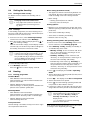
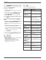
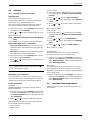
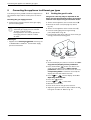
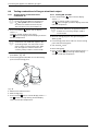
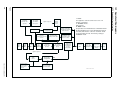
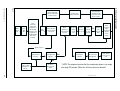
1
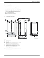
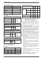
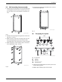
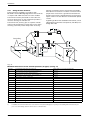
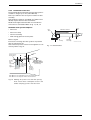
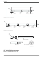
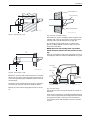
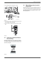
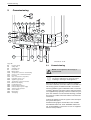
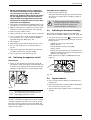
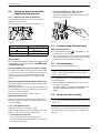
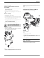
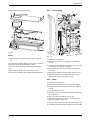
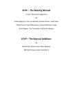
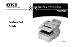
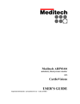
Installation
Condensate Termination and Route
External condensate pipework
The appliance has a built-in syphonic condensate trap
eliminating the need for external traps. Connect to the
22mm plastic drain pipe and extend the pipe run away
from the control panel and appliance witha constant fall
of 2.5° or 25mm in every metre. See Fig. 12
The syphonic condensate trap collects condensate into
a trap which releases it in 100 ml quantities. This helps
to prevent the discharge from freezing.
The condensate pipe can terminate into any of four
areas:
• The pipe run should take the shortest practical route.
Boiler
Boiler
Ø 22 min.
Sink
Siphon
No length
restriction
Siphon
Ø 22 min.
75 min. trap
Open end of pipe
direct into gully,
below ground but
above water level.
Use waterproof pipe work
insulation in very exposed
positions
The gradient of the discharge pipe
should be 2.5¡ (40 mm/m) minimum
Open end of pipe direct
into gully, below ground
but above water level
An internal waste system
The gradient of the discharge pipe should be
2.5¡ (40 mm/m) minimum
An external waste system
Boiler
Boiler
Internal soil
and vent stack
Ø 22 min.
Siphon
Ø 22 min.
75 min. trap
The gradient of the discharge pipe
should be 2.5¡ (40 mm/m) minimum
The rainwater system
Invert
75 min. trap
450 min.
No length
restriction
• The pipework should be insulated with weather
resistant insulation.
• The pipe should terminate as close as possible to the
ground or drain, whilst still allowing the condensate
to safely disperse. This would prevent wind blowing
up the pipe.
• The pipework should be installed with the minimum
of horizontal runs and with a downward slope of at
least 2.5 °.
3.7
No length
restriction
Sink
If there is no alternative and the condensate pipe has to
be externally run, the following should be considered:
Open end of pipe
direct into gully,
below ground but
above water level
Benchmark: For optimum performance
after installation, this boiler and its associated central heating system must be
flushed in accordance with the guidelines given in BS5793:1992 “Treatment
of water in domestic hot water central
heating systems”.
The gradient of the discharge pipe
should be 2.5¡ (40 mm/m) minimum
An external purpose made soakaway
6 720 610 596 -03.2TD
Fig. 11
Whilst all of the above methods are acceptable it is
always the best practice to terminate the condense pipe
via an internal waste system.This will eliminate the need
for any external condensate pipe runs which can be susceptible to freezing in extreme weather.
Fitting the appliance
Removing the outer case
i
The outer case is secured against unauthorised removal by a retaining bracket
(electrical safety) at the bottom left. Always secure the outer case with this
bracket again after refitting.
B Remove retaining screws (1), see Fig. 13.
B Slide the outer case upwards and forwards to
remove (2).
2
.
6 720 610 602 - 04.1O
1
6 720 610 597 -10.TD
Fig. 13
Fig. 12 Recommended route of the condensate drain
14
6 720 611 400 GB (03.11)