1
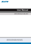
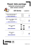
QCOLVC004-SV Interface Cable Rev. B for Sato 8400, 8450,
CL608 / CL408 / CL612 / CL412
CL608E / CL408E / CL612E / CL412E
Description and Installation Instructions
The enclosed cable, that includes an external power supply, connects a Hand Held
Products SV Series verifier to the Sato printer. A mounting stand is also required for the
SV unit. Hand Held Products offers two types of mounting stands or the application may
require a custom stand. A mounting stand is supplied separately from this kit.
Some knowledge of Hand Held Products ScanView software for SV Series setup is
highly recommended for installing and operating this system.
Note:
1. If the SATO printer has a re-winder, the re-winder will require a separate power
supply module. This power supply, SATO part #11S000120, is available through
SATO Distributors.
2. Must operate with cover open or break off the front plastic cover so laser beam is at
the tear bar. Do not break the static brush, which is located at the front plastic cover
– this will not be covered by warranty.
System Operation Overview
This interface is designed so if the verifier senses a bar code problem, the printer will
pause. In the pause condition, verifier LEDs 1 and/or 2 will be ON. To continue printing,
press and release the verifier RESET button. Note: In this system, the printer will be
operating in dispense mode. If the verifier or cable is disconnected from the
printer in this mode, the printer will not print.
Installation Procedure
1. Turn off printer power.
2. Install the SV mounting stand. (If it is a Hand Held Products “Sky Hook” it will be
mounted on the left side panel.)
3. Mount the SV unit on the stand at the approximate distance shown on the label
mounted on the side of the unit. This is preliminary for power up. Accurate
adjustment will be performed a few steps later in this procedure.
4. Connect the interface cable between the printer 14-pin I/O connector and the SV I/O
connector.
5. Connect a communication cable between the SV Comm connector and a PC running
ScanView setup software.
6. Connect the included power supply to the verifier interface cable and plug in the
power supply to turn on the SV unit.
7. The laser beam is now visible. For best results the beam must be placed in a
location where the bar codes are stable when moving through the beam.
11213033 Rev B
Page 1 of 5
8. For “picket fence” (horizontal) oriented bar codes, the recommended beam location
is on the tear bar.
9. Place a sample bar code in the center of the intended laser beam path. For best
results, this sample should match the type of bar code(s) and material that is to be
analyzed in the final application. Knowing the X dimension (narrow element width of
the bar code(s)) is required for best focus and accurate analyses. Note: SV
Calibration symbols have a 10-mil X dimension unless otherwise indicated.
10. Take a Scan Profile with ScanView.
11. Ensure the bar code(s) is in the center of the scan path.
12. Ensure the scan profile contains no distortion from light reflecting from objects in or
near the light path. Examples of a good and bad reflectance profile are shown in
Figures 1a and 1b respectively at the end of this section. One major aspect in a
good profile is the low reflectance points (the bars) in the symbol are uniform all the
way across the code. Optimum signal amplitude should be adjusted so the bar code
element reflectances are between the 90% and 10% marks shown in yellow on the
screen. Scanner angle has the most effect on the signal amplitude.
13. Continue adjusting the SV unit’s placement until a good scan profile is obtained. The
scan angle may have to be altered slightly or a light shield may have to be installed
in extreme cases to achieve a good reflectance profile. If adjustment of scan angle
does not produce the correct signal amplitude or placement, adjust scanner gain and
offset per the Adjusting Scanner Gain and Offset Section in the SV Operator’s
Guide.
14. Place ScanView in Session Mode.
15. Click on the Report an Analysis Speedbutton.
16. Ensure that X in the lower panel of the Bar Code Analysis Screen matches the X
dimension of the symbol within +/- .1 mil.
17. Adjust distance of the SV unit from the bar code until the X dimension matches the
desired value. (If X is analyzed as too large, move the scanner farther away; if X is
too small, move the scanner closer.)
18. Repeat steps 13 through 17 until no further mounting adjustments are required.
19. Remove the symbol from the laser beam path.
20. Set the verifier sync mode to edge (Command ~LX1), polarity falling edge
(Command ~LP0).
21. Set the proper SV output mode for this cable – Mode 1 is standard. Command
~LV01). See the Mode 1 description below.
22. Set the proper SV initialization (Command ~PR0210).
23. Set the verifier for the appropriate number of codes per sync interval for the
application via the ~LN Command.
24. Program the verifier’s fail parameters as desired.
25. Connect AC power cord to the printer.
26. Turn on printer power.
27. For 8400 and 8450 printers, set the printer for dispensing by pulse in Mode S and set
printer external signal to Type 1. For printer models with DIP switch settings, DIP
switch bank 3, switch 5 in the ON position provides dispensing by pulse mode. If in
doubt about setting dispensing by pulse operation, consult the printer Operator’s
Guide.
28. The verifier and printer are now ready to operate.
Figure 1a – Good Reflectance Profile
Page 2 of 5
11213033 Rev B
Example of a “good”
scan reflectance
profile:
a. Consistent
amplitude
b. Amplitude within
yellow lines.
c. Amplitude at least
6 lines high.
Figure 1b – Bad Reflectance Profile
Bar code signal
amplitude out of range:
above yellow line and
also off the graph.
Bar code low reflectance
points not in straight,
consistent values.
Mode 1 Specification
A. I/O operation
1. System will operate in Edge Sync or Envelope sync mode (~LX#)
2. Sync polarity programmable (~LP#)
3. Port 1 will go active OFF (no current) on an error condition.
4. Port 2 will go active ON (sink current) on an error condition.
5. Pushing the reset button or power re-cycle will place Ports 1 and 2 in their
inactive states and reset the # codes per sync counter.
6. Error conditions available are:
a. Partial Read (Programmable, ~LQ#, ~Lp#)
b. % decode (Programmable, ~LD##)
c. Bad Quiet Zone (~PB816xxxxxx)
d. ANSI Defects grade less than B (Programmable, ~PB806xxxxxx)
e. ANSI Decodability grade less than C (Programmable,
~PB802xxxxxx)
f. Symbol Contrast grade less than D (Programmable, ~PB804xxxxxx)
g. No Read (if sync is received)
h. Number of codes per sync programmable (~LN##)
B. LED Operation
11213033 Rev B
Page 3 of 5
1. LED1 will turn on if Outputs 1 and 2 go active due to ANSI, contrast, or quiet
zone failure
2. LED2 will turn on if Outputs 1 and 2 go active due to a partial or no read
condition
Note: Both LEDs can be on in cases where multiple bar codes are analyzed in a
sync period.
C. Calibration Procedure
Two procedures are available to calibrate the unit.
Procedure 1:
a) Remove all bar codes from the laser beam path.
b) Place the supplied calibration symbol in the laser beam in the same position
(distance and angle) as the labels to be verified will be scanned.
c) Press and hold the RESET button on the SV100 until the Calibration LED begins to
flash.
d) Release the RESET button immediately after the Calibration LED begins flashing.
e) If calibration is successful, the laser beam will go off and the Calibration LED will go
off. Remove the calibration symbol from the beam path, then Press and release
the RESET button to turn the beam on. The SV100 is now ready to operate.
f) If calibration is unsuccessful, the Calibration LED will be either on steadily or
flashing. In this case, repeat the calibration procedure.
Procedure 2:
a) Place the supplied calibration symbol in the laser beam in the same position
(distance and angle) as the labels to be verified will be scanned.
b) Send “~SC” into the SV100 serial port. This will cause the Calibration LED to flash.
c) If calibration is successful, the laser beam will go off and the Calibration LED will go
off. Remove the calibration symbol from the beam path, then Press and release
the RESET button to turn the beam on. The SV100 is now ready to operate.
d) If calibration is unsuccessful, the Calibration LED will be either on steadily or
flashing. In this case, repeat the calibration procedure.
D. SV Commands Important to this System
This system is operating in a “mode” rather than fully programmable logic. The port
activation parameters are programmable via the ~PB8 rather than ~PB1, ~PB2, etc. for
each individual port. Other commands, such as mode commands are also available. The
commands most useful for this system application are described below. Please see the
SV100 Operator’s Guide for additional command description details.
~LV01
This command sets this mode of operation.
~Lp0
This command turns off all partial decode logic at the decoder level
~Lp1
This command turns on partial decode logic at the decoder level
~LQ1
This command allows partial decodes to activate the output ports
Page 4 of 5
11213033 Rev B
~LQ0
This command disables partial decodes to activate output ports.
NOTE: In SV firmware versions x238 and lower, ~LQ commands are not
implemented and the command ~HQ1 must be used to disable partial decodes
from activating ports. In this case the standard data transmission format is
modified and ScanView will not display data characters correctly.
~LDxx
This command sets the % decode threshold for a passing condition. Partial decodes
must be enabled at the decoder level and port level for this command to be used to
activate ports.
xx = failure threshold. Example ~LD75: if 74 % or less of scans on a code were not fully
decoded, this sets a failure for this parameter.
~PB816xxx100
This command sets the minimum percent of scans on a code which calculate good quiet
zones to determine an acceptable quiet zone analysis. The field xxx is the minimum
passing threshold. Example: if xxx = 030, a minimum of 30% of all fully decoded scans
on a code must calculate a good quiet zone, or a failure condition is set for this
parameter.
~PB806xxx000
This command sets the threshold for the ANSI Defects calculation on a code to set a
failure condition. The field xxx is the passing threshold for the calculation. For example: if
xxx = 025, a Defects analysis of 26% or higher will cause a failure condition for this
parameter.
~PB802xxx100
This command sets the threshold for the ANSI Decodability calculation on a code to set
a failure condition. The field xxx is the passing threshold for the calculation. For
example: if xxx = 037, a Decodability analysis of 36% or lower will cause a failure
condition for this parameter.
~PB804xxx100
This command sets the threshold for the ANSI Symbol Contrast calculation on a code to
set a failure condition. The field xxx is the passing threshold for the calculation. For
example: if xxx = 020, a Symbol Contrast analysis of 19% or lower will cause a failure
condition for this parameter.
~LN##
This command sets the minimum number of codes to be read during a sync period. ## =
the number of codes. For example: ~LN02 causes a No Read condition to be set if less
than 2 bar codes are fully decoded during a sync interval.
~Hx
This command stores all parameters into non-volatile memory. This command should be
the last command sent after parameters are programmed via the above commands.
11213033 Rev B
Page 5 of 5