1
DOEPFER
Organ Keyboard
d3m
User's Guide
Operating and Safety Instructions
Please follow the given instructions for use of the instrument because this will guarantee
correct instrument operation. Due to the fact that these instructions touch on Product
Liability, it is absolutely imperative that they be read carefully. Any claim for defect will be
rejected if one or more of the items was observed. Disregard of the instructions can
endanger warranty.
•
•
•
•
•
•
•
•
•
•
•
•
•
•
The instrument may only be used for the purpose described in this operating manual.
Due to safety reasons, the instrument must never be used for other purposes not
described in this manual. If you are not sure about the intended purpose of the
instrument please contact an expert.
The instrument has to be shipped only in the original packaging. Any instruments shipped
to us for return, exchange, warranty repair, update or examination must be in their
original packaging! Any other deliveries will be rejected. Therefore, you should keep the
original packaging and the technical documentation.
The instrument may only be operated with the voltage written on the power input on the
rear panel. Before opening the case disconnect the power plug.
Every modification has to be carried out only at the manufacturer or an authorized
service company. Any modification not released by the manufacturer leads to the
extinction of the operation permission.
With the introduction of a third person the warranty will be lost. In case of a destroyed
warranty seal, any warranty claim will be rejected.
The instrument must never be operated outdoors but only in dry, closed rooms. Never
use the instrument in a humid or wet environment nor near inflammables.
No liquids or conducting materials must get into the instrument. If this should happen the
instrument must be disconnected from power immediately and be examined, cleaned and
eventually be repaired by a qualified person.
Never subject the instrument to temperatures above +50°C or below -10°C. Before
operation the instrument should have a temperature of at least 10°C. Do not place the
instrument into direct sun light. Do not install the instrument near heat sources.
Keep the top side of the instrument free in order to guarantee proper ventilation,
otherwise the instrument could be overheated. Never place heavy objects on the
instrument.
All cables connected with the instrument must be checked periodically. If there is any
damage the cables must be repaired or replaced by an authorized person.
Transport the instrument carefully, never let it fall or overturn. Make sure that during
transport and in use the instrument has a proper stand and does not fall, slip or turn over
because persons could be injured.
Never use the instrument in the immediate proximity of interfering electronic devices (e.g.
monitors, computers) since this could create disturbances within the instrument and
corrupt memory data.
The exchange of electronic parts (e.g. EPROMs for software update) is allowed only if
the instrument is disconnected from power supply.
When using the instrument in Germany, the appropriate VDE standards must be
followed. The following standards are of special importance: DIN VDE 0100 (Teil
300/11.85, Teil 410/11.83, Teil 481/10.87), DIN VDE 0532 (Teil 1/03.82), DIN VDE 0550
(Teil 1/12.69), DIN VDE 0551 (05.72), DIN VDE 0551e (06.75), DIN VDE 0700 (Teil
1/02.81, Teil 207/10.82), DIN VDE 0711 (Teil 500/10.89), DIN VDE 0860 (05.89), DIN
VDE 0869 (01.85). VDE papers can be obtained from the VDE-Verlag GmbH, Berlin.
d3m
Page 2
User's Guide V1.2
Servicing / Updates
There are no controls, adjustments or other elements inside the case that have to be
operated by the user.
In case of an firmware update the case has to be opened to replace the main processor by
the new version. This service has to be carried out normally by the representative or dealer
where the device has been purchased. The service is offered by the manufacturer (Doepfer,
Germany) or an authorized dealer or service company too. Please look at the web site
www.doepfer.com for a list of all authorized companies.
Any firmware update is not free of charge. The costs for material, working time and shipment
is charged to the customer.
You may even carry out firmware updates yourself at your own risk. In this case the warranty
is lost if a mistake is made during the firmware update.
Pay attention that cases that are damaged while the device has been opened/closed (e.g.
scratched surface, damaged screws) cannot be taken back and the warranty is void.
Technical data are subject to change without notice.
The topical version of this guide is available for download as pdf file on the web site
www.doepfer.com (MANUALS section).
© 2005 by
Doepfer Musikelektronik GmbH
Geigerstr. 13
82166 Graefelfing
Germany
Phone: +49 89 89809510
Fax: +49 89 89809511
www.doepfer.com
d3m
Page 3
User's Guide V1.2
Contents
Operating and Safety Instructions................................................................................2
Servicing / Updates ......................................................................................................3
Introduction ..................................................................................................................5
Connections (rear panel)..............................................................................................6
Power Supply n ......................................................................................................6
MIDI OUT o / MIDI IN p ........................................................................................6
FOOT CONTROL q ................................................................................................7
FOOT SWITCH r ...................................................................................................7
Operation .....................................................................................................................8
Play Mode .................................................................................................................9
• B4 Mode..........................................................................................................9
• EVB3 Mode...................................................................................................10
• Remote Mode ...............................................................................................10
Programming Mode ................................................................................................11
d3m
Page 4
User's Guide V1.2
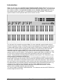
Introduction
d3m is the first part of the modular organ masterkeyboard system d3 that is intended as a
control unit for organ emulations like Native Instruments B4 or Emagic evb3. The system has
two modules available: the keyboard unit d3m and the drawbar control unit d3c. Each of
the modules can be used alone or in combination with the other modules. The maximum
system consists of two keyboards d3m and one control unit d3c.
The first part of the modular concept is d3m: a 5 octave waterfall organ keyboard with 22
buttons for program change. Following previous organ designs the buttons are organized as
10 preset bank buttons and 12 preset number buttons. Each button is equipped with a blue
LED. The 12 number buttons correspond to the different colored lowest octave that was
available in previous organs. Additionally a foot controller and a foot switch can be
connected. Both are programmable (e.g. volume for the foot controller and sustain or rotary
speaker on/off for the foot switch). The keyboard is equipped with Midi In and Midi Out. Two
(or even more) of these manuals can be daisy-chained via midi out/in as upper/lower
manual. The keyboards are distinguished by different midi channels. The connection to the
control unit d3c is established via Midi too.
Several keyboards can be mounted together. For this threads are available at the rear and
bottom side of the case. By means of corner braces the keyboard can be mounted together
in two ways: with hidden or accessible button section of the lower keyboard. These threads
are even used to mount the optional control unit d3c and other options planned for the future.
Provided that there are sufficient inquiries we think about some mechanical extensions: e.g.
a support to put a laptop on the keyboard, a music stand, additional feet for the rear
keyboard to avoid tip over and a wooden side plate for two d3m and one d3c. If these
options will be available depends upon the inquiries.
The case is made of silvergrey coated aluminium. The measures are about L87xT25xH9 cm
and the weight is about 6.5 kg.
d3m
Page 5
User's Guide V1.2
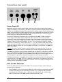
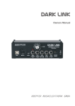
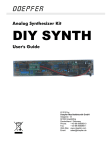
Connections (rear panel)
r
q
p
o
n
Power Supply n
d3m does not have a built-in power supply. Instead it uses a plug-in type external power
supply (AC adapter). One reason for this feature is electrical safety. Keeping danger voltages
(mains) out of the d3m increases the electrical safety. Another reason for the external power
supply is the fact that line voltages and plug types vary considerably from country to country.
Using a plug-in external supply the d3m can be used anywhere with a locally purchased
power supply, thus keeping the retail price down.
In Europe a VDE approved power supply is included with the d3m. In other countries a
power supply with suitable mains voltage and mains connector has to be purchased
separately by the user provided that the dealer resp. representative does not enclose the
power suppy. The power supply must be able to deliver 7-13 VDC unstabilized or stabilized
voltage, as well as a minimum current of 100 mA. The correct polarity of the DC voltage
connector is: outside ring = GND, inside lead = +7...13V. An external power supply of high
quality and safety should be used. If more than one d3m has to be powered by one power
supply the minimum current has to be a multiple of 100 mA (e.g. 200 mA for two d3m, 300
mA for three d3m).
Remark: The value "250mA" printed on the rear panel is no longer required. For the new
series of d3m a current of 100 mA is sufficient (but a 250 mA supply would be fine also)!
The d3m has two power supply sockets available that are internally connected. In case that
two or more d3m are operated only one power supply is required. The power supply is
connected to one of the d3m. The second d3m is connected to the second supply socket of
the first d3m via a special DC cable that is equipped with a DC plug on each side.
The d3m is switched on by plugging the AC adapter into a wall outlet and connecting it to the
appropriate jack of the d3m. There is no separate on/off switch. If the polarity of the power
supply is incorrect, the d3m will not function. However, there is no danger of damage to the
circuitry since it is protected by a diode.
MIDI OUT o / MIDI IN p
This is the Midi output resp. input of the d3m. The connection of these sockets depends
upon the type of operation:
•
Only one d3m is in use: In this case the Midi Out socket of d3m is connected to the Midi
In socket of the device to be controlled by the d3m (e.g. a computer that runs Native
Instruments' B4 or Emagic's evb3, or an organ sound generator) via a suitable Midi
cable. The Midi input of the d3m remains unconnected in this case.
d3m
Page 6
User's Guide V1.2
•
•
Two or more d3m are in use: In this case the Midi in/outputs of all d3m are daisy
chained. Midi out of the first d3m is connected to Midi in of the second, Midi out of the
second d3m is connected to Midi In of the third and so on. The Midi output of the last
d3m in the chain is connected to Midi In of the device to be controlled by the d3m (e.g. a
computer that runs Native Instruments' B4 or Emagic's evb3, or an organ sound
generator) via a suitable Midi cable. The Midi input of the first d3m remains unconnected
in this case. Each d3m requires a different Midi channel to be able to distinguish the
keyboards (see operation how to assign a Midi channel).
Two or more d3m are in use in combination with a d3c controller: The d3m and d3c are
daisy chained as described above but the d3c has to be the last link in the chain. The
Midi output of the d3c is connected to Midi In of the device to be controlled by the d3m
(e.g. a computer that runs Native Instruments' B4 or Emagic's evb3, or an organ sound
generator) via a suitable Midi cable. The Midi input of the first d3m remains unconnected.
Even in this case each d3m requires a different Midi channel to be able to distinguish the
keyboards (see operation how to assign a Midi channel).
Remark: The Midi input of d3m should be used only for connection to another d3m module.
The Midi input is not suitable for large amounts of Midi data (e.g. SysEx strings or Midi
messages coming from a computer sequencer) but only for small data rates like the
messages of another d3 module. In case of large amounts of incoming Midi messages data
loss or delay may occur.
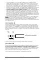
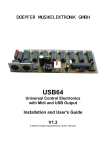
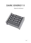
FOOT CONTROL q
This stereo jack socket can be used to connect a foot controller. Do not connect the foot
controller unless the d3m is switched off. The foot controller function is programmable (e.g.
volume, expression). For details please refer to the operation chapter. We recommend the
usage of the foot controller FP5. The foot controller is not included with the d3m and has to
be ordered separately if required. You may use even another foot controller that is connected
in this way:
high
end
low
end
Foot control connection
10-100k linear
If you do not want to use a foot controller the socket remains unconnected.
FOOT SWITCH r
This monophonic jack socket can be used to connect a (single) foot switch. Do not connect
the foot switch unless the d3m is switched off. The foot switch function is programmable
(e.g. rotary speakers, sustain). For details please refer to the operation chapter. We
recommend the usage of the foot switch VFP1. The foot switch is not included with the d3m
and has to be ordered separately if required. You may use even another foot switch that
uses a contact that is closed at rest (and opens when operated).
If you do not want to use a foot switch the socket remains unconnected.
d3m
Page 7
User's Guide V1.2
Operation
The d3m is switched on by plugging the AC adapter into a wall outlet and connecting it to the
appropriate jack of the d3m. There is no separate on/off switch.
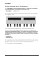
For operation d3m has 22 buttons available. Each button is equipped with a corresponding
LED (light emitting diode). The buttons are organized in two groups:
•
•
Preset Number:
Preset Bank:
12 buttons 1...12
10 buttons 1...10
The 12 number buttons correspond to the reverse colored lowest octave that was available
in some previous organs.
There are two main modes available: the play mode and the programming mode.
The play mode is the normal operation mode that is used to play on the keyboard, send
program change messages with the buttons and operate the foot controller and foot switch to
transmit the corresponding Midi messages. The play mode is called up when d3m is turned
on without operating one of the 22 buttons during power on. Corresponding to the previous
adjustments in the programming mode (see below) one of the three play modes is available
after power on:
•
•
•
B4 play mode
EVB3 play mode
Remote play mode
The programming mode is used to adjust several parameters of the d3m (e.g. Midi channel,
play mode, functions of foot controller and foot switch). The programming mode is called up
when d3m is turned on while one of the 22 buttons is held down during power on.
The different modes are now described in detail.
d3m
Page 8
User's Guide V1.2
Play Mode
To call up the normal play mode no button is allowed to be operated during power on. After
power on all LEDs turn on and go out from left to right. Now you are in the normal play mode
and are able to play on the keyboard as usual. The lowest key of the manual (C) is assigned
to Midi note number 36.
According to the adjustments in the programming mode the 22 buttons have different
functions. In the B4 mode they transmit Midi program change messages, in the EVB3 mode
both note and control change messages, in the Remote mode note messages only.
Which of the three play modes is called up after power on is adjusted in the programming
mode (refer to page 11).
•
B4 Mode
This mode is planned for the combination of d3m with the organ emulation B4 of Native
Instruments. Because of the more versatile functions – compared to the EVB3 and Remote
mode – the B4 mode can be used for other applications too, e.g. to control any Midi sound
module via the note and progam change messages that are available in B4 mode.
After power on the two LEDs Number 1 and Bank 1 light up and the Midi program change
message 0 is transmitted.
Pay attention that most manufacturers count the Midi program change numbers from
0....127 others from 1...128. In this manual we use the range 0...127 as this is more
common. If the device connected to the Midi output of d3m does not respond as
expected the different counting ranges may be the reason. In this case you simply
have to add "1" to the program change number stated in this manual. Same applies
for Midi channels too (i.e. counting from 0 to 15 resp. 1 to 16).
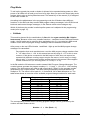
In the B4 mode the 22 buttons are used to transmit Midi Program Change Messages. The
number buttons generate the program numbers 0...11 (resp. 1...12 in the 1...128 counting
system). The bank buttons are used to add a fixed value ("offset") to the program number
generated by the number buttons. The offset value generated by the bank buttons is a
multiple of 12. The offset is 0 for bank #1, 12 for bank #2, 24 for bank #3 and so on. The
table below shows an overview of the available program change numbers for each bank:
Bank
1
2
3
4
5
6
7
8
9
10
Program number range for counting system
0 – 127
1 – 128
0 – 11
1 – 12
12 – 23
13 – 24
24 – 35
25 – 36
36 – 47
37 – 48
48 – 59
49 – 60
60 – 71
61 – 72
72 – 83
73 – 84
84 – 95
85 – 96
96 – 107
97 – 108
108 – 119
109 – 120
The corresponding formula for the resulting program change number generated by the
number and bank buttons is this:
Number – 1 + 12 x (Bank – 1)
d3m
Page 9
User's Guide V1.2
Example: Number = 5, Bank = 3
The resulting programm number is 5 – 1 + 12 x (3 –1) = 4 + 24 = 28.
The last available program change number is 119 (number #12 in bank #10). The program
change numbers 120...127 are not available. In practice the Midi program number generated
by the number and bank buttons is of minor importance as one will remind the number and
bank buttons used for a certain sound but not the program change number that is assigned
to this sound.
•
EVB3 Mode
This mode is planned for the combination of d3m with the organ emulation EVB3 of
Emagic. This software is e.g. included with Emagic's Logic.
Remark: The EVB3 has to be set to the RK mode. For details please refer to the EVB3
user's manual.
In this mode the number buttons transmit the Midi note messages 24 – 35. They correspond
to the inverse colored lowest octave of the original B3 and work like an additional lower
octave of the d3m manual. If a normal Midi sound generator is connected to the Midi output
of d3m in this mode the number buttons generate normal tones and no program change is
activated. Consequently this mode makes sense only in combination with the EVB3 as only
this software uses the Midi note numbers 24 – 35 to change the program.
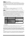
The bank buttons are used in the EVB3 mode for certain functions that cannot be stored in
the EVB3 presets. These functions are controlled "live", i.e. while playing on the keyboard.
The following table shows the function of the bank buttons in the EVB3 mode :
Bank
1
2
3
4
5
6
7
8
9
10
•
Function
Vibrato UpperManual On/Off
Vibrato LowerManual On/Off
Vibrato C1
Vibrato C2
Vibrato C3
Percussion On/Off
Percussion 2nd/3rd
Leslie Slow (Chorale)
Leslie Off (Brake)
Leslie Fast (Tremolo)
Remark
toggle function
toggle function
radio buttons
toggle function
toggle function
radio buttons
Remote Mode
This mode is planned for the combination of d3m with special software (e.g. Ableton Live). In
combination with normal Midi sound generators this mode does not make sense.
In the Remote mode the number buttons transmit the Midi note messages 0-11 and the bank
buttons the Midi note messages 14-23. In this mode the LEDs are not managed by the the
d3m but have to be controlled by the external software via incoming Midi note messages (011 for the LEDs assigned to the number buttons and 14-23 for the LEDs assigned to the the
bank buttons). All other functions (e.g. foot switch, foot controller) are the same as for the B4
mode.
Consequently this mode requires an external software that allows to assign certain functions
to the Midi note messages 0-11 and 14-23 and to control the LEDs of the d3m via Midi note
messages in a suitable way. For example Abletons's Live can be used for this purpose.
d3m
Page 10
User's Guide V1.2
Programming Mode
The programming mode is used to adjust several basic parameters of the d3m. This mode is
called up when d3m is turned on while one of the 22 buttons is held down during power on.
Even in this mode all LEDs light up after power on and go out from left to right. After that all
LEDs with exception of number 1 light up again to indicate the programming mode.
The bank buttons are used to select the parameter that has to be changed. As soon as one
of the bank buttons is operated all LEDs turn off and only the LED of the button that has
been operated lights up. After that the number buttons are used to adjust the value for the
selected parameter.
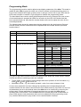
The following table shows the parameters that are assigned to the bank buttons (first and
second column) and the values that can be adjusted with the number buttons (third and
fourth column):
Bank
1
2
Parameter
Midi channel
Selected device in play mode
3
Function of the foot control
4
Function of the foot switch
5
Velocity mode
Number
1-12
1
2
3
1
2
1
2
3
4
5
6
7
8
9
10
11
1
2
3
....
11
12
Value/function of the parameters
Midi channel 1-12
B4
EVB3
Remote
Expression (Controller #11)
Volume (Controller #7)
Leslie Slow/Fast (toggle)
Leslie On/Off (toggle)
Foot control Foot control
operated
released
Leslie
Fast
Slow
Leslie
Slow
Fast
Leslie
On
Off
Leslie
Off
On
Sustain On
Off
Sustain Off
On
Vibrato On/Off (toggle)
Vibrato
On
Off
Vibrato
Off
On
dynamic (velocity activated)
fixed velocity value 20
fixed velocity value 30
...
fixed velocity value 110
fixed velocity value 127
For some of the switch functions of the foot control (Leslie Slow/Fast, Leslie On/Off, Vibrato
On/Off) two different switching modes are available:
•
•
Toggle mode: in this mode the state changes with each operation of the foot switch, e.g.
slow → fast → slow → fast and so on.
Momentary mode: e.g. foot control operated = slow, foot control released = fast
As soon as a parameter has been changed by operating the corresponding bank and
number buttons the new value is stored into the non-volatile memory of the d3m. As soon as
all parameters are set to the desired values the d3m has to be turned off by removing the
power supply. Please wait about 10 seconds and then turn on again the d3m without
operating one of the buttons. Then the d3m enters the normal play mode as described on
page 8 and uses the new parameters that have been adjusted in the programming mode.
(e.g. another Midi channel or play mode or foot controller/switch function).
.
d3m
Page 11
User's Guide V1.2
Doepfer
Musikelektronik
www.doepfer.com
© 2006 by
Doepfer Musikelektronik GmbH
Geigerstr. 13
82166 Graefelfing
Germany
Phone: +49 89 89809510
Fax: +49 89 89809511
email: [email protected]
Web Site: www.doepfer.com