1
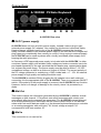
DOEPFER CV/Gate-Keyboard A-100CGK User’s Guide www.doepfer.com OPERATING AND SAFETY INSTRUCTIONS Please follow the given instructions for use of the instrument because this will guarantee correct instrument operation. Due to the fact that these instructions touch on Product Liability, it is absolutely imperative that they be read carefully. Any claim for defect will be rejected if one or more of the items was observed. Disregard of the instructions can endanger warranty. • • • • • • • • • • • • • • The instrument may only be used for the purpose described in this operating manual. Due to safety reasons, the instrument must never be used for other purposes not described in this manual. If you are not sure about the intended purpose of the instrument please contact an expert. The instrument has to be shipped only in the original packaging. Any instruments shipped to us for return, exchange, warranty repair, update or examination must be in their original packaging! Any other deliveries will be rejected. Therefore, you should keep the original packaging and the technical documentation. The instrument may only be operated with the voltage written on the power input on the rear panel. Before opening the case disconnect the power plug. Every modification has to be carried out only at the manufacturer or an authorized service company. Any modification not released by the manufacturer leads to the extinction of the operation permission. With the introduction of a third person the warranty will be lost. In case of a destroyed warranty seal, any warranty claim will be rejected. The instrument must never be operated outdoors but only in dry, closed rooms. Never use the instrument in a humid or wet environment nor near inflammables. No liquids or conducting materials must get into the instrument. If this should happen the instrument must be disconnected from power immediately and be examined, cleaned and eventually be repaired by a qualified person. Never subject the instrument to temperatures above +50°C or below -10°C. Before operation the instrument should have a temperature of at least 10°C. Do not place the instrument into direct sun light. Do not install the instrument near heat sources. Keep the top side of the instrument free in order to guarantee proper ventilation, otherwise the instrument could be overheated. Never place heavy objects on the instrument. All cables connected with the instrument must be checked periodically. If there is any damage the cables must be repaired or replaced by an authorized person. Transport the instrument carefully, never let it fall or overturn. Make sure that during transport and in use the instrument has a proper stand and does not fall, slip or turn over because persons could be injured. Never use the instrument in the immediate proximity of interfering electronic devices (e.g. monitors, computers) since this could create disturbances within the instrument and corrupt memory data. The exchange of electronic parts (e.g. EPROMs for software update) is allowed only if the instrument is disconnected from power supply. When using the instrument in Germany, the appropriate VDE standards must be followed. The following standards are of special importance: DIN VDE 0100 (Teil 300/11.85, Teil 410/11.83, Teil 481/10.87), DIN VDE 0532 (Teil 1/03.82), DIN VDE 0550 (Teil 1/12.69), DIN VDE 0551 (05.72), DIN VDE 0551e (06.75), DIN VDE 0700 (Teil 1/02.81, Teil 207/10.82), DIN VDE 0711 (Teil 500/10.89), DIN VDE 0860 (05.89), DIN VDE 0869 (01.85). VDE papers can be obtained from the VDE-Verlag GmbH, Berlin. Introduction The A-100CGK is a monophonic keyboard with CV and Gate outputs. The main application is the control of an A-100 system but even other modular systems or synthesizers can be controlled provided that they use the 1V/octave standard. In addition the A-100CGK has a Midi output. The A-100CGK is a available as a ready built device with black metal case and a four octave keyboard or as an OEM module. The OEM module contains only the electronics kit and can be combined with any Fatar keybed with 2, 3, 4 or 5 octaves (e.g. TP/6, TP/60, TP/7, TP/8S, TP/8O, TP/9). For these versions we do not offer a suitable case. Rather the case has to be built by the customer. It's also possible to install the OEM version with a suitable keybed (max. 4 octaves) into the top cover of the A-100 Monster Base. Some of the available Fatar keybeds are listed on the accessory page on our website www.doepfer.com > products > accessories. The complete overview of all keybeds can be found on the Fatar website www.fatar.com. All Fatar keybeds with up to 5 octaves can be combined with the A-100CGK OEM kit (longer keybed are not possible). These are the most important features of the A-100CGK (ready built version): slightly weighted four octaves keybed TP/9 with velocity and monophonic aftertouch • black aluminium case with white printing • available in/outputs: o CV1: controlled by the currently pressed key, 1V/octave standard, 0...+5V range (5 octaves) o CV2: controlled by the velocity, 0...+5V range o CV3: controlled by the after-touch sensor, ~ 0...+2.5V range o Gate: 0/+5V (can be changed internally to 0/+U or S-Trig, +U = voltage of the used power supply, as for this modification the case has to be openden it should be carried out by a specalized service center) o Midi In (so far not used) o Midi Out (only channel 1, with velocity, 0V CV1 corresponds to Midi note number 36) o 9V DC (for supply with an external wall outlet adapter, 7...12V are possible) o 9 pin sub-D connector with CV1, CV2, CV3, Gate, Midi Out and supply voltage (to establish a connection to the A-100 with one cable only and power the A100CGK from the A-100 frame, a suitable adapter module is in the planning stage) • • • • • • • • available menus/buttons with LEDs o Mode: selects the key for CV1 when more than one key is operated ar the same time lowest key priority highest key priority last key priority o Transpose, 2 different transpose modes can be selected in the configuration menu 0/+1 octave or 0...+12 semitones o Retrigger: this parameter controls the Gate behaviour while legato play (i.e. when a key is operated while another one is already pressed), 0 means that the Gate is not reset in this case, 1...20 defines different reset times in milliseconds. This is necessary from our experience as some ADSR generators require a longer reset time to be retriggered. For the A-100 envelope generators (e.g. A-140) setting "1" is OK, i.e. shortest reset time is sufficient. For other envelope generators the minimum reset time has to be tried out. o Hold: If this key is operated the Gate is held even if the key is released o Up/Down: buttons to increase/decrease the value of the currently selected menu. In addition the value of the selected parameter can be increased by operating the corresponding menu button again. additional basic parameters are adjusted in a special configuration mode and include parameters that are normally fixed, i.e. they are not changed during the play. The configuration mode is selected if the up or down button is held down during power on: o keybed type (2/3/4/5 octaves, necessary for transpose and offset options, has to be set to "4" for the ready built version) o transpose mode (0/+1 octave or 0...+12 semitones) o Gate polarity (useful if an inverted Gate behaviour is required, e.g. for Moog synthesizers or systems) An external power supply (7-12VDC@min. 250mA) is used. Within Europa the wall outlet power supply adapter for 230V mains voltage and European type mains plug is included with the A-100CGK. In other countries the power supply has to be purchased by the user in his country. If there is a Doepfer representative in your country (see dealer link on our website) please ask the representative if the power supply is included in your country. four 80 cm A-100 patch cables are included to connect the four outputs of the A100CGK to the A-100 system. If your system uses 1/4" jack sockets special cables (3.5 mm to 1/4" jack plug) have to be ordered separately. These cables can be found in the accessories section of the price list on our website. As soon as the A-100CGK adapter module is available the keyboard can be powered from the A-100 system. In this case no external power supply adapter is necessary. The adapter module is in the planning stage. Dimensions: ~ 790 length x 200 depth x 65 height, measures in mm (ready built version with octaves keybed and metal case) weight: ~ 4.5 kg (ready built version with octaves keybed and metal case) Connections n o p q r s t ❽ A-100CGK Rear view n 9V DC (power supply) A-100CGK does not have a built-in power supply. Instead it uses a plug-in type external power supply (AC adapter). One reason for this feature is electrical safety. Keeping danger voltages (mains) out of the A-100CGK increases the electrical safety. Another reason for the external power supply is the fact that line voltages and plug types vary considerably from country to country. Using a plug-in external supply the A-100CGK can be used anywhere with a locally purchased power supply, thus keeping the retail price down. In Germany a VDE approved power supply is included with the A-100CGK. In other countries a power supply with suitable mains voltage and mains connector has to be purchased separately by the user provided that the dealer resp. representative does not enclose the power suppy. The power supply must be able to deliver 7-12 VDC unstabilized voltage, as well as a minimum current of 250mA. The correct polarity of the DC voltage connector is: outside ring = GND, inside lead = +7...12V. An external power supply of high quality and safety should be used. The A-100CGK is switched ON by plugging the AC adapter into a wall outlet and connecting it to the appropriate jack of the A-100CGK. There is no separate ON/OFF switch. If the polarity of the power supply is incorrect, the A-100CGK will not function. However, there is no danger of damage to the circuitry since it is protected by a diode. o Midi Out This socket outputs the information generated by the A-100CGK in addition as midi messages on midi channel 1. Polyphonic note on/off messages with velocity and monophonic after-touch messages are generated. The A-100CGK was not planned as a midi keyboard but the midi output can be used to control other A-100 devices where midi note on/off data are used (e.g. the planned keyboard/sequencer controller or an analog arpeggiator with midi input). 0V control voltage at output CV1 corresponds to midi note number 36. p Midi In This connection is not used so far. q A-100 Connector This 9 pin sub-D connector can be used to establish the connection between the A100CGK and an A-100 system with one cable only by means of the planned A100CGK adapter module. The connector carries the signals Gate, CV1, CV2, CV3 and midi out. In addition the A-100CGK is powered by the power supply of the A-100 system if the adapter board is used. The power supply connector n is then no longer used. r Gate This 3,5 mm jack socket is the gate output of the A-100CGK. According to the chosen gate polarity (positive or negative) and gate voltage (+5V, power supply voltage or S-Trig) the corresponding gate signal is available at this socket. Usually this socket is connected to the gate input(s) of the envelope generator(s), e.g. ADSR's A-140, A-141 or A-143-2. If more than one envelope generator has to be triggered a multiple (A-180) or bus access module (A-185-1) can be used. For details please refer to the user manual of the corresponding module. The gate output can be used for other applications too: e.g. advance to the next step of an analog (A-155) or gate/trigger sequencer (A-160/161) or sequential switch (A151, A-152), controlling a voltage controlled switch (A-150), triggering a sampler module (A-112), resetting an LFO (A-145) and many more. In general the gate output can be used to control any gate or trigger input of an A-100 module. In addition the gate output can be processed e.g. by a slew limiter (A-170, A-171) to obtain a slowly increasing or decreasing control voltage that can be used to control other modules, e.g. the frequency of a VCLFO (A-147), or the amplification of a VCA (A-130/131/132) to obtain increasing/decreasing levels (audio or CV, e.g. LFO depth for frequency modulation). Even the usage of the gate signal as a CV input can be useful (e.g. switching between two different frequencies of a VCLFO A-147). s CV1 This 3,5 mm jack socket is the control voltage output of the A-100CGK that is controlled by the number of the key pressed on the keyboard. The voltage range is 0...+5V, the scale is 1V/octave. Inside the device there is a trimming potentiometer that can be used to re-adjust the scale if necessary. As the case has to be opened for this the procedure should be carried out by a specialized company only. Usually this socket is connected to the 1V/oct CV input(s) of the voltage controlled oscillator(s) (VCO's), e.g. A-110 or A-111-1/2. Even CV input of the sampler module A-112 can be controlled to play a recorded sample with the keyboard. If the filter used in the patch should follow the VCO frequency (called keyboard tracking) the CV1 has to be connected to the filter module too. If more than one VCO/VCF has to be controlled a multiple (A-180) can be used for signal distribution. If more than two VCO/VCFs have to be connected to the CV1 output of the A-100CGK a bus access module (A-185-1) or precision adder module (A-185-2) is recommended instead of a simple multiple to avoid signal losses that may cause scale or tuning problems. For details please refer to the user manual of the corresponding module. t CV2 This 3,5 mm jack socket is the control voltage output of the A-100CGK that is controlled by the velocity of the key pressed on the keyboard. The voltage range is 0...+5V. There are no fixed rules how to connect this socket to CV inputs of A-100 modules. For example it can be connected to the CV input of a VCA (voltage controlled amplifier, e.g. A-130, A-131, A-132-x) to control the loudness of a patch by the keyboard velocity. But it can be used also to control the frequency of a VCF (voltage controlled filter), the tempo of a VCLFO (e.g. A-147), the modulation depth of an LFO or ADSR (via an VCA), the left/right panning (A-134), or to control any other voltage controlled parameter of an A-100 module. ❽ CV3 This 3,5 mm jack socket is the control voltage output of the A-100CGK that is controlled by the after touch sensor of the keyboard. Even for this CV output there are no fixed rules how to connect it to A-100 modules. The same remarks as for CV2 are valid. The After-Touch sensor is a pressure sensor that is positioned below the keys of the keyboard. It can be used to generate an additional voltage that is controlled by the pressure applied to the currently pressed key. The sensor is not very sensitive (e.g. compared to the pressure sensor of the A-198/R2M manual). We have no influence to the sensitivity of the sensor as it is installed by the keyboard manufacturer (Fatar). You should treat it as a free add-on. Operation A-100CGK is switched on by plugging the AC adapter into a wall outlet and connecting it to the appropriate power supply socket n. There is no separate ON/OFF switch. After power on the six LEDs will light up for a short time and the display shows the software version (e.g. 100 for version 1.00). Otherwise the AC adapter used is not suitable, has the wrong polarity or does not work. Controls Display: 3 digit LED display Six buttons with corresponding LEDs: • four to select a menu (MODE, TRANSP., RETRIG., HOLD) • two as up/down buttons (UP, DOWN) A menu is activated by pressing the corresponding menu button. The active menu is indicated by an illuminated LED. The up/down buttons are used to increase/decrease the value of the currently selected parameter. In addition the value of the currently selected parameter can be increased by pressing the menu button in question again. To exit a menu another menu button has to be pressed. These menus are available: MODE This menu is used to select the assign mode, i.e. the rule which key is used to generate the control voltage CV1 if two or more keys are operated at the same time. Older monophonic synthesizers had normally one fixed assign mode. In the A100CGK one can select between these three assign modes: Display HIP Function Hight Note Polarity LOP Lowt Note Polarity LSt Last Note Polarity Explanation The highest currently pressed key is used to generate CV1. The lowest currently pressed key is used to generate CV1. The last of the currently pressed key is used to generate CV1. TRANSP. This menu is used to transpose the keyboard. According to the transpose type selected in the configuration mode (octave or semitone, see below) the transposition is made in octave or semitone intervals. The display shows the transposition in semitones: • • octave type transposition: semitone type transposition: 0 or 12 (+ one octave) 0, 1, 2, 3 to 12 (+ 1, 2, 3, …12 semitones) Remark: For the OEM versions of the A-100CGK the transposition ranges are different according to the keyboard type: • 2 octaves keyboard: 0 to 36 • 3 octaves keyboard: 0 to 24 • 4 octaves keyboard: 0 to 12 (same as described above) • 5 octaves keyboard: no transposition possible The reason for the different transpose ranges is the voltage range of CV1 (0...+5V). This corresponds to 5 octaves overall range. RETRIG. This menu is used to adjust the behaviour of the gate output in legato play (i.e. when a second key is operated while the first one is held down). The value shown in the display is the reset time of the gate output in milliseconds when another key is operated. If this parameter is set to zero no reset appears, i.e. an ADSR type envelope generator triggered by the gate signal remains in the sustain state. If the parameter is set to a value 1 … 20 the gate output is reset for a short time (the value shown in the display in milliseconds) when another key is pressed. In this case the envelope generator is triggered again. For all envelope generators of the A-100 the value 1 (i.e. 1 millisecond) is sufficient for retrigger. If other envelope generators are connected one has to find out the minimum reset time for retrigger by trial and error. HOLD When this button is operated the gate output is set to high no matter if a key is pressed or not. The hold function is displayed by the four menu LEDs. These light up whenever the hold function is active. If the hold button is operated again the hold function is cancelled. Configuration Mode: Adjustment of basic parameters Remark: If you have ordered the A-100CGK with metal case and 4 octaves keyboard, and want to use it in combination with the A-100 system it is not necessary to call up the configuration mode as the factory settings are chosen exactly for this application – unless you want to change the transpose type. Additional basic parameters are adjusted in a special configuration mode and include parameters that are normally fixed, i.e. they are not changed during the play. The configuration mode is selected if the up or down button is held down during power on. The configuration mode is indicated by CoF in the display. In addition all LEDs light up. To adjust a parameter the corresponding menu button has to be operated. Then the corresponding LED turns off while all other LEDs remain on (i.e. inverse LED display compared to the normal mode). The up/down buttons are used to increase/decrease the value of the currently selected parameter. To exit a menu another menu button has to be pressed. The four menu buttons are assigned to these basic parameters: MODE This configuration menu is used to adjust the number of octaves of the keyboard. For the standard version with metal case and 4 octaves keyboard the value has to be set to 4 (factory setting). For the OEM version the corresponding octave length has to be chosen: 2, 3, 4 or 5. This adjustment is necessary to select the correct note offset and to limit the transpose range for different keyboards. The factory setting is 4. TRANSP. This configuration menu is used to select the type of transpose: • • Oct SEM transpose in octave intervals (i.e. 12 semitones) transpose in semitone intervals The factory setting is Oct. RETRIG. This configuration menu is used to select the polarity of the gate signal: • • POS NEG positive gate polarity negative gate polarity If positive polarity is chosen the gate socket outputs a positive voltage when a key is pressed. The gate voltage turns to 0V when no key is operated. If negative polarity is selected the behaviour is the opposite, i.e. 0V when a key is operated and a positive voltage when no key is pressed. The A-100 and most of other synthesizers or systems work with positive gate polarity. Some synthesizers or systems (e.g. Moog) require a negative polarity. If the device connected to the A-100CGK works opposite (i.e. the sound disappears when a key is pressed and is triggered if a key is released) the gate polarity has to be changed. In addition the gate voltage depends upon the internal jumper setting (+5V, supply voltage or S-Trig). As the case has to be opened for this the procedure should be carried out by a specialized company only. The jumper for the gate voltage is located just behind the gate socket. It can be installed in two different positions: • • towards the 9 pin sub-D socket towards the transistor gate voltage = supply voltage (e.g. +9V) gate voltage = +5V If the jumper is removed the gate output has S-Trig or switching trigger function, i.e. the gate terminal is connected to GND (instead of a voltage output). This function have most of the Moog devices. But from our experience they work also with +5V gate voltage and inverted gate polarity so that it is not necessary to change the jumper setting (without obligation). If the device connected to the gate output uses voltage gate but does not trigger probably the level of the gate voltage is not sufficient. In this case the position of the jumper has to be changed as mentioned above and a power supply with sufficient voltage (e.g. 12V) has to be used. Typical examples are Roland synthesizers. The factory setting is positive polarity and +5V gate voltage (internal jumper). HOLD This configuration menu is not used so far. To leave the configuration mode and enter the normal operation mode the power supply has to be removed and then connected again after a few seconds without pressing one of the buttons. Then the normal operation mode is called up and the previously adjusted parameters in the configuration mode are valid (i.e. number of octaves of the keyboard, transpose type and gate polarity). Extent of delivery The A-100CGK delivery contains the following parts: 1. Ready built version with metal case and 4 octaves keyboard • • • • A-100CGK with black metal case and 4 octaves keyboard Power Supply (230V mains voltage, European type mains plug, output voltage range 7...12V, current min. 100 mA) included only for shipments within Germany, for shipments outside Germany please contact your local representative or dealer Four A-100 patch cables, length 80 cm This A-100CGK user's guide 2. OEM version • • • • A-100CGK electronic kit (two pc boards with ribbon cable to connect the boards) Power Supply (230V mains voltage, European type mains plug, output voltage range 7...12V, current min. 100 mA) included only for shipments within Germany, for shipments outside Germany please contact your local representative or dealer Four A-100 patch cables, length 80 cm This A-100CGK user's guide The keyboard, connection cable between keyboard and A-100CGK are not included with the OEM version of A-100CGK. These parts have to be ordered separately ! Please use the link accessories and spare parts of the product overview page. Prices can be found in the price list. Doepfer Musikelektronik www.doepfer.com © 2008 by Doepfer Musikelektronik GmbH Geigerstr. 13 82166 Graefelfing Germany Phone: #49 89 89809510 Fax: #49 89 89809511 Web Site: www.doepfer.de Email: [email protected]