1
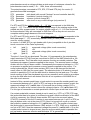
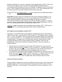
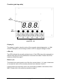
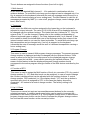
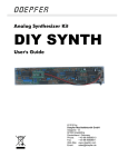
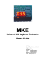
MKE
Universal Midi Keyboard Electronics
User's Guide
© 2006 by
Doepfer Musikelektronik GmbH
Geigerstr. 13
82166 Graefelfing
Germany
Phone:
#49 89 89809510
Fax:
#49 89 89809511
Web Site: www.doepfer.de
Email: [email protected]
Electrical safety / EMC compatibility
MKE is a so-called OEM product (OEM original equipment manufacturer) that cannot be
used independently but has to be combined with additional electrical or electronical
equipment to become a working device (suitable keyboard, pitch bend and modulation
wheel, rotary or fader potentiometer, power supply, case/housing). The manufacturer of MKE
does not know the final assembly of the complete device in which the MKE is used as a part
of the complete device. The final responsibility with regard to electrical safety and
electromagnetic compatibility is up to the user who is assembling the complete device.
Please pay attention to the following items:
The power supply used in combination with the MKE has to be a closed type (in Germany a
power supply with VDE approval is required). Normally an AC adapter with plastic case is
used. It is not allowed to use open power supplies with open mains voltage access (e.g.
via mains lead, pcb tracks, electronic parts).
On the MKE electronics preventing measures against electromagnetic radiation are met
(e.g. RF filters at the power supply input and the MIDI lines). But it is impossible to estimate
to what extend the components added by the user affect the EMC properties of the
complete assembly. Therefore the complete device has to be shielded against
electromagnetic radiation (incoming and outgoing). These demands are normally met by a
closed metal case that covers the complete assembly. The metal case should be connected
to GND of the MKE.
Warranty
• All connections have to be carried out in the off-state of the MKE (i.e. without power
supply)
• The MKE is an electrostatic sensitive device. Avoid any electrostatic charges !
• Do not solder directly to any of the pin headers but use female connectors to make the
connections between the MKE and your application. We offer suitable cables.
• If external momentary switches or LEDs are connected to the MKE they have to be
soldered in the off state of the MKE (i.e. without power supply)
• Applying a negative voltage or a positive voltage beyond +5V at the ADC inputs (ST3,
ST4, ST5, ST6) will destroy the circuit.
• Avoid short cuts while MKE is powered !
• Ignoring any of these items will cause warranty loss !
• Return of the MKE within the 2 weeks return time limit (valid only in Germany) is only
possible if all these items have been met. MKE that have been soldered by the customer
cannot be taken back (e.g. if external momentary switches or LEDs have been soldered to
the MKE by the user).
MKE
page 2
User's guide V2
Contents
Electrical safety / EMC compatibility ........................................................................................2
Warranty...................................................................................................................................2
Contents ...................................................................................................................................3
Introduction...............................................................................................................................4
Connections (pcb bottom side).................................................................................................6
(1) Power Supply ..................................................................................................................6
(2) Midi-Out...........................................................................................................................6
(3) Midi-In..............................................................................................................................6
(4) Keyboard connectors ......................................................................................................9
(5, 6, 7, 8) Connectors for pitch bend, modulation, volumen and sustain / after touch.........9
(9) Jumper for pull up/down resistor ST8............................................................................11
(10) sound card connector..................................................................................................11
Controls (pcb top side) ...........................................................................................................12
Display (9)...........................................................................................................................12
LEDs (10)............................................................................................................................12
Buttons (11) ........................................................................................................................12
1. Midi channel ................................................................................................................13
2. Transpose ...................................................................................................................13
3. Program Change.........................................................................................................13
4. Function of ST6...........................................................................................................13
5. Up / 6. Down ...............................................................................................................13
Parameter Storage .................................................................................................................14
Non-dynamic Operation .........................................................................................................14
Check list................................................................................................................................15
User's guide V2
page 3
MKE
Introduction
•
•
MKE is an universal Midi keyboard electronics, that can be used in
combination with these devices:
• standard keyboard (manufacturer: Fatar/Italy) with 2, 3, 4 or 5 octaves
(connected to the female headers ST1 and/or ST2)
• pitch bend wheel (special spring-loaded rotary potentiometer), connected to
the pin header ST3
• modulation wheel (special rotary potentiometer), connected to the pin header
ST4
• rotary or fader potentiometer for volume (Midi controller #7), connected to the
pin header ST4
• after touch sensor or sustain, foot switch (factory setting: sustain = Midi
controller #64), connected to the pin header ST6
• with a small circuit modification even a second rotary or fader potentiometer
can be connected to ST6 to generate any Midi controller (free adjustable Midi
control change number)
The MKE has this controls available
• 6 buttons for the functions
• Midi channel
• transpose
• program change
• function of ST6 (assignment of any Midi control change number or after
touch)
• up
• down
• 6 light emitting diodes (LEDs), assigned to the buttons
• 3 digit LED display
MKE is equipped with Midi In and Midi Out. The incoming Midi messages are
merged to the data generated by the MKE. In this way several MKE can be linked
together or combined with other OEM products (e.g. Pocket Electronics, Dial
Electronics, CTM64, MTC64) to built a user specific Midi controller. E.g. two MKE
and one CTM64 can be used to built an organ keyboard with 2 velocity sensitive
manuals (2 x MKE) and a non-dynamic bass pedal (CTM64).
MKE is available only as an assembled and tested pc board. The pc board
measures are about 68 x 85 x 45 mm. Four mounting holes with 3 mm diameter are
available for mounting the pc board to a suitable base e.g. with distance sleeves or
spacers and screws.
MKE
page 4
User's guide V2
If you order MKE in combination with one of the keyboards we have available (Fatar
TP7/2 octaves or TP/9 with 3, 4 or 5 octaves or organ keyboard TP/8O with 5
octaves) please do not forget to order the cable sets that are required to connect
MKE to the keyboard.
If MKE is ordered without keyboard please specify the length of the keyboard as
the connectors are different for 2, 3, 4 and 5 octaves.
We have suitable keyboards (2, 3, 4 or 5 octaves), keyboard connection cable sets,
pitch bend or modulation wheel kits, cable sets for ST3...6, sustain pedals and so on
available. Please look at our web price list (section spare parts resp. accessories) for
details and prices. These parts are not included with the MKE and have to be ordered
separately.
We do not offer a suitable housing as the MKE can be combined with different types
of keyboards and other OEM products (e.g. Pocket Electronics, Dial Electronics,
CTM64, MTC64) to obtain a user-specific Midi controller.
An external power supply (7-12VDC@min. 250mA) is required. It is included with
the MKE only within Germany. In other countries the external power supply has to be
ordered additionally by the local dealer if necessary.
Installation of the MKE requires some electronical knowledge (especially if wheels,
potentiometers, the after touch sensor or a sustain foot switch have to be connected
to the MKE). Please leave the installation of MKE to an expert if you are not familiar
with electronics. We take back only MKE modules in the original state, i.e. without
solder residues, without scratches and so on.
Please pay attention to the following remarks and to the warranty notes on page 2.
Ignoring these notes causes warranty loss and the right to return the goods.
User's guide V2
page 5
MKE
Connections (pcb bottom side)
Please refer to the picture on the next page.
(1) Power Supply
The MKE does not have a built-in power supply. Instead it uses a plug-in type
external power supply (AC adapter). One reason for this feature is electrical safety.
Keeping danger voltages (main) out of the MKE increases the electrical safety.
Therefore an external power supply of high quality and safety should be used. If the
keyboard is used in Germany the external power supply has to be VDE approved.
Another reason for the external power supply is the fact that line voltages and plug
types vary considerably from country to country. Using a plug-in external supply the
MKE can be used anywhere with a locally purchased power supply, thus keeping the
retail price down.
The power supply must be able to deliver 7-12 VDC unstabilized voltage, as well as a
minimum current of 250mA. The MKE is switched ON by plugging the AC adapter
into a wall outlet and connecting it to the appropriate jack on the MKE board. There is
no separate ON/OFF switch. If the polarity of the power supply is incorrect, the MKE
will not function. However, there is no danger of damage to the circuitry since it is
protected by a diode. The correct polarity is: outside ring = GND, inside lead =
+7...12V. The power supply not included with the MKE and has to be purchased
separately.
After power on the six LEDs light up for a short moment and the software version
(e.g. 1.0) is displayed.
(2) Midi-Out
Connect the Midi Out jack with Midi In of the device to be controlled by the MKE (e.g. sound
expander, computer, sequencer, synthesizer, or a second MKE or another OEM product like
Pocket Electronics, Dial Electronics, CTM64) via a suitable Midi cable.
(3) Midi-In
The MKE features a Midi input. This input may be connected to another Midi device.
The incoming Midi data are merged to the data generated by the MKE. At the first
place the Midi input is used for daisy-chaining several MKE or other OEM products
like Pocket Electronics, Dial Electronics or CTM64. The Midi input of MKE is not
suitable for large amounts of Midi (e.g. SysEx strings or Midi messages coming from
an computer sequencer). In case of large amounts of incoming Midi messages data
loss or delay may occur. If the merge feature of the MKE is not required the Midi
input is left open.
MKE
page 6
User's guide V2
(1)
power supply
7-12V/100mA
DC (BU3)
(2)
Midi Out
(BU2)
(3)
Midi In
(BU1)
(4)
keyboard connectors
ST1A/ST1B and ST2
(5,6,7,8)
connectors for
• pitch bend (ST3)
• modulation (ST4)
• volumen (ST5)
• sustain / after touch (ST6)
MKE Version 1
User's guide V2
page 7
MKE
(1)
power supply
7-12V/100mA
DC (BU3)
(2)
midi out
(BU2)
(3)
midi in
(BU1)
(10)
sound card
connector
(ST7)
(4)
keyboard connectors
ST1A/ST1B and ST2
(9)
jumper ST8
additional pullup/down resistor for
connector ST6
(Sustain/Aftertouch)
connectors for
• pitch bend (ST3)
• modulation (ST4)
• volumen (ST5)
• sustain / after touch (ST6)
MKE Version 2
MKE
page 8
User's guide V2
(4) Keyboard connectors
These two female connectors (AMP Micromatch, 16 resp. 20 pin) are used to
connect the keyboard. They are compatible to the connectors used by the keyboard
manufacturer Fatar/Italy in their 2, 3, 4 and 5 octave keyboards. To connect MKE and
the keyboard ribbon cables with 16 or 20 pins and a suitable male connector on each
end are used. The male connectors are equipped with code pins that have to fit into
the corresponding holes in the pc boards of MKE and the keyboards. If the
connectors are put on in the wrong way the MKE/keyboard combination will not work
but it is not possible to damage the electronics or the keyboard.
For the different types of keyboards these connectors are used:
keyboard type
2 octaves (25 keys)
3 octaves (37 keys)
4 octaves (49 keys)
5 octaves (61 keys)
connectors used
ST1B (one 20 pin connector)
ST1B (one 20 pin connector)
ST1A und ST2 (two 16 pin connectors)
ST1A und ST2 (two 16 pin connectors)
Offset
12
0
12
0
The offset value indicates if the contact matrix of the manufacturer (Fatar) starts with
contact number zero or if the first 12 contactes (i.e. the lowest octave) are skipped in
the contact matrix. The table shows that for the 2 and 4 octave keyboards the lowest
octave of the contact matrix is not used. This has effect only on the transposition of
the keyboard in question and causes no problems as any desired transposition can
be chosen (0, 12, 24, 36, 48 ..., see below) for the MKE. One simply selects the
desired transposition to have the keyboard in the desired Midi note range.
If a keyboard with 2 or 3 octaves is used ST2 remains unconnected. If a keyboard
with 4 or 5 octaves is used ST1A leads to the lower and ST2 to the upper half of the
keyboard.
If you have ordered the MKE without keyboard and need some information about the
type of contacts and diode matrix please look at our web site. The schematics for
keyboards with 2, 3, 4 and 5 octaves are available as pictures from the MKE
information page:
www.doepfer.com → PRODUCTS → MKE → connecting keyboards (link).
(5, 6, 7, 8) Connectors for pitch bend, modulation, volumen and sustain / after
touch
These connections are available as pin headers with three or four terminals. Version
1 of MKE is equipped with three pin headers with three pins (ST3, ST4, ST5) and
one pin header with four pins (ST6). Version 2 of MKE is equipped with four pin
headers with three pins (ST3, ST4, ST5, ST6).
The three-pin connectors (ST3, ST4, ST5, and ST6 for version 2) have these pins
available:
•
•
•
left
middle
right
(pin# 1)
(pin# 2)
(pin# 3)
GND (= potentiometer ccw terminal)
measured voltage (= potentiometer wiper terminal)
+5V (= potentiometer cw terminal)
Standard three-pin female connectors with crimped wires can be used to establish a
detachable connection (available even as spare parts from Doepfer). As the
User's guide V2
page 9
MKE
potentiometers work as voltage dividers a wide range of resistance values for the
potentiometers can be used (~ 5k ... 100k, linear recommended).
The potentiometers connected to ST3, ST4, ST4 and ST6 (only for version 2)
generate these Midi messages:
ST3
ST4
ST5
ST6
generates
generates
generates
generates
pitch bend (with a small "plateau" around controller data 64)
modulation (control change #1)
volumen (control change #7)
after touch or any control change (only version 2)
For ST3 and ST4 the voltage range ~ 0 ... 1.6 Volt corresponds to the Midi data
range 0 ... 127. The reason for this limited voltage range is the rotating angle of the
wheels we offer as spare parts. An output voltage range of ~ 0...1.6V was measured
for these wheels if they are connected to GND and +5V as they do not cover the
complete rotating angle because of the end stoppers.
For ST5 and ST6 (only version 2) the full voltage range 0 ... 5 Volt corresponds to the
Midi data range 0 ... 127 as normally standard rotary or fader potentiometers are
used for volume control.
In version 1 of MKE ST6 is a pin header with 4 pins (compatible to the 4 pin after
touch connectors of the Fatar keyboards):
•
•
•
•
left
right
(pin# 1)
(pin# 2)
(pin# 3)
(pin# 4)
measured voltage (after touch connection)
+5V
measured voltage (after touch connection)
+5V
The pins 1-3 and 2-4 are shortened. The pins 1+3 correspond to the potentiometer
wiper terminals of ST3/4/5 and are connected to GND on the MKE board with a 10k
pull down resistor. The Fatar after touch sensors function as variable resistors. The
resistance decreases if pressure applied to the sensor. The sensors forms a voltage
divider with the 10k pull down resistor. Consequently the measured voltage is ~ 0V if
no pressure is applied and increases as more pressure applied to the sensor. For
some keyboards the 10k pull down resistor (R12) has to be changed for the best
result (down to 100 Ohm for some types). The easiest solution is to solder a second
resistor in parallel to R12 until the best result is obtained by trial and error. The after
touch sensors of the Fatar keyboards are not very sensitive and it might be a problem
to dose the Midi after touch as desired. But this is not a problem of the MKE but of
the after touch sensors.
Instead of this a sustain pedal (resp. a jack socket to connect the sustain pedal) can
be connected between pin 1 and 2 of ST6: as long as the sustain contact is open the
measured voltage is 0V (→
→ Midi data = 0) because the pull down resistor R12 is
effective. As soon as the contact closes the voltage jumps to +5V (→
→ Midi data 127).
For this type of connection a sustain pedal with contact open at rest has to be used.
If a sustain pedal with contacts closed at rest is used (e.g. VFP1 or VFP2) ST6 resp.
the jack socket has to be wired in a different way and a small modification of the MKE
circuit is necessary: the 10k pull down resistor R12 has to be removed (above
ST4/ST5). Instead of this the 10 resistor is connected between pin 1 and 2 of ST6 (on
the pcb bottom side, not at the pins of ST6). Now it is turned into a pull up resistor
that pulls the measured voltage to +5V (→
→ Midi data 127). The sustain contact resp.
the jack socket is connected between GND and pin 1 of ST6. GND is e.g. available at
one pin of ST3/4/5. Now the measured voltage becomes 0V (→
→ Midi data = 0) as the
sustain pedal contact is closed at rest. As soon as the sustain pedal is operated the
pull up resistor becomes effective and Midi data 127 is generated.
MKE
page 10
User's guide V2
Another possibility is to connect a second normal potentiometer to ST6. In this case
R12 has to be removed. The ccw terminal of the additional potentiometer is
connected to GND (available at one pin of ST3/4/5), the wiper terminal is connected
to pin 1 of ST6 and the cw terminal to pin 2 of ST6 (= +5V). This potentiometer can
be used to generate any Midi controller or Midi after touch data.
Even for ST6 the full voltage range 0 ... 5 Volt corresponds to the Midi data range 0
... 127.
Important! Unused inputs of ST3/ST4/ST5 have to be jumpered to GND or +5V.
Senseless MIDI data will be sent if one of the middle pins of ST3/ST4/ST5 is left
open. For this the MKE is delivered with jumpers put on the connectors
ST3/ST4/ST5. Remove these jumpers only if the pin header in question is used to
connect a wheel, potentiometer or after touch sensor as described above. For ST6
this is not necessary because of the pull down resistor R12.
Version 2 of MKE is equipped with two additional pin headers (ST7, ST8) and the
connector ST6 is a three-pin type (please refer to the remarks above):
(9) Jumper for pull up/down resistor ST8
If a jumper is connected to this pin header the corresponding input is connected to
GND (lower position, marked with the GND symbol) or +5V (upper position, marked
with "+") via a 10k resistor. This is required if only a variable resistor or a switch has
to be connected to ST6 (i.e. not a potentiometer with three terminals that works as a
voltage divider). This applies e.g. for after-touch sensors, (foot) switches or foot
controller that have only a two-pin variable resistor available. There are two
possibilities to connect the element in question (switch or after-touch sensor or
variable resistor):
•
•
The element is connected to the pin header ST6 between the center pin and
GND. In this case a pull-up resistor to +5V is required, i.e. a jumper has to be put
on ST8 in the upper position (+). If the resistance of the element connected to
ST6 decreases even the Midi date value decreases and vice versa.
The element is connected to the pin header ST6 between the center pin and +5V.
In this case a pull-down resistor to GND is required, i.e. a jumper has to be put on
ST8 in the lower position (GND symbol). If the resistance of the element
connected to ST6 decreases the Midi date value increases and vice versa.
(10) sound card connector
This pin header is planned to connect a suitable sound card (e.g. a sound cart of the
company Dream). The four pins have these functions (from left to right): +9V, NC,
Midi Out, GND (NC = not connected). The terminal NC can be connected to +5V if
required.
User's guide V2
page 11
MKE
Controls (pcb top side)
(9)
Display
(10)
LEDs
(11)
buttons S1...S6
Display (9)
The display is used to show the value of the currently selected parameter, i.e. Midi
channel, transpose, control change number of ST6 or program change number.
LEDs (10)
The LEDs indicate the currently selected menu. If the LEDs have to be arranged in a
different way they can be de-soldered an connected via cables. Please refer to the
warranty remarks on page 5.
Buttons (11)
The buttons are used to select one of the four menus (button 1...4) resp. to decrease
or increase the value of the currently selected menu (buttons 5 and 6).
If other buttons are used they have to be connected in parallel to the buttons of the
MKE. Please refer to the warranty remarks on page 5.
MKE
page 12
User's guide V2
The six buttons are assigned to these functions (from left to right):
1. Midi channel
In this menu the desired Midi channel 1...16 is selected in combination with the
up/down buttons. To avoid Midi note hang ups the channel can be changed only if no
key is pressed on the keyboard (otherwise the note off message would be sent on a
different Midi channel causing a never ending tone). The Midi channel is valid for all
messages generated by MKE (i.e. note on/off, program change, control change, pitch
bend, after touch).
2. Transpose
In this menu the Midi note number assigned to the lowest key on the keyboard is
adjusted in octave intervals. The value (0,12,24,36,48 and 60) is displayed and can
be changed with the up/down buttons. The lowest note key is always a "C". Only the
octave of the "C" can be changed. Please refer to the remarks corresponding to
different keyboard types on page 9 . For Fatar keyboards with 2 or 4 octaves 12 has
to be added to obtain the lowest Midi note of the keyboard as the first octave of the
internal contact matrix is not used for these keyboards. To avoid Midi note hang ups
the transposition can be changed only if no key is pressed on the keyboard
(otherwise the note off message would be sent in a different transposition causing a
never ending tone).
3. Program Change
This menu is used to transmit Midi program change messages. The present program
change number is displayed and can be changed with the up/down buttons. If this
menu is called up for the first time after power on the displayed program change
number is sent out via Midi – even without operating the up/down buttons. The
reason for this feature is that the displayed program change number should
correspond to the active program change number of the Midi device controlled by the
MKE.
4. Function of ST6
This menu is used to assign the Midi function of the 4 pin connector ST6. Any control
change number (0...127) and after touch can be assigned. In case of control change
the number is displayed and can be adjusted with the up/down buttons. If control
change number 128 is selected (i.e. if the display shows "127" and the up button is
operated) after touch is assigned to ST6. In this case the display shows the
characters " At" instead of a control change number. The factory setting is 64
(sustain).
5. Up / 6. Down
These are no menus but work as increment/decrement buttons for the currently
selected parameter. In addition each menu button can be used to increment the
parameter of the menu in question. E.g. if the program change menu is selected the
program change menu button can be used to increase the program change number
too and has the same function as the normal up button.
User's guide V2
page 13
MKE
Parameter Storage
Whenever one changes from one menu to another the parameter of the preceeding
menu is stored non-volatile in the MKE memory. After the next power on these values
are chosen. These values are stored: Midi channel, transpose, program change
number, function of ST6, dynamic/non-dynamic operation.
Non-dynamic Operation
MKE was developed to be combined with velocity-sensitive keyboards manufactured
by Fatar. For certain applications (e.g. organ keyboards, bass pedals) it might be
desirable to turn off the Midi velocity and replace the variable velocity value in the
note on message by a fixed value.
To select the non-dynamic mode one has to operate one of the control buttons during
power on. Then the display shows "CoF" (abbreviation of "configuration") instead of
the software version number and the 6 LEDs work inverted, i.e. all LEDs light up
except the LED of the currently selected menu. The most left button (Midi channel
menu in normal operation) is used to adjust the fixed velocity value in the range
1...127 in combination with the up/down buttons. If this parameter is set to 0 (zero)
the dynamic mode is active again. The remaining 3 menu buttons have no function. If
the desired velocity value is adjusted the MKE is turned off. After about 5-10 seconds
it is powered again without operating one of the buttons. Now the normal operation
mode is called up (the display shows the software version) with the new velocity
value adjusted in the configuration mode.
MKE
page 14
User's guide V2
Check list
In case that your MKE does not work at the first go please check the following points:
• Is the power supply working correctly ? After power on the display has to show
the software version (e.g. "1.10") and all LEDs have to be off ! Otherwise the AC
adapter used is not suitable, has the wrong polarity or does not work. The correct
polarity is: outside ring = GND, inside lead = +7...12V.
• Are the Midi connections between MKE and the other Midi devices installed
correctly ? Midi Out of the MKE has to be connected to Midi In of the device
controlled by MKE. Especially when computers are used Midi In and Out are very
often mixed up by the user.
• Please use only cables that are suitable for Midi.
• If all that is correct but playing on the keyboard seems not to generate Midi note
messages check if the keyboard is connected in the right way as described on
page 9 and if the Midi channel of the MKE corresponds to the Midi channel of the
receiver.
• If you use another keyboard than the Fatar types (e.g. if you have built your own
keyboard or contact matrix) double check if your contact matrix and the connectors
is identically to the Fatar keyboards. The schematics for the Fatar keyboards with
2, 3, 4 and 5 octaves are available as pictures from the MKE information page:
www.doepfer.com → PRODUCTS → MKE → connecting keyboards (link)
• If wheels, potentiometer, sustain pedal or after touch sensor are used check if they
are connected in the right way to the MKE. Unused inputs (ST3/ST4/ST5) have to
be terminated with jumpers if not in use as described in the manual.
• If one of the wheels or the potentiometer work inverted it is connected in the wrong
way (GND and +5V mixed up).
• If the MKE generates no velocity check if a fixed velocity value has been set.
User's guide V2
page 15
MKE
MKE
page 16
User's guide V2
Appendix: Connecting the After Touch of Fatar keyboards:
MKE
ST8
Jumper
ST6
NC
(GND)
+5V
after touch connector
of the Fatar keyboard
The value of the pull-down resistor R12 (10k) can be reduced to obtain a different behaviour
of the after touch sensor.
Doepfer
Musikelektronik
www.doepfer.com
User's guide V2
page 17
MKE