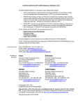
1
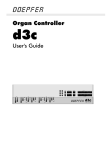
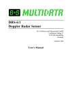
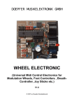
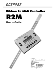
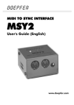
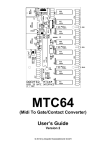
DOEPFER
Midi Bass Pedal Electronic Kit
MBP25
User's Guide
© 2008 by
Doepfer Musikelektronik GmbH
Geigerstr. 13
82166 Graefelfing
Deutschland / Germany
Phone:
+ 49 89 89809510
Fax:
+ 49 89 89809511
Web Site: www.doepfer.com
Email:
[email protected]
Electrical safety / EMC compatibility
MBP25 is a so-called OEM product (OEM original equipment manufacturer) that
cannot be used independently but has to be combined with additional electrical or
electronical equipment to become a working device (suitable keyboard, pitch bend
and modulation wheel, rotary or fader potentiometer, power supply, case/housing).
The manufacturer of MBP25 does not know the final assembly of the complete
device in which the MBP25 is used as a part of the complete device. The final
responsibility with regard to electrical safety and electromagnetic compatibility is
up to the user who is assembling the complete device.
Please pay attention to the following items:
The power supply used in combination with the MBP25 has to be a closed type (in
Germany a power supply with VDE approval is required). Normally an AC adapter
with plastic case is used. It is not allowed to use open power supplies with open
mains voltage access (e.g. via mains lead, pcb tracks, electronic parts).
On the MBP25 electronics preventing measures against electromagnetic
radiation are met (e.g. RF filters at the power supply input and the MIDI lines). But it
is impossible to estimate to what extend the components added by the user affect
the EMC properties of the complete assembly. Therefore the complete device has
to be shielded against electromagnetic radiation (incoming and outgoing). These
demands are normally met by a closed metal case that covers the complete
assembly. The metal case should be connected to GND of the MBP25.
Warranty
• All connections have to be carried out in the off-state of the MBP25 (i.e. without
power supply)
• The MBP25 electronics is an electrostatic sensitive device. Avoid any electrostatic
charges !
• Do not solder directly to any of the pin headers but use connectors to make the
connections between the MBP25 and your application.
• Applying a negative voltage or a positive voltage beyond +5V at any of the inputs
will destroy the circuit.
• Avoid short cuts while MBP25 is powered (e.g. caused by metallic or conducting
supports) !
• Ignoring any of these items will cause warranty loss !
• Return of the MBP25 within the 2 weeks return time limit (valid only in Germany)
is only possible if all these items have been met. MBP25 that have been soldered
or modified by the customer cannot be taken back.
Electronic basic knowledge is required to install the MBP25 electronic kit. If
you are not sure whether your knowledge is sufficient please consult an expert.
We cannot take back modules that became defective because of wrong
installation or wrong connection of the controls or voltages. We also cannot
take back modules or cables which have been soldered by the user.
MBP25
Page 2
User's Guide
Table of contents
Electrical safety / EMC compatibility ........................................................................................2
Warranty...................................................................................................................................2
Table of contents......................................................................................................................3
Introduction...............................................................................................................................4
Connections .............................................................................................................................6
(1) Power Supply ..................................................................................................................6
(2) Midi Out ...........................................................................................................................6
(3) Midi In..............................................................................................................................6
(4) Bass Pedal Connectors...................................................................................................8
(5) Connector for Volume Control.........................................................................................8
Controls .................................................................................................................................10
1. Midi Channel ...............................................................................................................10
2. Transpose ...................................................................................................................11
3. Program Change 1......................................................................................................11
4. Mode ...........................................................................................................................11
Parameter Storage .................................................................................................................12
Configuration Mode ................................................................................................................12
Check list................................................................................................................................12
Shortening the second bass pedal .........................................................................................13
Schematics PD/3....................................................................................................................16
User's Guide
page 3
MBP25
Introduction
MBP25 is an electronic kit that has been developed for midi bass pedal applications.
Unfortunately our supplier (Fatar) does not offer bass pedals with 25 or more keys
but only versions with 13 or 17 keys. As many customers have been asking for a
basspedal with 25 keys we decided to develop an electronic kit that can be used to
connect two bass pedals with 13 keys each (Fatar PD/3) to obtain a 25 key bass
pedal in a very economic way. Of course MBP25 can be used also in combination
with one PD/3 only. The picture below shows one possibility how two PD/3 pedals
can be combined to a 25 key pedal and built into a black varnished wooden case (the
electronics is not to be seen).
The construction is made of two 13 keys pedals PD/3 and the MBP25 electronic kit.
One of the two pedals has to be shortended by one key as one of the "C" keys is
redundant. Fortunately the PD/3 pedals use a plastic frame and can be shortened
with passable effort. In this user's manual the shortening and wiring of the two bass
pedals is described later. A bit mechanical skills and suitable tools are required
(soldering iron, saw, screwdriver). Both pedals can be mounted on a common base
plate and covered by a suitable case (e.g. made of varnished wood - as shown
above) can be added. The base plate and the case are not included and have to be
added by the customer. We do not offer these parts.
The MBP25 electronic kit is already prepared to connect a third pedal so that even
bass pedals with up to 36 keys are possible (in this case the upper "C" of two pedals
has to be removed). For this version a special cable has to be used that leads to the
second and third pedal.
In addition a rotary or slider potentiometer can be connected to transmit midi volume
data (midi control change #7).
MBP25 is available only as an assembled and tested pc board. The pc board
measures are about 82 mm (length) x 73 (width) x 25 mm (height). Four mounting
holes with 3 mm diameter are available for mounting the pc board to a suitable base
or front panel e.g. with distance sleeves or spacers and screws.
Remark: All basspedals manufactured by Fatar that include velocity are equipped
with solid steel frames and cannot be shortened in such an easy way. In addition the
connectors of PD/3 and PD/2A are not compatible.
MBP25
Page 4
User's Guide
These are the most important features of the MBP25:
•
•
•
•
•
•
•
•
•
•
•
•
•
•
•
•
three versions available:
• elektronic kit only
• elektronic kit with one 13-key bass pedal and connection cable
• elektronic kit with two 13-key bass pedals and connection cables
6 black rectangle momentary buttons (about 12 x 22 mm) with integrated LEDs to
adjust the parameters (e.g. Midi channel, transpose, mode), measures of the
complete button area about 76 x 22 mm
3-digit LED display (about 19 x 38 mm) for parameter display
two connectors for basspedals (compatible to Fatar PD/3)
fully polyphonic midi out
midi channel 1...16
transposition in six octave intervals (lowest key = midi note number 0, 12, 24, 36,
48, 60)
Midi In, Midi Out (connected via 30 cm long cables to enable the mounting of the
sockets at the desired position)
The data appearing at the Midi in are merged to the data generated by the
MBP25. Consequently the MBP25 can be connected to a Midi keyboard to add
the basspedal data to the keyboard data.
power supply socket on board, in addition a 2-pin connector is available to
connect another power supply socket near the Midi sockets
a 3-pin connector is available to connect a rotary or fader potentiometer that
transmits Midi volume, even a foot controller (e.g. FP5) can be connected.
Operating modes:
• Note mode: this is the usual play mode. The bass pedal keys are used to
transmit Midi note on/off message on the desired Midi channel and
transposition. The velocity value is fixed and can be set by the user.
• Program change mode 1: in this mode the up/down buttons are used to
transmit midi program change messages while the keys of the bass pedal can
be used to play in the usual way
• Program change mode 2: in this mode the bass pedal keys are used to
transmit Midi program change messages, the first 10 keys ("C" to "A")
correspond to the numbers 0 to 9 like a pocket calculator, the selected number
is shown in the display. The "Bb" key has delete function (i.e. set to zero) and
the "B" key transmits the currently displayed program change number (enter
function). In this mode the bass pedal keys cannot be used to play (i.e. they do
not transmit note messages)
• Realtime mode: in this mode the keys "C", "D" and "E" are used to transmit the
midi messages start, continue and stop, the other keys have normal function
(i.e. they transmit midi note messages).
An external power supply (7-12VDC@min. 250mA) is used. Within Europe the
wall outlet power supply adapter for 230V mains voltage and European type
mains plug is included with the MBP25. In other countries the power supply has to
be purchased by the user in his country. If there is a Doepfer representative or
dealer in your country please ask the representative or dealer if the power supply
is included in your country.
Dimensions of the pc board: about 82 mm (length) x 73 (width) x 25 mm (height)
Dimension of one bass pedal: about 530 mm (length) x 380 mm (depth) x 95 mm
(height)
Dimension of two bass pedals: about 980 mm (length) x 380 mm (depth) x 95 mm
(height)
User's Guide
page 5
MBP25
Connections
Please refer to the picture on the next page.
(1) Power Supply
The MBP25 does not have a built-in power supply. Instead it uses a plug-in type
external power supply (AC adapter). One reason for this feature is electrical safety.
Keeping danger voltages (main) out of the MBP25 increases the electrical safety.
Therefore an external power supply of high quality and safety should be used. If the
device is used in Germany the external power supply has to be VDE approved.
Another reason for the external power supply is the fact that line voltages and plug
types vary considerably from country to country. Using a plug-in external supply the
MBP25 can be used anywhere with a locally purchased power supply, thus keeping
the retail price down.
The power supply must be able to deliver 7-12 V stabilized or unstabilized DC
voltage, as well as a minimum current of 250mA. The MBP25 is switched ON by
plugging the AC adapter into a wall outlet and connecting it to the appropriate jack on
the MBP25 board. There is no separate ON/OFF switch. If the polarity of the power
supply is incorrect, the MBP25 will not function. However, there is no danger of
damage to the circuitry since it is protected by a diode. The correct polarity is: outside
ring = GND, inside lead = +7...12V. The power supply not included with the MBP25
and has to be purchased separately.
After power on the six LEDs light up for a short moment and the software version
(e.g. 100 for version 1.00) is displayed. After a while the operating mode is displayed
(note or program change or real time, see below mode).
(2) Midi Out
Connect the midi out jack with midi In of the device to be controlled by the MBP25
(e.g. sound expander, computer, sequencer, synthesizer) via a suitable midi cable.
(3) Midi In
The MBP25 features a midi input. This input may be connected to another midi
device. The incoming midi data are merged to the data generated by the MBP25. At
the first place the midi input is used for the combination of the MBP25 with a midi
keyboard (e.g. MKE, CTM64 or another midi keyboard). The midi input of MBP25 is
not suitable for large amounts of Midi (e.g. SysEx strings or Midi messages coming
from an computer sequencer). In case of large amounts of incoming Midi messages
data loss or delay may occur. But for midi keyboards the data rate of the MBP25 midi
input is sufficient. If the merge feature of the MBP25 is not required the Midi input is
left open.
MBP25
Page 6
User's Guide
feedback terminal for
optional third pedal
(MK4)
(4)
bass pedal connectors
ST1 (lower)
and ST2 (upper)
(5)
connector for
volume control
(ST3)
(2)
midi out
(BU1)
(3)
midi in
(BU2)
alternative
alternative
connector for midi connector for midi
out socket
in socket
(JP4)
(JP3)
(1)
power supply
7-12V/100mA
DC (BU3)
alternative
connector for
power supply
(JP2)
trimming potentiometer for
voltage range adjustment
of the volume control
connected to ST3
User's Guide
page 7
MBP25
(4) Bass Pedal Connectors
These female connectors are used to connect the bass pedal(s). The connectors are
compatible to the connectors of the Fatar PD/3 bass pedals and the same type of
connectors are used (AMP micromatch 16 pins). To connect MBP25 with the bass
pedal(s) 16 pin ribbon cables with a 16 pin male connector on each end is used. The
connectors are equipped with code pins that have to fit into the corresponding hole
on the MBP25 and PD/3 pc boards. Otherwise the pin may break off. Please check
the correct polarity of the code pin before you put up the connector. If the connector
is put up in the wrong way the bass pedal will not work but there is no risk to damage
the electronics.
If only one PD/3 bass pedal is used it is connected to ST1/LOWER.
If two PD/3 bass pedals are used the lower is connected to ST1/LOWER and the
upper to ST2/UPPER.
If the pc board is mounted to a front panel the ribbon cable connected to ST2/UPPER
has to be bended by 90 degrees to lead the cable lateral from the display.
It is possible to connect even a third bass pedal to the MBP25 electronics. In this
case a special ribbon cable with three male connectors has to be used that leads
from ST2/UPPER to two bass pedals. In addition the feedback line of the third pedal
has to be wired manually to the solder pin labelled JP1/MK4. If you want to connect a
third pedal please contact us concerning this special cable and wiring as we do not
offer a package with 3 pedals (use the email address [email protected]).
If you want to use the MBP25 not in combination with the Fatar bass pedal PD/3 but
with another bass pedal (or even single contacts or switches) the contacts have to be
wired as a diode matrix. You find the corresponding schematics at the end of this
manual.
(5) Connector for Volume Control
Remark: In the following the terms GND (= abbreviation of ground) and 0V (zero
volts) are used synonymous.
The pin header ST3 with three pins is used to connect the volume control. The pins
of the connector have these functions:
Position
Function
To be connected to ...
end terminal #1 of the potentiometer
(the terminal that corresponds to Midi data 0)
left
GND
center
measuring input (control
voltage)
center terminal of the potentiometer
right
+5V
end terminal #2 of the potentiometer
(the terminal that corresponds to Midi data 127)
The wires leading to the potentiometer can be soldered directly to the pins of ST3.
But it's also possible to use a prepared standard 3-pin female connector with cable.
As the potentiometer is used as a voltage divider between GND and +5V the
resistance value of the potentiometer is not crucial. Any value between about 5k and
500k (linear) will work.
MBP25
Page 8
User's Guide
The potentiometer connected to ST3 generates midi volume data (control change
#7). If no potentiometer is connected to ST3 the center pin has to be connected to
+5V. For this ST3 is equipped with a jumper in the factory. An open center pin of ST3
will cause the transmission of random midi volume data !
By means of a trimming potentiometer the maximal voltage value for the
potentiometer connected to ST3 can be adjusted in a range of about +3.5V...+5V.
This value corresponds to midi data 127. This feature is useful if a potentiometer is
used which does not cover the whole rotating angle. This applies e.g. for some foot
controllers (e.g. Fatar FP5). In this case not the full midi data range 0...127 would be
covered without this feature.
The factory setting is +5V. In this case the trimming potentiometer is adjusted fully
clockwise. If a potentiometer is connected to ST3 that covers the full rotating angle
this setting remains unchanged. A normal rotating potentiometer with knob or a
slider/fader potentiometer meets these requirements.
If a potentiometer is connected to ST3 that does not cover the full rotating angle (e.g.
the foot controller FP5) the trimming potentiometer has to be adjusted. This is the
adjustment procedure:
•
•
turn the potentiometer connected to ST3 to it's maximum position
turn the trimming potentiometer beginning with the fully clockwise position until
the max. midi data (127) is transmitted. If the midi volume data cannot be
measured the adjustment can be done by ear too: turn the trimming potentiometer
until the max. loudness is reached.
If the trimming potentiometer is adjusted too far the volume function will no longer
work. Only about 30% of the adjustment angle (beginning from fully clockwise) are
allowed. The trimming potentiometer is connected to GND and +5V and the
adjustable voltage range has to be +3.5 ... +5V. Values less than 3.5V are not
allowed as the reference voltage of the ADC used (analog-to-digital converter) has to
be in the range +3.5 ... +5V. Otherwise the ADC will not work correctly.
User's Guide
page 9
MBP25
Controls
The three-digit display is used to show the value of the currently selected parameter,
i.e. midi channel, transpose, program change number or mode. The LEDs indicate
the currently selected menu.
The four left buttons are used to select one of the four menus. The two right buttons
are used to decrease or increase the value of the currently selected parameter. In
addition each menu button can be used to increment the parameter of the menu in
question. E.g. if the program change menu is selected the program change menu
button can be used to increase the program change number too and has the same
function as the UP button.
The four left buttons are assigned to these menus or functions (from left to right):
1. Midi Channel
In this menu the desired midi channel 1...16 is selected in combination with the
up/down buttons. To avoid midi note hang ups the channel can be changed only if no
key is pressed on the pedal. Otherwise the note off message would be sent on a
different midi channel causing a never ending tone. The midi channel is valid for all
messages generated by MBP25 (i.e. note on/off, program change, volume).
MBP25
Page 10
User's Guide
2. Transpose
In this menu the midi note number assigned to the lowest key on the lower pedal is
adjusted in octave intervals. The value (0,12,24,36,48 and 60) is displayed and can
be changed with the up/down buttons. The lowest note key is always a "C". Only the
octave of the "C" can be changed. To avoid midi note hang ups the transpose can be
changed only if no key is pressed on the pedal. Otherwise the note off message
would be sent on a different note number causing a never ending tone.
3. Program Change 1
This menu is used to transmit midi program change messages. The present program
change number is displayed and can be changed with the up/down buttons. If this
menu is called up the displayed program change number is sent out via midi – even
without operating the up/down buttons. The reason for this feature is that the
displayed program change number should correspond to the active program change
number of the midi device controlled by the MBP25 (e.g. after power on).
In Program Change mode 1 one can play in the normal way with the keys of the bass
pedal, i.e. they transmit midi note on/off data.
4. Mode
This menu is used to select one of the three basic modes of the MBP25:
•
•
•
Note mode
Program Change mode 2
Real Time mode
The Note mode is the usual play mode. When this mode is selected the display
shows "not" and the bass pedal keys are used to transmit Midi note on/off messages.
The Midi channel selected in menue 1 and transposition selected in menu 2 are used
for the note messages. The velocity value is fixed but can be set by the user in a
special configuration mode (see below) .
In the Program Change mode 2 the bass pedal keys are used to transmit midi
program change messages. When this mode is selected the display shows "Prg" and
the first ten keys of the bass pedal ("C" to "A") correspond to the numbers 0 to 9 like
a pocket calculator. The currently selected number is shown in the display. The "Bb"
key has delete function (i.e. it sets the value to zero) and the "B" key transmits the
currently displayed program change number (enter function). In this program change
mode 2 the bass pedal keys cannot be used to play, i.e. they do not transmit note
messages. They are only used to generate program change messages.
In the Real time mode three of the bass pedal keys are used to transmit midi real
time program change messages. When this mode is selected the display shows "rtI"
and the keys "C", "D" and "E" are used to transmit the midi messages start, continue
and stop. All other keys have normal function (i.e. they transmit midi note messages).
User's Guide
page 11
MBP25
Parameter Storage
Whenever one changes from one menu to another the parameter of the preceeding
menu is stored non-volatile in the MBP25 memory. After the next power on these
values are chosen. These values are stored: midi channel, transpose, program
change number and mode.
Configuration Mode
In this special mode all parameters can be adjusted that have basic functions and are
normally adjusted once only. So far only the velocity value for the note messages
transmitted by the MBP25 can be adjusted in this mode.
To select the configuration mode one has to operate one of the menu buttons during
power on. Then the display shows "CoF" (abbreviation of "configuration") instead of
the software version number and the 6 LEDs work inverted, i.e. all LEDs light up
except the LED of the currently selected menu.
The most left button (midi channel menu in normal operation) is used to adjust the
fixed velocity value in the range 1...127 in combination with the up/down buttons. The
remaining 3 menu buttons have no function.
When the desired velocity value is set the MBP25 has to be turned off. After about 10
seconds it has to be powered again without operating one of the buttons. Now the
normal operation mode is called up (the display shows the software version and then
the mode).
Check list
In case that your MBP25 does not work at the first go please check the following
points:
• Is the power supply working correctly ? After power on the LEDs has to light up
for a short time, the display has to show the software version (e.g. "100") and then
to show the mode ("not", "Prg" or "rtI"). Otherwise the AC adapter used is not
suitable, has the wrong polarity or does not work. The correct polarity is: outside
ring = GND, inside lead = +7...12V.
• Are the midi connections between MBP25 and the other midi devices installed
correctly ? Midi out of the MBP25 has to be connected to midi in of the device
controlled by MBP25. Especially when computers are used midi in and out are
very often mixed up by the user.
• Please use only cables that are suitable for Midi.
• If all that is correct but playing on the bass pedal seems not to generate midi
messages check if the pedal(s) are connected in the right way and if the midi
channel of the MBP25 corresponds to the midi channel of the receiver.
• If you use another bass pedal than the Fatar PD/3 (e.g. if you have built your own
bass pedal or switch matrix) double check if your matrix and the connectors is
identically to the Fatar keyboards.
• If a potentiometer is used check if it is connected in the right way to the MBP25.
An unused input (ST3) has to be terminated with a jumper !
• If the potentiometer works inverted it is connected in the wrong way (GND and +5V
mixed up).
• Check also if a sufficient fixed velocity value has been set (e.g. you will hear
nothing with velocity 1 or 2).
MBP25
Page 12
User's Guide
Shortening the second bass pedal
If a 25 keys bass pedal has to be made by the combination of two 13 keys pedals one of the
two pedals has to be shortended as one of the "C" keys is redundant. Fortunately the PD/3
pedals use a plastic frame and can be shortened with passable effort. From our experience
it's easier to remove the upper key of the lower pedal though it would be possible too to
remove the lower key of the upper pedal. In the following the shortening procedure is
described.
Mark a cutting line with a
distance of about 32-34 mm
from the pcb edge to the
bottom of the pcb.
Cut off the pcb at his line with a
suitable saw.
Pay attention not to damage
the red 16 pin connector on the
other side of the pcb.
~ 32 mm
User's Guide
page 13
Cutting the pcb interrupts three
tracks. They have to be
repared after the cutting. These
are the three (blue)
connections shown in the
picture. For this three wires
have to be soldered across two
points of the interrupted pcb
tracks. It is not essential to
make the connections as
shown in the picture. Even
longer wires can be used to
connect the interrupted tracks
on any two points. If existing
solder points are used it is not
necessary to remove the
(green) solder mask to solder
the wires to the copper tracks.
MBP25
Cut also the black plastic bar
which holds the pedal contacts
with a suitable saw.
One of the screws has to be
removed before.
remove this screw
View after the pc board and
the black plastic bar are cut off
Mark a cutting line with a
distance of about 40-42 mm
from the edge to the bottom
of the pedal frame.
~ 40 – 42 mm
MBP25
Page 14
User's Guide
Cut off the pedal frame at this
line with a suitable saw.
View after the pedal frame is
cut off
The two bass pedals can be
mounted on a common base,
e.g. made of wood. On the left
side the bass pedal with the
removed upper key is
mounted. In the rear area the
pedals have to mounted about
8-10 mm higher to have
sufficient lift for the vertical
movement of the keys. For
this a small board (about 12
cm width and 10 mm
thickness) over the whole
lenght can be used (about
93,5 x 12 cm for two pedals).
User's Guide
page 15
MBP25
Schematics PD/3
If another bass pedal or single contacts/switches are connected to the MBP25 they have to
be wired identically to the PD/3.
This is the pin-out of the MBP25 connectors (ST1, ST2) for the bass pedals (top view):
nc
nc
MK0
nc
T3
T2
T1
T0
code hole
nc
nc
MK1
nc
T7
T6
T5
T4
Doepfer
Musikelektronik
www.doepfer.com
MBP25
Page 16
User's Guide