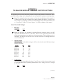
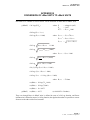
1
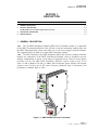
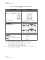
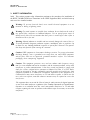
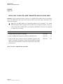
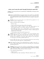
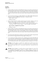
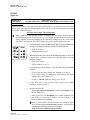
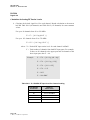
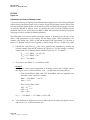
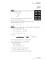
TM
Optiworx HWX 750 MHz
DFB Laser Transmitter
Procedures Manual
060675-001 Rev C
Procedures Manual
for
750 MHz HWX DFB Laser Transmitter
Optiworx HWX 750 MHz DFB Laser Transmitter
C-COR.net Document Number: 060675-001, Revision C
Copyright © 2001 C-COR.net Corp. All rights reserved.
Trademarks
C-COR, C-COR Electronics, DV6000, FlexNet, I-Flex, LITEAMP, and SMART-NETT are registered trademarks and Cable Network Manager, CNM, COR-Convergence, COR-Connect, FlexNode, lumaCOR, naviCOR,
Transfer Linearization, and TL Technology are trademarks of C-COR.net Corp. All other brand and product
names are trademarks or registered trademarks of their respective companies.
Contents and specifications within this manual are subject to change without notice.
Contacting C-COR.net Technical Support
Contact Information
You can contact C-COR.net by phone, e-mail, Internet, fax, or mail. When contacting C-COR.net
Technical Support, please be prepared to provide the information listed below:
•
Your company name and address
•
Your phone and fax number
•
Your e-mail address
•
The system site
•
A description of the problem(s) you are experiencing
•
Any equipment part/model numbers related to your specific problem(s)
•
The best way to contact you (phone, fax, e-mail, or mail)
•
The best time to contact you
Phone
Call the C-COR.net worldwide headquarters 24 hours a day, 7 days a week on the
C-COR.net Technical Support Hotline:
Technical Support Hotline: 888-827-2267
Or, call C-COR.net worldwide headquarters Monday through Friday (8 AM to 5 PM ET [+5GMT]) and
ask for the Applications Engineering and Training Department:
State College Office: +1-814-231-4422
Toll Free:
800-233-2267
E-Mail
Send an e-mail including the contact information listed in Contact Information:
[email protected]
Internet
Visit us on the World Wide Web at:
http://www.c-cor.net
From the C-COR.net home page, you can:
•
Submit your problem or Technical Publication request electronically;
(Services > Technical Support > Technical Support Form)
or
•
Download a product manual (if currently available);
(Services > Technical Support > Technical Documentation)
Fax
Send a fax with a cover sheet including the information listed in Contact Information.
814-237-5831
Page v
© 2001, C-COR.net Corporation
Mail
Send your letter including the information listed in Contact Information:
Attn: Applications Engineering and Training Department
C-COR.net Corp.
60 Decibel Road
State College, PA 16801-7580 USA
Providing Feedback on this Publication
C-COR.net welcomes your suggestions and assistance in identifying any errors, inaccuracies, or
misleading information. Please contact our Technical Publications Department with an e-mail
referencing the document number and page number(s) to which the feedback applies.
Send your e-mail to:
[email protected]
Page vi
© 2001, C-COR.net Corporation
ABOUT THIS MANUAL
This manual is written to provide a system engineer/technician with information to install and operate
the HWX 750 MHz Laser Transmitter, one of the components of the Optiworx HWX Headend
Transmission Platform.
Revision History
REVISION
DATE
REASON FOR CHANGE
A
B
10/96
3/00
C
12/01
Original Release
Update to Corporate format; update Specification Tables; add drive level calculations for
composite analog and digital carriers; add torque wrench requirement for RF cabling.
Trademark Update
Related Publications
Listed below are several related manuals that may be useful to users of this one. Copies of these
publications can be ordered by contacting your sales representative.
Title/Description
Part Number
HWX Equipment Shelf and Power Supply/Controller Installation and
Operation Manual
Contains information required for installation and operation of the HWX
Equipment Shelf (HX1281EC) and the Power Supply/Controller
Modules (HX1481PC or HX3481PC) used in that shelf.
060674-001
HWX Equipment Shelf and Power Supply/Controller Installation and
Operation Manual
Contains information required for installation and operation of the HWX
Equipment Shelf (HX2281EC) and the Power Supply/Controller
Modules (HX3481PC or HX1AC1PC) used in that shelf.
1074320
HWX 870 MHz DFB Laser Transmitter Installation and Operation Manual 060676-001
Contains information required for installation and operation of the HWX 870
MHz DFB Laser Transmitter Module in an HWX equipment shelf.
HWX 1550 nm EDFA Optical Amplifier Installation and User Instruction
Manual
Contains information required for installation and operation of HWX EDFA
Amplifier Module in an HWX equipment shelf.
1031384
HWX 1550 nm Transmitter Installation and User Instruction Manual
Contains information required for installation and operation of an HWX
1550 nm Transmitter Module in an HWX equipment shelf.
1031385
Page vii
© 2001, C-COR.net Corporation
Title/Description
Part Number
Optiworx HWX Control Panel Software User Guide
A Windows™ based Craft software program for accessing equipment
modules installed in an HWX equipment shelf.
1025580
Smart-Nett™ User’s Manual (DV and Optiworx Products)
A DOS software program designed for remote network management.
Contains information required for monitoring of operating parameters,
remote control of certain operating options, and alarm reporting of Optiworx
equipment units.
060919-001
OSWorx™ Commander Operating Guide
A Unix based software program designed for remote network management.
Contains information required for monitoring of operating parameters,
remote control of certain operating options, and alarm reporting of
Optiworx equipment units.
1025530
Page viii
© 2001, C-COR.net Corporation
Admonishments
Important safety admonishments are used throughout this manual to warn of possible hazards to
persons or equipment. An admonishment identifies a possible hazard and then explains what may
happen if the hazard is not avoided. The admonishments — in the form of Dangers, Warnings, and
Cautions — must be followed at all times. These warnings are flagged by use of the triangular alert
icon (seen below), and are listed in descending order of severity of injury or damage and likelihood of
occurrence.
Danger: Danger is used to indicate the presence of a hazard that will cause severe
personal injury, death, or substantial property damage if the hazard is not avoided.
Warning: Warning is used to indicate the presence of a hazard that can cause severe
personal injury, death, or substantial property damage if the hazard is not avoided.
Caution: Caution is used to indicate the presence of a hazard that will or can cause
minor personal injury or property damage if the hazard is not avoided.
General Safety Precautions
This equipment conforms to the requirements of a Class I laser product as defined in the US
Department of Health and Human Services, Bureau of Radiological Health Regulation 21 CFR
Subchapter J.
While Class I radiation levels are not exceeded when equipment components are handled per
instructions, enough invisible infrared energy is emitted from the end of an active fiber to damage the
retina of the eye. To avoid potentially dangerous laser radiation, follow the operating and
servicing procedures set forth in this manual in the sequences specified. DANGER labels on the
equipment alert users to the potential for exposure to hazardous amounts of invisible radiation.
Warning: DO NOT look into an amplifier’s/transmitter’s optical bulkhead receptacle or
an active fiber end emanating from an amplifier/transmitter. DO NOT look at an optical
fiber that is connected to an operating amplifier/transmitter but not connected to a
receiver or customer’s network. There may be no visible indication of light, but invisible
radiation can seriously damage the retina of the eye. Immediately place a cap or hood over
any radiating bulkhead receptacle or connector to avoid potentially dangerous radiation
exposure. In addition to helping prevent injury, capping connectors also keeps dirt
particles from entering them. C-COR.net also strongly recommends that you turn optical
amplifiers off before performing fusion splicing.
Caution: This equipment is electrostatic discharge sensitive. To prevent electrostatic
discharge damage, wear a grounded wrist strap when you touch an equipment unit.
Always place units on an approved, grounded antistatic surface. Use antistatic
packaging material when transporting equipment.
Page ix
© 2001, C-COR.net Corporation
FCC Compliance Statement
Warning: This equipment generates, uses, and can radiate radio frequency energy
and if not installed and used in accordance with the instruction manual, may cause
interference to radio communications. It is in the process of being tested for compliance
with limits for a Class A digital device pursuant to Subpart B of Part 15 of FCC Rules,
which are designed to provide reasonable protection against such interference when
operated in a commercial environment. Operation of this equipment in a residential
area is likely to cause interference to TV and radio reception in which case the user,
at their own expense, will be required to take whatever measures may be required to
correct the interference.
This equipment will be tested to ensure that it will not exceed Class A limits for radio
emission for digital apparatus, set out in the radio interference regulation of the
authorization methods of Industry Canada. Operation in a residential area may cause
unacceptable interference to TV and radio reception requiring the owner or operator
to take whatever steps are necessary to correct the interference.
HWX Applicable Standards Compliance Matrix
COUNTRY/TYPE
STANDARD
Safety
US
Canada
European Union
Australia
Japan
UL-1950
CSA C22.2 No. 950-M89
EN-60950
AS-3260
IEC-950
EMI
US
Canada
European Union
Germany
Australia
Japan
FCC Part 15, Subpart B, Class A
Recognizes FCC
EN55022-B
VDE 0871/0875
AS-3548-1992
VCC-1
EMC
European Union
Page x
© 2001, C-COR.net Corporation
EN50052
TABLE OF CONTENTS
Content
Page
SECTION 1
DESCRIPTION
1.
GENERAL DESCRIPTION
1-1
2.
PHYSICAL DESCRIPTION
1-3
750 MHz DFB Laser Transmitter Quick Reference Guide
1-4
3.
FUNCTIONAL DESCRIPTION
1-6
4.
SPECIFICATIONS
1-7
SECTION 2
INSTALLATION
1.
GENERAL
2-1
2.
HOW TO USE THIS SECTION
2-1
3.
SAFETY INFORMATION
2-2
INSTALLATION TASK INDEX LIST
2-3
TOP PROCEDURES
2-4
APPENDIX A. 750 MHz DFB MODULE FIRMWARE FACTORY SETTINGS
APPENDIX B. CONVERSION OF dBm UNITS TO dBmV UNITS
Page xi
© 2001, C-COR.net Corporation
(This page intentionally left blank.)
Page xii
© 2001, C-COR.net Corporation
PN 060675-001
Revision C, December 2001
SECTION 1
DESCRIPTION
Content
Page
1.
GENERAL DESCRIPTION . . . . . . . . . . . . . . . . . . . . . . . . . . . . . . . . . . . . . . . . . . . . . . . . . . . . . . . . . . . . . . . . . . . . 1-1
2.
PHYSICAL DESCRIPTION . . . . . . . . . . . . . . . . . . . . . . . . . . . . . . . . . . . . . . . . . . . . . . . . . . . . . . . . . . . . . . . . . . . . 1-3
3.
FUNCTIONAL DESCRIPTION . . . . . . . . . . . . . . . . . . . . . . . . . . . . . . . . . . . . . . . . . . . . . . . . . . . . . . . . . . . . . . . . 1-6
4.
SPECIFICATIONS . . . . . . . . . . . . . . . . . . . . . . . . . . . . . . . . . . . . . . . . . . . . . . . . . . . . . . . . . . . . . . . . . . . . . . . . . . . 1-7
750 MHz DFB Laser Transmitter Quick Reference Guide . . . . . . . . . . . . . . . . . . . . . . . . . . . . . . . . . . . . . . . . . 1-4
1. GENERAL DESCRIPTION
1.01 The 750 MHz Distributed Feedback (DFB) Laser Transmitter module is a component
of the HWX Transmission Platform. This efficient, low-power transmitter module plugs into
the HWX Equipment Shelf, along with either one or two Power Supply/Controller modules.
The equipment shelf can hold up to eight DFB Transmitter modules.
1.02 The DFB Transmitter, the HWX Equipment Shelf, and the Power Supply/Controller
modules are components of the HWX Transmission Platform, which is designed to provide
multiple configurations to satisfy a wide range of application needs. There are many options
available for the 750 MHz DFB Transmitter Module: optical output power levels
from 2.5 mW (4 dBm) to 20 mW (13 dBm), dual front-panel optical outputs with integral
splitters from 50/50 to 90/10, RF input isolation (standard, high or enhanced), and
performance (standard, high or ultra).
Figure 1-1. HWX 750 MHz DFB Laser Transmitter
Page 1-1
© 2001, C-COR.net Corporation
PN 060675-001
Revision C, December 2001
1.03 The 750 MHz Distributed-FeedBack (DFB) Laser Transmitter Module accepts two
broadband RF inputs within the frequency range of 50-750 MHz. The two inputs can be used to
combine blocks of channels from different sources (i.e. 50-250/250-550 or 50-550/550-750) to
accommodate up to 112 NTSC channels. The two RF inputs are isolated from each other by at
least 20 dB. The ideal RF input level is approximately 17 dBmV/carrier unmodulated with an
80 channel load, and 15.5 dBmV/carrier unmodulated with a 112 channel load. The modules
provide an optical output at the front panel, with dual outputs (integral splitter) as an option.
1.04 The HWX Transmission Platform provides maximum bandwidth granularity and
efficient use of headend space when configured with Distributed-FeedBack (DFB) Transmitter
Modules. One DFB Transmitter Module with an optical splitter can serve several optical nodes.
A combination of numerous DFB Transmitters and optical splitters may achieve levels of
bandwidth granularity from 12.5 MHz to 200 MHz of targeted services bandwidth per node.
1.05 Figure 1-2 depicts one of the many possible configurations for the HWX Transmission
Platform using 750 MHz DFB Transmitter modules. This particular HWX application provides
200 MHz of targeted services bandwidth at a granularity of 50 MHz per node for targeted
services in addition to the normal forward path 50 - 550 MHz. Figure 1-3 shows a configuration
which allows 200 MHz of bandwidth for targeted services at a granularity of 200 MHz per
node.
Figure 1-2. HWX Transmission Platform Configured with 750 MHz DFB Transmitter
Module for 200 MHz Bandwidth at 50 MHz per Node for Targeted Services
Figure 1-3. HWX Transmission Platform Configured with 750 MHz DFB Transmitter
Module for 200 MHz Bandwidth at 200 MHz per Node for Targeted Services
Page 1-2
© 2001, C-COR.net Corporation
PN 060675-001
Revision C, December 2001
2. PHYSICAL DESCRIPTION
2.01 The direct-modulated DFB laser module (Figure 1-1) is a plug-in module designed
exclusively for the HWX Transmission Platform. The DFB Transmitter module measures
1.67”W x 6.65”H x 9.33”D and weighs approximately 4 pounds. The circuitry is
completely enclosed in a metal housing with a heat sink mounted on the left side of the
module to aid in the dissipation of heat. The DFB Transmitter is designed to operate at
temperatures from 0oC to +50oC with non-condensing relative humidity of 10 to 90%. Up to
eight DFB modules can be installed in a single shelf.
2.02 All power and control connections to the DFB Transmitter module are made through the
backplane connector, through the HWX Power Supply/Controller module. RF and optical signal
connections are made directly to the module. The RF connectors on the back of the module extend
through an opening in the back of the HWX equipment shelf to providing full access when the
module is installed in the shelf.
Note: The 750 MHz DFB Laser Transmitter modules can be installed in any model
HWX Equipment Shelf equipped with an HWX Power Supply/Controller, except for
earlier model shelves (HX1281ES) and controllers (HX2481PC) which are not equipped
to support these modules.
2.03 The 750 MHz DFB Laser Transmitter front panel contains the LED status indicators,
optical output connectors, and the RF input monitor test point which are located on the upper
portion of the module front panel. The optical output connectors are located on the lower,
angled portion of the front panel of the transmitter module. The number of optical output
connectors is based on the “Optical Output” option selected when the module is ordered from
the factory. Optical Output Option 1 provides only one output connector (top connector) and
the bottom port location is covered with a blank plate. Split Output Options have an internal splitter
that feeds two output connectors. The top most connector will always be the port with the higher
output level from the splitter.
2.04 A Quick Reference Guide (see Figure 1-4 on the next page) has been provided to
facilitate location of information on each of the 750 MHz DFB Laser Transmitter module’s
LED indicators and connectors. The Quick Reference Guide has reference labels for these items
that indicate the appropriate page number where pertinent information can be obtained. Table 1-1,
“HWX 750 MHz DFB Laser Transmitter Front Panel Indicators, Connectors, and Test Points”, also
provides information on all of the front panel items.
2.05 All power and control connections to the 750 MHz DFB Laser Transmitter module are
made through the equipment shelf backplane motherboard connector, from the HWX Power
Supply/Controller module.
2.06 On the rear panel of the module is the RF input, F-type, connector and a DIN style edge
connector (48 pin socket) which are both mounted on the module’s printed circuit board. The
edge connector mates with the equipment shelf’s internal motherboard connectors. The RF
input is connected at the rear of the transmitter module, through an opening in the back of the
HWX equipment shelf.
Page 1-3
© 2001, C-COR.net Corporation
PN 060675-001
Revision C, December 2001
750 MHz DFB LASER TRANSMITTER QUICK REFERENCE GUIDE
“Thumb” screw
for installing or
removing the
module
RF INPUT
connectors
(Rear Panel)
Pg. 1-2, 3, 5
RF INPUT
MONITOR
Test Point
Pg. 1-5
ALARM LED
(Logical “OR”)
Green = OK
Red = Alarm
RF INPUT LED
(Logical “OR”)
Pg. 1-5
Green = Low
Off
= OK
Red = High
Pg. 1-5
LASER POWER
LED
Green = Laser ON
Off = Laser OFF
Pg. 1-5
Equipment Shelf
connector
(Rear Panel)
OPT OUT
Optical Output
connectors
Pg. 1-3
Pg. 1-3, 5
Figure 1-4. HWX 750 MHz DFB Laser Transmitter Quick Reference Guide
Page 1-4
© 2001, C-COR.net Corporation
PN 060675-001
Revision C, December 2001
Table 1-1. HWX 750 MHz DFB Laser Transmitter Front Panel Indicators, Connectors, and
Test Points
TYPE
ITEM NAME
FUNCTION
F
RF INPUT
MONITOR
75-ohm connection point for monitoring the incoming RF signal.
Signal strength is –20 dB relevant to the RF input ports.
LED
(green/red)
ALARM
GREEN when no alarm conditions exist.
RED when any of the following alarm conditions exists in this
module:
Major Alarm:
Optical Output - power outside high/low threshold setting, when
laser control is on.
RF DriveNote1- RF input is above the high threshold setting.
Minor Alarm:
TemperatureNote2- Laser temperature outside high/low threshold
setting
Laser Current outside high/low threshold setting, when laser control
is on.
TE Current outside of high/low threshold setting.
LED
(green/off)
LASER
POWER
GREEN when laser light present at the optical output.
OFF when laser is off (deactivated).
LED
(green/red/off)
RF INPUT
RED when the RF input level is high,
GREEN when level is low.
OFF when the RF level is in range.
FC Bulkhead
OPT OUT Standard: FC/APC bulkhead connector.
(1 or 2)Note3 Options: SC/APC, Ultra FC/PC, Ultra SC/PC
Note 1. All HWX 750 MHz DFB Laser Transmitter modules are shipped from the factory with the “low” RF input alarms disabled (off).
Note 2. Factory set. The alarm threshold levels can not be changed.
Note 3. Based on Optical Output Option selected (single DTx1, or split output DTx2-6 options, see Figure 1-5).
Part
Number
DT-x1
DT-x2
DT-x3
DT-x4
DT-x5
DT-x6
Internal Splitter
Ratio Options
Connector
(top) (bottom)
100
no conn
50
50
60
40
70
30
80
20
90
10
Figure 1-5. Optical Output Splitter Options
Page 1-5
© 2001, C-COR.net Corporation
PN 060675-001
Revision C, December 2001
3. FUNCTIONAL DESCRIPTION
3.01 The HWX 750 MHz DFB Laser Transmitter Module accepts two RF inputs within the
frequency range of 50 to 750 MHz. There is a minimum of -20 dB of isolation between the
inputs which allows great flexibility in the input frequency spectrum. The inputs may come
from divergent locations to combine for distribution to an optical node, or the frequency may be
reserved for expansion into targeted future services. Figure 1-6 is a simplified block diagram
of the 750 MHz DFB Laser Transmitter.
Option
DT-x1
DT-x2
DT-x3
DT-x4
DT-x5
DT-x6
Internal Splitter
Ratio Options
Connector
(2)
(3)
100
no conn
50
50
60
40
70
30
80
20
90
10
Figure 1-6. HWX 750 MHz DFB Laser Transmitter Simplified Block Diagram
3.02 To allow the greatest degree of flexibility, there is no filtering of the input in the
transmitter module. The RF inputs are combined using a conventional RF wideband
transformer. The combined RF signal is then applied to a 15 dB. preamplifier. The output of
the preamplifier stage is routed to a directional coupler. The output (low-loss leg) of the
directional coupler is connected to the microprocessor-controlled AGC circuit, and the
directional coupler tap (at -20 dB) is routed to the front-panel RF INPUT MONITOR test point.
3.03 The AGC circuit can operate in either of two different modes: factory set AGC (which
is set during testing for optimal output), or user adjustable AGC (which allows the user to reset
the AGC setpoint by ±3 dB in 1 dB increments). In the factory set AGC mode, the AGC circuit
can handle variations on the input of ±3 dB. In the user adjustable AGC mode, the AGC circuit
will also handle variations on the input of ±3 dB up to the absolute limits of the card. The AGC
circuit also can be disabled to operate the transmitter in a Fixed Gain mode. All of these modes
can be chosen and adjusted through the local Control Panel software.
3.04 The signal level of the output of the directional coupler is detected and monitored by the
microprocessor, which uses it to control the PIN-diode attenuator which provides the AGC
function. From the PIN-diode the signal is processed by the DFB Laser Drive circuitry where
it is amplified, compensated for distortions caused by the laser diode and used to drive the
laser diode. The composite signal is output to a single connector, as an intensity modulated
optical signal. If an optional integrated optical splitter on the output is ordered, the power available
on each output connector will decrease based on the option selected (refer to Figure 1-5).
Page 1-6
© 2001, C-COR.net Corporation
PN 060675-001
Revision C, December 2001
4. SPECIFICATIONS
4.01 The 750 MHz DFB Laser Transmitter module has many specification options
available: optical output power levels between 2.5 mW (4 dBm) and 20 mW (13 dBm), dual
front-panel optical outputs with integral splitters from 50/50 to 90/10, RF isolation (standard, high or
enhanced), and performance levels (standard, high and ultra). Below is a breakdown of the part
number and its associated options:
HX7L xx DT x x x x
Optical output connector type
RF input isolation
Number of Optical output connectors
and integral splitter ratio
Performance level
Minimum optical output power
4.02 Table 1-2 provides the specifications for the HWX 750 MHz DFB Laser Transmitter
module.
Note: Specifications listed here are current as of the date of publication of this
manual. C-COR.net reserves the right to change specifications without prior notice. You
may verify the product specifications by contacting Sales or Customer Service.
Table 1-2. HWX 750 MHz DFB Laser Transmitter Specifications
CHARACTERISTIC
SPECIFICATION
PHYSICAL
Form Factor
Single HWX module width
Dimensions
Weight
1.7” W x 6.7” H x 9.3” D
approx. 4 lbs.
POWER
+24 VDC, ±12 VDC, and GND
Input Voltages
Power Consumption
20 W max.
RF INPUT
RF Bandwidth
RF input level (per carrier, unmodulated)Note 1
50 - 750 MHz
80 Channels
112 Channels
RF Input Isolation
Return Loss
AGC Control Range
RF input impedance (at rear panel connector)
RF Monitor (front panel test point)
+17 dBmV/Ch
+15.5 dBmV/Ch
20 dB min.
-16 dB min.
±3 dB
75 Ohms
-20 dB (±1.0 dB)
relative to RF INPUT port
(continued)
Page 1-7
© 2001, C-COR.net Corporation
PN 060675-001
Revision C, December 2001
Table 1-2. HWX 750 MHz DFB Laser Transmitter Specifications
(continued)
CHARACTERISTIC
SPECIFICATION
OPTICAL OUTPUTs
Optical Wavelength
Output Power Level (minimum)
Model P/N
1310 nm +45/-20 nm
HX-7L04-DT
HX-7L06-DT
HX-7L08-DT
HX-7L09-DT
HX-7L10-DT
HX-7L11-DT
HX-7L12-DT
HX-7L13-DT
Optical ConnectorsNote 2
PERFORMANCE
Rf Performance SpecificationsNotes 3, 4
(unmodulated carriers)
4 dBm (2.5 mW)
6 dBm (4.0 mW)
8 dBm (6.3 mW)
9 dBm (7.9 mW)
10 dBm (10.0 mW)
11 dBm (12.5 mW)
12 dBm (16.0 mW)
13 dBm (20.0 mW)
FC/APC (standard), SC/APC, Ultra FC/PC
and Ultra SC/PC
Option
Standard:
High:
Ultra:
Option
Standard:
High:
Ultra:
ENVIRONMENTAL
Temperature:
Storage Range
Operating Temperature Range
Humidity (relative humidity, non-condensing) :
Storage
Operating
Note 1.
Note 2.
Note 3.
Note 4.
80 Channels
DT- CSO
CTB
CNR
1 -63 dBc -66 dBc 52.5 dBc
A -64 dBc -67 dBc 54.0 dBc
C -64 dBc -67 dBc 55.0 dBc
112 Channels
DT- CSO
CTB
CNR
2 -62 dBc -66 dBc 50.5 dBc
B -64 dBc -67 dBc 52.0 dBc
D -64 dBc -67 dBc 53.0 dBc
-40°C to +80°C
0°C to +50°C
10 to 95%
10 to 90%
For channel loading comprised of a combination of analog and digital signals, the correct composite RF drive
level into the transmitter can be calculated by using DLP-504.
Some performance degradation may occur when connectors other than APC type are used.
HX-7L10-DT degrades by 0.5 dB in CNR for performance specs “A”, “B”, “C” and “D”.
HX-7L11-DT degrades by 1.0 dB in CNR for performance specs “A”, “B”, “C” and “D”.
HX-7L12-DT degrades by 0.5 dB in CNR for performance specs “1”.
HX-7L13-DT degrades by 1.0 dB in CNR for performance specs “1”.
HX-7L12-DT degrades by 0.5 dB in CNR for performance specs “2”.
The above specifications are for the transmitter, fiber, and detector only. Receiver post amplifier and system
noise are not included in the CNR numbers.
Page 1-8
© 2001, C-COR.net Corporation
PN 060675-001
Revision C, December 2001
SECTION 2
INSTALLATION
Content
Page
1.
GENERAL . . . . . . . . . . . . . . . . . . . . . . . . . . . . . . . . . . . . . . . . . . . . . . . . . . . . . . . . . . . . . . . . . . . . . . . . . . . . . . . . . 2-1
2.
HOW TO USE THIS SECTION . . . . . . . . . . . . . . . . . . . . . . . . . . . . . . . . . . . . . . . . . . . . . . . . . . . . . . . . . . . . . . . . . 2-1
3.
SAFETY INFORMATION . . . . . . . . . . . . . . . . . . . . . . . . . . . . . . . . . . . . . . . . . . . . . . . . . . . . . . . . . . . . . . . . . . . . . 2-2
INSTALLATION TASK INDEX LIST . . . . . . . . . . . . . . . . . . . . . . . . . . . . . . . . . . . . . . . . . . . . . . . . . . . . . . . . . . . . . . . . . 2-3
TOP PROCEDURES . . . . . . . . . . . . . . . . . . . . . . . . . . . . . . . . . . . . . . . . . . . . . . . . . . . . . . . . . . . . . . . . . . . . . . . . . . . . . 2-4
1. GENERAL
1.01 This section presents the procedures for unpacking and installation of the HWX
750 MHz DFB Laser Transmitter in the HWX Equipment Shelf, cleaning of the fiber optic cable
connectors and receptacles, RF and optical cable connections, and initial turn-up and test of
the installed module.
2. HOW TO USE THIS SECTION
2.01 The procedures in this section are written in the Task Oriented Practice (TOP) format.
TOP procedures are step-by-step instructions for completing indicated tasks. To find instructions
for installing the HWX 750 MHz DFB Laser Transmitter proceed as follows:
1.
Find the task to be performed in the Installation Task Index List (IXL-001).
2.
Locate the procedure for the task. Each procedure in this manual is one of the following
types:
a) Non Trouble clearing Procedure (NTP) - Directive level procedure listing normal
work items to be performed.
b) Detail Level Procedure (DLP) - Detailed step-by-step instructions.
3.
Perform all the items in the NTP in the order listed unless you are sent to another NTP.
When you finish an NTP, you have completed the task. For more detailed information,
you may be referred from the NTP to a detailed level procedure (DLP-xxx). Detail
Level Procedures may also direct you to other Detail Level Procedures.
Note: If one NTP sends you to another, in most cases you need not return to the first
NTP after finishing the second.
Note: When you complete a DLP, return to the procedure which sent you to the justcompleted DLP.
Page 2-1
© 2001, C-COR.net Corporation
PN 060675-001
Revision C, December 2001
3. SAFETY INFORMATION
3.01 This section presents safety information pertinent to the procedures for installation of
the HWX 750 MHz DFB Laser Transmitter in the HWX Equipment Shelf, and initial turn-up
and test of the installed module.
Warning: To prevent electrical shock, never install electrical equipment in a wet
location or during a lightning storm.
Warning: To avoid exposure to invisible laser radiation, do not look into the ends of
any optical fiber connectors or bulkhead adapters. Use an optical power meter to
identify active fibers. Do not assume that laser power is turned off or that a fiber is
disconnected at its far end.
Warning: Infrared radiation is invisible and can seriously damage the retina of the eye.
To avoid potentially dangerous radiation exposure, immediately place a protective cap
or hood over any radiating bulkhead receptacle or optical fiber connector. This practice
also keeps dirt particles from entering the connector.
Caution: HWX equipment is electrostatic discharge sensitive. To prevent electrostatic
discharge damage, wear a grounded wrist strap when you touch HWX equipment.
Always place units on an approved, grounded antistatic surface. Use antistatic
packaging when transporting equipment.
Caution: This equipment generates, uses, and can radiate radio frequency energy
and if it is not installed and used in accordance with the instruction manual, it may cause
interference to radio communications. It has been tested and found to comply with
limits for a Class A digital device pursuant to Subpart B of Part 15 of FCC Rules,
which are designed to provide reasonable protection against such interference from
equipment operated in a commercial environment. Operation of this equipment in a
residential area may cause interference to TV and radio reception, in which case the
user, at his own expense, must take whatever measures may be required to correct the
interference.
This equipment does not exceed the Class A limits for radio emission for digital apparatus
set out in the radio interference regulations of the Canadian Department of Communications.
Operation in a residential area may cause unacceptable interference to TV and radio
reception, requiring the owner or operator to take whatever steps are necessary to correct the
interference.
Page 2-2
© 2001, C-COR.net Corporation
PN 060675-001
Revision C, December 2001
IXL-001
Page 1 of 1
INSTALLATION TASK INDEX LIST
Find Your Job in the List Below
Then Go To:
Pg:
INSTALL HWX 750 MHZ DFB LASER TRANSMITTER ........................ NTP-002 ........................ 2-4
MODULE IN HWX SHELF
Unpack Equipment and Inspect for Damage .................................. DLP-500 .................... 2-6
Install HWX 750 MHz DFB Laser Transmitter Module .................... DLP-501 .................... 2-7
in HWX Shelf
Cleaning and Mating Instructions for Fiber Optic .......................... DLP-502 .................. 2-10
Connectors and Adapters (SC and FC)
INITIAL TURN-UP AND TEST ............................................................... NTP-003 ........................ 2-5
Perform Initial Functional Check of HWX 750 MHz DFB ................ DLP-503 .................. 2-15
Laser Transmitter Module
Check and Adjust RF Carrier Input Signals ................................... DLP-504 .................. 2-21
Page 2-3
© 2001, C-COR.net Corporation
PN 060675-001
Revision C, December 2001
NTP-002
Page 1 of 1
INSTALL HWX 750 MHz DFB LASER TRANSMITTER MODULE IN HWX SHELF
Summary: This procedure describes insertion of 750 MHz DFB modules into the equipment
slots of an HWX shelf, fiber optic cable output and RF coaxial-cable input connections to the
Transmitter modules.
Note: The 750 MHz DFB Laser Transmitter modules can be installed in any model
HWX Equipment Shelf equipped with an HWX Power Supply/Controller, except for
earlier model shelves (HX1281ES) and controllers (HX2481PC) which are not equipped
to support these modules.
Do Items Below in the Order Listed
For Details Go To:
Pg:
1. Unpack module and inspect for damage.
DLP-500
2-6
2. Install 750 MHz DFB Transmitter modules in the HWX shelf.
DLP-501
2-7
3. Clean the fiber optic connectors and any bulkhead receptacles (SC
and FC) suspected of being dirty. Connect the coaxial RF input signal
cables to the shelf backplane. Connect the outgoing fiber optic cables
to the network.
DLP-502
2-10
Stop! You have completed this procedure.
Page 2-4
© 2001, C-COR.net Corporation
PN 060675-001
Revision C, December 2001
NTP-003
Page 1 of 1
INITIAL TURN-UP AND TEST
Summary: Turn-up and test procedures for the HWX 750 MHz DFB Laser Transmitter
module consist of the following:
Do Items Below in the Order Listed
For Details Go To:
Pg:
1. Check front panel LED indications on the 750 MHz DFB
Transmitter modules.
DLP-503
2-15
• Check RF input signals to the shelf for appropriate levels
and flatness.
DLP-504
2-21
Stop! You have completed this procedure.
Page 2-5
© 2001, C-COR.net Corporation
PN 060675-001
Revision C, December 2001
DLP-500
Page 1 of 1
UNPACK EQUIPMENT AND INSPECT FOR DAMAGE
Summary: Open and inspect shipping boxes. Verify that all parts have been received, and that
no shipping damage has occurred.
1.
Obtain the following tools and equipment to unpack the equipment:
• ESD wrist strap
• ESD antistatic mat
• Box cutter
Caution: Electronic equipment can be damaged by static electrical discharge. When
handling HWX-shelf units, always follow Electrostatic Discharge (ESD) protection
practices. Wear a grounded wrist strap when you touch a unit. Use antistatic
packaging when transporting or storing units. When working on a unit, always place
it on an approved, electrically grounded antistatic mat.
2.
Place the ESD wrist strap on your wrist and snap the ground wire to the wrist strap
connection. Plug the ground plug into a grounded ESD jack.
3.
Examine the outside of the shipping carton for tears, dents, punctures, etc., that could
indicate possible shipping damage. If shipping damage is found, contact Technical Support.
Refer to “Contacting C-COR.net Technical Support” in the Front Matter of this manual.
4.
Open the shipping cartons and carefully unpack the equipment. Do not discard the packing
materials at this time.
5.
Check each component against the packing list to make sure that the correct catalog numbers
and quantities were received. Note any discrepancies.
6.
Carefully inspect each item for damage. Check for detached, broken or bent parts, damaged
connectors, bent connector pins, and any other physical damage to the unit. Do not install
any product that is significantly damaged.
7.
If there is any damage to the equipment, contact Technical Support. Refer to “Contacting
C-COR.net Technical Support” in the Front Matter of this manual.
8.
If the product is undamaged and all components are accounted for, discard packing material
if desired. You may still want to save some original shipping cartons and packing materials
for reuse should it become necessary to return any equipment.
Stop! You have completed this procedure.
Page 2-6
© 2001, C-COR.net Corporation
PN 060675-001
Revision C, December 2001
DLP-501
Page 1 of 3
INSTALL HWX 750 MHz DFB LASER TRANSMITTER MODULE IN HWX SHELF
Summary: This procedure describes how to install the HWX 750 MHz DFB Laser Transmitter module
in an HWX shelf.
Note: The 750 MHz DFB Laser Transmitter modules can be installed in any model HWX
Equipment Shelf equipped with an HWX Power Supply/Controller, except for earlier model
shelves (HX1281ES) and controllers (HX2481PC) which are not equipped to support these
modules.
Warning: To prevent electrical shock, never install electrical equipment in a wet
location or during a lightning storm.
1.
Obtain the following tools and equipment:
• ESD wrist strap
• Torque wrench (20 inch-pounds setting), for RF cable installation
• Protective caps or plugs as needed to cover fiber optic connectors and
optical bulkhead receptacles for all modules installed in the HWX shelf
• HX1281BM blank module covers (use HX1281BP for a Power Supply/Controller
slot) for any HWX shelf slot not to be occupied by a module, to ensure proper heat
dissipation and minimize EMI
• 75 Ohm terminator, required if only one RF input port is used
Caution: Electronic equipment can be damaged by static electrical discharge. When
handling HWX-shelf units, always follow Electrostatic Discharge (ESD) protection
practices. Wear a grounded wrist strap when you touch a unit. Use antistatic
packaging when transporting or storing units. When working on a unit, always place
it on an approved, electrically grounded antistatic mat.
2.
Place the ESD wrist strap on your wrist and snap the ground wire to the wrist strap
connection. Plug the ground plug into a grounded ESD jack.
Note: Although not required, when installing HWX plug-in modules in the shelf, it is
easiest to begin loading modules at the left end of the shelf (slot 1), then proceed
toward the right (slot 8).
Warning: Do not use excessive force inserting or reseating modules in the equipment
shelf. Although all modules can be removed or installed while the shelf is powered (hot
swap) without risk of damage or system interruption, excessive insertion force (slamming
module into shelf while inserting) could cause system interruption.
3.
Is the equipment shelf powered-up?
• If No, go to step 7.
• If Yes, perform step 4 while monitoring for LED status indicated in step 5.
Page 2-7
© 2001, C-COR.net Corporation
PN 060675-001
Revision C, December 2001
DLP-501
Page 2 of 3
4.
Slide the module into the slots of the HWX shelf, taking care to insert the top and bottom of
the left edge of the module’s chassis in the guides provided in the shelf’s module compartment.
The 48 pin DIN connector at the rear of the module will mate with the shelf’s backplane
connector when the module is fully inserted (top of module front panel flush against top shelf
rail).
5.
Upon insertion the transmitter ALARM, RF INPUT, and LASER POWER LEDs should all
momentarily illuminate (LED test), then return to a steady-state status.
• If No, continue to step 6.
• If Yes, go to step 8.
6.
Remove (unseat) and then carefully reinstall (reseat) the module, making sure the rear
connector mates cleanly in the shelf. Did the LEDs momentarily illuminate?
• If No, the LEDs did not momentarily illuminate, contact Technical Support. Refer to
“Contacting C-COR.net Technical Support” in the Front Matter of this manual.
Stop! You have completed this procedure.
• If Yes, go to step 8.
7.
Slide the module into the slots of the HWX shelf, taking care to insert the top and bottom of
the left edge of the module’s chassis in the guides provided in the shelf’s module compartment.
The 48 pin DIN connector at the rear of the module will mate with the shelf’s backplane
connector when the module is fully inserted (top of module front panel flush against top shelf
rail).
8.
Press in the spring-loaded captive retaining screw at the top of the module’s front panel and
turn it clockwise to engage the threads. Finger tighten retaining screw.
9.
Cover unused Power Supply/Controller slots with blank panel assembly HX1281BP and
any unused module slots with blank panel assembly HX1281BM. Insert the tab at the bottom
of the assembly into the slot provided for it in the floor of the shelf’s module compartment.
Secure the blank panels in place with its spring-loaded captive retaining screw, as in step 8.
Warning: To avoid exposure to invisible laser radiation, do not look into the ends of
any optical fiber or bulkhead connector. Use an optical power meter to identify active
fibers. Do not assume laser power is turned off or that the fiber is disconnected at the
other end.
Warning: Infrared radiation is invisible and can seriously damage the retina of the
eye. To avoid potentially dangerous amounts of radiation exposure, a protective cap
or hood MUST be immediately placed over any radiating bulkhead receptacle or
optical fiber connector. This practice also keeps dirt particles from entering the
connector.
Page 2-8
© 2001, C-COR.net Corporation
PN 060675-001
Revision C, December 2001
DLP-501
Page 3 of 3
10.
If not already performed, clean all fiber optic connectors and bulkhead receptacles suspected
of being dirty per DLP-502.
11.
Dress each fiber optic output cable to give it a minimum 3-inch radius where it turns up to
connect to an optical bulkhead connector, and leave a 6-inch diameter
strain-relief loop in each cable, secure the cable in one of the anchor clips on the
equipment shelf’s optical organizer tray.
12.
Is the Transmitter’s optical output going to be connected at this time?
• If No, cap all fiber optic cable connectors and module bulkhead receptacles. Go to
step 14.
• If Yes, continue to step 13.
Note: If the transmitter has two optical bulkhead receptacles (OPT OUT) the output
power is split between the two connectors based on the module’s output selection option
(see Figure 1-5 on page 1-5).
13.
Connect a fiber optic cable to the transmitter’s OPT OUT receptacle (located on the
angled front panel portion of the module) to the optical output receptacle of the mating
unit or customer’s network. Repeat for the second OPT OUT receptacle if a second
connection is required.
Caution: It is recommended that a torque wrench be used to attach the RF cable to the
transmitter. Do not exceed 20 inch-pounds of torque when connecting the RF cable to the
module’s RF Input ports. Excessive force can damage the module’s RF connection.
14.
Connect the F-type receptacle on the rear of the transmitter module, passing the cable
through the cutout provided in the rear of the equipment shelf. Finger tighten RF cable,
then torque to 20 inch-pounds (additional 1/8 turn, if no torque wrench is available).
15.
If only one of the RF input ports is to be used, place a 75 Ohm terminator on the unused RF
input port.
Stop! You have completed this procedure.
Page 2-9
© 2001, C-COR.net Corporation
PN 060675-001
Revision C, December 2001
DLP-502
Page 1 of 5
CLEANING AND MATING INSTRUCTIONS FOR FIBER OPTIC
CONNECTORS AND ADAPTERS (SC AND FC)
Summary: Any contamination of the optical interface where one fiber mates with another can
severely degrade the performance of a fiber optic system. Thoroughly clean all connectors
and adapters before making up any connections.
1.
Required cleaning materials:
• Lint free laboratory wipes (Chemtronics Control Wipes or equivalent)
• Isopropyl alcohol, reagent grade (99.5% pure)
• Optical Fiber Connector Cleaner (lint-free microporous fabric on an enclosed reel with
use-once-and-advance shutter mechanism, Alcoa Fujikura Ltd PREP® FCC-02-R
or equivalent)
• Adapter Cleaner Tips (microporous fabric spiral-wrapped on end of thin plastic
handle, Alcoa Fujikura Ltd ACT-1® or equivalent)
2.
Recommended inspection device:
• Fiber inspection microscope (“fiberscope”—200X minimum magnification
microscope with integral illumination, such as Leica Fibervue 31-22-70 or Noyes
Fiber Systems OFS-300, with adapter required to position ferrule of connector type
in use)
Optimum signal transfer between fibers terminated in fiber optic connectors occurs
only if the fiber ends come together precisely aligned and with nothing between them
that can attenuate, refract, or reflect the lightwave. Fabrication techniques precisely
Figure 502-1. Fiberscope Inspection of a Fiber Optic Connector Ferrule
Page 2-10
© 2001, C-COR.net Corporation
PN 060675-001
Revision C, December 2001
DLP-502
Page 2 of 5
center each fiber and its cladding in the connector’s cylindrical ferrule. Each ferrule
endface is slightly domed (with the fiber at the apex of the dome) and highly polished.
The split sleeve in the adapter used to mate two connectors grips the two ferrules
snugly and keeps them aligned. Other mechanical features of connectors and adapters
hold the ferrule endfaces pressed together. But it is the installing technician’s
responsibility to see that endfaces are clean before they are joined. Figures 502-1 and
502-2 show why a fiberscope is the tool for that job.
Figure 502-2. Typical Ferrule Endface Contamination Visible Through a Fiberscope
Page 2-11
© 2001, C-COR.net Corporation
PN 060675-001
Revision C, December 2001
DLP-502
Page 3 of 5
Warning: Infrared radiation is invisible and can seriously damage the retina of the
eye. Be certain that no laser light is present on a fiber before cleaning its connector.
Do not assume that laser power is turned off, or that a fiber is disconnected at its other
end. Use an optical power meter if necessary to identify active fibers.
3. Cleaning procedure for:
a. Cable connectors, continue to step 4.
b. Module bulkhead receptacles, go to step 9.
Cable Connectors
4. To clean a connector, fold a clean, new wipe into a 2-inch square pad. Moisten (but do not
saturate) about a 1/2-inch diameter portion of the pad with alcohol. Wrap the moistened part
of the pad around the exposed ferrule end and—using firm finger pressure—twist the pad
around the ferrule in at least three back-and-forth quarter- to half-turn rotations. The pad
should squeak against the ferrule.
5. Press the ferrule endface into the wet spot on the wipe. Using firm force, twist the ferrule so
that a wiping action occurs. Repeat this twice, using a clean alcohol-moistened spot on the
pad each time. The pad should squeak against the ferrule.
6. Press the ferrule endface into a dry spot on the wipe and—using gentle force—twist the
ferrule so that a wiping action occurs. Discard the used pad.
7.
Visually inspect the ferrule endface for cleanliness. We strongly recommend use of a fiberscope
for this inspection.
• If fiberscope inspection shows that endface cleanliness meets the standard shown in
Figure 502-3, go to step 10 (FC type connector) or step 11 (SC type connector) for
connector mating instructions.
• If fiberscope inspection shows that the ferrule endface is not thoroughly clean, or if
no fiberscope is available, continue with step 8.
Caution: When performing step 8 on an angle
polished connector, tilt the connector until
the angled ferrule endface is parallel with the
cleaning tape. Then drag the ferrule surface
over the tape low side first, so that the sharper
high side of the ferrule does not snag in and
tear the tape fabric.
Page 2-12
© 2001, C-COR.net Corporation
PN 060675-001
Revision C, December 2001
DLP-502
Page 4 of 5
Figure 502-3. Inspection Standard for Clean Ferrule Endface (Viewed Through Fiberscope)
8. Open the optical fiber connector cleaner reel’s access window shutter to expose a new section
of cleaning tape, and hold the shutter open. Using only one side of the exposed tape section,
firmly press the ferrule endface against the tape and drag and twist it along the fabric for a
sustained wiping action. Repeat this, but along the other, unused side of the tape section. Then, let
the shutter close to prevent further use of that tape section.
Go to step 10 (FC type connector) or step 11 (SC type connector) for connector mating instructions.
Stop! You have completed this procedure.
Module Bulkhead Receptacles
9. To clean an empty adapter, pass a fresh adapter cleaner tip all the way through it. Repeat several
times. The objective is to wipe off and push through any loose contaminant particles, leaving
nothing that could later be dislodged by and fall between the endfaces of connector ferrules.
Discard the cleaner tip after using it on one adapter.
Note: Connectors on interior fibers and the bulkhead adapters holding such connectors inside CCOR.net equipment units are scrupulously cleaned as part of factory assembly and then kept
protected by dust covers. Accordingly, connectors and adapters on units fresh from the factory
should not require cleaning. If units are later left with bulkhead adapters empty and uncapped,
contamination may occur. Careful and limited disassembly to permit use of the cleaning and
inspection procedures described above may be required.
Page 2-13
© 2001, C-COR.net Corporation
PN 060675-001
Revision C, December 2001
DLP-502
Page 5 of 5
Caution: When mating or separating fiber
optic connectors and adapters, always keep
the connector ferrule directly in line with the
adapter split ring. Attempting to insert or
remove a connector at an angle can:
1) shave minute particles off the interior of a
metallic adapter split ring, thus perhaps
contaminating the fiber-to-fiber interface; or
2) fracture a ceramic adapter split ring,
leading to fiber misalignment.
10.
To mate an FC connector and adapter:
• Insert the connector into the adapter, taking care to keep the connector ferrule in line with
the adapter’s split sleeve.
• Rotate the connector as necessary until its key (Figure 502-1) slips into the adapter keyway.
• Thread the connector cap clockwise onto the adapter until finger tight to complete the
connection.
Stop! You have completed this procedure.
11.
To mate an SC connector and adapter:
• Orient the connector to align its keyed side with the slotted keyway side of the adapter.
• Taking care to keep the connector ferrule in line with the adapter’s split sleeve, insert the
connector all the way into the adapter, until the mating latches click.
Stop! You have completed this procedure.
Page 2-14
© 2001, C-COR.net Corporation
PN 060675-001
Revision C, December 2001
DLP-503
Page 1 of 6
PERFORM INITIAL FUNCTIONAL CHECK OF
HWX 750 MHz DFB LASER TRANSMITTER MODULE
Summary: This procedure explains alarm isolation for initial front-panel LED indications and
verification of the RF input(s) when HWX 750 MHz DFB Laser Transmitter modules are
installed. The HWX Equipment Shelf and Power Supply/Controller(s) should already have
been functionally checked as directed in the HWX Equipment Shelf and Power Supply/
Controller Installation and Operation manual.
Warning: To prevent electrical shock, never work on electrical equipment in a wet
location or during a lightning storm.
Note: In case of field failure, modules shall be replaced as a unit. No field servicing of
the individual boards or components comprising the HWX system or modules shall be
required. Failure to comply could result in voiding of the equipment warranty.
1.
Obtain the following tools and equipment:
• ESD wrist strap
• Digital voltmeter with test leads
Caution: Electronic equipment can be damaged by static electrical discharge. When
handling HWX-shelf units, always follow Electrostatic Discharge (ESD) protection
practices. Wear a grounded wrist strap when you touch a unit. Use antistatic
packaging when transporting or storing units. When working on a unit, always place
it on an approved, electrically grounded antistatic mat.
2.
Place the ESD wrist strap on your wrist and snap the ground wire to the wrist strap.
Plug the ground plug into a grounded ESD jack.
3.
Is power applied to the shelf?
• If No, continue to step 4.
• If Yes, go to step 5.
4.
Apply power to the HWX Shelf and perform the initial functional check as directed in
the HWX Equipment Shelf and Power Supply/Controller Installation and Operation
Manual.
Warning: Do not use excessive force inserting or reseating modules in the equipment
shelf. Although all modules can be removed or installed while the shelf is powered (hot
swap) without risk of damage or system interruption, excessive insertion force (slamming
module into shelf while inserting) could cause system interruption.
Note: While performing step 5 make sure to monitor the transmitter LEDs as power is
applied to the transmitter.
Page 2-15
© 2001, C-COR.net Corporation
PN 060675-001
Revision C, December 2001
DLP-503
Page 2 of 6
5.
Perform transmitter LED test. Unseat (disconnect the module from the shelf’s backplane
connector) and carefully reinsert the module, making sure the DIN connector on the
rear of the module mates cleanly into the shelf’s backplane receptacle. Observe that
the receiver ALARM, RF INPUT and LASER POWER LEDs all momentarily illuminate,
then return to a steady-state condition.
• If all the LEDs do not momentarily illuminate, repeat step 5. If repetition of step 5 does
not provide the desired results, contact Technical Support. Refer to “Contacting C-COR.net
Technical Support” in the Front Matter of this manual.
Stop! You have completed this procedure.
• If all the LEDs do momentarily illuminate, continue to step 6.
Warning: To avoid exposure to invisible laser radiation, do not look into the ends of any
optical fiber or bulkhead connector. Use an optical power meter to identify active fibers.
Do not assume laser power is turned off or that the fiber is disconnected at the other end.
Warning: Infrared radiation is invisible and can seriously damage the retina of the eye.
To avoid potentially dangerous amounts of radiation exposure, a protective cap or hood
MUST be immediately placed over any radiating bulkhead receptacle or optical fiber
connector. This practice also keeps dirt particles from entering the connector.
6.
Using DLP-504, verify that the RF input signal(s) are at the proper level. Continue to
step 7 when complete.
Note: If the transmitter has two optical outputs (OPT OUT), the output power is split
between the two connectors based on the module’s output splitter selection option
(refer to Figure 1-5 on page 1-5).
7.
Verify that the optical fiber optic cable(s) are connected to the transmitter.
• If Yes, continue to step 8.
• If No, connect a fiber optic cable to the transmitter’s OPT OUT bulkhead receptacles
(located on the angled front panel portion of the transmitter) to the optical output
receptacle of the mating unit (or customer’s network). Repeat for the second OPT
OUT bulkhead receptacle if a second connection is required.
8.
Verify that a Power Supply/Controller module has been selected as a primary power
source (POWER LED blinking green) and that all other modules installed in the shelf
are clear of alarms.
• If existing Alarms, refer to specific module installation manuals for fault isolation
procedures. Repeat step 8 after the problem(s) have been resolved.
• If no Alarms from other modules are present, read the following notes, then go to
Table 503-1, 750 MHz DFB Laser Transmitter Fault Analysis/Probable Cause.
Page 2-16
© 2001, C-COR.net Corporation
PN 060675-001
Revision C, December 2001
DLP-503
Page 3 of 6
Note: Verifying normal operation and fault diagnostics portion of this procedure is set out in
a sequential table format. Module LED Indications column can be used as a guide to fault
isolation through module LED patterns. The LED indications are shown in actual module
layout positions, using the following legend:
Note: The 750 MHz DFB Laser Transmitter normal and alarm indications are based on
threshold settings that are preset during manufacturing Reference Table 1-1, “Front Panel
Indicators....” on page 1-5, and Appendix A, “750 MHz DFB Laser Transmitter
Firmware Factory Settings.” Fault isolation steps are based on those settings and any
user changes could yield different results.
This procedure also assumes a working knowledge of the craft application software. If
detail instructions are required, refer to the applicable craft software instruction manual
(see “Related Publications” in Front Matter for manual part number).
Module LED
Table 503-1
Indications
750 MHz DFB Laser Transmitter Fault Diagnostic/Probable Cause
Normal Operation
To verify normal operation of the 750 MHz DFB Transmitter:
1. On the 750 MHz DFB Laser Transmitter, are the ALARM and
LASER POWER LEDs green and the RF INPUT LED out, and on
the primary Power Supply/Controller are the MAJ and MIN
ALARM LEDs out?
• If No, continue to step 2 or proceed to LED pattern in this
Table that corresponds to actual transmitter LED pattern.
• If Yes, the transmitter module is functional (based on factory
preset threshold settings).
Stop! You have completed this procedure.
Faulty Alarm
2.
On the transmitter, is the ALARM LED red, and on the primary Power
Supply/Controller are the MAJ and MIN ALARM LEDs out?
• If No, continue to step 3.
• If Yes, contact Technical Support. Refer to “Contacting CCOR.net Technical Support” in the Front Matter of this manual.
Stop! You have completed this procedure.
Page 2-17
© 2001, C-COR.net Corporation
PN 060675-001
Revision C, December 2001
DLP-503
Page 4 of 6
Module LED
Table 503-1 (continued)
Indications
750 MHz DFB Laser Transmitter Fault Diagnostic/Probable Cause
Alarm Condition
Alarm conditions can be caused by the RF input, Optical output, or monitoring circuits associated
with the laser exceeding the alarm threshold values. The use of local craft software can isolate
these alarms to the exact cause.
RF Input Above Major Threshold Setting
Note: 750 MHz DFB transmitter modules are shipped from the factory with the low RF
threshold alarm value set to off (Appendix A). A low signal level will therefore not cause an
alarm condition. If a user has changed the low alarm trip setting from off to a value, when
that value is exceeded, the RF INPUT LED will be green, and the alarm will occur.
3.
On the transmitter, are the ALARM and RF INPUT LEDs red , and on the
primary Power Supply/Controller is the MAJ ALARM LED red?
• If No, go to step 8.
• If Yes, continue to step 4.
4.
Indicates that the RF input is above the high threshold setting. Is local craft
Control Panel software available to verify RF input value and
threshold settings?
• If No, go to step 6.
• If Yes, continue to step 5.
5.
Using craft Control Panel software, verify RF input value and threshold
settings.
• If value and threshold settings are correct, go to step 6.
• If threshold settings are incorrect, reenter proper threshold
settings, then repeat Table 503-1.
• If value is outside threshold setting, go to step 6.
6.
Using DLP-504, verify the RF input signal level. When
complete, continue to step 7.
7.
Measurement results:
• Input signal required adjustment to attain an acceptable level.
Repeat Table 503-1.
• Input signal level is an acceptable level, contact Technical Support. Refer to “Contacting C-COR.net Technical Support” in
the Front Matter of this manual.
Note: If craft software was not avaiable and the input signal
levels were acceptable, threshold values should be verified prior to
sending suspected faulty modules back for repair.
Stop! You have completed this procedure.
Page 2-18
© 2001, C-COR.net Corporation
PN 060675-001
Revision C, December 2001
DLP-503
Page 5 of 6
Module LED
Indications
Table 503-1 (continued)
750 MHz DFB Laser Transmitter Fault Diagnostic/Probable Cause
Laser Parameters Causing Major Alarm Condition
Note: Listed below are parameters that can cause alarms that may or may not cause the
Optical output signal to exhibit an alarm condition. These alarm parameters can only be
checked by using local craft Control Panel Software:
Optical Output: Optical output power level outside alarm threshold setting values
(high/low).
Temperature: Laser temperature outside alarm threshold setting values (high/low).
Laser Current: Laser bias current outside alarm threshold setting values (high/low).
TE Current: Thermoelectric cooler current outside alarm threshold setting values
(high/low).
8.
On the transmitter is the ALARM LED red and the RF INPUT
LED out, and on the primary Power Supply/Controller is the MAJ
ALARM LED red?
• If No, go to step 12.
• If Yes, continue to step 9.
9.
Is local craft Control Panel software available?
• If No, go to step 11.
• If Yes, continue to step 10.
10.
Using craft Control Panel software, verify parameter values and
threshold settings.
• If threshold settings are correct, contact Technical Support. Refer
to “Contacting C-COR.net Technical Support” in the Front
Matter of this manual.
Stop! You have completed this procedure.
• If threshold settings are incorrect, reenter proper threshold settings , then repeat Table 503-1.
Note: If craft software was not avaiable and the input signal
levels were acceptable, threshold values should be verified prior to
sending suspected faulty modules back for repair.
11.
Suspect defective transmitter module. Contact Technical Support.
Refer to “Contacting C-COR.net Technical Support” in the Front
Matter of this manual.
Stop! You have completed this procedure.
Page 2-19
© 2001, C-COR.net Corporation
PN 060675-001
Revision C, December 2001
DLP-503
Page 6 of 6
Module LED
Indications
Alarm Condition
(continued)
Table 503-1 (continued)
750 MHz DFB Laser Transmitter Fault Diagnostic/Probable Cause
Laser Deactivated
12. The transmitter ALARM LED is green and the RF INPUT and
LASER POWER LEDs are out, and the primary Power Supply/
Controller’s MIN and MAJ ALARM LEDs are out.
• If No, multiple problems may exist, contact Technical Support.
Refer to “Contacting C-COR.net Technical Support” in the Front
Matter of this manual.
Stop! You have completed this procedure.
• If Yes, continue to step 13.
13.
The transmitter laser is off (deactivated). Using local craft Control
Panel software verify/activate laser:
• If deactivated, activate the laser by selecting the Activate
button. Repeat Table 503-1.
• If activated, contact Technical Support. Refer to “Contacting
C-COR.net Technical Support” in the Front Matter of this manual.
Stop! You have completed this procedure.
Page 2-20
© 2001, C-COR.net Corporation
PN 060675-001
Revision C, December 2001
DLP-504
Page 1 of 6
CHECK AND ADJUST RF CARRIER INPUT SIGNALS
Summary: This procedure describes how to calculate the appropriate levels for the RF input signals
to the 750 MHz DFB Laser Transmitters installed in the HWX shelf.
Warning: To prevent electrical shock, never work on electrical equipment in a wet
location or during a lightning storm.
1. Obtain the following tools and equipment:
• ESD wrist strap
• Torque wrench (20 inch-pounds setting), for RF cable installation
• Spectrum analyzer
2. Place the ESD wrist strap on your wrist and snap the ground wire to the wrist strap.
Plug the ground plug into a grounded ESD jack.
Caution: Electronic equipment can be damaged by static electrical discharge. When
handling HWX-shelf units, always follow Electrostatic Discharge (ESD) protection
practices. Wear a grounded wrist strap when you touch a unit. Use antistatic
packaging when transporting or storing units. When working on a unit, always place
it on an approved, electrically grounded antistatic mat.
Note: The measurements called for below will be most accurate if made as
recommended, at the downstream connector end of the RF input cable. If for
convenience they are made instead at the front-panel RF INPUT MONITOR connector,
bear in mind that the signal level there is at –20 dB (±1 dB) with respect to the rear-panel
input connector, and that flatness may be affected slightly by components between the
input and monitor connectors.
Note: Composite power for diverse channel loads (both analog and digital channels) if
calculated using the standard analog equations could result in overdriving or
clipping of the laser transmitter.
3. Type of RF input channel loading:
• If only analog channels, continue to step 4 to calculate the drive level.
• If diverse channel loading (analog and digital channels), go to step 8 to calculate
the drive level to the laser that will not exceed the sum total.
Page 2-21
© 2001, C-COR.net Corporation
PN 060675-001
Revision C, December 2001
DLP-504
Page 2 of 6
Calculation for Analog RF Carrier Levels
4. Calculate the desired signal level for each channel. Round calculation to the nearest
half dB. Table 504-1 (80 channels) and Table 504-2 (112 channels) list some common
values.
For up to 80 channels from 50 to 550 MHz:
X = 17 + [ 10 * log (80/ Y ) ]
For up to 112 channels from 50 to 750 MHz:
X = 15.5 + [ 10 * log (112/ Y ) ]
where X = Desired RF input carrier level for each channel in dBmV.
Y = Total number of channels from both RF input ports. For example,
if there are 20 channels at the upper port and 40 channels at the
lower input port, then Y = 60.
Example:
X = 17.0 + [10 * log (80 / 60)]
X = 17.0 + [10 * log (1.33)]
X = 17.0 + [10 * 0.125]
X = 17.0 + 1.25
X = 18.25
X = 18.0 dBmV
Table 504-1. 50 - 550 MHz RF Input Level Vs. Channel Loading
Page 2-22
© 2001, C-COR.net Corporation
Total Number
of Channels
Required
Carrier Level
80
16.5 to 17.5 dBmV
60
17.5 to 18.5 dBmV
40
20
19.5 to 20.5 dBmV
22.5 to 23.5 dBmV
10
25.5 to 26.5 dBmV
PN 060675-001
Revision C, December 2001
DLP-504
Page 3 of 6
Table 504-2. 50 - 750 MHz RF Input Level Vs. Channel Loading
Total Number
of Channels
Required
Carrier Level
112
15.0 to 16.0 dBmV
80
16.5 to 17.5 dBmV
60
17.5 to 18.5 dBmV
40
20
19.5 to 20.5 dBmV
22.5 to 23.5 dBmV
10
25.5 to 26.5 dBmV
Note: If only one RF input jack is to be used on a transmitter module with dual inputs, the
other jack must be terminated with a standard 75 Ohm terminator.
5. Disconnect one RF input cable from the RF IN connector on the HWX shelf rear panel
and connect the cable to the spectrum analyzer. Measure the flatness of the RF input
signal to confirm that signal level does not vary by more than ±0.5 dB across the
bandwidth. If necessary, adjust individual signal components at their source to meet
this input flatness specification. Repeat this step for the second RF input cable connected
to this module.
6. Measure the power level for each channel and confirm that it is set to the value “X”
±0.5 dB determined in step 4 above. If necessary, adjust the carrier level to bring it into
the specified range.
Caution: It is recommended that a torque wrench be used to attach the RF cable to the
transmitter. Do not exceed 20 inch-pounds of torque when connecting the RF cable to the
module’s RF Input ports. Excessive force can damage the module’s RF connection.
7. If the measurement was taken using the actual RF input cable, disconnect the cable
from the spectrum analyzer and reconnect it to the transmitter RF input connector on
the back of the module, passing the cable through the cutout provided in the rear of the
equipment shelf. Finger tighten RF cable, then torque to 20 inch-pounds (additional 1/8 turn, if no
torque wrench is available). Return to the procedure step that initiated this procedure.
Stop! You have completed this procedure.
Page 2-23
© 2001, C-COR.net Corporation
PN 060675-001
Revision C, December 2001
DLP-504
Page 4 of 6
Calculation for Diverse Channel Loads
To prevent overdriving or clipping a laser transmitter the composite power of the analog and digital
carriers must be taken into account. Also, to ensure a high CNR for analog carriers and a low bit
error rate for digital signals, the drive levels must be carefully calculated. The two groups of carriers
are typically operated at different levels. To calculate the carrier levels the problem must be
phrased in units of “real” power and not in dBmV or dBm. When presented in terms of real power
each group of carriers can then be added algebraically.
The differential level between analog and digital carriers is determined by the end of line
(EOL) CNR performance for the analog and the digital signal CNR requirements. For
example if the analog EOL CNR is 47 dB and the digital CNR requirement is 35 dB, then in
theory a 12 dB delta could be used. Typically, a system design will use a 10 dB or less delta.
8. Calculate the total power (Ptotal) that can be applied to the transmitter by utilizing the
reference channel load and the reference RF input level. For this example a reference
channel load of 112 channels and the reference input level of +15.5 dBmV:
Ptotal = +15.5 dBmV + 10 log (112)
Ptotal = +15.5 dBmV + 20.5
Ptotal = +36.0 dBmV
9.
Next convert the dBmV Ptotal to milliwatts (mW).
Example:
Calculate the relative power components of 80 analog carriers and 32 digital carriers.
(The digital carriers will be arbitrarily set at –10 dBc from the analog carriers).
• First convert dBmV to dBm. Add -48.75 to the dBmV value (see Appendix B for
derivation of the conversion constant):
dBm = +36.0 dBmV + (-48.75)
dBm = -12.75
• Now convert dBm to mW:
mW = 10 dBm/10
mW = 10 –12.75/10
mW = .0531
Ptotal = +36.0 dBmV = -12.75 dBm = 0.0531 mW
10.
Next determine the difference in level (in dB), between the analog and digital carriers,
and convert it to a difference factor (df):
Page 2-24
© 2001, C-COR.net Corporation
PN 060675-001
Revision C, December 2001
DLP-504
Page 5 of 6
Example:
The digital carriers will be arbitrarily set at –10 dBc (x) from the analog
carriers. The difference factor is:
df = 10 (-x/10)
= 10 (-10/10)
= 10 (-1)
df = 0.1
Table 504-3 indicates the difference factor (df) for selected dBc deltas.
11.
dBc(x)
Factor
12
11
10
9
8
7
6
5
4
3
2
1
0.0631
0.0794
0.100
0.125
0.158
0.199
0.251
0.316
0.398
0.500
0.631
0.794
Table 504-3
Now solve for the total drive level (Pdrive):
The total combined power of the analog channels and the power of the
digital channels should not exceed Ptotal.
Ptotal = Panalog + Pdigital
Example:
Phrase the problem in known terms. There are 80 analog channels, 32 digital channels at a
level –10 dBc from the analog channels.
Ptotal = Pdrive (80) + Pdrive * (df) * (32)
Ptotal = Pdrive (80) + Pdrive * (0.1) * (32)
Ptotal = Pdrive [(80) + (0.1) * (32)]
Solve for Pdrive
Pdrive =
Ptotal
[(80) + (0.1) * (32)]
=
0.0531 mW
83.2
= 0.000638 mW
This is the analog per channel drive level expressed in mW.
12.
Convert analog per channel drive level in mW to dBmV.
• First convert mW to dBm:
dBm = 10 Log (mW)
dBm = 10 Log (.000638) = -32.0
• Next add 48.75 dB to convert from dBm to dBmV.
dBmV = -32.0 dBm + 48.75 dB = +16.8
This is the analog per channel drive level expressed in dBmV.
Page 2-25
© 2001, C-COR.net Corporation
PN 060675-001
Revision C, December 2001
DLP-504
Page 6 of 6
13.
Find the proper operating level of the digital carriers by subtract 10 dB, the difference in
level:
+16.8 dBmV – 10 dB = 6.8 dBmV
14.
Verify the calculations to ensure the settings will not exceed the Ptotal requirement by
applying the values for analog and digital carriers to the formula:
Ptotal = 10 Log [(80 * 10
16.8/10
) + (32 * 10
6.8/10
)]
Ptotal = 10 Log [(80 * 47.86) + (32 * 4.79)]
Ptotal = 10 Log [(3,828.8) + (153.3)]
Ptotal = 10 Log [3,982.1]
Ptotal = 36.0 dBmV
Note: The carrier levels referenced here are for unmodulated (CW) carriers.
Note: If only one RF input jack is to be used on a transmitter module with dual inputs,
the other jack must be terminated with a standard 75 Ohm terminator.
15.
Disconnect one RF input cable from the RF IN connector on the HWX shelf rear panel
and connect the cable to the spectrum analyzer. Measure the flatness of the RF input
signal to confirm that signal level does not vary by more than ±0.5 dB across the
bandwidth. If necessary, adjust individual signal components at their source to meet
this input flatness specification. Repeat this step for the second RF input cable connected
to this module if required.
16.
Measure the power level for each channel and confirm that it is set to the analog and
digital levels calculated in step 12 and 13 (±0.5 dB). If necessary, adjust the carrier
level to bring it into the specified range.
Caution: It is recommended that a torque wrench be used to attach the RF cable to the
transmitter. Do not exceed 20 inch-pounds of torque when connecting the RF cable to the
module’s RF Input ports. Excessive force can damage the module’s RF connection.
17.
If the measurement was taken using the actual RF input cable, disconnect the cable
from the spectrum analyzer and reconnect it to the transmitter RF input connector on
the back of the module, passing the cable through the cutout provided in the rear of the
equipment shelf. Finger tighten RF cable, then torque to 20 inch-pounds (additional 1/8 turn, if no
torque wrench is available). Return to the procedure step that initiated this procedure.
Stop! You have completed this procedure.
Page 2-26
© 2001, C-COR.net Corporation
PN 060675-001
Revision C, December 2001
APPENDIX A
750 MHz DFB MODULE FIRMWARE FACTORY SETTINGS
This appendix provides a list of the factory firmware settings for the parameters listed below. Unless
noted, the factory settings can be changed by the user as required for optimum network operation.
Note: The settings listed here are current as of the date of publication of this manual. CCOR.net reserves the right to change these settings without prior notice. You may verify
these settings by contacting C-COR.net Technical Support. For contact information, refer
to “Contacting C-COR.net Technical Support” in the Front Matter of this manual.
Alarm Threshold Settings
1.
RF Drive
low
off
high
22
Note: The RF Drive low threshold is turned off because otherwise under a low RF
input alarm the DFB laser device is shut down. This can create significant problems when
both broadcast and narrowcast signals are driving a transmitter. If the broadcast service is
interrupted, the RF drive to the laser device will be shut down even though narrowcast
service is still present.
2.
Optical Output
Optical Output alarm threshold settings (in mW) are based on the model Minimum Output
Power Level option:
Model
HX7L04
HX7L06
HX7L08
HX7L09
HX7L10
HX7L11
HX7L12
HX7L13
3.
low
2.0
3.5
5.5
7.5
9.5
12.5
15.5
19.5
high
4.5
6.5
8.5
10.5
13.5
16.5
20.4
24.5
Temperature
Laser temperature alarm threshold values (TL and TH) are set in the factory and are based
on each individuals laser’s operating characteristics. These settings can not be changed
by the user:
low
TL
high
TH
(continued)
Page A-1
© 2001, C-COR.net Corporation
PN 060675-001
Revision C, December 2001
Alarm Threshold Settings
4.
Laser Current
Laser bias current alarm threshold values (LCL and LCH) are set in the factory and are
based on each individuals laser’s operating characteristics:
low
LCL
5.
(continued)
TE Current
low
off
high
LCH
high
1.00
Page A-2
© 2001, C-COR.net Corporation
PN 060675-001
Revision C, December 2001
APPENDIX B
CONVERSION OF dBm UNITS TO dBmV UNITS
Derivation of a constant to convert Power Levels measured in dBm units to dBmV units
y(dBmV) = 20 Log (E/Eref)
where E
Eref
E(mV)
= voltage in (mV)
= 1 mV
= E(volts) * 1000
= 20 Log (E(mV) / 1(mV) )
2
= 20 Log (E(Volts) * 1000)
where P (Watts) = E(Volts) /R(ohms)
2
E (Volts) = P(Watts) * R(ohms)
E (Volts) =
= 20 Log
P(Watts) * R(ohms)
= 20 Log
P(Watts) * R(ohms) * (1000)
P(Watts) * R(ohms)
* 1000
2
where P (Watts) = P(mW) / 1000
2
= 20 Log
P(mW) * R(ohms) * (1000)
1000
= 20 Log
P(mW) * R(ohms) * 1000
= 20 (½) Log (P(mW) * R(ohms) * 1000 )
= 10 Log (P(mW) * R(ohms) * 1000 )
= 10 Log P(mW) + 10 Log (R(ohms) * 1000 )
where R (ohms) = 75 ohms
= x(dBm) + 10 Log (75 * 1000)
= x(dBm) + 10 Log (75,000)
= x(dBm) + 10 * 4.875
y(dBmV) = x(dBm) + 48.75
(or 46.99 if R = 50 ohms)
Thus even though Power in dBmV units is defined in terms of a 20 Log function, and Power
in dBm units is defined in terms of a 10 Log function, the algebra shows that it is possible to convert
from one to the other with a fixed constant.
Page B-1
© 2001, C-COR.net Corporation
PN 060675-001
Revision C, December 2001
The following is a representative table of power values in mW, dBm, and dBmV:
POWER VALUES
(x)
P (mW)
= P (dBm) = P (dBmV)
10.0
2.0
1.0
0.50
0.10
0.01
0.001
Note1
+10.0
+3.0
+0.0
-3.0
-10.0
-20.0
-30.0
Note 1: R = 75 ohms
Stop! You have completed this procedure.
Page B-2
© 2001, C-COR.net Corporation
(y)
+58.75
+51.75
+48.75
+45.75
+38.75
+28.75
+18.75
World Headquarters
60 Decibel Road
State College, PA 16801-7580 USA
Tel: 800-233-2267, +1-814-238-2461
Fax: +1-814-238-4065
www.c-cor.net
European Office
P.O. Box 10.265
1301 AG Almere
The Netherlands
Tel: +31-36-5461111 Fax: +31-36-5364255
Canadian Office
981 Mountview Court, Oshawa,
Ontario, L1K 2M1, Canada
Tel: 905-427-0366 Fax: 905-428-0927
800-427-2559 (Toll free for Canadian call only)