1
User Manual
Series 1700
Allen-Bradley
1771 I/O
Module
Intelligent
Resolver Interface
Modules
1731
1732
1733
1734
1741
1742
1743
1744
Manual: 940-57011
General Information
Important User Information
The products and application data described in this manual are useful in a wide variety of
different applications. Therefore, the user and others responsible for applying these products
described herein are responsible for determining the acceptability for each application. While
efforts have been made to provide accurate information within this manual, AMCI assumes no
responsibility for the application or the completeness of the information contained herein.
UNDER NO CIRCUMSTANCES WILL ADVANCED MICRO CONTROLS, INC. BE
RESPONSIBLE OR LIABLE FOR ANY DAMAGES OR LOSSES, INCLUDING INDIRECT
OR CONSEQUENTIAL DAMAGES OR LOSSES, ARISING FROM THE USE OF ANY
INFORMATION CONTAINED WITHIN THIS MANUAL, OR THE USE OF ANY
PRODUCTS OR SERVICES REFERENCED HEREIN.
Throughout this manual the following two notices are used to highlight important points.
WARNINGS tell you when people may be hurt or equipment may be damaged
if the procedure is not followed properly.
CAUTIONS tell you when equipment may be damaged if the procedure is not
followed properly.
No patent liability is assumed by AMCI, with respect to use of information, circuits,
equipment, or software described in this manual.
The information contained within this manual is subject to change without notice.
Standard Warranty
ADVANCED MICRO CONTROLS, INC. warrants that all equipment manufactured by it will
be free from defects, under normal use, in materials and workmanship for a period of [1] year.
Within this warranty period, AMCI shall, at its option, repair or replace, free of charge, any equipment covered by this warranty which is returned, shipping charges prepaid, within one year from
date of invoice, and which upon examination proves to be defective in material or workmanship
and not caused by accident, misuse, neglect, alteration, improper installation or improper testing.
The provisions of the "STANDARD WARRANTY" are the sole obligations of AMCI and
excludes all other warranties expressed or implied. In no event shall AMCI be liable for
incidental or consequential damages or for delay in performance of this warranty.
Returns Policy
All equipment being returned to AMCI for repair or replacement, regardless of warranty
status, must have a Return Merchandise Authorization number issued by AMCI. Call (860)
585-1254 with the model number and serial number (if applicable) along with a description of
the problem. A "RMA" number will be issued. Equipment must be shipped to AMCI with
transportation charges prepaid. Title and risk of loss or damage remains with the customer until
shipment is received by AMCI.
24 Hour Technical Support Number
24 Hour technical support is available on this product. For technical support, call (860) 5837271. Your call will be answered by the factory during regular business hours, Monday
through Friday, 8AM - 5PM EST. During non-business hours an automated system will ask
you to enter the telephone number you can be reached at. Please remember to include your area
code. The system will page one of two engineers on call. Please have your product model
number and a description of the problem ready before you call.
ADVANCED MICRO CONTROLS INC.
About This Manual
Introduction
This manual explains the operation, installation, programming, and servicing of eight Series
1700 Intelligent Resolver Interface Modules for the Allen-Bradley 1771 I/O programmable
controller systems. These modules are the 1731, 1732, 1733, 1734, 1741, 1742, 1743, and
1744. The other four module in this series, the 1761, 1762, 1761-21, and 1763, are covered by
the following three manuals.
hýSeries
1760 Intelligent Resolver Interface Module User Manual
Intelligent Resolver Interface Module User Manual
hý1763 Intelligent Resolver Interface Module User Manual
hý1761-21
It is strongly recommended that you read the following instructions. If there are any unanswered questions after reading this manual, call the factory. An applications engineer will be
available to assist you.
AMCI is a registered trademark of Advanced Micro Controls Inc.
The AMCI logo is a trademark of Advanced Micro Controls Inc.
PLC-2, PLC-3, and PLC-5 are registered trademarks of Allen-Bradley Company.
Viton is a registered trademark of E.I. DuPont
This product is licensed under patents and proprietary technology of Allen-Bradley
Company, Inc.. Allen-Bradley Company, Inc. does not warrant or support this product in any
manner.
Manuals at AMCI are constantly evolving entities. Your questions and comments on this
manual and the information it contains are both welcomed and necessary if this manual is to be
improved. Please direct all comments to: Technical Documentation, AMCI, 20 Gear Drive,
Plymouth Industrial Park, Terryville CT 06786, or fax us at (860) 584-1973.
Revision Record
The following is the revision history for this manual. In addition to the information listed
here, revisions will fix any known typographical errors and clarification notes may be added.
This manual, 940-57011, supersedes 940-57010. It adds the outline drawings and
specifications of the H25-FL and H25-SL transducers and updates all other transducer and
cabling prints. This electronic manual corresponds to the printed version of the manual 94007011 and software version 8, checksum 1339 which is used on revision H+ of the main PC
board. This software revision incorporates several features into the standard products that were
only available as specialty options before. These new features are described in chapter 1:
Series 1700 Introduction. The hardware revision is a change over from through-hole to surface
mount components. Minor design enhancements were also included.
Past Revisions
940-57010:
Original release of the manual. It was released in two parts, 57010A.pdf and
57010B.pdf.
20 Gear Drive, Plymouth Ind. Park, Terryville, CT 06786
Tel: (860) 585-1254 Fax: (860) 584-1973
I
About This Manual
Notes
II
ADVANCED MICRO CONTROLS INC.
Chapter 1
Series 1700 Introduction
This chapter serves as an introduction to the Series 1700 modules. It highlights
the Series 1700 family members, potential applications, compatible transducers,
and all of the modules’ features, including those added since the last revision.
Overview
The Series 1700 modules are Allen Bradley 1771
I/O compliant cards that convert resolver signals to
digital position and tachometer data that can be
reported over the backplane using either block or
single transfers. The 1700 modules eliminate the
separate resolver decoder box, PLC input card, and
associated wiring needed to bring the digital data
into a PLC.
Like an absolute optical encoder, a resolver is a
sensor that converts an angle into electrical signals.
However, this is where the similarities end. The
resolver is an analog device that does not contain
sensitive components such as optics and electronics
that may be damaged by severe environmental
conditions. Also, the position resolution of a
resolver is limited only by the electronics that decode
its signals. When attached to a 1700 module, the
resolver gives an absolute position value with up to
thirteen bit position resolution over a six conductor
cable.
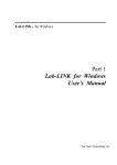
Figure 1.1 1700 Module & HT-20
A 1700 module application generally falls into one of two categories.
hýRotary
Application - The resolver position directly correlates to an angular position on
the machine. One example is monitoring a press ram. As the press cycles through one
turn, the resolver position is used to monitor and control such functions as material feed
and part blow-off.
hýLinear
Application - The resolver position correlates to a physical length. These
applications can be either single turn or multi-turn. An example of a single turn
application is a packaging machine where the resolver completes one turn for each
product. Here the resolver position is used to control when glue is applied or when the
package is cut to length. An example of a multi-turn application is monitoring the
position of a load on either a track or ball screw. In this type of application, linear
position is translated to rotary position through either a wheel or gearing. The
transducer completes several rotations in order to travel the complete distance.
AMCI also has a line of cable reel transducers for use in linear applications. A cable
reel transducer has a stranded stainless steel cable wrapped around a spring loaded
drum. As the cable is pulled out of the transducer, the drum rotates, which in turn
rotates the internal resolver. The cable is retracted by the force of the drums' spring.
Distances of up to forty-five feet can be measured with these transducers.
Physically, the Series 1700 modules are two slot cards that have one, two, three, or four
resolver inputs, called resolver, or transducer, channels. Their integral keyboard and display
allow you to setup the module and monitor position and tachometer data.
20 Gear Drive, Plymouth Ind. Park, Terryville, CT 06786
Tel: (860) 585-1254 Fax: (860) 584-1973
1-1
Chapter 1
Series 1700 Introduction
Overview (continued)
All of the modules have programmable Transducer Setup Parameters that allow you to
scale and adjust the position and tachometer data. Additional Module Setup Parameters define
the type of transducer attached to the module, the digital format of the position and tachometer
data, and how the module communicates this data to the processor. The module can be
configured to use either block or single transfers.
When configured to use block transfers, you can further configure the module to accept
programming instructions and commands over the backplane. With backplane programming
enabled, you can read back parameter values instead of position and tachometer data by
entering Read Status Mode.
Series 1700 Family Members
The twelve modules in the 1700 series are shown in the table below. The shaded out models
are multi-turn modules not covered in this manual. Refer to About this Manual, pg. I
Introduction, for more information on the manuals for these modules.
Model
Transducer
Inputs
Resolution
1731
1
10 bit (1,024 counts)
1732
2
10 bit (1,024 counts)
1733
3
10 bit (1,024 counts)
1734
4
10 bit (1,024 counts)
1741
1
13 bit (8,192 counts)
1742
2
13 bit (8,192 counts)
1743
3
13 bit (8,192 counts)
1744
4
13 bit (8,192 counts)
1761
1
12 bit (4,096) per turn, 180 turns max. (737,280 counts max.)
1761-21
1
12 bit (4,096) per turn, 180 turns max. (737,280 counts max.)
Reset input. Programmable to fractional number of turns.
1762
2
12 bit (4,096) per turn, 180 turns max. (737,280 counts max.)
1763
1
10 bit (1,024) per turn, 10,000 turns max. (10,000,000 counts max.)
Table 1.1 Series 1700 Family Members
The 1730 and 1740 modules covered by this manual are primarily intended for single turn
applications. They can be used in multi-turn applications by placing a gear ratio between the
output shaft of the machine and the transducer. AMCI has a line of transducers with an internal (x):1 ratio for use in these applications. However, you must remember that the maximum
number of counts remains fixed at either 1,024 or 8,192 counts. If you need higher resolution,
you must use a 1760 module. These modules provide up to 4,096 counts per turn over a
maximum of 180 turns. (737,280 counts max.)
See pg. 1-4, AMCI Compatible Transducers, for more information on the single and multiturn transducers available from AMCI for use with the 1730 and 1740 modules.
1-2
ADVANCED MICRO CONTROLS INC
Chapter 1
Series 1700 Introduction
Brushless Resolver Description
The brushless resolver is unsurpassed by any other type of rotary position transducer in its
ability to withstand the harsh industrial environment. An analog sensor that is absolute over a
single turn, the resolver was originally developed for military applications and has benefited
from more than 50 years of continuous use and development.
The resolver is essentially a rotary transformer with one important distinction. The energy
coupled through a rotary transformer is not affected by shaft position whereas the magnitude of
energy coupled through a resolver varies sinusoidally as the shaft rotates. A resolver has one
primary winding, the Reference Winding, and two secondary windings, the SIN and COS
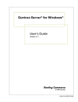
Windings. (See figure 1.2, Resolver Cut away View). The Reference Winding is located in
the rotor of the resolver, the SIN and COS Windings in the stator. The SIN and COS Windings
are mechanically displaced 90 degrees from each other. In a brushless resolver, energy is
supplied from the Reference Winding to the rotor by a rotary transformer. This eliminates
brushes and slip rings in the resolver and the reliability problems associated with them.
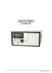
In general, the Reference Winding is excited by an AC voltage called the Reference Voltage
(VR). (See figure 1.3, Resolver Schematic). The induced voltages in the SIN and COS
Windings are equal to the value of the Reference Voltage multiplied by the SIN or COS of the
angle of the input shaft from a fixed zero point. Thus, the resolver provides two voltages
whose ratio represents the absolute position of the input shaft. (SIN θ / COS θ = TAN θ, where
θ = shaft angle.) Because the ratio of the SIN and COS voltages is considered, any changes in
the resolvers’ characteristics, such as those caused by aging or a change in temperature, are
ignored.
Rotary
Transformer
S1 (Red)
Reference Winding
COS
Winding
VC = VR COSθ
S3 (Blk)
R1 (Red/Wht)*
SIN
Winding
VR
R2 (Blk/Wht)
Rotary
Transformer
*(Wire Color)
S2 (Yel)
θ
VS = VR SINθ
S4 (Blu)
SIN and COS Windings
Figure 1.2 Resolver Cut away View
20 Gear Drive, Plymouth Ind. Park, Terryville, CT 06786
Tel: (860) 585-1254 Fax: (860) 584-1973
Figure 1.3 Resolver Schematic
1-3
Chapter 1
Series 1700 Introduction
AMCI Compatible Transducers
Table 1.2 lists the AMCI transducers compatible with the 1700 modules.
Model
Shaft
Mount
R11X-J10/7
R11X-J12/7
HT-6
HT-20
HT-20S
0.120”
0.188”
0.188”
0.625"
0.625"
Servo
Servo
Front/Side
Front/Side
Front/Side
1
1
1
1
1
HT-20C
0.625"
Front/Side
1
HT-20K
HT-20L
H25-FE
H25-FS
H25-FL
H25-SE
H25-SS
H25-SL
HT-400,
HT-400A,
HT-400B
HT-20-(X)
HTT-20-1
0.625"
0.625"
0.375”
0.375”
0.375”
0.375”
0.375”
0.375”
Front/Side
Front/Side
Flange
Flange
Flange
Servo
Servo
Servo
1
1
1
1
1
1
1
1
0.625"
Front/Side
1
0.625"
0.625"
Front
Front
(X)†
1
HTT-400-1
0.625"
Front
1
Foot
12"
Foot
76"
Foot
254"
HTCR-9n-1
HTCR-9n-6
HTCR-9n-20
0.047"
Cable
0.047"
Cable
0.047"
Cable
Turns Comments
NEMA 1, size 11 resolver
NEMA 1, size 11 resolver
NEMA 13 R11X-J12/7 transducer
NEMA 13 heavy duty transducer
HT-20 w/ side mounted connector.
NEMA 4X, stainless steel HT-20, w/ Viton® shaft seal,
conduit connector.
NEMA 4X, stainless steel HT-20, w/ Viton shaft seal.
NEMA 4X, stainless steel HT-20, w/ Nitrile shaft seal.
NEMA 4, size 25, end connector
NEMA 4, size 25, side connector
NEMA 4, size 25, integral 15 foot (3 meter) cable
NEMA 4, size 25, end connector
NEMA 4, size 25, side connector
NEMA 4, size 25, integral 15 foot (3 meter) cable
NEMA 4, HT-20 Bolt-in replacement for Autotech
RL100 transducers. Conduit, Autotech connector, or
AMCI connector styles available.
HT-20 w/ internal (X):1 gear ratio
Redundant single turn resolvers‡
Redundant single turn resolvers‡, Bolt-in replacement
for Autotech RL220 transducers.
Cable Reel Transducer, 12" span, 0.003" max.
resolution, 45 ft stranded stainless cable standard.
Cable Reel Transducer, 76" span, 0.010" max.
resolution, 45 ft stranded stainless cable standard.
Cable Reel Transducer, 254" span, 0.032" max.
resolution, 45 ft stranded stainless cable standard.
† Available gear ratios are: 2:1, 2.5:1, 2.77:1, 3:1, 4:1, 4.8:1, 5:1, 6:1, 7:1, 8:1, 9:1, 10:1, 12:1, 13:1, 15:1,
16:1, 20:1, 24:1, 36:1, 40:1, 50:1, 60:1, 64:1, 100:1, 105:1, 150:1,180:1, 250:1 and 256:1
‡ This package contains two resolvers geared 1:1 with the input shaft. Most commonly used in systems that
mandate redundant sensors, AMCI can install two different size 11 resolvers in the package per customer
requirements. Contact AMCI for more information.
Table 1.2 Compatible AMCI Transducers
1-4
ADVANCED MICRO CONTROLS INC
Chapter 1
Series 1700 Introduction
Other Compatible Transducers
In addition to AMCI transducers, the 1700 modules directly support Autotech transducers.
The Autotech models supported are:
hýAll SAC-RL100 Transducers. (Size 40, NEMA 13)
hýAll E6R and E7R-RL101 Transducers. (Size 25, NEMA 13)
hýSAC-RL101-010 Transducer. (Size 11, NEMA 1)
If your project is a new installation, or you can budget the cost of replacing the transducer,
we strongly suggest using AMCI transducers. AMCI is the only company in the marketplace
that designs and manufactures the resolvers used in its products. Our transducers and modules
are designed to work together, and when specified and installed properly will work for years to
come.
If your project involves converting system originally designed for Autotech products you
can most likely use AMCI transducers without re-designing transducer mounting brackets.
Table 1.3 lists Autotech transducer part numbers and the AMCI bolt-in replacements. Note
that the resolvers used in AMCI transducers are for AMCI products and all connectors are
AMCI standard connectors, unless otherwise stated.
Autotech
Transducer
AMCI
Transducer Comments
SAC-RL101-010
E6R-RL101-000EF
E7R-RL101-000EF
E6R-RL101-000ES
E7R-RL101-000ES
E6R-RL101-000SF
E7R-RL101-000SF
R11X-J10/7
H25-FE
Mechanically identical except that wires come out
the back instead of the side.
Bolt-in replacement. Shorter body length.
Bolt-in replacement when servo mounting.
Different bolt pattern on front, shorter body.
Bolt-in replacement. Shorter body length, side
H25-FS
connector in different location.
Bolt-in replacement when servo mounting.
E6R-RL101-000SS
H25-SS
Different bolt pattern on front, shorter body
E7R-RL101-000SS
length, side connector in different location.
SAC-RL100-010
HT-400-1 Direct replacement.
HT-400A-1 Direct replacement, Autotech connector.
SAC-RL100-M11
HT-400B-1 Direct replacement, AMCI connector.
SAC-RL220-G010C HTT-400-1 Direct replacement.
HTT-400A-1 Direct replacement, Autotech connector.
SAC-RL220-G010M
HTT-400B-1 Direct replacement, AMCI connector.
H25-SE
Table 1.3 Autotech / AMCI Transducer Cross-reference
If you decide to use your Autotech transducers, you must change the Resolver Type
parameter from the keyboard or processor. The module then sets the reference voltage to
Autotech levels. If you set the Resolver Type to Autotech and you are using a multi-channel
module, then all of the transducers must be Autotech’s. If you wish to bring both types of
transducers into a single module, you must set the Resolver Type parameter to AMCI and use
an AMCI RM-3 Reference Module to connect the Autotech transducers. For more information
on using AMCI and Autotech transducer, refer to chapter 3, pg. 3-13, Using AMCI and
Autotech Transducers Together.
20 Gear Drive, Plymouth Ind. Park, Terryville, CT 06786
Tel: (860) 585-1254 Fax: (860) 584-1973
1-5
Chapter 1
Series 1700 Introduction
The remainder of this chapter introduces the many programmable features of the
1700 modules. It also introduces backplane programming concepts that allows
you to control the module from the processor instead of using the modules
keyboard and display.
Programmable Parameters
A 1700 module is configured by setting its programmable parameters. Parameters are
broken into two groups.
hýTransducer
Setup Parameters - Six parameters that affect the position and
tachometer data of each transducer. Multi-channel modules repeat these parameters
for each transducer. For example, if you have a four channel module, you will have
four Scale Factor parameters, one for each transducer. These parameters are
programmable from the keyboard or the processor.
hýModule
Setup Parameters - Five parameters that sets module communication with
the processor and the type of resolvers attached to the card. There is only one of each
of these parameters. They are not repeated for each transducer of multi-channel
modules. They are programmable only from the keyboard.
Programmable parameters are stored in the modules nonvolatile memory. Therefore, you do
not have to configure the module after every power up. Prior to hardware revision H of the
module, the nonvolatile memory was EEPROM. This technology has the advantage of
retaining programmed values for over 100 years. Its disadvantage is its limited number of write
cycles, approximately ten thousand, before the memory will begin to fail.
With revision H, the nonvolatile memory has been changed to battery backed, non-volatile,
static RAM (nvRAM). The battery in nvRAM is rated for ten years but the nvRAM has an
unlimited number of write cycles. The nvRAM has the additional advantage of significantly
decreasing the time needed to store new parameter values.
-05 option
Prior to hardware revision H, customers could order modules with nvRAM instead of
EEPROM by adding “-05” to the end of the part number. This practice has been eliminated
because nvRAM is now standard on the modules. If your module is a replacement for an older
“-05” module, it will work correctly.
1-6
ADVANCED MICRO CONTROLS INC
Chapter 1
Series 1700 Introduction
Transducer Setup Parameters
Tachometer Response
This parameter sets the time between tachometer updates and the tachometers resolution.
Update times are 32, 60, 120, or 240 mSec. The two resolutions, available only with the
240 mSec update time, are 1.0 or 0.1 RPM.
hýThe
tachometer response default value is 240 mSec with 1.0 RPM resolution.
Update time affects the maximum speed that the module can report without error. If the
speeds listed in the table below are exceeded, the module will display erroneous data as well as
send it to the processor.
Update Time
Resolution
Max. Speed
32 mSec
1.0 RPM
5000 RPM
60 mSec
1.0 RPM
5000 RPM
120 mSec
1.0 RPM
5000 RPM
240 mSec
1.0 RPM
5000 RPM
240 mSec
0.1 RPM
999.9 RPM
Table 1.4 Maximum Tachometer Values
Scale Factor
The Scale Factor sets the number of counts per turn of the resolver.
hýThe
Scale Factor default value is 360. This gives 1 degree resolution.
modules can program the Scale Factor to any value between 2 and 1024.
hý1740 modules can program the Scale Factor to any value between 2 and 8192.
hý1730
Count Direction
This new parameter sets the direction of transducer shaft rotation to increase the position
count. If the transducer cable is wired as specified in this manual and the count direction is set
to positive, the position count will increase with clockwise rotation (looking at the shaft). If the
count direction is set to negative, the position count to increase with counter-clockwise
rotation.
hýThe
Count Direction default value is positive.
It is also possible to reverse the count direction by reversing two wires in the
transducer cable. If you are installing this module either as a replacement for
an older module or on a machine that is a copy installation of a previous
system, you will probably not need to set this parameter. Once the machine is
setup, you can easily change this parameter if the position is increasing in the
wrong direction.
20 Gear Drive, Plymouth Ind. Park, Terryville, CT 06786
Tel: (860) 585-1254 Fax: (860) 584-1973
1-7
Chapter 1
Series 1700 Introduction
Transducer Setup Parameters (continued)
Circular Offset
The Circular Offset lets you change the position count without rotating the transducer shaft.
This offset is most commonly used to force the position to the correct count after the machine
has been mechanically aligned.
hýThe
Circular Offset default value is zero.
Circular Offset can be programmed from zero to (Scale Factor -1).
hýProgramming the Scale Factor resets the Circular Offset to zero.
hýThe
The Preset Value parameter is directly related to the Circular Offset. Presetting
the position count to the Preset Value is accomplished by recalculating the
Circular Offset. For more information on the Preset Value parameter, see its
section below.
Linear Offset
The Linear Offset changes the range of position counts by adding a fixed number to it. The
Linear Offsets use is best illustrated with an example.
A 1741 is used to measure a 5.000 meter span with one millimeter resolution. Therefore, the total number of counts over the
full travel is:
7.5 m
5 min
1.162
Span
2.5 m
Linear
.581 in
Offset
0m
Figure 1.4
Linear Offset
Example
5.000 meters * 1000 mm/meter = 5000 counts.
The Scale Factor parameter is then set to this value. The 5.000
meters that the transducer measures is in the range of 2.500 to
7.500 meters on the machine. You can use the Linear Offset to
force the module to send the position data to the processor in the
correct format instead of using the processor to add an offset once
the position value is in the data table. The formula for the Linear
Offset is:
Minimum Desired Value *
Resolution
= Linear Offset
2.500 meters
* 1000 mm/meter = 2500 counts
hýThe
Linear Offset default value is zero.
hýThe Linear Offset can be programmed from zero to (9,999 - (Scale Factor -1)).
hýProgramming the Scale Factor resets the Linear Offset to zero.
Preset Value
The Preset Value parameter allows you to set the value of position count without calculating
the required offset. Programming the Preset Value does not change the position data, it only
sets the value that the position will change to when a Preset Command is initiated. The
position can be preset from the keyboard or with a backplane command.
hýThe
Preset Value defaults to zero.
hýThe Preset Value can be programmed from zero to (Scale Factor - 1).
hýProgramming the Scale Factor resets the Preset Value to zero.
hýIf the Linear Offset value is not equal to zero, the new position value will be (Linear
Offset + Preset Value) after it is preset.
1-8
ADVANCED MICRO CONTROLS INC
Chapter 1
Series 1700 Introduction
Module Setup Parameters
Data Format
This parameter allows you to choose the format of the position and tachometer data reported
over the backplane. The choices are Binary or BCD. It is included for PLC-2 users that require
BCD data for PLC-2 math instructions. All other applications should chose Binary data format.
hýThe
hýThe
Data Format parameter default value is Binary.
Data Format parameter can only be changed from the keyboard.
1) AMCI uses the most significant bit of the position and tachometer data
words as error bits. Therefore, the maximum position value that can be
transmitted in BCD is 7,999. If the sum: (Linear Offset + Scale Factor) is
greater than 8,000, the module will lock the Data Format parameter to its
Binary value. You will not be able to change the Data Format parameter
until you decrease the value of either the Linear Offset or Scale Factor.
2) The 1731 and 1741 transfer their data using either block or single transfers.
If you select single transfers, the Data Format parameter is locked to Binary.
Transfer Type
If you have a 1731 or 1741 module, this parameter allows you to define how the module
will communicate over the backplane. You select either block or single transfer. All multichannel modules have this parameter locked to the block transfer value.
hýThe
hýThe
Transfer Type default value is block transfer.
Transfer Type can only be changed from the keyboard.
1) If you configure the module for single transfers, you will not be able to
program the Transducer Setup Parameters from the backplane.
2) If you configure the module for single transfers, the Data Format parameter
will be locked to its Binary value
3) After changing this parameter, you must cycle power to the module to
reinitialize the A-B backplane interface chip.
PLC Program
The PLC Program parameter tells the module to accept or ignore programming instructions
from the backplane. This parameter is only available if you have selected block transfers with
the Transfer Type parameter. If you selected single transfers, the Single Transfer Length
parameter is shown instead.
hýThe
PLC Program default value, read only, prevents the module from accepting
programming instructions. In order to enable backplane programming, you must set
the parameter to program enabled.
hýThe PLC Program parameter is only programmable from the keyboard.
1) When backplane programmable, the module requires an additional word in
its block transfer read file. Because of this, you may have to modify your
existing data file sizes as well as your ladder logic if upgrading your system.
2) After changing this parameter, you must cycle power to the module to reinitialize the A-B backplane interface chip.
20 Gear Drive, Plymouth Ind. Park, Terryville, CT 06786
Tel: (860) 585-1254 Fax: (860) 584-1973
1-9
Chapter 1
Series 1700 Introduction
Module Setup Parameters (continued)
Single Transfer Length
The Single Transfer Length parameter is a new parameter used to specify either a 16 or 32
bit transfer. This parameter is only available if you have selected single transfers with the
Transfer Type parameter. If you selected block transfers, the PLC Program parameter is shown
instead.
hýThe
Single Transfer Length default is 16 bit. This allows the transfer of position data
only. Setting the parameter to 32 bit allows the transfer of both the position and
tachometer data.
hýThe Single Transfer Length parameter is only programmable from the keyboard.
1) If the Single Transfer Length parameter is set to 16 bit, the chassis can be
configured for 2-slot, 1-slot, or ½-slot addressing. If the parameter is set to
32 bit, you must use 1-slot or ½-slot addressing.
2) After changing this parameter, you must cycle power to the module to reinitialize the A-B backplane interface chip.
-08 option
Prior to hardware revision H, customers could order modules with 32 bit single transfer by
adding “-08” to the end of the part number. This practice has been eliminated because 32 bit
single transfer is now standard on the modules. If your module is a replacement for an older
“-08” module, it will work correctly if the Transfer Type parameter is set to single and the
Single Transfer Length parameter is set to 32 bit.
Resolver Type
The Resolver Type parameter is a new parameter that makes most Autotech transducers
compatible with the Series 1700 modules.
hýThe
Resolver Type default value is AMCI, resolver 1. If you are using Autotech
transducers, set this parameter to resolver 2.
hýThe Resolver Type parameter is only programmable from the keyboard.
If you plan to use both AMCI and Autotech resolvers with a single module you
must set the Resolver Type to AMCI, resolver 1. You will need an RM-3
Reference Module to interface the Autotech transducers with the card. See
Chapter 3, pg. 3-13, Using AMCI and Autotech Transducers Together for more
information on using an RM-3.
1-10
ADVANCED MICRO CONTROLS INC
Chapter 1
Series 1700 Introduction
Backplane Programming
When a Series 1700 module is configured to use block transfers, you have the option of
programming the module using data sent to it by block transfer writes. (See Transfer Type
Parameter and PLC Program Parameter sections, pgs. 1-8, 1-9.) The programming format is a
series of Program Instructions as shown below. Block transfers can transmit a maximum of
sixty-four words. However, this does not limit how many parameters you can program at one
time.
COMMAND WORD
First Data Word
PROGRAM
INSTRUCTION
program instruction is made up
of a Command Word and zero or
more Data Words.
hýAll
Last Data Word
PROGRAM
INSTRUCTION
hýEach
COMMAND WORD
COMMAND WORD
First Data Word
PROGRAM
INSTRUCTION
Last Data Word
Last Command or Data Word
transducer setup parameters can
be programmed from the backplane.
Module setup parameters cannot be
programmed from the backplane.
hýThere
are nine additional program
instructions called Auxiliary
Commands. These commands do
not have data associated with them
and allow you to preset the position,
enable or disable programming from
the keyboard, clear programming
errors and transducer faults, and
enter or exit Read Status Mode.
Four additional commands are
enabled when the module is in read
status mode. Use these commands
to tell the module which parameter
values to transmit to the PLC instead
of position and tachometer data.
Figure 1.5 1700 Programming Structure
Auxiliary Commands
Auxiliary Commands affect the operation of the module and do not have data associated
with them. There are nine commands.
hýClear
Errors - This command clears any programming error messages and any
transducer faults.
hýPreset Transducer (1-4) - These four commands set the position count of
transducer (1-4) equal to the programmed preset value.
hýDisable Keyboard - Disables all programming from the keyboard. Parameter
values can be monitored but they cannot be changed.
hýEnable Keyboard - This command counteracts a previous Disable Keyboard
command. The status of the keyboard disable is retained when power is removed.
The only way to enable the keyboard after a Disable Keyboard command has been
accepted is with this command.
20 Gear Drive, Plymouth Ind. Park, Terryville, CT 06786
Tel: (860) 585-1254 Fax: (860) 584-1973
1-11
Chapter 1
Series 1700 Introduction
Auxiliary Commands (continued)
hýEnter
Read Status Mode - This command puts the module in read status mode.
While in this mode, the module will transmit parameter values instead of position
and tachometer data. Four additional commands are enabled while in this mode that
allow you to specify which parameter values are to be read back.
hýExit
Read Status Mode - This command places the module back into its normal
mode of operation. Position and tachometer data will be transmitted after this
command is accepted.
Read Status Mode
This special mode of operation allows you to read back the transducer setup
parameter values. Position and tachometer data is not transmitted while in this
mode.
Because the block transfer read length from a 1700 module is fixed, it is not to read back all
of the parameter values with a single block transfer. For this reason, four additional commands
are enabled while in this mode. These commands allow you to specify which parameters are to
be read back. Once specified, the parameter values will be transmitted with every block
transfer read until new parameters are specified or you exit read status mode.
For more information on read status mode, refer to Chapter 6, Backplane Programming.
1-12
ADVANCED MICRO CONTROLS INC
Chapter 2
Module Description
This chapter describes the physical layout of a Series 1700 module as well as
keyboard programming.
Front Panel Description
Program Switch - (On other side of PC
Board, hidden from view.) Used to
enable programming the module from the
keyboard. A two pin header next to the
switch can be removed to disable Program
Mode. The switch can also be disabled
from the processor.
Function Display - Used to display position
data and parameter values. The eight LED
indicators designate what is showing on the
display. When programming a parameter,
a blinking digit in the display shows the
position of the Cursor.
Status Indicators - Indicates the operating
status of the module.
PRG - Yellow light is on when the module is in
Program Mode.
RUN - Green light is blinking when the module
is operating.
FAULT - Red light is on when there is a module
fault. The type of fault is shown on
the display.
Keyboard - Used to examine position and
tachometer data as well as examine or
change the programming of the module.
Transducer Input Connector - Connector for
one to four transducers. A fourteen pin
connector is shown. The 1731, 1732,
1741, and 1742 modules have an eight pin
connector.
Figure 2.1 Series 1700 Front Panel
20 Gear Drive, Plymouth Ind. Park, Terryville, CT 06786
Tel: (860) 585-1254 Fax: (860) 584-1973
2-1
Chapter 2
Module Description
Program Mode vs. Display Mode
The front panel has two operating modes.
hýProgram
hýDisplay
Mode – (Yellow PRG light on) The parameters can be modified from
the keyboard. The position can be preset by pressing the
>CLEAR@ key while displaying the position value.
Mode – (Yellow PRG light off) The parameters can be inspected, but not
modified. You cannot preset the position from the keyboard.
Program Mode and Display Mode refer to the modules’ front panel only. Once enabled by
setting the Transfer Type and PLC Program parameters appropriately, you can always program
the module from the backplane.
The module can be locked into Display Mode in one of two ways. The first is by removing
a jumper on the module. The second is writing the Disable Keyboard auxiliary command from
the processor. It is usually good practice to lock the module in display mode once the system is
operational. This will prevent someone from accidentally changing the parameters while the
system is running. The only times that changes to the programming should be allowed are
during set-up or trouble shooting procedures.
Program Switch
The Program Switch is used to quickly enable or
disable program mode as long as the 1700 module
has not been locked in display mode from the
processor. The module is in program mode when
the switch is pushed towards the back of the
module. The module is in display mode when the
switch is pushed towards the front of the module.
The yellow PRG light is on when the module is in
program mode.
The Program Switch can be disabled by removing the jumper on the two pin header next to the
switch. Removing this jumper locks the 1700 in
display mode. You can also lock the module in
display mode with the Disable Keyboard auxiliary
command. See chapter 1, pg. 1-10, Auxiliary
Commands for more information on enabling or
disabling the keyboard from the processor.
Remove system power before
removing or installing any
module in an I/O chassis. Failure to observe this
warning can result in damage to the module's
circuitry and/or undesired operation with possible
injury to personnel.
Two Pin Header
with Jumper Installed.
PROGRAM
DISPLAY
Program Switch in
Program Mode position.
Figure 2.2 Program
Switch
2-2
ADVANCED MICRO CONTROLS INC
Chapter 2
Module Description
Using the Function Display and Keyboard
You can examine position and tachometer values as well as inspect or program all of the
programmable parameters using the display and keyboard. The >FUNCTION@ key, along with the
>Ç@ and >Æ@ keys, are used to cycle between the displays. Figure 2.3 shows the display order.
POWER UP
You will see either the PLC Program or the
Single Transfer Length display. The value of
the Transfer Type parameter dictates which
display is shown.
Navigating in Program Mode
The >FUNCTION@ key is still used to cycle
through the displays.
Tachometer Data
Transducer Setup Parameters
The >FUNCTION@ and >Ç@ keys cycle you
through the displays in one direction (Down in
the figure). The >Æ@ýcycles you through the
displays in the opposite direction. Note that
the display order is circular. Pressing the
>FUNCTION@ key while displaying the resolver
type parameter will return you to the position
display. Pressing the >Æ@ýkey will then return
you the resolver type parameter.
Position Data
Module Setup Parameters
When compared to program mode, display
mode is easier to navigate. If you are unfamiliar with the module, learn how to navigate
between displays while in display mode.
Navigating in program mode will then be
easier to learn.
These displays are repeated for each transducer.
Press the [NEXT] key to cycle through the channels.
Navigating in Display Mode
Tach Response
Scale Factor
Count Direction
Circular Offset
Linear Offset
Preset Value
Data Format
Transfer Type
Block
PLC Program
Single
Single Transfer
Length
When you switch to a parameter display,
the first digit of the value will be blinking.
Resolver Type
This shows the position of the Cursor. Use the
>Ç@ and >Æ@ keys to move the cursor and the
>▲@ and >▼@ keys to change the value of the
Figure 2.3 Module Display Order
digit under the cursor. To quickly set most
parameters to zero, press the >CLEAR@ key.
Once the parameter value is correct, press the >ENTER@ key to accept it. The cursor is removed
from the display if the new value is valid.
The module will only accept valid values for the parameters. If the module does not accept
a value, it will return the display to the last valid number and move the cursor to the first digit.
The valid range for many parameters is based on the values of other parameters. If the module
does not accept a new value, check the other parameter settings.
Pressing the >FUNCTION@ key at any time will remove the cursor and the module will display
the last valid setting for the parameter. You can then use >FUNCTION@ñý>Ç@ñ or >Æ@ keys to
move to the next or previous display.
20 Gear Drive, Plymouth Ind. Park, Terryville, CT 06786
Tel: (860) 585-1254 Fax: (860) 584-1973
2-3
Chapter 2
Module Description
Using the Function Display and Keyboard (continued)
Switching Between Channels
Pressing the >NEXT@ key will cycle through the transducer channels when displaying the
position value, tachometer value, or transducer setup parameters. You will remain in the same
display, only switching channels. For example, if you have a 1744 and are displaying the Scale
Factor parameter, pressing the >NEXT@ key four times will cycle you through the four Scale
Factor values.
The first digit of these displays usually tells you which channel is being displayed. The one
exception is the Count Direction display. This display shows “dir” followed by the channel
number.
Indicator LED Patterns
The eight LEDs above the seven segment displays are the indicator LEDs. Figure 2.4 is a
list of the displays and their indicator LED patterns. Note that some of the parameters have the
same indicator pattern. In these cases, the actual displays are different enough to distinguish
between the parameters.
POS TAC SF
O
A
B
C
D
POSITION
TACHOMETER
TACH RESPONSE
SCALE FACTOR
TRANSDUCER
SETUP
PARAMETERS
COUNT DIRECTION
CIRCULAR OFFSET
LINEAR OFFSET
PRESET VALUE
DATA FORMAT
TRANSFER TYPE
MODULE
SETUP
PARAMETERS
PLC PROGRAM
SINGLE TRANSFER LENGTH
RESOLVER TYPE
LED OFF
LED ON
Figure 2.4 Indicator LED Patterns
2-4
ADVANCED MICRO CONTROLS INC
Chapter 2
Module Description
Position Display
As shown in figure 2.5a, the position display shows the current position when a transducer
is properly attached to the channel. The first digit is the transducer channel. If you have a
multi-channel module, press the >NEXT@ key to cycle through the additional position displays.
If there is a transducer fault on the input channel, the position display will change to the one
shown in figure 2.5b. The red FAULT LED is lit when there is a transducer fault. If this LED
is on while the position is displayed, the fault is on one of the other channels. Use the >NEXT@
key to switch to the faulted channel. The fault can be cleared by pressing the >CLEAR@ key if
the 'Err1' message is blinking.
Refer to the Error Messages section on page 2-9 for more information on the causes of a
transducer fault.
PLC SERIES
Fig A
CURRENT POSITION
PLC SERIES
Fig B
TRANSDUCER FAULT
(ERROR 1)
CHANNEL 1
Figure 2.5 Position and Transducer Fault Displays
Tachometer Display
PLC SERIES
Figure 2.6 Tachometer
Display
The tachometer display shows the current speed of the
transducer in revolutions per minute with either 1.0 or 0.1 RPM
resolution.
If there is a transducer fault, the display will show the ‘Err1’
message instead of the current speed. (See Position Display
above.) The red FAULT LED is lit when there is a transducer
fault. If this LED is on while the tachometer is displayed, the
fault is on one of the other channels. Use the >NEXT@ key to
switch to the faulted channel. The fault can be cleared by
pressing the >CLEAR@ key if the 'Err1' message is blinking.
20 Gear Drive, Plymouth Ind. Park, Terryville, CT 06786
Tel: (860) 585-1254 Fax: (860) 584-1973
2-5
Chapter 2
Module Description
Transducer Setup Parameters
The following are the front panel displays of the transducer setup parameters along with
default values, range of values, and any special programming instructions. The first digit of
these displays usually tells you which channel is being displayed. The one exception is the
count direction display. This display shows “dir” followed by the channel number. If you have
a multi-channel module, use the >NEXT@ key to switch between channels.
The page number given in the heading is the page in chapter one that more fully describes
the function of the parameter.
Tachometer Response Pg. 1-6
Default: 240 mSec update, 1.0 RPM resolution
PLC SERIES
Figure 2.7 Tach
Response
Range: 32 mSec update, 1.0 RPM resolution
60 mSec update, 1.0 RPM resolution
120 mSec update, 1.0 RPM resolution
240 mSec update, 1.0 RPM resolution
240 mSec update, 0.1 RPM resolution
Special: The >▲@ and >▼@ keys change the entire value, not one digit.
The >Æ@ and >Ç@ keys have no effect. The display shows
‘0240’ for 1 RPM resolution, ‘240.0’ for 0.1 RPM resolution.
Scale Factor Pg. 1-6
Default: 360 Counts (1° resolution)
PLC SERIES
Figure 2.8 Scale
Factor
Range: 2 to 1024 counts inclusive (1731, 1732, 1733, 1734)
2 to 8192 counts inclusive (1741, 1742, 1743, 1744)
Programming this parameter will reset the Circular
Offset, Linear Offset, and Preset Value parameters
to their default settings of zero.
Count Direction Pg. 1-6
Default: Positive. (Clockwise increasing counts)
PLC SERIES
Figure 2.9 Count
Direction
2-6
Range: Positive (Clockwise increasing)
Negative (Counter-clockwise increasing)
Special: The >▲@ and >▼@ keys change the entire value, not one
digit. The >Æ@ and >Ç@ keys have no effect. The transducer
channel number is the fourth digit, after ‘dir’.
ADVANCED MICRO CONTROLS INC
Chapter 2
Module Description
Transducer Setup Parameters (continued)
Circular Offset Pg. 1-7
Default: 0
PLC SERIES
Range: 0 to (Scale Factor - 1)
Programming the Scale Factor parameter resets the
Circular Offset to zero.
Figure 2.10 Circular
Offset
Linear Offset Pg. 1-7
Default: 0
PLC SERIES
Range: 0 to (9,999 - (Scale Factor - 1))
Programming the Scale Factor parameter resets the
Linear Offset to zero.
Figure 2.11 Linear
Offset
Preset Value Pg. 1-7
Default: 0
PLC SERIES
Range: 0 to (Scale Factor -1)
Programming the Scale Factor parameter resets the
Preset Value to zero.
If the Linear Offset is not equal to zero, the new
position value will be (Linear Offset + Preset Value).
Figure 2.12 Preset
Value
Module Setup Parameters
The following are the front panel displays of the module setup parameters along with default
values, range of values, and any special programming instructions. The page number given in the
heading is the page in chapter one that more fully describes the function of the parameter.
For all of these displays, the >▲@ and >▼@ keys change the entire value, not one digit. The >Æ@
and >Ç@ keys have no effect.
Data Format Pg. 1-8
Default: Binary data format
PLC SERIES
Range: Binary
BCD
Figure 2.13 Data
Format
20 Gear Drive, Plymouth Ind. Park, Terryville, CT 06786
Tel: (860) 585-1254 Fax: (860) 584-1973
2-7
Chapter 2
Module Description
Module Setup Parameters (continued)
Transfer Type Pg. 1-8
Default: Block transfer
PLC SERIES
Range: Block
Single
Figure 2.14 Transfer
Type
PLC Program Pg. 1-8
Default: Read Only
PLC SERIES
Range: Read Only
Program Enabled
This parameter is only shown when the Transfer
Type parameter is set to block transfer. If Transfer
Type is set to single transfer, the Single Transfer
Length display is shown.
Figure 2.15 PLC
Program
Single Transfer Length Pg. 1-9
Default: 16 bit
PLC SERIES
Figure 2.16 Single
Transfer Length
Range: 16 bit
32 bit
This parameter is only shown when the Transfer
Type parameter is set to single transfer. If Transfer
Type is set to block transfer, the PLC Program
display is shown.
Resolver Type Pg. 1-9
Default: 1: AMCI resolvers
PLC SERIES
Range: 1: AMCI resolvers
2: Autotech Resolvers
Figure 2.17 Resolver
Type
2-8
ADVANCED MICRO CONTROLS INC
Chapter 2
Module Description
Error Messages
There are three types of faults that a 1700 module will recognize.
hýTransducer
Fault (Error 1) – A problem exists on a transducer channel.
hýnvRAM Fault (Error 2) – A problem exists with the non-volatile RAM or
parameter values are not stored correctly.
hýReference
Voltage Fault – The reference voltage constants could not be automatically restored while clearing a nvRAM error.
In all cases, the red FAULT LED will be on and the module will display an error message as
shown below. These errors are also reported over the backplane. See Chapter 7 Data Format,
for information on how errors are reported over the backplane.
Transducer Fault (Error 1)
PLC SERIES
Figure 2.18
Transducer Fault
This message is only shown when the module is displaying position or
tachometer data. The parameters are displayed normally. If the FAULT
LED is on while the position is displayed, the fault is on one of the other
channels. Use the >NEXT@ key to switch to the faulted channel. The fault
can be cleared by pressing the >CLEAR@ key if the 'Err1' message is
blinking. There are six major causes of a transducer fault.
hýBroken
or intermittent transducer cable
transducer
hýImproper wiring of the transducer cable
hýImproper installation of the transducer cable
hýFaulty transducer
hýFaulty module
hýNon-compatible
nvRAM Fault (Error 2)
All of the parameters are stored in a non-volatile static RAM memory when power is removed from the module. The nvRAM has an integral lithium battery that will maintain the
parameter values in the absence of power for approximately ten years from the date of
manufacture.
It is remotely possible that the values can become corrupted through electrical noise or an
inopportune power outage. If this occurs, the module display will change to figure 2.19.
PLC SERIES
Figure 2.19 nvRAM
Error
This message is displayed at all times. This error can be cleared by
pressing the >CLEAR@ key. If the message remains after pressing the
>CLEAR@ key, the nvRAM is damaged. If the message appears on every
power up but can be cleared, the battery is discharged. In either case,
the module must be returned to AMCI for repairs. See the inside front
cover, Returns Policy, for additional information.
A 1700 module stores constants in the nvRAM that allow it to adjust the
reference voltage for either AMCI or Autotech transducers. If these
constants are corrupted, the module will recalculate them as long a
working transducer is attached. While calculating the constants, the
display will show “rEF_nn” where nn = 00 to 99. Once recalculated, the
display will change to the position display. If these constants cannot be
calculated, the display changes to the reference voltage fault display.
20 Gear Drive, Plymouth Ind. Park, Terryville, CT 06786
Tel: (860) 585-1254 Fax: (860) 584-1973
2-9
Chapter 2
Module Description
Error Messages (continued)
Reference Voltage Fault
PLC SERIES
Figure 2.20
Reference Voltage
Fault
A 1700 module stores adjustment constants in the nvRAM memory that
allow it to set the reference voltage for either AMCI or Autotech transducers. Usually, these constants can be restored automatically when a
nvRAM fault is cleared. If the restoration fails, the module displays this
“reference error” message. Make sure a working transducer is properly
attached to the module and press the >CLEAR@ key. The module will
then recalculate the constants. If the message remains after pressing the
>CLEAR@ key, contact AMCI. See the inside front cover, 24 Hour
Technical Support Number, for more information on contacting AMCI.
Transducer Input Connector
The transducer input connector of a 1731, 1732, 1741, or 1742 module has eight contacts
while the connector of a 1733, 1734, 1743, or 1744 module has fourteen contacts. The following table lists the AMCI and Phoenix Contact part numbers on the mating connectors.
8 Pin Connector
14 Pin Connector
AMCI Part #
MS-8
MS-14
Phoenix Part #
MSTB2.5/8-ST-5.08
1757077
MSTB2.5/14-ST-5.08
1757132
Table 2.1 Transducer Input Connector
Figure 2.21 shows the pinout to industry standard resolver wire designations. Cabling
information for AMCI and Autotech transducers is given in chapter 3, starting on page 3-8,
Transducer Cable Installation.
14
13
12
11
10
9
8
7
6
5
4
3
2
1
S3, CH4
S4, CH4
S3, CH3
S4, CH3
S1 & S2, CH3 & CH4
CH3 & CH4 Shields
S3, CH2
S4, CH2
S3, CH1
S4, CH1
S1 & S2, CH1 & CH2
CH1 & CH2 Shields
R2, All Channels
R1, All Channels
hýCH
–
–
hýS1/S3 –
hýS2/S4 –
hýR1/R2
Channel Number
Reference Winding
COS Winding
SIN Winding
Figure 2.21 Transducer Input
Connector
2-10
ADVANCED MICRO CONTROLS INC
Chapter 3
Installation
This chapter describes how to install the Series 1700 module into the I/O chassis.
It also give information on installing AMCI transducers. This includes information
on transducer mounting, shaft loading, and cable installation. Information on
interfacing Autotech transducers is also included.
Power Requirements
The 1700 modules draw power from the I/O chassis +5Vdc supply. The maximum current
draw is dependent on the number of transducer channels and is given in the table below. Add this
to the power requirements of all other modules in the chassis when sizing the chassis power supply.
Model Number
1731/1741 1732/1742 1733/1743 1734/1744
Maximum Current Draw
675 mA
700 mA
725 mA
750 mA
Table 3.1 Backplane Current Draw
Installing the Module
Remove system power before removing or installing any module in an
I/O chassis. Failure to observe this warning may result in damage to the
module's circuitry and/or undesired operation with possible injury to
personal.
Install the module in a single slot
pair within the chassis. A slot
pair is two adjacent backplane
slots, the left of which is even
numbered. Most A-B chassis
have the slots numbered on the
backplane silkscreen. Figure 3.1
shows two modules. The module
on the left is installed correctly in
a single slot pair while the
module on the right is incorrectly
installed in two slot pairs.
Fig 3.1 Module Installation
All addressing and programming examples in this manual assume that the
module is installed in a single slot pair.
Keying Bands
Plastic keying bands can be inserted into the top backplane connector to prevent the
insertion of other modules. Insert the bands between the following pins:
hýPins
hýPins
28 and 30
32 and 34.
20 Gear Drive, Plymouth Ind. Park, Terryville, CT 06786
Tel: (860) 585-1254 Fax: (860) 584-1973
3-1
Chapter 3 Installation
Transducer Specifications
Specification
Shaft Diameter
Radial Shaft Loading
Axial Shaft Loading
Starting Torque
Moment of Inertia
Weight
Enclosure
All HT and HTT’s
All H25’s
HT-6
0.625"
0.375"
40 lbs. Max.
0.188"
400 lbs. Max.
200 lbs. Max.
20 lbs. Max.
8 lbs. Max.
4 lbs. Max.
8 oz.in. @ 25°C
1.5 oz.in. @ 25° C
0.5 oz.in. @ 25°C
2
-4
20 oz-in-sec²
4 oz-in-sec
2.1 x 10 oz-in-sec²
4 lbs.
1 lb.
0.7 lb.
NEMA 13 or 4X
NEMA 4
NEMA 13
Environmental (All Transducers)
Operating Temp
-20 to 125°C
Shock
50G’s for 11 mSec
Vibration
5 to 2000 Hz @ 20 G’s
Table 3.2 Transducer Specifications
Transducer Mounting
All AMCI resolver based transducers are designed to operate in the industrial environment
and therefore require little attention. However, there are some general guidelines that should be
observed to ensure long life.
hýLimit
transducer shaft loading to the following maximums:
All 0.625" Shafts
All 0.375" Shafts
All Other Shafts
Radial Load
Axial Load
100 lbs. (445 N)
30 lbs. (133 N)
4 lbs. (17.8 N)
50 lbs. (222 N)
15 lbs. (66.7 N)
2 lbs. (8.9 N)
Table 3.3 Transducer Bearing Loads
hýMinimize
shaft misalignment when direct coupling shafts. Even small misalignments
produce large loading effects on front bearings. It is recommended that you use a
flexible coupler whenever possible.
Transducer Outline Drawings
The appropriate outline drawing is included with the transducer when shipped. Outline
drawings for select transducers are also available on the following pages of this manual. If you
are using one of the transducers printed here and need a dimensional drawing, check our web site
or contact us and we will fax you the spec sheet.
3-2
ADVANCED MICRO CONTROLS INC
Chapter 3
Installation
Transducer Outline Drawings (continued)
HT-20: Anodized Aluminum Body, 1070 Steel Shaft, NEMA 13
2.500" (63.50)
4.75" (120.7)
2.000" (50.80)
0.750" (19.05)
KEYWAY
3.250" (82.55)
0.500"
(12.70)
0.1885(4.79) 0.106(2.69)
DEEP X 1.0(25.4)
X
0.1895(4.81) 0.108(2.74)
1.000"
(25.40)
KEY
0.187(4.75)
SQ. X 1.0(25.4)
0.188(4.78)
1.000"
(25.40)
1.1815" (30.010)
1.1807" (29.990)
2.500" 2.000"
(63.50)
(50.80)
1.500"
(38.10)
0.6247" (15.867)
0.6237" (15.842)
0.250" (6.35)
0.150" (3.81)
0.250" (6.35)
1.25"
MS3102E16S-1P
Connector
0.700" (17.78) max.
Total clearance of 3.5" (89)
needed for removal of
mating connector
(31.8)
1/4-20 UNC-2B
0.50" (12.7) min. depth.
Eight places
( ) = Dimensions in millimeters
Figure 3.2 HT-20 Outline Drawing
HT-20S: Anodized Aluminum Body, 1070 Steel Shaft, NEMA 13
2.500" (63.50)
MS3102E16S-1P
Connector
4.75" (120.7)
2.000" (50.80)
0.750" (19.05)
KEYWAY
3.250" (82.55)
0.500"
0.1885(4.79) 0.106(2.69)
DEEP X 1.0(25.4)
X
0.1895(4.81) 0.108(2.74)
1.000"
(25.40)
(12.70)
KEY
0.187(4.75)
SQ. X 1.0(25.4)
0.188(4.78)
1.000"
(25.40)
1.1815" (30.010)
1.1807" (29.990)
2.500" 2.000"
(63.5)
(50.8)
1.500"
(38.10)
0.6247" (15.87)
0.6237" (15.84)
0.250" (6.35)
0.150" (3.81)
0.250" (6.35)
1.25"
(31.8)
0.60" (15.2) max.
Total clearance of 3.5" (89) needed
for removal of mating connector.
1/4-20 UNC-2B
0.50" (12.7) min. depth.
Eight places
( ) = Dimensions in millimeters
Figure 3.3 HT-20S Outline Drawing
HT-20K/L: Hard Coat Anodized Aluminum Body, 303 Stainless Steel Shaft, NEMA 4X
HT-20K SUPPLIED WITH VITON SHAFT SEAL
HT-20L SUPPLIED WITH NITRILE SHAFT SEAL
2.500" (63.50)
4.75" (120.7)
2.000" (50.80)
KEYWAY
1.000"
0.750" (19.05)
3.250" (82.55)
0.500"
(12.70)
0.1885(4.79) 0.106(2.69)
DEEP X 1.0(25.4)
X
0.1895(4.81) 0.108(2.74)
(25.40)
KEY
1.000"
0.187(4.75)
SQ. X 1.0(25.4)
0.188(4.78)
(25.4)
1.500"
2.500" 2.000"
(63.5)
(38.1)
(50.80)
0.6247" (15.867)
0.6237" (15.842)
0.250" (6.35)
0.250" (6.35)
1.25"
(31.8)
1/4-20 UNC-2B
0.50" (12.7) min. depth
Eight places.
MS3102E16S-1P
Connector
( ) = Dimensions in millimeters
0.700" (17.78) max.
Total clearance of 3.5" (89)
needed for removal of
mating connector
Figure 3.4 HT-20K/L Outline Drawing
20 Gear Drive, Plymouth Ind. Park, Terryville, CT 06786
Tel: (860) 585-1254 Fax: (860) 584-1973
3-3
Chapter 3 Installation
Transducer Outline Drawings (continued)
H25FE: Anodized Aluminum Body, 303 Stainless Steel Shaft, NEMA 4
( ) = Dimensions in millimeters
1.032"
0.218" (5.54) dia.
Four places.
(26.21)
typ.
0.250"
0.300" (7.62)
0.700" (17.78) max.
Total clearance of 3.5" (89)
needed for removal of
mating connector.
(6.35)
0.3747" (9.517)
0.3744" (9.510)
1.032"
(26.21)
typ.
2.65"
(67.3)
0.900" (22.86)
0.850" (21.59)
1.250" (31.75)
1.249" (31.72)
2.35" (58.8) max.
2.50" (63.5) dia.
MS3102E16S-1P
Connector
2.65" max.
(67.3)
Figure 3.5 H25FE Outline Drawing
H25SE: Anodized Aluminum Body, 303 Stainless Steel Shaft, NEMA 4
( ) = Dimensions in millimeters
2.50" (63.5)
0.300" (7.62)
0.700" (17.78) max.
Total clearance of 3.5"(89)
needed for removal of
mating connector.
0.3747" (9.517)
0.3744" (9.510)
2.31"
(58.64)
1.250" (31.75)
1.249" (31.72)
0.900" (22.86)
0.850" (21.59)
#8-32 UNF- 2B. 0.18" (4.6) min depth. Six
places, 60° apart on a 1.875" (47.63) B.C.
0.10" (2.5)
0.10" (2.5)
2.42" (61.5) max.
MS3102E16S-1P
Connector
Figure 3.6 H25SE Outline Drawing
3-4
ADVANCED MICRO CONTROLS INC
Chapter 3
Installation
Transducer Outline Drawings (continued)
H25FS: Anodized Aluminum Body, 303 Stainless Steel Shaft, NEMA 4
( ) = Dimensions in millimeters
1.43" sq.
(36.3)
1.13" (28.7) max.
Total clearance of 3.5"(89)
needed for removal of
mating connector.
2.65" (67.3)
max.
MS3102E16S-1P
Connector
0.300" (7.62)
0.3747" (9.517)
0.3744" (9.510)
2.65"
(67.3)
2.50"
1.250" (31.75)
1.249" (31.72)
(63.5)
1.032"
(26.21)
typ.
1.032"
(26.21)
2.65" (67.3)
typ.
0.218" (5.54) dia.
Four places
0.900" (22.86)
0.850" (21.59)
.250" (6.35)
2.65" (67.3) max.
Figure 3.7 H25FS Outline Drawing
H25SS: Anodized Aluminum Body, 303 Stainless Steel Shaft, NEMA 4
( ) = Dimensions in millimeters
1.20" (30.5) max.
Total clearance of 3.5"(89) needed
for removal of mating connector.
1.43" sq.
(36.3)
0.300" (7.62)
2.65" (67.3)
max.
MS3102E16S-1P
Connector
0.300" (7.62)
0.3747" (9.517)
0.3744" (9.510)
2.50"
2.31"
(63.5)
(58.6)
1.250" (31.75)
1.249" (31.72)
#8-32 UNF-2B.
0.18" (4.6) min. depth.
Six places, 60° apart
on 1.875" (47.62) B.C.
0.900" (22.86)
0.850" (21.59)
0.10" (2.5)
0.10" (2.5)
2.70" (68.6) max.
Figure 3.8 H25SS Outline Drawing
20 Gear Drive, Plymouth Ind. Park, Terryville, CT 06786
Tel: (860) 585-1254 Fax: (860) 584-1973
3-5
Chapter 3 Installation
Transducer Outline Drawings (continued)
H25FL: Anodized Aluminum Body, 303 Stainless Steel Shaft, NEMA 4
1.032"
0.218" (5.54) dia.
Four places
(26.21)
typ.
0.250" (6.35)
0.300" (7.62)
LIQUID TIGHT STRAIN RELIEF
Hummel P/N 1.293.1201.71
Accepts Cables 0.20" (5.1) to 0.35" (8.9) Dia.
0.3747" (9.517)
0.3744" (9.510)
1.032"
(26.21)
typ.
2.65"
(67.31)
0.50" NPT
3.4" (86)
0.900" (22.86)
0.850" (21.59)
1.250" (31.75)
1.249" (31.72)
2.65" (67.31)
2.95" MAX
2.50" (63.5) dia.
Integral 9730 Belden cable or equ.
15 ft. (4.57 meters) total length.
2" (51) tinned lead termination.
(74.9)
( ) = Dimensions in millimeters
Figure 3.9 H25FL Outline Drawing
H25SL: Anodized Aluminum Body, 303 Stainless Steel Shaft, NEMA 4
2.50" (63.5)
0.300" (7.62)
( ) = Dimensions in millimeters
LIQUID TIGHT STRAIN RELIEF
Hummel P/N 1.293.1201.71
Accepts Cables 0.20" (5.1) to 0.35" (8.9) Dia.
0.3747" (9.517)
0.3744" (9.510)
2.31"
(58.6)
0.50" NPT
3.4" (86)
1.250" (31.75)
1.249" (31.72)
#8-32 UNF-2B.
0.18" (4.6) Min depth.
Six places, 60° apart
on 1.875" (47.62) B.C.
0.900" (22.86)
0.850" (21.59)
0.10" (2.5)
0.10" (2.5)
Integral 9730 Belden cable or equ.
15 ft. (4.57 meters) total length.
2" (51) tinned lead termination.
3.00" (76.2) max.
Figure 3.10 H25SL Outline Drawing
HT-6: Anodized Aluminum Body, 303 Stainless Steel Shaft, NEMA 13
10-32 UNF-2B, 0.375" (9.53) min. depth, eight places
1.50"
(38.1)
0.625" (15.88)
0.624" (15.85)
1.125"
(28.58)
CL
0.500" (12.70)
CL
1.125"
(28.58)
0.1875" (4.763)
0.1870" (4.750)
0.063" (1.60)
0.375" (9.53)
2.000" (50.80)
1.50"
2.75" (69.9)
(38.1)
( ) = Dimensions in millimeters
0.70" (17.8) max.
Total clearence of 3.5" (89)
needed for removal of
mating connector.
Figure 3.11 HT-6 Outline Drawing
3-6
ADVANCED MICRO CONTROLS INC
Chapter 3
Installation
Transducer Outline Drawings (continued)
HT-400: Anodized Aluminum Body, 1070 Carbon Steel Shaft, NEMA 4
1" NPT Thread
4.00" (101.6) Dia. ± 0.01" (0.3)
#10-32 UNF-2B. 0.50" (12.7) min. depth.
Four places, 90° apart on 2.50" (63.5) B.C.
6.41" (162)
1/4-20 UNC-2B 0.50" (12.7) min. depth.
Four places.
0.6247" (15.867)
0.6237" (15.842)
0.55" (14.0)
1.250"
(31.75)
2.000"
(50.80)
1.000" (25.40)
KEYWAY
1.000"
(25.40)
0.1885(4.79) 0.106(2.69)
X
DEEP X 1.0 (25.4)
0.1895(4.81) 0.108(2.74)
4.27" (108.5)
KEY
2.000" (50.80)
0.187(4.75)
SQ. X 1.0 (25.4)
0.188(4.78)
1.60" Sq.
(40.6)
#8-32 Screws, 4 places. Remove to access resolver connections.
When re-installing plate, make sure the gasket is seated correctly and not pinched.
( ) = Dimensions in millimeters
Figure 3.12 HT-400 Outline Drawing
HT-20-(x): Anodized and Painted Aluminum Body, 1070 Carbon Steel Shaft, NEMA 4
(x) = Number of shaft turns needed to complete one rotation of the internal
resolver.
3.000" (76.20)
2.000" (50.80)
0.500" (12.70)
1.000"
(25.40)
0.500" (12.70)
0.375" (9.53)
4.00" (101.60)
0.150" (3.81)
1.25"
(31.8)
1.000"
2.000"
(25.40)
(50.80)
1.1815" (30.010)
1.1807" (29.990)
4.375"
(111.13)
0.6247" (15.867)
0.6237" (15.842)
1/4 - 20 UNC-2B
0.50" (12.7) min. depth.
Four places
KEYWAY
0.1885(4.79) 0.106(2.69)
X
DEEP X 1.0 (25.4)
0.1895(4.81) 0.108(2.74)
Painted Body
Anodized Flange
KEY
0.50" (12.7) max.
Total Clearance of 3.5" (89) needed
for removal of mating connector.
0.187(4.75)
SQ. X 1.0 (25.4)
0.188(4.78)
MS3102E16S-1P Connector
1.175"
(29.85)
( ) = Dimensions in millimeters
Figure 3.13 HT-20-(x) and HTT-20-1 Outline Drawing
20 Gear Drive, Plymouth Ind. Park, Terryville, CT 06786
Tel: (860) 585-1254 Fax: (860) 584-1973
3-7
Chapter 3 Installation
Transducer Cable Installation
Use the table below to determine the correct cable and connectors for your application. Cables
that have been assembled and tested are available from AMCI under the given part numbers. If
you are making your own cables, cable and connectors can be ordered from AMCI.
Belden Cable #
Module
AMCI Part #
-100ft
100ft+
Module Conn. Transducer Conn.
1731/41
C1T - (x)
9873
9730
MS-8
MS-16 (1)
1732/42
C2T - (x)
9873
9730
MS-8
MS-16 (2)
1733/43
C3T - (x)
9873
9730
MS-14
MS-16 (3)
1734/44
C4T - (x)
9873
9730
MS-14
MS-16 (4)
Table 3.4 Transducer Cable Numbers
1) Resolvers are low voltage, low power devices. If you are using A-B guidelines for cabling installation, treat the transducer cable as a Category 2 cable.
It can be installed in conduit along with other low power cabling such as
communication cables and low power ac/dc I/O lines. It cannot be installed
in conduit with ac power lines or high power ac/dc I/O lines. Refer to the
Allen Bradley Programmable Controller Grounding and Wiring Guidelines
manual, Publication number 1770-4.1 for more information.
2) The shields of the transducer cable must be grounded at the 1700 module
only! When installing the cable, treat the shield as a conductor. Do not
connect the shield to ground at any junction box or the transducer. This will
eliminate ground loops that could damage the module or PLC.
GC-1 Grounding Clamp
GC-1
GROUNDING
CLAMP
The shield of the transducer cable must be attached to the chassis
with a Grounding Clamp (AMCI part number GC-1). This
guarantees a low impedance path to ground for any EMI radiation
that may be induced into the cable. The drain wire from the
Grounding Clamp must be connected to pin 3 of the MS-8 or
MS-14 Transducer Input Connector. Pin 9 of the MS-14 connector
is internally connected to pin 3 and does not need an additional
wire. The grounding clamp package includes installation
instructions.
Figure 3.14
GC-1 Clamp
3-8
ADVANCED MICRO CONTROLS INC
Chapter 3
Installation
Transducer Cable Wiring Diagrams
C1T-(x) Wiring Diagram: For 1731 & 1741, (x) = length in feet
BLK
WHT
8
7
6
5
4
3
2
1
GRN
S3
S4
S1, S2
Shields
R2
R1
E
D
BLK
F
G
SHIELDS
RED
BLK
Module Connector
A
C
B
Transducer
Connector
AMCI Part #: MS-16
Bendix #:
MS3106A16S-1S
BELDEN 9873 Cable
AMCI Part #: MS-8
Phoenix #: MSTB2.5/8-ST-5.08
17 57 07 7
For cable lengths greater than
100' (30 meters) use BELDEN 9730.
Figure 3.15 C1T-(x) Wiring Diagram
C2T-(x) Wiring Diagram: For 1732 & 1742, (x) = length in feet
BLK
WHT
E
BLK
GRN
F
BLK
RED
D
G
A
C
B
Transducer 2
Connector
BELDEN 9873 Cable (Two places)
For cable lengths greater than 100' (30 meters) use BELDEN 9730.
BLK
8
7
6
5
4
3
2
1
S3
S4
S3
S4
S1, S2
Shields
R2
R1
AMCI Part #: MS-16
Bendix #:
MS3106A16S-1S
WHT
BLK
E
D
GRN
SHIELDS
RED
BLK
F
G
A
C
B
Transducer 1
Connector
AMCI Part #: MS-16
Bendix #:
MS3106A16S-1S
Module Connector
AMCI Part #: MS-8
Phoenix #: MSTB2.5/8-ST-5.08
17 57 07 7
Figure 3.16 C2T-(x) Wiring Diagram
20 Gear Drive, Plymouth Ind. Park, Terryville, CT 06786
Tel: (860) 585-1254 Fax: (860) 584-1973
3-9
3-10
1
2
3
4
5
6
8
7
9
10
11
12
13
14
S3
S4
S1, S2
Shields
S3
S4
S3
S4
S1, S2
Shields
R2
R1
AMCI Part #: MS-14
Phoenix #: MSTB 2.5/14-ST-5.08
17 57 13 2
Module Connector
SHIELDS
RED
BLK
BLK
GRN
BLK
WHT
BLK
RED
BLK
GRN
BLK
WHT
BLK
GRN
SHIELDS
BLK
RED
BLK
WHT
A
G
B
D
C
F
F
A
E
A
E
G
G
B
D
B
D
C
C
AMCI Part #: MS-16
Bendix #:
MS3106A16S-1S
Transducer 1
Connector
AMCI Part #: MS-16
Bendix #:
MS3106A16S-1S
Transducer 2
Connector
For cable lengths greater than 100' (30 meters) use BELDEN 9730.
BELDEN 9873 Cable (Three places)
F
E
AMCI Part #: MS-16
Bendix #:
MS3106A16S-1S
Transducer 3
Connector
Chapter 3 Installation
Transducer Cable Wiring Diagrams (continued)
C3T-(x) wiring Diagram: For 1733 & 1743, (x) = length in feet
Figure 3.17 C3T-(x) Wiring Diagram
ADVANCED MICRO CONTROLS INC
20 Gear Drive, Plymouth Ind. Park, Terryville, CT 06786
Tel: (860) 585-1254 Fax: (860) 584-1973
14
13
12
11
10
9
8
7
6
5
4
3
2
1
S3
S4
S3
S4
S1, S2
Shields
S3
S4
S3
S4
S1, S2
Shields
R2
R1
AMCI Part #: MS-14
Phoenix #: MSTB 2.5/14-ST-5.08
17 57 13 2
Module Connector
SHIELDS
RED
BLK
BLK
GRN
BLK
WHT
BLK
RED
BLK
GRN
BLK
WHT
BLK
GRN
SHIELDS
BLK
RED
BLK
WHT
BLK
RED
BLK
GRN
BLK
WHT
A
E
A
E
A
E
G
G
G
B
D
B
D
B
D
C
C
C
AMCI Part #: MS-16
Bendix #:
MS3106A16S-1S
Transducer 2
Connector
AMCI Part #: MS-16
Bendix #:
MS3106A16S-1S
Transducer 3
Connector
F
A
E
G
B
D
C
AMCI Part #: MS-16
Bendix #:
MS3106A16S-1S
Transducer 1
Connector
For cable lengths greater than 100' (30 meters) use BELDEN 9730.
BELDEN 9873 Cable (Four places)
F
F
F
AMCI Part #: MS-16
Bendix #:
MS3106A16S-1S
Transducer 4
Connector
Chapter 3
Installation
Transducer Cable Wiring Diagrams (continued)
C4T-(x) Wiring Diagram: For 1734 & 1744, (x) = length in feet
Figure 3.18 C4T-(x) Wiring Diagram
3-11
Chapter 3 Installation
IMT Transducer Interface Module
The IMT is an interface module that simplifies field wiring to a 1733, 1734, 1743 or 1744.
This module has terminal blocks that connect four C1T transducer cables to a single eight foot
cable. This cable connects the IMT to the module. Figure 3.19 is an outline drawing of the IMT
and cable. The C1T cable wiring diagram is figure 3.15, on page 3-9.
1 2 3 4 5 6 7 8 9 10 11 12 13 14
GRN
BLK
WHT
BLK
BLU
SHIELDS
YEL
BLK
BRN
BLK
BLK
SHIELDS
RED
BLK
Module Connector
AMCI Part #: MS-14
Phoenix Part #:
MSTB2.5/14-ST-5.08
17 57 13 2
(Four places)
C4IMT Cable
Pre-assemblied 8 ft. cable
with connectors. The cable
is included with the IMT
module. Ends of the cable
are interchangable.
BELDEN 9731
1 2 3 4 5 6 7 8 9 10 11 12 13 14
3.00"
IMT INTERFACE MODULE
(76.2)
2.500"
(63.50)
TRANSDUCER 2
TRANSDUCER 4
TRANSDUCER 1
TRANSDUCER 3
0.17" (4.3) Dia. Thruhole (Four places)
0.25" (6.4)
0.25" (6.4)
4.500"
(114.30)
5.00"
(127.0)
1.80" (45.7) max. with mating connectors installed.
(Transducer 4 connector shown.)
Additional 1" (25) clearance recommended
for mating connector removal.
1.40" max.
(35.6)
0.44" (11.2)
Figure 3.19 IMT Outline Drawing
3-12
ADVANCED MICRO CONTROLS INC
Chapter 3
Installation
Autotech Transducer Installation
Transducer Mounting
Series 1700 modules support Autotech SAC-RL100, E6R and E7R-RL101, and SACRL101-010 transducers. Refer to Autotech Controls literature for dimensional drawings and
mounting recommendations.
Even though Autotech transducers are usable, we strongly recommend using AMCI transducers whenever possible. Refer to the Autotech/AMCI cross reference table on page 1-5 for
information on our recommended replacements for Autotech transducers.
Transducer Wiring
Table 3.5 is a wiring table for all supported Autotech transducers. The table cross references
AMCI wire color, resolver designations, and Autotech connector pin-out.
AMCI
Wire Color
BLK/RED
RED
WHT
1
BLK/WHT
1
1
BLK/GRN
GRN
Resolver
SAC-RL101-010 SAC-RL100-010 SAC-RL100-Gxxx Autotech
Designations
Wire Color
Terminals
Terminals
MS Conn.
2
R1
RED/WHT
R1(RL)
1
F
R2
S1
S3
YEL/WHT2
RED
BLK
R2(RH)
S1
S3
2
3
4
E
D
C
S2
YEL
S2
5
B
S4
BLU
S4
6
A
1: Denotes black wire of black and colored wire pair.
2: Denotes colored wire with white stripe.
Table 3.5 Autotech Transducer Wiring
Do not, under any circumstances, connect the shields of the transducer
cable to the earth ground connection of the transducer. This connection
may form a ground loop that could damage the 1700 module or PLC. The
earth ground connection on the MS style connectors is pin G. The earth
ground connection on the screw terminal transducers is a green screw.
Using AMCI and Autotech Transducers Together
1.4" (36) Max.
If you are connecting
Module Connector
Mates with Transducer Input Connector
AMCI and Autotech
AMCI Part #: MS-8 or MS-14 (MS-8 shown)
1.00" (25.4)
dia.
transducers to the same 1700
8
7
module, you must set the
123
6
resolver type parameter to
To AMCI MS-16 Connector Pin A
5
AMCI (resolver 1) and use a
To AMCI MS-16 Connector Pin B
4
RM-3
RM-3 reference module to
3
To Autotech R2
3
2
adjust the reference to the
2
1
Autotech resolvers. The
To Autotech R1
1
6-32 UNF x 0.30" (7.6) Long
figure below shows an outline
Nut included with unit.
RM-3 Reference Module
drawing and connection
Figure 3.20 RM-3 Outline Drawing and Wiring Diagram
diagram for a RM-3. The
RM-3 should be mounted as
close to the 1700’s transducer input connector as possible.
20 Gear Drive, Plymouth Ind. Park, Terryville, CT 06786
Tel: (860) 585-1254 Fax: (860) 584-1973
3-13
Chapter 3 Installation
Notes
3-14
ADVANCED MICRO CONTROLS INC
Chapter 4
AMCI Module Addressing
This chapter explains how to address a 1700 module in a PLC-5 programmable controller
system. If you are using a PLC-2 or PLC-3 system, contact AMCI if you need assistance.
When you configure your programmable controller system, a unique address is assigned to each slot of
each chassis in the system. The I/O Rack Number and I/O Group Number make up each address. A
block transfer address is further specified with a Module Slot Number.
Note that an I/O Chassis is not the same as an I/O Rack. An I/O Chassis is the physical
enclosure for the processor and I/O modules. An I/O Rack Number is part of a modules'
address in the system. Each I/O Chassis can have ¼ to 4 I/O Racks associated with it.
Definition of Terms
Block Transfer
The transfer of a block of data over the backplane in one scan. A Block Transfer Read
transmits data from an I/O module to the processor. A Block Transfer Write transmits data
from the processor to an I/O module. Up to sixty-four words can be transmitted per block
transfer.
Single Transfer
The transfer of a single unit (8, 16, or 32 bits) of data over the backplane. The transfer
occurs between I/O modules and the processors' Input or Output Image Tables. A 1731 or
1741 can be configured to transmit 16 or 32 bits of data with single transfers. Single transfers
occur automatically every I/O scan and can occur during a program scan with the use of
Immediate Input and Immediate Output Instructions.
I/O Rack
The number of I/O Racks, not the number of chassis, define the programmable controller
system. In PLC-5 systems the first I/O Rack is assigned the number 0. Each I/O Rack is
further divided into 8 I/O Groups.
When specifying a block transfer or single transfer address, all I/O Rack and
Group numbers are expressed in octal. (i.e. 00, 01, 02, ... 06, 07, 10, 11, ......)
I/O Group
An I/O Group consists of 16 input and 16 output bits. Eight I/O Groups, numbered 0
through 7, make up a single I/O Rack.
Slot Pair
Backplane slots of an I/O Chassis are numbered consecutively from zero starting at the
leftmost I/O slot. The processor slot is not numbered. A slot pair is two adjacent backplane
slots, the left of which is even numbered. Most A-B chassis have the slot numbers printed on
the backplane.
The module must be installed in a single slot pair to operate properly. See chapter 3, page
3-1, Installing the Module. The figures in this chapter show the module in a single slot pair.
20 Gear Drive, Plymouth Ind. Park, Terryville, CT 06786
Tel: (860) 585-1254 Fax: (860) 584-1973
4-1
Chapter 4
AMCI Module Addressing
Definition of Terms (cont'd)
2-Slot Addressing
Two slot addressing assigns one I/O group to each slot pair in the chassis. Block transfers
use the I/O group for control bits. You cannot use 32 bit single transfers if the chassis is
configured with 2-slot addressing.
The A-B backplane interface IC was designed primarily as a block transfer
controller. Because of this, 16 bit single transfers with 2-slot addressing
may not work with some processors. It is the users responsibility to test 16
bit single transfers in the system to determine if transfer operates correctly.
1-Slot Addressing
With 1-slot addressing, one I/O group (16 I/O bits) is assigned to each slot in the chassis.
Therefore, a 1700 module has two I/O groups in its slot pair, one in each slot. Block transfers
use the odd numbered I/O group for control bits. When using 16 bit transfers, the position
value is in the odd numbered I/O group. When using 32 bit single transfers, the position data is
at the even I/O group, the tachometer value at the odd I/O group.
The A-B backplane interface IC was designed primarily as a block transfer
controller. Because of this, 32 bit single transfers with 1-slot addressing
may not work with some processors. It is the users responsibility to test 32
bit single transfers in the system to determine if transfer operates correctly.
½-Slot Addressing
With ½-slot addressing, two I/O groups (32 I/O bits) are assigned to each slot in the chassis.
Therefore the 1700 has four I/O groups in its slot pair, two in each slot. The 1700 module does
not use the first or second I/O groups. Block transfers use the third I/O group for control bits.
When using 16 or 32 bit single transfers, the third I/O group contains the position value. When
using 32 bit single transfers, the tachometer value is in the fourth I/O group.
Addressing the 1700 as a Block Transfer Module
When configured as a block transfer module, the processor reads data from the 1700 with
block transfer read (BTR) instructions. If enabled with the PLC Program parameter, the
processor can program setup parameters and issue auxiliary commands with block transfer
write (BTW) instructions.
The block transfer address is made up of four digits. They are the I/O Rack Number (two
digits), the I/O Group Number (one digit), and the Module Slot Number (one digit).
M O D U LE A D D R E S S = R G S
I/O R ack N um b er
I/O G roup N um ber
M odule Slo t N um ber
Figure 4.1 BT Module Address
Addressing Shortcuts
hýAlways base the address on the slot the PC Board plugs into.
hý2-slot address: Slot number always equals one.
hý1-slot address: Group number always odd, slot number always equals zero.
hý½-slot address: Group number always even, slot number always equals zero.
4-2
ADVANCED MICRO CONTROLS INC.
Chapter 4
AMCI Module Addressing
Addressing the 1700 as a Single Transfer Module
Once a 1731 or 1741 is configured correctly, the processor reads position and tachometer
data with single transfers. To use this data, you must know the memory locations in the input
image table associated with the module.
hýPLC-5
Input Table: The characters “I:” followed by a three digit number. The
first two digits are the I/O rack number, followed by the I/O
group number.
Addressing Shortcuts
hý2-slot
address: 16 bit transfers only. Position data at I/O Group address. Because
of A-B backplane interface IC is designed primarily for block
transfer use, 2-slot single transfers will not work in all systems.
Check for proper function before using this mode.
hý1-slot
address: 16 bit transfer: Position data at odd numbered I/O Group.
32 bit transfer: Position data at even numbered I/O Group.
Tachometer data at odd numbered I/O Group.
Because of A-B backplane interface IC is designed primarily for
block transfer use, 32 bit transfers with 1-slot addressing will not
work in all systems. Check for proper function before using this
mode.
hý½-slot
address: Always base address on the slot the PC Board plugs into.
16 bit transfer: Position data at even numbered I/O Group.
32 bit transfer: Position data at even numbered I/O Group.
Tachometer data at odd numbered I/O Group.
Addressing Examples
The following are examples of module addressing for 2-slot, 1-slot and ½-slot
configurations. The PLC-5 addresses for block and single transfers are also shown.
In the following figures, the module is placed in a single slot pair. See chapter 3, pg. 3-1,
Installing the Module for more information.
2-Slot Addressing
Rack Number: 00
I/O Group Numbers: 4
Module Slot Number: 1
I/O Group
Number
I/O Rack Number 0
0
1
0 1
0 1
2
3
4
5
6
7
0 1
0 1
BT Address: 0041
Single Position Addr: I:004
0 1 0 1 0 1 0 1
Module Slot Numbers
Figure 4.2 2-Slot Address Example
20 Gear Drive, Plymouth Ind. Park, Terryville, CT 06786
Tel: (860) 585-1254 Fax: (860) 584-1973
4-3
Chapter 4
AMCI Module Addressing
Addressing Examples (cont'd)
I/O Group
Number
1-Slot Addressing
Rack Number: 01
I/O Group Numbers: 0,1
Module Slot Number: 0
BT Address:
16 bit single Position Addr:
32 bit single Position Addr:
32 bit single Tach Addr:
I/O Rack Number 0
0 1
2 3
0 0
0 0
4 5
6 7
I/O Rack Number 1
0 1
2 3
4 5
6 7
0 0
0 0
0110
I:011
I:010
I:011
0 0 0 0 0 0 0 0
Module Slot Numbers
Figure 4.3 1-Slot Address Example
1/2-Slot Addressing
Rack Number: 02
I/O Group Numbers: 2,3
Module Slot Number: 0
I/O Group
Number
I/O Rack 0
I/O Rack 1
I/O Rack 2
I/O Rack 3
0,1 2,3 4,5 6,7 0,1 2,3 4,5 6,7 0,1 2,3 4,5 6,7 0,1 2,3 4,5 6,7
BT Address: 0220
Single Position Addr: I:022
Single Tach Addr: I:023
0 0
0 0
0 0 0 0 0 0 0 0
Module Slot Numbers
0 0
0 0
Figure 4.4 ½-Slot Address Example
Restrictions and Warnings
hý
hý
hý
hý
hý
4-4
The 1700 module must be installed in a single slot pair in order to operate properly. See
chapter 3, pg. 3-1, Installing the Module.
The A-B backplane interface IC was designed primarily as a block transfer controller.
Because of this, 16 bit single transfers with 2-slot addressing and 32 bit single transfers with 1slot addressing may not work with some processors. It is the users responsibility to test 16 bit
and 32 bit single transfers in the system to determine if transfer operates correctly.
When using a 1700 module in a Remote I/O chassis, the I/O Adapter must be a 1771 - ASB,
Series B, Firmware Rev. F, or later. Using a Remote I/O Adapter that has an earlier Series or
Firmware Revision may not work properly with a 1700 module.
If you change the Transfer Type or PLC Program parameters, you must cycle power to the
module to re-initialize the A-B backplane interface IC.
If your system presently uses a 1731 or 1741 as a block transfer module and you are converting
the module to single transfer, remember to remove all block transfer instructions that access the
module. Block transfers use the I/O group bits for block transfer control. Therefore, block
transfers can corrupt single transfer data.
ADVANCED MICRO CONTROLS INC.
Chapter 5
PLC-5 BT Instructions
Overview
All PLC-5 processors have Block Transfer Instructions in their instruction sets. There are
five parts to PLC-5 BT Instructions. They are:
hýModule
Address – The I/O rack, I/O group, and module slot numbers where the module
is located.
hýControl Block – The starting address of the five word block in memory that controls the
Block Transfer.
hýData File – The starting address of the file that stores the data written to or read from the
module.
hýFile Length – The number of words needed to store the data written to or read from the
module.
hýContinuous Parameter – Determines how often the block transfer is carried out.
Module Address
The Module address is the I/O rack, I/O group, and module slot numbers where the module is
located in the system. These three numbers are entered separately in the block transfer instruction.
Control Block
The Control Block is a block of five words that control the actual transfer of data. The
address entered into the BT instruction is the first address of the block. The control block must
have an integer or BT data type and can be its own file or part of a larger file.
Each BT Instruction requires it own control block, even if multiple instructions
access the same module.
Data File
The Data File is the block of words that stores information read from or written to the 1700
module. The Data Address is the address of the first word used in the file. The data file must
have an integer or binary data type. It can be a separate file or part of a larger file.
File Length
Block Transfer Reads
The File Length is the number of words in your data file. When programming a BTR
instruction, you can set the Block Length to 00. This will reserve 64 words in the PLC-5
memory, but the module will only transmit the number of words necessary. The number of
words transmitted depends on the type of module and the value of the PLC Program parameter.
When programmable from the backplane, the modules transmit one additional word. Table 5.1
lists the number of transferred based on module numbers and PLC Program value.
PLC Program 1731 / 1741 1732 / 1742 1733 / 1743 1734 / 1744
Read Only
Program Enabled
2 words
3 words
4 words
5 words
6 words
7 words
8 words
9 words
Table 5.1 1700 Block Transfer Read Lengths
20 Gear Drive, Plymouth Ind. Park, Terryville, CT 06786
Tel: (860) 585-1254 Fax: (860) 584-1973
5-1
Chapter 5
PLC-5 BT Instructions
File Length (continued)
Block Transfer Writes
When programming a BTW instruction, you must specify the exact number of words that
contain your programming instructions. You cannot use a file length of zero with a BTW
instruction unless you are actually transmitting sixty-four words. If you do so, the module will
issue an error message to the processor.
Continuous Parameter
The Continuous parameter controls how often the block transfer instruction is executed.
When the continuous parameter is set to “NO”, the block transfer is executed only on a false to
true transition on the rung. This means that a non-continuous block transfer can occur at most
every other scan. When the continuous parameter is set to “YES”, the block transfer will occur
when the BT instruction is first scanned and then every scan thereafter until an error in communication occurs.
Block Transfer Writes to a 1700 module must have the Continuous Parameter
set to “NO”. Continuously writing Program Instructions to the module may
interfere with normal operation. Block Transfer Reads to a 1700 module can
have their Continuous Parameter set to “YES”.
Enable (EN), Error (ER), and Done (DN) Bits
Used to signal the start and finish of a block transfer, the processor sets the EN bit to start
the transfer and after successfully completing the transfer the module sets the DN bit. If an
error occurs in the transfer, the module will set the ER bit instead of the DN bit.
The EN, ER, and DN bits are located in the first word of the Control File. The EN Bit is bit
15, the ER Bit is bit 12 and the DN Bit is bit 13.
The following warning is taken verbatim from Allen-Bradley's PLC-5 Family Programmable Controllers Processor Manual, Publication 1785-6.8.2 - November, 1987 and refers to the
control bits of the BT instruction. These bits include the Enable, Error, and Done bits.
“IMPORTANT: The processor executes block-transfer instructions asynchronous
to the program scan. The status of these bits could change at any point in the
program scan. When you test these bits (especially the done bit), test them only
once every ladder program scan. If necessary, set temporary storage bits for the
purpose of enabling subsequent rungs from them.
Also, your ladder program should condition the use of block transfer data on the
examination of the block-transfer error bit. An error may occur when the
processor is switched from run mode, or when processor communications are
interrupted.”
5-2
ADVANCED MICRO CONTROLS INC.
Chapter 5
PLC-5 BT Instructions
Programming Example
The following example assumes 1-Slot addressing with a 1741 module in I/O Rack 2, I/O
Groups 4 & 5 of the system.
BLOCK XFER READ
RACK
2
GROUP
5
MODULE
0
CONTROL
N7:20
DATA
N7:25
LENGTH
0
CONTINUOUS Y
(EN)
(ER)
(DN)
COP
COPY FILE
SOURCE
DEST
LENGTH
CR1
BTW Request
Rung 2: Copy File Instruction buffers
the data from the module. This
insures that the program will
use the same data throughout
each scan.
#N7:25
#N7:30
3
BLOCK XFER WRITE
RACK
2
GROUP
5
MODULE
0
CONTROL
BT9:0
DATA
N14:5
LENGTH
23
CONTINUOUS N
(EN)
(ER)
(DN)
Rung 3: The BT write is enabled whenever CR1 is latched on. A BT
file controls the transfer. Note
that the continuous parameter
is set to NO.
CR1
(L)
BTW Request
Rung 1: BTR Instruction to the AMCI
module. An Integer file
controls the transfer. Data
transferred every scan with
continuous transfer enabled.
BTW
Rung 4: CR1 is latched on when a
BTW request is made.
CR1
(U)
DN
Rung 5: CR1 is unlatched when the
BTW request is removed and
the BTW Done bit is set.
Figure 5.1 PLC-5 Programming Example
20 Gear Drive, Plymouth Ind. Park, Terryville, CT 06786
Tel: (860) 585-1254 Fax: (860) 584-1973
5-3
Chapter 5
PLC-5 BT Instructions
PLC-5 Restrictions and Warnings
hýIt
is important to have the 1700 module installed in a single slot pair. See chapter 3, pg. 3-1,
Installing the Module.
hýWhen
using the 1700 module in a remote chassis, the Remote I/O Adapter must be a
1771 - ASB, Series B, Firmware Rev. F, or later. Using a Remote I/O Adapter that has
an earlier Series or Firmware Revision may not work properly with a 1700 module.
hýWhen
the processor enables a block transfer, it puts all of the needed information into a queue.
A queue is a data structure where the first piece of information put into the queue is the first
piece of information taken out. Once the information is queued, a separate part of the processor
performs the block transfer while the rest of the processor continues with the program scan.
Each I/O rack in the system has it's own queue. Each queue can hold 17 BT requests. When
the block transfer has its Continuous bit set to 1, Continuous Parameter is “YES”, the Block
Transfer is placed permanently in the queue.
Each queue has a “Queue Full” bit in word 7 of the processor's status file. Bit 8 is for Rack 0,
Bit 9 is for Rack 1, and so on up to bit 15 for Rack 7. The appropriate bit is set when a queue is
full of BT Requests. Once set, your ladder logic program must clear these bits. We recommend
that your program monitor these bits and take appropriate action if these bits are set.
If you have more than 17 block transfers associated with one rack and you set all of their
continuous parameters to YES, only the first 17 block transfers scanned will be performed. All
other transfers cannot be put into the queue and will never be performed.
5-4
ADVANCED MICRO CONTROLS INC.
Chapter 6
Backplane Programming
This chapter contains all of the information needed to learn how to use block transfer
writes to program a 1700 module from the backplane. This information includes data on
programming structure, programming instructions, and error codes. Information on the
format of the data sent to the processor while it is in Read Status Mode is also included.
You must set the transfer type parameter to block transfers and the PLC program
parameter to program enabled before backplane programming is enabled. See chapter
1, pgs. 1-8,9 as well as chapter 2, pgs. 2-7,8 for information on these parameters.
Programming Structure
You program a 1700 module by sending it a series of Program Instructions with a block
transfer write. Each program instruction is made up of a Command Word and zero or more
Data Words. Block transfers can transmit a maximum of sixty-four words at one time.
However, this does not limit how many parameters you can program at one time. As you will
see, you can program all of the parameters of a four channel module with only twenty-four
words.
COMMAND WORD
First Data Word
PROGRAM
INSTRUCTION
Last Data Word
PROGRAM
INSTRUCTION
COMMAND WORD
COMMAND WORD
First Data Word
PROGRAM
INSTRUCTION
Last Data Word
hýAll
transducer setup parameters can be
programmed from the backplane.
hýModule
setup parameters cannot be
programmed from the backplane. You
should program these from the
keyboard before you program the
transducer setup parameters from the
backplane.
hýThere
are nine additional program
instructions called Auxiliary
Commands. These commands do not
have data associated with them and
allow you to preset the position,
enable or disable programming from
the keyboard, clear programming
errors and transducer faults, and enter
or exit Read Status Mode.
hýFour
Last Command or Data Word
Figure 6.1 1700 Programming Structure
additional commands are enabled
when the module is in read status
mode. Use these commands to tell the
module which parameter values to
transmit to the PLC instead of position
and tachometer data.
A 1700 module decodes instructions one at a time. If the module encounters an error with an
instruction it will stop processing the instructions and issue an error. An instruction must be
completely correct before the module accepts it. Therefore, if you write an instruction to change
three parameter values and the second value is incorrect, none of the parameters will be changed.
If you write multiple instructions to the module with one block transfer write and one of the
instructions is incorrect, that instruction, and all that follow it, will be ignored.
20 Gear Drive, Plymouth Ind. Park, Terryville, CT 06786
Tel: (860) 585-1254 Fax: (860) 584-1973
6-1
Chapter 6
Backplane Programming
Program Instructions
Program Instructions are broken down into three categories
hýAuxiliary
Commands – Nine instructions that affect the operation of the module
and do not have data words associated with them. These instructions are:
Disable Keyboard Programming
Enable Keyboard Programming
Clear Errors
Preset Transducer 1-4 (Four separate instructions)
Enter Read Status Mode
Exit Read Status Mode
hýTransducer
Setup Instructions – Four instructions that program the transducer setup
parameters, one for each channel. If you attempt to program parameters for a channel
that does not exist on your module, it will respond with a programming error code.
hýRead
Status Instructions – Four instructions that are enabled while in read status
mode. These four instructions specify which transducer setup parameter values
should be transmitted to the processor in place of position and tachometer data.
Auxiliary Commands
Command
Command Comments
Word
Disable
Keyboard
8100h
Disables all programming from the keyboard. Parameter values can be
inspected but they cannot be changed.
Enable
Keyboard
8200h
This command counteracts a previous Disable Keyboard command. The
status of the keyboard programming disable is retained when power is
removed. The only way to enable keyboard programming after a
Disable Keyboard command is with this instruction.
Clear Errors
8400h
This command clears all programming errors and transducer faults.
Preset
Transducer 1
8500h
Use this command to set the position data of transducer 1 to its
programmed preset value. Use the Transducer 1 Setup instruction to
change the value of the preset parameter.
Preset
Transducer 2
9500h
Use this command to set the position data of transducer 2 to its
programmed preset value. Use the Transducer 2 Setup instruction to
change the value of the preset parameter.
Preset
Transducer 3
A500h
Use this command to set the position data of transducer 3 to its
programmed preset value. Use the Transducer 3 Setup instruction to
change the value of the preset parameter.
Preset
Transducer 4
B500h
Use this command to set the position data of transducer 4 to its
programmed preset value. Use the Transducer 4 Setup instruction to
change the value of the preset parameter.
Enter Read
Status Mode
8E00h
Enter this mode to read back the value of the transducer setup
parameters in place of position and tachometer data.
Exit Read
Status Mode
8F00h
When you exit read status mode, the module transmits position and
tachometer data instead of transducer setup parameter values.
Table 6.1 Auxiliary Commands
6-2
ADVANCED MICRO CONTROLS INC
Chapter 6
Backplane Programming
Transducer Setup Instructions
Command
Transducer 1
Setup
Command
Comments
Word
88XYh
(X = {0,1}, Y = {1...F}). Use this instruction to program the
transducer setup parameters of transducer 1.
Digit X
0
0
Digit Y
0
Scale Factor
Circular Offset
Linear Offset
Preset Value
Tachometer Response
Reserved: Must equal zero.
Bit set to "1" = Store new parameter value.
Bit reset to "0" = Leave parameter value as is.
EXAMPLE: 8801h = Store new Scale Factor.
The new parameter values are stored as Data Words immediately after the Command Word. New values are stored in BCD
format. The order is:
Scale Factor (Changing resets all offsets and preset value to 0)
Circular Offset
Linear Offset
Preset Value
Tach Response
The module checks the validity of each new parameter value.
Valid ranges are:
Scale Factor: 2 to 1024 (173X), 2 to 8192 (174X)
Circular Offset: 0 to (Scale Factor -1)
Linear Offset: 0 to (9,999 - (Scale Factor - 1))
Preset Value: 0 to (Scale Factor- 1)
Tach Response: 0 to 4
0 = 32 mSec Response
1 = 60 mSec Response
2 = 120 mSec Response
3 = 240 mSec Response / 1.0 RPM Resolution
4 = 240 mSec Response / 0.1 RPM Resolution
NOTE: Changing the preset value does not preset the position
data. Use the Preset Transducer 1 auxiliary command to
actually preset the position.
PROGRAMMING EXAMPLE
Set the circular offset to 90, and the tach response to 120 mSec.
Command Word: 8812h
Data Words: 0090h Position Offset
0002h Tach Response
Table 6.2 Transducer Setup Instructions (continued next page)
20 Gear Drive, Plymouth Ind. Park, Terryville, CT 06786
Tel: (860) 585-1254 Fax: (860) 584-1973
6-3
Chapter 6
Backplane Programming
Transducer Setup Instructions (continued)
Command
Command Comments
Word
Transducer 2
Setup
98XYh
(X = {0,1}, Y= {1…F}). Use this instruction to program the transducer
setup parameters of transducer 2. The format of the instruction is
identical to the Transducer 1 Setup instruction.
Transducer 3
Setup
A8XYh
(X = {0,1}, Y= {1…F}). Use this instruction to program the transducer
setup parameters of transducer 3. The format of the instruction is
identical to the Transducer 1 Setup instruction.
Transducer 2
Setup
B8XYh
(X = {0,1}, Y= {1…F}). Use this instruction to program the transducer
setup parameters of transducer 4. The format of the instruction is
identical to the Transducer 1 Setup instruction.
Table 6.2 Transducer Setup Instructions
Read Status Instructions
Before reading transducer setup parameter values you must transmit the Enter Read Status
Mode instruction to the 1700. Once this command is accepted, use one of the four instructions
below to tell the 1700 which parameters to transmit. These instructions are valid only after the
Enter Read Status Mode instruction is accepted. A read status instruction must be the last instruction in the group written down to the module or error will result. The format of the data transmitted back to the module while in Read Status Mode is given in the following section.
Command
Read
Transducer 1
Setup
Command Comments
Word
86XYh
(X = {0,1}, Y = {1...F}). Use this instruction to read the
values of the transducer setup parameters of transducer 1.
Digit X
0
0
Digit Y
0
Scale Factor
Circular Offset
Linear Offset
Preset Value
Tachometer Response
Reserved: Must equal zero.
Bit set to "1" = Read parameter value.
Bit reset to "0" = Don’t read parameter value.
EXAMPLE: 8602h = Read circular offset value.
Read
Transducer 2
Setup
96XYh
(X = {0,1}, Y= {1…F}). Use this instruction to read the values of the
transducer setup parameters of transducer 2. The format of the
instruction is identical to the Transducer 1 Setup Instruction.
Read
Transducer 3
Setup
A6XYh
(X = {0,1}, Y= {1…F}). Use this instruction to read the values of the
transducer setup parameters of transducer 3. The format of the
instruction is identical to the Transducer 1 Setup Instruction.
Read
Transducer 4
Setup
B6XYh
(X = {0,1}, Y= {1…F}). Use this instruction to read the values of the
transducer setup parameters of transducer 4. The format of the
instruction is identical to the Transducer 1 Setup Instruction.
Table 6.3 Read Status Instructions
6-4
ADVANCED MICRO CONTROLS INC
Chapter 6
Backplane Programming
Read Status Data Format
The four figures below show the format of read status data. Because a 1700’s block transfer
read length is fixed, the format of the data is based on the module you are using. A 1731 or
1741 can transmit only one parameter value at a time. A 1732 or 1742 can transmit up to three
parameters while the remaining modules can transmit a maximum of five parameters at a time.
1731 / 1741
Word 1
Echo of last Read Status Instruction
Word 2
Requested parameter value
Word 3
Status Word
hýAll
1700 module set bit 7 of the status
word while in read status mode. The
module resets this bit when transmitting
position and tachometer data. Use this
bit to determine the mode of operation.
hýIf
1732 / 1742
Word 1
Echo of last Read Status Instruction
Word 2
First requested parameter value
Word 3
Second requested parameter value
Word 4
Third requested parameter value
Word 5
Status Word
you enter read status mode and do not
request any parameters, the module
sends 000h in the echo and parameter
value words.
hýWhen
using a 1731, 1741, 1732, or 1742,
you can request more parameter values
than the module can transmit back. If you
do this, the module will respond with an
error code in the status word.
hýThe
1733 / 1743
Word 1
Echo of last Read Status Instruction
Word 2
First requested parameter value
Word 3
Second requested parameter value
Word 4
Third requested parameter value
Word 5
Fourth requested parameter value
Word 6
Fifth requested parameter value
Word 7
Status Word
1734 / 1744
Word 1
Echo of last Read Status Instruction
Word 2
First requested parameter value
Word 3
Second requested parameter value
Word 4
Third requested parameter value
Word 5
Fourth requested parameter value
Word 6
Fifth requested parameter value
Word 7
Not Used, Set equal to 0000h
Word 8
Not Used, Set equal to 0000h
Word 9
Status Word
first word of read status data is an
echo of the last read status instruction
accepted by the module. See table 6.3
on the following page for the format of
the read status instructions.
hýParameters
are read from the module by
channel. For example, you cannot read
the scale factor of channels one and two
at the same time.
hýThe
precedence order of the parameter
values is:
Scale Factor
Circular Offset
Linear Offset
Preset Value
Tachometer Response
hýParameter
values are transmitted in BCD
format. The tachometer response value
uses the same format it is programmed
with. Its range is zero to four.
hýYou
can still program the module while
it is in read status mode. However, you
must issue a read status instruction to
read the new value once a parameter is
changed.
Figure 6.2 Read Status Data Format
20 Gear Drive, Plymouth Ind. Park, Terryville, CT 06786
Tel: (860) 585-1254 Fax: (860) 584-1973
6-5
Chapter 6
Backplane Programming
Status Word
The status word is broken down into two bytes. The low byte, bits 0 – 7, is used to report
hardware faults. The format of this byte is shown in figure 6.3. The high byte, bits 8 –15, is
used to report programming errors. Table 6.4 lists the error codes and a brief description of the
their causes.
15 14 13 12 11 10 9 8
Software Error Codes
7
6
0
5 4 3 2 1
Hardware Errors
0
0
Bit Numbers
0
Transducer 1 fault
Transducer 2 fault
Transducer 3 fault
Transducer 4 fault
Reserved for future use
"0" – Transmitting position/tach data
"1" – Transmitting read status data
Figure 6.3 Hardware Error Bits
Program
Error
Error
Byte
Comments
Invalid
Command
21h
The Command Word of an instruction is incorrect. Usually occurs when a
data word is interpreted as a command word. For example, a Transducer 1
Setup instruction specifies three new parameters and four are included. The
fourth instruction will be interpreted as a command word.
Invalid
Message
Length
22h
1) The final instruction of the block transfer write file does not contain
enough data words to complete the instruction. Check the length
parameter of the block transfer write.
2) An instruction follows any Read Status instruction.
Message
Ignored
24h
You attempted to write a program instruction to the module while it was
reporting a programming error.
Invalid
Transducer
Number
25h
You attempted to write parameter values for a transducer channel that does
not exist on your module. Example: Writing to transducer 4 on a 1732.
Invalid
Mode
26h
Occurs when you send a Read Status instruction to the module that is not in
read status mode.
Invalid
Parameter
Number
27h
Occurs if the Read Status instruction sent to the module requests more
parameters than the block transfer read file can transmit. Example:
Requesting two parameter values from a 1731.
Invalid SF
41h
A programmed scale factor is out of range.
Invalid CO
42h
A programmed circular offset is out of range.
Invalid LO
43h
A programmed linear offset is out of range.
Invalid PV
44h
A programmed preset value is out of range.
Invalid TR
45h
A programmed tachometer response value is out of range.
Table 6.4 Programming Error Codes
6-6
ADVANCED MICRO CONTROLS INC
C hap te r 7
Data Fo rma t
This chapter outlines the format of the position and tachometer data sent from a 1700
module with either block or single transfers.
Block Transfer Data Format
When a block transfer read instruction accesses a 1700 module, the module transmits two 16
bit words for each transducer channel. If the 1700 module is programmable from the backplane, (the PLC Program parameter is set to its program enabled value), one additional word,
the Status Word, is also transmitted. The format of the data is shown in the figure below.
Word 1 E*
Transducer 1 Position Value
Word 2 E*
Transducer 2 Position Value
E* Error bit. When there is a transducer or
nvRAM fault, the module transmits 8000h
(1000 0000 0000 0000b) in place of
position and tachometer data. This is the
only time the most significant bit of a
position data word is set. If the error is a
transducer fault, only the words of the
faulted channel are changed. If the error is
a nvRAM fault, all of the data words are
changed.
Word 3 E*
Transducer 1 Tachometer Value
hý
Word 4 E*
Transducer 2 Tachometer Value
1731, 1732, 1733, and 1734 modules
transmit position and tachometer data in
binary or BCD format. The Data Format
parameter sets the format of this data. See
chapter 1, pg. 1-8, Data Format Parameter
for more information on this parameter.
hý
The Status word is only transmitted when
the PLC Program parameter is set to its
program enabled value. See chapter 1,
pg. 1-9, PLC Program Parameter for more
information on this parameter.
1731 / 1741
Word 1 E*
Transducer 1 Position Value
Word 2 E*
Transducer 1 Tachometer Value
Status Word
Word 3
1732 / 1742
Status Word
Word 5
1733 / 1743
Word 1 E*
Transducer 1 Position Value
Word 2 E*
Transducer 2 Position Value
Word 3 E*
Transducer 3 Position Value
Word 4 E*
Transducer 1 Tachometer Value
Word 5 E*
Transducer 2 Tachometer Value
Word 6 E*
Transducer 3 Tachometer Value
Status Word
Word 7
1734 / 1744
Word 1 E*
Transducer 1 Position Value
Word 2 E*
Transducer 2 Position Value
Word 3 E*
Transducer 3 Position Value
Word 4 E*
Transducer 4 Position Value
Word 5 E*
Transducer 1 Tachometer Value
Word 6 E*
Transducer 2 Tachometer Value
Word 7 E*
Transducer 3 Tachometer Value
Word 8 E*
Transducer 4 Tachometer Value
Word 9
Status Word
Figure 7.1 BTR Data Format
20 Gear Drive, Plymouth Ind. Park, Terryville, CT 06786
Tel: (860) 585-1254 Fax: (860) 584-1973
7-1
C hap te r 7
Data For m a t
Block Transfer Data Format (continued)
Status Word
The status word is transmitted when the 1700 is configured to be programmable from the
backplane. It is broken into two bytes. The low byte, bits 0 – 7, is used to report hardware faults.
The format of this byte is shown in figure 7.2. The high byte, bits 8 –15, is used to report
programming errors. Table 7.1 lists the error codes and a brief description of the their causes.
15 14 13 12 11 10 9 8
Software Error Codes
7
6
0
5 4 3 2 1
Hardware Errors
0
0
Bit Numbers
0
Transducer 1 fault
Transducer 2 fault
Transducer 3 fault
Transducer 4 fault
Reserved for future use
"0" – Transmitting position/tach data
"1" – Transmitting read status data
Figure 7.2 Hardware Error Bits
Program
Error
Error
Byte
Comments
Invalid
Command
21h
The Command Word of an instruction is incorrect. Usually occurs when a
data word is interpreted as a command word. For example, a Transducer 1
Setup instruction specifies three new parameters and four are included. The
fourth instruction will be interpreted as a command word.
Invalid
Message
Length
22h
1) The final instruction of the block transfer write file does not contain
enough data words to complete the instruction. Check the length
parameter of the block transfer write.
2) An instruction follows any Read Status instruction.
Message
Ignored
24h
You attempted to write a program instruction to the module while it was
reporting a programming error.
Invalid
Transducer
Number
25h
You attempted to write parameter values for a transducer channel that does
not exist on your module. Example: Writing to transducer 4 on a 1732.
Invalid
Mode
26h
Occurs when you send a Read Status instruction to the module that is not in
read status mode.
Invalid
Parameter
Number
27h
Occurs if the Read Status instruction sent to the module requests more
parameters than the block transfer read file can transmit. Example:
Requesting two parameter values from a 1731.
Invalid SF
41h
A programmed scale factor is out of range.
Invalid CO
42h
A programmed circular offset is out of range.
Invalid LO
43h
A programmed linear offset is out of range.
Invalid PV
44h
A programmed preset value is out of range.
Invalid TR
45h
A programmed tachometer response value is out of range.
Table 7.1 Programming Error Codes
7-2
ADVANCED MICRO CONTROLS INC
C hap te r 7
Data Fo rma t
Single Transfer Data Format
A 1731 or 1741 module can be configured to transmit its position and tachometer
information with single transfers by setting its Transfer Type parameter to single transfer and
its Single Transfer Length parameter to either 16 or 32 bits.
When configured for 16 bit transfers, only the position data is available. When configured
for 32 bit transfers, both the position and tachometer data is available. The data is always
transmitted in binary format.
16 Bit Transfer
Word 1 E*
Transducer 1 Position Value
32 Bit Transfer
Word 1 E*
Transducer 1 Position Value
Word 2 E*
Transducer 1 Tachometer Value
Figure 7.3 Single Transfer Data Format
E* Error bit. When there is a transducer or
nvRAM fault, the module transmits 8000h
(1000 0000 0000 0000b) in place of
position and tachometer data. This is the
only time the most significant bit of a
position data word is set. If the error is a
transducer fault, only the words of the
faulted channel are changed. If the error is
a nvRAM fault, all of the data words are
changed.
20 Gear Drive, Plymouth Ind. Park, Terryville, CT 06786
Tel: (860) 585-1254 Fax: (860) 584-1973
7-3
C hap te r 7
Data For m a t
Notes
7-4
ADVANCED MICRO CONTROLS INC
Chapter 8
Sample PLC-5 Program
The following ladder logic program is an example of how block transfer
instructions can be used to read and program a 1700 module using block
transfers.
The program shows how to read and buffer data from a 1700 module, and how a single
block transfer write instruction can be used to send various program instructions to the module.
Data table values that are referenced to in the program are also included in this chapter.
The example assumes a 1731 or 1741 module that is setup to use block transfers and accept
programming instructions from the backplane. If you are using a different module, you must
adjust the length of the block transfer read instruction appropriately.
20 Gear Drive, Plymouth Ind. Park, Terryville, CT 06786
Tel: (860) 585-1254 Fax: (860) 584-1973
8-1
Chapter 8
8-2
Sample PLC-5 Program
ADVANCED MICRO CONTROLS INC
Chapter 8
Sample PLC-5 Program
20 Gear Drive, Plymouth Ind. Park, Terryville, CT 06786
Tel: (860) 585-1254 Fax: (860) 584-1973
8-3
Chapter 8
8-4
Sample PLC-5 Program
ADVANCED MICRO CONTROLS INC
Chapter 8
Sample PLC-5 Program
20 Gear Drive, Plymouth Ind. Park, Terryville, CT 06786
Tel: (860) 585-1254 Fax: (860) 584-1973
8-5
Chapter 8
8-6
Sample PLC-5 Program
ADVANCED MICRO CONTROLS INC
This is text added to the page so that the page will print. The color is white so that the page appears
blank.
ADVANCED MICRO CONTROLS INC.
20 GEAR DRIVE, TERRYVILLE, CT 06786 T: (860) 585-1254 F: (860) 584-1973
amcicontrols.com
LEADERS IN ADVANCED CONTROL PRODUCTS