1
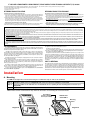
B. Wiring
120V AC
Internal View
of the LDB-2
12V DC
Adapter
Included
JP1
JP2
1
2
3
4
5
6
7
8
9 10
To C.O. Line or Analog
PABX/KSU Extension
Auxiliary 12V DC Output
To Phone (only required
for loop detection)
Relay Contact (pins 7 & 8)
Relay Contact (pins 5 & 6)
!
IMPORTANT: Electronic devices are susceptible to lightning and power station electrical surges from both the AC outlet and
the telephone line. It is recommended that a surge protector be installed to protect against such surges. Contact Panamax
at (800) 472-5555 or Electronic Specialists Inc. at (800) 225-4876.
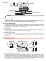
C. Ring Detection Only
Connect the incoming line to terminal block positions 1 and 2, as shown in the diagram to the right. No terminal device
is required. In this manner, the LDB-2 can monitor for ringing any place along the ringing line.
D. Ring and Loop Detection
If the application requires loop as well as ring detection, the LDB-2 must be placed between the phone line and the
terminal device to be monitored. Connect the incoming line to terminal block positions 1 and 2 and connect the terminal device to positions 3 and 4, as shown in the diagram above.
E. Relay Contacts
Relay contacts are available at terminal block positions 5,6 and 7,8. If the contacts are driving an inductive load, be
sure to place a suppression device at the load to snub any high voltage spikes.
F. Auxiliary 12V DC Output
12V DC is available for low current applications. The positive side is available at terminal position 10, and the negative
side is at position 9. Once all the line and load connections have been made, plug in the 120 V AC wall adapter, and
replace the cover.
Programming
JP1
Relay Closure
Time Out
Internal View of the LDB-2
or
N/O
N/C
R2
JP2
JP1
JP2
Remove R2 to Disable
Ring Detection
1
2
3
4
5
6
7
8
or
9 10
N/O
N/C
A. Adjustable Relay Closure Time Out
The time out POT (see diagram above) can be adjusted from 2 to 6 seconds. Turn the time out POT counter clockwise to decrease the closure time. Turn it clockwise to increase the closure time. When monitoring for ring, turning the
time out POT fully counter clockwise will allow the relay closure to follow standard ring cadence, turning it fully clockwise will allow the relay closure to be maintained during the entire off time of the ring signal. When monitoring for loop,
the relay closure will be maintained while off-hook and will time out following an on-hook.