1
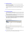
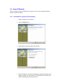
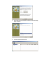
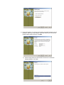
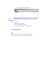
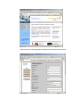
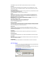
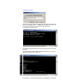
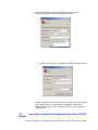
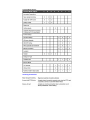
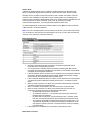
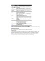
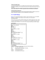
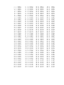
NetPort User Guide
Version: v1.0 April 2006
Contents
Contents..............................................................................................................................................2
1 Introduction ..................................................................................................................................3
2 What's in the Box .........................................................................................................................4
3 Connecting NetPort......................................................................................................................5
4 Configuring NetPort......................................................................................................................6
What you need to know before you start......................................................................................... 8
4.1
Install DeviceInstaller ........................................................................................................... 9
4.2
Running DeviceInstaller ....................................................................................................... 9
4.3
Assign IP Manually............................................................................................................. 10
4.3.1
If the NetPort is shown in DeviceInstaller: ....................................................................10
4.3.2
If the NetPort is NOT shown in DeviceInstaller: ...........................................................12
4.4
Changing NetPort’s Serial Parameters to connect to your Equipment ............................... 14
4.4.1
Via Web Interface ........................................................................................................14
4.4.2
14
4.4.3
Via Telnet.....................................................................................................................17
4.4.4
Via Serial Port (master config port) ..............................................................................19
5 Sending/Receiving data .............................................................................................................21
5.1
If you do NOT have an application which can talk to a TCP/IP Socket............................... 21
5.2
If you have an application already which can talk to a TCP/IP Socket ............................... 22
6 Appendix A – Setup Mode Parameters ......................................................................................24
6.1
Accessing Setup Mode ...................................................................................................... 24
6.2
Server Configuration (Network Configuration).................................................................... 26
6.2.1
IP Address ...................................................................................................................26
6.3
Channel 1 Configuration (Serial Port Parameters) ............................................................. 27
6.3.1
Baudrate ......................................................................................................................28
6.4
E-mail Settings................................................................................................................... 37
6.5
Expert Settings................................................................................................................... 38
6.6
Security Settings ................................................................................................................ 39
6.6.1
Encryption Tutorial .......................................................................................................41
6.7
Factory Defaults................................................................................................................. 42
7 Appendix B - Using Monitor Mode..............................................................................................43
7.1.1
Via the Serial Port ........................................................................................................43
7.1.2
Via a Telnet Connection...............................................................................................43
8 Appendix C - Reloading Firmware..............................................................................................44
8.1.1
Using TFTP..................................................................................................................45
8.1.2
Using the Serial Port with DeviceInstaller.....................................................................45
9 Appendix D – Hexadecimal Table ..............................................................................................45
1 Introduction
This User Guide provides a familiarisation tool to allow you to get your NetPort connected
and get your RS232 equipment on the network as quickly as possible. It will take you step
by step through hardware setup and configuration and help you verify that everything is
working.
What this document will help you achieve:
1) Familiarise you with NetPort & the contents of the kits.
2) Connect NetPort to the LAN.
3) Install Device Installer from the CDROM and use it to detect your NetPort.
4) Assign an IP address to your NetPort so you can consistently reach it.
5) Change the serial settings in NetPort to match those of your serial
equipment.
6) Make a successful connection and transfer data!
If you require more information than this User Guide covers, here are some options:
Data:
www.alphamicro.net/netport
Technical info & FAQ’s: www.alphamicro.net/netport/FAQ ** CONSTANTLY UPDATED **
Technical assistance:
[email protected]
Note: This document covers NetPort device server versions AMC232LAN01 &
AMC232LAN01-DVK but the same knowledge can be applied to all the AMC232LAN01-06
products.
2 What's in the Box
AMC Part Number
AMC-232LAN01
AMC-232LAN01-DVK
AMC-232LAN01-DVK/E
AMC-232LAN01-DVK/U
Comments
NetPort bulk version
Complete DTE kit
Complete DTE kit
Complete DTE kit
Type
DTE
AMC-232LAN02
AMC-232LAN02-DVK
AMC-232LAN02-DVK/E
AMC-232LAN02-DVK/U
NetPort bulk version
Complete DCE kit
Complete DCE kit
Complete DCE kit
DCE
AMC-232LAN03
AMC-232LAN03-DVK
AMC-232LAN03-DVK/E
AMC-232LAN03-DVK/U
NetPort encrypted bulk version
Complete DTE encrypted kit
Complete DTE encrypted kit
Complete DTE encrypted kit
DTE
AMC-232LAN04
AMC-232LAN04-DVK
AMC-232LAN04-DVK/E
AMC-232LAN04-DVK/U
NetPort encrypted bulk version
Complete DCE encrypted kit
Complete DCE encrypted kit
Complete DCE encrypted kit
DCE
AMC-232LAN06
AMC-232LAN06-DVK
AMC-232LAN06-DVK/E
AMC-232LAN06-DVK/U
NetPort bulk + DBP power feed
Complete kit + DB9 power feed
Complete kit + DB9 power feed
Complete kit + DB9 power feed
DTE
DTE
DCE
DTE
DCE
DTE
PSU
UK
Euro
USA
CD
Packaging
Bubble wrapped
Cardboard carton
Bubble wrapped
UK
Euro
USA
Cardboard carton
Bubble wrapped
UK
Euro
USA
Cardboard carton
Bubble wrapped
UK
Euro
USA
Cardboard carton
Bubble wrapped
UK
Euro
USA
Cardboard carton
Type
DTE (Data Terminal Equipment) versions behave similarly to a PC Com Port and are regarded as
the Masters in an RS232 connection. They are equipped with 200mm DB9 cables terminated with
plugs (pins).
DCE (Data Communications Equipment) versions behave similarly to a modem and are regarded as
the Slaves in an RS232 connection. They are equipped with 200mm DB9 cables terminated with
sockets.
PSU
The PSU provided with the DVK’s are:
UK versions
European versions
USA versions
AMCPS046A
AMCPS080
AMCPS081
220v to 9v DC @ 600mA unregulated
220v to 9v DC @ 600mA unregulated
110v to 9v DC @ 600mA unregulated
….and can be ordered separately should you application require. This unit supplies 9v DC
(unregulated) at up to 600mA thus allowing more than one NetPort or piece of equipment to be
powered at once.
With LAN06, this PSU can be used to power NetPort and the RS232 equipment but please check
compatibility of your RS232 equipment before applying power to LAN06 versions.
NetPort can accept input voltages from 5v to 30v DC.
CDROM
The CDROM contains 2 software utilities that you will need for a successful installation as well as
this user guide and various Applications Notes. It is free from licenses and therefore can be readily
distributed to installers and end users if needed. Alternatively, all the content of the CD is available
at www.alphamicro.net/netport.
Custom versions of NetPort
The above list is not exhaustive and customisation of NetPort to suit customer’s requirements is
available. Minimum order quantities for customisation will apply.
3 Connecting NetPort
To get started, you must connect the NetPort to your network. Follow the steps
below:
Note: This procedure assumes that the PC is connected to the network.
You may connect a crossover Ethernet cable directly between the PC and
NetPort if a network is not available but you will need to fix the IP address
of both PC & NetPort for consistent operation.
The final setup should look like this:
Ethernet Hub
or Switch
V
e
Your rRS232
Equipment
i
f
i
c
a
t
i
o
PSU
n
NETWORK
C
h
e
c
k
:
If powered up correctly, the NetPort power LED will light yellow and
remains on. This LED is on the RS232 end.
Verification Check 2: If the Ethernet Port on NetPort has authenticated
with the LAN successfully then the LED’s will confirm the speed and
connect mode according to the RHS section of the diagram below:
Internal 3v3 Power
Yellow = ON
RS232 connection
Green = connected
RS232 End
Ethernet Link
Green=100Mb/s
Yellow=10Mb/s
Ethernet Activity (flash)
Green=Full Duplex data flow
Yellow=Half Duplex data flow
Network End
PC
4 Configuring NetPort
The next sections will help you to carry out the following:
• Identify the NetPort on your LAN
• Allocate an IP address to your NetPort
• Set up a ‘serial tunnel’ from the network to the NetPort
• Change settings in NetPort to make it compatible with your serial equipment.
The following diagram may help you to establish what decisions you need to make and the
appropriate action to get things running as quickly as possible:
Deciding the best routes
to getting connected
Power up NetPort on your LAN
Do you want to run
NetPort with a FIXED
IP addresss?
No
Yes
(this means the IP could change
over time)
Do you know the
temporary IP address that
NetPort is currently on?
No
No
Can you run Device
Installer on a PC on the
LAN to detect NetPort?
Use Monitor Mode
to establish
NetPort's IP
Address
Can you access the
RS232 Port and connect
to a PC or Terminal?
Yes
Yes
Yes
Access to a web
browser?
No
No
Yes
RS232
DEVICE
WEB
TELNET
SESSION INSTALLER
MANAGER
RS232
DEVICE
WEB
TELNET
SESSION INSTALLER
MANAGER
Detect NetPort's IP Address
Fix NetPort's IP address
Load Redirector on your
Windows PC/Server
No
No
Are you running
Redirector V3 or
later?
Yes
Configure Redirector
to use Port 3001
Access to a
web browser?
Can you access
No
NetPort's RS232
Port and connect it
to a PC or
Terminal?
No
Yes
Yes
Can you access
NetPort's RS232
Port and connect it
to a PC or
Terminal?
Access to a
web browser?
Yes
No
No
RS232
DEVICE
WEB
TELNET
SESSION INSTALLER
MANAGER
RS232
DEVICE
WEB
TELNET
SESSION INSTALLER
MANAGER
Check NetPort Local Port = 14001
Check NetPort Local Port = 10001
Do you need to change
the Serial Port settings in
NetPort to match your
equipment?
Yes
RS232
DEVICE
WEB
TELNET
SESSION INSTALLER
MANAGER
Change NetPort Serial port settings
Make your connection
Changing NetPort to suit your
equipment
No
Changing NetPort to suit the
connection
No
Use WINSOCK or Direct
Socket method
Configure Redirector
to use Port 10001 and
enable Raw Mode
Establishing the connection mode
Using Redirector to
provide a Virtual Com Port
that magically connects to
NetPort?
Yes
Yes
Establishing the IP Address
Dynamic IP address
allocated by a DHCP Server
What you need to know before you start
IP Address
Your NetPort must have a unique IP address on your network.
The system administrator generally provides the IP address, subnet mask, and gateway or they will
opt for it to be allocated by the DHCP Server dynamically each time it is powered up – consequently it
can change.
The IP address must be within a valid range, unique to your network, and in the same subnet as your
PC, check with your IT administrator for appropriate addresses.
IP Address:
_______________________________________
Subnet Mask: _______________________________________
Gateway
_______________________________________
Hardware Address
You may need to know the unit's hardware address (also known as a MAC address). On later
NetPorts this is printed on the white label which is fixed to the underside of the unit. Earlier NetPorts
did not have this label so you may need to use Device Installer to detect this MAC address and write
it down if required.
The format is: 00-20-4a-XX-XX-XX, where XXs are unique numbers assigned to the product.
Assigning IP Addresses
The unit's IP address is set to 0.0.0.0 at the factory which established it in DHCP Client mode and will
attempt to obtain an IP address, Subnet & Gateway from a DHCP Sever.
You have several options for manually assigning an IP to your unit. We recommend that you connect
the NetPort to the network and assign the IP address using DeviceInstaller, which is on the NetPort
CDROM.
4.1 Install DeviceInstaller
1. Install DeviceInstaller from the CD-ROM. If the CD does not launch automatically browse the ‘Device
Installer’ folder and run the setup.EXE file
2. Respond to the installation wizard prompts. You may be prompted to install .NET frameworks
to bring your Windows installation up to date to be able to run DeviceInstaller. These are
provided on the CDROM but your PC may choose to (or already done so) download from
Microsoft.
Note: For more information about DeviceInstaller, see the DeviceInstaller help menus.
4.2 Running DeviceInstaller
1.
Click Start\Programs\Lantronix\Devicelnstaller. If your PC has more than one network
adaptor, a message displays. Select the adaptor that the NetPort will be attached to and click
OK.
2.
Press Search to detect NetPorts on the network. If the Search window reveals ‘No Devices
Found’, press Search again until your NetPort is shown. You may need to wait for up to 30
seconds for all NetPorts to be shown, keep pressing Search.
Note: If the unit cannot find a DHCP Server to obtain an address then it will default into AutoIP
mode, assuming an IP address in the region 169.254.xxx.xxx and show in DeviceInstaller in
red. In some cases re-applying power to the Netport will allow it to enumerate on your
network successfully. If the Network has no DHCP Server then you will have to set the IP
address manually. See section: 4.3 Assign IP Manually
You should see something like this:
By selecting the relevant NetPort you are then able to change the configuration via 2 methods, choose
whichever suits you:
•
Telnet (ASCII menus over the network)
•
Web Config (via any web browser)
Note: It is also possible to configure NetPort via the RS232 port using an application such as
HyperTerminal. See section: 4.4.4 Via Serial Port (master config port)
4.3 Assign IP Manually
There are 2 ways to achieve this depending on whether or not you have successfully detected
NetPort using Device Installer.
4.3.1 If the NetPort is shown in DeviceInstaller:
1.
Select the NetPort to be modified
2.
Click the Assign IP icon.
3. Select Assign a specific IP address and click Next.
4. Enter the IP address. The Subnet mask displays automatically based on the IP
address; if desired, you may change it. On a local network, you can leave the
Default Gateway blank (all zeros). Click Next.
5. Click the Assign button and wait several seconds until a confirmation message
displays. Click Finish.
6. You should see NetPort displayed like this:
4.3.2 If the NetPort is NOT shown in DeviceInstaller:
1) Click on Assign IP
2) When prompted, enter the hardware address in the format 00-204a-XX-XX-XX, where the XXs are unique numbers assigned to each individual
product. Click Next.
3) Select Assign a specific IP Address
4) Enter the IP address. The Subnet mask displays automatically based on the IP
address; if desired, you may change it. On a local network, you can leave the
Default gateway blank (all zeros). Click Next.
5) Click the Assign button and wait several seconds until a confirmation
message displays. Click Finish.
6) You should see NetPort shown similar to this:
4.4
Changing NetPort’s Serial Parameters to connect to your
Equipment
To do this you can use:
•
Web Config (via any webrowser)
•
Telnet (ASCII menus over the network)
•
RS232 port using an application such as HyperTerminal.
4.4.1 Via Web Interface
4.4.2
Open a browser on a computer on a compatible Subnet as the NetPort.
Enter the IP Address of the NetPort into the browser and press ENTER.
Within 5 seconds a Java-based applet will upload into the browser and look like this:
Change the relevant settings for your needs. Here are some of the most commonly used
parameters:
In the Server Properties page:
IP Address:
The unique address that the NetPort resides at. Over type this field to fix the IP Address –
this may mean that it is incompatible with other LAN’s that it is subsequently connected to.
Leave as 0.0.0.0 for DHCP (dynamically allocated by the DHCP Server on your LAN) but be
aware that the IP Address could change over time as the DHCP Server refreshes this.
Subnet mask:
Defines the range of IP Addresses that this device has access to and vice versa. In a typical
Class C Private Network using the range 192.168.0.x the subnet will be 255.255.255.0 (or 8
bit). Leave as 0.0.0.0 for DHCP allocated.
Gateway:
If the NetPort is expected to establish connection outside of the Firewall/Gateway that belongs
to the LAN you will need to tell it which Gateway to use. Leave as 0.0.0.0 for DHCP allocated.
High Performance
ONLY enable if you need the NetPort to run at RS232 speeds of 460kbps & 920kbps.
Telnet Password
Only update this field if you wish to apply a password to Telnet sessions to the device (all
ports)
In the Port Properties page
Speed
NetPort port speed which needs to match the speed of your RS232 device
Flow Control
Select CTS/RTS for automatic hardware flow control of buffered data (factory default) Note:
CTS/RTS are not manually controllable over the LAN.
Select Xon/Xoff for software flow control of buffered data
Select None for simple 3 wire UART connection where flow control is not necessary
Local Port
This is the TCP/IP Port that NetPort uses for the data in & out of the RS232 port. In most
cases set this to 10001 for a standard connection. (older units may be factory set to 10001)
Incoming Connection
Select Connect with DTR if you want an incoming connection only to be permitted when DTR
is asserted by your RS232 equipment.
Select Unconditional to accept all incoming connections
Startup
Select the appropriate option if you want an outgoing connection to be established under
certain criteria. In most cases you will need to enter a Remote Host & Remote Port in the
field below to tell NetPort what to connect to.
Modem Mode allows you to dial an IP address manually from NetPort’s RS232 port via an
interface that mimics a basic modem AT command line. For example:
Type: ATDT 192.168.0.1, 10001
Reply is either: CONNECT (and you are in transparent mode)
Or NO CARRIER (and you remain in command line mode)
ATH or +++ to exit transparent mode.
Remote IP Address
In cases when you want NetPort to initiate the connection, specify the IP Address of the target
device here. Note: if you are attaching to a device behind a firewall, you may need to add an
entry into the routing table to reach the remote device.
Remote Port
Specify the remote TCP/IP port of the device you wish NetPort to connect to. This port
number does not have to be the same as that set inside NetPort, thus allowing connections to
equipment other than NetPort’s.
Flush Mode
Controls whether you want to flush the contents of any buffers upon a new connection or
preserve them.
Packing Algorithm
Can be used to avoid fragmentation of your data should packetisation cause data corruption.
Telnet Mode
Allows you to Telnet into the RS232 port of NetPort if enabled. Switch off if not used as it will
filter certain bytes from your data.
Port Password
If enabled requires the Telnet Password to be entered before a connection is authorised.
4.4.3 Via Telnet
Note. If you or any other user has disabled Telnet previously inside NetPort then
this option will not be available until it is re-enabled.
You can use the Quick Link Icon in Device Installer to enter Telnet config or you
can run Telnet form a command line or windows shell.
Quick Link example
Command Line example
In any event, you must specify Port 9999 as the destination port to be able to
enter the configuration menus. Telnetting to port 10001 will result in you
connecting to the RS232 port of NetPort and not the config menus.
Once Telnet has established a link:
You will need to press ENTER within 3 seconds or NetPort will time out and close
the session.
Once the session has begun NetPort will scroll through all of its config in an
ASCII format and then offer an ASCII menu.
See Appendix A – Setup Mode Parameters for a full breakdown of the options
and hexadecimal masks.
In Summary:
To change IP address, Gateway, Subnet and DHCP name (where applicable)
use Menu 0
To change the serial settings (baud rate handshaking etc) use Menu 1
To change the Local Port, Remote IP address & Remote Port use Menu 1
To enable or disable telnet, HTTP, SNMP, TFTP & passwords use Menu 6
To restore factory default settings (except IP address/subnet/Gateway) use
Menu 7
Tip: Press ENTER to move through the menu fields without changing them.
Top-tip: Ensure you save any changes made in the above by selecting Menu 9
☺
4.4.4 Via Serial Port (master config port)
The RS232 port is always enabled and is therefore the master config port. To
access the config menus you will need to establish a serial session using a PC or
Terminal.
1. For a PC, connect as follows:
Connect NetPort to the COM
Port of the PC.
PC
PSU
LAN01 & LAN06 variants will
require a null modem cable to
transpose the TX/Rx wires as
both the PC & LAN01 are DTE
devices. A null modem cable in
its simplest form connects the
GND (pin 5) and crosses the Tx
(pin 3) and Rx (pin 2) wires over.
LAN02 variants will connect
directly to the COM Port.
DO NOT POWER THE NETPORT YET
2. On the PC, run a Terminal Application such as HyperTerminal, MTTY or
similar. Set the Application to connect with the following settings:
9600bps, No parity, 8 bit data, 1 stop bit, no handshaking
3. Once the Application is running, power up the NetPort and hold down the ‘x’
key on the PC until you receive the following prompt:
Note: If the CAPS lock is enabled on your keyboard NetPort will not respond.
Turn off CAPS Lock, turn off power to NetPort and repeat the above.
4. You will need to press ENTER within 3 seconds or NetPort will time out and
close the session.
5. Once the session has begun NetPort will scroll through all of its config in an
ASCII format and then offer an ASCII menu.
See Appendix A – Setup Mode Parameters for a full breakdown of the options
and hexadecimal masks.
In Summary:
To change IP address, Gateway, Subnet and DHCP name (where applicable)
use Menu 0
To change the serial settings (baud rate handshaking etc) use Menu 1
To change the Local Port, Remote IP address & Remote Port use Menu 1
To enable or disable telnet, HTTP, SNMP, TFTP & passwords use Menu 6
To restore factory default settings (except IP address/subnet/Gateway) use
Menu 7
Tip: Press ENTER to move through the menu fields without changing them.
Top-tip: Ensure you save changes made in the above by selecting Menu 9 ☺
5
Sending/Receiving data
The NetPort should now be enumerated on your LAN and can receive/send data according to
its standard serial settings:
•
•
9600b/sec, No parity, 8 bit data, 1 stop bit
Handshaking set to CTS/RTS
If your RS232 equipment can communicate in this data format then all you need to do now is
open an application on a networked PC to send/receive.
5.1
If you do NOT have an application which can talk to a TCP/IP
Socket.
You have 2 options without creating a specific software application:
1. Use Com Port Redirector to assign a Virtual Com Port to the NetPort, you can then
use your existing application software to communicate via COMx over the Ethernet
without any TCP/IP knowledge. (where x is the Com Port number you have
configured in Redirector)
a) Install Com Port Redirector on the PC that the Virtual Com Port is required
using the NetPort CDROM.
b) Run Redirector by clicking
Start\Programs\Lantronix\Redirector\Configuration.
See the AMC-AN-LAN07 Com Port Redirector Apps Note Iss01.pdf on the CDROM
for more help.
Redirector config Notes: When configuring the TCPPort, enter a value of 10001,
ensure Raw Mode is enabled in Port Settings.
Note: At the time of going to press, NetPort is factory set to Local Port = 14001 and
will need changing by the user to 10001. See section: 4.4 Changing NetPort’s Serial
Parameters to connect to your Equipment
2. Use HyperTerminal-32bit (included in Windows Xp & Windows 2000) in Winsock
mode to connect over the Ethernet to the NetPort.
Note: At the time of going to press, NetPort is factory set to Local Port = 14001 and
will need changing by the user to 10001. See section: 4.4 Changing NetPort’s Serial
Parameters to connect to your Equipment
•
•
Run HyperTerminal from the Accessories\Communications menu.
Select TCP/IP (Winsock) mode from the pull-down menu.
•
Enter the IP Address of your NetPort and 10001 for the port number:
If HyperTerminal does not successfully connect, check that you have entered
the IP address and Port number correctly. Additionally, check that the
NetPort settings match the baud rate and port number you have entered in
HyperTerminal.
5.2
Socket
If you have an application already which can talk to a TCP/IP
You need to configure your Application to use Socket (Port) number 10001 and ensure this is
the same inside NetPort.
To do this you can use:
•
Telnet (ASCII menus over the network)
•
Web Config (via any webrowser)
•
RS232 port using an application such as HyperTerminal.
Note: At the time of going to press, NetPort is factory set to Local Port = 14001 and will need
changing by the user to 10001. See section: 4.4 Changing NetPort’s Serial Parameters to
connect to your Equipment
6
Appendix A – Setup Mode Parameters
The following is the raw breakdown of the Setup Mode Parameters that
apply to NetPort.
You can enter Setup Mode using the following procedures locally or remotely:
• Use a Telnet connection to configure the unit over the network.
• Use a terminal/emulation program to access the serial port locally.
•
The unit’s configuration is stored in nonvolatile memory and is retained without power. You
can change the configuration at any time. The unit performs a reset after the configuration has
been changed and stored.
Note: The menus in this section show a typical device. Your device may have different
configuration options.
6.1 Accessing Setup Mode
Using a Telnet Connection
To configure the unit over the network, establish a Telnet connection to port 9999.
Note: You can also use DeviceInstaller to access Telnet. Select the device from the main
window list, and click the Telnet icon. If you use the Telnet icon on the DeviceInstaller
toolbar, skip steps 1 and 2.
1. From the Windows Start menu, click Run and type the following command, where
x.x.x.x is the IP address, and 9999 is the unit’s fixed network configuration port
number:
telnet x.x.x.x 9999
Note: Be sure to include a space between the IP address and 9999.
2. Click OK. The following information displays.
MAC Address
3. To enter the Setup Mode, press Enter within 5 seconds. The configuration settings
display, followed by the setup menu options.
Setup Menu Options
4. Select an option on the menu by entering the number of the option in the Your
choice? field and pressing Enter.
5. To enter a value for a parameter, type the value and press Enter, or to confirm a
current value, just press Enter.
6. When you are finished, save the new configurations (option 9). The unit reboots.
Using the Serial Port
To initially configure the unit through a serial connection:
1. Connect a console terminal or PC running a terminal emulation program to your unit's
serial port. The default serial port settings are 9600 baud, 8 bits, no parity, 1-stop bit, noflow control.
2. To enter Setup Mode, reset the unit by cycling the unit's power (power off and back on).
The self-test will begin. You have one second to enter three lowercase x characters
(xxx).
Note: The easiest way to enter Setup Mode is to hold down the x key at the terminal (or
emulation) while resetting the unit.
3. At this point, the screen display is the same as when you use a Telnet connection
The following figure shows all of the configuration parameters. The remainder of this Appendix
describes each parameter in detail.
6.2 Server Configuration (Network Configuration)
The unit’s basic network parameters display when you select Server configuration (option
0). The IP Address, Set Gateway IP Address, and Netmask fields display the current
values.
Server Configuration Parameters
6.2.1 IP Address
The IP address must be set to a unique value in your network.
Set Gateway IP Address
The gateway address, or router, allows communication to other LAN segments. The gateway
address should be the IP address of the router connected to the same LAN segment as the
unit. The gateway address must be within the local network. The default is N (No), meaning
the gateway address has not been set. To set the gateway address, type Y and enter the
address.
Netmask: Number of Bits for Host Part
A Netmask defines the number of bits taken from the IP address that are assigned for the host
section.
Note: Class A: 24 bits; Class B: 16 bits; Class C: 8 bits
The unit prompts for the number of host bits to be entered, then calculates the Netmask,
which displays in standard decimal-dot notation when the saved parameters are displayed (for
example, 255.255.255.0).
Change Telnet Configuration Password
Setting the Telnet configuration password prevents unauthorized access to the setup menu
via a Telnet connection to port 9999 or via web pages. The password must have 4 characters.
An enhanced password setting (for Telnet access only) of 16 characters is available under
Security Settings.
Note: You don’t need a password to access the Setup Mode window via a serial connection.
DHCP Name
If a DHCP server has automatically assigned the IP address and network settings, you can
discover the unit by using the DeviceInstaller network search feature. There are three
methods for assigning DHCP names to the unit.
• Default DHCP Name: If you do not change the DHCP name, and you are using an IP
of 0.0.0.0, then the DHCP name defaults to CXXXXXX (XXXXXX is the last 6 digits of
the MAC address shown on the label on the bottom/side of the unit). For example, if
the MAC address is 00-20-4A-12-34-56, then the default DHCP name is C123456.
• Custom DHCP Name: You can create your own DHCP name. If you are using an IP
address of 0.0.0.0, then the last option in Server configuration is:
•
•
Change DHCP device name. This option allows you to change the DHCP name to
an alphanumeric name (LTX in our example).
Numeric DHCP Name: You can change the DHCP name by specifying the last octet
of the IP address. When you use this method, the DHCP name is LTXYY where YY is
what you chose for the last octet of the IP address. If the IP address you specify is
0.0.0.12, then the DHCP name is LTX12. This method only works with 2 digit
numbers (0-99).
6.3 Channel 1 Configuration (Serial Port Parameters)
Using this option, define how the serial port will respond to network and serial
communications.
Note: You must enter some values in hexadecimal notation.
Default Serial Port Settings are:
6.3.1 Baudrate
The unit and attached serial device, such as a modem, must agree on a speed or baud rate to
use for the serial connection. Valid baud rates are 300, 600, 1200, 2400,
4800, 9600 (default), 19200, 38400, 57600, 115200, and 230400 bits per second. In standard
Clock Mode. The unit also supports high-performance baud rates of 460800, and 921600 bits
per second (see Expert Settings to configure High Performance Mode to attain these speeds).
I/F (Interface) Mode
The Interface (I/F) Mode is a bit-coded byte entered in hexadecimal notation.
Interface Mode Options
(1) 2 stop bits are implemented by the software. This might influence performance.
The following table demonstrates how to build some common Interface Mode settings:
Common Interface Mode Settings
Flow
Flow control sets the local handshaking method for stopping serial input/output. Use the
following table to select flow control options:
Flow Control Options
Port Number
The setting represents the source port number in TCP connections. It is the number that
identifies the channel for remote initiating connections. The default setting for Port 1 is 10001.
The range is 1-65535, except for the following reserved port numbers:
Reserved Port Numbers
Warning: We recommend that you not use the reserved port numbers for this setting as
incorrect operation may result.
The port number functions as the TCP/UDP source port number for outgoing packets.
Packets sent to the unit with this port number are received to this channel.
The port number selected is the Incoming TCP/UDP port and Outgoing TCP/UDP source port.
Use Port 0 when you want the outgoing source port to change with each connection. If the
port number is 0, a random value of at least 50000 is used to actively establish a connection.
Each subsequent connection increments the number by 1. When the port number reaches
59999, it wraps around to 50000.
Only use the automatic port increment feature to initiate a connection using TCP. Set the port
to a non-zero value when the unit is in a passive mode or when you are using UDP instead of
TCP.
Connect Mode
Connect Mode defines how the unit makes a connection, and how it reacts to incoming
connections over the network. Enter Connect Mode options in hexadecimal notation.
Connect Mode Options
Incoming Connection
Response
Manual Connection Address Example
Autostart (Automatic Connection)
To enable the hostlist:
1)
2)
3)
4)
5)
6)
Enter a Connect Mode of 0x20 (2X), where X is any digit. The menu shows you
A list of current entries already defined in the product.
To delete, modify, or add an entry, select Yes. If you enter an IP address of 0.0.0.0, that entry and all
others after it are deleted.
After completing the hostlist, repeat the previous step if necessary to edit the hostlist again.
For Retrycounter, enter the number of times the Lantronix unit should try to make a good network
connection to a hostlist entry that it has successfully ARPed. The range is 1-15, with the default set to 3.
For Retrytimeout, enter the number of seconds the unit should wait before failing an attempted connection.
The time is stored as units of milliseconds in the range of 1-65535. The default is 250.
Datagram Type
Modem Mode
In Modem (Emulation) Mode, the unit presents a modem interface to the attached serial
device. It accepts AT-style modem commands, and handles the modem signals correctly.
Normally, there is a modem connected to a local PC and a modem connected to a remote
machine. A user must dial from the local PC to the remote machine, accumulating phone
charges for each connection. Modem Mode allows you to replace modems with NetPorts, and
to use an Ethernet connection instead of a phone call. By not having to change
communications applications, you avoid potentially expensive phone calls.
To select Modem Mode, set the Connect Mode to C6 (no echo), D6 (echo with full verbose),
or D7 (echo with 1-character response).
Note: If the unit is in Modem Mode, and the serial port is idle, the unit can still accept network
TCP connections to the serial port if Connect Mode is set to C6 (no echo), D6 (echo with full
verbose), or D7 (echo with 1-character response).
Modem Mode Messages
•
•
•
•
•
•
•
•
Received commands must begin with the two-character sequence AT and be
terminated with a carriage return character.
The unit ignores any character sequence received not starting with AT, and only
recognizes and processes single AT-style commands. The unit treats compound AT
commands as unrecognized commands.
If the Full Verbose option is in effect, the unit responds to an unrecognized command
string that is otherwise formatted correctly (begins with AT and ends with carriage
return) with the OK message and takes no further action.
If the 1-Character Response option is in effect, the unit responds to an unrecognized
command string that is otherwise formatted correctly with ‘1’ and takes no further
action.
When an active connection is in effect, the unit transfers data and does not process
commands received from the serial interface.
When a connection is terminated or lost, the unit reverts to command mode.
When an active connection is in effect, the unit terminates the connection if it
receives the following sequence from the attached serial device:
o No serial data is received for one second.
o The character sequence +++ is received, with no more than one second
between each two characters.
o No serial data is received for one second after the last + character. At this
time, the unit responds affirmatively per the selected echo/response mode.
o The character string ATH is received terminated with a carriage return. The
unit responds affirmatively according to the selected echo/response mode
and drops the network connection. The serial interface reverts to accepting
command strings.
If this sequence is not followed, the unit remains in data transfer mode.
Modem Mode Commands
Note: The unit recognizes these AT commands as single commands such as ATE0 or ATV1;
it does not recognize compound commands such as ATE0V.
Remote IP Address
This is the destination IP address used with an outgoing connection.
Remote Port
You must set the remote TCP port number for the unit to make outgoing connections. This
parameter defines the port number on the target host to which a connection is attempted.
Note: To connect an ASCII terminal to a host using the unit for login purposes, use the
remote port number 23 (Internet standard port number for Telnet services).
DisConnMode
This setting determines the conditions under which the unit will cause a network connection to
terminate.
Note: In DisConnMode (Disconnect Mode), DTR drop either drops the connection or is
ignored.
Disconnect Mode Options
Flush Mode (Buffer Flushing)
Using this parameter, you can control line handling and network buffers with connection
startup and disconnect. You can also select between two different packing algorithms.
Flush Mode Options
Function 7 6 5 4 3 2 1 0
Pack Control
Two firmware-selectable packing algorithms define how and when packets are sent to the
network. The standard algorithm is optimized for applications in which the unit is used in a
local environment, allowing for very small delays for single characters, while keeping the
packet count low. The alternate packing algorithm minimizes the packet count on the network
and is especially useful in applications in a routed Wide Area Network (WAN). Adjusting
parameters in this mode can economize the network data stream.
Pack control settings are enabled in Flush Mode. Set this value to 00 if you do not need
specific functions.
Pack Control Options
Packing Interval: Packing Interval defines how long the unit should wait before sending
accumulated characters. This wait period is between successive network segments containing
data. For alternate packing, the default interval is 12 ms.
Trailing Characters: In some applications, CRC, Checksum, or other trailing characters
follow the end-of-sequence character; this option helps to adapt frame transmission to the
frame boundary.
Send Characters: If 2-Byte Send Character Sequence is enabled, the unit interprets the
sendchars as a 2-byte sequence; if this option is not enabled, the unit interprets them
independently. If Send Immediately After Characters is not set, any characters already in the
serial buffer are included in the transmission after a "transmit" condition is found. If this option
is set, the unit sends immediately after recognizing the transmit condition (sendchar or
timeout).
Note: A transmission might occur if status information needs to be exchanged or an
acknowledgment needs to be sent.
DisConnTime (Inactivity Timeout)
Use this parameter to set an inactivity timeout. The unit drops the connection if there is no
activity on the serial line before the set time expires. Enter time in the format mm:ss, where m
is the number of minutes and s is the number of seconds. To disable the inactivity timeout,
enter 00:00. Range is 0 (disabled) to 5999 seconds (99 minutes, 59 seconds). Default is 0.
Send Characters
You can enter up to two characters in hexadecimal representation in sendchar. If the unit
receives a character on the serial line that matches one of these characters, it sends the
character immediately, along with any awaiting characters, to the TCP connection. This action
minimizes the response time for specific protocol characters on the serial line (for example,
ETX, EOT). Setting the first sendchar to 00 disables the recognition of the characters.
Alternatively, the unit can interpret two characters as a sequence (see Pack Control above).
Telnet Terminal Type
This parameter displays only if you enabled the terminal type option in Disconnect Mode. If
this option is enabled, you can use the terminal name for the Telnet terminal type. Enter only
one name.
If the terminal type option is enabled, the unit also reacts to the EOR (end of record) and
binary options, which can be used for applications like terminal emulation to IBM hosts.
Channel (Port) Password
This parameter appears only if the channel (port) password option is enabled in Disconnect
Mode. If the option is enabled, you can set a password on the serial port.
6.4 E-mail Settings
Note: You can change these settings via Telnet or serial connections only, not on the WebManager. To configure e-mail settings via DeviceInstaller, see the help files in
DeviceInstaller\Help.
The unit can send an e-mail to multiple recipients when a specific trigger event occurs. There
are three separate triggers, based on any combination of the configurable pins (GPIO) when
selected as user I/O functions. You can also use a two byte serial string to initiate a trigger.
E-mail Settings
E-mail Setup
E-mail setup requires you to set up the e-mail server location as follows:
Trigger Setup
A trigger event can occur when the unit receives two bytes of a specified sequence on the
serial port, or because of a specified combination of conditions on the configurable pins.
If the serial sequence is set to 00,00, the trigger is disabled. At the Serial Sequence prompt,
enter the ASCII Hex value. Example: A two byte sequence of 12 would be 0x31, 0x32.
If the configurable pins are all set to X (Don’t Care), then they are disabled. If both the serial
sequence and the configurable pins are disabled, the trigger is disabled.
Note: You can set the configurable pins to A = Active, I = Inactive, or X = Don’t Care. Active
can be set to Active Low or Active High. To change the configurable pins’ settings, you must
use DeviceInstaller or see Applications Note AMC-ANLAN012 on the CDROM for a web
browser method.
Each trigger is independent of the others. Each condition within an individual trigger must be
met before the unit will send the e-mail.
6.5 Expert Settings
Note: You can change these settings via Telnet or serial connections only, not on the WebManager. Only an expert should change these parameters. You must definitely know the
consequences the changes might have.
TCP Keepalive time in seconds
This option allows you to change how many seconds the unit will wait during a silent
connection before attempting to see if the currently connected network device is still on the
network. If the unit then gets no response, it drops that connection.
ARP Cache timeout in seconds
Whenever the unit communicates with another device on the network, it adds an entry into its
ARP table. The ARP Cache timeout option allows you to define how many seconds (1-600)
the unit will wait before timing out this table.
High CPU Performance mode
This option applies to NetPort Iss01 and greater units only. It allows you to increase the
CPU performance and utilize the higher baud rates on the serial interface (i.e. 460Kbps and
920Kbps). Increasing CPU performance requires more power and lowers the unit’s operating
temperature. The standard CPU performance mode supports up to 230400 baud.
Note: If baud rates of 460Kbps or 920Kbps are set and the high performance mode disabled,
the operation of the serial channel would be out of the specified error tolerance thereby
leading to inconsistent speed settings on the two ends of the serial channel.
Monitor Mode at Bootup
This option allows you to disable all entries into Monitor Mode during startup, except for the
‘xxx’ sequence. This prevents entry via ‘yyy’, ‘zzz’, ‘xx1’, and ‘yy1’ key sequences (only during
the bootup sequence). The default for Monitor Mode at Bootup is enabled. See Appendix B Using Monitor Mode for more info on Monitor Mode
HTTP Port Number
This option allows the configuration of the web server port number. The valid range is 165535. The default HTTP port number is 80.
SMTP Port Number
This option allows the configuration of the email port number. The valid range is from 165535. The default SMTP port number is 25.
Note: When configuring the HTTP or SMTP port number; take note of the ‘reserved’port
numbers on above.
6.6 Security Settings
You can change security settings via Telnet or serial connections only, not on the WebManager. We recommend that you set security over the dedicated network or over the serial
setup. If you set parameters over the network (Telnet 9999), someone else could capture
these settings.
Caution: Disabling both Telnet Setup and Port 77FE will prevent users from accessing all
setup menus from the network. Disabling Port 77FE also disables the Web & Device Installer
from configuring the device.
Security Settings
Disable SNMP
This setting allows you to disable the SNMP protocol on the unit for security reasons.
SNMP Community Name
This setting allows you to change the SNMP community name. Community name is a required
field for NMS to read or write to a device. The default setting is public. The name is a string of
1 to 13 characters.
Disable Telnet Setup
Note: If you choose to disable this option, keep in mind that disabling both Telnet Setup and
Port 77FE will prevent users from accessing any setup menu from the network.
This setting defaults to the N (No) option. The Y (Yes) option disables access to Setup Mode
by Telnet (port 9999). It only allows access locally via the web pages and the serial port of the
unit.
Disable TFTP Firmware Upgrade
This setting defaults to the N (No) option. The Y (Yes) option disables the use of TFTP to
perform network firmware upgrades. With this option, you can download firmware upgrades
over the serial port using Device Installer’s Recover Firmware procedure. (See Appendix C Reloading Firmware.)
Disable Port 77FE (Hex)
Note: If you choose to disable this option, keep in mind that disabling both
Telnet Setup and Port 77FE will prevent users from accessing any setup menu from the
network.
Port 77FE is a setting that allows DeviceInstaller, Web-Manager, and custom programs to
configure the unit remotely. You may wish to disable this capability for security purposes.
The default setting is the N (No) option, which enables remote configuration. You can
configure the unit by using DeviceInstaller, web pages, Telnet, or serial configuration.
The Y (Yes) option disables remote configuration and web sites.
Note: The Y (Yes) option disables many of the GUI tools for configuring the unit, including the
embedded Web-Manager tool.
Disable Web Server
This setting defaults to the N (option). The Y (Yes) option disables the web server.
Disable ECHO Ports
This setting controls whether the serial port echoes characters it receives.
Enable Encryption
This option displays only if you purchased the encrypted versions of NetPort (LAN03 or
LAN04)). You can enable or disable (default) Rijndael encryption. Rijndael is the block cipher
algorithm recently chosen by the National Institute of Science and Technology (NIST) as the
Advanced Encryption Standard (AES) to be used by the US government.
To enable encryption, select the key length (128, 192 or 256 bits) and enter the encryption
key in hexadecimals (32, 48, or 64, respectively). The hexadecimals are echoed as asterisks
to prevent onlookers from seeing the key.
Figure 4-10. Encryption Keys
Encryption only applies to the port selected for tunneling (default 10001), regardless of
whether you are using TCP or UDP.
Generally, one of two situations applies.
• Encrypted NetPort-to-NetPort communication (and in the future, NetPort
communication to other Lantronix device servers) is supported without extra effort.
•
The NetPort uses standard AES encryption protocols. To communicate successfully,
products and applications on the peer side must use the same protocols and the
same shared key as the NetPort. To ease the development process, Alpha Micro can
provide an AES encryption DLL for Windows and protocol source code samples.
Please contact [email protected]
•
The following export agreement is required for the optional encryption:
I agree that I will not export or re-export this software file to a national resident of
Cuba, Iran, Iraq, Libya, North Korea, Sudan, Syria or any other country to which the
United States has embargoed goods; or to anyone on the US Treasury Department's
list of Specially Designated Nationals and Blocked Persons, US Commerce
Department's Table of Denial Orders and Entitles List, or the US State Department's
Debarred List. By receiving this software, I am agreeing to the foregoing and I am
representing and warranting that I am not located in, under the control of, or a national
or resident of any such country or on any such list.
6.6.1 Encryption Tutorial
Rijndael is the block cipher algorithm chosen by the National Institute of Science and
Technology (NIST) as the Advanced Encryption Standard (AES) to be used by the US
government. NetPort supports 128, 192 and 256 bit encryption key lengths. Follow the steps
below to configure AES encryption on the XPort.
Note: Configuring encryption should be done through a local connection to the serial port of
the NetPort, or via a secured network connection. Initial configuration information including the
encryption key is sent in clear text over the network.
1. Telnet to the configuration port on the NetPort (Port 9999).
Example Telnet command syntax is shown below. In the command examples below,
replace the x's with the IP address of the XPort.
Microsoft Windows command syntax: telnet xxx.xxx.xxx.xxx 9999
UNIX command syntax: telnet xxx.xxx.xxx.xxx:9999
2. When prompted, press Enter to go into Setup Mode.
3. At the Change Setup menu, select option 6 for security.
4. When prompted to enable encryption, press Y.
5. Enter the encryption key length when prompted. XPort supports 128-, 192- and
256-bit encryption key lengths.
6. When prompted to change keys, press Y.
7. At the Enter Keys prompts, enter your encryption key. The encryption keys are entered in
hexadecimal. The hexadecimal values are echoed as asterisks to prevent onlookers from
seeing the key. Hexadecimal values are 0-9 and A-F.
For a 128-bit key length, enter 32 hexadecimal characters.
For a 192-bit key length, enter 48 hexadecimal characters.
For a 256-bit key length, enter 64 hexadecimal characters.
8. Continue pressing Enter until you return to the Change Setup menu.
9. At the Change Setup menu, select option 9 to save and exit.
Enable Enhanced Password
This setting defaults to the N (No) option, which allows you to set a 4-character password that
protects Setup Mode by means of Telnet and web pages. The Y (Yes) option allows you to set
an extended security password of 16-characters for protecting Telnet and Web Page access.
Disable Port 77F0 (Hex)
Port 77F0 is a setting that allows a custom application to query or set the three NetPort
configurable pins (factory set to CTS/RTS/DTR) when they are functioning as general purpose
I/O (GPIO). You may want to disable this capability for security purposes. The default setting
is the N (No) option, which enables GPIO control. The Y (Yes) option disables the GPIO
control interface.
Note: As these pins are presented through n RS232 line driver IC it is not possible to change
the ‘direction’ of these pins on standard variants of NetPort.
6.7 Factory Defaults
Select 7 to reset the unit’s Channel 1 configuration, e-mail settings, and expert settings to the
factory default settings. The server configuration settings for IP address, gateway IP address,
and Netmask remain unchanged. The configurable pins’ settings also remain unchanged. The
specific settings that this option changes are listed below.
Channel 1 Configuration Defaults
Expert Settings Defaults
Security Settings Defaults
Exit Configuration Mode
You have two options:
• Select 8 to exit the configuration mode without saving any changes or rebooting,
or
• Select 9 to save all changes and reboot the device. All values are stored in nonvolatile
memory.
7
Appendix B - Using Monitor Mode
Monitor Mode is a command-line interface used for diagnostic purposes that allows the user
to interrogate the NetPort and perform some low-level network tests, in some cases adding
intelligence to the serial equipment to verify network & DHCP status.
There are two ways to enter Monitor Mode: locally via the serial port or remotely via the
network.
7.1.1 Via the Serial Port
To initially configure the unit through a serial connection:
1. Connect a console terminal or PC running a terminal emulation program to your unit's
serial port. The default serial port settings are 9600 baud, 8 bits, no parity, 1-stop bit,
no-flow control.
2. To enter Monitor Mode, reset the unit by cycling the unit's power (power off and back
on). The self-test will begin. You have one second to enter:
or
•
three lowercase z characters (zzz) for Monitor Mode with network connections
•
three lowercase y characters (yyy) for Monitor Mode without network connections
Note: The easiest way to enter Setup Mode is to hold down the appropriate key at the
terminal (or emulation) while resetting the unit.
A 0> prompt indicates that you have successfully entered Monitor Mode.
7.1.2 Via a Telnet Connection
To configure the unit over the network, establish a Telnet connection to port 9999.
Note: You can also use DeviceInstaller to access Telnet. Select the device from the main
window list, and click the Telnet icon. If you use the Telnet icon on the DeviceInstaller
toolbar, skip steps 1 and 2.
1. From the Windows Start menu, click Run and type the following command,
where x.x.x.x is the IP address, and 9999 is the unit’s fixed network configuration
port number:
telnet x.x.x.x 9999
Note: Be sure to include a space between the IP address and 9999.
2. Click OK. The following information displays.
MAC Address
3. To enter the Monitor Mode, press Upper-case M within 5 seconds. The
command prompt will be displayed.
A 0> prompt indicates that you have successfully entered Monitor Mode and looks like
this:
Monitor Mode (Telnet)
You can perform the following actions, observe upper-case where shown.
VS x.x.x.x
Version
Queries software header record (16 bytes) of
unit with IP address x.x.x.x.
PI x.x.x.x
Ping
Pings unit with IP address x.x.x.x to check
device status.
AT
ARP Table
Shows the unit’s ARP table entries.
TT
TCP Connection Table
Shows all incoming and outgoing TCP
connections.
NC
Network Connection
Shows the unit’s IP configuration - IP
address, Subnet Mask & Gateway where
applicable. Note: if the user has fixed these
parameters then they may not be an accurate
reflection of the real-time status on the LAN
RS
Reset
Resets the unit’s power.
QU
Quit
Exits diagnostics mode.
Note: Entering any of the commands listed above generates one of the following command
response codes:
Command Response Codes
8
Appendix C - Reloading Firmware
There are two ways to update the unit's internal operational code (*.ROM): via
DeviceInstaller (the preferred way) or via TFTP. You can also update the unit's internal Web
interface (*.COB) via TFTP or DeviceInstaller.
Here are typical names for those files. Check www.alphamicro.net/netport or the CDROM for
the latest versions and release notes.
Firmware Files
8.1.1 Using TFTP
To download new firmware from a computer:
1. Click on Start\Run and type cmd and press ENTER to begin a DOS shell
2. To transfer the *.ROM runtime code type:
TFTP –i <IP address of NetPort> PUT xxxxx.ROM X2
3. To transfer a COB (webpage) file type:
TFTP –i <IP address of NetPort> PUT xxxxx.COB WEB6
4. After the firmware has been loaded and stored, which takes approximately 4-8
seconds to complete, the unit performs a power reset.
8.1.2 Using the Serial Port with DeviceInstaller
If for some reason the firmware is damaged, you can recover the firmware file by using
DeviceInstaller to download the *.ROM file over the serial port.
1. Start DeviceInstaller. If your PC has more than one network adapter, a message
displays. Select an adapter and click OK.
2. From the Tools menu, select Advanced/Recover Firmware or f8 The Serial Port
Firmware Upgrade window displays.
3. For Port on PC, enter the COM port to which you are connected.
4. For Device Model, Choose Xport-03 for Iss01 NetPorts
5. For Firmware File, click the Browse button and go to the location where the
firmware file resides.
Tip: Make sure the NetPort on which you are recovering firmware is connected to this
selected port on your PC and no other applications are accessing this port ☺
Tip: You may need to use a null-modem cable to connect an AMC232LAN01 (DTE)
device to your PC (direct connect with AMC232LAN02 (DCE) devices)
6. Click OK to download the file.
7. When prompted at the bottom of the screen, reset the device. When the file
transfer completes, the message “Successful, Click OK to Close” appears.
8. Click the OK button to complete this procedure.
9
Appendix D – Hexadecimal Table
Dec Hex
0 0
1 1
2 2
3 3
4 4
5 5
6 6
Bin
00000000
00000001
00000010
00000011
00000100
00000101
00000110
Dec
64
65
66
67
68
69
70
Hex
40
41
42
43
44
45
46
Bin
01000000
01000001
01000010
01000011
01000100
01000101
01000110
Dec
128
129
130
131
132
133
134
Hex
80
81
82
83
84
85
86
Bin
10000000
10000001
10000010
10000011
10000100
10000101
10000110
Dec
192
193
194
195
196
197
198
Hex
c0
c1
c2
c3
c4
c5
c6
Bin
11000000
11000001
11000010
11000011
11000100
11000101
11000110
7
8
9
10
11
12
13
14
15
16
17
18
19
20
21
22
23
24
25
26
27
28
29
30
31
32
33
34
35
36
37
38
39
40
41
42
43
44
45
46
47
48
49
50
51
52
53
54
55
56
57
58
59
60
61
62
63
7
8
9
a
b
c
d
e
f
10
11
12
13
14
15
16
17
18
19
1a
1b
1c
1d
1e
1f
20
21
22
23
24
25
26
27
28
29
2a
2b
2c
2d
2e
2f
30
31
32
33
34
35
36
37
38
39
3a
3b
3c
3d
3e
3f
00000111
00001000
00001001
00001010
00001011
00001100
00001101
00001110
00001111
00010000
00010001
00010010
00010011
00010100
00010101
00010110
00010111
00011000
00011001
00011010
00011011
00011100
00011101
00011110
00011111
00100000
00100001
00100010
00100011
00100100
00100101
00100110
00100111
00101000
00101001
00101010
00101011
00101100
00101101
00101110
00101111
00110000
00110001
00110010
00110011
00110100
00110101
00110110
00110111
00111000
00111001
00111010
00111011
00111100
00111101
00111110
00111111
71
72
73
74
75
76
77
78
79
80
81
82
83
84
85
86
87
88
89
90
91
92
93
94
95
96
97
98
99
100
101
102
103
104
105
106
107
108
109
110
111
112
113
114
115
116
117
118
119
120
121
122
123
124
125
126
127
47
48
49
4a
4b
4c
4d
4e
4f
50
51
52
53
54
55
56
57
58
59
5a
5b
5c
5d
5e
5f
60
61
62
63
64
65
66
67
68
69
6a
6b
6c
6d
6e
6f
70
71
72
73
74
75
76
77
78
79
7a
7b
7c
7d
7e
7f
01000111
01001000
01001001
01001010
01001011
01001100
01001101
01001110
01001111
01010000
01010001
01010010
01010011
01010100
01010101
01010110
01010111
01011000
01011001
01011010
01011011
01011100
01011101
01011110
01011111
01100000
01100001
01100010
01100011
01100100
01100101
01100110
01100111
01101000
01101001
01101010
01101011
01101100
01101101
01101110
01101111
01110000
01110001
01110010
01110011
01110100
01110101
01110110
01110111
01111000
01111001
01111010
01111011
01111100
01111101
01111110
01111111
135
136
137
138
139
140
141
142
143
144
145
146
147
148
149
150
151
152
153
154
155
156
157
158
159
160
161
162
163
164
165
166
167
168
169
170
171
172
173
174
175
176
177
178
179
180
181
182
183
184
185
186
187
188
189
190
191
87
88
89
8a
8b
8c
8d
8e
8f
90
91
92
93
94
95
96
97
98
99
9a
9b
9c
9d
9e
9f
a0
a1
a2
a3
a4
a5
a6
a7
a8
a9
aa
ab
ac
ad
ae
af
b0
b1
b2
b3
b4
b5
b6
b7
b8
b9
ba
bb
bc
bd
be
bf
10000111
10001000
10001001
10001010
10001011
10001100
10001101
10001110
10001111
10010000
10010001
10010010
10010011
10010100
10010101
10010110
10010111
10011000
10011001
10011010
10011011
10011100
10011101
10011110
10011111
10100000
10100001
10100010
10100011
10100100
10100101
10100110
10100111
10101000
10101001
10101010
10101011
10101100
10101101
10101110
10101111
10110000
10110001
10110010
10110011
10110100
10110101
10110110
10110111
10111000
10111001
10111010
10111011
10111100
10111101
10111110
10111111
199
200
201
202
203
204
205
206
207
208
209
210
211
212
213
214
215
216
217
218
219
220
221
222
223
224
225
226
227
228
229
230
231
232
233
234
235
236
237
238
239
240
241
242
243
244
245
246
247
248
249
250
251
252
253
254
255
c7
c8
c9
ca
cb
cc
cd
ce
cf
d0
d1
d2
d3
d4
d5
d6
d7
d8
d9
da
db
dc
dd
de
df
e0
e1
e2
e3
e4
e5
e6
e7
e8
e9
ea
eb
ec
ed
ee
ef
f0
f1
f2
f3
f4
f5
f6
f7
f8
f9
fa
fb
fc
fd
fe
ff
11000111
11001000
11001001
11001010
11001011
11001100
11001101
11001110
11001111
11010000
11010001
11010010
11010011
11010100
11010101
11010110
11010111
11011000
11011001
11011010
11011011
11011100
11011101
11011110
11011111
11100000
11100001
11100010
11100011
11100100
11100101
11100110
11100111
11101000
11101001
11101010
11101011
11101100
11101101
11101110
11101111
11110000
11110001
11110010
11110011
11110100
11110101
11110110
11110111
11111000
11111001
11111010
11111011
11111100
11111101
11111110
11111111