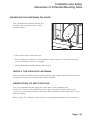
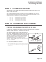
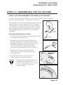
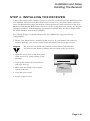
1
Residential
Customer Agreement
EFFECTIVE AS AND FROM SEPTEMBER 30, 2004 (“Agreement”)
Bell ExpressVu Inc., in its capacity as general partner of Bell ExpressVu L.P.
(“ExpressVu”) welcomes you as a Subscriber to its direct-to-home television and audio
broadcast programming. This Agreement contains the terms and conditions under which
ExpressVu is willing to grant its residential subscribers the right to receive and view the
broadcast of its direct-to-home (“DTH”) television and audio programming in Canada. If
you are receiving and viewing the broadcast of DTH television and audio programming
outside of your private residence, you are subject to the terms and conditions of the
commercial subscriber agreement, a copy of which is available at
www.bell.ca/satelliteagreements or by calling ExpressVu at 1 877 439-8502.
This version of the Agreement is effective as and from September 30, 2004 and replaces
and supersedes all previous versions of the ExpressVu Residential Customer Agreement.
Please visit our website at www.bell.ca/satelliteagreements or call us at 1 888 SKY-DISH
to obtain a copy of this Agreement that identifies all changes that have been made to it
from the immediate prior version. A large print version is also available on our website or
upon request. Une version française est disponible sur demande ou à
www.bell.ca/contratsatellite.
1. Introduction
Whenever we refer to “you” or the “Subscriber”, we are referring to you, as a subscriber
of ExpressVu’s Programming in Canada. By requesting, viewing or by paying for, any
Programming offered by ExpressVu, you will be deemed to have agreed to the terms and
conditions of this Agreement. If you do not agree with any of the terms and conditions
that are contained in this Agreement, you must immediately contact the ExpressVu
Customer Service Centre, as described below, to cancel your subscription.
2. Definitions
In this Agreement, the following terms have the following meaning:
“Customer Service Centre” means the ExpressVu Customer Service Centre, which may
be contacted by telephone at: 1 888 SKY-DISH (759-3474); by E-Mail to:
“[email protected]”; or mail to: “Customer Service, Bell ExpressVu LP, 100 Wynford
Drive, Toronto, Ont., M3C 4B4”;
“DTH Equipment” means the satellite equipment comprised of the IRD, satellite
antenna and remote control that you use to receive ExpressVu Programming;
“IRD” means the integrated receiver and decoder: this is the television set-top box which
decodes the video and audio programs as they come into your television from the dish
antenna;
“Programming” means, as the context requires, any or all of the ExpressVu
programming, subscription programs, programming packages, Pay Per View services,
interactive services, à la carte programs, any applicable fees and any other services that
we or our affiliates provide to you from time to time;
“Smart Card” means the conditional access card inserted or incorporated into the IRD.
The Smart Card is owned and used by ExpressVu to authorize reception of Programming;
“Statement” means the printed statement of your account that we send to you each
month, quarter or other billing period you choose that is offered by ExpressVu from time
to time; and
“ExpressVu” “we” “us” or “our” means Bell ExpressVu L.P., and where the context
requires, any successor company or entity, and their respective officers, directors,
employees or authorized agents.
Residential Customer Agreement
3. General information about our Terms and Conditions
The policies and practices reflected in this Agreement are used when providing you with
the Programming. ExpressVu reserves the right to change the terms and conditions of this
Agreement at any time. ExpressVu will notify you of any material change and the
effective date of that change so that you may cancel your subscription if you don’t agree.
The notice may be provided to you with your Statement, by separate written notice, by Email, or through ExpressVu's website at www.bell.ca/satelliteagreements. You should
visit our website periodically since the terms of this Agreement may change from time to
time. Notice may be in the form of providing you with an entirely new version of the
Agreement or by notifying you of the provisions that have been changed or added. If you
fail to cancel your subscription within seven (7) days of notice of a change to the
Agreement having been made available to you by ExpressVu, including, without
limitation, by way of posting an updated version of the Agreement on our website, you
will be deemed to have accepted such change. We reserve the right to change the
Programming that we offer, and our rates, charges or fees at any time. In the event of a
change in the contents of any Programming, you agree that we have no obligation to
replace or supplement the Programming previously offered that has been deleted,
rearranged or otherwise changed. You understand and agree that you will not be entitled
to any refund because of our change in the contents of any Programming. The provisions
of this Agreement will continue to apply to any issue related to this relationship after
termination of this Agreement.
4. Credit Card and Electronic Funds Transfer
All new and re-started Subscribers (i.e., Subscribers that have been disconnected and
desire to re-connect) of ExpressVu Programming are required to provide ExpressVu with
a valid major credit card or agree to pay for Programming through electronic funds
transfer (“EFT”) through a major financial institution in Canada as security for payment
of any outstanding amounts owed to ExpressVu. The credit card number that you provide
will be charged in the event you fail to pay your ExpressVu account when it is seventyfive (75) days past due. Your credit card number will not be provided to any other person
without your express prior consent. You hereby represent and warrant that the credit card
information you provide at the time of activation will be true, accurate and complete and
that the credit card number that you will or have provided is in your name, is valid and
has not expired. You agree that you will promptly advise ExpressVu of any change to
your EFT and/or credit card information or any change to, loss, theft or cancellation of,
your credit card and provide new EFT or credit card information if you open a new bank
account or obtain a new credit card, respectively. You hereby expressly, absolutely and
irrevocably authorize ExpressVu to charge your credit card or account through EFT for
any outstanding amounts owing for the Programming, or otherwise owed pursuant to the
terms of this Agreement, when and if seventy-five (75) days past due and this shall
constitute ExpressVu’s good and sufficient authority for so doing.
Residential Customer Agreement
5. About your use of the DTH Equipment
(a) The IRD Receiver/Decoder Unit
Your right to receive and view the Programming is granted only for IRDs situated in
Canada that have been authorized by ExpressVu to receive such Programming. Your IRD
will not operate without a Smart Card. ExpressVu reserves the right to verify that the
service address is located in Canada and that all active IRD’s on your account are located
at the address listed on your account as your “service address”. If any Subscriber is found
to be in violation of this or any other provision or policy, ExpressVu may disconnect
access to the Programming immediately without notice to such Subscriber. As a
Subscriber, you are responsible for all Programming that is ordered for your IRD. If you
have concerns about other persons ordering Programming for your IRD without your
authorization, request a personal identification number (PIN) for your account, which
will be used by our Customer Service Centre to help prevent unauthorized Programming
orders. You may also contact our Customer Service Centre to determine if any particular
IRD model is compatible with all Programming in which you are interested.
(b) Programming requires telephone connection
ExpressVu requires each IRD to be directly and continuously connected to the same
operating telephone line associated with your account. Any exception to this requirement
must be approved by ExpressVu prior to activation. Connection to an operating telephone
line is a condition of our granting you the right to receive and view the Programming and
we may, in our sole discretion, disconnect some or all Programming if we determine that
the IRD is not connected in this manner. We may verify the location of your IRDs
remotely or by contacting you directly. If ExpressVu is unable to contact you to perform
this verification, it may limit signal reception to a single receiver to a household
containing multiple receivers.
(c) Minimum level of Programming required
As a condition of our granting you the right to receive and view the Programming, you
are required to subscribe to and maintain a minimum level of Programming. If you are a
subscriber under a Term Contract, please review that document to determine the
minimum level of Programming required, otherwise, please contact 1-888-SKY-DISH for
all inquiries. In addition, unless your Term Contract states otherwise, the minimum
period of time that you must continue to subscribe to at least the minimum level of
Programming (and pay for it) is one (1) month. If you became or are an existing
Subscriber to ExpressVu’s Service before September 30, 2004, you must meet the
minimum spend requirements described in Section 6(f) below.
(d) Smart Cards
Smart Cards are non-transferable. Your Smart Card will work only in the IRD with which
it was packaged. Notwithstanding that the Smart Card was packaged with your IRD when
you purchased it, all Smart Cards remain our property and any tampering or other
unauthorized modification to a Smart Card may result in, and subject you to, legal action,
or any other action as set out in this Agreement. If you attempt to use that Smart Card
with any other IRD without our authorization, we may terminate your right to receive and
view the Programming. We may require that you return the Smart Card to us if it is
defective or damaged, prior to providing a replacement Smart Card to you. In addition,
we may require that you return the Smart Card to us if you terminate your account, and
failure to do so will result in a recovery charge being assessed against you.
Residential Customer Agreement
Lost/Stolen Cards:
If your Smart Card is lost or stolen we will replace your Smart Card for a charge of one
hundred dollars ($100.00) on your account.
Defective Smart Cards:
Defective Smart Cards will be replaced for a charge of one hundred dollars ($100.00) on
your account. You will receive a $100.00 credit to your account if (a) you return the
defective Smart Card to us within thirty (30) days, and (b) our investigation does not
reveal any unauthorized tampering of the Smart Card.
Damaged Smart Cards:
Damaged Smart Cards will be replaced for a charge of one hundred dollars ($100.00) on
your account. Upon our receipt of the damaged Smart Card thirty dollars ($30.00) will be
credited to your account – unless our investigation reveals unauthorized tampering.
(e) Liability for unauthorized use
If either of your IRD or Smart Card is destroyed, lost, stolen or otherwise removed from
your premises without your authorization, you must notify our Customer Service Centre
immediately in order to avoid liability for payment for any unauthorized use. You will not
be liable for unauthorized use after we have received your timely notification.
(f) Additional IRDs in the same household
It is a condition that any additional IRD/Smart Card combination(s) purchased and
activated to receive the same Programming as your initial IRD/Smart Card must be
located at the service address listed on your account and must be continuously connected
to the same operating telephone line. We may, in our sole discretion, disconnect the
Programming of any Subscriber that activated additional IRDs in breach of this section.
The activation of any new additional IRD(s)/Smart Card(s) is subject to the additional
IRD fee described in Section 6(g) below. You may activate up to a maximum of five (5)
additional IRDs on your account at any time. If you require more than five (5) additional
IRD(s), you must open a new separate account to activate such additional IRD(s) and you
will be billed separately for the services received through those additional IRD(s).
(g) Vacation Properties or Secondary Locations
No exceptions are made to section 5(a) for customers using the ExpressVu Service at a
secondary location, vacation property or mobile unit, such as a camper, boat or
recreational vehicle. Under no circumstances, including vacation properties, are
customers permitted to maintain multiple IRDs on one account that are active at different
locations simultaneously. If an IRD is installed in a mobile unit such as a camper, boat or
other recreational vehicle, you are only permitted to have one IRD active on that account.
6. Rates, Fees and Charges
(a) Introduction
Programming rates, fees and charges are charged in accordance with this Agreement.
ExpressVu reserves the right to impose other rates, fees and charges or to change the
amount of existing rates, fees and charges, at any time, but we will provide you with
notice of any such change. Our rates, fees and charges for Programming are available
upon request from the Customer Service Centre. If you have any concerns about our
rates, fees or charges, we would ask you to contact our Customer Service Centre.
You may also contact the governing body for broadcasters in Canada, the CRTC, by
writing to it (with a copy to ExpressVu) at the following address:
CRTC, Ottawa, Ontario, K1A 0N2.
Residential Customer Agreement
(b) Billing policies, Statements and payments
You agree to pay, in full, all amounts billed for Programming and to pay all taxes, fees
and other charges, if any, which are now or may in the future, be assessed on the
Statement for Programming and any other services you receive from us. We will bill you
each month in advance for your Programming. (Usage based Programming will be billed
in arrears.) The Statements you receive will show the total amount due, together with
other changes since your last Statement, such as applied payments, credits, purchases and
other charges to your account. It will also show any other fees assessed. Unless otherwise
stated in the Statement, the total amount due is payable upon receipt. If there are billing
errors or other requests for credit, you should contact our Customer Service Centre. You
must contact us within forty-five (45) days of the date you receive the Statement which
contained the error, in order to avoid service disruptions. Undisputed portions of the
Statement must be paid before the next Statement is issued to avoid an administrative fee
for late payment. Additional copies of your Statement can be requested from the
Customer Service Centre, subject to payment of the appropriate additional Statement fee.
(c) Paying your bill late, or with insufficient funds
You agree to pay us in full by the payment due date for the Programming and for any
other fees or charges due to us. Payment of your bill after the due date, will result in us
charging you interest on all overdue amounts up to the greater of: a) a compounded
interest rate of two per cent (2%) per month (26.82% per year); or b) the highest interest
rate permissible by law, at ExpressVu's discretion, until paid in full. If your account
remains unpaid for a period of sixty (60) days, we may also charge you an administration
fee, to offset the additional processing costs associated with delinquent accounts. The
administration fee is currently twenty-five dollars ($25.00). Other fees and charges may
also be assessed. For example, cheques which are dishonoured or returned for insufficient
funds, or a refused bank account/credit card preauthorized debit, will be subject to an
“NSF Fee”, currently twenty-five dollars ($25.00) per occurrence. If partial payments are
made, they will be applied first to the oldest outstanding bill. If you send cheques or
money orders marked “payment in full,” we can accept them without waiving any of our
rights to collect any other amounts owed by you, notwithstanding your characterization
of the payment. You understand and agree that in the case of late payment or nonpayment
for any Programming ordered by you or for any of the charges stated below, we may
report such late payment or nonpayment to credit reporting agencies.
(d) Termination of Programming by ExpressVu
If you do not pay in full all amounts owing as shown on your Statement within thirty (30)
days after the date when payment is required, or if you fail to comply with any of your
obligations under this Agreement at any time, we have the right to disconnect your
Programming, in our sole discretion, and without notice or demand to you. We also
reserve the right, without notice or demand, to take whatever steps are necessary to
disable or modify the software in your IRD if you breach any of your obligations under
this Agreement, including, without limitation, receiving Programming that you have not
paid for, in whole or in part. When we disconnect your Programming, we have the right
to charge you a deactivation fee, which is currently fifty dollars ($50.00). If we are
required to use a collection agency or lawyer to collect money that you owe us or to
assert any other right that we may have against you, you agree to pay the reasonable costs
of collection or other action. These costs may include, but are not limited to, the costs of
a collection agency, reasonable legal fees and court costs. We will require you to pay all
past due charges, and the deactivation fee, and any costs which are reasonably incurred
Residential Customer Agreement
by ExpressVu as a result of the collection efforts on outstanding amounts, before we
reconnect your Programming.
(e) Authorization to check credit history
ExpressVu hereby provides you with notice that by subscribing to the Programming, you
authorize us to make inquiries into your credit history at any time in our sole discretion,
and to record the results of those credit inquiries on your account file at ExpressVu.
(f) Minimum Spend Requirement
If you became or are an existing Subscriber to ExpressVu’s Service before September 30,
2004, who currently spends more than twenty-two dollars ($22.00) per month and who
wishes to downgrade), you must, in addition to the requirement to subscribe to one of the
“Locals” or the “Réseaux francophones” packages, either spend at least twenty-two
dollars ($22.00) a month on Programming, excluding any Pay Per View services,
interactive services and all account administration fees, or subscribe to a minimum of two
“Theme Packs”.
(g) Additional IRD Fee
Subscribers who activate more than one IRD on an account, or who subsequently activate
an additional IRD on their account, may be charged an account administration fee by
ExpressVu, which is currently set at $4.99 per month, for the activation and continued
use of multiple IRD(s)/Smart Card(s) on their account. This fee may be reduced or
eliminated by ExpressVu for Subscribers who subscribe to specific combo
programming packages.
(h) Reconnection Fee
ExpressVu charges an account administration fee, currently thirty-five dollars ($35.00),
to re-activate an IRD which had been permanently deactivated upon request of the
Subscriber, or where the Subscriber transfers or assigns ownership of the IRD or
otherwise transfers or assigns responsibility for payment of an existing account with the
consent of ExpressVu.
(i) System charge
A system charge, currently set at $2.99 per month, shall apply to all Subscribers. This fee
may be reduced or eliminated by ExpressVu for Subscribers who subscribe to specific
combo programming packages.
7. Your termination, or suspension, of Programming
(a)) If you want to terminate all or a portion of your Programming
(i) Downgrading your Programming: You have the right to terminate or downgrade the
reception of any part of your Programming for any reason at any time by notifying our
Customer Service Centre, provided that: (x) any continuing Programming is subject to
the minimum Programming requirements set out in Section 5(c) above; and (y) your
account must be in good standing with all payments up to date. You are responsible for
ensuring that these two conditions are satisfied. ExpressVu will deactivate the
Programming you request to be terminated effective as of the next billing cycle date after
receiving your notice. Since you would have paid for the Programming you are
terminating or downgrading in advance up to the next billing cycle date, no credit or
refund will be payable in respect of such terminated or downgraded Programming. In
addition, no deactivation fee will be payable in such case. However, if you are a Term
Contract Subscriber and you call to downgrade your Programming below the minimum
Residential Customer Agreement
Programming commitment you agreed to, certain fees or charges may be applicable
pursuant to the Term Contract you entered into. Please refer to your Term Contract to
determine the applicable fees or charges, if any.
(ii) Terminating or cancelling your Programming: You have the right to terminate the
reception of all of your Programming for any reason at any time by notifying our
Customer Service Centre. ExpressVu will deactivate all the Programming you receive on
the thirtieth day after receiving your notice to cancel. However, if you are a Term
Contract Subscriber, and you call to deactivate all of your Programming, certain fees or
charges may be applicable pursuant to the Term Contract you entered into. Please refer
to your Term Contract to determine the applicable fees or charges, if any. If you are
entitled to a credit for any amount in excess of ten dollars ($10.00), ExpressVu will send
you a cheque for that refund amount upon customer request, but we will not offer any
refund for an amount of less than ten dollars ($10.00).
(iii) If you cancel your right to receive and view any Programming, you are still
responsible for payment of all outstanding balances accrued up to the date of termination.
(b) If you want to temporarily suspend your Programming
You may temporarily suspend your right to receive and view the Programming at any
time simply by contacting the Customer Service Centre, provided that your Programming
is suspended for a minimum period of six (6) weeks, and not greater than six (6) months.
ExpressVu charges an account administration fee, currently $9.99, for this service. Upon
reactivation, the minimum one (1) month service requirement set out in Section 5(c) will
apply. If you fail to call and reactivate your account at the end of the permitted six (6)
month period, your account will automatically be reactivated, billing will be resumed and
you will receive the Programming you were receiving prior to its suspension. If you have
temporarily suspended your Programming and decide during that time to terminate or
downgrade your Programming pursuant to Section 7(a) (i) or (ii) above, as applicable,
your account will automatically be reactivated prior to any such requested change taking
effect so that the terms and conditions of Section 7(a) (i) or (ii), as applicable, shall apply
to your request to terminate or downgrade your Programming.
(c) Your transfer of account or equipment
You may not assign or transfer your rights to the Programming without our written
consent. If you do, we may deactivate your Programming. You agree to notify us
immediately, but in any event not more than five (5) days, after you move, sell, give
away or otherwise transfer any part or all of your DTH Equipment to anyone else. You
are considered to be the registered owner of your DTH Equipment and beneficiary of the
rights in the Programming until we receive such notice, and you may be liable for any
charges or fees incurred by the use of your DTH Equipment by anyone else up to the time
that we receive your notice. To transfer your DTH Equipment to another person or
account, an administration transfer fee of thirty-five ($35.00) will be applied to the
account of the new owner.
8. Furnishing of Programming by ExpressVu
(a) Exclusion of Liability
EXPRESSVU, AND/OR ANY OF ITS SUPPLIERS (INCLUDING, WITHOUT
LIMITATION, TELESAT CANADA) WILL NOT BE LIABLE FOR ANY
INTERRUPTIONS IN PROGRAMMING OR LIABLE FOR ANY DELAY OR
FAILURE TO PERFORM, IF SUCH DELAY OR NONPERFORMANCE ARISES IN
CONNECTION WITH ANY ACTS OF GOD, FIRES, EARTHQUAKES, FLOODS,
POWER FAILURE, SATELLITE FAILURE OR MALFUNCTION, FAILURE TO
Residential Customer Agreement
REPLACE EXISTING TECHNOLOGY, ACTS OF ANY GOVERNMENTAL BODY
OR ANY OTHER CAUSE BEYOND OUR REASONABLE CONTROL. WE MAKE
NO WARRANTY, EITHER EXPRESSED OR IMPLIED, REGARDING THE
PROGRAMMING PROVIDED TO YOU. ALL SUCH WARRANTIES ARE
EXPRESSLY EXCLUDED. IN NO EVENT SHALL WE HAVE ANY LIABILITY FOR
SPECIAL, INDIRECT, INCIDENTAL OR CONSEQUENTIAL DAMAGES
RELATING TO THE DTH EQUIPMENT OR RESULTING FROM OUR
FURNISHING OR FAILURE TO FURNISH ANY PROGRAMMING TO YOU OR
FROM ANY FAULT, FAILURE, DEFICIENCY OR DEFECT IN PROGRAMMING
FURNISHED TO YOU. IN NO EVENT SHALL EXPRESSVU’S LIABILITY TO THE
SUBSCRIBER EXCEED THE TOTAL VALUE PAID TO EXPRESSVU BY THE
SUBSCRIBER FOR PROGRAMMING. It is your responsibility to impose any
restrictions on viewing by you, other members of your household, or your or their
invitees, and we shall have no liability to anyone due to, or based on, the content of any
of the Programming furnished to you.
(b) Acknowledgement re: DTH Equipment
YOU ACKNOWLEDGE AND AGREE THAT: (i) YOUR DTH EQUIPMENT HAS
BEEN ACQUIRED SEPARATELY AND APART FROM THIS AGREEMENT FOR
THE PROVISION OF PROGRAMMING. YOU ALSO ACKNOWLEDGE THAT
EXPRESSVU IS NOT THE MANUFACTURER, DISTRIBUTOR, INSTALLER OR
RETAILER OF YOUR DTH EQUIPMENT, AND THEREFORE HAS NO LIABILITY
WHATSOEVER FOR SUCH EQUIPMENT, INCLUDING, WITHOUT LIMITATION,
IN THE EVENT THAT THE SOFTWARE IN YOUR IRD BECOMES DISABLED OR
MODIFIED DUE TO THE IRCUMSTANCES OUTLINED IN SECTION 8(b)(ii) OR
UPDATED OR UPGRADED AS OUTLINED IN SECTION 8(b)(iii). ANY RIGHTS
AND REMEDIES WITH RESPECT TO THE DTH EQUIPMENT MUST BE
HANDLED DIRECTLY WITH THE MANUFACTURER, INSTALLER OR SUPPLIER
OF SUCH EQUIPMENT.
(ii) YOUR IRD CONTAINS SOFTWARE THAT IS UNDER LICENSE TO, OR
OWNED BY, EXPRESSVU. YOUR LICENSE TO USE THIS SOFTWARE IS
LIMITED TO RECEIVING AND VIEWING PROGRAMMING AUTHORIZED BY
EXPRESSVU ONLY AND FOR NO OTHER PURPOSE. IF EXPRESSVU HAS
REASONABLE GROUNDS TO BELIEVE THAT YOU ARE RECEIVING
UNAUTHORIZED PROGRAMMING, IN WHOLE OR IN PART, OR USING THE
SOFTWARE FOR ANY OTHER UNAUTHORIZED PURPOSE, EXPRESSVU
RESERVES THE RIGHT TO MODIFY OR DISABLE THE SOFTWARE IN YOUR
IRD. WARNING: IF THE SOFTWARE IN YOUR IRD IS DISABLED OR MODIFIED,
YOUR RECEIVER MAY NOT FUNCTION PROPERLY. YOU MAY NOT MODIFY,
TEST, REVERSE ENGINEER, DECOMPILE, TAMPER OR ACCESS THIS
SOFTWARE FOR ANY REASON WHATSOEVER.
(iii) EXPRESSVU RESERVES THE RIGHT, FROM TIME TO TIME, TO UPDATE OR
UPGRADE THE SOFTWARE IN YOUR IRD TO ENSURE THAT IT AND YOUR
DTH EQUIPMENT WILL REMAIN COMPATIBLE WITH AND FUNCTION
PROPERLY WITH ANY TECHNOLOGICAL ADVANCES OR IMPROVEMENTS
MADE TO OUR DTH SERVICE. IN CERTAIN CIRCUMSTANCES, IT MAY BE
NECESSARY TO MODIFY OR REMOVE SOME SOFTWARE FEATURES TO
INTRODUCE NEW FEATURES AND TO ENSURE YOUR IRD REMAINS
COMPATIBLE WITH SUCH TECHNOLOGICAL ADVANCES OR
Residential Customer Agreement
IMPROVEMENTS.
(c) Programming availability
All Programming is provided on a subject to availability basis. Certain Programming
transmitted by us, including but not limited to sports events, may be “blacked out” in
your area of reception from time to time at the request of the programmer for copyright
or other reasons. If you circumvent or attempt to circumvent any of these blackouts, you
may be subject to legal action. Programming may also be subject to temporary
interruption due to natural phenomena such as thunderstorms. ExpressVu will not refund
charges for the blackout period or temporary interruptions. In addition, EXPRESSVU
WILL NOT BE LIABLE FOR ANY LOSS OR DAMAGE WHICH YOU SUFFER AS A
RESULT OF ANY SUCH BLACKOUT OR TEMPORARY INTERRUPTION. However,
if ExpressVu causes a material interruption of Programming which is not related to
natural phenomena or causes outside of its control, ExpressVu will provide a credit or
refund, at the request of the Subscriber, for the Programming interruption period. For
greater certainty, no credit or refund will be provided for Programming interruptions
resulting from ExpressVu disabling or modifying the software in an IRD pursuant to
Section 8(b) (ii) of this Agreement, or if ExpressVu can no longer provide any particular
Programming for any reason.
(d) Private viewing
The right we provide you to receive and view the Programming is for your private home
viewing, use and enjoyment. You agree that the Programming provided will not be
received or viewed outside of your private residence. You are only permitted to exhibit
the Programming solely in your private residence and not in any other areas. The
Programming may not be rebroadcast, transmitted or performed in any form, and no
admission charged, or any other consideration received, by or for the benefit of
Subscriber from any third party in return for allowing such third party to listen to or view
any Programming provided by us.
(e) Warning against piracy
It is against the law to receive the Programming, or any portion of the Programming,
without paying for it (unless permitted to do so by ExpressVu). Doing so may result in
civil or criminal penalty. ExpressVu also reserves the right to take any other action to
prevent the reception of its Programming without payment to, or authorization by,
ExpressVu, including, without limitation, the right to modify or disable the software in
the IRD in accordance with Section 8(b)(ii) of this Agreement.
(f) Privacy of Personal Information
Your personal information will be protected by ExpressVu in a manner consistent with
the Bell Customer Privacy Policy and the Bell Code of Fair Information Practices. As a
Subscriber, you have given your consent implicitly to the use of your personal
information, as described in the above policy and practices. You may withdraw your
consent at any time by contacting the Customer Service Centre or by using the opt-out
form at the bottom of the following website: www.bell.ca/privacypolicy.
(g) Additional Rules for Pay Per View (PPV) Programming
Unless otherwise indicated by ExpressVu at the time you place your order for PPV
Programming, all sales of PPV Programming are final. In the event that ExpressVu is
unable to provide any PPV Programming that you have ordered, ExpressVu shall credit
you the amount for that PPV Programming. ExpressVu shall have no other liability for
cancelled events or failure to provide any PPV Programming. Certain PPV Programming
Residential Customer Agreement
may only be ordered if you also subscribe to other prerequisite Programming. You agree
to indemnify and hold harmless ExpressVu from any claims, liabilities, losses or damages
resulting from your use of PPV Programming in contravention of Section 8(d) or 8(e) of
this Agreement.
9. Arbitration
You agree that any claim or dispute (whether originating in contract or tort, or pursuant to
any applicable statutes, regulations or common law principles and whether past, present
or future) that arises out of or is related to: (a) the terms and conditions of this
Agreement; (b) any oral or written statements; or (c) any promotions or advertisements
related to this Agreement (collectively the “Claim”), will be referred to and decided upon
by a sole arbitrator in an expedited and simplified arbitration proceeding. You and we
will make every reasonable effort to agree on the appointment of the arbitrator within
fifteen (15) days of the commencement of the arbitration proceeding, failing which, the
arbitrator will be appointed by the court in the province in which you reside. The
arbitrator shall have the right to require either party to pay all costs and expenses of the
arbitration, including the arbitrator’s fees and expenses.
10. Miscellaneous Provisions
(a) Applicable law
This Agreement, including all matters relating to its validity, construction, performance
and enforcement, shall be governed by applicable federal law, and the laws and
regulations of the province where Programming is provided. These terms and conditions
are subject to amendment, modification or termination if required by such laws or
regulations. If any provision in this Agreement is declared to be illegal or in conflict with
any such law or regulation, that provision may be deleted or modified, without affecting
the validity of the other provisions.
(b) Change of name, address or telephone number
You agree to give us prompt notice of your change of name, mailing address, residency,
address, telephone number or credit card number. You may do this by notifying our
Customer Service Centre. Notices are deemed to have been received when they arrive at
our Customer Service Centre.
(c) Enforceability
You and we agree that each provision of this Agreement shall be construed as separable
and divisible from every other provision and that the enforceability of any one provision,
or portion thereof, shall not limit the enforceability, in whole or in part, of any other
provision hereof.
© Copyright 2004 Bell ExpressVu L.P. “ExpressVu™”
is a registered trade-mark of Bell ExpressVu LP. Bell
ExpressVu L.P.
Bell ExpressVu L.P.
100 Wynford Drive, Toronto, Ontario M3C 4B4
ATTENTION
YOUR RECEIVER CONTAINS SOFTWARE THAT IS UNDER LICENSE TO OR
OWNED BY BELL EXPRESSVU.
YOUR LICENSE TO USE THIS SOFTWARE IS LIMITED TO RECEIVING AND
VIEWING PROGRAMMING AUTHORIZED BY BELL EXPRESSVU ONLY.
IF BELL EXPRESSVU HAS REASONABLE GROUNDS TO BELIEVE THAT YOU
ARE RECEIVING UNAUTHORIZED PROGRAMMING OR USING THE
SOFTWARE FOR ANY OTHER UNAUTHORIZED PURPOSE, IT RESERVES THE
RIGHT TO MODIFY OR DISABLE THE SOFTWARE IN YOUR RECEIVER.
WARNING: IF THE SOFTWARE IS DISABLED OR MODIFIED, YOUR
RECEIVER MAY NOT FUNCTION PROPERLY.
YOU MAY NOT MODIFY, TEST, REVERSE ENGINEER, DECOMPILE, TAMPER
OR ACCESS THIS SOFTWARE FOR ANY REASON WHATSOEVER.
RECEIVING SIGNALS WITHOUT AUTHORIZATION, INCLUDING FOR THE
PURPOSE OF “TESTING”, IS THEFT AND MAY RESULT IN CRIMINAL
CHARGES OR A CIVIL SUIT BEING BROUGHT AGAINST YOU.
INSTALLATION GUIDE
Table of Contents
Safety Instructions ............................................................................ I-i
Installation and Setup............................................................................... I-1
Introduction ......................................................................... I-1
Components of the Satellite Antenna ..................................... I-2
Summary of Installation ........................................................ I-4
Before You Start Installation ................................................. I-5
Discussion of Potential Mounting Sites .................................. I-9
Some Key Points to Consider ................................................ I-9
Finding the Right Location for the Dish ................................. I-18
Multi-Satellite Antenna Installation ....................................... I-21
System Set-up ................................................................... I-26
51 cm Dish Setup Guide ...................................................... I-27
3.1A Pre-assemble the Parts ................................................ I-27
3.1B Attaching the Mount to your Dwelling ............................ I-28
3.1C Installing the Dish on the Mount ................................... I-29
3.1D Connecting Things Together ......................................... I-29
60 cm Dish Setup Guide ..................................................... I-30
3.2A Pre-assemble the Parts ............................................... I-30
3.2B Attaching the Mount to your Dwelling ............................ I-31
3.2C Installing the Dish on the Mount ................................... I-32
3.3D Connecting Things Together ........................................ I-32
90 cm Dish Setup Guide............................................................ I-33
3.3A Pre-assemble the Parts ............................................... I-33
3.3B Attaching the Mount to your Dwelling............................ I-34
3.3C Installing the Dish on the Mount ................................... I-36
3.3D Connecting Things Together ........................................ I-36
120 cm Dish Setup Guide .................................................... I-37
3.4A Pre-assemble the Parts ............................................... I-37
3.4B Attaching the Mount to your Dwelling ........................... I-38
3.4C Installing the Dish on the Mount ................................... I-39
3.4D Connecting Things Together ........................................ I-39
Installing the Receiver ......................................................... I-41
Ground and Wire the Satellite Antenna................................. I-42
Aligning the Dish ................................................................ I-44
Change languages ............................................................. I-48
Help .................................................................................. I-49
Satellite Location Table ...................................................... I-50
Vertical Elevation Protractor ................................................ I-53
Connect Receiver to Telephone Connection .......................... I-54
How to Test the System ...................................................... I-54
Order Your Bell ExpressVu Programming .............................. I-57
Pre-Authorized Payment Plan .............................................. I-58
Program the Remote .......................................................... I-60
Security Features................................................................ I-61
Wire Your System Together ................................................. I-63
Wiring Setup Diagram ......................................................... I-67
Safety
Instructions
You should always follow these instructions to help ensure against
injury to yourself and damage to your equipment.
• Read all safety and operating instructions before you operate the receiver.
• Retain all safety and operating instructions for future reference.
• Heed all warnings on the receiver and in the safety and operating instructions.
• Follow all installation, operating, and use instructions.
• Unplug the receiver from the AC power outlet before cleaning. Use only a damp cloth
for cleaning the exterior of the receiver.
• Do not use accessories or attachments not recommended by the manufacturer, as they
may cause hazards and will void the warranty.
• Do not operate the receiver in high-humidity areas, or expose it to water or moisture.
• Do not place the receiver on an unstable cart, stand, tripod, bracket, or table.
The receiver may fall, causing serious personal injury and damage to the receiver.
• Do not block or cover slots and openings in the receiver. These are provided for
ventilation and protection from overheating. Never place the receiver near or over a
radiator or heat register. Do not place the receiver in an enclosure such as a cabinet
without proper ventilation.
• Do not stack the receiver on top of or below other electronic devices.
• Operate the receiver using only the type of power source indicated on the marking
label. Unplug the receiver power cord by gripping the power plug, not the cord.
• Insert the plug properly. The receiver is equipped with a polarized AC line plug (one
blade is wider than the other). This plug will fit into the power outlet only one way.
This is a safety feature. If you are unable to insert the plug fully into the outlet, try
reversing the plug. If the plug still fails to fit, contact an electrician to replace the
obsolete outlet. Do not defeat the safety purpose of the polarized plug.
• Route power supply cords so that they are not likely to be walked on or pinched by
items placed upon or against them. Pay particular attention to cords at plugs,
convenience receptacles, and the point where they exit from the unit.
• Do not overload wall outlets or extension cords, as this can result in a risk of fire or
electrical shock. Never insert objects of any kind into the receiver through openings,
as the objects may touch dangerous voltage points or short out parts. This could cause
fire or electrical shock.
Page I-i
Installation Guide
• We recommend that the outdoor components of the antenna system be grounded in
accordance with local, provincial, and national codes.
• We strongly recommend using an outlet that contains surge suppression or ground fault
protection. For added protection during a lightning storm, or when the receiver is left
unattended and unused for long periods of time, unplug it from the wall outlet and
disconnect the lines between the receiver and the antenna. This will prevent damage
caused by lightning or power line surges.
• Do not locate the antenna near overhead power lines or other electric light or power
circuits, or where it can fall into such power lines or circuits. When installing the
antenna, take extreme care to avoid touching such power lines or circuits, as contact
with them can be fatal.
• Do not attempt to service the receiver yourself, as opening or removing covers (except
for the Smart Card access door on the receiver front panel) may expose you to
dangerous voltage, and will void the warranty. Refer all servicing to authorized
service personnel.
• Unplug the receiver from the wall outlet and refer servicing to authorized service
personnel whenever the following occurs:
❒
❒
❒
❒
❒
The power supply cord or plug is damaged;
Liquid has been spilled, or objects have fallen into the receiver;
The receiver has been exposed to rain or water;
The receiver has been dropped or the chassis has been damaged;
The receiver exhibits a distinct change in performance.
• When replacement parts are required, ensure that the service technician uses
replacement parts specified by the manufacturer. Unauthorized substitutions may
damage the receiver or cause electrical shock or fire, and will void the warranty.
• Upon completion of any service or repair to the receiver, ask the service technician to
perform safety checks to ensure that the receiver is in proper operating condition.
Page I-ii
Installation
and Setup -A 5 Step Process
INTRODUCTION
Congratulations on your selection of a Bell ExpressVu system. We thank you for your
purchase. We are confident that you will be pleased with the performance, capabilities,
entertainment options, and ease of operation of your Bell ExpressVu system for many
years to come.
Your Bell ExpressVu system complies with MPEG II and DVB standards for
compressing audio and video data. How does this benefit you? It means the Bell
ExpressVu system will be compatible with new technologies in consumer electronic
products as they arrive on the market, including digital video disk (DVD) players, digital
video cassette recorders (VCRs), and data communication networks.
The Bell ExpressVu Customer Service Call Center provides a single source for you to get
answers to all your questions. For all your questions or comments, call us at 1-888-SKYDISH (1-888-759-3474), or visit our Web Site at www.expressvu.com.
If you do not want to install your system yourself, you can have it installed by a
professional. Ask your retailer for information about the installer in your area. (You will
be given a toll-free number. Call the toll-free number and leave a message. The installer
will call you back to set an appointment).
If you do intend to install your Bell ExpressVu system yourself, this chapter provides
installation procedures. The procedures are relatively simple, but do require some skill in
construction-related tasks. Be sure to follow all warnings and cautions; they are provided
for your safety.
An optional Installation Kit is available. This Kit includes typical hardware used during
installation, and a more detailed Installation Kit Guide. Contact your Bell ExpressVu
dealer.
It is important that you follow all local building codes and the electrical
codes specified by your local electric company, as well as standard safety
procedures for installing and working with this type of equipment.
Improper procedures or installation can result in damage to the equipment
or the building, and harm to you. If you are not sure about whether your
installation follows these codes, contact a licensed building inspector or
electrician in your area for assistance.
Take extreme care to avoid contacting any overhead power lines, lights, and
power circuits while you are installing the satellite antenna. Contact with
any of these could prove fatal. Do not install the satellite antenna near
power lines.
See "Safety Instructions" on page I-i for additional safety information.
Page I-1
Installation Guide
COMPONENTS OF THE SATELLITE ANTENNA
Note: The following pictures are not to scale.
The fully assembled Bell ExpressVu satellite antenna looks like this.
See "Install the Satellite Antenna" on page I-13 for the procedure to
assemble and install the satellite antenna. Following are descriptions of
each component of the satellite antenna.
DBS LNBF (Low Noise Block amplifier with integrated Feed)
DBS LNBF - Single Output
If you purchased the single-output LNBF to use with one
Bell ExpressVu receiver, your package contains this LNBF.
DBS LNBF - Dual Output
If you purchased the dual output LNBF for use with more
than one Bell ExpressVu receiver, your package contains
this LNBF.
LNBF Support Arm
The LNBF support arm attaches the LNBF and the dish to
the mast assembly. The support arm may come in two pieces
for larger antennas.
Dish
The dish collects and focuses the satellite signal onto the LNBF.
Note: The dish may have either three or four bolt holes.
Flathead bolts with nuts attach the dish to the support arm.
LNBF Screws
The LNBF screw attaches the LNBF to the support arm.
Cable Clip (optional)
The cable clip holds the cable to the top of the support arm.
Page I-2
Installation and Setup
Components of the Satellite Antenna
Mounting Brackets and Mast Assembly
The mounting bracket and mast assembly attaches the
dish and LNBF assembly to the mounting surface.
If you are planning to use a pole to mount the satellite
antenna, you will not need the mounting bracket and
mast assembly. However, we recommend you keep
them in case you decide to move the satellite antenna.
Optional Installation Kit
The Installation Kit is an optional product that contains the hardware and materials that
you would typically use during various types of installation. To buy the Installation Kit,
contact the location where your Bell ExpressVu system was purchased or call the
Customer Service Call Center at 1-888-SKY-DISH (1-800-759-3474).
The Installation Kit contains the following:
•
•
•
•
•
•
•
•
•
•
•
•
Dual telephone adapter
Dual grounding block
9.1-meter Grounding wire, either 8 gauge aluminum or 10 gauge copper
7.6-meter RG-6 (coaxial) cable with "F" connectors
30-meter RG-6 (coaxial) cable with "F" connectors
4 concrete anchors (3 1/8" x 1 7/8")
2 Lag bolts (3" x 5/16")
4 Cable ties
4 Lag bolts (2" x 5/16")
Compass
Silicone sealant
10 Cable clips for the coaxial cable
If you did not purchase the Installation Kit, but still plan to install your Bell ExpressVu
system yourself, we recommend that you gather the appropriate materials before
beginning installation. Note: Amount of RG-6 (coaxial) cable required will depend on
distance between LNBF and receiver.
The tools you will need to complete the installation will vary, depending on the type of
installation that you do. If you find that you do not have the tools and skills for a certain
procedure, call a professional, such as an Bell ExpressVu dealer or an electrician, for
assistance. These tools are not included in the Installation Kit.
Page I-3
Installation Guide
SUMMARY OF INSTALLATION
Following is a summary of the procedures to install and set up your Bell ExpressVu
system. We recommend that you perform the procedures in the order presented.
1. Unpack the satellite antenna, receiver, and parts (see page I-6)
and the optional installation kit, if you purchased one (see page I-3).
2. Review "What You Need to Know" (see page I-6).
3. Connect the receiver to your TV set, and make sure the Smart Card is installed
(see page I-8).
4. Determine the approximate location of the Bell ExpressVu satellite
(see page I-18).
5. Find the best location on your property for the satellite antenna, with a clear line
of sight to the satellite (see pages I-18 through I-20).
6. Assemble the satellite antenna and attach it to a solid surface (see pages I-27
through I-40).
7. Ground the satellite antenna, and wire it to the Bell ExpressVu receiver
(see pages I-42).
8. Aim the satellite antenna for the strongest possible signal (see pages I-44
through I-48).
9. Connect the receiver to an active telephone connection (see page I-54). With the
receiver wired to the TV and the antenna properly installed, you will be able to see
the Bell ExpressVu Program Guide, which tells you about available programs,
channels, and services.
10.Order your programming by calling the Bell ExpressVu Customer Service Call Centre
at 1-888-SKY-DISH (see page I-57).
11. Review “Bell ExpressVu Pre-Authorized Payment Plan”. (see page I-58).
12.Program the remote control to control the receiver and your other electronic
equipment. This feature is not available on all receiver models. (see page I-60).
13.Wire the receiver to your audio system, VCR, DVD and other electronic equipment,
as required (see page I-63).
Page I-4
Installation and Setup
Before You Start Installation
STEP 1: BEFORE YOU START INSTALLATION
This is a typical
"Mount"shown
attached to a wall.
Notice that the top
portion is "Plumb".
THE KEY
} Top
TO SETTING UP YOUR
SYSTEM EASILY
– THIS
IS
IMPORTANT
The key to setting up the system is in the accurate initial setting of the vertical elevation
of the dish. The vertical elevation is the amount of tilt upwards, from horizontal, toward
the sky, which is required to “see” the satellite. This is best achieved by mounting the
dish support mast so that the top portion, to which the dish clamps attach, is as “Plumb”
as possible. That is to say: the top portion of the mount should be as perpendicular to the
earth as you can manage - this is true for wall mounting, roof mounting, any kind of
mounting. If it is “Plumb“, then, when the dish is mounted on it and the dish is tilted
upward toward the satellite at the correct vertical elevation angle, the dish can be easily
panned (East/West movements) to find the satellite.
UNPACK AND CHECK CONTENTS
As you unpack the system, confirm that all the parts are included. See "Package
Contents" on page I-6 for a list of the included components.
Note: Keep the shipping materials in which these items are packed, in case you ever
need to return them.
Unpack the contents carefully. Electronic equipment can be easily damaged if bumped or
handled roughly. Examine all parts for damage that may have occurred during shipment.
If you find any damage, immediately call the location where your Bell ExpressVu system
was purchased, or the Bell ExpressVu Customer Service Call Centre at
1-888-SKY-DISH, before continuing with installation.
The size of your dish will vary depending on the part of Canada in which you live. The
standard diameter of a Bell ExpressVu dish is 51 cm, however, 60 cm, 90 cm or 1.2m
dishes are also available. If you require the large dish, we recommend that you hire a
professional to install it because installation of the 90 cm and 1.2 m dishes is a more
exacting project.
Page I-5
Installation Guide
PACKAGE CONTENTS
• User and Installation Guide
• Bell ExpressVu satellite antenna assembly
• Bell ExpressVu receiver
• Accessories
❒
❒
❒
❒
❒
7.6-metre RJ11 telephone cable
2.4-metre phono (RCA) 3-connector cable
1.8-metre modulator cable
2.4-metre S-VIDEO cable (optional to install) Model 4700 only.
Remote control, with four (4) AAA batteries packaged separately
In addition, we provide an optional Installation Kit, which includes the necessary
hardware and cables that you would typically use during installation. Contact the
location where your Bell ExpressVu system was purchased for more information, or call
the Bell ExpressVu Customer Service Call Centre at 1-888-SKY-DISH for the location of
a licensed dealer near you.
WHAT YOU NEED TO KNOW
Because you will make modifications to the location where you mount the satellite
antenna, we suggest that you be familiar with and be able to safely perform the following
procedures.
• You should be able to use a plumb line or level to set both horizontal and vertical
surfaces. This is especially critical for vertical surfaces.
• You should know how to drill holes in the mounting surface (whether wood, brick,
cinder block, etc.).
• You should know how to drill holes and run cabling through your building. This
includes sealing the holes once the cable has been installed.
WHAT YOU NEED TO HAVE
If you did not purchase the installation kit, you will need the following materials:
• Coaxial cables and connectors (RG6 recommended up to 100ft. For longer distances
consult an installer)
• Fastening devices to attach the mount to your dwelling
• Waterproofing for the outdoor connections
• Grounding materials
• Cable ties
Page I-6
Installation and Setup
Before You Start Installation
You will also need some tools:
A 7/16”,1/2”, 9/16” wrench (varies with dish size)
A Phillips screwdriver
A spirit level
A drill and drill bits (masonry and wood)
A 3/8” masonry drill bit for the concrete anchors
INSTALL BATTERIES IN THE REMOTE
The remote is shipped with four AAA batteries, packaged separately.
1. Press down on the slot in the battery case cover
(on the back of the remote) to open the cover.
2. If you are replacing old batteries, remove all
four batteries.
3. Insert the new batteries, being sure to match the
plus (“+”) ends with the plus indicators on the
remote. The batteries alternate plus and minus
(“-”) ends when properly seated.
4. Replace the cover by inserting the tabs into the
slots, and snapping the cover into place.
If the remote does not work after installing the batteries, confirm that the batteries are
properly seated, with the plus and minus ends aligned correctly.
SET THE REMOTE ADDRESS
When you get your receiver and remote, they are set to address 1. Unless you experience
problems, you do not need to change the address at this time. If you want to change the
address, see “Set the Remote Address” on page I-60.
You may need to set the remote address in any of the following situations:
• You have a UHF remote, and you encounter interference caused by other nearby UHF
remotes (for example, a neighbour's UHF remote or a UHF remote being used in
another room of your building).
• There is another Bell ExpressVu receiver and remote being used in the vicinity.
Note: In either of the above situations, you may need to assign an address to your
remote and receiver, so that the receiver responds only to that remote.
Page I-7
Installation Guide
• If your receiver and remote addresses do not match, you must match them to be able to
use the remote. See "Set the Remote Address" on page 3-9.
TEMPORARILY CONNECT THE RECEIVER TO TV
You must connect the receiver to your TV and make sure the Smart Card is installed to
get the information to aim your satellite antenna. At this time, it is not necessary to fully
wire your receiver to all your electronic equipment.
See "Wiring Setups" in your User Manual for suggested wiring configurations.
INSTALL THE SMART CARD
Most systems come with the ExpressVu Smart Card
already installed in the receiver. If your Smart Card
came in a separate package, you need to install it
into the Smart Card slot in the receiver.
The receiver will work only with the
Smart Card installed. You must use
the Smart Card that was supplied with
your receiver.
1.
Open the access door on the front panel of the
receiver by gently pulling on the left edge.
2.
Unwrap the Smart Card, and insert it face up
(face up is logo up).
3.
Make sure the Smart Card is firmly seated in the slot.
4.
Close the access door.
Page I-8
Installation and Setup
Discussion of Potential Mounting Sites
DISCUSSION OF POTENTIAL MOUNTING SITES
When you are surveying your property for appropriate sites for the satellite antenna, keep
in mind that you can mount the satellite antenna on a variety of surfaces: brick, cinder
block, wood, some sidings, rooftop, or a pole.
Because installing the satellite antenna may involve drilling into the wall or roof of your
building, or digging a hole and using cement, you should be confident of the location
before beginning installation. Errors can be expensive and time-consuming.
The following guidelines apply to all mounting surfaces and locations.
WEATHER AND WIND CONSIDERATIONS
The satellite antenna has been built to withstand most kinds of weather. However,
extremely strong winds could damage the base on which the satellite antenna is mounted.
A strong wind can cause the satellite antenna to exert several hundred kilograms of
pressure on the mounting surface, so the surface must be stable and strong. Such a
mounting surface also helps ensure against movement of the satellite antenna, which
would interfere with signal reception. In general, the stronger the signal you maintain,
the better your chance of uninterrupted reception during periods of snow, rain, and heavy
cloud cover.
SOME KEY POINTS TO CONSIDER
DO’S
You should always follow these instructions to help ensure against injury to
yourself and damage to your equipment or building. See "Safety
Instructions" on page I-i for further safety instructions.
• Assemble the satellite antenna in a safe location before climbing up to the mounting
location. Use caution when climbing, and when working at the mounting location.
Depending on the mounting location and size of your dish, 2 people may be required
to install the mount and antenna to your dwelling.
• Install the satellite antenna only on a solid surface such as cinderblock, brick, or solid
foundation material. If you install it on the side of a building, be sure to attach the
bolts directly to a building stud or other solid material. Use the appropriate drilling
and attachment hardware for the surface.
• Make sure you have determined the best location for the satellite antenna before
drilling the holes in your building or setting up the mounting pole.
Mistakes can be costly.
• All installations should conform to your local building and electrical codes. If you are
not sure, contact a licensed building inspector or electrician in your area to assist you.
Be aware that community covenants, if any, may have additional requirements.
Page I-9
Installation Guide
• If possible choose a site that is accessible in most weather conditions. You may
need to clean snow, ice or debris off the satellite antenna.
• Place the satellite antenna as close to the receiver as possible. We recommend using
no more than 30 meters of RG-6 (coaxial) cable between the receiver and the satellite
antenna, unless you install a line amplifier to boost the signal.
• Consider seasonal changes. The site may appear unobstructed in the winter, but spring
and summer foliage could block the signal to the satellite antenna.
DO NOTS
• Never install the satellite antenna under power lines.
• Do not install the satellite antenna where it can be jostled, bumped, or blocked by
people, animals, or vehicles.
• Do not install the satellite antenna where it is exposed to high winds.
• Do not try to install the satellite antenna in windy or stormy weather, particularly if
there is a chance of lightning.
• Do not attempt to fasten the satellite antenna to the mortar between bricks or cinder
blocks.
• Do not mount the satellite antenna on vinyl or aluminum siding. These materials are
structurally too weak to securely hold the satellite antenna, even with a building stud
underneath.
• Do not install the satellite antenna on stucco or imitation masonry unless the base
material is solid. Do not mount the satellite antenna on composite materials such as
strand, chip, fiber, or particle board unless the fastener attaches securely to a wall stud,
rafter, or other foundation material beneath the surface.
• Do not mount the satellite antenna in a tree.
Page I-10
Installation and Setup
Discussion of Potential Mounting Sites
MOUNTING THE ANTENNA ON BRICK
We define "brick" as a solid brick wall
or other structure. This does not include
brick facing that is used on some
buildings over the main structure. If you
are mounting the satellite antenna on
brick facing, see "Mounting the Antenna
on Siding," below.
You can mount the satellite antenna on a
solid brick wall.
• The brick surface must be flat and even.
• The mortar between the bricks should be in good to excellent condition. The satellite
antenna foot should be mounted on several bricks. As the wind tugs on the satellite
antenna, the foot will put heavy pressure (several hundred kilograms) on those bricks
in different directions. Loose or weakened mortar may allow the bricks to shift,
changing the dish angle and reception quality, and possibly damaging the satellite
antenna and the building. The installed satellite antenna could also hasten the
deterioration of old mortar.
• To mount the satellite antenna on brick, be sure that all of the fasteners are set into the
brick, not into the mortar between the bricks. Use materials necessary to follow the
local building codes.
MOUNTING THE ANTENNA ON SIDING
We do not recommend mounting the satellite antenna on aluminum or vinyl siding.
These materials can be structurally unsound, causing eventual shifting of the dish. To
mount the satellite antenna on solid siding, be sure to follow the suggestions below.
• The surface must be flat and even. You may need to use a separator, or shim, between
the shingles to even the siding surface.
• Mount the foot on the foundation material beneath the siding surface. This may be a
building stud, cinder block, or other solid material. To locate the studs, find the
vertical line of nails where the siding is attached to the building, or use a stud finder.
Page I-11
Installation Guide
MOUNTING THE ANTENNA ON CINDER BLOCK
You can mount the satellite antenna on cinder
blocks, whether they are part of a wall or the side
of a building.
• The surface must be flat and even.
• Be sure that the cinder block and mortar are in good condition.
• We recommend using toggle anchors and machine bolts, inserted into the hollow of the
block, as fasteners. Other types of anchors may not have the required strength.
MOUNTING THE ANTENNA ON THE ROOF
You can mount the satellite antenna on the roof.
This usually provides the highest available
location.
• Attach the satellite antenna to a rafter beneath the roof surface. You can locate the
rafter by looking for the nails attaching the fascia board to the rafters. You can also
locate the rafters from inside the attic.
• To prevent the roof from leaking, you should caulk the holes, or use silicone sealant
around the holes and at the bottom of the satellite antenna foot where it contacts the
surface. Apply the sealant before you bolt the foot down tight.
Page I-12
Installation and Setup
Discussion of Potential Mounting Sites
MOUNTING THE ANTENNA ON WOOD
You can mount the satellite antenna on a
wooden deck, wooden beam, or other
wooden surface.
• The surface must be flat and even.
• Be sure that the wood has a solid foundation, and is secured. It should be a strong
piece that cannot be moved or jiggled.
• Do not mount the satellite antenna on a railing.
INSTALL THE SATELLITE ANTENNA
Once you have found the direction and elevation of the satellite and decided on the best
mounting location, you can install the satellite antenna.
ORIENTATION OF MAST OR POLE
It is very important that the upper part of the mast or the mounting pole,
whichever is used, be truly plumb (vertical). If not, the elevation provided by the
receiver for your location will be inaccurate. This will make it more difficult for you to
find the satellite.
Refer to page I-4, “Summary of Installation” to begin the installation of your antenna.
Page I-13
Installation Guide
Vertical Mounting
Surfaces with Mast
The figure above
shows how you
should attach the
mast to the foot for
mounting on vertical
surfaces.
Horizontal Mounting
Surfaces with Mast
Pole Mounting
Surfaces
The figure above
shows how you
should attach the
mast to the foot for
mounting on
horizontal surfaces.
The figure above
shows how you
should attach the
dish support and
bracket to a
mounting pole.
Install the Antenna Mount
Before you install the antenna mount, you should make sure that you can
route the cable from the mounting location into your building, drilling holes
where necessary, to the receiver.
Assemble the satellite antenna in a safe location before climbing up to the
mounting location. Use caution when climbing, and when working at the
mounting location.
1. Gather all the items you will need for the assembly.
2. If the dish support arm and the bracket that holds it came
separately, attach the arm to the bracket with the
supplied bolts.
3. Mount the foot on the solid surface you have chosen.
4. Adjust the mast so that when the foot is mounted, the
upper part of the mast is, as close to vertical as possible.
Use a plumb line or bubble level to measure the upper
part of the mast. Alignment of the dish is more difficult
if the mast is not plumb.
Page I-14
Installation and Setup
Discussion of Potential Mounting Sites
You may have either one or two LNBF cables to attach,
depending on which type of LNBF you purchased and how
many receivers are being installed.
Note: If you have to attach two cables to the LNBF,
the following instructions apply to both cables. Use
only RG-6 coaxial cables with "F" connectors. Do
not use the 1.8-meter RF or VHF cable supplied with
the receiver. This cable is used for the receiver to
TV connection.
5. Place the dish on the support arm. Align the
flathead bolts with the dish support bolt holes
on the dish supports.
6. Insert each flathead bolt into one of the holes, and
secure it by threading a lock nut onto the bolt on
the back side. Do this for all the flathead bolts.
7. Tighten the bolts so that they are snug.
This is a picture of the support arm and bracket
with the dish attached.
8. Tilt the support bracket to the approximate elevation
of the satellite. Use the elevation you found earlier
on the Satellite Location Reference Chart.
46CM
60
10
If you have the bracket with points above the
elevation washer, align the elevation marks on the
bracket with the points on the washer.
90
20
30
40
50
60
70
80
If you have the bracket where the edge of the mast
shows through the curved slot, align the edge with
the desired elevation mark.
9. Slide the mast clamp onto the mast.
Tighten the elevation bolts and the pivot bolt so that
the bracket is snug, but can still be moved up and down.
10.Turn the antenna mount on the mast or pole to align
the LNBF support arm in the direction of the satellite.
Use the direction you found earlier in the Satellite
Location Reference Chart.
Page I-15
Installation Guide
Tighten the mast clamp bolts so that the clamp is snug,
but can still be moved back and forth.
11. Thread the LNBF cable into the cable hole near
the mast foot, up the mast and out the top of the mast.
Do not kink or pinch the cable.
12. Take the end of the cable coming out the top of the
mast, and thread it up the mast sleeve of the support arm.
13. Loop the end of the cable over the pivot bolt.
14. Bring the cable back down on the outside of the
mast sleeve, between the dish supports.
15. Thread the cable through the arm and out the end of the arm.
16. Slip the weather boot(s) onto the LNBF cable(s).
To do this, insert the end of the cable with the screw
connector into the smaller end of the boot and work
it through. When you are finished the boot should slide
freely over the cable but hold snugly when slipped up
over the screw connector. Be patient. This is a difficult
and somewhat painstaking job. (If possible, place
weather boot on cable before putting on "F" connector).
17. Attach the LNBF to the LNBF cable(s). Slide the
weather boot up securely to cover the cable/LNBF
connection at the base of the LNBF.
18. Fit the LNBF onto the end of the dish support arm, sliding
it until it is inserted firmly. Attach LNBF to the support arm
using the LNBF screw and washer.
INSTALLING A METAL POLE MOUNT
You can mount the satellite antenna on a metal pole if
necessary. This allows you a wider range of locations for
installation.
Note: If used, the metal pole should have an outside diameter
of approximately 1 5/8 inches (approx. 4 cm), and should be
sturdy enough not to flex in high winds. If the clamp ends up
being slightly loose, use weather proof sandpaper or emery
cloth to shim the clamp, and tighten.
Page I-16
Installation and Setup
Discussion of Potential Mounting Sites
• You can mount the satellite antenna on a metal pole that is attached to an existing
building. Using this method, you can raise the satellite antenna to gain a line-of-sight
view of the satellite if you cannot find a better location. Be sure to follow all safety
requirements, and properly ground the satellite antenna and pole.
• You can also mount the satellite antenna on a metal pole installed in the ground, as
long as the soil provides a firm foundation and the pole does not allow the antenna to
move during windy weather.
Be sure to locate and avoid underground sewer, gas, water, and telephone
lines before digging. Your local utility companies can tell you where these
are located.
Before you attach the pole to its mounting surface or install the pole in the
ground, you should make sure that you can route the cable from the
mounting location into the building, drilling holes where necessary, to the
receiver. If the pole is installed in the ground, be sure that you can route the
cable overhead or underground in a conduit or with a direct burial cable.
1. The most common method to install the pole in the ground is to
use cement to secure it in a hole. Be sure that the pole remains
at 90˚ from horizontal as the cement dries. You may want to use
guy wires or braces to keep the pole steady. The bottom of the hole
should be 15 centimeters below the frost line in areas where
temperatures fall below freezing. In most areas of Canada, a
1-meter-deep hole for the pole should be sufficient.
2. A way of ensuring that the pole does not rotate in the dried
cement is to cut the bottom of the pole at an angle, and to place
a brick or flat rock in the bottom of the hole to support the pole
before pouring in the cement.
3. Use a plumb line to ensure that the pole is at 90˚ from horizontal. Take at least two
measurements on different sides of the pole periodically while the cement is drying.
Having the pole plumb allows you to accurately aim the antenna. If the pole is slightly
off plumb, you can still aim the antenna for good reception, but it is very difficult.
4. Typically, the cable is routed down outside the pole. However, if you want to feed the
LNBF cable up through the pole in the same manner as you would through the mast,
you will need to drill a hole in the pole big enough to do this. The hole should be
above ground after the pole has been set in the cement.
You will not need the metal foot and mast assembly provided with the antenna for this
installation, but we recommend you keep the assembly in case you wish to relocate the
antenna later.
5. Follow the instructions for mounting the satellite antenna mast, but use the metal pole
in place of the mast and foot.
6. Bring the LNBF cable down the outside of the pole. Be sure to secure the cable firmly,
but not too tightly, to the pole using tie-downs.
Page I-17
Installation Guide
STEP 2:
FIND THE RIGHT LOCATION FOR THE DISH
The Dish must be at a location on your dwelling which gives a clear, year-round,
unobstructed “view” of the satellite and which is also free from occasional blockages due
to vehicles or passers-by.
Locating the appropriate site for your Bell ExpressVu dish is a two step process: First,
use your compass and the satellite direction data provided in this guide, to estimate the
general direction of the satellite. Use this information to find the right spot to mount the
dish on your dwelling. Next, get more serious about the installation; confirm that your
dish has a clear unobstructed “view” of the satellite and that the dish can be mounted
securely.
WHAT YOU WILL NEED
•
•
•
•
•
Compass
Level
Satellite Receiver connected to a television
Satellite Location Table (page I-50)
Vertical Elevation Protractor (page I-53)
DETERMINE DIRECTION TO THE SATELLITE
You must determine the direction the Bell ExpressVu satellite from your location to help
you determine where to mount your antenna. You must have a clear line of sight from the
antenna location to the satellite. Use the following procedure to find the best location for
the antenna, while keeping in mind the considerations referenced in DISCUSSION OF
POTENTIAL SITES on page I-9.
After you finish mounting the antenna, you will need to re-aim the dish to get the strongest
signal. Please see STEP 5: ALIGNING THE DISH on page I-44 for this procedure.
Page I-18
Installation and Setup
Find The Right Location For The Dish
WHERE IS IT?
The Bell ExpressVu satellite orbits the Earth over the equator. For everyone in Canada,
this means that the satellite will be south of your location.
The Bell ExpressVu satellite is approximately 35,680 kilometers above the surface of the
Earth. It is in what is called a "geosynchronous orbit." This means that the satellite
stays aligned over one place on the surface of the Earth. If you could see the satellite, it
would seem to hang in one spot in the sky.
Because the satellite does not move in relation to the surface of the Earth, it is easy to
maintain the signal. Once your antenna is aimed at the Bell ExpressVu satellite, the
antenna will not have to move to follow the satellite.
When determining the approximate location of the satellite, you will need to find the
azimuth (South, Southeast, or Southwest direction to the satellite) and elevation (angle up
to the satellite) from your location. "Azimuth" is also called "direction." (As shown on a
compass). We use the term "direction" in this guide.
Refer to "Satellite Location Reference Chart" on page I-50. Find your city or a city
near you and note down the appropriate settings for direction and elevation.
FIND A CLEAR LINE OF SIGHT
"Find a clear line of sight" means to find a location for the satellite antenna so that its
view of the orbiting satellite is unobstructed by trees, buildings, or any other obstructions.
This includes making sure that sapling trees are
not likely to grow up or out into the line of sight.
The Homemade Sextant
Also, consider seasonal changes. An unobstructed C a r d b o a r d t r i a n g l e co p i e d
f r o m b a ck co ve r
site in winter may be obstructed by foliage in
spring and summer.
Cardboard Cutout
If you need a way to determine if you have a clear
“view” to the satellite, try this procedure: Cut out a
cardboard triangle with its base about 8-10 inches
long. Make the angle of the triangle equal to the
vertical elevation angle for your location as given
in the Table (page I-50) or simply use the triangle
as illustrated on page I-53 as a template. Tape it to
your level as shown in the sketch. Now you have a
homemade sextant! Next, look up the edge of the
cardboard while holding the level horizontal while
aiming it at the correct compass heading. If there is
an obstruction, locate the dish elsewhere.
L e ve l
Using
the Sextant
Page I-19
Installation Guide
1. Take a compass and the direction and elevation numbers
to your planned location for the satellite antenna.
(VERY IMPORTANT)
Make sure the compass is well away from metal objects, and
that there are no magnetic or electronic devices nearby.
Holding the compass so the needle can swing freely, turn the
compass until the dark end of the compass needle is aligned
on the N. This points to magnetic North. The compass face
is divided into 360 degrees, North is zero degrees (0˚), East
is 90˚, South is 180˚, and West is 270˚.
2. On the compass, find the direction number provided by the
Satellite Location Reference Chart. Turn to face this
number, while keeping the dark end of the needle over the
N. This is the direction of the satellite. Find a landmark,
or lay a stick or board on the ground lined up in that
direction.
3. Use the elevation number from the chart to find out
how high the satellite is in the sky from your location.
You know that vertical is 90˚, and horizontal 0˚, and
halfway in between is 45˚.
Stand close to where you plan to mount the satellite
antenna and face in the direction that you marked for
the direction to the satellite. Using the elevation angle,
find the closest approximation to that angle in the sky.
You now are pointing to the approximate location of
the satellite.
4. Note whether there are any obstructions between you and
the satellite. Leave a margin for adjustment, because
you have not yet aimed the antenna exactly.
If there are obstructions, you will have to find a new
location, or remove the obstruction, if possible.
5. If necessary, repeat steps 1 through 4 until you
have located the best location for the antenna.
The best location should provide a sturdy support
for the antenna, plus it must have a clear line of
sight. Mark the spot and the direction to the satellite.
Page I-20
Installation and Setup
Multi-Satellite Antenna Installation
MULTI-SATELLITE ANTENNA INSTALLATION
The procedures in this guide are specifically for the Bell ExpressVu's Multi-Satellite
Antenna installation. For more detailed information, you may need to refer to your
satellite system’s Installation Instructions/User Manual
1. Before you start, read all safety precautions in your satellite system’s Installation
Instructions/User Manual.
2. Use the Satellite Location "Look" Angles Chart located at the back of this manual for
specific coordinates to point the satellite dish in your area. The azimuth, elevation and
skew define the exact direction to aim your dish so that it can receive signals from the
satellite. Azimuth is the compass direction; elevation is the "up-down" angle; and
skew is the ‘side-to-side’ rotation angle of the satellite dish.
3. Using the azimuth and elevation angles from Step 2, find a location for the satellite
dish. With a compass, find the required azimuth angle. Then, use the elevation angle
to find out how high the satellites are in the sky from your location. Make sure
nothing blocks the line of sight to the satellites. For more detailed instructions on how
to find the satellites, refer to your satellite system’s Installation Instructions/User
Manual.
4. Mount the mast to a solid surface so that the dish antenna cannot move or be bumped
out of adjustment. Keep in mind that physical and environmental conditions can affect
your satellite dish’s ability to receive a clear satellite signal. The conditions to be
aware of are: eaves and overhangs on your building or house, wind, plant growth, and
deterioration of the mounting surface. Never mount to a tree.
5. Align the top part of the mast so that it is absolutely vertical. If the top part of the mast
is off vertical by only a few degrees, it will be difficult or impossible for you to find
the satellites. Take at least two readings with a bubble level, on sides of the mast that
are 90 degrees apart from one another (see diagram).
Page I-21
Installation Guide
6. Assemble the satellite dish, following the diagram. Your satellite system’s Installation
Instructions/User Manual contains detailed assembly instructions.
7. Loosen both skew bolts and set the skew by rotating the dish mounting bracket to
align the red mark with the required angle on the skew scale. Tighten the skew bolts
securely to keep the dish from rotating. Once the skew is set, do not try to fine-tune
this angle when aiming the dish.
8. Set the elevation by tilting the dish mounting bracket to align the red edge with the
required angle on the elevation scale. Tighten the elevation bolts, but do not tighten
the pivot bolt at this time.
Page I-22
Installation and Setup
Multi-Satellite Antenna Installation
9. Note the Y-bracket is labeled ‘82˚’ on one side and ‘91˚’ on the other. Only use the
RG-6 coaxial cable for all connections between the LNBFs and receiver. Label one
coaxial cable '91' on both ends and the other coaxial cable '82' on both ends. If you are
installing two receivers,repeat this step for the additional two cables. You will then
have two cables labeled ’91’ and two labeled ’82’. This will help reduce confusion
later.
10.Thread the labeled coaxial cables through the support arm and the Y-bracket. Make
sure the cable(s)labeled ’91’ are threaded through the ’91’ side and the ’82’ cable(s)
are threaded through the ’82’ side as shown. Attach to Y-bracket using the Y-bracket
screw. Connect the cable(s) to each LNBF. Attach one LNBF to the Y-bracket in slot
labeled '91' using the two LNBF screws. Repeat for '82' LNBF.
11.Slide the dish assembly down onto the mast. Make sure the pivot bolt rests on top of
the mast. Turn the dish assembly so that it points in the general direction of the
satellite using the azimuth angle from step two.
12.Ground the coaxial cable(s) by following the wiring diagram outlined in your satellite
system’s Installation Instructions/User Manual. Ensure that the grounding conforms
with your area’s local electrical code.
13.Connect the coaxial cable from the '91' LNBF directly to the satellite receiver. You
may use a female-to-female connectore to do this (optional). Connect the receiver to
the television using the composite (RCA-type) video and audio outputs.
14.Turn ON the televisionand receiver. Adjust video input setting on television until the
'Point Dish and Signal Strength' menu is displayed.
Page I-23
Installation Guide
15.Turn the dish assembly back and forth very slowly, until the signal strength bar turns
green to indicate the signal. Ensure that your body is not blocking the path between
the dish and the satellite! Note: If you cannot find the signal, turn the dish assembly
back to the original azimuth setting. Loosen the elevation bolts and increase the
elevation angle by two degrees. Tighten the elevation bolts and try turning the dish
assembly slowly back and forth. Repeat these steps, raising and lowering the
elevation, until you find the satellite signal.
16.Once you have the signal, turn the dish assembly back and forth very slightly until the
signal strength bar displays the maximum possible signal strength. Tighten the mast
clamp blots. Then, loosen the elevation bolts and adjust the elevation of the dish up
and down slightly until the signal strength bar displays a maximum signal. Do not
adjust the skew setting! Tighten all the bolts in the dish assembly so that the dish
cannot be moved.
17.Once you have the strongest possible signal, press the Cancel button on the remote
control to exit the ‘Point Dish and Signal Strength’ menu. The receiver will then
display an ‘Attention’ message on the television screen asking whether the installation
is complete. Use the remote control arrow buttons to highlight the Yes option, and
press the Select button. The receiver will automatically ‘download’ the latest operating
software. Once complete, the receiver will display a ‘Warning’ message stating that
you are tuned to a channel that has not been subscribed to.
Page I-24
Installation and Setup
Multi-Satellite Antenna Installation
18.Connect the cables labeled '82'
leading from the satellite dish
to each 'Dish 1' input on both
SW21 multi-dish switches.
Next, connect the cables
labeled '91' leading from the
satellite dish to each 'Dish 2'
91
input on both SW21 multi-dish
switches Finally, take cable
from the other side of the
82
multi-dish switch and connect
directly to each Bell Express
91
82
Vu satellite receiver. If you
possess only one satellite
receiver, use either multi-dish
switch output to connect the
cable in order to relay the satellite signal. Whichever multi-dish switch that is left unused will be available in case you wish to connect a second satellite receiver in future.
19.Complete installation and wiring by following the instructions in this manual.
20.After the wiring is done, complete the satellite system installation by following the
'System Set-up' instructions outlined on page I-26.
Page I-25
Installation Guide
SYSTEM SET-UP
COMPLETING INSTALLATION WITH MULTI-SATELLITE
‘POINT DISH’ ONSCREEN MENUS:
1. Once the satellite system installation is finished,
power on the satellite receiver and display the
‘Point Dish’ screen on the TV. Note that the
display has now changed to show satellite
reception from both satellite locations: Bell
ExpressVu 91˚ and Bell ExpressVu 82˚. (If the
‘Point Dish’ screen has not changed, power off
the satellite receiver so it can begin to download
the new Multi-Satellite software. Ensure the
receiver is set to accept upgrades via the
‘System Setup’ menu.)
2. Using the remote, confirm signal strength by
selecting one satellite and then the other.
3. Next, perform a test on the satellite system
switches by selecting ‘Check Switch’ option on
the screen. On the following display, select
‘Check’ to begin the automatic set-up for
systems installation.
4. Once the test is completed, an ‘Installation
Summary’ screen will appear and indicate the
various settings for each switch output and also
verify proper satellite reception.
Congratulations! The installation for your new
Bell ExpressVu Multi-Satellite system is now
complete! Simply call 1 888 SKY DISH (7593474) to activate your satellite receiver(s) and
begin enjoying Bell ExpressVu’s 100% digital quality television.
www.bell.ca/satellite
1-888-SKY-DISH
Bell is a trade-mark of Bell Canada used under license;
ExpressVu is a trade-mark of Bell ExpressVu L.P. All Rights Reserved.
Page I-26
Installation and Setup
Assembling The Dish
STEP 3: ASSEMBLING THE DISH
The following section outlines the assembly procedure for all four dish sizes: 51 cm,
60 cm, 90 cm, and 120 cm.
The overall assembly procedure is similar for all sizes, but there are some specific
differences which are addressed in four separate sections. Please refer to the section
which is relevant to the dish size you have purchased:
•
•
•
•
Step 3.1
Step 3.2
Step 3.3
Step 3.4
Assembling the 51 cm Dish
Assembling the 60 cm Dish
Assembling the 90 cm Dish
Assembling the 120 cm Dish
STEP 3.1: ASSEMBLING THE 51 CM DISH
STEP 3.1A: PRE-ASSEMBLE THE PARTS (51 CM DISH)
It’s best to pre-assemble the dish indoors, so that it is all ready to place on the mast
outdoors, quickly and easily ... especially if it’s cold out.
The complete system consists of three main parts: the
dish mount, the dish assembly, and the receiver. The
mount consists of the foot (base plate) and a bent pipe
called the mast. These two parts are pre-assembled.
The dish assembly consists of the antenna, or dish,
the dish support bracket, the (LNBF) low noise
amplifier, and the LNBF support arm. The receiver is
also fully assembled.
Dish
LNBF Arm
Mount
Mast
Pre-assemble the Dish as follows:
1. Bolt the dish to the support bracket and the support
arm; there are clear instructions and pictures in the
antenna box.
Page I-27
Installation Guide
2. Determine your specific vertical elevation from
the Table (page I-50) and adjust the angular tilt of
the antenna so that the edge of the red mark on the
gauge is set to your vertical elevation. In our
diagram here, it is set for 38.5 degrees.
3. Lightly tighten the bolt on the gauge side of the
angular pivot; leave the bolt on the back side
slightly loose.
4. Your antenna assembly is now ready to be placed
on the outdoor mount assembly.
Ve r t i c a l El e v a t i o n
Gauge
The mount for attaching the dish to the dwelling is made of steel and, as a
result, it is very magnetic. If you are too close, it can adversely alter your
compass readings.
STEP 3.1B: ATTACHING THE MOUNT TO YOUR DWELLING
(51 CM DISH)
The mount should be attached to your dwelling before putting the dish assembly on it.
When fastening it to your wall or roof, etc., make sure that the top portion is “plumb”;
you can get it right by using a spirit level on both the front and side of the top piece. It is
important to affix the mount firmly to your structure with at least 4 fasteners so that the
wind will not alter the direction of the dish.
Note: Plumb means vertical in all directions. A flagpole is plumb.
WALL MOUNT
HORIZONTAL MOUNT
ROOF MOUNT
Here is how it can be done:
SIDE VIEW
1. Place the mount foot on the surface location
where you intend to attach it to the structure.
2. Arrange the holes in the foot to be over solid
material and adjust the top part of the mast to
be approximately plumb.
3. Put your spirit level on the side of the pipe (see
diagram) and move the foot slightly to make the
pipe vertical. Don’t worry about getting
the pipe level in the front and back direction this will be done with the pivot arrangements
after the foot is mounted.
Page I-28
PRESS LEVEL
AGAINST MOUNT
FRONT VIEW
Installation and Setup
Assembling the 51cm Dish
4. Mark the location of one of the holes and remove the mount.
5. Drill the hole and attach the mount foot with the one fastener only.
6. Now, once again, position the top of the mast to be approximately plumb; then place a
level on the side of the pipe and pivot the mount foot slightly around the one
attachment and adjust the mount foot to make the pipe vertical. Once achieved, drill
the other 3 holes while the mount foot is still properly in place. (Alternatively, you can
mark the holes, remove the mount, then drill).
7. Attach the mount with the 4 fasteners; seal the holes with silicone to prevent water
damage to your dwelling.
8. Place your level on the front face of the top section of the mast and adjust the pipe to
be vertically level by pivoting around the base bracket. Tighten down the nuts on the
bracket when it is level. There are no further adjustments to make on the mount.
9. Check your work... The top of the mast should now be “plumb”!
If you have trouble fastening the mount to a surface, try mounting a solid
piece of wood to your dwelling’s surface first, then fastening the mount to
the wood.
STEP 3.1C: INSTALLING THE DISH ON THE MOUNT
(51 CM DISH)
You have installed the mount on your dwelling and you have pre-assembled the antenna
unit, ready to be installed on the mount.
There are just a few steps here:
1. Slide the antenna assembly over the mast.
2. Lightly tighten the two nuts on the back of the mast clamp, so that the antenna can
pivot in the East/West directions but not be loose.
3. You are ready to carry out the antenna alignments, as soon as the wiring in Step 3.1D
is completed.
STEP 3.1D: CONNECTING THINGS TOGETHER (51 CM DISH)
The wiring is accomplished as follows:
1. Thread a length of coaxial cable through the dish as shown in diagram
2. Slip the weather boot(s) onto the LNBF cable(s). To do this, insert the end of the cable
with the screw connector into the smaller end of the boot and work it through. When
you are finished the boot should slide freely over the cable but hold snugly when
slipped up over the the screw connector. Be patient. This is a difficult and somewhat
painstaking job. (If possible, place weather boot on cable before putting on “F”
connector).
Page I-29
Installation Guide
3. Attach the LNBF to the LNBF cable(s).
Slide the weather boot up securely to cover the
cable/LNBF connection at the base of the LNBF.
4. Slip the LNBF onto the end of the arm, until
contact is made with the LNBF bracket stops
and put in screw through arm and LNBF.
5. Route and fasten the cable in a neat, unobtrusive
manner in such a way so it cannot be damaged by
accident. Connect the opposite end of the cable to
your receiver, to the connector marked
“Satellite In”.
6. See page I-42 for instructions concerning safety grounding.
The assembly and mounting of the 51 cm Dish is complete.
Proceed to page I-41 Installing the Receiver.
STEP 3.2: ASSEMBLING THE 60 CM DISH
STEP 3.2A: PRE-ASSEMBLE THE PARTS (60 CM DISH)
It’s best to pre-assemble the dish indoors, so that it is all ready to place on the mast
outdoors, quickly and easily ... especially if it’s cold out.
The complete system consists of three main parts: the
dish mount, the dish assembly, and the receiver. The
mount consists of the foot (base plate) and a bent pipe
called the mast. These two parts are pre-assembled.
The dish assembly consists of the antenna, or dish,
the dish support bracket, the (LNBF) low noise
amplifier, and the LNBF support arm. The receiver is
also fully assembled.
Pre-assemble the Dish as follows:
1. Bolt the dish to the support bracket and the support
arm; there are clear instructions and pictures in the
antenna box.
Page I-30
Dish
LNBF Arm
Mount
Mast
Installation and Setup
Assembling the 60cm Dish
2. Determine your specific vertical elevation from
the Table (page I-50) and adjust the angular tilt of
the antenna so that the edge of the red mark on the
gauge is set to your vertical elevation. In our
diagram here, it is set for 38.5 degrees.
3. Lightly tighten the bolt on the gauge side of the
angular pivot; leave the bolt on the back side
slightly loose.
4. Your antenna assembly is now ready to be placed
on the outdoor mount assembly.
Ve r t i c a l El e v a t i o n
Gauge
The mount for attaching the dish to the dwelling is made of steel and, as a
result, it is very magnetic. If you are too close, it can adversely alter your
compass readings.
STEP 3.2B: ATTACHING THE MOUNT TO YOUR DWELLING
(60 CM DISH)
The mount should be attached to your dwelling before putting the dish assembly on it.
When fastening it to your wall or roof, etc., make sure that the top portion is “plumb”;
you can get it right by using a spirit level on both the front and side of the top piece. It is
important to affix the mount firmly to your structure with at least 4 fasteners so that the
wind will not alter the direction of the dish.
Note: Plumb means vertical in all directions. A flagpole is plumb.
WALL MOUNT
HORIZONTAL MOUNT
ROOF MOUNT
Here is how it can be done:
SIDE VIEW
FRONT VIEW
1. Place the mount foot on the surface location
where you intend to attach it to the structure.
2. Arrange the holes in the foot to be over solid
material and adjust the top part of the mast to
be approximately plumb.
3. Put your spirit level on the side of the pipe (see
diagram) and move the foot slightly to make the
pipe vertical. Don’t worry about getting
the pipe level in the front and back direction this will be done with the pivot arrangements
after the foot is mounted.
PRESS LEVEL
AGAINST MOUNT
Page I-31
Installation Guide
4. Mark the location of one of the holes and remove the mount.
5. Drill the hole and attach the mount foot with the one fastener only.
6. Now, once again, position the top of the mast to be approximately plumb; then place a
level on the side of the pipe and pivot the mount foot slightly around the one
attachment and adjust the mount foot to make the pipe vertical. Once achieved, drill
the other 3 holes while the mount foot is still properly in place. (Alternatively, you can
mark the holes, remove the mount, then drill).
7. Attach the mount with the 4 fasteners; seal the holes with silicone to prevent water
damage to your dwelling.
8. Place your level on the front face of the top section of the mast and adjust the pipe to
be vertically level by pivoting around the base bracket. Tighten down the nuts on the
bracket when it is level. There are no further adjustments to make on the mount.
9. Check your work... The top of the mast should now be “plumb”!
If you have trouble fastening the mount to a surface, try mounting a solid
piece of wood to your dwelling’s surface first, then fastening the mount to
the wood.
STEP 3.2C: INSTALLING THE DISH ON THE MOUNT
(60 CM DISH)
You have installed the mount on your dwelling and you have pre-assembled the antenna
unit, ready to be installed on the mount.
There are just a few steps here:
1. Slide the antenna assembly over the mast.
2. Lightly tighten the two nuts on the back of the mast clamp, so that the antenna can
pivot in the East/West directions but not be loose.
3. You are ready to carry out the antenna alignments, as soon as the wiring in Step 3.2D
is completed.
STEP 3.2D: CONNECTING THINGS TOGETHER (60 CM DISH)
The wiring is accomplished as follows:
1. Thread a length of coaxial cable through the dish as shown in diagram
2. Slip the weather boot(s) onto the LNBF cable(s). To do this, insert the end of the cable
with the screw connector into the smaller end of the boot and work it through. When
you are finished the boot should slide freely over the cable but hold snugly when
slipped up over the the screw connector. Be patient. This is a difficult and somewhat
painstaking job. (If possible, place weather boot on cable before putting on “F”
connector).
Page I-32
Installation and Setup
Assembling the 90cm Dish
3. Attach the LNBF to the LNBF cable(s).
Slide the weather boot up securely to cover the
cable/LNBF connection at the base of the LNBF.
4. Slip the LNBF onto the end of the arm, until
contact is made with the LNBF bracket stops
and put in screw through arm and LNBF.
5. Route and fasten the cable in a neat, unobtrusive
manner in such a way so it cannot be damaged by
accident. Connect the opposite end of the cable to
your receiver, to the connector marked
“Satellite In”.
6. See page I-42 for instructions concerning safety grounding.
The assembly and mounting of the 60 cm Dish is complete.
Proceed to page I-41 Installing the Receiver.
STEP 3.3: ASSEMBLING THE 90 CM DISH
STEP 3.3A: PRE-ASSEMBLE THE PARTS (90 CM DISH)
It’s best to pre-assemble the dish indoors, so that it is
all ready to place on the mast outdoors, quickly and
easily ... especially if it’s cold out.
DISH
The complete system consists of three main parts: the
dish mount, the dish assembly, and the receiver. The
mount consists of the foot (base plate) and a bent pipe
called the mast. The dish assembly consists of the
antenna, or dish, the dish support bracket, the (LNBF)
low noise amplifier, and the LNBF support arm. The
receiver is also fully assembled.
LNBF
LNBF ARM
MOUNT MAST
Pre-assemble the Dish as follows:
1. Assemble the dish as indicated in the instructions
which are included in the antenna box.
Page I-33
Installation Guide
2. Determine your specific vertical elevation from the
Table (page I-50) and adjust the angular tilt of the
antenna so that the centre of the top bolt on the
Mast Head Clamp lines up with your vertical
elevation position on the Mast Head elevation
gauge. In our diagram here, it is set for 50 degrees.
VERTICAL
ELEVATION
GAUGE
10 20 30 40
50
60
70
80
90
3. Lightly tighten the two bolts located in the curved
slots on the mast head. Leave the pivot bolt
slightly loose.
4. Your antenna assembly is now ready to be placed
on the outdoor mount assembly.
10 20 30 40
50
60
70
80
90
The mount for attaching the dish to the dwelling is made of steel and, as a
result, it is very magnetic. If you are too close, it can adversely alter your
compass readings.
STEP 3.3B: ATTACHING THE MOUNT TO YOUR DWELLING
(90 CM DISH)
The mount should be attached to your dwelling before putting the dish assembly on it.
When fastening it to your wall or roof, etc., make sure that the top portion is plumb”.
You can get it right by using a spirit level on both the front and side of the top piece.
It is important to affix the mount firmly to your structure with the appropriate fasteners
so that the wind can’t move it. The dish support mounting assembly requires an area of
approximately 9 square feet to accommodate the mast mount foot and the two support
struts.
Note: Plumb means vertical in all directions. A flagpole is plumb.
90˚
90˚
90˚
WALL MOUNT
Page I-34
HORIZONTAL MOUNT
ROOF MOUNT
Installation and Setup
Assembling the 90cm Dish
Here is how it can be done:
FRONT VIEW
PRESS LEVEL
AGAINST MOUNT
1. Place the mount foot on the surface location
where you intend to attach it to the structure.
2. Mark the location of one of the 2 holes and
remove the mount.
3. Drill the hole and attach the mount foot with
the one fastener only.
Mountfoot
4. Place a spirit level on the top and side of the
foot and pivot the foot to make it level and plumb. Drill the other hole while the
mount foot is still properly in place. (Alternatively, you can mark the hole, remove
the mount, then drill).
5. Attach the mount with the fasteners; seal the holes with silicone to prevent water
damage to your dwelling.
6. Install the mast to the mount foot using the supplied fastener. Orientate the mast so
that the short curved portion will face vertically.
7. Place a spirit level on the front face of the short curved portion of the mast and adjust
the mast to a vertical position. Tighten the mast mounting bolt.
8. Attach the two struts to the mast with the supplied hardware. Tighten the bolt for a
snug fit that still allows some slight movement of the struts.
9. Position the foot of each strut squarely on the mounting surface and mark the holes
for drilling. Prior to drilling the strut holes, confirm with the spirit level that the mast
is still vertical. This is a critical check to ensure proper alignment.
10. Drill the holes while the strut feet are still properly in place. (Alternatively, you
can mark the holes, move the struts slightly, then drill.)
11. Attach the mount with the 4 fasteners; seal the holes with silicone to prevent water
damage to your dwelling.
12. Tighten the strut attachment bolt which was installed in step 8. Place the level on
front face of the short curved portion of the mast to confirm that the mast is still
vertical. There are no further adjustments to make to the mount.
If you have trouble fastening the mount to a surface, try mounting a solid
piece of wood to your dwelling’s surface first, then fastening the mount to
the wood.
Page I-35
Installation Guide
STEP 3.3C: INSTALLING THE DISH ON THE MOUNT
(90 CM DISH)
You have installed the mount on your dwelling and you have pre-assembled the antenna
unit, ready to be installed on the mount.
There are just a few steps here:
1. Slide the antenna assembly over the mast.
2. Lightly tighten the four nuts on the back of the mast clamp, so that the antenna can
pivot in the East/West directions but not be loose.
3. You are ready to carry out the antenna alignments, as soon as the wiring in Step 3.3D
is completed.
STEP 3.3D: CONNECTING THINGS TOGETHER (90 CM DISH)
The wiring is accomplished as follows:
1. Thread a length of coaxial cable through the
mast pipe and mast clamp as shown in the
diagram.
2. Route the coaxial cable through the side of the
feed support tube as shown in the diagram.
3. Slip the weather boot(s) onto the LNBF
cable(s). To do this, insert the end of the cable
with the screw connector into the smaller end
of the boot and work it through. When you are
finished the boot should slide freely over the
cable but hold snugly when slipped up over the the screw connector. Be patient. This is
a difficult and somewhat painstaking job. (If possible, place weather boot on cable
before putting on “F” connector).
4. Attach the LNBF to the LNBF cable(s). Slide the weather boot up securely to
cover the cable/LNBF connection at the base of the LNBF.
5. Slip the LNBF onto the end of the arm as shown, until contact is made with the LNBF
bracket stops and put in screw through arm and LNBF.
6. Route and fasten the cable in a neat, unobtrusive manner in such a way so it cannot be
damaged by accident. Connect the opposite end of the cable to your receiver, to the
connector marked “Satellite In”.
7. See page I-42 for instructions concerning safety grounding.
The assembly and mounting of the 90 cm Dish is complete.
Proceed to page I-41 Installing the Receiver.
Page I-36
Installation and Setup
Assembling the 120cm Dish
STEP 3.4: ASSEMBLING THE 120 CM DISH
STEP 3.4A: PRE-ASSEMBLE THE PARTS (120 CM DISH)
It’s best to pre-assembly the dish indoors, so that it is all ready to place on the mast
outdoors, quickly and easily ... especially if it’s cold out.
The complete system consists of three main parts: the dish
mount, the dish assembly, and the receiver. The mount
consists of the foot (base plate) and a bent pipe called the
mast. The dish assembly consists of the antenna, or dish,
the dish support bracket, the (LNBF) low noise amplifier,
and the LNBF support arm. The receiver is also fully
assembled.
DISH
LNBF
SUPPORT
STRUTS
LNBF ARM
Pre-assemble the Dish as follows:
1. Assemble the dish as indicated in the instructions which
are included in the antenna box.
MOUNT MAST
2. Determine your specific vertical elevation from
the Table (page I-50) and adjust the angular tilt of
the antenna so that the centre of the top bolt on the
Mast Head Clamp lines up with your vertical
elevation position on the Mast Head elevation
gauge. In our diagram here, it is set for 50 degrees.
3. Lightly tighten the two bolts located in the
curved slots on the mast head. Leave the pivot
bolt slightly loose.
VERTICAL
ELEVATION
GAUGE
4. Your antenna assembly is now ready to be
placed on the outdoor mount assembly.
10 20 30 40
50
60
70
80
90
The mount for attaching the dish to the
dwelling is made of steel and, as a
result, it is very magnetic. If you are too
close, it can adversely alter your
compass readings.
10 20 30 40
50
60
70
80
90
Page I-37
Installation Guide
STEP 3.4B: ATTACHING THE MOUNT TO YOUR DWELLING
(120 CM DISH)
The mount should be attached to your dwelling before putting the dish assembly on it.
When fastening it to your wall or roof, etc., make sure that the top portion is “plumb”;
you can get it right by using a spirit level on both the front and side of the top piece.
It is important to affix the mount firmly to your structure with the appropriate fasteners so
that the wind can’t move it. The dish support mounting assembly requires an area
of approximately 9 square feet to accommodate the mast mount foot and the two
support struts.
Note: Plumb means vertical in all directions. A flagpole is plumb.
90˚
90˚
90˚
WALL MOUNT
HORIZONTAL MOUNT
ROOF MOUNT
Here is how it can be done:
1. Place the mount foot on the surface location
where you intend to attach it to the structure.
FRONT VIEW
PRESS LEVEL
AGAINST MOUNT
2. Mark the location of one of the 2 holes and
remove the mount.
3. Drill the hole and attach the mount foot with
the one fastener only.
Mountfoot
4. Place a spirit level on the top and side of the
foot and pivot the foot to make it level and
plumb. Drill the other hole while the mount foot
is still properly in place. (Alternatively, you can mark the hole, remove the mount,
then drill)
5. Attach the mount with the 2 fasteners; seal the holes with silicone to prevent water
damage to your dwelling.
6. Install the mast to the mount foot using the supplied fastener. Orientate the mast so
that the short curved portion will face vertically.
7. Place a spirit level on the front face of the short curved portion of the mast and adjust
the mast to a vertical position. Tighten the mast mounting bolt.
Page I-38
Installation and Setup
Assembling the 120cm Dish
8. Attach the two struts to the mast with the supplied hardware. Tighten the bolt for a
snug fit that still allows some slight movement of the struts.
9. Position the foot of each strut squarely on the mounting surface and mark the holes
for drilling. Prior to drilling the strut holes, confirm with the spirit level that the mast
is still vertical. This is a critical check to ensure proper alignment.
10. Drill the holes while the strut feet are still properly in place.
(Alternatively, you can mark the holes, move the struts slightly, then drill.)
11.Attach the mount with the 4 fasteners; seal the holes with silicone to prevent water
damage to your dwelling.
12. Tighten the strut attachment bolt which was installed in step 8. Place the level on
the front face of the short curved portion of the mast to confirm that the mast is still
vertical. There are no further adjustments to make to the mount.
If you have trouble fastening the mount to a surface, try mounting a solid
piece of wood to your dwelling’s surface first, then fastening the mount to
the wood.
STEP 3.4C: INSTALLING THE DISH ON THE MOUNT
(120 CM DISH)
You have installed the mount on your dwelling and you have pre-assembled the antenna
unit, ready to be installed on the mount.
There are just a few steps here:
1. Slide the antenna assembly over the mast.
2. Lightly tighten the four nuts on the back of the mast clamp, so that the antenna can
pivot in the East/West directions but not be loose.
3. You are ready to carry out the antenna alignments, as soon as the wiring in Step 3.4D
is completed.
STEP 3.4D: CONNECTING THINGS TOGETHER (120 CM DISH)
The wiring is accomplished as follows:
1. Thread a length of coaxial cable through the
mast pipe and mast clamp as shown in the
diagram.
2. Route the coaxial cable through the feed
support tube as shown in the diagram.
COAXIAL CABLE
Page I-39
Installation Guide
3. Slip the weather boot(s) onto the LNBF cable(s). To do this, insert the end of the cable
with the screw connector into the smaller end of the boot and work it through. When
you are finished the boot should slide freely over the cable but hold snugly when
slipped up over the the screw connector. Be patient. This is a difficult and somewhat
painstaking job. (If possible, place weather boot on cable before putting on “F”
connector).
4. Attach the LNBF to the LNBF cable(s). Slide the weather boot up securely to
cover the cable/LNBF connection at the base of the LNBF.
5. Slip the LNBF onto the end of the arm as shown, until contact is made with the LNBF
bracket stops and put in screw through arm and LNBF.
6. Route and fasten the cable in a neat, unobtrusive manner in such a way so it cannot be
damaged by accident. Connect the opposite end of the cable to your receiver, to the
connector marked “Satellite In”.
7. See page I-42 for instructions concerning safety grounding.
The assembly and mounting of the 120 cm Dish is now complete.
Proceed to page I-41 Installing the Receiver.
Page I-40
Installation and Setup
Installing The Receiver
STEP 4: INSTALLING THE RECEIVER
Connect the output of the satellite receiver to your TV as described in the Bell ExpressVu
User Manual, and turn on the Bell ExpressVu receiver. Use your new remote control to
carry out the following steps (the remote control operation is fully described in the User
Manual). Note that the Bell ExpressVu receivers are configured at the factory for English
language operation. French language operation is available after the dish is aligned and
the initial software download is complete.
See “Wiring Setups” in the Bell ExpressVu User Manual for suggested wiring
configurations.
1. Ensure your Smart Card is installed in the receiver. If your Smart Card came in a
separate package, you need to install it into the Smart Card slot in the receiver.
The receiver will work only with the correct Smart Card installed.
You must use the Smart Card that was provided with your receiver.
• Open the access door on the front panel
of the receiver by gently pulling on the
left edge.
• Unwrap the Smart Card, and insert it
with logo face up.
• Make sure the Smart Card is firmly
seated in the slot.
• Close the access door.
2. Power on the receiver.
Page I-41
Installation Guide
GROUND AND WIRE THE SATELLITE ANTENNA
As with any such electronic devices, the satellite antenna and the coaxial cable(s) should
be grounded in accordance with local electrical codes to protect against damage caused
by lightning strikes and other electrical discharges. This section provides some
suggestions on grounding both satellite antennae and the cable.
BEFORE YOU START
The following guidelines apply to all grounding
systems:
1. A copper-clad iron rod driven into the soil as close
to your building as possible provides a good
grounding. Check with local codes for details.
2. Locate the grounding block as close to the
grounding rod as possible.
3. Using the shortest path possible, route the coaxial
To Grounding Rod
cable from the LNBF to the coaxial terminal on
one side of the grounding block.
GROUNDING BLOCK WITH LNBF CABLE
If you are using a dual-port LNBF, route both
coaxial cables to the grounding block.
4. For each coaxial cable attached to the grounding block, connect a second coaxial cable
onto the coaxial terminal on the other side of the grounding block. This is the cable
that you will route into the building to the receiver.
5. Connect the grounding block to the grounding rod according to local codes.
INSTALL THE GROUNDING BLOCK
Depending on your mounting site and personal preference, you may want to install the
grounding block onto the side of the building, or on some other sturdy structure near the
satellite antenna. Be sure that the location is stable, and that you bolt the grounding
block down securely.
Locate the grounding block as close to the grounding rod as possible.
Attach the Cable to the Grounding Block
1.Using the shortest path possible, route the coaxial cable
from the LNBF to the coaxial terminal on one side of
the grounding block.
If you are using a dual-port LNBF, route both coaxial cables to
the grounding block.
2.For each coaxial cable attached to the grounding block,
connect a second coaxial cable onto the coaxial terminal on
the other side of the grounding block. This is the cable
that you will route into the building to the receiver.
Page I-42
Grounding Block
with LNBF Cable
Installation and Setup
Ground and Wire The Satellite Antenna
3.Insert one end of the ground wire into the grounding
terminal on the grounding block.
Tighten the screw to hold the wire firmly.
4.Attach the other end of the ground wire to the clamp on the
grounding rod. Tighten the screw to secure the ground wire
to the grounding clamp. Tighten the grounding clamp to the
grounding rod.
5.Use the cable clips to attach the cable to the side of the
building. This helps prevent damage. The drip loops allow
moisture to drip from the cables before being channeled
into the grounding block or the building.
GROUNDING THE MAST
To protect your house and receiver, your antenna mast must also be grounded. To ground
the mast, run a #6 copper stranded wire from one of the bolts in the mast foot to the
grounding rod, using the shortest possible path.
WIRE FROM ANTENNA TO RECEIVER
•
Use the shortest route possible to run the coaxial cable from the grounding block
into the building and to your satellite receiver. Do not kink or pinch the cable.
This may damage it.
•
The simplest method is to locate your receiver inside the building against or near an
outside wall. Then drill a 1/2-inch hole through the outer wall to pass the cable
through to inside the building.
•
If the receiver is located in an interior room, you should route the cable through the
outside wall, and into an attic, basement, or crawl space to access the location.
•
Seal the exterior hole with silicone or other weatherproof sealant material after
installation.
•
Once the cable is inside the building, you may attach it to a wall receptacle or
directly to the receiver.
Tighten the back panel coaxial cable connections only by hand. Using a
wrench may over-tighten the connections, causing damage. Such damage
is not covered by the Limited Warranty.
Page I-43
Installation Guide
STEP 5: ALIGNING THE DISH
This is the final step to be completed before ordering your program package. If your
antenna mast is plumb, it can be accomplished very quickly; however, be patient with
the adjustments, as this step can be tricky.
The process of aligning the dish involves two steps. First, you must find the satellite to
obtain a reading on the signal strength bar. Once this is accomplished, you fine adjust the
dish pointing for maximum signal strength and obtain a solid locked signal. Finding the
satellite is the most challenging of the two operations.
If you can see and hear your television from where your dish is mounted, the dish
alignment can be carried out easily by one person.
The adjustment of the antenna is usually accomplished by two people. One person will be
positioning the antenna, while the other person provides information about the effect of
the adjustments by watching the signal strength bar on the television. These two people
must be able to communicate, in order to obtain a peak signal level. This communication
can be achieved by using a cell phone and a house phone, two walkie-talkies, a baby
monitoring system or even shouting. We suggest the following procedure:
1. Make sure that the Vertical Elevation has been set according to the Satellite Location
Table (page I-50).
2. Point the antenna in the direction of the satellite, as described earlier in Step 2, with a
compass. For reference, mark this starting point on the antenna clamp and mast with
a pencil.
3. Power on the receiver.
Page I-44
Installation and Setup
Aligning The Dish
Remote
Buttons
Menu Options
4. Press the Menu button to open the
Main Menu.
5. Select the System Setup option.
6. Select the Installation option.
7. Select the Point Dish and Signal
Strength option.
You will now see the Point Dish and Signal Strength menu.
8. You must now enter the correct number transponder. Use your cursor controls to
enter no.11 in the transponder box on the screen.
9. Now you are ready to carry out the alignment of your dish.
Avoid positioning yourself directly in front of the satellite antenna while
aiming it, as your body may block much or all of the satellite signal.
Page I-45
Installation Guide
Note: The signal strength indicator will turn from red to green and audio tone will
increase in pitch as you get closer to optimizing the dish. Once you see a clear picture on
your TV, a stronger signal will not noticeably affect the picture quality, however, it is
important to continue adjustments until the absolute maximum signal strength is
obtained, to ensure the most reliable signal possible in all weather conditions.
When you are fine-tuning the antenna position, the Signal Strength bar in the Point
Dish and Signal Strength menu shows you the signal level you are receiving.
The possible levels are between 0% and 100%. It is not necessary for the signal strength
to reach 100%, and you will most likely not get the signal strength to this level.
Once a signal level is indicated on the signal strength bar is green and says “Locked ExpressVu” you have found the correct satellite and may proceed with signal level
optimization (Note: As the dish is moved into position, it is possible to receive a signal
from an incorrect satellite. If this occurs the signal strength bar will remain red, the audio
tone will continuously beep, and the text below the bar will indicate “wrong satellite”. To
check if you’re pointed to the right satellite, ‘ExpressVu’ should be displayed message
below the signal strength bar).
Look at the Signal Strength bar.
• If it is red and displays the word, “Unlocked,” you may be aiming the dish at the
correct satellite but without a strong enough signal for a picture. The signal tone
will be beeping.
• If it is red and displays the words “Wrong Satellite ” you may be aiming the
dish at a satellite other than Bell ExpressVu’s. The signal tone will be beeping.
• If it is green and displays the words “Locked ExpressVu,” you are aiming the dish
at the correct satellite and should have a strong enough signal for a picture. The
signal tone will be steady. It rises as the signal gets stronger, and lowers as the
signal strength drops. You are now ready to fine tune your antenna to obtain the
highest signal strength reading possible.
10. Now that the receiver has been setup to display the correct screen you are
ready to adjust the dish to find the satellite. If a signal level is not indicated on the
signal strength bar, loosen the mast head clamp bolts slightly and pan the dish a tiny
bit in one direction and remove your hands from it. Keep doing this, in very small
increments, until you swing the dish about 10 degrees. The system takes a second to
display the signal strength, so you must pause between adjustments. Your partner at
the TV set should inform you at each step if there is an indication on the meter. The
conversation usually goes something like this:
Page I-46
Installation and Setup
Aligning The Dish
“ Ok, I moved it”
“ No Change”
“ OK, I moved it some more”
“ Hold it ... I see something on the meter ... , move it some more”
“ Ok I moved it some more, any change ?”
“ Yes ... It’s getting better”
... and so it goes
Slowly move the dish from side to side until you find the strongest signal. If you don’t
find it in the one direction rotate the antenna back to the marked position and carry out
the procedure again, this time with the same small movements in the opposite direction.
Tighten the mast clamp bolts just enough so the dish cannot be moved horizontally.
11. Loosen the elevation bolts and the pivot bolt just enough to
be able to move the support bracket. Slowly move the dish
up and down until you find the strongest signal. Tighten
the elevation bolts and pivot bolt just enough so the dish
cannot be moved vertically.
Mast Clamp
Bolts
Note: Make each of these adjustments individually,
loosening the bolts or screws before each movement
and tightening them again before the next movement.
12.Repeat steps 11 and 12 until the Signal Strength bar is
green, the word "Locked" is displayed, and you
have gained the strongest signal possible.
Remember: very small adjustments - less than one degree are required at
this point. You need to adjust the dish until your signal strength for
transponder 11 is at least 70%. If under clear skies you cannot consistently
get at least 70% signal strength on your transponder 11 you may require a
larger dish. Contact your dealer.
13.Confirm that you have a picture and the strongest possible signal strength on the
Point Dish and Signal Strength menu.
14.Tighten all the bolts to prevent movement of the satellite antenna.
15.We recommend that you mark the final locations on the mast and mounting bracket
with a permanent marker. This assists you later if you have to realign the antenna
because of movement due to wind or weather.
Note: Do not scratch the painted surfaces to mark them. This will cause rusting.
16. Select the Continue option on the screen. When the Continue option is selected,
another screen will appear that tells you not to disturb the receiver, and that it is
downloading software. The receiver is retrieving software from the satellite necessary
for it to run. You can select the Ok option, or you can just wait for the download to
finish. Other than selecting Ok, do not disturb the receiver until the download
finishes. This may take a few minutes.
Page I-47
Installation Guide
17. Once the download is complete you are ready to order your program package by
calling the Bell ExpressVu Customer Service Call Centre at1-888-SKY-DISH.
See page I-57.
18. If you want the Bell ExpressVu system menus to appear in French, follow the
instructions in the section “Change Languages” below.
CHANGE LANGUAGES
To change the menu and screens language from English to French or vice versa, do the
following:
Remote
Buttons
1. Press the Menu button to open the
Main Menu.
2. Select the System Setup option.
3. Select Installation.
4. Select the Language Setup option.
5. You will see a screen that asks you which
language you want. Select English or French,
then select the Save button on the screen.
From now on, most screens will appear in
the language of your choice.
Page I-48
Menu Options
Installation and Setup
Help
HELP
If you can’t find the satellite or suspect that your mast assembly is not exactly plumb, try
the following:
With your compass, aim the dish toward the satellite to the best of your ability. Now, put
your spirit level vertically across the dish, as shown in the diagram, and adjust the
antenna on the elevation pivot so that the antenna is vertical. In this position note the
reading on the elevation gauge, this is the base vertical angle (BV) of your installation. If
your antenna mast was perfectly plumb, the gauge would read 22.50. Determine the
difference between your BV angle and the angle of 22.50. This difference represents the
vertical correction factor which is required for your installation. If your BV angle is
greater than 22.50 , add the correction factor to your Vertical Elevation from the Table
(page I-53) to produce your revised elevation angle. If your BV angle is less than 22.50,
subtract the correction factor from your Vertical Elevation from the table to produce your
revised elevation angle. Now, set the antenna’s vertical position to the revised elevation
angle and proceed with panning the dish as outlined in Step 11 of the procedure.
As an example here: if your “BV” angle is measured
to be 20.5 degrees and you live in Calgary where the
satellite’s vertical elevation is 27.6 degrees, the
difference between your BV angle and 22.50 (your
correction factor) is 2.0 degrees. Since your BV angle
is less than 22.5 degrees, subtract 2.0 degrees from
27.6 degrees to obtain your revised Vertical Elevation
of 25.6 degrees.
Page I-49
Installation Guide
SATELLITE LOCATION TABLE (“LOOK” ANGLES)
Community
DBS Nimiq (@ 91W))
Compass
Vertical
Community
Skew
Compass
Direction Elevation
130.7
126.0
132.3
129.2
132.4
130.7
130.7
133.8
125.2
121.4
122.7
132.4
123.1
130.6
135.8
123.4
134.0
124.2
129.2
127.4
23.8
25.4
27.8
26.1
25.0
26.5
23.8
21.6
19.3
20.8
20.3
26.9
22.9
27.4
25.7
18.1
28.1
20.7
25.2
22.2
72.2
68.4
70.3
69.7
72.2
70.3
72.2
75.1
73.1
69.6
70.8
70.9
68.7
69.6
73.4
73.2
71.0
71.3
70.3
71.7
BRITISH
COLUMBIA
Campbell River
Chilliwack
Cranbrook
Dawson Creek
Dease lake
Fort Nelson
Fort St.John
Kamloops
Kelowna
Kitimat
Nanaimo
Penticton
Port Alice
Price George
Prince Rupert
Page I-50
114.2
117.8
125.9
120.1
108.1
115.2
118.5
120.4
121.8
109.5
115.3
121.7
111.9
116.4
108.3
22.2
24.4
27.1
20.4
13.2
16.1
19.2
23.7
25.0
17.4
23.4
25.8
21.2
20.0
16.9
Vertical
Skew
Direction Elevation
ALBERTA
Athabasca
Banff
Brooks
Calgary
Camrose
Drumheller
Edmonton
Fort McMurray
Fort Vermilion
Grande Prairie
Grimshaw
Hana
Jasper
Lethbridge
Lloydminster
Meander River
Medicine Hat
Peace River
Red Deer
Slave Lake
DBS Nimiq (@ 91W)
62.7
63.4
67.0
69.1
68.9
70.5
69.3
66.1
65.9
64.1
62.3
65.2
61.7
66.8
63.7
Quesnel
Revelstoke
Valemount
Vancouver
Vernon
Victoria
Williams Lake
117.7
123.1
121.7
116.6
121.8
116.5
117.7
21.2
24.6
22.5
23.9
25.0
24.6
22.0
66.6
67.3
68.2
62.7
65.9
62.1
65.8
155.2
172.9
153.3
158.2
159.8
162.2
154.5
159.6
153.9
161.3
161.9
31.3
22.7
30.0
28.3
30.6
30.8
23.9
31.7
26.9
25.4
31.8
79.0
85.6
78.6
80.8
80.9
81.7
80.8
80.6
79.8
82.4
81.4
225.2
227.0
227.0
223.7
225.2
184.2
228.3
226.9
226.8
226.9
33.7
31.4
31.4
33.0
33.7
36.0
33.0
33.3
34.3
33.3
107.7
107.4
107.4
106.4
107.7
89.5
109.3
108.5
109.2
108.5
243.1
237.8
241.3
240.0
26.1
27.5
26.2
28.3
116.2
112.3
114.2
115.1
MANITOBA
Brandon
Churchhill
Dauphin
Grand Rapids
Gypsumville
Hodgson
Lynn Lake
Portage La Prairie
The Pas
Thompson
Winnipeg
NEW BRUNSWICK
Bath
Bathurst
Dalhousie
Edmundston
Fredericton
Grand Falls
Moncton
Oromocto
St. John
Woodstock
NEWFOUNDLAND
Bonavista
Corner Brook
Gander
Grand Bank
Codes
Community
DBS Nimiq (@ 91W)
Compass
Vertical
Community
Skew
Compass
Direction Elevation
Springdale
St Anthony
St Johns
240.2
240.4
243.1
25.8
25.0
26.1
112.9
112.2
116.2
101.6
118.6
134.4
127.3
101.9
109.9
128.5
7.6
15.7
19.7
18.1
7.3
11.4
16.8
73.0
75.0
78.0
76.0
75.0
75.0
78.0
234.0
229.9
234.1
229.8
235.4
203.9
231.3
226.8
226.8
31.4
33.6
32.3
32.6
31.0
38.6
33.2
36.2
35.3
112.4
110.8
113.1
110.0
113.1
98.6
111.6
110.4
109.8
239.6
174.9
252.3
144.8
223.9
253.6
122.5
262.6
181.8
251.6
231.5
241.6
8.4
17.3
11.5
11.8
17.0
9.5
11.7
2.02
12.9
5.11
12.5
15.8
92.0
87.5
101.0
85.0
97.0
97.5
80.5
91.0
88.0
92.0
94.0
101.0
NOVA SCOTIA
Cape Breton Isl
Halifax
Port Hawkesbury
Springhill
Sydney
Trenton
Truro
Wedgeport
Yarmouth
NUNAVUT
Arctic Bay
Baker Lake
Broughton Island
Cambridge Bay
Cape Dorset
Clyde River
Coppermine
Eureka
Gjoa Haven
Grise Fiord
Hall Beach
Iqualuit
Vertical
Skew
Direction Elevation
NORTHWEST
TERRITORIES
Fort McPherson
Fort Simpson
Fort Smith
Hay River
Inuvik
Norman Wells
Yellowknife
DBS Nimiq (@ 91W)
Lake Harbour
Pond Inlet
Rankin Inlet
Repulse Bay
Resolute Bay
238.5
249.5
186.4
212.2
217.8
16.9
8.4
19.0
15.1
6.8
101.0
99.5
89.5
92.0
89.0
204.1
199.5
206.1
201.7
208.4
201.6
200.4
199.5
212.5
195.5
170.7
186.3
185.3
195.0
199.4
204.0
197.3
192.5
201.9
168.7
206.1
200.6
199.4
197.0
204.4
199.8
182.6
202.3
208.4
197.6
199.8
206.5
37.5
38.9
38.4
38.7
37.1
39.8
35.6
38.9
36.7
36.9
33.4
26.2
32.7
39.1
40.0
37.5
39.0
32.7
37.8
32.2
38.4
34.5
40.0
40.1
36.4
31.4
33.8
36.6
37.1
37.8
37.8
36.2
98.3
96.6
99.6
97.6
100.3
97.9
96.0
96.6
102.1
94.3
84.4
89.0
89.6
94.6
96.9
98.3
95.6
91.2
97.4
83.8
99.6
95.8
96.9
95.8
98.1
94.4
88.7
97.1
100.3
95.4
96.4
99.0
ONTARIO
Bancroft
Barrie
Belleville
Bradford
Brockville
Burlington
Cobalt
Collingwood
Cornwall
Elliot Lake
Fort Frances
Fort Severn
Geraldton
Goderich
Guelph
Haliburton
Hanover
Hearst
Huntsville
Kenora
Kingston
Kirkland lake
Kitchener
London
Mattawa
Moosonee
Nipigon
North Bay
Ottawa
Owen Sound
Parry Sound
Pembroke
Page I-51
Installation Guide
Community
DBS Nimiq (@ 91W)
Compass
Vertical
Community
Skew
Compass
Direction Elevation
Perth
Sarnia
Peterbrough
Sault St. Marie
Sioux Lookout
Sudbury
Thunderbay
Timmins
Tobermory
Toronto
Welland
Windsor
208.4
194.8
203.9
191.1
173.4
198.1
179.8
198.9
195.3
199.8
201.6
192.2
37.1
40.2
38.6
37.0
32.6
35.7
34.8
33.5
38.0
37.8
39.8
41.4
100.3
94.8
98.6
92.4
85.4
95.1
87.8
94.7
94.5
96.4
97.9
93.9
231.4
231.4
32.2
32.2
110.9
110.9
213.8
218.8
214.6
228.8
214.8
208.8
212.6
218.5
222.2
202.8
225.9
216.4
214.6
205.0
31.5
32.9
35.6
30.1
34.4
35.0
35.7
33.9
32.3
34.4
29.8
36.2
35.4
34.3
100.2
103.3
102.6
107.5
102.2
99.6
101.7
103.9
105.0
96.7
105.5
104.0
120.6
97.5
148.7
151.6
137.5
31.6
27.8
27.9
76.2
78.8
72.9
QUEBEC
Chibougamau
Chicoutimi
Drummondville
Gaspe
La Tuque
Mont-Laurier
Montreal
Quebec
Rimouski
Rouyn
Sept-Illes
Sherbrooke
Trois-Rivieres
Val d'Or
SASKATCHEWAN
Estevan
Hudson Bay
Kindersley
Page I-52
Vertical
Skew
Direction Elevation
PRINCE EDWARD
ISLAND
Charlottetown
Summerside
DBS Nimiq (@ 91W)
La Ronge
Moose Jaw
Moosomin
North Battleford
Prince Albert
Regina
Saskatoon
Stony Rapids
Swift Current
Urainium City
Yorkton
145.5
143.0
135.7
139.4
143.3
145.1
141.3
159.8
141.1
137.0
151.2
25.1
29.8
28.5
26.3
26.8
29.1
27.5
22.1
29.5
19.1
29.8
77.6
74.5
71.7
74.7
76.0
75.7
74.8
82.7
73.8
77.2
77.9
103.6
100.6
103.1
106.8
111.1
105.1
10.8
8.5
11.2
12.2
14.8
12.2
69.0
70.0
68.0
70.0
70.5
68.5
YUKON
Carmacks
Dawson
Haines Junction
Ross River
Watson Lake
Whitehorse
Installation and Setup
Vertical Elevation Protractor - Nimiq
VERTICAL ELEVATION PROTRACTOR - NIMIQ
Use the Satellite location chart and this protractor to determine your dish elevation
measurement.
90
80
70
60
50
40
30
20
10
0
Page I-53
Installation Guide
CONNECT RECEIVER TO TELEPHONE CONNECTION
Your Bell ExpressVu receiver(s) must be connected to a telephone line at all times.
To connect your receiver to a phone line, plug one end of the telephone cord provided
to the connection at the back of the receiver, and plug the other end into an active
telephone jack.
The telephone connection is required for several features, including some remote
diagnostics; the use of multiple receivers in the same household at no additional monthly
charge; and pay-per-view (PPV) purchases. In the case of multiple receivers in the same
household, all of the receivers must be connected to phone lines with the same telephone
number.
The receiver calls Bell ExpressVu’s Customer Service Call Centre on a regular basis.
These calls use a toll-free number and will not appear on your telephone bill. The
receiver will never interrupt your own telephone calls. If you try to make a call while the
receiver is using the line, the receiver will immediately hang up and try its call later.
HOW TO TEST THE SYSTEM
HOW TO START ANY TEST
Remote
Buttons
Menu Options
1. Press the Menu.
2. Select the System Setup option.
3. Select the Diagnostic option.
4. Select the option for the test you want to do.
HOW TO TEST THE TELEPHONE CONNECTION
1. Make sure that an active telephone line is connected to the Phone Jack on the
receiver back panel
2. Select the Connection option. The receiver displays a
message that asks you to wait until the test is done.
• If the telephone connection is correct, the receiver displays
a message that says so.
• If the receiver displays a message that says it needs to make
a toll-free call to the Customer Service Center, select the
Dial Out option. The receiver displays a message that asks
you to wait until the call is done. When the call is done,
select the Cancel option.
• If the telephone line is not connected properly, the receiver
displays a message that says so. In this case, check the
telephone connection and then repeat the test.
Page I-54
Installation and Setup
Connect Receiver to Telephone Connection
You must also set up the receiver for the type of telephone system you have (touchtone or
rotary/pulse), and specify a telephone number prefix, if such a prefix is required to place
an outside call.
Note: A prefix is usually required only for business installations. For most residential
installations, the default setting of No prefix needed will enable correct operation.
In this case, all you need to do is specify the telephone type.
Do the following:
Remote
Buttons
Menu Options
1 Press the remote control Menu button.
The receiver displays the Main Menu.
2. Select the System Setup option. The
receiver displays the System Setup menu.
3. Select the Installation option. The receiver
displays the Installation and Setup menu.
4. Select the Telephone System option.
The receiver displays the Telephone
System Setup menu.
5. Use the Up/Down/Left/Right arrow buttons
to move the highlight to the TouchTone
or the Rotary/Pulse option in the Phone
Type list.
Press the Select button to select the
highlighted option.
Note: A telephone number prefix is usually
required only for business installations. For
most residential installations, all you need to
do is specify the telephone system type. The
default prefix setting of No prefix needed
will enable correct operation. If this is the
case, highlight and select the Save option to
save the above setting, and stop here.
If you do need to specify a telephone
number prefix, then instead of selecting the
Save option, go on to the next step.
Page I-55
Installation Guide
6. Use the Up/Down/Left/Right arrow buttons
to move the highlight to the One-digit code
or the Two-digit code option in the
Outside Prefix List.
Press the Select button to select the
highlighted option.
7. If you selected the One-digit code option,
the receiver displays and highlights a box
where you must enter the digit. Press the
appropriate number pad button to do this.
If you selected the Two-digit code option,
the receiver displays two boxes (highlighting
the top box) where you must enter the digits.
To do this, do the following:
a) Press the appropriate number pad button to
enter the first digit in the top box.
b) Press the Down arrow button to move the
highlight to the bottom box.
c) Press the appropriate number pad button to
enter the second digit in the
bottom box.
8. Use the Up/Down/Left/Right arrow buttons
to move the highlight to the Save option.
Press the Select button to save the above
settings.
Page I-56
Installation and Setup
Order Your Bell ExpressVu Programming
ORDER YOUR BELL EXPRESSVU PROGRAMMING
This procedure notifies the Bell ExpressVu Customer Service Call Centre that your
system is on-line and installed. You need to have your services activated before you can
start enjoying your desired programming. Prior to authorization, you will see the Bell
ExpressVu XPRS Preview Channel and perhaps an unscrambled program channel such as
CBC. You must authorize your services when you first install your Bell ExpressVu
system, and whenever you request to add or remove services.
All you need to do is call the Bell ExpressVu Customer Service Call Centre at 1-888SKY-DISH and notify them that your system has been installed and you would like to
begin receiving programming. The Service Representative will explain the available
program packages and à la carte services and take you through the authorization
procedure and software download steps. When the services are authorized, you should
see channels other than the Bell ExpressVu Preview Channel.
You will need to give the Service Representative information about your system. To get
this information, do the following. Power the receiver OFF, using the remote control
Power button (not the receiver Power button). Ensure that the remote control is in SAT
mode, (applies only to certain models and receivers), then press the Info or System
Information button on the remote. This will display the Important System
Information menu, as shown below. To exit from this menu, press the Select button
on the remote.
Note: Even though there is information on the screen the receiver is still OFF. You will
have to press the Power button on either the remote or the receiver to turn the receiver
back ON.
SERVICE CENTRE PIN
As an option, the Service Representative will ask you if you want to establish a Bell
ExpressVu Customer Service Call Centre Personal Identification Number (PIN). See
“Security Features” on page I-61 for more information.
Page I-57
Installation Guide
Bell ExpressVu Pre-Authorized Payment Plan
The Easy Way To Pay –
WHAT IS IT?
• The Bell ExpressVu Pre-Authorized Payment Plan is a service that allows you
to automatically pay your monthly invoice by using your chequing account.
It’s a safe, reliable way to pay your bill and eliminate the hassle of writing
cheques, buying stamps, and sending payments through the mail. Even
when you’re out of town, your Bell ExpressVu bill will be automatically paid.
Save Time and Money • Reduce Paperwork • Eliminate Lost or Late
Payments • Decrease Cheque Writing
HOW DOES IT WORK?
• Each month you will receive your Bell ExpressVu bill in the mail. The amount
of your bill will be automatically deducted from you chequing account
twenty (20) calendar days from your statement date. If you disagree with
your bill, call us immediately to resolve any discrepancies.
HOW DO I ENROLL?
• Carefully complete and sign the attached authorization agreement. Your Bell
ExpressVu account number is especially important. This 16-digit number is
located on the upper right corner of your statement. Please be sure to
include this number on your form.
• Attach one of your unsigned cheques clearly marked “VOID” for the bank
account you plan to use, to the completed
pre-authorization payment plan agreement. Attaching a voided cheque is the
easiest way to ensure that all the bank account information is correct. It helps
avoid any mistakes that may slow down the enrollment process. For payment
withdrawals from a savings account, please request a counter cheque from
your financial institution.
• Return the completed agreement and voided cheque with your next
payment for your account, or send it in a separate envelope to the address
listed at the bottom of the pre-authorization payment plan agreement.
• Please ensure you enclose a cheque for payment of your current Bell
ExpressVu statement.
WHEN DOES THE PLAN START?
Please continue to pay your bill in the usual manner until a message appears on
your statement confirming that you have been successfully set up on our PreAuthorized Payment Plan. This process should take approximately four (4) to six (6)
weeks.
TERMS & CONDITIONS
• This Pre-Authorized Payment Plan is for the convenience of the customer. Bell
ExpressVu does not charge for this service.
• The customer certifies that the information is correct and that the customer
will notify Bell ExpressVu of any changes.
• The customer certifies that their bank account is in good standing with
sufficient funds to cover the authorized payments as they come due.
• If the bank account designated does not have sufficient funds, the customer
will be liable for both the NSF payment
charges and any applicable late payment fees.
• All pre-authorized payments will be drawn only on Canadian financial
institutions in Canadian funds. The use of line of credit cheques or credit card
cheques are not eligible for the plan.
Page I-58
Installation and Setup
Pre-Authorized Payment Plan
CANCELLATION
• This agreement can be terminated, upon written notification, at any time, by
the customer or Bell ExpressVu. Your notification must be received in our
offices at least 14 days prior to your next invoice date.
• Upon termination of the pre-authorized payment plan, any amount owing
will be paid directly to Bell ExpressVu.
• We require a minimum of 14 days to process your cancellation request.
“ExpressVu” is a registered trademark held by Bell ExpressVu Inc. “Bell” is a registered trademark of Bell Canada and is used under license.
Bell ExpressVu Pre-Authorized Payment Plan
For the convenience of pre-authorized payments, please complete this
form and send it with a void cheque to Bell ExpressVu at the address
indicated below:
I hereby authorize Bell ExpressVu to withdraw monthly, from my financial institution, the amount
due on my Bell ExpressVu Statement. I acknowledge that the withdrawal will occur approximately
twenty (20) days after the billing date on my Bell ExpressVu statement. I understand that Bell
ExpressVu does not charge for this service although my bank or trust
company may. This authority is to remain in effect until I notify Bell ExpressVu, in writing,
Attention: Billing Department, 115 Scarsdale Road, North York, ON, M3B 2R2 or by Fax at
(416) 382-5833, or until Bell ExpressVu notifies me in writing. I acknowledge that I am aware
of all the terms and conditions that Bell ExpressVu has listed.
PERSONAL INFORMATION
Your Name:
PLEASE PRINT YOUR NAME AS IT APPEARS ON YOUR STATEMENT
Telephone Number: (
)
Bell ExpressVu Account:
8455-
Alternate Telephone Number: (
)
Address:
ADDRESS
APT. # OR P.O. BOX #
CITY/TOWN
PROVINCE
POSTAL CODE
BANKING INFORMATION
Name of your financial institution:
Account Number:
Transit Number:
Telephone Number: (
)
PROVINCE
POSTAL CODE
Address:
STREET ADDRESS
CITY/TOWN
PLEASE ATTACH AN UNSIGNED CHEQUE MARKED “VOID”
TO THE COMPLETED AGREEMENT.
AUTHORIZED SIGNATURES*
Signature
Date
NAME (PLEASE PRINT CLEARLY)
Signature
Date
NAME (PLEASE PRINT CLEARLY)
*All signatures are required for accounts with joint signatures.
Page I-59
Installation Guide
PROGRAM THE REMOTE
For certain models of Bell ExpressVu receivers you can program the remote to control
not only the receiver, but your VCR, TV, and amplifiers. This remote supports most
brands and models; however, there may be some brands or models that it does not
support. You can program the remote to control a maximum of four different electronic
components. Which component is being controlled by the remote depends on the current
mode of the remote:
• The satellite receiver (controlled in SAT mode)
• The TV set (controlled in TV mode)
• A VCR (controlled in VCR mode)
• One auxiliary item, such as an amplifier, a cable TV box, or a second TV or VCR
(controlled in AUX mode).
Before beginning the following procedures, make sure that all electronic components are
powered ON. Make sure that there are fresh batteries installed in the remote.
The remote is already programmed to control the receiver. However, if any of the
following conditions apply, you will need to match the remote’s address to the receiver’s
address:
• You have multiple receivers and remotes.
• Your receiver does not respond to remote commands (even with fresh batteries
installed in the remote).
• Your remote is damaged and replaced with a new unit.
For instructions on how to do this, as well as for full instructions for your remote
control, please refer to your User Manual.
Page I-60
Installation and Setup
Security Features
SECURITY FEATURES
There are two levels of security: receiver security and Bell ExpressVu Customer Service
Call Centre security. Each method works independently of the other. You can use either
method or both methods, or you can decide not to use the security features at all.
RECEIVER SECURITY
Receiver security locks control which channels or programs can be viewed, and
whether services such as Bell ExpressVu PPV events can be purchased using the
receiver. Locked programs or channels require the viewer to enter a password
for viewing them. For example, you can set programs with violence to be
security locked.
The ratings and extended ratings (content) code locks that are used for
security locks reflect the codes that were assigned to the programs by the
original program providers. These codes are provided for your assistance,
but you should be aware that the actual content of the programs may differ
from the assigned codes.
When you lock the system, you must enter and verify a password. Thereafter, this
password must be used to unlock the system. You can change this password at any time.
If you lock the system, and then forget your password, you will not be able
to watch locked programs using the receiver. You cannot reset the receiver
to default settings to discard a password that you have forgotten. You will
need to call the Bell ExpressVu Customer Service Call Centre at 1-888SKY-DISH to authorize them to override your receiver password. After this
is done, you will need to define a new password for the receiver if you want
to use the security locks.
Once you lock the system, the security locks that you have defined are activated. Also,
additional cost services (such as PPV programs) are automatically security locked when
you lock the system. This means you will have to enter your password to get PPV
programs.
If you attempt to access a locked item (such as a locked channel), you will be asked
to enter the password. You are allowed three attempts to enter the correct password.
If the correct password is not entered, the receiver will not allow more attempts for
several minutes.
If you enter the correct password, you can then see the locked item. If you exit the
locked item, you must reenter the password to see it again.
You can unlock the system so that you will not be prompted for the password again.
The system will be unlocked until you lock it again.
Page I-61
Installation Guide
SMART CARD
The Smart Card identifies your receiver to the Bell ExpressVu network.
The Smart Card authorizes descrambling of the satellite signal, and authorizes purchases
using the receiver. Your receiver will not work without the Smart Card that was shipped
with it. You cannot use a Smart Card that was shipped with another system in your
receiver.
Be careful not to bend or damage your Smart Card. Your Smart Card is not
covered by your Limited Warranty. If you lose or damage your Smart Card,
you will be charged a replacement fee.
When you first install your receiver, make sure that the Smart Card is firmly inserted into
the slot behind the access door of the receiver.
BELL EXPRESSVU CUSTOMER SERVICE
CENTRE SECURITY
You can set up a Personal Identification Number (PIN) that is assigned to your account at
the Bell ExpressVu Customer Service Call Centre Thereafter, this PIN will be requested
by the Bell ExpressVu Customer Service Call Centre to authorize any transactions to
your account. This includes purchasing services, account inquiries, and overriding the
receiver security password.
You can select the PIN when you first turn on your service, or at any time thereafter.
If you forget your PIN, you will need to speak with a Bell ExpressVu
Customer Service Representative at 1-888-SKY-DISH. The Bell ExpressVu
Customer Service Representative may ask for additional information to
confirm that you are authorized to make transactions on your account.
Page I-62
Installation and Setup
Wire Your System Together
WIRE YOUR SYSTEM TOGETHER
MULTIPLE RECEIVERS
Each output on the LNBF can support a single receiver. You cannot connect two
receivers to the same output (for example, by using a line splitter), because the two
receivers would interfere with each other during channel selection. This is a
characteristic of satellite television in general, and is not a limitation that is specific to
this Bell ExpressVu system.
If you want to connect two receivers to the same Bell ExpressVu satellite antenna and be
able to watch different channels on each, you must use a dual-output LNBF. This allows
you to connect each receiver to a different output, preventing interference between the
receivers. In this case, during installation you must run a separate coaxial cable from
each output on the LNBF to each receiver.
If you want to purchase an LNBF different from the one that you originally purchased,
contact your local Bell ExpressVu Authorized Agent.
The following wiring setups assume installation of a single receiver. If you are installing
multiple receivers, modify your wiring accordingly.
ABOUT CABLING AND CONNECTIONS
The way in which you wire your system and the kinds of cabling you choose can make a
noticeable difference in the quality of the picture and sound. We recommend that you
wire your system to take advantage of the highest quality supported by your equipment.
You will need to examine your electronic equipment to determine what type of
connectors and cables, and which wiring setup to use.
Do the following:
1. Look on the back of each piece of equipment that you are planning to install with the
Bell ExpressVu receiver and note the type of connectors on the equipment.
2. Starting from the connectors that support the highest quality, determine which pieces
of equipment can be connected together using the designated type of cable.
3. Review the wiring setups in your Bell ExpressVu User Manual to determine which one
is the closest to your planned configuration.
4. Use that setup as the basic plan to wire your system together. If you have additional
components, or do not have all of the components that are in the setup, adjust the
wiring accordingly.
Page I-63
Installation Guide
RF OR VHF CONNECTIONS (GOOD PICTURE AND SOUND)
Cable
Connectors on
Receiver
The RF or VHF connections (also called the modulator connections) provide good picture
and good mono ("non-stereo") sound quality. Be aware that even if you have a TV and
other equipment that support stereo sound, this type of connection will give you only
non-stereo sound.
If you connect a cable TV box or broadcast TV antenna to the receiver, you must use the
RF or VHF connections for the local cable or broadcast television signal input and
output. This is true even if you use the phono (RCA) or S-VIDEO connections from the
receiver to gain quality for picture and sound. The following wiring setups include the
RF or VHF connections based on the assumption that you will also have cable TV or a
broadcast TV antenna.
This is the simplest wiring setup, and many people prefer it because it is easy to install
and use. The RF or VHF connections require that you keep the TV tuned to either
channel 3 or 4 to view satellite channels. You must also set the Channel 3/4 Switch on
the receiver back panel (and a similar switch on the VCR, if used) to match this channel.
Using the RF or VHF connections allows you to quickly switch from satellite
programming to local or cable programming using one of the following methods:
• Press the TV/Video button on the remote, or
• Turn OFF the receiver
Page I-64
Installation and Setup
Wire Your System Together
PHONO (RCA) AUDIO/VIDEO CONNECTIONS
(BETTER PICTURE, BEST SOUND)
Cable
Connectors on
Receiver
VIDEO
1
VIDEO
R
R
AUDIO 1 AUDIO 2
The phono (RCA) connections provide better picture quality and the best stereo sound.
You should use this type of connection for audio, if possible, and for the video if your
equipment does not support S-VIDEO (see following).
The phono (RCA) cable is available as a single cable with three connectors on either end,
or as three separate cables. The connectors are colour-coded according to the type of
signal they carry.
• The yellow connector carries the video signal.
• The white connector carries the left audio signal.
• The red connector carries the right audio signal.
If your TV only has one input connection for this type of audio, connect it to the right (R)
audio connection on the receiver.
If you use the phono (RCA) connections to connect the receiver with the other
equipment, connect the cable from your cable TV box or broadcast TV antenna directly
to the RF or VHF connection on your TV or VCR. You may leave the receiver back
panel Channel 3/4 Switch set to either channel.
You cannot use the methods described for the RF or VHF connections to switch between
local and satellite TV programming. Depending on the type of equipment that you
connect to the receiver, you may need to use the menus displayed by each piece of
equipment to change the input from local to satellite TV. See the product documentation
that came with your other electronic equipment for more information.
Page I-65
Installation Guide
S-VIDEO CONNECTIONS (BEST PICTURE)
Cable
Connectors on
Receiver
S-VIDEO, also called super-video or SVHS, provides the best possible picture. Many
newer TVs and VCRs support S-VIDEO. If you use these connections, you must still
connect the audio signal using the phono (RCA) audio connectors; however, you would
not use the phono (RCA) video connectors. The S-VIDEO connections carry only the
video signal.
WIRING SETUPS
The following wiring setups present most potential options that you may choose to
include in your setup. Many of these options depend on what electronic components you
are connecting, and what type of connectors the components support. See "About
Cabling and Connections" on page I-63 for more information.
Most of the wiring setups assume the following:
• You have a cable TV box, or a broadcast TV antenna that you want to connect to the
system.
• You want to optimize your system to carry the best picture and sound quality that it
can support.
• You want to be able to order Bell ExpressVu PPV programs using the
Bell ExpressVu receiver.
The wiring setups presented here range from easiest (RF or VHF connections only), with
the fewest electronic components, to the most advanced, with multiple electronic
components. All connections are shown in most of the setups. You should use only one
type of audio and one type of video connection. The exception to this is to also use the
RF or VHF connections if you are connecting a cable box or a broadcast TV antenna to
the system.
Preview the setups to determine the one that most closely matches your equipment, and
then use that setup as the basis for your wiring installation.
Your Bell ExpressVu receiver must be connected to a phone line at all times
to order Bell ExpressVu PPV programs using the receiver.
Page I-66
Installation and Setup
Wiring Setup Diagrams
WIRING SETUP DIAGRAMS
These Installation Instructions provide only the basic wiring setup diagram below.
For more wiring setup diagrams, see the User Guide that came with the Bell ExpressVu
system.
Note: The off-air television antenna shown in the following diagram is optional.
Page I-67
Installation Guide
ASSEMBLE THE SATELLITE ANTENNA
What is Happening
Possible Reasons Why
The support arm and bracket
are separate pieces.
You want your system to
support two receivers, but
you have only a single output
LNBF.
Some models of the support
arm/bracket require assembly.
You must have a dual output
LNBF to support two receivers.
You must also run a separate
coaxial cable from each LNBF
output to each receiver. This is a
feature of satellite TV in general,
not just the Bell ExpressVu
system.
What to Do
Assemble the support arm and bracket.
Contact your dealer to order a dual LNBF.
FINE-TUNE THE AIM OF THE SATELLITE ANTENNA
What is Happening
The Signal Strength bar
indicates a signal strength,
but is red and displays the
word "Unlocked."
The Signal Strength bar is
green, but you cannot finetune the antenna aim for a
100% signal strength.
No matter what you try, you
cannot get the Signal
Strength bar green.
You see the error message,
"Attempting to acquire
satellite signal."
Page I-68
Possible Reasons Why
The satellite antenna may be
aimed at the Bell ExpressVu
satellite, but without a signal
strength sufficient to display a TV
picture.
The signal strength is not intended
to reach 100%
What to Do
Adjust the aim of the antenna slowly until the
Signal Strength bar turns green and displays the
word "Locked."
If your system provides you an acceptable
picture, you do not need to do anything. You
should optimize signal strength. If you cannot
reach 55% signal strength on transponder 1 you
may wish to purchase a larger dish antenna.
Make sure nothing (including your own body) is
blocking the signal path from the satellite to the
antenna.
Confirm that all cable connectors are firmly
connected and dry.
Call the Bell ExpressVu Customer Service Call
Centre at 1-888-SKY-DISH for assistance.
Wait to see if the message is removed.
The receiver may have just been
Confirm that the Signal Strength bar is green
plugged in, and is acquiring the
and displays the word "Locked ExpressVu." If
satellite signal. The satellite
antenna may have been moved out not, re-aim the satellite antenna.
Confirm that all cables are firmly connected and
of alignment with the satellite
dry.
signal. Connecting cables may
Call the Bell ExpressVu Customer Service Call
have loosened or have moisture
inside.There may be interference Centre at 1-888-SKY-DISH for assistance.
with the satellite signal. Your dish Clean off the dish.
may be full of snow or debris.
Cable connectors may have
loosened or have moisture inside.
There may be blockage with the
satellite signal.