1
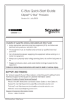
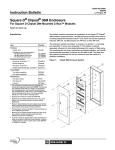
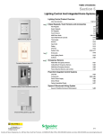
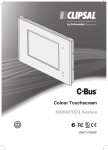
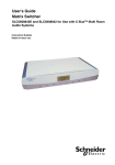
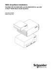
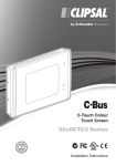
®
Clipsal Basic Single Zone
Thermostat
SLC5070THB and SLC5070THBR
Instruction Bulletin
Retain for future use.
Clipsal® Basic Single Zone Thermostat
Instruction Bulletin
63249-420-294A2
08/2008
HAZARD CATEGORIES AND SPECIAL SYMBOLS
Read these instructions carefully and look at the equipment to become
familiar with the device before trying to install, operate, service, or maintain
it. The following special messages may appear throughout this bulletin or on
the equipment to warn of potential hazards or to call attention to information
that clarifies or simplifies a procedure.
The addition of either symbol to a “Danger” or “Warning” safety label
indicates that an electrical hazard exists which will result in personal injury if
the instructions are not followed.
This is the safety alert symbol. It is used to alert you to potential personal
injury hazards. Obey all safety messages that follow this symbol to avoid
possible injury or death.
Danger indicates an immediately hazardous situation which, if not
avoided, will result in death or serious injury.
Warning indicates a potentially hazardous situation which, if not
avoided, can result in death or serious injury.
Caution indicates a potentially hazardous situation which, if not
avoided, can result in minor or moderate injury.
Caution, used without the safety alert symbol, indicates a potentially
hazardous situation which, if not avoided, can result in property
damage or improper operation.
NOTE: Provides additional information to clarify or simplify a procedure.
2
© 2008 Schneider Electric. All Rights Reserved.
63249-420-294A2
08/2008
Clipsal® Basic Single Zone Thermostat
Instruction Bulletin
PLEASE NOTE
Electrical equipment should be installed, operated, serviced, and maintained
only by qualified personnel. This document is not intended as an instruction
manual for untrained persons. No responsibility is assumed by Square D for
any consequences arising out of the use of this manual.
Class B FCC Statement
This equipment has been tested and found to comply with the limits for a
Class B digital device, pursuant to Part 15 of the FCC Rules. These limits
are designed to provide reasonable protection against harmful interference
in a residential installation. This equipment generates, uses, and can radiate
radio frequency energy and, if not installed and used in accordance with the
instructions, may cause harmful interference to radio communications.
However, there is no guarantee that interference will not occur in a particular
installation. If this equipment does cause harmful interference to radio or
television reception, which can be determined by turning the equipment off
and on, the user is encouraged to try to correct the interference by one or
more of the following measures:
•
Reorient or relocate the receiving antenna.
•
Increase the separation between the equipment and receiver.
•
Connect the equipment into an outlet on a circuit different from that to
which the receiver is connected.
•
Consult the dealer or an experienced radio/TV technician for help.
© 2008 Schneider Electric. All Rights Reserved.
3
Clipsal® Basic Single Zone Thermostat
Instruction Bulletin
63249-420-294A2
08/2008
INTRODUCTION
Clipsal® Basic Thermostats are used to regulate the air temperature
of a single zone by controlling heating/ventilation/air conditioning
(HVAC) equipment. The unit monitors the air temperature using its
internal temperature sensor.
The SLC5070THBR model has built-in relays that can be connected
directly to a HVAC system that uses a standard 24 V AC RWG
interface.
Figure 1: Clipsal® Basic Single Zone Thermostat
(SLC5070THBR) with built-in relays
Figure 2: The Clipsal® Basic Single Zone Thermostat (SLC5070THB) with external
C-Bus relays
KEY:
A. Basic thermostat
(SLC5070THB)
B. C-Bus
C. HVAC connections
D. Voltage Free Relay
with C-Bus Power
Supply
4
© 2008 Schneider Electric. All Rights Reserved.
63249-420-294A2
08/2008
Clipsal® Basic Single Zone Thermostat
Instruction Bulletin
Before You Begin
Before you begin to set up a unit, verify that your order is complete
by comparing the contents of the package with the appropriate
items in the table below. Also verify that the catalog number on the
box label matches your order.
Contents of the Box
Table 1: Contents of the Box
Part Number
Description
Quantity
SLC5070THB or
SLC5070THBR*
C-Bus Basic Single Zone Thermostat
1
*SLC5070THBR has built-in HVAC control relays.
SAFETY PRECAUTIONS
This section contains important safety precautions that must be
followed before attempting to install or maintain electrical
equipment. Carefully read and follow the safety precautions below.
HAZARD OF ELECTRIC SHOCK, EXPLOSION, OR ARC FLASH
•
Apply appropriate personal protective equipment (PPE) and
follow safe electrical work practices. See NFPA 70E.
•
This equipment must be installed and serviced by qualified
electrical personnel.
•
Turn off all electrical power supplying this equipment before
working on or inside the equipment.
•
Always use a properly rated voltage sensing device to confirm
that power is off.
•
Replace all devices, doors, and covers before turning on power
to this equipment.
Failure to follow these instructions will result in death or
serious injury.
© 2008 Schneider Electric. All Rights Reserved.
5
Clipsal® Basic Single Zone Thermostat
Instruction Bulletin
63249-420-294A2
08/2008
SELECTING A LOCATION
Follow these guidelines when selecting a location:
•
Provide easy access to the unit.
•
Avoid water, humidity, direct sunlight, and heavy dust.
•
Leave the unit uncovered to allow adequate ventilation.
•
Only use the thermostat indoors.
•
Adhere to all specifications in this manual.
•
Avoid proximity to HVAC diffusers.
•
Ensure the temperature sensor is mounted in a position suitable
for measuring the environment being temperature controlled.
This applies to the thermostat's internal sensor or to an external
C-Bus temperature sensor (whichever is used).
INSTALLATION
Network Considerations
The Desktop Touchscreen can draw 40 mA from the C-Bus
network. Determine the total network current load and verify that
there will be enough C-Bus power to support all connected devices.
Also verify that the amount of available power per C-Bus network is
no more than 2A.
C-Bus System Clock
The thermostat has a software-selectable C-Bus system clock with
the capability to synchronize data communication on the C-Bus
network. Typically the clock is disabled: Successful C-Bus network
communications require only one active clock. A maximum of three
C-Bus units per network can have the clock enabled. Refer to the CBus Toolkit software for additional information and to enable the
thermostat system clock.
6
© 2008 Schneider Electric. All Rights Reserved.
63249-420-294A2
08/2008
Clipsal® Basic Single Zone Thermostat
Instruction Bulletin
Mounting Instructions
Mount the unit on any wall surface using the appropriate hardware
(not provided). Do not recess the unit into a wall because the side
air vents must be exposed.
Mounting diagrams are provided in Figure 3 and 4.
1. Insert a flat head screwdriver into the notches at the bottom of
the thermostat and gently pry the base plate off the unit.
2. Prepare the mounting surface using the base plate to mark
mounting hardware locations.
3. Place the base plate over the mounting surface and feed the
cables through.
4. Screw the base plate to the mounting surface.
5. Wire the appropriate conductors to the terminals.
6. Align the thermostat over the base plate and push to reattach.
Figure 3: Mounting the SLC5070THBR base plate (C-Bus and
example HVAC wiring)
NOTE: HVAC relay terminal wiring will vary depending on the HVAC
system installed.
© 2008 Schneider Electric. All Rights Reserved.
7
Clipsal® Basic Single Zone Thermostat
Instruction Bulletin
63249-420-294A2
08/2008
Figure 4: Mounting the 5070THB base plate (C-Bus wiring)
Network Burden
One network burden is required for proper C-Bus operation, network
termination, and biasing.
HAZARD OF IMPROPER OR UNSTABLE OPERATION
C-Bus networks require only one burden.
Failure to follow this instruction can result in improper C-Bus
network operation.
The C-Bus system clock must be enabled in order to apply the
network burden.
8
© 2008 Schneider Electric. All Rights Reserved.
63249-420-294A2
08/2008
Clipsal® Basic Single Zone Thermostat
Instruction Bulletin
Hardware Burden
The hardware burden can be used in one of two ways.
1. Install the hardware burden temporarily in order to enable the
software burden, and then to remove the hardware burden.
2. Install the hardware burden and leave it installed as the network
burden.
To install the hardware burden device, simply plug it into the C-Bus
network RJ-45 receptacle.
NOTE: Plug the hardware burden device only into C-Bus
receptacles.
Figure 5: Hardware Burden Connection on the Unit
KEY:
A. RJ-45 C-Bus
receptacle on the unit
B. Hardware burden
Configuring, Labeling, and Recording the Locations of C-Bus Units
C-Bus units must be configured, at a minimum, with the unit address
and part name before being physically installed on the network.
Each unit is identified by a unique serial number found on the box
label (see the figure “Example of a Box Label with Lift-and-Peel
Section”). The serial number provides important information for
recording a unit's location. An infrared barcode scanner may be
used to read the box label's bar code for the serial number and unit
information.
Use the C-Bus Toolkit to assign the unit a unique address, and then
mark the unit address and part name directly onto the unit before
physical installation. You can use the lift-and-peel label from the unit
box, or write the unit address and part name directly on the unit.
© 2008 Schneider Electric. All Rights Reserved.
9
Clipsal® Basic Single Zone Thermostat
Instruction Bulletin
63249-420-294A2
08/2008
After marking the unit, record each unit's physical location onto a
site plan or panel schedule.
Figure 6: Example of a Box Label with Lift-and-Peel Section
KEY:
A. Serial number
B. Bar code
C. Lift-and-peel
section
HAZARD OF UNEXPECTED OR UNINTENDED OPERATION
•
Properly configure, label, and record the location of each unit.
•
Retain location records and provide them to the person(s)
responsible for configuring and commissioning the network.
Failure to follow these instructions can result in unintended
C-Bus network operation.
10
© 2008 Schneider Electric. All Rights Reserved.
63249-420-294A2
08/2008
Clipsal® Basic Single Zone Thermostat
Instruction Bulletin
HVAC CONNECTION
HAZARD OF IMPROPER OPERATION OR EQUIPMENT
DAMAGE.
•
Refer to the HVAC installation instructions before connecting the
wiring.
•
When the thermostat is connected to HVAC equipment, do not
press the thermostat's power button until C-Bus programming is
complete.
Failure to follow these instructions will result in damage to the
HVAC equipment or thermostat.
Interfacing the thermostat with HVAC equipment requires physical
wiring and C-Bus programming.
The thermostat can be wired to HVAC equipment that uses a
standard air conditioning RWG/RWGY control interface. It can also
be wired to some other HVAC systems, depending on their wiring
(refer to the manufacturer's wiring diagram or application notes).
Examples of connection scenarios for standard RWG/RWGY
systems are provided in this section. They use a thermostat with
built-in relays. In each case, a thermostat and C-Bus Voltage Free
Relay combination may be used instead. The thermostat provides
five relay channels (RL1, RL2, and RL3 are looped to Rc; RL4 and
RL5 looped to Rh.) An external C-Bus Voltage Free Relay may be
used to provide any additional relay channels.
© 2008 Schneider Electric. All Rights Reserved.
11
Clipsal® Basic Single Zone Thermostat
Instruction Bulletin
63249-420-294A2
08/2008
Refer to the HVAC installation instructions for wiring details specific
to your system.
Figure 7: Connecting to a 2-stage conventional A/C which uses RWG control
Figure 8: Connecting to a reverse cycle AC that uses RWG control
Figure 9: Connecting to a hydronic heating system that uses RWG control
12
© 2008 Schneider Electric. All Rights Reserved.
63249-420-294A2
08/2008
Clipsal® Basic Single Zone Thermostat
Instruction Bulletin
Figure 10: Connecting to an evaporative cooler that uses RWG control
Figure 11: Connecting to the AC system shown in Figure 10
© 2008 Schneider Electric. All Rights Reserved.
13
Clipsal® Basic Single Zone Thermostat
Instruction Bulletin
63249-420-294A2
08/2008
Figure 12: Connecting to a fan coil cooling system that uses RWG control
Figure 13: Connecting to separate RWG based cooling and heating systems
Figure 14: Example AC system without standard RWG control
14
© 2008 Schneider Electric. All Rights Reserved.
63249-420-294A2
08/2008
Clipsal® Basic Single Zone Thermostat
Instruction Bulletin
WIRING GUIDELINES
Follow the guidelines below when working with the thermostat.
•
Verify that the power supplying the system is turned OFF before
handling electrical power conductors.
•
Observe national and local electrical codes.
•
Isolate the thermostat from the Class 1 wiring. Consult your
national and local electrical codes for requirements about
isolating Class 1 wiring and Class 2 wiring terminals.
•
Consult the "Electrical Wiring Connections" figure for all
electrical connections.
•
Prevent wire cuttings and debris from entering the unit.
•
Use suitably rated copper wire, #18 - 22 AWG (0.82mm² 0.33mm²).
MEGGER® TESTING GUIDELINES
Do not Megger® test C-Bus data cabling or terminals. Megger
testing of data cabling or terminals can degrade the performance of
the C-Bus network.
It will not harm the units if electrical power terminals only are
Megger tested. But because units contain electronic components,
the Megger readings will not be correct. To obtain valid readings,
disconnect the power lines from the units.
HAZARD OF EQUIPMENT DAMAGE
Do not Megger® test C-Bus data cabling or terminals as it can
degrade the performance of the C-Bus network.
Failure to follow this instruction will result in damage to the
C-Bus network.
© 2008 Schneider Electric. All Rights Reserved.
15
Clipsal® Basic Single Zone Thermostat
Instruction Bulletin
63249-420-294A2
08/2008
CONNECTION TO THE C-BUS NETWORK
The thermostat is connected to the C-Bus network through a C-Bus
network cable that uses unshielded twisted pair (UTP) Category 5
data cable.
For optimal performance, use the connections recommended below
for each end of the cable. Attach the bootlace terminals to the
twisted pairs of the C-Bus network cable.
NOTE: The C-Bus network connection is polarity sensitive. The
polarity is marked on the unit beside the terminals.
NOTE: Do not solder wires used to connect the unit to the C-Bus
network through the terminal block connections.
HAZARD OF ELECTRIC SHOCK, EXPLOSION, OR ARC FLASH
Do not connect line voltage to any C-Bus terminal.
Failure to follow this instruction can result in personal injury or
equipment or property damage.
Figure 15: C-Bus Wiring Connections
KEY:
A. C-Bus positive (+)
B. C-Bus negative (–)
C. Remote OFF:
brown + brown-white*
D. Remote ON: green
+ green-white*
16
© 2008 Schneider Electric. All Rights Reserved.
63249-420-294A2
08/2008
Clipsal® Basic Single Zone Thermostat
Instruction Bulletin
Table 2: C-Bus Cable Conductor Assignments
Terminal
C-Bus Network
Connection
Cable Color
Not connected
Remote ON*
Green-White
Not connected
Remote ON*
Green
C-Bus Neg (–)
C-Bus Neg (–)
Orange-White
C-Bus Neg (–)
C-Bus Neg (–)
Blue-White
C-Bus Pos (+)
C-Bus Pos (+)
Blue
C-Bus Pos (+)
C-Bus Pos (+)
Orange
Not connected
Remote OFF*
Brown-White
Not connected
Remote OFF*
Brown
*Not internally connected.
SPECIFICATIONS
Table 3: Operating Specifications
Parameter
C-Bus supply voltage
Description
15 to 36 V DC, 40 mA
Does not provide current to the C-Bus network
C-Bus AC input impedance
Relays (SLC5070THPR)
50 kΩ @ 1 kHz
Each relay rated at 2 A @ 24 V AC
3750 V isolation between terminals and C-Bus
C-Bus connection
One terminal block to accommodate 0.2 to 1.3
mm2 (16 to 24 AWG)
Temperature sensor accuracy
+/- 0.9 F° (+/- 0.5 C°)
Operating temperature
14 to 122 °F (-10 to 50 °C)
Operating humidity
10 to 95% RH
© 2008 Schneider Electric. All Rights Reserved.
17
Clipsal® Basic Single Zone Thermostat
Instruction Bulletin
63249-420-294A2
08/2008
DIMENSIONS
STANDARDS
The thermostat complies with the following Standards:
Table 4: U.S. and Canadian Product Safety Standards and U.S.
FCC Regulations
Standards/Regulations
18
Title
CSA C22.2 No. 205
Signal Equipment
UL916
Energy Management Equipment
FCC Part 15
Class B Digital Device for Home or Office Use
© 2008 Schneider Electric. All Rights Reserved.
Clipsal® Basic Single Zone Thermostat
Instruction Bulletin
SUPPORT AND SERVICE
Contact the Square D Customer Information Center for technical
support by phone at 1-888-Square D (1-888-778-2733) or e-mail at
[email protected].
®
Contact your local Square D service representative or Square D
Clipsal® certified installer for repairs or service to your network.
You may also find helpful information on our web site at
www.squaredlightingcontrol.com.
Schneider Electric, USA
295 Tech Park Drive
La Vergne, TN, 37086
1-888-SquareD (1-888-778-2733)
www.squaredlightingcontrol.com
Electrical equipment should be installed, operated, serviced, and
maintained only by qualified personnel. No responsibility is assumed by
Schneider Electric for any consequences arising out of the use of this
material.
Square D,
, Clipsal, C-Bus, Saturn and Neo are trademarks or
registered trademarks of Schneider Electric and/or its affiliates in the
United States and/or other countries.
© 2008 Schneider Electric. All Rights Reserved.
63249-420-294A2
08/2008