1
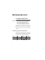
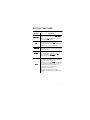
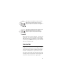
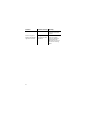
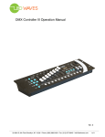
MC-Showtime
user manual
All measurements are in millimeters
120
Blackout
Sequence
Fast
Special
Medium
Slow
50
Auto
Trig
Manual
Lamp On
8.8.
Auto
Reset
Music
Trig
Music
Position
Enter
Strobe
For M4
114
78
109
143
109
P/N 35000097, Rev. A. © 2001 Martin Professional A/S, Denmark.
Introduction . . . . . . . . . . . . . . . . . . . . . . . . 4
Safety precautions . . . . . . . . . . . . . . . . . . . . . . . . 4
Unpacking . . . . . . . . . . . . . . . . . . . . . . . . . . . . . . 5
MC-Showtime setup . . . . . . . . . . . . . . . . . 6
AC power connection . . . . . . . . . . . . . . . . . . . . . . 6
Data connection . . . . . . . . . . . . . . . . . . . . . . . . . . 7
The console . . . . . . . . . . . . . . . . . . . . . . . . 8
Button functions . . . . . . . . . . . . . . . . . . . . . . . . . . 9
Fixture setup . . . . . . . . . . . . . . . . . . . . . . 11
Supported fixtures . . . . . . . . . . . . . . . . . . . . . . . 11
DMX addresses . . . . . . . . . . . . . . . . . . . . . . . . . 12
Sample configurations . . . . . . . . . . . . . . . . . . . . 13
Aligning MX-x fixtures . . . . . . . . . . . . . . . . . . . . 15
Operation . . . . . . . . . . . . . . . . . . . . . . . . . 16
Switching on the controller . . . . . . . . . . . . . . . . . 16
Pre-programmed sequences . . . . . . . . . . . . . . . 17
Trig rates . . . . . . . . . . . . . . . . . . . . . . . . . . . . . . 19
Blackout . . . . . . . . . . . . . . . . . . . . . . . . . . . . . . . 21
Strobe. . . . . . . . . . . . . . . . . . . . . . . . . . . . . . . . . 21
Fixture control . . . . . . . . . . . . . . . . . . . . . . . . . . 22
Troubleshooting . . . . . . . . . . . . . . . . . . . 23
Specifications . . . . . . . . . . . . . . . . . . . . . 25
3
INTRODUCTION
MC-Showtime controls four or more MX-x scanners
(MX-1 or MX-4, depending on the MC-Showtime
model you have) automatically, manually, or using any
or all of the 30 supplied 6-scene sequences. MCShowtime can also control CX-color changers, as well
as Synchrozap QX250 and Acrobat intelligent effects.
Note that when referring to MX-1, or MX-4 scanners
in this manual, we refer to them generically as “MX-x”
scanners. If you do not know which type of scanner
your MC-Showtime supports, then check the label on
the back of the unit.
This user manual describes the features in, and how to
use, the MC-Showtime controller.
SAFETY PRECAUTIONS
The MC-Showtime controller is not for household use.
For safe operation, read this manual before use and
follow the safety precautions listed below. If you have
questions about how to operate the controller safely,
please contact your Martin distributor or dealer.
4
•
Disconnect the fixture from AC power when not in use.
•
Always ground (earth) the fixture electrically.
•
Use only a source of AC power that complies with local
building and electrical codes and has both overload and
ground-fault protection.
•
Refer all service to a qualified technician.
•
Do not expose the device to rain or moisture.
•
Do not open the device or remove any part; there are no
user-serviceable parts inside.
UNPACKING
The MC-Showtime controller comes with:
•
1.5-meter IEC power cable
•
5-meter 3-pin XLR data cable
•
3-pin male XLR termination plug
•
User manual
5
MC-SHOWTIME SETUP
AC POWER CONNECTION
Warning!
For protection from electric shock, the
fixture must be grounded (earthed).
The AC mains supply shall have
overload and ground-fault protection.
The fixture’s mains lead must be fitted with a
gro un ding-type cord cap that fits your power
distribution cable or outlet. Consult a qualified
electrician if you have any doubts about proper
installation.
Install ing a plug on the mains lead
Following the cord cap manufacturer’s instructions,
connect the yellow and green wire to ground (earth),
the brown wire to live, and the blue wire to neutral.
The table shows some pin identification schemes.
Wire
Pin
brown
live
“L”
blue
neutral
“N”
yellow/green
ground
6
Marking
Screw color
yellow or brass
silver
green
DATA CONNECTION
A reliable data connection begins with the right cable.
Microphone cable cannot transmit data reliably over
long distances or for long periods. For best results, use
only cable designed for RS-485 applications. One
cable for connecting the first fixture is included; you
will need additional cables to connect additional
fixtures. Your Martin dealer can supply suitable cable
in various lengths.
The MC-Showtime controller data output, which is
wired pin 1 to ground, pin 2 to signal - (cold), and pin 3
to signal + (hot), is configured for direct connection to
all MC-Showtime compatible Martin fixtures (see
“Supported fixtures” on page 11).
Connecting the data link
1
Connect a data cable to the MC-Showtime controller
data output. Lead the cable to the first fixture and plug it
into the data input.
2
Connect the data output of the first fixture to the data
input of the next fixture. Continue connecting fixtures
output to input.
3
Terminate the link by inserting the male termination plug,
included, into the data output of the last fixture. A
termination plug is an XLR connector with a 120 ohm
resistor soldered across pins 2 and 3.
7
THE CONSOLE
The console on the MC-Showtime controller consists
of seven buttons and a two-digit LED display.
Blackout
Sequence
Fast
Medium
2nd
Slow
8.8.
Auto
Trig
Manual
Position
Auto
Lamp On
Music
Reset
Music
Trig
Enter
(Strobe)
Some buttons have two functions; second functions are
indicated in yellow text. To activate these second
functions, press and hold the QG button, and then
press the button for the function. The QG button
works like the shift key on a computer keyboard.
8
BUTTON FUNCTIONS
Button
Function
%ODFNRXW
Is used to blackout all the fixtures.
To re-activate the fixtures, press %ODFNRXW
again. If you press and hold this button then it
operates as the QG button.
QG
When you press and hold QG, you can access
the second functions on other buttons
(indicated with yellow text). QG operates like
the shift key on a computer keyboard.
0DQXDO
Each time 0DQXDO is pressed a trigger will be
sent and the next scene in the pre-programmed
sequence will start.
3RVLWLRQ
3RVLWLRQ is used to align the MX-x scanners.
See “Aligning MX-x fixtures” on page 15.
To use this function, hold down the QG
button, and then press 3RVLWLRQ.
$XWR
Tap $XWR a number of times to input a trigger
rate manually. The rate at which you tap the
button is used as the trigger rate.
Alternatively, if you press $XWR once and hold
it for a second, the default trigger rate for the
pre-programmed sequence will be used.
In auto trig mode the trig rate is not
synchronized with the music.
During auto trig mode, the associated
indicator in the LED display will blink at the
trig rate.
9
Button
Function
0XVLF
The 0XVLF button acts as a switch to turn
music trig mode on and off. When music trig
mode is activated, the built-in microphone is
used to synchronize the trig rate with the
music. The associated indicator in the LED
display will blink at the trig rate.
To deactivate music trig mode, press the
0XVLF button, or the $XWR button. Note that if
no trig mode is active then the fixtures will not
change to the next scene.
(QWHU
When selecting a sequence, or group of
sequences, the current selection blinks in the
LED display. Press (QWHU to start execution of
the selection. See “Selecting sequences for
execution” on page 18.
6WUREH
/DPSRQ
10
Provided that a sequence number is not
blinking in the LED display (see the
description for (QWHU), this button will
interrupt the current scene and strobe all the
fixtures as long as it is held.
/DPSRQ will activate all fixtures on the data
link (provided that they are of a supported type
and have the correct DMX address set).
To use this function, hold down the QG
button, and then press /DPSRQ.
ST
S and T are used to scroll up and down the
list of available pre-programmed sequences,
and sequence groups. See “Selecting
sequences for execution” on page 18.
5HVHW
5HVHW is used to reset all the fixtures on the
data link (provided that they are of a supported
type and have the correct DMX address set).
To use this function, hold down the QG
button, and then press 5HVHW.
FIXTURE SETUP
The MC-Showtime controller is designed to operate
together with a minimum of four MX-x scanners, as
well as a range of other fixture types. This section
details these fixtures, their associated DMX addresses,
as well as rigging considerations.
SUPPORTED FIXTURES
The following fixtures are supported by the MCShowtime controller:
•
MX-x scanners (between four and eight fixtures)
•
Acrobat intelligent effect
•
CX-2 color changer
•
CX-4 color changer
•
SyncroZap QX250 intelligent effect
The minimum configuration supported is four MX-x
scanners, but we recommend a configuration of at least
eight MX-x scanners and an Acrobat.
11
DMX ADDRESSES
Fixtures should be se t to the following DMX
addresses:
Fixture type
DMX address
MX-x
(for best results rig in DMX
pairs where the two
fixtures in each pair are
directly across from each
other.)
1, 25
7, 31
13, 36
19, 43
Acrobat
49
CX-4
55
SyncroZap
61
CX-2
67
For information on how to set DMX addresses for the
different fixture types, refer to the associated user
manual for that fixture type. These are available on the
Martin web site at: http://www.martin.dk.
You can operate the MC-Showtime controller with up
to 32 fixtures, but multiple fixtures of any type (except
MX-x scanners) will have to share DMX addresses,
and will mimic each others behavior.
SAMPLE CONFIGURATIONS
The following are three sample rigging configurations.
DMX addresses appear in parentheses.
Recommended confi guration
We recommend that you rig at least eight MX-x
scanners and an Acrobat:
Acrobat
(49)
MX-x
(1)
MX-x
(25)
MX-x
(7)
MX-x
(31)
MX-x
(13)
Effect area
MX-x
(19)
MX-x
(37)
MX-x
(43)
Minimum confi gurati on
You can effectively operate the MC-Showtime
controller with only four MX-x fixtures. These could
be rigged in a line (DMX addresses 1, 7, 13, and 19), or
in a square configuration (DMX addresses 1, 25, 19,
and 43).
13
Configurati on using all supported fixture
types
The following schematic illustrates a sample rigging
pattern that uses all of the supported fixture types:
CX-4
(55)
CX-2
(67)
Acrobat
(49)
CX-2
(67)
CX-4
(55)
MX-x
(1)
MX-x
(25)
MX-x
(7)
MX-x
(31)
Effect area
MX-x
(13)
MX-x
(37)
MX-x
(19)
MX-x
(43)
CX-4
(55)
14
CX-2
(67)
Synchro
Zap
(61)
CX-2
(67)
CX-4
(55)
ALIGNING MX- X FIXTURES
To achieve the best results the MX-x scanners are
rigged opposite each other, divided into DMX pairs.
For example an MX-x scanner with DMX address 1 is
rigged directly opposite an MX-x scanner with a DMX
address of 25. See “DMX addresses” on page 12 for a
list of the DMX pairs, and refer to the rigging samples
in the previous section. Note that this configuration is
not required and you can also expect good results when
the fixtures are rigged in a line.
To align DMX paired MX-x scanners:
1
Power on the MC-Showtime unit and activate the lamps.
2
Activate the Position function, by pressing and holding
QG and then pressing 3RVLWLRQ . When the Position
function is activated each MX- x scanner should
illuminate the scanner directly across from it. If the
fixtures are correctly aligned, shadow outlines of the
fixtures should appear in circles of light directly behind
the rig. For example, the scanner at DMX address 1
should illuminate the scanner at DMX address 25, and
vice versa.
3
If the fixtures are not in alignment then adjust their
positions on the rig so that they are correctly aligned.
4
Deactivate the Position function by pressing and holding
QG and then pressing 3RVLWLRQ.
15
OPERATION
This section describes the operating features available
with the MC-Showtime controller.
SWITCHING ON THE
CONTROLLER
To switch on the MC-Showtime unit:
1
Connect the data link to the MC-Showtime unit.
2
Power-up the fixtures.
3
Connect the power cable to the MC-Showtime unit. The
MC-Showtime controller will go into lamp-on mode (LO
will appear blinking in the LED display), and will send
lamp-on commands to the fixtures for 60 seconds, or
until you press Enter.
16
PRE-PROGRAMMED
SEQUENCES
The MC-Showtime controller is delivered with 30 preprogrammed sequences, each containing six scenes.
The sequences are numbered from 1-30.
The effects in sequences:
•
1-10 have relatively slow, smooth, rates of action and
movement. These sequences could be more
appropriate for slower music. The indicator on the
console for these sequences is labelled 6ORZ.
•
11-20 have rates of action and movement that are
neither especially slow, nor fast, smooth, nor erratic. The
indicator on the console for these sequences is labelled
0HGLXP.
•
21-30 have relatively fast, erratic, rates of
action/movement. These sequences best suit fast,
intense, dance music. The indicator on the console for
these sequences is labelled )DVW.
Note that the Fast, Medium and Slow indicators on the
console do not directly refer to the trig rate, they indicate
the “mood” (the type of movement and action).
17
Sel ecting sequences for execution
You can select any of the following sequence options
using the S and T buttons next to the LED display on
the console:
Sequence
Any individual sequence, from 1 to 30.
Fast
Medium
Slow
Auto
Trig
Music
Trig
Sequence
Fast
Medium
Slow
Auto
Trig
Music
Trig
Sequence
Fast
Medium
Slow
Auto
Trig
18
Music
Trig
Any appropriate sequence from the range of
available sequences. If you select this option the
MC-Showtime controller analyzes the trig rate and
selects a sequence with corresponding rates of
action, or movement. The type of scene selected is
indicated by the corresponding bar blinking in the
LED display ()DVW, 0HGLXP or 6ORZ).
All sequences with slow movement and action. Each
of the ten slow sequences is played 12 times.
Execution starts at sequence 1, runs through to
sequence 10 (shown as 0), and then starts again.
Sequence
Fast
Medium
All sequences with medium movement and action.
Each of the ten medium sequences is played 12
times. Execution starts at sequence 1, runs through to
sequence 10 (shown as 0), and then starts again.
Slow
Auto
Trig
Music
Trig
Sequence
Fast
Medium
All sequences with fast movement and action. Each
of the ten fast sequences is played 12 times.
Execution starts at sequence 1, runs through to
sequence 10 (shown as 0), and then starts again.
Slow
Auto
Trig
Music
Trig
When you select a new sequence, or group of
sequences, your selection blinks in the display,
indicating that it is not yet executing. To start executing
the selection press (QWHU. Whatever you have selected
will run in a continuous loop.
TRIG RATES
Triggers are used to activate scene changes. The higher
the trig rate then the faster the scenes change. There are
a range of trigger options available with the MCShowtime controller that are explained in this section.
Note that if no trig mode is active then the fixtures will
not change to the next scene at the end of executing the
current scene. They will wait for a trigger signal.
19
Synchronizing the trig rate to the musi c
In music trig mode, which is the default mode when the
MC-Showtime controller is activated, the built-in
microphone is used to synchronize the trig rate with the
music.
The 0XVLF button acts as a switch to turn music trig
mode on and off.
When this mode is activated, the associated indicator in
the LED display will blink at the trig rate.
Auto
Trig
Music
Trig
To deactivate music trig mode, press the 0XVLF button,
or the $XWR button. Note that if no trig mode is active
then the fixtures will not change to the next scene in
the sequence.
Setting your own tri g rate
To set your own trig rate, tap the $XWR button at that
rate.
Note that if you press $XWR only once and hold it for a
second, then the default trigger rate for the preprogrammed sequence will be used.
In auto trig mode the trig rate is not synchronized with
the music.
20
During auto trig mode, the associated indicator in the
LED display will blink at the trig rate.
Auto
Trig
Music
Trig
Sendi ng manual trig pulses
To send a single trigger pulse press 0DQXDO. This may
be used on its own, with no function selected, or to
supplement sound-activated triggers.
BLACKOUT
Press %ODFNRXW to black out the fixtures.
Press %ODFNRXW again to restore the light output.
STROBE
To interrupt the current scene and strobe all the
fixtures, press and hold 6WUREH . Normal operation
resumes when the key is released.
Note that this function is not available if a selection is
blinking in the LED display; in this state the button
f u n c t i o n s a s ( Q W H U. F o r m o r e i n f o r m a t i o n
see“Selecting sequences for execution” on page 18.
21
FIXTURE CONTROL
Acti vating fixtures
To activate all of the fixtures, press and hold the QG
button, and then press /DPSRQ.
Resetting fi xtures
To reset all of the fixtures, press and hold the QG
button, and then press 5HVHW.
22
TROUBLESHOOTING
Problem
LEDs fail to light.
Fixtures fail to
respond to controller.
Probable cause(s)
Remedy
No power.
Check that power is
switched on and cables
are plugged in.
Internal circuit
breaker open.
Disconnect the
controller for several
minutes to reset the
circuit breaker. Consult
service technician if
problem reoccurs.
Bad data connection.
Inspect data cables and
connections, repair or
replace damaged
cables.
The data link is not
connected.
Connect data link.
Missing termination.
Insert termination plug
in output of last fixture.
Incorrect address or
mode setting.
Check and correct DIPswitch settings.
Lights not powered
on.
Power on lights.
Lights have failed in
the protocol autodetection.
Switch off the lights
and then back on again.
In general, switch on
the MC-Showtime
controller before the
lights.
23
Problem
Fixtures respond to
blackout and manual
trig but not to music.
24
Probable cause(s)
Remedy
Volume is too low.
Place speakers closer
to fixtures or increase
volume.
Damaged
microphone or other
component.
Refer fixture for
service if problem
occurs in stand-alone
modes. Refer MCShowtime to service if
it occurs in music trig
mode.
SPECIFICATIONS
HARDWARE
•
•
•
•
Compact metal housing
7-button 2-digit display
3-pin female XLR data out connection
Built-in microphone
•
•
•
•
Easy execution of shows
Slow, medium, fast and auto-selection of show
Blackout, strobe and manual override
30 different 6-scene sequences
•
•
•
Sound
Manual
Automatic
PLAYBACK FACILITIES
TRIG SOURCES
DIMENSIONS
(L x W x H):
•
•
143 x 114 x 78 mm
(5.6 x 4.5 x 3.1 in)
WEIGHT
1 kg (2.2 lb.)
25
AC SUPPLY
•
•
•
Input: 3-prong IEC male socket
EU: 220 - 250 V / 50 Hz
US: 110 - 120 V / 60 Hz
POWER & CURRENT CONSUMPTION
•
•
3 W, 15 mA @ 230 V
6 W, 30 mA @ 120 V
•
•
•
•
1.5-meter IEC power cable
5-meter 3-pin XLR cable
3-pin male XLR termination plug
User manual
•
•
•
Table top
Flush mount
Rack mount
•
•
19” rack mount plate for 1 controller
19” rack mount plate for 2 controllers
INCLUDED ITEMS
INSTALLATION
ACCESSORIES
26