1
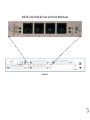
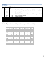
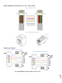
We welcome any comments you may have about our products, and we hope that you will continue to look to BayTech for your remote management needs. CONNECTION DESCRIPTION BayTech's DS74 serial module provides an interface to communicate to other devices with a serial console port. An RJ45–RJ45 cable or RJ45-RJ45 cable with RJ45–9 pin adapter is needed to connect to the devices. The DS74 is part of a Data Switch chassis and Host module systems. The DS74 ports are not standard pin outs. Baytech does have a few RJ45 cable or 9-pin adaptors available for purchase. Baytech can send a PDF document of the desired cable/adaptor or you may use the pin-out chart later in the manual to make you own cable/adaptor. CAUTION: All power should be removed from the BayTech unit prior to removing or installing cables and /or adapters. INSTALLATION Unpacking Compare the unit and serial number of the equipment you received to the packing slip located on the outside of the box. Inspect equipment carefully for damage that may have occurred in shipment. If there is damage to the equipment or if materials are missing, contact BayTech Customer Support at 228-563-7334 or call toll free inside the United States at 800-523-2702. At a minimum, you should receive the following: 1. The DS Chassis, DS71-MD4 Host Module and DS74 Modules. 2. Manual insert describing the location of the User’s Guide on BayTech’s website at www.baytech.net. 3. 1 ea. DE-9 (9 pin) PC com port adapter, 9FRJ45PC-1. 4. 1 ea. RJ-45 Roll over cable, RJ08X007 and RJ04X007. NOTE: Keep the shipping container and packing material in the event future shipment is required. Preparing the Installation Site The installation area should be clean and free of extreme temperatures and humidity. Allow sufficient space behind the DS unit for cabling and receptacle connections. Access to installation site should be restricted to authorized personnel. Installation of these units should be limited to ITE and Telco server environments. PRÉPARATION DE L'EMPLACEMENT D'INSTALLATION Le secteur d'installation devrait être propre et exempt des températures et de l'humidité extrêmes. Permettez le suffisamment d'espace derrière l'unité de DS pour des raccordements de câblage et de réceptacle. L'accès à l'emplacement d'installation devrait être limité au personnel autorisé. L'installation de ces unités devrait être limitée à ITE et à environnements de serveur de Telco. 208V VAC Model: Internal 208 VAC 50/60 Hz, 10 Amps Maximum Load. 120V VAC Model: Internal 120 VAC 50/60 Hz, 15, Amps Maximum Load. Page 5 POWER