1
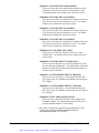
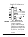
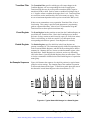
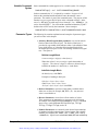
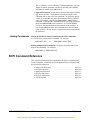
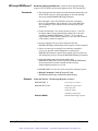
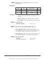
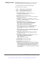
Note the following regarding interrupt line allocation:
• There are seven VXIbus backplane interrupt lines. As the resource
manager, the HP E1406A Command Module assigns itself interrupt line 1
(default). Additional interrupt lines (up to all seven) can be assigned to
the command module using the interrupt line allocation table. Interrupt
lines not assigned to programmable handlers remain unassigned.
• Many Hewlett-Packard modules have interrupt line 1 as their factory
setting. Thus, they are available for immediate use with the
HP E1406A Command Module.
• Commander modules which are programmable interrupt handlers are
assigned interrupt lines 2, 3, 4,...7; beginning with the commander
with the lowest logical address. Only one interrupt line is assigned
per interrupt handler.
• Servant modules which are programmable interrupt handlers are also
assigned interrupt lines, beginning with the servant with the lowest
logical address. Only one interrupt line is assigned per interrupt handler.
• Servant modules which are programmable interrupters are assigned
the same interrupt line assigned to their commander.
• For modules which are not programmable, the interrupt line is
selected using jumpers on the modules. The interrupt line allocation
table is used to tell the command module which line was selected.
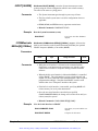
User-Defined
Interrupt Line
Allocation Table
The Interrupt Line
Allocation Table
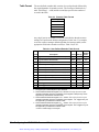
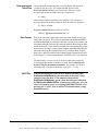
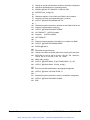
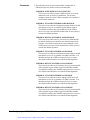
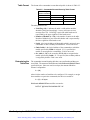
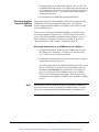
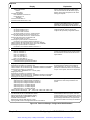
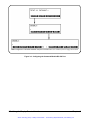
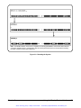
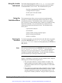
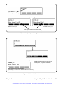
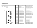
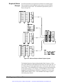
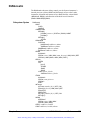
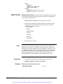
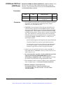
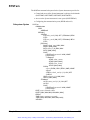
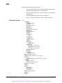
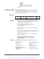
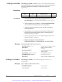
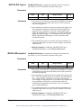
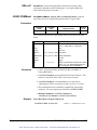
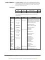
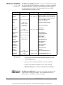
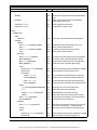
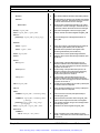
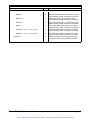
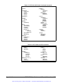
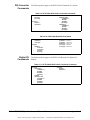
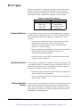
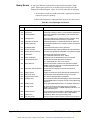
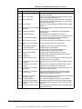
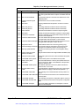
The interrupt line allocation table allows you to assign additional interrupt
lines to a specific handler, reserve interrupt lines for non-programmable
interrupt handlers and interrupters, and assign lines to VMEbus devices.
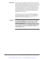
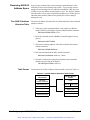
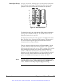
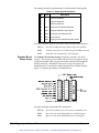
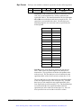
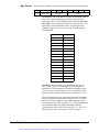
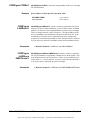
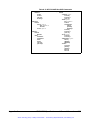
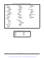
User-defined interrupt line allocations are specified with an interrupt line
table created in the command module. The table is created as follows:
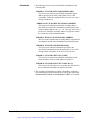
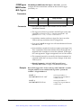
1. Table space in the command module’s non-volatile user RAM is
made available by allocating a segment of RAM with the command:
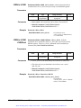
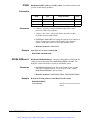
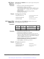
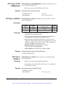
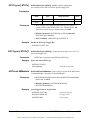
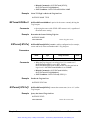
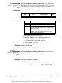
DIAGnostic:NRAM:CREate <size>
2. Reset the command module. NRAM is created during the boot-up process:
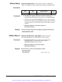
DIAGnostic:BOOT:WARM
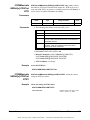
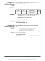
3. The location (starting address) of the table in RAM is determined
with the command:
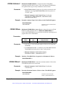
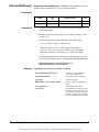
DIAGnostic:NRAM:ADDRess?
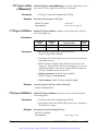
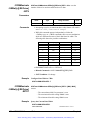
4. Data is downloaded into the table with the command:
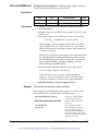
DIAGnostic:DOWNload <address>, <data>
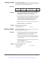
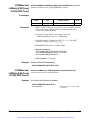
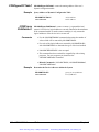
5. The table is linked to the appropriate algorithm in the command
module processor with the command:
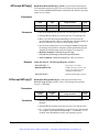
VXI:CONFigure:ITABle <address>
54
Configuring the HP E1406A Command Module
Chapter 2
Artisan Technology Group - Quality Instrumentation ... Guaranteed | (888) 88-SOURCE | www.artisantg.com