1
Contents
HP E1406A Command Module User’s Manual
Warranty . . . . . . . . . .
WARNINGS . . . . . . . .
Safety Symbols . . . . . .
Declaration of Conformity .
Reader Comment Sheet . .
.
.
.
.
.
.
.
.
.
.
.
.
.
.
.
.
.
.
.
.
.
.
.
.
.
.
.
.
.
.
.
.
.
.
.
.
.
.
.
.
.
.
.
.
.
.
.
.
.
.
.
.
.
.
.
.
.
.
.
.
.
.
.
.
.
.
.
.
.
.
.
.
.
.
.
.
.
.
.
.
.
.
.
.
.
.
.
.
.
.
.
.
.
.
.
.
.
.
.
.
.
.
.
.
.
.
.
.
.
.
.
.
.
.
.
.
.
.
.
.
.
.
.
.
.
.
.
.
.
.
.
.
.
.
.
.
.
.
.
.
.
.
.
.
.
.
.
.
.
.
.
.
.
.
.
.
.
.
.
.
9
10
10
11
13
Chapter 1. HP E1406A Command Module Overview . . . . . . . . . . . . . . . . . . . . . 15
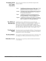
About This Chapter . . . . . . . . . . . . . . .
Warnings and Cautions . . . . . . . . . . . . .
Using HP VIC . . . . . . . . . . . . . . . . . .
Command Module Functional Description . . .
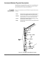
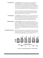
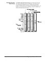
Command Module Physical Description . . . .
Faceplate Annunciators . . . . . . . . . . .
Faceplate CLK10 and Trigger Connectors .
The HP-IB and RS-232 Ports . . . . . . . .
The Run/Load Switch . . . . . . . . . . . .
The Reset Button . . . . . . . . . . . . . .
Extraction Levers . . . . . . . . . . . . . .
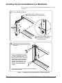
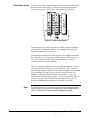
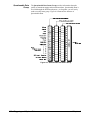
Installing the Command Module in a Mainframe
Command Module Memory . . . . . . . . . . .
Battery Backed Functions . . . . . . . . .
.
.
.
.
.
.
.
.
.
.
.
.
.
.
.
.
.
.
.
.
.
.
.
.
.
.
.
.
.
.
.
.
.
.
.
.
.
.
.
.
.
.
.
.
.
.
.
.
.
.
.
.
.
.
.
.
.
.
.
.
.
.
.
.
.
.
.
.
.
.
.
.
.
.
.
.
.
.
.
.
.
.
.
.
.
.
.
.
.
.
.
.
.
.
.
.
.
.
.
.
.
.
.
.
.
.
.
.
.
.
.
.
.
.
.
.
.
.
.
.
.
.
.
.
.
.
.
.
.
.
.
.
.
.
.
.
.
.
.
.
.
.
.
.
.
.
.
.
.
.
.
.
.
.
.
.
.
.
.
.
.
.
.
.
.
.
.
.
.
.
.
.
.
.
.
.
.
.
.
.
.
.
.
.
.
.
.
.
.
.
.
.
.
.
.
.
.
.
.
.
.
.
.
.
.
.
.
.
.
.
.
.
.
.
.
.
.
.
.
.
.
.
.
.
.
.
.
.
.
.
.
.
.
.
.
.
.
.
.
.
.
.
.
.
.
.
.
.
.
.
.
.
.
.
.
.
.
.
.
.
.
.
.
.
.
.
.
.
.
.
.
.
.
.
.
.
.
.
.
.
.
.
.
.
.
.
.
.
.
.
.
.
.
.
15
15
15
16
17
17
18
18
18
18
18
19
20
20
Chapter 2. Configuring the HP E1406A Command Module . . . . . . . . . . . . . . . . . 21
About This Chapter . . . . . . . . . . . . . . . . . . . . .
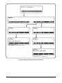
System Configuration Sequence . . . . . . . . . . . . . . .
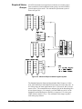
Modules Configured Statically and Dynamically . . . . . .
Identifying Statically Configured Modules . . . . . . .
Identifying Dynamically Configured Modules . . . . .
User-Defined Dynamic Configuration . . . . . . . . .
Setting VXI-MXI Configuration . . . . . . . . . . . . . .
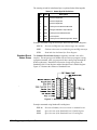
Logical Address Configuration . . . . . . . . . . . . .
A16/A24/A32 Address Window Configuration . . . .
Interrupt Register Configuration . . . . . . . . . . . .
TTL Trigger Register Configuration . . . . . . . . . .
ECL Trigger Register Configuration . . . . . . . . . .
Utility Register Configuration . . . . . . . . . . . . .
User-Defined Logical Address and Memory Windows
Setting Commander/Servant Hierarchies . . . . . . . . . .
User-Defined Commander/Servant Hierarchies . . . .
A24/A32 Address Mapping . . . . . . . . . . . . . . . . .
Reserving A24/A32 Address Space . . . . . . . . . .
.
.
.
.
.
.
.
.
.
.
.
.
.
.
.
.
.
.
.
.
.
.
.
.
.
.
.
.
.
.
.
.
.
.
.
.
.
.
.
.
.
.
.
.
.
.
.
.
.
.
.
.
.
.
.
.
.
.
.
.
.
.
.
.
.
.
.
.
.
.
.
.
.
.
.
.
.
.
.
.
.
.
.
.
.
.
.
.
.
.
.
.
.
.
.
.
.
.
.
.
.
.
.
.
.
.
.
.
.
.
.
.
.
.
.
.
.
.
.
.
.
.
.
.
.
.
.
.
.
.
.
.
.
.
.
.
.
.
.
.
.
.
.
.
.
.
.
.
.
.
.
.
.
.
.
.
.
.
.
.
.
.
.
.
.
.
.
.
.
.
.
.
.
.
.
.
.
.
.
.
.
.
.
.
.
.
.
.
.
.
.
.
.
.
.
.
.
.
.
.
.
.
.
.
.
.
.
.
.
.
.
.
.
.
.
.
.
.
.
.
.
.
.
.
.
.
.
.
.
.
.
.
.
.
.
.
.
.
.
.
.
.
.
.
.
.
.
.
.
.
.
.
.
.
.
.
.
.
.
.
.
.
.
.
.
.
.
.
.
.
21
21
22
22
22
23
27
27
29
30
30
30
31
31
38
39
44
48
HP E1406A Command Module User’s Manual Contents
1
Interrupt Line Allocation . . . . . . . . . . . . .
User-Defined Interrupt Line Allocation Table
Starting System Operation . . . . . . . . . . . . .
VXI SYSFAIL* Line . . . . . . . . . . . . . . .
.
.
.
.
.
.
.
.
.
.
.
.
.
.
.
.
.
.
.
.
.
.
.
.
.
.
.
.
.
.
.
.
.
.
.
.
.
.
.
.
.
.
.
.
.
.
.
.
.
.
.
.
.
.
.
.
.
.
.
.
.
.
.
.
.
.
.
.
.
.
.
.
.
.
.
.
.
.
.
.
53
54
60
60
Chapter 3. Using the Display Terminal Interface . . . . . . . . . . . . . . . . . . . . . . . 61
About This Chapter . . . . . . . . . . . . . . . . . . . . . . . .
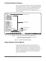
Terminal Interface Features . . . . . . . . . . . . . . . . . . . .
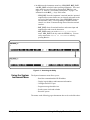
Using Display Terminal Menus . . . . . . . . . . . . . . . . . .
How Instruments Appear in the Menu . . . . . . . . . . . .
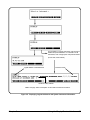
Display Terminal Menu Tutorial . . . . . . . . . . . . . . .
Using the System Instrument Menu . . . . . . . . . . . . .
Using the Loader Instrument . . . . . . . . . . . . . . . . .
Using the Switchbox Menu . . . . . . . . . . . . . . . . . .
Monitor Mode . . . . . . . . . . . . . . . . . . . . . . . . .
Executing Commands . . . . . . . . . . . . . . . . . . . . . . .
Editing the Terminal Display . . . . . . . . . . . . . . . . .
General Key Descriptions . . . . . . . . . . . . . . . . . . . . .
Menu and Menu Control Keys . . . . . . . . . . . . . . . .
Instrument Control Keys . . . . . . . . . . . . . . . . . . .
Editing Keys . . . . . . . . . . . . . . . . . . . . . . . . .
Other Keys . . . . . . . . . . . . . . . . . . . . . . . . . .
Using Supported Terminals . . . . . . . . . . . . . . . . . . . .
The Supported Terminals . . . . . . . . . . . . . . . . . . .
Using the HP 700/22 . . . . . . . . . . . . . . . . . . . . .
Using the WYSE WY-30 . . . . . . . . . . . . . . . . . . .
Using Other Terminals . . . . . . . . . . . . . . . . . . . . . .
What “ Not Supported” Means . . . . . . . . . . . . . . . .
Testing Terminals for Compatibility . . . . . . . . . . . . .
Using a Terminal Without Menus . . . . . . . . . . . . . .
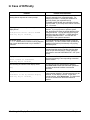
In Case of Difficulty . . . . . . . . . . . . . . . . . . . . . . . .
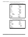
System Instrument/Switchbox Menus . . . . . . . . . . . . . . .
System Instrument Menu . . . . . . . . . . . . . . . . . . . . .
Switchbox Menu . . . . . . . . . . . . . . . . . . . . . . . . . .
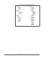
Scanning Voltmeter Menu . . . . . . . . . . . . . . . . . . . . .
HP E1326B/E1411B 51⁄2-Digit Multimeter (Stand-Alone) Menu
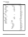
HP E1328A 4-Channel D/A Converter Menu . . . . . . . . . .
HP E1330A/B Quad 8-Bit Digital Input/Output Menu . . . . . .
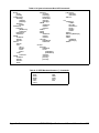
HP E1332A 4-Channel Counter/Totalizer Menu . . . . . . . . .
HP E1333A 3-Channel Universal Counter Menu . . . . . . . . .
.
.
.
.
.
.
.
.
.
.
.
.
.
.
.
.
.
.
.
.
.
.
.
.
.
.
.
.
.
.
.
.
.
.
.
.
.
.
.
.
.
.
.
.
.
.
.
.
.
.
.
.
.
.
.
.
.
.
.
.
.
.
.
.
.
.
.
.
.
.
.
.
.
.
.
.
.
.
.
.
.
.
.
.
.
.
.
.
.
.
.
.
.
.
.
.
.
.
.
.
.
.
.
.
.
.
.
.
.
.
.
.
.
.
.
.
.
.
.
.
.
.
.
.
.
.
.
.
.
.
.
.
.
.
.
.
.
.
.
.
.
.
.
.
.
.
.
.
.
.
.
.
.
.
.
.
.
.
.
.
.
.
.
.
.
.
.
.
.
.
.
.
.
.
.
.
.
.
.
.
.
.
.
.
.
.
.
.
.
.
.
.
.
.
.
.
.
.
.
.
.
.
.
.
.
.
.
.
.
.
.
.
.
.
.
.
.
.
.
.
.
.
.
.
.
.
.
.
.
.
.
.
.
.
.
.
.
.
.
.
.
.
.
.
.
.
.
.
.
.
.
.
.
.
.
.
.
.
.
.
.
.
.
.
.
.
.
.
.
.
.
.
.
.
.
.
.
.
.
.
.
.
.
.
.
.
.
.
.
.
.
.
.
.
.
.
.
.
.
.
.
.
.
.
.
.
.
.
.
.
.
.
.
.
.
.
.
.
.
.
.
.
.
.
.
.
.
.
.
.
.
.
.
.
.
.
.
.
.
.
.
.
.
.
.
.
.
.
.
.
.
.
.
.
.
.
.
.
.
.
.
.
.
.
.
.
.
.
.
.
.
.
.
.
.
.
.
.
.
.
.
.
.
.
.
.
.
.
.
.
.
.
.
.
.
.
.
.
.
.
.
.
.
.
.
.
.
.
61
62
62
63
64
65
72
72
75
76
77
77
77
78
78
78
79
79
79
81
82
82
82
83
86
87
88
91
92
94
95
96
97
99
Chapter 4. Triggering and System Status . . . . . . . . . . . . . . . . . . . . . . . . . . . 101
About This Chapter . . . . . . . . . . . . . . . . . . . .
Using VXI Backplane Trigger Lines and Ports . . . . . .
Programming the Trigger Lines and the Trigger Ports
Programming the Status System . . . . . . . . . . . . . .
General Status Register Model . . . . . . . . . . . .
Required Status Groups . . . . . . . . . . . . . . . .
2
HP E1406A Command Module User’s Manual Contents
.
.
.
.
.
.
.
.
.
.
.
.
.
.
.
.
.
.
.
.
.
.
.
.
.
.
.
.
.
.
.
.
.
.
.
.
.
.
.
.
.
.
.
.
.
.
.
.
.
.
.
.
.
.
.
.
.
.
.
.
.
.
.
.
.
.
.
.
.
.
.
.
.
.
.
.
.
.
.
.
.
.
.
.
.
.
.
.
.
.
.
.
.
.
.
.
101
101
102
104
104
106
Status System Programming Examples . .
Handling SRQs . . . . . . . . . . . .
Using Message Available (MAV) Bits
Using a Service Request (SRQ) . . .
.
.
.
.
.
.
.
.
.
.
.
.
.
.
.
.
.
.
.
.
.
.
.
.
.
.
.
.
.
.
.
.
.
.
.
.
.
.
.
.
.
.
.
.
.
.
.
.
.
.
.
.
.
.
.
.
.
.
.
.
.
.
.
.
.
.
.
.
.
.
.
.
.
.
.
.
.
.
.
.
.
.
.
.
.
.
.
.
.
.
.
.
.
.
.
.
111
111
112
114
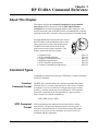
Chapter 5. HP E1406A Command Reference . . . . . . . . . . . . . . . . . . . . . . . . . 119
About This Chapter . . . . . . . . . . . .
Command Types . . . . . . . . . . . . . .
Common Command Format . . . . .
SCPI Command Format . . . . . . .
Linking Commands . . . . . . . . . .
SCPI Command Reference . . . . . . . .
DIAGnostic . . . . . . . . . . . . . . . .
:BOOT:COLD . . . . . . . . . . . .
:BOOT[:WARM] . . . . . . . . . . .
:COMMunicate :SERial[0][:OWNer]
:COMMunicate :SERial[0][:OWNer]?
:COMMunicate :SERial[n]:STORe .
:DOWNload:CHECked[:MADDress]
:DOWNload:CHECked:SADDress . .
:DOWNload [:MADDress] . . . . . .
:DOWNload :SADDress . . . . . . .
:DRAM:AVAilable? . . . . . . . . .
:DRAM:CREate . . . . . . . . . . .
:DRAM:CREate? . . . . . . . . . . .
:DRIVer:INSTall . . . . . . . . . . .
:DRIVer:LIST[:type]? . . . . . . . .
:DRIVer:LOAD . . . . . . . . . . . .
:DRIVer:LOAD :CHECked . . . . .
:FROM:AVAilable? . . . . . . . . .
:FROM:CREate . . . . . . . . . . . .
:FROM:CREate? . . . . . . . . . . .
:FROM:SIZE? . . . . . . . . . . . .
:INTerrupt:ACTivate . . . . . . . . .
:INTerrupt:PRIority[n] . . . . . . . .
:INTerrupt:PRIority[n]? . . . . . . .
:INTerrupt:RESPonse? . . . . . . . .
:INTerrupt:SETup[n] . . . . . . . . .
:INTerrupt:SETup[n]? . . . . . . . .
:NRAM:ADDRess? . . . . . . . . . .
:NRAM:CREate . . . . . . . . . . .
:NRAM:CREate? . . . . . . . . . . .
:PEEK? . . . . . . . . . . . . . . . .
:POKE . . . . . . . . . . . . . . . . .
:RDISk:ADDress? . . . . . . . . . .
:RDISk:CREate . . . . . . . . . . . .
.
.
.
.
.
.
.
.
.
.
.
.
.
.
.
.
.
.
.
.
.
.
.
.
.
.
.
.
.
.
.
.
.
.
.
.
.
.
.
.
.
.
.
.
.
.
.
.
.
.
.
.
.
.
.
.
.
.
.
.
.
.
.
.
.
.
.
.
.
.
.
.
.
.
.
.
.
.
.
.
.
.
.
.
.
.
.
.
.
.
.
.
.
.
.
.
.
.
.
.
.
.
.
.
.
.
.
.
.
.
.
.
.
.
.
.
.
.
.
.
.
.
.
.
.
.
.
.
.
.
.
.
.
.
.
.
.
.
.
.
.
.
.
.
.
.
.
.
.
.
.
.
.
.
.
.
.
.
.
.
.
.
.
.
.
.
.
.
.
.
.
.
.
.
.
.
.
.
.
.
.
.
.
.
.
.
.
.
.
.
.
.
.
.
.
.
.
.
.
.
.
.
.
.
.
.
.
.
.
.
.
.
.
.
.
.
.
.
.
.
.
.
.
.
.
.
.
.
.
.
.
.
.
.
.
.
.
.
.
.
.
.
.
.
.
.
.
.
.
.
.
.
.
.
.
.
.
.
.
.
.
.
.
.
.
.
.
.
.
.
.
.
.
.
.
.
.
.
.
.
.
.
.
.
.
.
.
.
.
.
.
.
.
.
.
.
.
.
.
.
.
.
.
.
.
.
.
.
.
.
.
.
.
.
.
.
.
.
.
.
.
.
.
.
.
.
.
.
.
.
.
.
.
.
.
.
.
.
.
.
.
.
.
.
.
.
.
.
.
.
.
.
.
.
.
.
.
.
.
.
.
.
.
.
.
.
.
.
.
.
.
.
.
.
.
.
.
.
.
.
.
.
.
.
.
.
.
.
.
.
.
.
.
.
.
.
.
.
.
.
.
.
.
.
.
.
.
.
.
.
.
.
.
.
.
.
.
.
.
.
.
.
.
.
.
.
.
.
.
.
.
.
.
.
.
.
.
.
.
.
.
.
.
.
.
.
.
.
.
.
.
.
.
.
.
.
.
.
.
.
.
.
.
.
.
.
.
.
.
.
.
.
.
.
.
.
.
.
.
.
.
.
.
.
.
.
.
.
.
.
.
.
.
.
.
.
.
.
.
.
.
.
.
.
.
.
.
.
.
.
.
.
.
.
.
.
.
.
.
.
.
.
.
.
.
.
.
.
.
.
.
.
.
.
.
.
.
.
.
.
.
.
.
.
.
.
.
.
.
.
.
.
.
.
.
.
.
.
.
.
.
.
.
.
.
.
.
.
.
.
.
.
.
.
.
.
.
.
.
.
.
.
.
.
.
.
.
.
.
.
.
.
.
.
.
.
.
.
.
.
.
.
.
.
.
.
.
.
.
.
.
.
.
.
.
.
.
.
.
.
.
.
.
.
.
.
.
.
.
.
.
.
.
.
.
.
.
.
.
.
.
.
.
.
.
.
.
.
.
.
.
.
.
.
.
.
.
.
.
.
.
.
.
.
.
.
.
.
.
.
.
.
.
.
.
.
.
.
.
.
.
.
.
.
.
.
.
.
.
.
.
.
.
.
.
.
.
.
.
.
.
.
.
.
.
.
.
.
.
.
.
.
.
.
.
.
.
.
.
.
.
.
.
.
.
.
.
.
.
.
.
.
.
.
.
.
.
.
.
.
.
.
.
.
.
.
.
.
.
.
.
.
.
.
.
.
.
.
.
.
.
.
.
.
.
.
.
.
.
.
.
.
.
.
.
.
.
.
.
.
.
.
.
.
.
.
.
.
.
.
.
.
.
.
.
.
.
.
.
.
.
.
.
.
.
.
.
.
.
.
.
.
.
.
.
.
.
.
.
.
.
.
.
.
.
.
.
.
.
.
.
.
.
.
.
.
.
.
.
.
.
.
.
.
.
.
.
.
.
.
.
.
.
.
.
.
.
.
.
.
.
.
.
.
.
.
.
.
.
.
.
.
.
.
.
.
.
.
.
.
.
.
.
.
.
.
.
.
.
.
.
.
.
.
.
.
.
.
.
.
.
.
.
.
.
.
.
.
.
.
.
.
.
.
.
.
.
.
.
.
.
.
.
.
.
.
.
.
.
.
.
.
.
.
.
.
.
.
.
.
.
.
.
.
.
.
.
.
.
.
.
.
.
.
.
.
.
.
.
.
119
119
119
119
122
122
123
124
125
125
126
126
127
129
131
132
133
134
134
135
135
136
136
137
137
137
138
138
139
139
140
141
141
142
142
143
143
144
144
145
HP E1406A Command Module User’s Manual Contents
3
:RDISk:CREate? . . . . . . . . . .
:UPLoad[:MADDress]? . . . . . . .
:UPLoad:SADDress? . . . . . . . .
OUTPut . . . . . . . . . . . . . . . . .
:ECLTrg<n> :IMMediate . . . . . .
:ECLTrg<n>:LEVel [:IMMediate] .
:ECLTrg<n>:LEVel [:IMMediate]?
:ECLTrg<n>:SOURce . . . . . . .
:ECLTrg<n> :SOURce? . . . . . .
:ECLTrg<n>[:STATe] . . . . . . .
:ECLTrg<n>[:STATe]? . . . . . . .
:EXTernal:IMMediate . . . . . . .
:EXTernal:LEVel [:IMMediate] . .
:EXTernal:LEVel [:IMMediate]? . .
:EXTernal:SOURce . . . . . . . . .
:EXTernal:SOURce? . . . . . . . .
:EXTernal[:STATe] . . . . . . . . .
:EXTernal[:STATe]? . . . . . . . .
:TTLTrg<n> :IMMediate . . . . . .
:TTLTrg<n>:LEVel [:IMMediate] .
:TTLTrg<n>:LEVel [:IMMediate]?
:TTLTrg<n>:SOURce . . . . . . .
:TTLTrg<n>:SOURce? . . . . . . .
:TTLTrg<n>[:STATe] . . . . . . .
:TTLTrg<n>[:STATe]? . . . . . . .
PROGram . . . . . . . . . . . . . . . .
[:SELected]:DEFine . . . . . . . .
[:SELected]:DEFine :CHECked . .
[:SELected]:DEFine :CHECked? . .
[:SELected]:DEFine? . . . . . . . .
[:SELected]:DELete . . . . . . . .
STATus . . . . . . . . . . . . . . . . .
:OPERation :CONDition? . . . . .
:OPERation:ENABle . . . . . . . .
:OPERation:ENABle? . . . . . . .
:OPERation[:EVENt]? . . . . . . .
:OPERation :NTRansition . . . . .
:OPERation :PTRansition . . . . . .
:PRESet . . . . . . . . . . . . . . .
:QUEStionable :CONDition? . . . .
:QUEStionable :ENABle . . . . . .
:QUEStionable :ENABle? . . . . .
:QUEStionable [:EVENt]? . . . . .
:QUEStionable :NTRansition . . . .
:QUEStionable :PTRansition . . . .
4
.
.
.
.
.
.
.
.
.
.
.
.
.
.
.
.
.
.
.
.
.
.
.
.
.
.
.
.
.
.
.
.
.
.
.
.
.
.
.
.
.
.
.
.
.
.
.
.
.
.
.
.
.
.
.
.
.
.
.
.
.
.
.
.
.
.
.
.
.
.
.
.
.
.
.
.
.
.
.
.
.
.
.
.
.
.
.
.
.
.
HP E1406A Command Module User’s Manual Contents
.
.
.
.
.
.
.
.
.
.
.
.
.
.
.
.
.
.
.
.
.
.
.
.
.
.
.
.
.
.
.
.
.
.
.
.
.
.
.
.
.
.
.
.
.
.
.
.
.
.
.
.
.
.
.
.
.
.
.
.
.
.
.
.
.
.
.
.
.
.
.
.
.
.
.
.
.
.
.
.
.
.
.
.
.
.
.
.
.
.
.
.
.
.
.
.
.
.
.
.
.
.
.
.
.
.
.
.
.
.
.
.
.
.
.
.
.
.
.
.
.
.
.
.
.
.
.
.
.
.
.
.
.
.
.
.
.
.
.
.
.
.
.
.
.
.
.
.
.
.
.
.
.
.
.
.
.
.
.
.
.
.
.
.
.
.
.
.
.
.
.
.
.
.
.
.
.
.
.
.
.
.
.
.
.
.
.
.
.
.
.
.
.
.
.
.
.
.
.
.
.
.
.
.
.
.
.
.
.
.
.
.
.
.
.
.
.
.
.
.
.
.
.
.
.
.
.
.
.
.
.
.
.
.
.
.
.
.
.
.
.
.
.
.
.
.
.
.
.
.
.
.
.
.
.
.
.
.
.
.
.
.
.
.
.
.
.
.
.
.
.
.
.
.
.
.
.
.
.
.
.
.
.
.
.
.
.
.
.
.
.
.
.
.
.
.
.
.
.
.
.
.
.
.
.
.
.
.
.
.
.
.
.
.
.
.
.
.
.
.
.
.
.
.
.
.
.
.
.
.
.
.
.
.
.
.
.
.
.
.
.
.
.
.
.
.
.
.
.
.
.
.
.
.
.
.
.
.
.
.
.
.
.
.
.
.
.
.
.
.
.
.
.
.
.
.
.
.
.
.
.
.
.
.
.
.
.
.
.
.
.
.
.
.
.
.
.
.
.
.
.
.
.
.
.
.
.
.
.
.
.
.
.
.
.
.
.
.
.
.
.
.
.
.
.
.
.
.
.
.
.
.
.
.
.
.
.
.
.
.
.
.
.
.
.
.
.
.
.
.
.
.
.
.
.
.
.
.
.
.
.
.
.
.
.
.
.
.
.
.
.
.
.
.
.
.
.
.
.
.
.
.
.
.
.
.
.
.
.
.
.
.
.
.
.
.
.
.
.
.
.
.
.
.
.
.
.
.
.
.
.
.
.
.
.
.
.
.
.
.
.
.
.
.
.
.
.
.
.
.
.
.
.
.
.
.
.
.
.
.
.
.
.
.
.
.
.
.
.
.
.
.
.
.
.
.
.
.
.
.
.
.
.
.
.
.
.
.
.
.
.
.
.
.
.
.
.
.
.
.
.
.
.
.
.
.
.
.
.
.
.
.
.
.
.
.
.
.
.
.
.
.
.
.
.
.
.
.
.
.
.
.
.
.
.
.
.
.
.
.
.
.
.
.
.
.
.
.
.
.
.
.
.
.
.
.
.
.
.
.
.
.
.
.
.
.
.
.
.
.
.
.
.
.
.
.
.
.
.
.
.
.
.
.
.
.
.
.
.
.
.
.
.
.
.
.
.
.
.
.
.
.
.
.
.
.
.
.
.
.
.
.
.
.
.
.
.
.
.
.
.
.
.
.
.
.
.
.
.
.
.
.
.
.
.
.
.
.
.
.
.
.
.
.
.
.
.
.
.
.
.
.
.
.
.
.
.
.
.
.
.
.
.
.
.
.
.
.
.
.
.
.
.
.
.
.
.
.
.
.
.
.
.
.
.
.
.
.
.
.
.
.
.
.
.
.
.
.
.
.
.
.
.
.
.
.
.
.
.
.
.
.
.
.
.
.
.
.
.
.
.
.
.
.
.
.
.
.
.
.
.
.
.
.
.
.
.
.
.
.
.
.
.
.
.
.
.
.
.
.
.
.
.
.
.
.
.
.
.
.
.
.
.
.
.
.
.
.
.
.
.
.
.
.
.
.
.
.
.
.
.
.
.
.
.
.
.
.
.
.
.
.
.
.
.
.
.
.
.
.
.
.
.
.
.
.
.
.
.
.
.
.
.
.
.
.
.
.
.
.
.
.
.
.
.
.
.
.
.
.
.
.
.
.
.
.
.
.
.
.
.
.
.
.
.
.
.
.
.
.
.
.
.
.
.
.
.
.
.
.
.
.
.
.
.
.
.
.
.
.
.
.
.
.
.
.
.
.
.
.
.
.
.
.
.
.
.
.
.
.
.
.
.
.
.
.
.
.
.
.
.
.
.
.
.
.
.
.
.
.
.
.
.
.
.
.
.
.
.
.
.
.
.
.
.
.
.
.
.
.
.
.
.
.
.
.
.
.
.
.
.
.
.
.
.
.
.
.
.
.
.
.
.
.
.
145
146
147
148
149
149
150
150
150
151
151
151
152
152
152
153
153
153
154
154
155
155
155
156
156
157
157
158
160
160
160
161
161
162
162
163
163
164
164
164
165
165
165
166
166
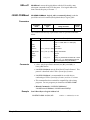
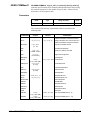
SYSTem . . . . . . . . . . . . . . . . . . . . . . . . . . . . . . . . . .
:COMMunicate:GPIB:ADDRess? . . . . . . . . . . . . . . . . . .
:COMMunicate :SERial[n]:… . . . . . . . . . . . . . . . . . . . .
:COMMunicate :SERial[n]:CONTrol :DTR . . . . . . . . . . . . .
:COMMunicate :SERial[n]:CONTrol :DTR? . . . . . . . . . . . .
:COMMunicate :SERial[n]:CONTrol :RTS . . . . . . . . . . . . .
:COMMunicate :SERial[n]:CONTrol :RTS? . . . . . . . . . . . . .
:COMMunicate :SERial[n][:RECeive] :BAUD . . . . . . . . . . .
:COMMunicate :SERial[n][:RECeive] :BAUD? . . . . . . . . . . .
:COMMunicate :SERial[n][:RECeive] :BITS . . . . . . . . . . . .
:COMMunicate :SERial[n][:RECeive] :BITS? . . . . . . . . . . .
:COMMunicate :SERial[n][:RECeive] :PACE[:PROTocol] . . . . .
:COMMunicate :SERial[n][:RECeive]:PACE[:PROTocol]? . . . .
:COMMunicate :SERial[n][:RECeive]:PACE:THReshold :STARt .
:COMMunicate :SERial[n][:RECeive] :PACE:THReshold :STARt?
:COMMunicate :SERial[n][:RECeive] :PACE:THReshold :STOP .
:COMMunicate :SERial[n][:RECeive] :PACE:THReshold :STOP?
:COMMunicate :SERial[n][:RECeive] :PARity . . . . . . . . . . .
:COMMunicate :SERial[n][:RECeive] :PARity? . . . . . . . . . .
:COMMunicate :SERial[n][:RECeive] :PARity:CHECk . . . . . .
:COMMunicate :SERial[n][:RECeive] :PARity:CHECk? . . . . . .
:COMMunicate :SERial[n][:RECeive] :SBITs . . . . . . . . . . . .
:COMMunicate :SERial[n][:RECeive] :SBITs? . . . . . . . . . . .
:COMMunicate :SERial[n]:TRANsmit :AUTO . . . . . . . . . . .
:COMMunicate :SERial[n]:TRANsmit :AUTO? . . . . . . . . . .
:COMMunicate :SERial[n]:TRANsmit :PACE[:PROTocol] . . . .
:COMMunicate :SERial[n]:TRANsmit:PACE[:PROTocol]? . . . .
:DATE . . . . . . . . . . . . . . . . . . . . . . . . . . . . . . . .
:DATE? . . . . . . . . . . . . . . . . . . . . . . . . . . . . . . . .
:ERRor? . . . . . . . . . . . . . . . . . . . . . . . . . . . . . . . .
:TIME . . . . . . . . . . . . . . . . . . . . . . . . . . . . . . . . .
:TIME? . . . . . . . . . . . . . . . . . . . . . . . . . . . . . . . .
:VERSion? . . . . . . . . . . . . . . . . . . . . . . . . . . . . . .
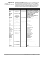
VXI . . . . . . . . . . . . . . . . . . . . . . . . . . . . . . . . . . . .
:CONFigure:CTABle . . . . . . . . . . . . . . . . . . . . . . . . .
:CONFigure:CTABle? . . . . . . . . . . . . . . . . . . . . . . . .
:CONFigure:DCTable . . . . . . . . . . . . . . . . . . . . . . . .
:CONFigure:DCTable? . . . . . . . . . . . . . . . . . . . . . . . .
:CONFigure :DLADdress? . . . . . . . . . . . . . . . . . . . . . .
:CONFigure:DLISt? . . . . . . . . . . . . . . . . . . . . . . . . .
:CONFigure :DNUMber? . . . . . . . . . . . . . . . . . . . . . . .
:CONFigure:ETABle . . . . . . . . . . . . . . . . . . . . . . . . .
:CONFigure:ETABle? . . . . . . . . . . . . . . . . . . . . . . . .
:CONFigure :HIERarchy? . . . . . . . . . . . . . . . . . . . . . .
:CONFigure :HIERarchy:ALL? . . . . . . . . . . . . . . . . . . .
:CONFigure :INFormation? . . . . . . . . . . . . . . . . . . . . .
.
.
.
.
.
.
.
.
.
.
.
.
.
.
.
.
.
.
.
.
.
.
.
.
.
.
.
.
.
.
.
.
.
.
.
.
.
.
.
.
.
.
.
.
.
.
.
.
.
.
.
.
.
.
.
.
.
.
.
.
.
.
.
.
.
.
.
.
.
.
.
.
.
.
.
.
.
.
.
.
.
.
.
.
.
.
.
.
.
.
.
.
.
.
.
.
.
.
.
.
.
.
.
.
.
.
.
.
.
.
.
.
.
.
.
.
.
.
.
.
.
.
.
.
.
.
.
.
.
.
.
.
.
.
.
.
.
.
.
.
.
.
.
.
.
.
.
.
.
.
.
.
.
.
.
.
.
.
.
.
.
.
.
.
.
.
.
.
.
.
.
.
.
.
.
.
.
.
.
.
.
.
.
.
.
.
.
.
.
.
.
.
.
.
.
.
.
.
.
.
.
.
.
.
.
.
.
.
.
.
.
.
.
.
.
.
.
.
.
.
.
.
.
.
.
.
.
.
.
.
.
.
.
.
.
.
.
.
.
.
.
.
.
.
.
.
.
.
.
.
.
.
.
.
.
.
.
.
.
.
.
.
.
.
.
.
.
.
.
.
.
.
.
.
.
.
.
.
.
.
.
.
.
.
.
.
.
.
.
.
.
.
.
.
.
.
.
.
.
.
.
.
.
.
.
.
.
.
.
.
.
.
.
.
.
.
.
.
.
.
.
.
.
.
.
.
.
.
.
.
.
.
.
.
.
.
.
.
.
.
.
.
.
.
.
.
.
.
.
.
.
.
.
.
.
.
.
.
.
.
.
.
.
.
.
.
.
.
167
168
168
169
169
170
170
171
171
172
172
173
173
174
174
175
175
176
177
177
178
178
179
179
179
180
180
181
181
182
182
183
183
184
186
187
187
188
188
189
190
191
191
192
193
193
HP E1406A Command Module User’s Manual Contents
5
:CONFigure :INFormation:ALL? . . . . . .
:CONFigure:ITABle . . . . . . . . . . . . .
:CONFigure:ITABle? . . . . . . . . . . . . .
:CONFigure :LADDress? . . . . . . . . . . .
:CONFigure :LADDress :MEXTender? . . .
:CONFigure :MEXTender :ECLTrg<n> . . .
:CONFigure :MEXTender :INTerrupt<n> . .
:CONFigure :MEXTender :TTLTrg<n> . . .
:CONFigure:MTABle . . . . . . . . . . . .
:CONFigure:MTABle? . . . . . . . . . . . .
:CONFigure:NUMBer? . . . . . . . . . . . .
:CONFigure:NUMBer :MEXTender? . . . .
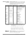
:QUERy? . . . . . . . . . . . . . . . . . . .
:READ? . . . . . . . . . . . . . . . . . . . .
:RECeive[:MESSage]? . . . . . . . . . . . .
:REGister:READ? . . . . . . . . . . . . . .
:REGister:WRITe . . . . . . . . . . . . . . .
:RESet . . . . . . . . . . . . . . . . . . . . .
:RESet? . . . . . . . . . . . . . . . . . . . .
:ROUTe:ECLTrg<n> . . . . . . . . . . . . .
:ROUTe:INTerrupt<n> . . . . . . . . . . . .
:ROUTe:TTLTrg<n> . . . . . . . . . . . . .
:SELect . . . . . . . . . . . . . . . . . . . .
:SELect? . . . . . . . . . . . . . . . . . . . .
:SEND:COMMand . . . . . . . . . . . . . .
:SEND:COMMand? . . . . . . . . . . . . .
:SEND[:MESSage] . . . . . . . . . . . . . .
:WRITe . . . . . . . . . . . . . . . . . . . .
:WSProtocol :COMMand:command . . . . .
:WSProtocol :MESSage:RECeive? . . . . . .
:WSProtocol :MESSage:SEND . . . . . . . .
:WSProtocol:QUERy:command? . . . . . . .
:WSProtocol :RESPonse? . . . . . . . . . . .
Common Command Reference . . . . . . . . . .
*CLS . . . . . . . . . . . . . . . . . . . . .
*DMC <name_string>, <command_block>
*EMC <state> . . . . . . . . . . . . . . . .
*EMC? . . . . . . . . . . . . . . . . . . . .
*ESE <mask> . . . . . . . . . . . . . . . . .
*ESE? . . . . . . . . . . . . . . . . . . . . .
*ESR? . . . . . . . . . . . . . . . . . . . . .
*GMC? <name_string> . . . . . . . . . . . .
*IDN? . . . . . . . . . . . . . . . . . . . . .
*LMC? . . . . . . . . . . . . . . . . . . . .
*LRN? . . . . . . . . . . . . . . . . . . . .
*OPC . . . . . . . . . . . . . . . . . . . . .
6
HP E1406A Command Module User’s Manual Contents
.
.
.
.
.
.
.
.
.
.
.
.
.
.
.
.
.
.
.
.
.
.
.
.
.
.
.
.
.
.
.
.
.
.
.
.
.
.
.
.
.
.
.
.
.
.
.
.
.
.
.
.
.
.
.
.
.
.
.
.
.
.
.
.
.
.
.
.
.
.
.
.
.
.
.
.
.
.
.
.
.
.
.
.
.
.
.
.
.
.
.
.
.
.
.
.
.
.
.
.
.
.
.
.
.
.
.
.
.
.
.
.
.
.
.
.
.
.
.
.
.
.
.
.
.
.
.
.
.
.
.
.
.
.
.
.
.
.
.
.
.
.
.
.
.
.
.
.
.
.
.
.
.
.
.
.
.
.
.
.
.
.
.
.
.
.
.
.
.
.
.
.
.
.
.
.
.
.
.
.
.
.
.
.
.
.
.
.
.
.
.
.
.
.
.
.
.
.
.
.
.
.
.
.
.
.
.
.
.
.
.
.
.
.
.
.
.
.
.
.
.
.
.
.
.
.
.
.
.
.
.
.
.
.
.
.
.
.
.
.
.
.
.
.
.
.
.
.
.
.
.
.
.
.
.
.
.
.
.
.
.
.
.
.
.
.
.
.
.
.
.
.
.
.
.
.
.
.
.
.
.
.
.
.
.
.
.
.
.
.
.
.
.
.
.
.
.
.
.
.
.
.
.
.
.
.
.
.
.
.
.
.
.
.
.
.
.
.
.
.
.
.
.
.
.
.
.
.
.
.
.
.
.
.
.
.
.
.
.
.
.
.
.
.
.
.
.
.
.
.
.
.
.
.
.
.
.
.
.
.
.
.
.
.
.
.
.
.
.
.
.
.
.
.
.
.
.
.
.
.
.
.
.
.
.
.
.
.
.
.
.
.
.
.
.
.
.
.
.
.
.
.
.
.
.
.
.
.
.
.
.
.
.
.
. .
. .
. .
. .
. .
. .
. .
. .
. .
. .
. .
. .
. .
. .
. .
. .
. .
. .
. .
. .
. .
. .
. .
. .
. .
. .
. .
. .
. .
. .
. .
. .
. .
. .
. .
. .
. .
. .
. .
. .
. .
. .
. .
. .
. .
. .
.
.
.
.
.
.
.
.
.
.
.
.
.
.
.
.
.
.
.
.
.
.
.
.
.
.
.
.
.
.
.
.
.
.
.
.
.
.
.
.
.
.
.
.
.
.
.
.
.
.
.
.
.
.
.
.
.
.
.
.
.
.
.
.
.
.
.
.
.
.
.
.
.
.
.
.
.
.
.
.
.
.
.
.
.
.
.
.
.
.
.
.
. . . . . . .
. . . . . . .
. . . . . . .
. . . . . . .
. . . . . . .
. . . . . . .
. . . . . . .
. . . . . . .
. . . . . . .
. . . . . . .
. . . . . . .
. . . . . . .
. . . . . . .
. . . . . . .
. . . . . . .
. . . . . . .
. . . . . . .
. . . . . . .
. . . . . . .
. . . . . . .
. . . . . . .
. . . . . . .
. . . . . . .
. . . . . . .
. . . . . . .
. . . . . . .
. . . . . . .
. . . . . . .
. . . . . . .
. . . . . . .
. . . . . . .
. . . . . . .
. . . . . . .
. . . . . . .
. . . . . . .
. . . . . . .
. . . . . . .
. . . . . . .
. . . . . . .
. . . . . . .
. . . . . . .
. . . . . . .
. . . . . . .
. . . . . . .
. . . . . . .
. . . . . . .
195
195
196
196
196
197
198
199
200
201
201
201
201
202
203
204
205
206
206
207
207
208
208
209
209
210
211
212
213
214
214
215
215
216
217
217
217
217
217
218
218
218
218
219
219
220
*OPC? . . . . . . . . . . . . . . . . . . . . . . . . .
*PMC . . . . . . . . . . . . . . . . . . . . . . . . .
*PSC <flag> . . . . . . . . . . . . . . . . . . . . .
*PSC? . . . . . . . . . . . . . . . . . . . . . . . . .
*RMC <name_string> . . . . . . . . . . . . . . . .
*RST . . . . . . . . . . . . . . . . . . . . . . . . .
*SRE <mask> . . . . . . . . . . . . . . . . . . . . .
*SRE? . . . . . . . . . . . . . . . . . . . . . . . . .
*STB? . . . . . . . . . . . . . . . . . . . . . . . . .
*TST? . . . . . . . . . . . . . . . . . . . . . . . . .
*WAI . . . . . . . . . . . . . . . . . . . . . . . . .
HP-IB Message Reference . . . . . . . . . . . . . . . . .
Device Clear (DCL) or Selected Device Clear (SDC)
Go To Local (GTL) . . . . . . . . . . . . . . . . . .
Group Execute Trigger (GET) . . . . . . . . . . . .
Interface Clear (IFC) . . . . . . . . . . . . . . . . .
Local Lockout (LLO) . . . . . . . . . . . . . . . . .
Remote . . . . . . . . . . . . . . . . . . . . . . . .
Serial Poll (SPOLL) . . . . . . . . . . . . . . . . .
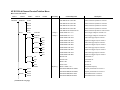
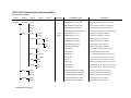
SCPI Commands Quick Reference . . . . . . . . . . . .
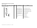
Common Commands Quick Reference . . . . . . . . . .
.
.
.
.
.
.
.
.
.
.
.
.
.
.
.
.
.
.
.
.
.
.
.
.
.
.
.
.
.
.
.
.
.
.
.
.
.
.
.
.
.
.
.
.
.
.
.
.
.
.
.
.
.
.
.
.
.
.
.
.
.
.
.
.
.
.
.
.
.
.
.
.
.
.
.
.
.
.
.
.
.
.
.
.
.
.
.
.
.
.
.
.
.
.
.
.
.
.
.
.
.
.
.
.
.
.
.
.
.
.
.
.
.
.
.
.
.
.
.
.
.
.
.
.
.
.
.
.
.
.
.
.
.
.
.
.
.
.
.
.
.
.
.
.
.
.
.
.
.
.
.
.
.
.
.
.
.
.
.
.
.
.
.
.
.
.
.
.
.
.
.
.
.
.
.
.
.
.
.
.
.
.
.
.
.
.
.
.
.
.
.
.
.
.
.
.
.
.
.
.
.
.
.
.
.
.
.
.
.
.
.
.
.
.
.
.
.
.
.
.
.
.
.
.
.
.
.
.
.
.
.
.
.
.
.
.
.
.
.
.
.
.
.
.
.
.
.
.
.
.
.
.
.
.
.
.
.
.
.
.
.
.
.
.
.
.
.
.
.
.
.
.
.
.
.
.
.
.
.
.
.
.
.
.
.
.
.
.
.
.
.
.
.
.
.
.
.
.
.
.
.
.
.
.
.
.
.
.
.
.
.
.
.
.
.
.
.
.
.
.
.
.
.
.
.
.
.
.
.
.
.
.
.
.
.
.
220
220
220
220
221
221
221
221
222
222
222
223
223
223
224
224
224
225
225
226
235
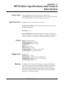
Appendix A. HP E1406A Specifications and General Information . . . . . . . . . . . . . 237
Device Type . . . . . . . . . .
Real Time Clock . . . . . . .
CLK10 . . . . . . . . . . . .
Trigger Input . . . . . . . . .
Memory . . . . . . . . . . . .
Power Requirements . . . . .
Cooling Requirements . . . .
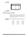
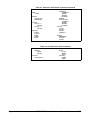
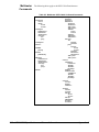
SCPI Conformance Information . .
Switchbox Configuration . . .
Multimeter Commands . . . .
Counter Commands . . . . . .
D/A Converter Commands . .
Digital I/O Commands . . . .
System Instrument Commands
.
.
.
.
.
.
.
.
.
.
.
.
.
.
.
.
.
.
.
.
.
.
.
.
.
.
.
.
.
.
.
.
.
.
.
.
.
.
.
.
.
.
.
.
.
.
.
.
.
.
.
.
.
.
.
.
.
.
.
.
.
.
.
.
.
.
.
.
.
.
.
.
.
.
.
.
.
.
.
.
.
.
.
.
.
.
.
.
.
.
.
.
.
.
.
.
.
.
.
.
.
.
.
.
.
.
.
.
.
.
.
.
.
.
.
.
.
.
.
.
.
.
.
.
.
.
.
.
.
.
.
.
.
.
.
.
.
.
.
.
.
.
.
.
.
.
.
.
.
.
.
.
.
.
.
.
.
.
.
.
.
.
.
.
.
.
.
.
.
.
.
.
.
.
.
.
.
.
.
.
.
.
.
.
.
.
.
.
.
.
.
.
.
.
.
.
.
.
.
.
.
.
.
.
.
.
.
.
.
.
.
.
.
.
.
.
.
.
.
.
.
.
.
.
.
.
.
.
.
.
.
.
.
.
.
.
.
.
.
.
.
.
.
.
.
.
.
.
.
.
.
.
.
.
.
.
.
.
.
.
.
.
.
.
.
.
.
.
.
.
.
.
.
.
.
.
.
.
.
.
.
.
.
.
.
.
.
.
.
.
.
.
.
.
.
.
.
.
.
.
.
.
.
.
.
.
.
.
.
.
.
.
.
.
.
.
.
.
.
.
.
.
.
.
.
.
.
.
.
.
.
.
.
.
.
.
.
.
.
.
.
.
.
.
.
.
.
.
.
.
.
.
.
.
.
.
.
.
.
.
.
.
.
.
.
.
.
.
.
.
.
.
.
.
.
.
.
.
.
.
.
.
.
.
.
.
.
.
.
.
.
.
237
237
237
237
237
238
238
238
238
240
242
244
244
246
Appendix B. HP E1406A Error Messages . . . . . . . . . . . . . . . . . . . . . . . . . . . 249
Using This Appendix . . . . . . . . .
Reading an Instrument’s Error Queue .
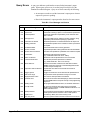
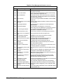
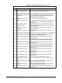
Error Types . . . . . . . . . . . . . .
Command Errors . . . . . . . . .
Execution Errors . . . . . . . . .
Device-Specific Errors . . . . . .
Query Errors . . . . . . . . . . .
Start-up Error Messages and Warnings
.
.
.
.
.
.
.
.
.
.
.
.
.
.
.
.
.
.
.
.
.
.
.
.
.
.
.
.
.
.
.
.
.
.
.
.
.
.
.
.
.
.
.
.
.
.
.
.
.
.
.
.
.
.
.
.
.
.
.
.
.
.
.
.
.
.
.
.
.
.
.
.
.
.
.
.
.
.
.
.
.
.
.
.
.
.
.
.
.
.
.
.
.
.
.
.
.
.
.
.
.
.
.
.
.
.
.
.
.
.
.
.
.
.
.
.
.
.
.
.
.
.
.
.
.
.
.
.
.
.
.
.
.
.
.
.
.
.
.
.
.
.
.
.
.
.
.
.
.
.
.
.
.
.
.
.
.
.
.
.
.
.
.
.
.
.
.
.
.
.
.
.
.
.
.
.
.
.
.
.
.
.
.
.
.
.
.
.
.
.
.
.
.
.
.
.
.
.
.
.
.
.
.
.
.
.
.
.
249
249
250
250
250
250
251
255
HP E1406A Command Module User’s Manual Contents
7
Appendix C. HP E1406A Command Module A16 Address Space . . . . . . . . . . . . . . 259
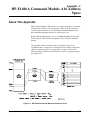
About This Appendix
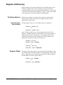
Register Addressing .
The Base Address
Register Offset .
.
.
.
.
.
.
.
.
.
.
.
.
.
.
.
.
.
.
.
.
.
.
.
.
.
.
.
.
.
.
.
.
.
.
.
.
.
.
.
.
.
.
.
.
.
.
.
.
.
.
.
.
.
.
.
.
.
.
.
.
.
.
.
.
.
.
.
.
.
.
.
.
.
.
.
.
.
.
.
.
.
.
.
.
.
.
.
.
.
.
.
.
.
.
.
.
.
.
.
.
.
.
.
.
.
.
.
.
.
.
.
.
.
.
.
.
.
.
.
.
.
.
.
.
.
.
.
.
.
.
.
.
.
.
.
.
.
.
.
.
259
260
260
260
Appendix D. Sending Binary Data Over RS-232 . . . . . . . . . . . . . . . . . . . . . . . 261
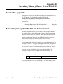
About This Appendix . . . . . . . . . . . . . . .
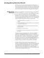
Formatting Binary Data for RS-232 Transmission
Sending Binary Data Over RS-232 . . . . . . . .
Setting Up the Mainframe . . . . . . . . . .
Index . . . . . . . . . . . . . . . . . . . . . . .
8
HP E1406A Command Module User’s Manual Contents
.
.
.
.
.
.
.
.
.
.
.
.
.
.
.
.
.
.
.
.
.
.
.
.
.
.
.
.
.
.
.
.
.
.
.
.
.
.
.
.
.
.
.
.
.
.
.
.
.
.
.
.
.
.
.
.
.
.
.
.
.
.
.
.
.
.
.
.
.
.
.
.
.
.
.
.
.
.
.
.
.
.
.
.
.
.
.
.
.
.
.
.
.
.
.
.
.
.
.
.
261
261
263
263
265
Certification
Hewlett-Packard Company certifies that this product met its published specifications at the time of shipment from the factory. HewlettPackard further certifies that its calibration measurements are traceable to the United States National Institute of Standards and Technology (formerly National Bureau of Standards), to the extent allowed by that organization’s calibration facility, and to the calibration
facilities of other International Standards Organization members.
Warranty
This Hewlett-Packard product is warranted against defects in materials and workmanship for a period of three years from date of shipment. Duration and conditions of warranty for this product may be superseded when the product is integrated into (becomes a part of)
other HP products. During the warranty period, Hewlett-Packard Company will, at its option, either repair or replace products which
prove to be defective.
For warranty service or repair, this product must be returned to a service facility designated by Hewlett-Packard (HP). Buyer shall prepay shipping charges to HP and HP shall pay shipping charges to return the product to Buyer. However, Buyer shall pay all shipping
charges, duties, and taxes for products returned to HP from another country.
HP warrants that its software and firmware designated by HP for use with a product will execute its programming instructions when
properly installed on that product. HP does not warrant that the operation of the product, or software, or firmware will be uninterrupted
or error free.
Limitation Of Warranty
The foregoing warranty shall not apply to defects resulting from improper or inadequate maintenance by Buyer, Buyer-supplied products or int`erfacing, unauthorized modification or misuse, operation outside of the environmental specifications for the product, or improper site preparation or maintenance.
The design and implementation of any circuit on this product is the sole responsibility of the Buyer. HP does not warrant the Buyer’s
circuitry or malfunctions of HP products that result from the Buyer’s circuitry. In addition, HP does not warrant any damage that occurs as a result of the Buyer’s circuit or any defects that result from Buyer-supplied products.
NO OTHER WARRANTY IS EXPRESSED OR IMPLIED. HP SPECIFICALLY DISCLAIMS THE IMPLIED WARRANTIES OF
MERCHANTABILITY AND FITNESS FOR A PARTICULAR PURPOSE.
Exclusive Remedies
THE REMEDIES PROVIDED HEREIN ARE BUYER’S SOLE AND EXCLUSIVE REMEDIES. HP SHALL NOT BE LIABLE
FOR ANY DIRECT, INDIRECT, SPECIAL, INCIDENTAL, OR CONSEQUENTIAL DAMAGES, WHETHER BASED ON CONTRACT, TORT, OR ANY OTHER LEGAL THEORY.
Notice
The information contained in this document is subject to change without notice. HEWLETT-PACKARD (HP) MAKES NO WARRANTY OF ANY KIND WITH REGARD TO THIS MATERIAL, INCLUDING, BUT NOT LIMITED TO, THE IMPLIED WARRANTIES OF MERCHANTABILITY AND FITNESS FOR A PARTICULAR PURPOSE. HP shall not be liable for errors contained
herein or for incidental or consequential damages in connection with the furnishing, performance or use of this material. This document contains proprietary information which is protected by copyright. All rights are reserved. No part of this document may be photocopied, reproduced, or translated to another language without the prior written consent of Hewlett-Packard Company. HP assumes no
responsibility for the use or reliability of its software on equipment that is not furnished by HP.
U.S. Government Restricted Rights
The Software and Documentation have been developed entirely at private expense. They are delivered and licensed as "commercial
computer software" as defined in DFARS 252.227-7013 (October 1988), DFARS 252.211.7015 (May 1991) or DFARS 252.227-7014
(June 1995), as a "commercial item" as defined in FAR 2.101(a), or as "Restricted computer software" as defined in FAR 52.227-19
(June 1987) (or any equivalent agency regulation or contract clause), whichever is applicable. You have only those rights provided for
such Software and Documentation by the applicable FAR or DFARS clause or the HP standard software agreement for the product involved.
HP E1406A User’s Manual
Edition 4
Copyright © 1996 Hewlett-Packard Company. All Rights Reserved.
HP E1406A User’s Manual
9
Documentation History
All Editions and Updates of this manual and their creation date are listed below. The first Edition of the manual is Edition 1. The Edition number increments by 1 whenever the manual is revised. Updates, which are issued between Editions, contain replacement pages
to correct or add additional information to the current Edition of the manual. Whenever a new Edition is created, it will contain all of
the Update information for the previous Edition. Each new Edition or Update also includes a revised copy of this documentation history page.
Edition 1
Edition 2
Edition 3
Edition 4
. . . . . . . . . . . . . . . . . . . . . . . . . . . . . . . . . . . . . . . . . . . . . . . . June 1992
. . . . . . . . . . . . . . . . . . . . . . . . . . . . . . . . . . . . . . . . . . . . February 1993
. . . . . . . . . . . . . . . . . . . . . . . . . . . . . . . . . . . . . . . . . . . . . October 1994
. . . . . . . . . . . . . . . . . . . . . . . . . . . . . . . . . . . . . . . . . . . . . . . . May 1996
Trademark Information
Mircosoft® and MS-DOS® are U.S. registered trademarks of Microsoft Corp.
Safety Symbols
Instruction manual symbol affixed to product. Indicates that the user must refer to the
manual for specific WARNING or CAUTION information to avoid personal injury
or damage to the product.
Alternating current (AC).
Direct current (DC).
Indicates hazardous voltages.
Indicates the field wiring terminal that must
be connected to earth ground before operating the equipment—protects against electrical shock in case of fault.
or
Frame or chassis ground terminal—typically
connects to the equipment’s metal frame.
WARNING
Calls attention to a procedure, practice, or condition that could cause bodily injury or death.
CAUTION
Calls attention to a procedure, practice, or condition that could possibly cause damage to
equipment or permanent loss of data.
WARNINGS
The following general safety precautions must be observed during all phases of operation, service, and repair of this product.
Failure to comply with these precautions or with specific warnings elsewhere in this manual violates safety standards of design,
manufacture, and intended use of the product. Hewlett-Packard Company assumes no liability for the customer’s failure to
comply with these requirements.
Ground the equipment: For Safety Class 1 equipment (equipment having a protective earth terminal), an uninterruptible safety earth
ground must be provided from the mains power source to the product input wiring terminals or supplied power cable.
DO NOT operate the product in an explosive atmosphere or in the presence of flammable gases or fumes.
For continued protection against fire, replace the line fuse(s) only with fuse(s) of the same voltage and current rating and type.
DO NOT use repaired fuses or short-circuited fuse holders.
Keep away from live circuits: Operating personnel must not remove equipment covers or shields. Procedures involving the removal
of covers or shields are for use by service-trained personnel only. Under certain conditions, dangerous voltages may exist even with the
equipment switched off. To avoid dangerous electrical shock, DO NOT perform procedures involving cover or shield removal unless
you are qualified to do so.
DO NOT operate damaged equipment: Whenever it is possible that the safety protection features built into this product have been impaired, either through physical damage, excessive moisture, or any other reason, REMOVE POWER and do not use the product until
safe operation can be verified by service-trained personnel. If necessary, return the product to a Hewlett-Packard Sales and Service Office for service and repair to ensure that safety features are maintained.
DO NOT service or adjust alone: Do not attempt internal service or adjustment unless another person, capable of rendering first aid
and resuscitation, is present.
DO NOT substitute parts or modify equipment: Because of the danger of introducing additional hazards, do not install substitute
parts or perform any unauthorized modification to the product. Return the product to a Hewlett-Packard Sales and Service Office for
service and repair to ensure that safety features are maintained.
10
HP E1406A User’s Manual
Declaration of Conformity
according to ISO/IEC Guide 22 and EN 45014
Manufacturer’s Name:
Hewlett-Packard Company
Loveland Manufacturing Center
Manufacturer’s Address:
815 14th Street S.W.
Loveland, Colorado 80537
declares, that the product:
Product Name:
HP-IB Command Module
Model Number:
E1406A
Product Options:
All
conforms to the following Product Specifications:
Safety:
IEC 1010-1 (1990) Incl. Amend 1 (1992)/EN61010-1 (1993)
CSA C22.2 #1010.1 (1992)
UL 3111
EMC:
CISPR 11:1990/EN55011 (1991): Group 1 Class A
IEC1000-4-2:1995/prEN50082-1 (1995): 4 kV CD, 8 kV AD
ENV50140:1993/prEN50082-1 (1995): 3 V/m
IEC1000-4-4:1995/prEN50082-1 (1995): 1 kV Power Line
0.5 kV Signal Lines
ENV50141:1993/prEN50082-1 (1995): 3 Vrms
ENV50142:1994/prEN50082-1 (1995): 1 kV CM, 0.5 kV DM
IEC1000-4-8:1993/prEN50082-1 (1995): 3 A/m
EN61000-4-11:1994/prEN50082-1 (1995): 30%, 10 ms 60%, 100 ms
Supplementary Information: The product herewith complies with the requirements of the Low Voltage Directive
73/23/EEC and the EMC Directive 89/336/EEC (inclusive 93/68/EEC) and carries the "CE" marking accordingly.
Tested in a typical HP C-Size VXI Mainframe configuration.
December 30, 1995
Jim White, QA Manager
European contact: Your local Hewlett-Packard Sales and Service Office or Hewlett-Packard GmbH,
Department HQ-TRE, Herrenberger Straße 130, D-71034 Böblingen, Germany (FAX +49-7031-14-3143).
HP E1406A User’s Manual
11
Notes
12
HP E1406A User’s Manual
Please fold and tape for mailing
Reader Comment Sheet
HP E1406A User’s Manual
Edition 4
You can help us improve our manuals by sharing your comments and suggestions. In appreciation of your time, we will
enter you in a quarterly drawing for a Hewlett-Packard Palmtop Personal Computer (U.S. government employees
cannot participate in the drawing).
Your Name
City, State/Province
Company Name
Country
Job Title
Zip/Postal Code
Address
Telephone Number with Area Code
Please list the system controller, operating system, programming language, and plug-in modules you are using.
fold here
cut along this line
NO POSTAGE
NECESSARY
IF MAILED
IN THE
UNITED STATES
BUSINESS REPLY MAIL
FIRST CLASS
PERMIT NO. 37
LOVELAND, CO
HEWLETT-PACKARD COMPANY
Measurement Systems Division
Learning Products Department
P.O. Box 301
Loveland, CO 80539-9984
fold here
Please pencil-in one circle for each statement below:
• The documentation is well organized.
• Instructions are easy to understand.
• The documentation is clearly written.
• Examples are clear and useful.
• Illustrations are clear and helpful.
• The documentation meets my overall expectations.
Please write any comments or suggestions below--be specific.
Disagree
O
O
O
O
O
O
O
O
O
O
O
O
O
O
O
O
O
O
O
O
O
O
O
O
Agree
O
O
O
O
O
O
14
HP E1406A User’s Manual
Chapter 1
HP E1406A Command Module Overview
About This Chapter
This chapter contains WARNINGS and CAUTIONS, a functional and physical
overview of the HP E1406A Command Module, and instructions on installing
the command module in a mainframe. Chapter contents are as follows:
•
•
•
•
•
•
Warnings and Cautions . . . . . . . . . . . . . . . . . . . . . . . . . . . . .
Using HP VIC . . . . . . . . . . . . . . . . . . . . . . . . . . . . . . . . . . . .
Command Module Functional Description . . . . . . . . . . . . . .
Command Module Physical Description. . . . . . . . . . . . . . . .
Installing the Command Module in a Mainframe . . . . . . . . .
Command Module Memory. . . . . . . . . . . . . . . . . . . . . . . . . .
Page 15
Page 15
Page 16
Page 17
Page 19
Page 20
Warnings and Cautions
WARNING
SHOCK HAZARD. Only qualified, service-trained personnel
who are aware of the hazards involved should install, configure,
or remove the multiplexer module. Disconnect all power
sources from the mainframe, the terminal modules, and
installed modules before installing or removing a module.
CAUTION
STATIC ELECTRICITY. Static electricity is a major cause of component
failure. To prevent damage to the electrical components in the multiplexer,
observe anti-static techniques whenever removing, configuring, and
installing a module. The multiplexer is susceptible to static discharges.
Do not install the multiplexer module without its metal shield attached.
Using HP VIC
Our goal is to make installation of your C-size VXI system as easy as possible.
To o so, HP VIC (HP VXI Installation Consultant) is provided with the
HP E1406A Command Module. HP VIC is a Microsoft® Windows
program that helps you configure and install the HP E1406A Command
Module - based on VXI systems. If your system contains an HP E1406A
Command Module to be controlled by a computer external to the VXI
mainframe, it is recommended you configure your system using HP VIC.
Chapter 1
HP E1406A Command Module Overview
15
Command Module Functional Description
The HP E1406A Command Module is the foundation of a VXIbus system
(see Figure 1-1). Though its role in a VXIbus system is largely transparent
(for example, the user need not program its functions) it provides the
following key functions:
• Translates SCPI (Standard Commands for Programmable
Instruments) commands for HP register-based instruments.
• Provides the VXIbus slot 0 and resource manager capabilities.
• Can drive the VXIbus TTLTRG0-7 and ECLTRG0-1 trigger lines.
The module contains SMB connectors for placing an external trigger
onto the selected line(s), and for routing an internal trigger to a
device external to the mainframe.
• Contains an internal clock that allows you to set and read the time
and date.
• Is the Hewlett-Packard Interface Bus (HP-IB) to VXIbus interface.
Figure 1-1. VXIbus System
16
HP E1406A Command Module Overview
Chapter 1
Command Module Physical Description
The HP E1406A Command Module occupies one C-size mainframe slot.
The faceplate has annunciators, clock and trigger connectors, interface
ports, and extraction levers that are described below.
Faceplate
Annunciators
There are four annunciators on the HP E1406A faceplate which show the
following:
Failed
Shows that the command module has failed its power-on
self-test or has stopped working at some point in time.
SYSFAIL
Shows that the SYSFAIL line on the VXIbus backplane is
being asserted by the command module when it fails.
Access
Shows that the command module is accessing, or being
accessed by the VXIbus backplane.
Ready
Shows that the command module is in the VXIbus normal
operation state.
Figure 1-2. HP E1406A Command Module Faceplate
Chapter 1
HP E1406A Command Module Overview
17
Faceplate CLK10
and Trigger
Connectors
18
There are four signal connectors on the HP E1406A faceplate which
function as follows:
Clk In
This SMB connector allows an external 10 MHz clock to function
as the system’s slot 0 CLK10 resource. This is a high
impedance input with an input range from ± 40 mV to ± 42.5 V.
Clk Out
This SMB connector allows the internal slot 0 CLK10 resource
to be routed to other VXIbus mainframes. This output is a
TTL level output and drives 50 Ω.
Trig In
This SMB connector allows an external trigger signal (TTL
levels) to be applied to the system on the trigger line selected
(TTLTRG0-7/ECLTRG0-1). The input impedance is 5 kΩ.
Trig Out
This SMB connector allows an internal trigger on the trigger line
specified (TTLTRG0-7/ECLTRG0-1) to be applied to an external
device. This output is a TTL level output and drives 50 Ω.
The HP-IB and
RS-232 Ports
The HP-IB port allows an HP-IB cable to be connected from the
HP E1406A to a computer, or to an external disk drive. The RS-232 port
can be used as a user interface, or used for peripheral control if the
HP E1406A contains Instrument BASIC (IBASIC). The RS-232 port is a
9-pin DTE connector. Supported terminals include: HP 700/92, HP 700/94,
HP 700/22, HP 700/43, Wyse WY-30, DEC VT 100, and DEC VT 220.
The Run/Load
Switch
The run/load switch is located beneath the HP-IB port. This switch lets you
activate the loader instrument so that you can reprogram the Flash ROM or
download device drivers to the Flash ROM.
The Reset Button
The reset button is located beneath the run/load switch. This button is used
to reconfigure your VXIbus system and return it to the power-on state.
Extraction Levers
The extraction levers provide easy insertion into and extraction from the
C-size mainframe.
HP E1406A Command Module Overview
Chapter 1
Installing the Command Module in a Mainframe
Refer to Figure 1-3 to install the HP E1406A Command Module in a C-size
mainframe.
Set the extraction levers out.
Slide the HP E1406A into any slot
until the backplane connectors touch.
Seat the command module into
the mainframe by pushing in
the extraction levers.
Tighten the top and bottom screws to
secure the command module to the
mainframe.
NOTE: The extraction levers will
not seat the backplane connectors
on older VXIbus mainframes. You
must manually seat the connectors
by pushing in the module until the
module’s front panel is flush with
the front of the mainframe. The
extraction levers may be used to
guide or remove the command
module.
To remove the command module from the mainframe,
reverse the procedure.
Figure 1-3. Installing the Command Module in a VXIbus Mainframe
Chapter 1
HP E1406A Command Module Overview
19
Command Module Memory
The HP E1406A comes from the factory equipped with 512 KB of RAM
and 1.25 MB of Flash ROM. HP E1406A Option 010 provides 1.75 MB of
Flash ROM and 1 MB of RAM.
For applications which do not require shared RAM, the non-volatile RAM
can be configured to a full 2 MB if the extra 512 KB of RAM and 512 KB of
Flash ROM has been installed.
Battery Backed
Functions
20
The HP E1406A clock and calendar functions, the user non-volatile RAM
(NRAM), and the device driver RAM (DRAM) are backed up by a NiCad
battery. For systems with 512 KB of memory this battery has a ten month
lifetime and is fully recharged when the command module is in the
mainframe and the power has been on for fifteen continuous hours. This
battery has a five month lifetime for systems with 1 MB of RAM and
2.5 month lifetime for systems with 2 MB of RAM.
HP E1406A Command Module Overview
Chapter 1
Chapter 2
Configuring the HP E1406A Command
Module
About This Chapter
One purpose of the HP E1406A is to provide the
resource manager function required by VXIbus
systems. This chapter describes the resource
manager’s function and shows you how to modify
the configuration process with user tables you
download into non-volatile user RAM. All of these
functions require the Flash ROMS Run/Load switch
be set to "Run".
The main sections of this chapter include:
•
•
•
•
•
•
•
•
System Configuration Sequence . . . . . . . . . . . . . . . . . . . . . .
Modules Configured Statically and Dynamically . . . . . . . . .
Setting VXI-MXI Configuration . . . . . . . . . . . . . . . . . . . . . .
Setting Commander/Servant Hierarchies . . . . . . . . . . . . . . .
A24/A32 Address Mapping . . . . . . . . . . . . . . . . . . . . . . . . . .
Interrupt Line Allocation . . . . . . . . . . . . . . . . . . . . . . . . . . . .
Starting System Operation . . . . . . . . . . . . . . . . . . . . . . . . . . .
VXI SYSFAIL* Line . . . . . . . . . . . . . . . . . . . . . . . . . . . . . . .
Page 21
Page 22
Page 27
Page 38
Page 44
Page 53
Page 60
Page 60
System Configuration Sequence
As mentioned in the C-Size VXIbus Systems Configuration Guide, the
resource manager within the HP E1406A Command Module performs the
following system configuration sequence when power is applied:
• Identify all statically and dynamically configured plug-in modules
installed in the C-size mainframe.
• Set commander/servant hierarchies whereby one or more plug-in
modules control other plug-in modules.
• Perform A24/A32 address mapping so modules requiring additional
addressing can receive it.
• Allocate interrupt lines to manage communication between interrupt
handler modules and interrupter modules.
• Start system operation.
Once the power-on sequence is completed and the system is started, the
resource manager is no longer used.
Chapter 2
Configuring the HP E1406A Command Module
21
The following sections describe each step of the configuration sequence.
Included are examples on how to change the sequence using configuration
tables stored in non-volatile user RAM.
Note
Refer to the C-Size VXIbus Systems Configuration Guide for information on
configuring the HP E1406A Command Module as the resource manager.
Modules Configured Statically and Dynamically
Statically configured modules are plug-in modules whose logical addresses
are set with logical address switches. Dynamically configured modules are
plug-in modules whose logical addresses are programmed (set) by the
resource manager.
Identifying
Statically
Configured Modules
Once all power-on self tests have completed, the resource manager
identifies all statically configured modules. The resource manager retains
information such as the module’s logical address, slot number, model
number, manufacturer’s code, and so forth.
Identifying
Dynamically
Configured Modules
Once all statically configured modules have been located in a mainframe
and none have a logical address of 255, the resource manager identifies all
dynamically configured modules and assigns them logical addresses as
follows.
• The resource manager locates dynamically configured modules by
scanning each mainframe slot. Refer to the plug-in module manual
for additional information on setting up the module prior to its
dynamic configuration.
• Beginning with the lowest mainframe slot (excluding slot 0), the
resource manager scans each slot via the module identification
(MODID) bus until a dynamically configured module is located.
The module is assigned a logical address that is the lowest available
multiple of 8.
• The resource manager continues scanning until the next dynamically
configured module is located. The module is assigned a logical
address that is the next available multiple of 8. The process continues
until all dynamically configured devices have been assigned logical
addresses. If all multiples of 8 are used, the dynamically configured
module is assigned the first available address.
• Logical addresses used by statically configured devices will not be
assigned to dynamically configured devices.
• Dynamically configured devices will not be assigned logical address 255.
• A set of address blocked dynamically configured devices will be
assigned successive logical addresses beginning with the lowest
available multiple of 8.
22
Configuring the HP E1406A Command Module
Chapter 2
User-Defined
Dynamic
Configuration
If your system contains instruments comprised of multiple modules that
must have successive logical addresses, then the modules must be statically
configured using their logical address switches, or be dynamically
configured with the user-defined dynamic configuration table. The dynamic
configuration table covered in this section allows you to override the default
configuration process by assigning logical addresses as you choose.
The Dynamic
Configuration Table
User-defined dynamic configurations are specified with a dynamic
configuration table created in the command module. The table is created as
follows:
1. Table space in the command module’s non-volatile user RAM is
made available by allocating a segment of RAM with the command:
DIAGnostic:NRAM:CREate <size>
2. Reset the command module. NRAM is created during the boot-up
process:
DIAGnostic:BOOT:WARM
3. The location (starting address) of the table in RAM is determined
with the command:
DIAGnostic:NRAM:ADDRess?
4. Data is downloaded into the table with the command:
DIAGnostic:DOWNload <address>,<data>
5. The table is linked to the appropriate algorithm in the command
module processor with the command:
VXI:CONFigure:DCTable <address>
Table Format
The format of the dynamic configuration table is shown in Table 2-1.
Table 2-1. Dynamic Configuration Table Format
Valid Flag
Number of
Entries
Slot Number
Slot 0 Laddr
Laddr
Block Size
Slot Number
Slot 0 Laddr
Laddr
Block Size
•
•
•
•
•
•
•
•
Slot Number
Slot 0 Laddr
Laddr
Block Size
The table parameters are:
• Valid Flag (1/0) 1 (one) indicates the table is valid and the modules
can be configured accordingly. 0 (zero) will cause an error message
(Error 39). Valid Flag is part of the table header and is one byte.
• Number of Entries (1 - 254) is the number of entries in the table.
Number of Entries is part of the table header and is one byte.
Chapter 2
Configuring the HP E1406A Command Module
23
• Slot Number (1 - 12) is the mainframe slot the module to be
assigned an address is installed in. Field is one byte.
• Slot 0 Laddr is the logical address of the slot 0 device. This is 0
(zero) in mainframe #1 but will be different in any additional
mainframes. Field is one byte.
• Laddr (1 - 254) is the logical address to which the module in Slot
Number is set. Field is one byte.
• Block Size (1 - 128) is the number of devices in an address block.
When there is more than one device, Laddr specifies the logical
address of the first device in the set. The remaining devices are
assigned sequential logical addresses beginning with the next highest
address. When there are multiple devices in a slot that are not
address blocked, there must be an entry in the table for each device.
Field is one byte.
Determining the
Table Size
The dynamic configuration table has a two byte header and each of the four
fields are one byte. The amount of RAM to allocate with
DIAGnostic:NRAM:CREate is computed as:
2 + 4(N)
where N is the number of modules to be configured. For example, to
dynamically configure three modules based on logical addresses you have
selected, the table size would be: 2 + 4(3) = 14 bytes.
DIAGnostic:NRAM:CREate would be executed as:
OUTPUT @E1406;"DIAG:NRAM:CRE 14"
24
Data Format
Data can be sent to the dynamic configuration table in any convenient
format, as long as the binary data is preserved. This can be accomplished
using DIAGnostic:PEEK? and DIAGnostic:POKE, by reading the data into a
variable in the computer and then downloading the data to the table using
the Arbitrary Block Program Data format, and so forth. In the following
example, this is accomplished by reading the data into 16-bit integer
variables in the computer and then downloading the data to the table using
the ANSI/IEEE 488.2-1987 Arbitrary Block Program Data format. More
information on the Arbitrary Block Program format can be found on
page 121 of this manual and in the ANSI/IEEE 488.2-1987 document.
CAUTION
When downloading data into the dynamic configuration table,
DIAGnostic:DOWNload does not determine if the table is large
enough to store the data. If the amount of data sent by
DIAGnostic:DOWNload is greater than the (table) space allocated
by DIAGnostic:NRAM:CREate, system errors will occur. You can
recover from these errors by executing DIAGnostic:BOOT:COLD,
or by pressing the "Ctrl-R" keys on an RS-232 terminal while
cycling mainframe power.
Configuring the HP E1406A Command Module
Chapter 2
Example: Dynamically
Configuring a Module
The following program dynamically sets the logical address of the
HP E1412A 61⁄2-Digit Multimeter in slot 6 to 32. The program notes each
of the steps used to create and load the table.
To dynamically configure the multimeter, its logical address must be set
to 255 using the logical address switches.
Chapter 2
10
20
!Assign an I/O path and allocate a variable to store dynamic configuration
!data to be downloaded to the command module.
30
ASSIGN @E1406 TO 70900;EOL
40
INTEGER Dy_config(1:6)
50
60
70
!
!Allocate a segment of non-volatile user RAM on the command
!module to store the dynamic configuration table (1 module).
80
OUTPUT @E1406;"DIAG:NRAM:CRE 6"
CHR$(10) END
90
100
110
!
!Restart the system instrument to allocate the user RAM. Wait for the
!restart to complete before continuing.
120
OUTPUT @E1406;"DIAG:BOOT:WARM"
130
ON TIMEOUT 7,.1 GOTO Complete
140
Complete: B=SPOLL(70900)
150
OFF TIMEOUT 7
160
170
!
!Return the starting address of the table in non-volatile user RAM.
180
OUTPUT @E1406;"DIAG:NRAM:ADDR?"
190
ENTER @E1406;A
200
210
220
230
!
!Download the following bytes: the table is valid, one module is dynamically
!configured, it’s installed in slot 6, the logical address of the slot 0 module
!is 0, the logical address to be set is 32, and the block size is 1.
240
DATA 257,1,6,0,32,1
250
READ Dy_config(*)
260
OUTPUT @E1406 USING "#,3(K)";"DIAG:DOWN ";A;" ,#0"
270
OUTPUT @E1406 USING "B";Dy_config(*)
280
290
!
!Link the dynamic configuration table to the appropriate algorithm.
300
OUTPUT @E1406;"VXI:CONF:DCT ";A
310
320
!
!Restart the system instrument to set the user-defined configuration.
330
OUTPUT @E1406;"DIAG:BOOT:WARM"
340
END
Configuring the HP E1406A Command Module
25
Comments
• Errors associated with dynamic configurations are:
ERROR 1: FAILED DEVICE
This error occurs when a dynamically configured device at
logical address 255 failed during its power-on sequence.
ERROR 4: DC DEVICE ADDRESS BLOCK TOO BIG
This error occurs when the block size specified in the table is
greater than 127.
ERROR 7: DC DEVICE MOVE FAILED
This error occurs when a dynamically configured device was not
set to the logical address specified, possibly due to a hardware
failure on the module. The error also occurs when all devices in an
address block did not move.
ERROR 9: UNABLE TO MOVE DC DEVICE
This error occurs when there are not enough successive logical
addresses available for the specified block size, or if the logical
address specified is already occupied by another static or dynamic
module.
ERROR 39: INVALID UDEF DC TABLE
This error occurs when the user-defined dynamic configuration
table is not true (valid flag does not equal 1).
ERROR 40: INVALID UDEF DC TABLE DATA
This error occurs when there are 0, or greater than 254 entries in
the user-defined dynamic configuration table.
• The logical addresses assigned by the dynamic configuration
table are used by the system until DIAGnostic:BOOT:COLD or
VXI:CONFigure:DCTable 0 is executed.
26
Configuring the HP E1406A Command Module
Chapter 2
Setting VXI-MXI Configuration
During configuration, if an MXI extender device is present the resource
manager will attempt to assign logical addresses and memory according to
the rules listed below. You can override these rules by creating a
user-defined extender table. This table will be ignored if there are no MXI
extender devices present.
Logical Address
Configuration
The following rules and recommendations apply to assigning logical
addresses. For a more detailed discussion of how to assign logical addresses
please refer to the HP E1482B VXI-MXI Bus Extender User’s Manual.
• The window of a local extender must include the logical addresses of
all remote extenders on its interconnect bus.
• The downward window of a local extender cannot include any
devices which are not its descendants, except its own address.
It must include all devices on all of its own descendant busses.
• A local extender should have a higher logical address than any
statically or dynamically configured devices on its VMEbus
(excluding other local extenders).
• A local extender should have a lower logical address than any of its
corresponding remote extenders and stand alone devices on its
interconnect bus.
• A remote extender should have the lowest logical address on its own
VMEbus.
• The logical address of a remote extender can be lower than the
address of its corresponding local extender on its interconnect bus.
Chapter 2
Configuring the HP E1406A Command Module
27
Default Logical
Address Assignments
The resource manager will attempt to assign logical addresses to
dynamically configured devices according to the following rules:
• The window for a local extender will be set outward to the minimum
possible size to include all of the logical addresses found on all of its
descendant busses. This includes all stand alone devices and all
remote extenders that are descendants of the local extender.
Note
The window for a local extender may or may not include the logical address
of the local extender itself.
• The window for a remote extender will be set inward to the
minimum possible size to include all of the devices on its VMEbus
and all of its descendants.
Note
The window for a remote extender may or may not include the logical
address of the remote extender itself.
• A dynamically configured device will be assigned a logical address
as follows:
– Dynamically configured devices on a given VMEbus will be
assigned logical addresses after all descendant busses of that
VMEbus have been configured.
– Dynamically configured devices on a given VMEbus will be
assigned addresses in the range defined by the statically configured
device with the lowest logical address on that VMEbus and the
maximum allowable logical address for that VMEbus.
– Each dynamically configured device will be assigned an address
that is a multiple of 8 within the allowable range for that
VMEbus until all of these addresses have been used.
– Any additional dynamically configured devices will be assigned
the lowest available addresses within the allowable range for that
VMEbus.
28
Configuring the HP E1406A Command Module
Chapter 2
A16/A24/A32
Address Window
Configuration
The following rules and recommendations apply to assigning A16/A24/A32
logical addresses. Refer to the HP E1482B VXI-MXI Bus Extender User’s
Manual for a more detailed discussion of how to assign logical addresses.
• Systems with multiple VMEbus devices should be configured so that
the VMEbus devices in mainframes whose remote extenders have
the highest logical addresses should also have the highest logical
addresses.
• VMEbus devices should be configured to have the lowest addresses
on their particular VMEbus.
Default A16/A24/A32
Address Window
Assignments
The resource manager will not attempt to perform any A16 address window
configuration as a default. It will attempt to configure A24 and A32
memory according to the following rules:
• A memory page is 1⁄256 of the total memory space. The minimum
size of an A24 or A32 memory window is 2 pages and the maximum
size of the window is 256 pages as defined in VXI-6 Specifications.
For A24 memory a single page is 65,536 bytes and the minimum
window size is 131,072 bytes. For A32 memory a single page is
16,777,216 bytes and the minimum window is 33,554,432 bytes.
• The base address of a memory window must be zero or an even
multiple of the size of the window.
• The window for a local extender will be set to the minimum possible
size to include all of the memory addresses found on all of its
descendants.
• The window for a remote extender will be set to the minimum
possible size to include all of the memory on its VMEbus and all of
its descendants.
• A VXIbus device will be assigned a memory location in the
following manner:
– VXIbus devices on a given VMEbus will be assigned memory
locations after all descendant busses of the VMEbus have been
configured.
– VXIbus devices on a given VMEbus will be assigned memory
locations in the range defined by the lowest and highest memory
pages available for that bus.
– The first available page for a VMEbus will be the first page that
is higher than any reserved page on any of its ancestors.
– VXIbus devices will be assigned the lowest memory locations
available on the current bus.
– VXIbus devices will be assigned locations according to memory
size and logical address in that order. The device with the
largest memory size on a given bus will be assigned an address
first. For devices with the same size, the device with the lowest
logical address will be assigned a memory location first.
– If possible, no devices will be assigned to memory locations in the
bottom or top 1⁄8 of the total memory (for example, in A24 memory
addresses 00000016 - 20000016 or E0000016 - FFFFFF16).
Chapter 2
Configuring the HP E1406A Command Module
29
• VMEbus reserved memory must be placed in locations that will not
interfere with windows previously configured. The only way the
resource manager can know the location(s) of VMEbus memory is
for you to provide this information in the user-defined memory table
(see “ A24/A32 Address Mapping” on page 44 for more details).
Interrupt Register
Configuration
The rules listed below will be used to assign the configuration of the INTX
Interrupt Register during system start-up unless you override them with
entries in the user-defined extender table.
• The interrupt enable bits in the INTX Interrupt Register on every
extender will be enabled for each VMEbus interrupt line that has a
VXIbus handler assigned.
• The interrupt enable bits in the INTX Interrupt Register on every
extender will be disabled for each VMEbus interrupt line that has no
VXIbus handler assigned.
• For every VMEbus interrupt line that has a VXIbus interrupt handler
assigned, the direction will be set on each extender such that an
interrupt on that line will be routed towards the VMEbus backplane
that contains the handler.
30
TTL Trigger
Register
Configuration
The TTL Trigger Register will be set to C0C016 (TTL Triggers disabled) for
all remote and local extenders that support TTL Triggers. You may enable
TTL Triggers and set the TTL Trigger directions with the extender table.
ECL Trigger
Register
Configuration
The ECL Trigger Register will be set to C0C016 (ECL Triggers disabled) for
all remote and local extenders that support ECL Triggers. You can enable ECL
Triggers and set the ECL Trigger directions with the extender table.
Configuring the HP E1406A Command Module
Chapter 2
Utility Register
Configuration
The default Utility Register configuration is shown in Table 2-2. Since the
resource manager may have to reboot during the system configuration
process (for example, to download a driver) the Utility Register is not a part
of the extender table. This will help ensure that the SYSRESET signal will
propagate throughout the system during a reboot so that all of the cards will
receive a hard reset.
If you wish to alter the contents of the Utility Register you can use
DIAGnostic:POKE commands directly to the registers. Keep in mind that
this may alter the default system reboot process.
Table 2-2. Utility Register Default Configuration
Extender Type
ACFIN
ACFOUT
SFIN
SFOUT
SRIN
SROUT
Local Extender
enabled
enabled
enabled
enabled
enabled
enabled
(1)
(1)
(1)
(1)
(1)
(1)
enabled
enabled
enabled
enabled
enabled
(1)
(1)
(1)
(1)
(1)
Remote Extender enabled
(1)
User-Defined
Logical Address
and Memory
Windows
In many systems that use extenders, the standard boot-up algorithms will
not be suitable for your configuration. In such systems it will be necessary
to unambiguously define your logical address and memory mapping for the
boot-up configuration routine.
The User-Defined
Extender Table
You can define your own logical address and memory mapping in a system
with extenders by using the user-defined extender table. This table is
created as follows:
1. Table space in the command module’s non-volatile user RAM is
made available by allocating a segment of RAM with the command:
DIAGnostic:NRAM:CREate <size>
2. Reset the command module. NRAM is created during the boot-up
process:
DIAGnostic:BOOT:WARM
3. The location (starting address) of the table in RAM is determined
with the command:
DIAGnostic:NRAM:ADDRess?
4. Data is downloaded into the table with the command:
DIAGnostic:DOWNload <address>, <data>
5. The table is linked to the appropriate algorithm in the command
module processor with the command:
VXI:CONFigure:ETABle <address>
Chapter 2
Configuring the HP E1406A Command Module
31
Table Format
The user-defined extender table consists of a two byte header followed by
the required number of extender records. The first byte of the header is a
table Valid Flag (1 = valid) and the second byte specifies the number of
records in the table.
Table 2-3. Extender Table Format
valid flag (0 | 1)
# of records (N)
extender record 1
extender record 2
•
•
extender record N
Any single item in an extender record can be disabled so that the resource
manager will perform the default configuration for the item. For example,
to use the resource manager default algorithm for interrupt enable, set the
appropriate field in the extender record (see Table 2-4) to 255.
Table 2-4. User-Defined Extender Table Record
Field
1
Description
Logical Address (remote or local extender)
Format* Range
int16
2
Logical Address Window Base
int16
3
Logical Address Window Size
int16
4
A16 Memory Base Page
int16
5
A16 Memory Window Size (number of pages)
int16
6
A24 Memory Base Page
int16
7
A24 Memory Window Size (number of pages)
int16
8
A32 Memory Base Page
int16
9
A32 Memory Window Size (number of pages)
int16
1-255
0-254
1
2-256
0-254
1
2-256
0-254
1
2-256
0-254
1
2-256
Field
Disable
Value
n/a
255
n/a
255
n/a
255
n/a
255
n/a
2
255
10
Interrupt Enable
int16
n/a
11
TTL Trigger Enable
int16
n/a 3
255
int16
4
255
12
ECL Trigger Enable
n/a
1 The upper byte of this field (bits 15-8) is reserved.
2 This is Mainframe Extender Register 1216. See the VXI-6 Specification or your
mainframe extender manual for a definition of this register. Interrupts may not be
supported by all mainframe extender cards.
3 This is Mainframe Extender Register 1416. See the VXI-6 Specification or your
mainframe extender manual for a definition of this register. TTL Triggers may not
be supported by all mainframe extender cards.
4 This is Mainframe Extender Register 1616. See the VXI-6 Specification or your
mainframe extender manual for a definition of this register. ECL Triggers may not
be supported by all mainframe extender cards.
* int16 is a 16-bit integer, or two bytes.
32
Configuring the HP E1406A Command Module
Chapter 2
Determining the
Table Size
The user-defined extender table has a one word header and each of the
12 fields is also one word. The amount of RAM allocated with
DIAGnostic:NRAM:CREate is specified in bytes. Since one word is
two bytes, the amount of RAM to allocate is computed as:
2 + 24(N)
where N is the number of modules to be configured. For example, to
provide information for three extender devices, the table size would be:
2 + 24(3) = 74 bytes
DIAGnostic:NRAM:CREate would be executed as:
OUTPUT @E1406;"DIAG:NRAM:CRE 74"
Data Format
Data can be sent to the extender table in any convenient format, as long as the
binary data is preserved. This can be accomplished using DIAGnostic:PEEK?
and DIAGnostic:POKE, by reading the data into a variable in the computer and
then downloading the data to the table using the Arbitrary Block Program Data
format, and so forth. In the following example, this is accomplished by reading
the data into 16 bit integer variables in the computer and then downloading the
data to the table using the ANSI/IEEE 488.2-1987 Arbitrary Block Program
Data format. More information on the Arbitrary Block Program format can be
found on page 121 of this manual and in the ANSI/IEEE 488.2-1987 document.
The table header is sent as a single 16-bit word which must contain the
Valid Flag and the number of modules involved. For a valid table, the
header is 256 plus the number of modules. For example, to indicate a
valid table with seven entries, the header is 263 (256 + 7 = 263).
CAUTION
Chapter 2
When downloading data into the user-defined extender table,
DIAGnostic:DOWNload does not determine if the table is large
enough to store the data. If the amount of data sent by
DIAGnostic:DOWNload is greater than the table space allocated
by DIAGnostic:NRAM:CREate, system errors will occur. You can
recover from these errors by executing DIAG:BOOT:COLD, or by
pressing the "Ctrl-R" keys on an RS-232 terminal while cycling
mainframe power.
Configuring the HP E1406A Command Module
33
Example: User-Defined
Extender Table
This example shows a single interconnect bus with a local extender at
logical address 63 in the root mainframe and a remote extender at logical
address 64 in the secondary mainframe.
258
valid (upper byte) + 2 records (lower byte)
63
local extender logical address
128
logical address window base
64
logical address window size (128 to 191)
255
specify no A16 memory
0
A16 memory size (ignored)
64
A24 memory base page
64
A24 memory size (pages 64 to 127)
0
A32 memory base page
128
A32 memory size (pages 0 to 127)
257
interrupt line 1 enabled (IN)
769
TTL Triggers (TTL1 OUT, TTL0 IN)
-15936
ECL Triggers (C1C016 = ECL0 enabled OUT)
64
remote extender logical address
128
logical address window base
64
logical address window size (128 to 191)
255
specify no A16 memory
0
A16 memory size (ignored)
64
A24 memory base page
64
A24 memory size (pages 64 to 127)
255
specify no A32 memory
0
A32 memory size (ignored)
256
interrupt line 1 enabled (OUT)
770
TTL Triggers (TTL1 IN, TTL0 OUT)
-15935
ECL Triggers (ECL0 IN)
The program on the next page downloads the table shown above into user
non-volatile memory. The program notes each of the steps used to create
and load the table.
34
Configuring the HP E1406A Command Module
Chapter 2
Chapter 2
10
20
!Assign an I/O path and allocate a variable to store MXI configuration
!data to be downloaded to the command module.
30
ASSIGN @E1406 TO 70900;EOL CHR$(10) END
40
INTEGER MXI_config(1:25)
50
60
70
!
!Allocate a segment of non-volatile user RAM on the command
!module to store the user-defined MXI table (1 module).
80
OUTPUT @E1406;"DIAG:NRAM:CRE 50"
90
100
110
!
!Restart the system instrument to allocate the user RAM. Wait for the
!restart to complete before continuing.
120
OUTPUT @E1406;"DIAG:BOOT:WARM"
130
ON TIMEOUT 7,.1 GOTO Complete
140
Complete:
150
OFF TIMEOUT 7
160
170
!
!Return the starting address of the table in non-volatile user RAM.
180
OUTPUT @E1406;"DIAG:NRAM:ADDR?"
190
ENTER @E1406;A
200
210
220
!
!Download the required bytes.
!See the user-defined extender table for the meaning of these bytes.
230
DATA 258, 63, 128, 64, 255, 0, 64, 64, 0, 128, 257, 769, -15936, 64,
128, 64, 255, 0, 64, 64, 255, 0, 256, 770, -15935
240
READ MXI_config(*)
250
OUTPUT @E1406 USING "#,3(K)";"DIAG:DOWN ";A;" ,#0"
260
OUTPUT @E1406 USING "W";MXI_config(*)
270
280
!
!Link the user-defined MXI table to the appropriate algorithm.
290
OUTPUT @E1406;"VXI:CONF:ETAB ";A
300
310
!
!Restart the system instrument to set the user-defined configuration.
320
OUTPUT @E1406;"DIAG:BOOT:WARM"
330
END
B=SPOLL(70900)
Configuring the HP E1406A Command Module
35
Comments
• The following errors are associated with the extender table or
indicate that you may need to create an extender table:
ERROR 50: EXTENDER NOT SLOT 0 DEVICE
This error occurs when a remote VXIbus extender in a remote
mainframe is not in slot 0 of its mainframe. The resource
manager expects all remote VXIbus extenders to be installed in
slot 0 of their mainframe.
ERROR 51: INVALID EXTENDER LADD WINDOW
This error occurs when the configuration routine finds an invalid
start address or size for an extender logical address window.
You should reconfigure the logical addresses of the VXIbus
devices or create a user-defined extender table for the system to
override the default algorithm.
ERROR 52: DEVICE OUTSIDE OF LADD WINDOW
This error occurs when a device or devices were found outside
the default maximum or outside the user-defined range for the
extender. You should reconfigure the logical addresses of the
VXIbus devices or create a new extender table for the system to
override the default algorithm.
ERROR 53: INVALID EXTENDER A24 WINDOW
This error occurs when the configuration routine finds an invalid
start address or size for an extender A24 address window. You
should reconfigure the VMEbus memory devices or create a
user-defined extender table to override the default algorithm.
ERROR 54: DEVICE OUTSIDE OF A24 WINDOW
This error occurs when an A24 memory device is located outside
of the allowable logical address range of an MXIbus extender.
You should reconfigure the VMEbus memory devices or create a
user-defined extender table to override the default algorithm.
ERROR 55: INVALID EXTENDER A32 WINDOW
This error occurs when the resource manager finds an invalid
start address or size for an extender A32 address window. You
should reconfigure the VMEbus memory devices or create a
user-defined extender table to override the default algorithm.
ERROR 56: DEVICE OUTSIDE OF A32 WINDOW
This error occurs when an A32 memory device is located outside
of the allowable logical address range of an MXIbus extender.
You should reconfigure the VMEbus memory devices or create a
user-defined extender table to override the default algorithm.
36
Configuring the HP E1406A Command Module
Chapter 2
ERROR 57: INVALID UDEF LADD WINDOW
This error occurs when a user-defined logical address window
violates the VXI-6 Specification (has an invalid base or size).
You should redefine your extender table with correct values.
ERROR 58: INVALID UDEF A16 WINDOW
This error occurs when a user-defined A16 window violates the
VXI-6 Specification (has an invalid base or size). You should
redefine your extender table with correct values.
ERROR 59: INVALID UDEF A24 WINDOW
This error occurs when a user-defined A24 window violates the
VXI-6 Specification (has an invalid base or size). You should
redefine your extender table with correct values.
ERROR 60: INVALID UDEF A32 WINDOW
This error occurs when a user-defined A32 window violates the
VXI-6 Specification (has an invalid base or size). You should
redefine your extender table with correct values.
ERROR 61 INVALID UDEF EXT TABLE
This error occurs when the valid flag is not set to 1 in the
extender table. You should redefine your extender table with
correct values.
ERROR 62: INVALID UDEF EXT TABLE DATA
This error occurs when there is an incorrect number of records
for a user-defined extender table. You should make sure that the
number of records shown in the header matches the number of
records actually in the table.
ERROR 63: UNSUPPORTED UDEF TTL TRIGGER
This error occurs when there is a user-defined extender table
TTL Trigger entry for a MXIbus extender that does not support
TTL Triggers.
ERROR 64: UNSUPPORTED UDEF ECL TRIGGER
This error occurs when there is a user-defined extender table
ECL Trigger entry for a MXIbus extender that does not support
ECL Triggers.
ERROR 66: INTX CARD NOT INSTALLED
This error occurs when the INTX card is not installed on the
VXI-MXI extender. You should make sure the INTX card is
correctly installed and that it is functioning.
• The system configuration assigned by the extended device table
is used by the system until DIAGnostic:BOOT:COLD or
VXI:CONFigure:ETABle 0 is executed.
Chapter 2
Configuring the HP E1406A Command Module
37
Setting Commander/Servant Hierarchies
In a VXIbus system, a commander is a plug-in module which controls other
plug-in modules. “ Control” can be a commander such as the HP E1406A
Command Module translating SCPI commands, and/or serving as the HP-IB
interface for (servant) modules within its servant area.
During the configuration sequence, the resource manager assigns servant
modules to a commander module based on the servants’ logical addresses
and the commander’s servant area. The concept of the servant area is
shown in Figure 2-1. The C-Size VXIbus Systems Configuration Guide
shows how to set the command module’s servant area.
Figure 2-1. Example of Commander/Servant Hierarchy
Note the following regarding commander/servant relationships:
• A commander’s servant area is its logical address + 1, through
its logical address + its servant area switch setting.
• If within a given commander’s servant area (Figure 2-1) there is
another lower-level commander(s) (logical address 1), the given
commander will control the lower-level commander. However,
all modules within the servant area of the lower-level commander
(logical addresses 2 - 41) will be controlled by the lower-level
commander.
• If there is a commander outside the servant area of the command
module/resource manager, that commander becomes a top level
commander. The resource manager will assign all modules within
the commander’s servant area to that commander, or to that
commander’s lower-level commanders.
• The command module will always be the commander for IBASIC
even if IBASIC’s logical address (240) is outside the module’s
servant area. There can be multiple IBASICs in the same system
since each is a servant to its respective command module. Note
that there are no VXIbus registers for IBASIC.
38
Configuring the HP E1406A Command Module
Chapter 2
User-Defined
Commander/Servant
Hierarchies
Note
The User-Defined
Commander/Servant
Hierarchy Table
In some systems you may need to assign a servant to a commander that is
outside the commander’s servant area. In other systems, it may be
necessary to change a module’s secondary HP-IB address, or assign
secondary addresses to modules whose logical addresses are not instrument
identifiers. These tasks can be accomplished with the user-defined
commander/servant hierarchy table described in this section.
Register-based instrument drivers that support multiple card sets normally
require that the cards in the set have sequential logical addresses. When
instrument drivers support non-sequential logical addresses, instruments
that consist of non-sequential card sets must be created using the
user-defined commander/servant hierarchy table. There must be an entry in
the table for every card in the instrument card set.
User-defined commander/servant hierarchies and secondary HP-IB
addresses are specified with a commander/servant hierarchy table
created in the command module. The table is created as follows:
1. Table space in the command module’s non-volatile user RAM is
made available by allocating a segment of RAM with the command:
DIAGnostic:NRAM:CREate <size>
2. Reset the command module. NRAM is created during the boot-up
process:
DIAGnostic:BOOT:WARM
3. The location (starting address) of the table in RAM is determined
with the command:
DIAGnostic:NRAM:ADDRess?
4. Data is downloaded into the table with the command:
DIAGnostic:DOWNload <address>, <data>
5. The table is linked to the appropriate algorithm in the command
module processor with the command:
VXI:CONFigure:CTABle <address>
Chapter 2
Configuring the HP E1406A Command Module
39
Table Format
The format of the commander/servant hierarchy table is shown in Table 2-5.
Table 2-5. Commander/Servant Hierarchy Table Format
Valid Flag/
Number of Modules
Laddr
Cmdr Laddr
Sec Addr
Laddr
Cmdr Laddr
Sec Addr
•
•
•
Laddr
Cmdr Laddr
Sec Addr
The table parameters are:
• Valid Flag (1/0) 1 indicates the table is valid and the modules
should be configured accordingly. 0 (zero) will cause an error
message (Error 38). Valid Flag is part of the table header and is
represented by the upper eight bits of the header word.
• Number of Modules (1 - 254) is the number of entries in the table.
Number of Modules is part of the table header and is represented by
the lower eight bits of the header word.
• Laddr is the logical address of the module which is assigned a new
commander or new secondary HP-IB address. Field is one word.
• Cmdr Laddr is the logical address of the commander to which the
module specified by Laddr is assigned. If -1 is specified, the
module is not assigned to a commander. Field is one word.
• Sec Addr (1 - 30) is the secondary HP-IB address assigned to the
module specified by Laddr. If -1 is specified, the secondary address
is assigned by default. Field is one word.
Determining the
Table Size
The commander/servant hierarchy table has a one word header and three one
word fields. The amount of RAM allocated with DIAGnostic:NRAM:CREate is
specified in bytes. Since one word is two bytes, the amount of RAM to
allocate is computed as:
2 + 6(N)
where N is the number of modules to be configured. For example, to assign
three modules to a particular commander, the table size would be:
2 + 6(3) = 20 bytes
DIAGnostic:NRAM:CREate would be executed as:
OUTPUT @E1406;"DIAG:NRAM:CRE 20"
40
Configuring the HP E1406A Command Module
Chapter 2
Data Format
Data can be sent to the commander/servant hierarchy table in any convenient
format, as long as the binary data is preserved. This can be accomplished using
DIAGnostic:PEEK? and DIAGnostic:POKE, by reading the data into a variable
in the computer and then downloading the data to the table using the Arbitrary
Block Program Data format, and so forth. In the following example, this is
accomplished by reading the data into 16 bit integer variables in the computer
and then downloading the data to the table using the ANSI/IEEE 488.2-1987
Arbitrary Block Program Data format. More information on the Arbitrary
Block Program format can be found on page 121 of this manual and in the
ANSI/IEEE 488.2-1987 document.
The table header is sent as a single 16-bit word which must contain the
Valid Flag and the number of modules involved. For a valid table, the
header is 256 plus the number of modules. For example, to indicate a
valid table with seven entries, the header is 263 (256 + 7 = 263).
CAUTION
Chapter 2
When downloading data into the commander/servant hierarchy
table, DIAGnostic:DOWNload does not determine if the table is
large enough to store the data. If the amount of data sent by
DIAGnostic:DOWNload is greater than the (table) space allocated
by DIAGnostic:NRAM:CREate, system errors will occur. You can
recover from these errors by executing DIAGnostic:BOOT:COLD,
or by pressing the "Ctrl-R" keys on an RS-232 terminal while
cycling mainframe power.
Configuring the HP E1406A Command Module
41
Example: Assigning a
Secondary HP-IB
Address
42
The following program assigns secondary HP-IB address 01 to the
HP E1411B 51⁄2-Digit Multimeter at logical address 25. The program
notes each of the steps used to create and load the table.
10
20
!Assign an I/O path and allocate a variable to store commander/servant
!hierarchy data to be downloaded to the command module.
30
ASSIGN @E1406 TO 70900;EOL CHR$(10) END
40
INTEGER Cs_hier(1:4)
50
60
70
!
!Allocate a segment of non-volatile user RAM on the command module
!to store the commander/servant hierarchy table.
80
OUTPUT @E1406;"DIAG:NRAM:CRE 8"
90
100
110
!
!Restart the system instrument to allocate the user RAM. Wait for the
!restart to complete before continuing.
120
OUTPUT @E1406;"DIAG:BOOT"
130
ON TIMEOUT 7,.1 GOTO Complete
140
Complete: B=SPOLL(70900)
150
OFF TIMEOUT 7
160
170
!
!Return the starting address of the table in non-volatile user RAM.
180
OUTPUT @E1406;"DIAG:NRAM:ADDR?"
190
ENTER @E1406;A
200
210
220
230
!
!Download the following: the table is valid and one module is being
!assigned a secondary address, the logical address of the module is 25,
!its commander’s logical address is 0, the secondary address is 01.
240
DATA 257,25,0,1
250
READ Cs_hier(*)
260
OUTPUT @E1406 USING "#,3(K)";"DIAG:DOWN ";A;" ,#0"
270
OUTPUT @E1406 USING "W";Cs_hier(*)
280
290
!
!Link the commander/servant hierarchy table to the appropriate algorithm.
300
OUTPUT @E1406;"VXI:CONF:CTAB
310
320
!
!Restart the system instrument to set the user-defined configuration.
330
OUTPUT @E1406;"DIAG:BOOT"
340
END
Configuring the HP E1406A Command Module
";A
Chapter 2
Comments
• The following errors are associated with the commander/servant
hierarchy table:
ERROR 12: INVALID UDEF COMMANDER LADD
This error occurs when the user-defined commander logical
address specified in the table (Cmdr Laddr) is not a valid
commander. Either the commander does not exist, or it is not a
message-based device.
ERROR 14: INVALID UDEF SECONDARY ADDRESS
This error occurs when the user-defined secondary address
(Sec Addr) is invalid in the commander/servant hierarchy table.
Valid secondary addresses are -1, 1 - 30. The error also occurs if
the device to which the secondary address is assigned is outside
the servant area of the command module.
ERROR 15: DUPLICATE SECONDARY ADDRESS
This error occurs when the same secondary address is specified for
more than one module in the commander/servant hierarchy table.
ERROR 18: INVALID COMMANDER LADD
This error occurs when the commander specified in the
user-defined commander/servant hierarchy table is not a valid
message-based commander, or the device does not exist.
ERROR 37: INVALID UDEF CNFG TABLE
This error occurs when the user-defined commander/servant
hierarchy table is not true (valid flag does not equal 1).
ERROR 38: INVALID UDEF CNFG TABLE DATA
This error occurs when there are 0 or greater than 254 entries in
the user-defined commander/servant hierarchy table.
• The secondary HP-IB addresses (and/or commanders) assigned by
the commander/servant hierarchy table are used by the system until
DIAGnostic:BOOT:COLD or VXI:CONFigure:CTABle 0 is executed.
Chapter 2
Configuring the HP E1406A Command Module
43
A24/A32 Address Mapping
During the configuration sequence, the resource manager reads each
VXIbus device’s ID Register to determine if the device requires a block of
A24 or A32 addresses. Figure 2-2 shows the address mapping concept.
Figure 2-2. A24/A32 Address Mapping Concept
A24/A32 Address
Allocation
The resource manager allocates A24 and A32 addresses as follows:
• The top and bottom 2 MB of A24 addresses are used by the
command module for its own RAM and ROM.
• VXIbus modules are allocated addresses from the bottom of the
address space up.
• The order of address allocation is based on the number of addresses
required (memory size) and the logical address. Modules with the
largest amount of memory are allocated addresses first. Modules
with the same amount of memory are allocated addresses beginning
with the lowest logical address.
• The top 2 MB of A24 addresses (used internally by the command
module RAM) can be allocated. However, the command module
cannot access those addresses on the other device.
• An address allocation table can be used to reserve blocks of
A24/A32 addresses for VMEbus devices. This table is also used to
assign addresses other than the default addresses assigned by the
resource manager.
44
Configuring the HP E1406A Command Module
Chapter 2
• A24 address space is 16 MB and A32 address space is 4 GB. The
command module does not have A32 address lines and cannot access
A32 address space. However, it will allocate A32 address space for
devices which can access it. A32 memory allocation is similar to
A24 memory allocation.
• A32 address space is 0000000016 through FFFFFFFF16.
Allocating Address
Space for VMEbus
Devices
The resource manager (command module) has no way to determine when
VMEbus devices have been installed in the system. As a result, the
resource manager allocates addresses to VXIbus A24/A32 devices rather
than to VMEbus devices.
There are two ways to prevent addresses intended for a VMEbus device
from being assigned to VXIbus devices. The first method is described
below. The second method uses an address allocation table to "reserve" a
block of addresses. The table used for this is described in the section
“ Reserving A24/A32 Address Space” beginning on page 48.
Allocating Address Space for VMEbus Devices: Method 1
1. Configure and install all modules (except VMEbus devices) in the
HP 75000 Series C Mainframe. This process is described in the
C-Size VXIbus Systems Configuration Guide.
2. Turn on the mainframe and note section 6 of the resource manager’s
configuration sequence (Figure 2-3).
Given the starting (offset) A24 addresses assigned to the devices and
the size of each device’s memory (converted to hexadecimal), the
A24 addresses not allocated can be determined. For example, in
Figure 2-3, the highest offset is 24000016 with a size of 2000016
(131,072 bytes converted to hexadecimal). Thus, for this system,
A24 addresses from 26000016 to DFFFFF16 are available to VMEbus
devices.
Note
Chapter 2
In systems that include VXI-MXI extenders you should use a table to tell
the resource manager where your A24/A32 VMEbus memory is located.
The resource manager cannot find VMEbus memory without this table.
Configuring the HP E1406A Command Module
45
Sequence
Display
1
Testing ROM
Testing 512 KB RAM
Passed
Testing CPU
CPU Self Test Passed
Non-volatile Ram Contents Lost
HP-IB address: 09
Talk/Listen
command module ladd = 0
command module servant area = 255
Explanation
The HP E1406A operating system performs
a series of self-tests and clears its volatile
RAM. The command module’s HP-IB
address, logical address, and servant area
(based on the switch settings) are reported.
2 Command Module VMEbus timeout -- ENABLED
The resource manager identifies the status
of the command module VMEbus timeout.
This must be ENABLED for systems without
VXIbus extenders (HP E1406A Command
Module HP-IB switch #5 = 0).
3 Searching for static devices in mainframe 0
SC device at ladd 0 in slot 0
SC device at ladd 8 in slot ?
SC device in ladd 16 in slot 8
Searching for dynamic devices in mainframe 0
DC device in slot 3 moved to ladd 24, block size = 1
The resource manager identifies all
statically configured modules, and then
locates and configures all dynamically
configurable modules.
4 Searching for pseudo devices
Pseudo devices are instruments such as
IBASIC.
5 Configuring Commander/Servant hierarchy
ladd = 0, cmdr ladd = -1
ladd = 8, cmdr ladd = 0
ladd = 16, cmdr ladd = 0
ladd = 24, cmdr ladd = 0
ladd = 32, cmdr ladd = 24
ladd = 64, cmdr ladd = 24
Validating Commander/Servant hierarchy
Commander ladd 24 granted device ladd 32
Commander ladd 24 granted device ladd 64
The resource manager establishes the
VXIbus system’s commander/servant
hierarchies based on the commander’s
servant area and the servant’s logical
address.
6 Mapping A24 Memory
ladd 0, offset = 00200000H, size = 131,072 (bytes)
ladd 24, offset = 00220000H, size = 131,072 (bytes)
ladd 64, offset = 00240000H, size = 131,072 (bytes)
Mapping A32 memory in mainframe 0
The resource manager allocates A24
addresses to access the memory located on
the modules at logical addresses 0, 24, and
64. The offset is specified in hexadecimal
and the size is specified in bytes. In this
system, there are no A32 devices.
7 Configuring VME interrupts
VME interrupt line 1 assigned to ladd 0, handler ID 1
VME interrupt line 2 assigned to ladd 24, handler ID 1
VME interrupt line 3 assigned to ladd 64, handler ID 1
VME interrupt line 4 - no handler assigned
VME interrupt line 5 - no handler assigned
VME interrupt line 6 - no handler assigned
VME interrupt line 7 - no handler assigned
The resource manager allocates interrupt
lines to itself and to the other interrupt
handlers in the system.
8 SYSTEM INSTALLED AT SECONDARY ADDR 0
VOLTMTR INSTALLED AT SECONDARY ADDR 1
SWITCH INSTALLED AT SECONDARY ADDR 2
MBinstr INSTALLED AT SECONDARY ADDR 3
SYSTEM instrument started
BNO issued to ladd 24, BNO response = FFFE
Opening HP-IB access for message-based device at sec addr 03
The resource manager identifies the
secondary HP-IB addresses used in the
system, starts the system instrument (i.e.,
command module), issues the Begin Normal
Operation (BNO) command to its direct
message based servant, and opens HP-IB
access to the module at secondary HP-IB
address 03.
Figure 2-3. Resource Manager Configuration Without Extenders
46
Configuring the HP E1406A Command Module
Chapter 2
Sequence
Display
Explanation
1
Testing ROM
Testing 512 KB RAM
Passed
Testing CPU
CPU Self Test Passed
Non-volatile Ram Contents Lost
HP-IB address: 09
Talk/Listen
command module ladd = 0
command module servant area = 255
The HP E1406A operating system performs a
series of self-tests and clears its volatile RAM.
The command module’s HP-IB address, logical
address, and servant area (based on the switch
settings) are reported.
2
Command Module VMEbus timeout -- DISABLED
The resource manager identifies the status of the
command module VMEbus timeout. This must be
DISABLED for systems without VXIbus extenders
(HP E1406A Command Module HP-IB switch #5 = 0).
3
Searching for static devices in mainframe 0
SC device at ladd 0 in slot 0
SC device at ladd 8 in slot ?
SC device in ladd 16 in slot 8
SC device at ladd 127 in slot 5 -- VXIbus extender
Searching for static devices on interconnect bus 127
SC device at ladd 128 in slot 0 -- VXIbus extender
Searching for static devices in mainframe 128
SC device at ladd 144 in slot 7
Searching for dynamic devices in mainframe 128
DC device in slot 3 moved to ladd 136, block size = 1
VXIbus extender 128 Ladd window range: 128 to 159, INWARD
VXIbus extender 127 Ladd window range: 128 to 159, OUTWARD
Searching for dynamic devices in mainframe 0
DC device in slot 3 moved to ladd 24, block size = 1
The resource manager identifies all statically
configured modules, and then locates and
configures all dynamically configurable modules.
4
5
Searching for pseudo devices
Pseudo devices are instruments such as IBASIC.
Configuring Commander/Servant hierarchy
ladd = 0, cmdr ladd = -1
ladd = 8, cmdr ladd = 0
ladd = 16, cmdr ladd = 0
ladd = 24, cmdr ladd = 0
ladd = 136, cmdr ladd = 0
ladd = 144, cmdr ladd = 0
Validating Commander/Servant hierarchy
Commander ladd 24 granted device ladd 32
Commander ladd 24 granted device ladd 64
The resource manager establishes the VXIbus
system’s commander/servant hierarchies based on
the commander’s servant area and the servant’s
logical address.
6
Mapping A24 Memory
Searching for A24 memory in mainframe 128
VXIbus extender 128 A24 window range: 00000000 to 00FFFFFF, OUTWARD
VXIbus extender 127 A24 window range: 00000000 to 00FFFFFF, INWARD
Searching for A24 memory in mainframe 0
ladd 0, offset = 00200000H, size = 131,072 (bytes)
Mapping A32 memory
Searching for A32 memory in mainframe 128
VXIbus extender 128 A32 window range: 00000000 to FFFFFFFF, OUTWARD
VXIbus extender 127 A32 window range: 00000000 to FFFFFFFF, INWARD
Searching for A32 memory in mainframe 0
The resource manager allocates A24 addresses to
access the memory located on the modules at
logical addresses 0, 24, and 64. The offset is
specified in hexadecimal and the size is specified
in bytes. In this system, there are no A32 devices.
7
Configuring VME interrupts
VME interrupt line 1 assigned to ladd 0, handler ID 1
VME interrupt line 2 assigned to ladd 24, handler ID 1
VME interrupt line 3 assigned to ladd 64, handler ID 1
VME interrupt line 4 - no handler assigned
VME interrupt line 5 - no handler assigned
VME interrupt line 6 - no handler assigned
VME interrupt line 7 - no handler assigned
VXIbus extender 128 interrupts: 1-OUT 2-DIS 3-DIS 4-DIS 5-DIS 6-DIS 7-DIS
VXIbus extender 128 interrupts: 1-IN
2-DIS 3-DIS 4-DIS 5-DIS 6-DIS 7-DIS
The resource manager allocates interrupt lines to
itself and to the other interrupt handlers in the
system.
8
SYSTEM INSTALLED AT SECONDARY ADDR 0
VOLTMTR INSTALLED AT SECONDARY ADDR 1
SWITCH INSTALLED AT SECONDARY ADDR 2
MBinstr INSTALLED AT SECONDARY ADDR 3
SYSTEM instrument started
BNO issued to ladd 24, BNO response = FFFE
Opening HP-IB access for message based device at sec addr 03
The resource manager identifies the secondary
HP-IB addresses used in the system, starts the
system instrument (i.e., command module), issues
the Begin Normal Operation (BNO) command to its
direct message based servant, and opens HP-IB
access to the module at secondary HP-IB address
03.
Figure 2-4. Resource Manager Configuration With Extenders
Chapter 2
Configuring the HP E1406A Command Module
47
Reserving A24/A32
Address Space
As previously mentioned, the resource manager cannot determine when
VME devices have been installed in the system. To prevent the resource
manager from allocating A24/A32 addresses intended for VME devices to
VXIbus devices, the address allocation table is used. The A24/A32 address
allocation table is also used to assign different addresses to VXIbus devices
other than those (default) addresses assigned by the resource manager
during power-on.
The A24/A32 Address
Allocation Table
The A24/A32 address allocation table is created and stored in the command
module as follows:
1. Table space in the command module’s non-volatile user RAM is
made available by allocating a segment of RAM with the command:
DIAGnostic:NRAM:CREate <size>
2. Reset the command module. NRAM is created during the boot-up
process:
DIAGnostic:BOOT:WARM
3. The location (starting address) of the table in RAM is determined
with the command:
DIAGnostic:NRAM:ADDRess?
4. Data is downloaded into the table with the command:
DIAGnostic:DOWNload <address>, <data>
5. The table is linked to the appropriate algorithm in the command
module processor with the command:
VXI:CONFigure:MTABle <address>
Table Format
The format of the A24/A32 address allocation table is shown in Table 2-6.
Table 2-6. A24/A32 Address Allocation Table Format
Table Format
Valid Flag/
Number of Records
Address Record #1
Memory Record
Format
Laddr
Frame ID
Addr space
Address Record #2
Base addr
•
Memory size
•
Address Record N
48
Configuring the HP E1406A Command Module
Chapter 2
The table parameters are:
• Valid Flag (0/1) 1 (one) indicates the table is valid and the
addresses reserved accordingly. 0 (zero) will cause an error message
(Error 43). Valid Flag is part of the table header and is represented
by the upper eight bits of the header word.
• Number of Records is the number of address records in the table.
You must have one record for each VMEbus or VXIbus device for
which memory is reserved. Number of Records is part of the table
header and is represented by the lower eight bits of the header word.
• Laddr is the logical address of the VXIbus device for which
A24/A32 addresses are reserved. -1 specifies a VMEbus device.
Field is one word.
• Addr space (24|32) is the address space being reserved.
24 specifies A24 addresses are being reserved. 32 specifies
A32 addresses are being reserved. Field is one word.
• Frame ID (0-255) is the logical address of the slot 0 device for the
mainframe containing the VMEbus memory block (8-bit byte). This
field must be included.
• Base addr (0 to 224-1/ 0 to 232-1) is the starting address (offset)
of the A24 or A32 addresses to be reserved. Field is two words
(4 bytes) and is specified in decimal.
• Memory size (1 to 224-1/ 1 to 232-1) is the amount of memory for
which addresses must be reserved. This field must be specified but
is ignored if a VXIbus A24/A32 device is specified (Laddr). Field
is two words (4 bytes) and is specified in decimal.
Determining the
Table Size
The A24/A32 address allocation table has a one word header, the first two
entries in the address record are one word each, and the second two entries
are two words each. The amount of RAM allocated with
DIAGnostic:NRAM:CREate is specified in bytes. Since one word is two
bytes, the amount of RAM to allocate is computed as:
2 + 12(N)
where 2 is the two byte header, 12 is the number of bytes per address record
(2+2+4+4), and N is the number of address records. For example, to reserve
A24 addresses for two VMEbus devices, the table size would be:
2 + 12(2) = 26 bytes. DIAGnostic:NRAM:CREate would be executed as:
OUTPUT @E1406;"DIAG:NRAM:CRE 26"
Chapter 2
Configuring the HP E1406A Command Module
49
Data Format
The Table Header
CAUTION
50
Data can be sent to the A24/A32 address allocation table in any convenient
format, as long as the binary data is preserved. This can be accomplished
using DIAGnostic:PEEK? and DIAGnostic:POKE, by reading the data into a
variable in the computer and then downloading the data to the table using
the Arbitrary Block Program Data format, and so forth. In the next
example, this is accomplished by reading the data into 16-bit integer
variables in the computer and then downloading the data to the table using
the ANSI/IEEE 488.2-1987 Arbitrary Block Program Data format. More
information on the Arbitrary Block Program format can be found on
page 121 of this manual and in the ANSI/IEEE 488.2-1987 document.
The table header is sent as a single 16-bit word which must contain the
Valid Flag and the number of address records. For a valid table, the
header is 256 plus the number of records. For example, to indicate a
valid table with two records, the header is 258 (256 + 2).
When downloading data into the A24/A32 address allocation
table, DIAGnostic:DOWNload does not determine if the table is
large enough to store the data. If the amount of data sent by
DIAGnostic:DOWNload is greater than the (table) space allocated
by DIAGnostic:NRAM:CREate, system errors will occur. You can
recover from these errors by executing DIAGnostic:BOOT:COLD
or by pressing the "Ctrl-R" keys on an RS-232 terminal while
cycling mainframe power.
Configuring the HP E1406A Command Module
Chapter 2
Example: Reserving
A24 Addresses for
a VMEbus Device
The following program reserves a block of A24 addresses for a VMEbus
device. The program assumes the device has been configured with a
starting A24 address of 30000016 and a size of 8000016.
Again, this procedure is used when you want to reserve a specific block
of A24/A32 addresses for a VMEbus device, or when you want to assign
addresses to a VXIbus device that are different from those assigned by
the resource manager.
Chapter 2
10
20
!Assign I/O path and allocate variable to store A24/A32 memory
!allocation data to be downloaded to the command module.
30
ASSIGN @E1406 TO 70900;EOL
40
INTEGER Mem_alloc(1:7)
50
60
70
!
!Allocate a segment of non-volatile user RAM on the command
!module to store the A24/A32 memory allocation table.
80
OUTPUT @E1406;"DIAG:NRAM:CRE 14"
CHR$(10) END
90
100
110
!
!Restart the system instrument to allocate the user RAM. Wait for the
!restart to complete before continuing.
120
OUTPUT @E1406;"DIAG:BOOT:WARM"
130
ON TIMEOUT 7,.1 GOTO Complete
140
Complete: B=SPOLL(70900)
150
OFF TIMEOUT 7
160
170
!
!Return the starting address of the table in non-volatile user RAM.
180
OUTPUT @E1406;"DIAG:NRAM:ADDR?"
190
ENTER @E1406;A
200
210
220
230
240
!
!Download the following: the table is valid, there is one memory
!record: logical address is -1 (VME card), A24 address space (24)
!base address is 300000h (48,0), and memory size is 80000h (8,0).
!See Comments.
250
DATA 257,-1,24,48,0,8,0
260
READ Mem_alloc(*)
270
OUTPUT @E1406 USING "#,3(K)";"DIAG:DOWN ";A;" ,#0"
280
OUTPUT @E1406 USING "W";Mem_alloc(*)
290
300
!
!Link the A24/A32 memory allocation table to the appropriate algorithm.
310
OUTPUT @E1406;"VXI:CONF:MTAB ";A
320
330
!
!Restart the system instrument to set the user-defined configuration.
340
OUTPUT @E1406;"DIAG:BOOT:WARM"
350
END
Configuring the HP E1406A Command Module
51
Comments
• To download the base address and memory size (line 270) they must
each be specified as two 16-bit words (line 250). This can be
accomplished as follows:
Memory Size: 30000016 =
Memory Size: 8000016 =
0030
0000
1st word
2nd word
4810
010
0008
0000
1st word
2nd word
810
010
• The following errors are associated with the A24/A32 address
allocation table:
ERROR 8: INACCESSIBLE A24 MEMORY
This error occurs when all or part of an A24 device overlaps the
top 2 MB or bottom 2 MB of the A24 address space. This space
becomes inaccessible to the command module.
ERROR 32: INACCESSIBLE A32 MEMORY
This error occurs when all or part of an A32 device overlaps the
top 500 MB or bottom 500 MB of the A32 address space.
ERROR 33: INVALID UDEF MEMORY BLOCK
This error occurs when an invalid base address is specified, or
when the size of the memory exceeds the A24 or A32 address
space (given the base address specified).
ERROR 34: UDEF MEMORY BLOCK UNAVAILABLE
This error occurs when the memory block specified in the A24/A32
address allocation table has already been assigned. Also, in a
system with VXI-MXI extenders, A24/A32 window restrictions
may force some addresses to be unavailable on a given VMEbus.
ERROR 35: INVALID UDEF ADDRESS SPACE
This error occurs when the address space (Addr space) specified
in the table is A24 and an A32 device is installed, or vice versa.
ERROR 36: DUPLICATE UDEF MEMORY LADD
This error occurs when a logical address is specified more than
once in the same A24/A32 address allocation table. This does
not apply to VMEbus devices (address = -1).
ERROR 43: INVALID UDEF MEM TABLE
This error occurs when the user-defined A24/A32 address
allocation table is not true (valid flag does not equal 1).
52
Configuring the HP E1406A Command Module
Chapter 2
ERROR 44: INVALID UDEF MEM TABLE DATA
This error occurs when an invalid logical address is specified in
the A24/A32 address allocation table.
• The A24/A32 addresses reserved by the A24/A32 address allocation
table are reserved within the system until DIAGnostic:BOOT:COLD
or VXI:CONFigure:MTABle 0 is executed.
Interrupt Line Allocation
In a VXIbus system, communication and coordination between a
commander module and its servant module(s) is often achieved using the
VXIbus backplane interrupt lines. During the configuration sequence, the
resource manager assigns interrupt lines to programmable interrupt handler
modules and interrupter modules.
Both commanders and servants can be interrupt handlers and/or interrupters.
The command module which is a programmable interrupt handler, is not an
interrupter. Thus, in systems where the command module is a servant to
another commander, it communicates with the commander through its
Response and Data Low Registers (see the VXIbus System Specification).
The assignment and use of the interrupt lines is described in Figure 2-5 and
with the information which follows.
Figure 2-5. Example of Interrupt Line Allocation
Chapter 2
Configuring the HP E1406A Command Module
53
Note the following regarding interrupt line allocation:
• There are seven VXIbus backplane interrupt lines. As the resource
manager, the HP E1406A Command Module assigns itself interrupt line 1
(default). Additional interrupt lines (up to all seven) can be assigned to
the command module using the interrupt line allocation table. Interrupt
lines not assigned to programmable handlers remain unassigned.
• Many Hewlett-Packard modules have interrupt line 1 as their factory
setting. Thus, they are available for immediate use with the
HP E1406A Command Module.
• Commander modules which are programmable interrupt handlers are
assigned interrupt lines 2, 3, 4,...7; beginning with the commander
with the lowest logical address. Only one interrupt line is assigned
per interrupt handler.
• Servant modules which are programmable interrupt handlers are also
assigned interrupt lines, beginning with the servant with the lowest
logical address. Only one interrupt line is assigned per interrupt handler.
• Servant modules which are programmable interrupters are assigned
the same interrupt line assigned to their commander.
• For modules which are not programmable, the interrupt line is
selected using jumpers on the modules. The interrupt line allocation
table is used to tell the command module which line was selected.
User-Defined
Interrupt Line
Allocation Table
The Interrupt Line
Allocation Table
The interrupt line allocation table allows you to assign additional interrupt
lines to a specific handler, reserve interrupt lines for non-programmable
interrupt handlers and interrupters, and assign lines to VMEbus devices.
User-defined interrupt line allocations are specified with an interrupt line
table created in the command module. The table is created as follows:
1. Table space in the command module’s non-volatile user RAM is
made available by allocating a segment of RAM with the command:
DIAGnostic:NRAM:CREate <size>
2. Reset the command module. NRAM is created during the boot-up process:
DIAGnostic:BOOT:WARM
3. The location (starting address) of the table in RAM is determined
with the command:
DIAGnostic:NRAM:ADDRess?
4. Data is downloaded into the table with the command:
DIAGnostic:DOWNload <address>, <data>
5. The table is linked to the appropriate algorithm in the command
module processor with the command:
VXI:CONFigure:ITABle <address>
54
Configuring the HP E1406A Command Module
Chapter 2
Table Format
The format of the interrupt line table is shown in Table 2-7.
Table 2-7. Interrupt Line Allocation Table Format
Table Format
Data Record Format
Valid Flag/
Number of Records
Intr Line
Data Record #1
Handler Laddr
Data Record #2
Number of Interrupters
•
Intr #1 Laddr
•
Intr #2 Laddr
Data Record #7
Intr M Laddr
The table parameters are:
• Valid Flag (1/0) 1 (one) indicates the table is valid and the modules
should be configured accordingly. 0 (zero) will cause an error
message (Error 41). Valid Flag is part of the table header and is
represented by the upper eight bits of the header word.
• Number of Records (1 - 7) is the number of data records in the
table. A data record is required for each interrupt line assigned.
Number of Records is part of the table header and is represented by
the lower eight bits of the header word.
• Intr Line (1 - 7) is the interrupt line to be assigned to the
programmable interrupt handler or interrupter, or the line reserved
for a non-programmable interrupter/handler or VMEbus device.
Field is one word.
• Handler Laddr is the logical address of the programmable handler
which will handle interrupts on the line specified by Intr Line. If -1
is specified, the line is reserved and no handler is assigned. The field
is one word.
• Number of Interrupters is the number of programmable
interrupters on the interrupt line specified by Intr Line. If 0 is
specified, there are no programmable interrupters. This reserves the
line for a non-programmable interrupter. The field is one word.
• Intr Laddr is the logical address of the programmable interrupter
on the interrupt line specified. The logical address of each
programmable interrupter on the line must be specified.
Programmable interrupters can be assigned to interrupt lines with no
handler. This allows a programmable interrupter to have a
non-programmable interrupt handler handle its interrupts. If
Number of Interrupters is 0, Intr Laddr is not specified.
Chapter 2
Configuring the HP E1406A Command Module
55
Determining the
Table Size
The interrupt line allocation table has a one word header and each data
record contains three words, plus one word for each programmable
interrupter logical address specified. The amount of RAM allocated with
DIAGnostic:NRAM:CREate is specified in bytes. Since one word is two
bytes, the amount of RAM to allocate is computed as:
N
2 + 6(N) + 2 ∑M
0
where 2 is the two byte header, 6 is the number of bytes/data record, N is
the number of data records (for example, interrupt lines) and M is the
number of programmable interrupters per data record. For example, to
create a table for the following:
– one interrupt handler
– two interrupt lines
– one interrupter on one line, three interrupters on second line
the table size would be:
2 + 6(2) + 2(4) = 22 bytes
|
|
(2 records) (4 interrupters)
DIAGnostic:NRAM:CREate would be executed as:
OUTPUT @E1406;"DIAG:NRAM:CRE 22"
Note
Data Format
56
When assigning an additional interrupt line to an interrupt handler, you
must specify each line. Otherwise, the table will overwrite the line
currently assigned, giving the handler only one line. For example, if the
resource manager assigns interrupt line 2 to a handler and you want to also
assign line 3 to the handler, lines 2 and 3 must be specified in the table. See
“ Example: Assigning an Interrupt Line” on page 57.
Data can be sent to the interrupt line allocation table in any convenient
format, as long as the binary data is preserved. This can be accomplished
using DIAGnostic:PEEK? and DIAGnostic:POKE, by reading the data into a
variable in the computer and then downloading the data to the table using
the Arbitrary Block Program Data format, and so forth. In the following
example, this is accomplished by reading the data into 16 bit integer
variables in the computer and then downloading the data to the table using
the ANSI/IEEE 488.2-1987 Arbitrary Block Program Data format. More
information on the Arbitrary Block Program format can be found on
page 121 of this manual and in the ANSI/IEEE 488.2-1987 document.
Configuring the HP E1406A Command Module
Chapter 2
The table header is sent as a single 16-bit word which must contain the
Valid Flag and the number of data records. For a valid table, the header is
256 plus the number of data records. For example, to indicate a valid
table with one data record, the header is 257 (256 + 1 = 257).
CAUTION
Example: Assigning
an Interrupt Line
When downloading data into the interrupt line allocation table,
DIAGnostic:DOWNload does not determine if the table is large
enough to store the data. If the amount of data sent by
DIAGnostic:DOWNload is greater than the (table) space allocated
by DIAGnostic:NRAM:CREate, system errors will occur. You can
recover from these errors by executing DIAGnostic:BOOT:COLD,
or by pressing the "Ctrl-R" keys on an RS-232 terminal while
cycling mainframe power.
The following example shows how an additional interrupt line is assigned to
a programmable interrupt handler and reserved for a non-programmable
interrupter (Figure 2-6).
Figure 2-6. Assigning an Additional Interrupt Line
The program assumes that a VXIbus system contains an HP E1411B
51⁄2-Digit Multimeter that is a servant to a second HP E1406A Command
Module at logical address 64. Since the command module is the only other
commander and is a programmable interrupt handler, it is assigned interrupt
line 2 by the resource manager. The HP E1411B, however, has its interrupt
jumper set for line 3. For the multimeter to communicate with the command
module, the command module must also be assigned to handle interrupt line 3.
Chapter 2
Configuring the HP E1406A Command Module
57
Comments
10
20
!Assign an I/O path and allocate a variable to store interrupt line
!data to be downloaded to the command module.
30
ASSIGN @E1406 TO 70900;EOL
40
INTEGER Intr_line(1:7)
50
60
70
!
!Allocate a segment of non-volatile user RAM on the command module
!to store the interrupt line table (2 data records, no interrupters).
80
OUTPUT @E1406;"DIAG:NRAM:CRE 14"
CHR$(10) END
90
100
110
!
!Restart the system instrument to define the user RAM. Wait for the
!restart to complete before continuing.
120
OUTPUT @E1406;"DIAG:BOOT"
130
ON TIMEOUT 7,.1 GOTO Complete
140
Complete: B=SPOLL(70900)
150
OFF TIMEOUT 7
160
170
!
!Return the starting address of the non-volatile user RAM.
180
OUTPUT @E1406;"DIAG:NRAM:ADDR?"
190
ENTER @E1406;A
200
210
220
230
!
!Download the following: the table is valid - there are two data records.
!Interrupt line 3 (and line 2) is assigned to the handler at logical address 64.
!There are no programmable interrupters on either line.
240
DATA 258,2,64,0
250
DATA 3,64,0
260
READ Intr_line(*)
270
OUTPUT @E1406 USING "#,3(K)";"DIAG:DOWN ";A;" ,#0"
280
OUTPUT @E1406 USING "W";Intr_line(*)
290
300
!
!Link the interrupt line table to the appropriate algorithm.
310
OUTPUT @E1406;"VXI:CONF:ITAB ";A
320
330
!
!Restart the system instrument to set the user-defined configuration.
340
OUTPUT @E1406;"DIAG:BOOT"
350
END
• Although interrupt line 2 was assigned to the command module at
logical address 64 by the resource manager, the line must be
"re-assigned" when line 3 is assigned. Otherwise, line 3 will be
assigned in place of line 2.
• The interrupt lines assigned by the interrupt line table are used by the
system until DIAGnostic:BOOT:COLD is executed.
• When using multiple command modules, HP-IB cables must be
connected from the slot 0 command module, to each command
module in the system.
58
Configuring the HP E1406A Command Module
Chapter 2
• In this program, the command module at logical address 64 has a
primary HP-IB address of 08. It has a servant pointer setting of 32,
thus its servant area is from logical address 65 to logical address 96.
If the HP E1411B multimeter has a logical address of 80, its
secondary HP-IB address is 10. Thus, when programming this
multimeter, its HP-IB address is:
OUTPUT 70810;"....
When programming this command module, its HP-IB address is:
OUTPUT 70800;"...
• The following errors are associated with the Interrupt Line
Allocation table:
ERROR 24: INTERRUPT LINE UNAVAILABLE
This error occurs when an interrupt line assigned by the
user-defined interrupt line allocation table is not available.
Either the line has already been assigned or has been reserved.
This error also occurs if the line being assigned to an interrupter
is not handled by the interrupter’s commander.
ERROR 25: INVALID UDEF HANDLER
This error occurs when the logical address specified in the
user-defined interrupt line allocation table for the interrupt
handler (Handler Laddr) is a device that is not a valid interrupt
handler.
ERROR 26: INVALID UDEF INTERRUPTER
This error occurs when the logical address specified in the
user-defined interrupt line allocation table for the interrupter
(Intr # Laddr) is a device that is not a valid interrupter.
ERROR 41: INVALID UDEF INTR TABLE
This error occurs when the user-defined interrupt line allocation
table is not true (valid flag does not equal 1).
ERROR 42: INVALID UDEF INTR TABLE DATA
This error occurs when the user-defined interrupt line allocation
table has invalid data; the number of records and/or the interrupt
line specified is less than 1 or greater than 7, or there is an
invalid interrupt handler and/or interrupter logical address (valid
addresses are 0 to 255).
• The interrupts assigned by the interrupt line allocation table are used by
the system until DIAGnostic:BOOT:COLD or VXI:CONFigure:ITABle 0
is executed.
Chapter 2
Configuring the HP E1406A Command Module
59
Starting System Operation
The resource manager completes the configuration sequence by issuing the
"Begin Normal Operation" (BNO) command to all top level commanders
and to each of its direct message based servants. BNO is not sent to register
based modules. The module receiving BNO responds by writing its status
to the Data Low Register which is read by the resource manager. More
information on BNO and on the Data Low Register can be found in the
VXIbus System Specification.
If the command module is in a system where it is not the resource manager,
it sends BNO to each of its message based servants once it receives BNO
from its commander.
VXI SYSFAIL* Line
One of the signals on the VXI backplane is SYSFAIL*. This signal is intended
to indicate that some VXI module in the system has failed. During power-on
or rebooting the HP E1406A, VXI modules may briefly generate the
SYSFAIL* signal. VXI modules that fail to operate may continue to generate
SYSFAIL* after the power-on period as an indication of the failure. Similarly,
modules that fail during operation of the system may also generate SYSFAIL*
when the failure occurs.
If the HP E1406A Command Module detects the SYSFAIL* after the
power-on period, it will automatically reboot. When this occurs, the
command module will not enable communication with any of the VXI
modules in the system. This is because the HP E1406A cannot determine
which VXI module has failed. Also, if IBASIC is installed, it will be
disabled. Only the System instrument will be enabled. This behavior is
intended to guarantee that you will recognize that a failure has occurred.
If this situation occurs, the SYSTem:ERRor? query will return the
Error +2129, "Warning, Sysfail detected".
To restore normal operation of the HP E1406A Command Module, you
must determine which VXI module has failed and remove it from the
system. After removing the failed module and cycling power on your VXI
mainframe, your HP E1406A Command Module will work normally.
60
Configuring the HP E1406A Command Module
Chapter 2
Chapter 3
Using the Display Terminal Interface
About This Chapter
This chapter shows you how to use the HP E1406A
Command Module’s display terminal interface to
operate instruments in a C-Size mainframe when
the Flash ROMS Run/Load switch is set to its
"Run" position. The instruments (including the
System instrument) are disabled when the Flash
ROMS Run/Load switch is in the "Load" position.
In this position, a special Loader instrument is present, and will let you
download drivers or a new operating system to Flash ROM. The terminal
interface uses the built-in RS-232 port and/or the optional HP E1324A
RS-232C/422 Terminal Interface for Command Modules to provide a front
panel for C-size VXIbus systems.
The main sections of this chapter include:
•
•
•
•
•
•
•
•
Note
Chapter 3
Terminal Interface Features . . . . . . . . . . . . . . . . . . . . . . . . . .
Using Display Terminal Menus. . . . . . . . . . . . . . . . . . . . . . .
Executing Commands . . . . . . . . . . . . . . . . . . . . . . . . . . . . . .
General Key Descriptions . . . . . . . . . . . . . . . . . . . . . . . . . . .
Using Supported Terminals . . . . . . . . . . . . . . . . . . . . . . . . . .
Using Other Terminals. . . . . . . . . . . . . . . . . . . . . . . . . . . . . .
In Case of Difficulty . . . . . . . . . . . . . . . . . . . . . . . . . . . . . . .
System Instrument/Switchbox Menus . . . . . . . . . . . . . . . . . .
Page 62
Page 62
Page 76
Page 77
Page 79
Page 82
Page 86
Page 87
This chapter discusses using the display terminal interface. It assumes you
have already connected your terminal and configured it to communicate
with the command module. For information on connecting and configuring
your terminal, see the C-Size VXIbus Systems Configuration Guide.
Using the Display Terminal Interface
61
Terminal Interface Features
Figure 3-1 shows a typical terminal interface display with its function labels
across the bottom of the screen. The first five function keys (f1 through f5)
select instrument menu choices. Function keys f6 through f8 provide menu
control and access to utility functions. The tutorials in this chapter show
how to use most of the menu control and utility function keys. See
“ General Key Descriptions” on page 77 for a complete description of each
of these key functions.
Instrument Label
Text Output Area
Command Entry Line
Prompt Line
Input Line
Notes:
1. Example screens are from HP AdvanceLink terminal emulator.
2. Later screen examples are shown compressed (only 4 lines high)
and may show only part of the screen width.
Figure 3-1. Typical Terminal Interface Display
Using Display Terminal Menus
A System instrument menu and a variety of other instrument menus
(depending on the instruments in the command module servant area) are
available from the terminal interface. These menus incorporate the most
used functions but do not provide access to the complete functionality of an
instrument. If a particular function is not available from a menu, you can
type the corresponding common command or SCPI command string and
execute it from the terminal interface. See “ Executing Commands” on
page 76 for more information.
62
Using the Display Terminal Interface
Chapter 3
When you select an instrument, you are assigning the terminal interface to
that instrument. This means that any menu operations, commands executed
or recalled, errors displayed, and so forth pertain only to that instrument.
Terminal interface operation of an instrument is independent from other
instruments and independent from the remote operation of the instrument.
To operate another instrument from the terminal interface, you must select
that instrument.
How Instruments
Appear in the Menu
Note
Multiple Command
Modules
Instruments in the terminal interface menu are register-based devices which
are in the servant area of the command module. Message-based devices,
or register-based devices outside the command module’s servant area,
do not appear in the menu.
Message-based instruments, which do not appear in instrument menus, can
be programmed using the SYSTEM instrument menu. See “ Using the
System Instrument Menu” on page 65.
In systems with multiple command modules, the instruments in the menu
depend on the command module whose RS-232 port is connected to the
terminal. To change menus (command modules):
1. Move the RS-232 cable to the desired command module.
2. Press the "Ctrl-D" keys on an RS-232 terminal to guarantee that the
display terminal interface is in control of the terminal.
3. Type:
ST (followed by Return) for auto-identification of the terminal.
or
ST HP (followed by Return) for HP terminals - 700/94, 700/92,
26xx, 23xx
or
ST HP70043 (followed by Return) for the HP 700/43 terminal
or
ST VT100 (followed by Return) for VT100 emulators
or
ST VT220 (followed by Return) for VT220 emulators
or
ST WYSE30 (followed by Return) for WY-30 emulators
or
ST WYSE50 (followed by Return) for WY-50 emulators
This changes the menu to correspond to the instruments in the
servant area of the new command module.
Chapter 3
Using the Display Terminal Interface
63
Display Terminal
Menu Tutorial
Following the power-on sequence or a system reset, the screen shows the
Select an instrument menu (see Figure 3-2). This menu allows you
to select one of the instruments listed.
Note: Typical instruments are shown. Actual choices depend on installed instruments.
Figure 3-2. "Select an Instrument" Menu
Figure 3-2 shows the Select an Instrument menu when the Flash
ROMS Run/Load switch on the front of the HP E1406A Command Module
is set to "Run". If this switch is in the "Load" position, the SYSTEM
instrument entry will be replaced by LOADER and the rest of the
instruments will disappear from the menu.
The menu select and menu control function keys (usually labeled f1 - f8 on
their key caps) are defined by eight function labels located across the
bottom of the terminal screen. Once you learn how these keys operate,
using the menus is easy (key labels are shown in bold text in this chapter):
To select a displayed menu choice, press the function key (f1 - f5) which
corresponds to the function key label.
• When there are more than five menu choices, function key f6
becomes labeled MORE. Press MORE to display the next group of
choices. By repeatedly pressing MORE you can display all groups
of choices. After you have displayed all groups of choices, pressing
MORE again returns to the first group of choices.
• Whenever the screen is requesting information (input prompt) such as
Enter the device’s logical address, just type the
information and press Return (may be Enter on a terminal emulator).
If you pressed the wrong menu key and do not want to enter the
requested information, you can escape the input prompt and stay at
the same menu level by pressing ESC or PRV_MENU.
If you make an incorrect entry in response to an input prompt, the
bottom line of the Text Output Area will show an error message.
When this happens, just select that menu choice again (f1 - f5 keys),
re-type the correct information, and press Return.
• Press PRV_MENU or ESC to return to the previous menu within an
instrument menu or escape from an input prompt. Press SEL_INST
to return to the Select an Instrument menu (see next item).
Note that when you leave an instrument and return later, you return
to the same menu location you were at when you left. Any
information below the Text Output Area will also be redisplayed
when you return.
64
Using the Display Terminal Interface
Chapter 3
• In addition to the instrument menu keys, CLR_INST, RST_INST
and SEL_INST are helpful when operating instruments. These and
other utility keys are accessed by pressing the UTILS key (see
Figure 3-3). Refer to “ General Key Descriptions” on page 77 for
information on the RCL_.... keys in this menu.
– CLR_INST clears the instrument’s terminal interface input and
output buffers (remote buffers are not cleared) and returns to the
top level of the instrument menu. Press CLR_INST whenever
an instrument is busy, is not responding to terminal interface
control, or to abort a command being entered from the terminal
interface.
– RST_INST clears all terminal interface and remote input and
output buffers and resets the instrument.
– SEL_INST returns you to the Select an Instrument
menu. SEL_INST is the key under the UTILS key. You can
easily return to the Select an Instrument menu by
pressing f8 twice.
Figure 3-3. Accessing the Utility
Using the System
Instrument Menu
The System instrument menu allows you to:
– Read the command module HP-IB address
– Display logical address and instrument information
– Configure the RS-232 port
– Program message-based devices
– Set the system clock and calendar
– Reset the system
The menus on the following pages demonstrate how to do each of the above.
Chapter 3
Using the Display Terminal Interface
65
Typical HP-IB address: +9
SCPI command used:
SYST:COMM:GPIB:ADDR?
Figure 3-4. Reading the Command Module HP-IB Address
66
Using the Display Terminal Interface
Chapter 3
For information on a single instrument, enter its logical
address and press RETURN. For information on all
instruments, enter a single space and press RETURN.
(in this case, 8 was entered)
Logical address of selected device
Instrument name
HP-IB secondary address
Note: See page 189 for a description of each field of instrument information.
Figure 3-5. Displaying Logical Addresses and System Instrument Information
Chapter 3
Using the Display Terminal Interface
67
Note: Configuration of the HP E1406A RS-232 port is covered in the C-Size VXIbus Systems Configuration Guide.
Figure 3-6. Configuring the Command Module RS-232 Port
68
Using the Display Terminal Interface
Chapter 3
SCPI command used: VXI:REC <logical_address>
SCPI command used: VXI:SEND <logical_address>, "<msg_string>"[,<end_flag>]
Figure 3-7. Programming Message-Based Devices
Chapter 3
Using the Display Terminal Interface
69
SCPI command used:
SYST:TIME <hour>, <minute>,<second>
SCPI command used:
SYST:DATE <year>, <month>,<day>
Figure 3-8. Setting the System Clock and Calendar
70
Using the Display Terminal Interface
Chapter 3
Note: The RESET selection in this menu is equivalent to executing DIAG:BOOT, which has the same effect as
cycling the mainframe power. Pressing RST_INST from the System instrument menu is equivalent to sending
the *RST command to the System instrument.
Figure 3-9. Resetting the System
Chapter 3
Using the Display Terminal Interface
71
Using the Loader
Instrument
The Loader instrument appears on the Select an instrument menu
when the Flash ROMS Run/Load switch on the front of the HP E1406A
Command Module is set to "Load". This instrument allows you to:
– Read the command module HP-IB address
– Configure the RS-232 port(s)
– Set the system clock and calendar
– Reset the system
Using the
Switchbox Menu
The instrument menus allow you to access the most-used instrument
functions or to monitor an instrument (monitor mode) while it is being
controlled from remote. The Switchbox menu is used as an example to
show you how to use the instrument menus. Menus are available for many,
but not all, instruments. See your instrument user’s manual for more
information on a particular instrument’s menu. The Switchbox menu
allows you to:
– Open and close channels
– Scan channels
– Display module (card) type and description
– Reset a selected switch module
– Monitor a switchbox
Selecting the
Switchbox
Note
To select the Switchbox, press the function key (f1 - f5) which corresponds
to the label SWITCH in the Select an instrument menu. (If the
Select an instrument menu is not being displayed press UTILS then
SEL_INST.)
After you press the function key for SWITCH, the screen may show:
Select SWITCH at logical address:_ while the function key
labels show two or more logical addresses. This means more than one
switchbox is installed in the mainframe. To select one of the switchboxes,
press the function key for the logical address key label.
Figures 3-10 through 3-13 show how to use the switchbox menu. Keep the
following points in mind when using the menu:
• The card number identifies a module within the switchbox. The
module with the lowest logical address is always card number 01.
The module with the next successive logical address is card number
02, and so on.
• The @ character is required preceding a channel list when executing
a switchbox command from the terminal interface or remote. When
entering a channel list in response to a menu prompt, however, do
not precede it with the @ character. Doing so causes a syntax error.
72
Using the Display Terminal Interface
Chapter 3
Switchbox instrument at
logical address 32
(secondary address is 04)
SCPI command used:
OPEN <channel_list>
SCPI command used:
CLOSE <channel_list>
Enter channel number and press RETURN
(for example, 102 for channel #2 on card #1)
Figure 3-10. Opening and Closing Channels
Press f2 to advance to the next channel in the
scan list (that is, to trigger the instrument)
Enter channel list and press RETURN
(for example, 100:115 to scan channels 00 to 15 on card #1)
Figure 3-11. Scanning Channels
Chapter 3
Using the Display Terminal Interface
73
Enter card number and press RETURN
Enter card number and press RETURN
SCPI command used:
SYST:CPON <card_number>
SCPI command used:
SYST:CTYP <card_number>
Enter card number and press RETURN
SCPI command used:
SYST:CDES <card_number>
Figure 3-12. Displaying Card Type and Description or Resetting Card
74
Using the Display Terminal Interface
Chapter 3
Monitor Mode
Note
Monitor mode displays the status of an instrument while it is being
controlled from remote. Monitor mode is useful for debugging programs.
You can place an instrument in monitor mode using terminal interface
menus, or by executing the DISP:MON:STAT ON command from the
terminal interface or by remote. Pressing most terminal interface keys will
automatically exit monitor mode and return to the instrument menu.
However, you can use the left and right arrow keys in monitor mode to view
long displays.
Enabling monitor mode slows instrument operations. If the timing or speed
of instrument operations is critical (such as making multimeter readings at a
precise time interval), you should not use monitor mode.
Enter card number or type AUTO and press RETURN
SCPI commands used:
DISP:MON:CARD <card_number>
DISP:MON:STAT ON
Figure 3-13. Selecting Monitor Mode
Chapter 3
Using the Display Terminal Interface
75
Table 3-1 shows the status annunciators that may appear in the bottom line
of the screen in monitor mode. Some instruments also have device-specific
annunciators (see your specific module user’s manual for more information).
Table 3-1. Monitor Mode Display Annunciators
Annunciator
Reading Error
Messages
Description
mon
The instrument is in monitor mode.
busy
The instrument is executing a command.
err
An error has occurred (see “Reading Error Messages” below).
srq
A service request has occurred.
Whenever the screen is showing the err annunciator, an error has occurred
for the instrument being monitored. You can read the error message,
although doing so cancels monitor mode. To read an error message, type
SYST:ERR? (followed by pressing the Return key):
The error message will be displayed in the bottom line of the Text Output
Area. To see if another error was logged, repeat the SYST:ERR? command
by pressing UTILS, RCL_PREV, then Return.
After you have read all the error messages, executing the SYST:ERR?
command causes the screen to show: +0,"No error". After reading the
error message(s), press the f1 key to return to monitor mode.
Executing Commands
From the terminal interface, you can type and execute IEEE 488.2 common
commands and SCPI commands for the instrument presently selected by the
Select an instrument menu. (However, you cannot execute a
command when the screen is requesting that you input information.) This is
particularly useful for accessing functions not available in an instrument’s
menu. For example, assume you want to program the HP E1411B 51⁄2-Digit
Multimeter for 10 DC voltage measurements. To specify 10 measurements
you must type in the necessary command since the command is not on the
multimeter menu. After selecting the VOLTMR menu, type the following
commands and press the Return key after each command.
CONF:VOLT:DC
SAMP:COUN 10
READ?
These commands configure the multimeter, specify 10 measurements, and
display the readings on the terminal.
76
Using the Display Terminal Interface
Chapter 3
Editing the
Terminal Display
Note
The screen editing keys (shown on page 78) allow you to edit user-entered
data or commands. When editing, the screen is in insert mode. That is,
typed characters will be inserted into the string at the present cursor position.
The key labels shown are found on all HP terminals (except HP terminals
supporting ANSI terminal protocol). See “ Using Supported Terminals” on
page 79 for equivalent key functions on your terminal.
General Key Descriptions
This section explains the function of each of the terminal interface’s menu,
menu control, and editing keys. If a key is not functional in a particular
situation, pressing that key does nothing except to cause a beep.
Menu and Menu
Control Keys
f1
through
f5
SEL_INST
Returns to the Select an instrument menu.
PRV_MENU
Returns to the previous menu level within an instrument menu or escapes
from an input prompt. When you reach the top of an instrument’s menu, the
PRV_MENU label disappears.
MORE
RCL_PREV
RCL_NEXT
Chapter 3
Label menu choices for corresponding function keys.
The screen can show a maximum of five menu choices at a time. When
there are more than five menu choices, function key f6 becomes labeled
MORE. Press MORE to display the next group of choices. By repeatedly
pressing MORE you can display all groups of choices. After you have
displayed all groups of choices, pressing MORE again returns to the first
group of choices.
Recalls the last command entered from the terminal interface. After
recalling a command, it can be edited or re-executed. You can recall from a
stack of previously executed commands by repeatedly pressing
RCL_PREV. When you reach the bottom of the stack (the last line in the
buffer), pressing RCL_PREV does nothing except to cause a beep.
Recalls commands in the opposite order to that of RCL_PREV. Pressing
RCL_NEXT does nothing until you have pressed RCL_PREV at least twice.
Using the Display Terminal Interface
77
RCL_MENU
Recalls the last SCPI command generated by a menu operation. For
example, reading the time using the menus (SYSTEM, TIME, READ)
generates and executes the SYST:TIME? SCPI command. A recalled
command can be executed by pressing the Return key. You can edit a
recalled command before you execute it.
Instrument
Control Keys
RST_INST
CLR_INST
Resets only the selected instrument (equivalent of executing *RST).
RST_INST also clears the instrument’s terminal interface and remote input
and output buffers. RST_INST is the only terminal interface key that can
affect an instrument being operated from remote.
Clears the terminal interface input and output buffers (remote buffers are
not cleared) of the selected instrument and returns to the top level of the
instrument menu. Press CLR_INST whenever an instrument is busy, is not
responding to terminal interface control, or to abort a command being
entered from the terminal interface.
Editing Keys
Moves the cursor one character space to the right while leaving characters
intact.
Moves the cursor one character space to the left while leaving characters
intact.
Erases the character at the present cursor position (for user-entered data only).
Erases all characters from the present cursor position to the end of the input
line (for user-entered data only).
Other Keys
Selects alternate key definitions. These CTRL key sequences provide shortcuts to some of the menu sequences and also provide some functions not directly
available from dedicated terminal keys. Some alternate key definitions are:
CTRL-R = Instrument Reset
CTRL-C = Clear Instrument
CTRL-D = Select an instrument menu.
See Table 3-3 on page 85 for a complete list of all control sequence
functions. Users of the optional IBASIC interpreter should refer to their
IBASIC manual set for additional editing functions.
78
Using the Display Terminal Interface
Chapter 3
Using Supported Terminals
The display terminal interface supports several popular terminal brands and
models. This chapter will show you how to access all of the terminal
interface functions described previously using your supported terminal.
The Supported
Terminals
The following list names the supported terminals and shows where to go
for more information. If your terminal is not named in this list, see “ Using
Other Terminals” on page 82.
•
•
•
•
HP 700/92
Menu tutorial
HP 700/94
Menu tutorial
HP 700/22
See this page
HP 700/43 and WYSE WY-30 See page 81
The keyboard guides provided for the listed terminals may be removed or
copied, and placed near your keyboard while you go through the menu
tutorial sections.
Using the HP 700/22
VT100 Key Map
Chapter 3
The HP 700/22 terminal emulates the DEC VT100 or VT220 terminals.
Some functions of the display terminal interface have been mapped into
keys with other labels. A keyboard map is provided for each of the
emulation models. Use these keyboard maps to help locate the terminal
interface functions.
The symbols shown in the upper left corner of key each are now mapped
with the function labeled in the center of each key.
Using the Display Terminal Interface
79
Selecting VT100 Mode
VT220 Key Map
Note
To use the HP 700/22 in VT100 mode, press the Set-Up key and set the
following configuration:
Fields
Value
Terminal Mode
EM100, 7 bit Ctrls
Columns
80
EM100 ID
EM100
Inhibit Auto Wrap
YES
The function keys that are normally labeled f6 through f14 are now labeled:
Because the HP 700/22 keyboard has nine function keys in the center of the
keyboard, f4 is mapped twice.
The symbols shown in the upper left corner of key each are now mapped
with the function labeled in the center of each key.
80
Using the Display Terminal Interface
Chapter 3
Selecting VT220 Mode
Using the WYSE
WY-30
To use the HP 700/22 in VT220 mode, press the Set-Up key and set the
following configuration:
Fields
Value
Terminal Mode
EM200, 7 bit Ctrls
Columns
80
EM100 ID
EM220
Inhibit Auto Wrap
YES
With the WYSE WY-30 terminal, some functions of the display terminal
interface have been assigned to keys with other labels. Use this keyboard
map to help locate these functions.
The symbols shown in the upper left corner of key each are now mapped
with the function labeled in the center of each key.
Where two function key labels are shown, the one following the "/"
character is accessed by pressing and holding the CTRL key while pressing
the desired function key (for example, to access the f6 function, press
CTRL-f2/f6).
Chapter 3
Using the Display Terminal Interface
81
Using Other Terminals
This section discusses using terminals which are not on the Supported
Terminals list. Primarily this section is to help you use terminals which do
not provide programmable soft keys (function keys). Without this
capability, a terminal cannot access the display terminal interface’s menus.
Instead, the terminal interface provides a set of terminal interface
commands which allow you to select instruments by name or logical
address. Once selected, you can type common commands or SCPI
commands to the instrument. In addition, keyboard accessible control codes
provide display control for terminals which may not have keys dedicated to
those functions.
What “Not
Supported” Means
Strictly speaking, a terminal is not supported if it has not been rigorously
tested with the display terminal interface. There are several HP terminals
which may be compatible with the terminal interface. Terminals such as the
DEC VT100, DEC VT220, and WYSE WY-50, or emulations of these may
also work properly with the terminal interface. If you have one of these
terminals, try it. Here is a list of terminals you should try.
– HP 2392A
– HP 2394A
– DEC VT100
– DEC VT220
– WYSE WY-50
– HP AdvanceLink terminal emulation software (configure as
HP 2392A)
Testing Terminals
for Compatibility
Here is how you test an unsupported terminal for compatibility with the
display terminal interface:
1. Connect your terminal and configure its communication parameters
to match the mainframe’s serial interface (see Appendix C).
2. With your terminal turned on and set to "remote mode", turn on the
mainframe. After the mainframe power-on self-test, the display
interface sends sequences of characters to your terminal which
should cause it to return its identification. If the terminal ID matches
one in a list kept by the terminal interface, it will send character
sequences to program the function keys and their labels.
3. If you now see the Select an instrument prompt and the
Select an instrument menu labels, your terminal is ready to
try. Go to the beginning of this chapter and try the menus.
82
Using the Display Terminal Interface
Chapter 3
4. If you see only the Select an instrument prompt without the
Select an instrument menu labels, your terminal did not
return a recognized ID. To set the terminal type manually, type the
terminal interface command:
ST HP (followed by Return) for HP terminals - 700/94, 700/92,
26xx,23xx
or
ST HP70043 (followed by Return) for the HP 700/43 terminal
or
ST VT100 (followed by Return) for VT100 emulators
or
ST VT220 (followed by Return) for VT220 emulators
or
ST WYSE30 (followed by Return) for WY-30 emulators
or
ST WYSE50 (followed by Return) for WY-50 emulators
If you now see the Select an instrument menu labels, go to
the beginning of this chapter and try the menus.
or
Turn the mainframe off and then on again.
Continue with this chapter to learn how to use your terminal
without menus.
Using a Terminal
Without Menus
You can still control instruments installed in your mainframe without using
the terminal interface menus. In this case you will send common commands
and SCPI commands to your instruments by typing them on your terminal
keyboard, or through a computer interface.
Selecting Instruments
To send commands to, and receive responses from an instrument, you must
first select that instrument. Two commands are provided to select
instruments. They are SI (Select Instrument), and SA (Select Address).
These commands only work from the Select an instrument prompt.
The commands can be typed in upper case or lower case.
SI Command
SI selects an instrument by its name, exactly as it would appear in the
Select an instrument menu (see Table 3-2). If your mainframe has
more than one instrument with the same name, follow the name with a
comma (,) and the desired instrument’s logical address. Here are some
examples of SI commands:
•
•
•
•
Chapter 3
si voltmtr (selects a voltmeter instrument)
si switch (selects a switchbox instrument)
SI SWITCH (same as above)
si switch,16 (selects switchbox at logical address 16)
Using the Display Terminal Interface
83
Table 3-2. Instrument Names for the SI Command
Menu Name
SYSTEM
VOLTMTR
SWITCH
The System Instrument (built-in to the command module)
HP E1326B Stand-Alone, or HP E1326B Scanning Voltmeter Modules
Switchbox composed of one or more HP Multiplexer Modules
DIG_I/O
HP E1330B Quad 8-Bit Digital Input/Output Module
IBASIC
Optional IBASIC interpreter
COUNTER
D/A
SA Command
Instrument
HP E1332A 4-Channel Counter/Totalizer, or HP E1333A 3-Channel
Universal Counter Modules
HP E1328A 4-Channel Digital-to-Analog Converter Module
SA selects an instrument by its logical address. For multiple module
instruments, use the logical address of the first module in the instrument.
For example; SA 8 selects the instrument at logical address 8. When you
have selected an instrument, the terminal interface will respond with an
instrument prompt which is the instrument’s menu name followed by its
logical address (e.g., VOLTMTR_8:).
To get a list of the logical addresses used in your mainframe, send the
SCPI command VXI:CONF:DLAD? to the System instrument. Then, to
determine what instrument is at each logical address, send the command
VXI:CONF:DLIS? <logical_address> for each logical address in the list.
Refer to page 189 for information about this command.
Returning to the
“Select an Instrument”
Prompt
84
To return to the Select an instrument prompt, press and hold the
CTRL key then press the D key.
Using the Display Terminal Interface
Chapter 3
Control Sequences for
Terminal Interface
Functions
The terminal interface provides the keyboard control sequences listed in
Table 3-3. These can be thought of as keyboard short-cuts for compatible
terminals (those which provide menu capability). Only those functions in
the table marked with * (asterisk) operate for “ UNKNOWN” terminal
types (those which do not support menus). An “ UNKNOWN” terminal
type has very limited editing capability. It will not support the EDIT mode
for the optional IBASIC interpreter. In the following table, † = IBASIC
only.
Table 3-3. Control Sequence Functions
Terminal Key
Backspace*
Control
Sequence
Deletes the character to the left of the cursor
and moves cursor left.
CTRL-H
Del char
Delete character at the cursor position.
CTRL-X
Clr →end
Clears line from cursor position to end of line.
CTRL-L
Clear line
Clears line regardless of cursor position.
CTRL-U
Insert line †
Inserts a blank line at the cursor position.
CTRL-O
Delete line †
Deletes the line at the current cursor position.
CTRL-DEL
End of line
Move cursor to the end of current line.
CTRL-Z
Start of line
Move cursor to the beginning of current line.
CTRL-A
Terminates user entry.
CTRL-M
RCL_MENU
Recalls the last command executed via the
menu keys.
CTRL-W
RCL_PREV*
Recalls the last several commands executed
via user input.
CTRL-F
RCL_NEXT*
After RCL_PREV, RCL_NEXT may be used to
move forward through the recalled commands.
CTRL-B
SEL_INST*
Return to “Select an instrument” menu.
CTRL-D
CLR_INST*
Clear instrument’s input and output buffers.
CTRL-C
RST_INST*
Like CLR_INST plus clears.
CTRL-R
Return*
Chapter 3
Function
Using the Display Terminal Interface
85
In Case of Difficulty
Problem:
Error -113 undefined header error occurs after
entering data in response to a menu prompt.
Problem Cause/Solution:
For some commands used by the menus, the data
entered is appended to a command header. For
example, if you enter "1" as the port number for a
digital I/O module, the command used is
DIG:HAND1:MODE NONE where HAND1 indicates
the port number. If your entry was invalid or incorrect,
error -113 occurs.
Following the power-on sequence or system reset the An unassigned device (incorrect logical address) was
display shows:
detected., If you cycle power or perform system
reset, the display will show the logical address of the
Configuration errors. Select SYSTEM
unassigned device. You can also check the logical
Press any key to continue_
addresses using the CONFIG? -- LADDS branch of
the System instrument menu. You can also use
SYST:ERR? in the system instrument.
The display shows: instrument in local
lockout. Menus seem to work but nothing happens
when I reach the bottom level or try to execute a
command.
The terminal interface has been locked-out (HP-IB
local lockout). You can re-enable menu operation by
cancelling local lockout (from remote) or by cycling
mainframe power.
Display cannot be removed from monitor mode.
Monitor mode was entered (DISP:MON:STAT ON
command) and the terminal interface has also been
locked out (HP-IB local lockout). Either cancel the
local lockout or execute DISP:MON:STAT OFF (from
remote).
Display shows:
A hardware or software problem has occurred in the
instrument preventing it from responding to terminal
interface control.
Cannot connect to instrument
Press any key to continue_
After selecting an instrument the display shows:
busy
Display shows:
Instrument in use by another display
Press any key to continue_
86
Using the Display Terminal Interface
The instrument is busy performing an operation.
Press Clear Instr to abort the instrument operations
and allow the terminal interface to access the
instrument.
The instrument has already been selected from
another terminal interface. An instrument can only be
“attached” to one display at a time. At the other
terminal interface, press Select Instr. The instrument
can now be selected from the desired terminal
interface.
Chapter 3
System Instrument/Switchbox Menus
This section contains charts showing the structure and content for the
HP E1406A Command Module’s System instrument and switchbox
terminal interface instrument menus. The SCPI commands used and
descriptions of menu-controlled instrument operations are also included in
the charts. You may want to refer to these charts as examples for other
instrument menus. See the appropriate instrument user’s manual for menus
specific to that instrument.
Chapter 3
Using the Display Terminal Interface
87
System Instrument Menu
Menu Levels and Content
Level 1
SYSTEM
Level 2
CONFIG?
Level 3
Level 4
Level 5
Level 6
User Entry
LADDS
Displays logical addresses of mainframe
instruments.
VXI:CONF:DLIS? <logical_addr>
Displays information about the device at the
specified logical address. (Refer to the
Command Reference for details).
SYST:COMM:GPIB:ADDR?
Displays HP-IB address.
card number
SYST:COMM:SER[ n]:BAUD?
Read current baud rate.
300
card number
SYST:COMM:SER[n]:BAUD 300
Sets the serial interface baud rate to 300.
1200
card number
SYST:COMM:SER[n]:BAUD 1200
Sets the serial interface baud rate to 1200.
2400
card number
SYST:COMM:SER[n]:BAUD 2400
Sets the serial interface baud rate to 2400.
9600
card number
SYST:COMM:SER[n]:BAUD 9600
Sets the serial interface baud rate to 9600.
19200
card number
SYST:COMM:SER[n]:BAUD 19200
Sets the serial interface baud rate to 19200.
card number
SYST:COMM:SER[ n]:PAR?
Read current parity type.
EVEN
card number
SYST:COMM:SER[ n]:PAR EVEN
Sets the serial interface parity to even.
ODD
card number
SYST:COMM:SER[n]:PAR ODD
Sets the serial interface parity to odd.
ONE
card number
SYST:COMM:SER[n]:PAR ONE
Sets the serial interface parity to one.
ZERO
card number
SYST:COMM:SER[ n]:PAR ZERO
Sets the serial interface parity to zero.
NONE
card number
SYST:COMM:SER[n]:PAR NONE
Sets the serial interface parity to none.
card number
SYST:COMM:SER[ n]:BITS?
Read current data bit width.
7
card number
SYST:COMM:SER[n]:BITS 7
Sets the data width to 7 bits.
8
card number
SYST:COMM:SER[n]:BITS 8
Sets the data width to 8 bits.
card number
SYST:COMM:SER[ n]:PACE?
Read current pacing type.
XON/OFF
card number
SYST:COMM:SER[ n]:PACE XON
Enables XON/XOFF software handshaking.
NONE
card number
SYST:COMM:SER[n]:PACE NONE
Disables XON/XOFF software handshaking.
logical address
HP-IB?
BAUD
READ
SET
PARITY
READ
SET
BITS
READ
SET
PACE
READ
SET
(Continued on next page)
Description
VXI:CONF:DLAD?
DEVICE
RS232
Command(s) Used
System Instrument Menu
Menu Levels and Content
Level 1
Level 2
Level 3
Level 4
Level 5
Level 6
User Entry
Command(s) Used
Description
(Continued from previous page)
CONTROL
DTR
SET
RTS
DEBUG
SYST:COMM:SER[ n]:CONT:DTR?
Read current setting for DTR line.
ON
card number
SYST:COMM:SER[n]:CONT:DTR ON
Set DTR line to static +V.
OFF
card number
SYST:COMM:SER[n]:CONT:DTR OFF
Set DTR line to static -V.
IBFULL
card number
SYST:COMM:SER[n]:CONT:DTR IBF
Set DTR for hardware handshaking.
STANDRD
card number
SYST:COMM:SER[ n]:CONT:DTR STAN
DTR operates to RS-232 standard.
card number
SYST:COMM:SER[ n]:CONT:RTS?
Read current setting for RTS line.
ON
card number
SYST:COMM:SER[n]:CONT:RTS ON
Set RTS line to static +V.
OFF
card number
SYST:COMM:SER[ n]:CONT:RTS OFF
Set RTS line to static -V.
IBFULL
card number
SYST:COMM:SER[n]:CONT:RTS IBF
Set RTS for hardware handshaking.
STANDRD
card number
SYST:COMM:SER[ n]:CONT:RTS STAN
RTS operates to RS-232 standard.
card number
DIAG:COMM:SER[n]:STORE
Store current serial communications
settings into non-volatile storage.
READ
SET
STORE
card number
READ
READ
laddr, reg_num
VXI:READ? <laddr>,<register_num>
Read register in A16 address space.
WRITE
laddr, reg_num,
data
VXI:WRIT <laddr>,<register_num>,<data>
Write data to register in A16 address space.
VXI:SEND <laddr>,<string>
Send SCPI command to message-based
instrument at laddr.
VXI:SEND:COMM <laddr>,<command>
Send word serial command to laddr.
VXI:SEND:COMM? <laddr>,<query>
Send word serial command and wait for
response.
SEND
MESSAGE
laddr, string
COMMAND
laddr, command
QUERY
laddr, query
RECEIVE
laddr
VXI:REC? <laddr>
Receive message from message-based
device.
RESET
laddr
VXI:RES <laddr>
Soft reset of device at laddr.
QUERY
laddr
VXI:QUER? <laddr>
Read Data Low register.
(Continued on next page)
System Instrument Menu
Menu Levels and Content
Level 1
Level 2
Level 3
Level 4
Level 5
Level 6
User Entry
Command(s) Used
Description
(Continued from previous page)
TIME
READ
SET
DATE
READ
SET
RESET
time
date
SYST:TIME?
Read the current system clock.
SYST:TIME <time>
Set the system clock.
SYST:DATE?
Read the current system calendar.
SYST:DATE <date>
Set the system calendar.
DIAG:BOOT
Resets mainframe using the configuration
stored in non-volatile memory.
Switchbox Menu
Menu Levels and Content
Level 1
SWITCH
Level 2
Level 3
MONITOR
User Entry
card number ‡ or AUTO
Command(s) Used
Description
DISP:MON:CARD <card_number> ;STAT ON
Monitor instrument operations.
OPEN
channel list †
OPEN (@channel_list)
Open channel(s).
CLOSE
channel list †
CLOS (@channel_list)
Close channel(s).
channel list †
TRIG:SOUR HOLD;:SCAN <channel_list>;:INIT
Set up channels to scan.
SCAN
SET_UP
STEP
channel list †
TRIG
Step to next channel in scan list.
CARD
TYPE?
card number ‡
SYST:CTYP? <card_number>
Display module ID information.
DESCR?
card number ‡
SYST:CDES? <card_number>
Display module description.
RESET
card number ‡
SYST:CPON <card_number>
Return module to power-on state.
*TST?
Runs self-test, displays results
(+0 = pass; any other number = fail).
TEST
† Channel lists are of the form “ccnn” (single channel), “ccnn,ccnn” (two or more channels) or “ccnn:ccnn” (range of channels); where “cc” is the card number and “nn” is the
channel number. For example, to access channel 2 on card number 1 specify 102.
‡ The card number identifies a module within the switchbox. The switch module with the lowest logical address is always card number 01. The switch module with the next
successive logical address is card number 02, and so on.
Scanning Voltmeter Menu
Menu Levels and Content
Level 1
VOLTMTR
Level 2
Level 3
Level 4
User Entry
Command(s) Used
Description
MONITOR
channel list †
or 0 for auto
DISP:MON:CHAN <channel_list>;STAT ON
Monitor instrument operations.
VDC
channel list †
MEAS:VOLT:DC? <channel_list>
Measure DC voltage on each channel.
VAC
channel list †
MEAS:VOLT:AC? <channel_list>
Measure AC voltage on each channel.
OHM
TEMP
TCOUPLE
THERMIS
RTD
STRAIN
channel list †
MEAS:RES? <channel_list>
Measure 2-wire resistance on each channel.
B
channel list †
MEAS:TEMP? TC,B, <channel_list>
Measure °C of B thermocouple on each channel.
E
channel list †
MEAS:TEMP? TC,E, <channel_list>
Measure °C of E thermocouple on each channel.
J
channel list †
MEAS:TEMP? TC,J, <channel_list>
Measure °C of J thermocouple on each channel.
K
channel list †
MEAS:TEMP? TC,K, <channel_list>
Measure °C of K thermocouple on each channel.
N14
channel list †
MEAS:TEMP? TC,N14, <channel_list>
Measure °C of N14 thermocouple on each channel.
N28
channel list †
MEAS:TEMP? TC,N28, <channel_list>
Measure °C of N28 thermocouple on each channel.
R
channel list †
MEAS:TEMP? TC,R, <channel_list>
Measure °C of R thermocouple on each channel.
S
channel list †
MEAS:TEMP? TC,S, <channel_list>
Measure °C of S thermocouple on each channel.
T
channel list †
MEAS:TEMP? TC,T, <channel_list>
Measure °C of T thermocouple on each channel.
2252
channel list †
MEAS:TEMP? THER,2252, <channel_list>
Measure °C of 2252 Ω thermistor on each channel.
5K
channel list †
MEAS:TEMP? THER,5000, <channel_list>
Measure °C of 5k Ω thermistor on each channel.
10K
channel list †
MEAS:TEMP? THER,10000, <channel_list>
Measure °C of 10k Ω thermistor on each channel.
385
channel list †
MEAS:TEMP? RTD,85, <channel_list>
Measure °C of 385 RTD on each channel (4-wire).
392
channel list †
MEAS:TEMP? RTD,92, <channel_list>
Measure °C of 392 RTD on each channel (4-wire).
channel list †
MEAS:STR:QUAR? <channel_list>
Measure strain with quarter bridge.
BENDING
channel list †
MEAS:STR:HBEN? <channel_list>
Measure strain with bending half bridge.
POISSON
channel list †
MEAS:STR:HPO? <channel_list>
Measure strain with Poisson half bridge.
BENDING
channel list †
MEAS:STR:FBEN? <channel_list>
Measure strain with bending full bridge.
BENPOIS
channel list †
MEAS:STR:FBP? <channel_list>
Measure strain with bending Poisson full bridge.
POISSON
channel list †
MEAS:STR:FPO? <channel_list>
Measure strain with Poisson full bridge.
QUARTER
HALF
FULL
(Continued on next page)
Scanning Voltmeter Menu
Menu Levels and Content
Level 1
Level 2
Level 3
Level 4
User Entry
Command(s) Used
Description
(Continued from previous page)
UNSTRN
DIAG
CARD
TEST
channel list †
MEAS:STR:UNST? <channel_list>
Measure bridge unstrained.
COMPRES
channel list †
MEAS:STR:QCOM? <channel_list>
Compression shunt diagnostic.
TENSION
channel list †
MEAS:STR:QTEN? <channel_list>
Tension shunt diagnostic.
TYPE?
card number ‡
SYST:CTYP? <card_number>
Displays module ID information.
DESCR?
card number ‡
SYST:CDES? <card_number>
Displays module description.
*TST?
Runs self-test, displays results
(+0 = pass; any other number = fail).
† Channel lists are of the form “ccnn” (single channel), “ccnn,ccnn” (two or more channels) or “ccnn:ccnn” (range of channels); where “cc” is the card number and “nn” is the
channel number. For example, to access channel 2 on card number 1 specify 102.
‡ The card number identifies a module within the switchbox. The switch module with the lowest logical address is always card number 01. The switch module with the next
successive logical address is card number 02, and so on.
HP E1326B/E1411B 51⁄2-Digit Multimeter (Stand-Alone) Menu
Menu Levels and Content
Level 1
Level 2
VOLTMTR
MONITOR
DISP:MON:STAT ON
Display instrument operations.
VDC
MEAS:VOLT:DC?
Measure DC volts.
VAC
MEAS:VOLT:AC?
Measure AC volts.
OHM
MEAS:FRES?
Measure 4-wire ohms.
TEMP
Level 3
THERMIS
RTD
TEST
Level 4
User Entry
Command(s) Used
Description
2252
MEAS:TEMP? FTH,2252
Measure °C of 2252Ω thermistor (4-wire measurement).
5K
MEAS:TEMP? FTH,5000
Measure °C of 5kΩ thermistor (4-wire measurement).
10K
MEAS:TEMP? FTH,10000
Measure °C of 10kΩ thermistor (4-wire measurement).
385
MEAS:TEMP FRTD,85?
Measure °C of 100Ω RTD with alpha = 385 (4-wire measurement).
392
MEAS:TEMP FRTD,92?
Measure °C of 100Ω RTD with alpha = 392 (4-wire measurement).
*TST?
Run self-test, display results (0 = pass; any other number = fail).
HP E1328A 4-Channel D/A Converter Menu
Menu Levels and Content
Level 1
D/A
Level 2
MONITOR
Level 3
Level 4
User Entry
Description
CHAN1
DISP:MON:CHAN 1;STAT ON
Monitor instrument operations on channel 1.
CHAN2
DISP:MON:CHAN 2;STAT ON
Monitor instrument operations on channel 2.
CHAN3
DISP:MON:CHAN 3;STAT ON
Monitor instrument operations on channel 3.
CHAN4
DISP:MON:CHAN 4;STAT ON
Monitor instrument operations on channel 4.
AUTO
OUTPUT
Command(s) Used
VOLTAGE
CURRENT
DISP:MON:CHAN AUTO;STAT ON
Monitor instrument operations on active channel.
CHAN1
voltage †
VOLT1 <voltage>
Output voltage on channel 1.
CHAN2
voltage †
VOLT2 <voltage>
Output voltage on channel 2.
CHAN3
voltage †
VOLT3 <voltage>
Output voltage on channel 3.
CHAN4
voltage †
VOLT4 <voltage>
Output voltage on channel 4.
CHAN1
current ‡
CURR1 <current>
Output current on channel 1.
CHAN2
current ‡
CURR2 <current>
Output current on channel 2.
CHAN3
current ‡
CURR3 <current>
Output current on channel 3.
CHAN4
current ‡
CURR4 <current>
Output current on channel 4.
*TST?
Run self-test, display results
(+0 = pass; any other number = fail).
TEST
† Enter voltage values in volts. Typical examples are: +3.5, -2, +500E-3.
‡ Enter current values in amps. Typical examples are: .05, +200E-3.
HP E1330A/B Quad 8-Bit Digital Input/Output Menu
Menu Levels and Content
Level 1
DIG_I/O
Level 2
MONITOR
READ
Level 3
User Entry
Command(s) Used
Description
PORT0
DISP:MON:CHAN 0;STAT ON
Monitor instrument operations on port 0.
PORT1
DISP:MON:CHAN 1;STAT ON
Monitor instrument operations on port 1.
PORT2
DISP:MON:CHAN 2;STAT ON
Monitor instrument operations on port 2.
PORT3
DISP:MON:CHAN 3;STAT ON
Monitor instrument operations on port 3.
AUTO
DISP:MON:CHAN AUTO;STAT ON
Monitor instrument operations on any
active port.
PORT0
DIG:HAND0:MODE NONE;:MEAS:DIG:DATA0?
Reads port 0 after handshake.
PORT1
DIG:HAND1:MODE NONE;:MEAS:DIG:DATA1?
Reads port 1 after handshake.
PORT2
DIG:HAND2:MODE NONE;:MEAS:DIG:DATA2?
Reads port 2 after handshake.
PORT3
DIG:HAND3:MODE NONE;:MEAS:DIG:DATA3?
Reads port 3 after handshake.
R_BYTE
R_BIT
WRITE
Level 4
W_BYTE
W_BIT
PORT0
bit (0-7)
DIG:HAND0:MODE NONE;:MEAS:DIG:DATA0:BITm?
Reads bit m on port 0 after handshake.
PORT1
bit (0-7)
DIG:HAND1:MODE NONE;:MEAS:DIG:DATA1:BITm?
Reads bit m on port 1 after handshake.
PORT2
bit (0-7)
DIG:HAND2:MODE NONE;:MEAS:DIG:DATA2:BITm?
Reads bit m on port 2 after handshake.
PORT3
bit (0-7)
DIG:HAND3:MODE NONE;:MEAS:DIG:DATA3:BITm?
Reads bit m on port 3 after handshake.
PORT0
data (0-255)
DIG:HAND0:MODE NONE;:DIG:DATA0 <data>
Writes data to port 0.
PORT1
data (0-255)
DIG:HAND1:MODE NONE;:DIG:DATA1 <data>
Writes data to port 1.
PORT2
data (0-255)
DIG:HAND2:MODE NONE;:DIG:DATA2 <data>
Writes data to port 2.
PORT3
data (0-255)
DIG:HAND3:MODE NONE;:DIG:DATA3 <data>
Writes data to port 3.
PORT0
bit (0-7), value (0,1)
DIG:HAND0:MODE NONE;:DIG:DATA0:BITm <value>
Writes data to bit m on port 0.
PORT1
bit (0-7), value (0,1)
DIG:HAND1:MODE NONE;:DIG:DATA1:BITm <value>
Writes data to bit m on port 1.
PORT2
bit (0-7), value (0,1)
DIG:HAND2:MODE NONE;:DIG:DATA2:BITm <value>
Writes data to bit m on port 2.
PORT3
bit (0-7), value (0,1)
DIG:HAND3:MODE NONE;:DIG:DATA3:BITm <value>
Writes data to bit m on port 3.
HP E1332A 4-Channel Counter/Totalizer Menu
Menu Levels and Content
Level 1
COUNTER
Level 2
MONITOR
Level 3
Level 4
Level 5
User Entry
DISP:MON:CHAN 1;STAT ON
Monitor instrument operations on channel 1.
CHAN2
DISP:MON:CHAN 2;STAT ON
Monitor instrument operations on channel 2.
CHAN3
DISP:MON:CHAN 3;STAT ON
Monitor instrument operations on channel 3.
CHAN4
DISP:MON:CHAN 4;STAT ON
Monitor instrument operations on channel 4.
DISP:MON:CHAN AUTO;STAT ON
Monitor instrument operations on active channel.
CHAN1&2
voltage †
SENS1:EVEN:LEV <value>
Set level trigger voltage for channels 1 & 2.
CHAN3&4
voltage †
SENS3:EVEN:LEV <value>
Set level trigger voltage for channels 3 & 4.
POS
SENS1:EVEN:SLOP POS
Positive level trigger slope for channel 1.
NEG
SENS1:EVEN:SLOP NEG
Negative level trigger slope for channel 1.
POS
SENS2:EVEN:SLOP POS
Positive level trigger slope for channel 2.
NEG
SENS2:EVEN:SLOP NEG
Negative level trigger slope for channel 2.
POS
SENS3:EVEN:SLOP POS
Positive level trigger slope for channel 3.
NEG
SENS3:EVEN:SLOP NEG
Negative level trigger slope for channel 3.
POS
SENS4:EVEN:SLOP POS
Positive level trigger slope for channel 4.
NEG
SENS4:EVEN:SLOP NEG
Negative level trigger slope for channel 4.
ON
INP:ISOL ON
Input isolation on.
OFF
INP:ISOL OFF
Input isolation off.
ON
INP:FILT ON
Input filter on.
OFF
INP:FILT OFF
Input filter off.
INP:FILT:FREQ <value>
Set input filter frequency.
CHAN1
TRIG:SOUR IMM;:MEAS1:FREQ?
Frequency measurement on channel 1.
CHAN3
TRIG:SOUR IMM;:MEAS3:FREQ?
Frequency measurement on channel 3.
CHAN1
TRIG:SOUR IMM;:MEAS1:PER?
Period measurement on channel 1.
CHAN3
TRIG:SOUR IMM;:MEAS3:PER?
Period measurement on channel 3.
LEVEL
SLOPE
CHAN1
CHAN2
CHAN3
CHAN4
ISOLATE
FILTER
FREQ
FREQ
PERIOD
Description
CHAN1
AUTO
INPUT
Command(s) Used
(Continued on next page)
frequency ‡
HP E1332A 4-Channel Counter/Totalizer Menu
Menu Levels and Content
Level 1
Level 2
Level 3
Level 4
Level 5
User Entry
Command(s) Used
Description
(Continued from previous page)
TIMEINT
POS_PW
NEG_PW
UDCOUNT
CHAN1
TRIG:SOUR IMM;:MEAS1:TINT?
Time interval measurement on channel 1.
CHAN3
TRIG:SOUR IMM;:MEAS3:TINT?
Time interval measurement on channel 3.
CHAN2
TRIG:SOUR IMM;:MEAS2:PWID?
Positive pulse width measurement on channel 2.
CHAN4
TRIG:SOUR IMM;:MEAS4:PWID?
Positive pulse width measurement on channel 4.
CHAN2
TRIG:SOUR IMM;:MEAS2:NWID?
Negative pulse width measurement on channel 2.
CHAN4
TRIG:SOUR IMM;:MEAS4:NWID?
Negative pulse width measurement on channel 4.
START
TRIG:SOUR IMM;:CONF1:UDC;:INIT1
Up/down count, subtract ch. 2 count from ch. 1 count.
READ
FETC1?
Get up/down count from channels 1 & 2.
START
TRIG:SOUR IMM;:CONF3:UDC;:INIT3
Up/down count, subtract ch. 4 count from ch. 3 count.
READ
FETC3?
Get up/down count from channels 3 and 4.
START
TRIG:SOUR IMM;:CONF1:TOT;:INIT1
Totalize on channel 1.
READ
FETC1?
Get totalize count on channel 1.
START
TRIG:SOUR IMM;:CONF2:TOT;:INIT2
Totalize on channel 2.
READ
FETC2?
Get totalize count on channel 2.
START
TRIG:SOUR IMM;:CONF3:TOT;:INIT3
Totalize on channel 3.
READ
FETC3?
Get totalize count on channel 3.
START
TRIG:SOUR IMM;:CONF4:TOT;:INIT4
Totalize on channel 4.
READ
FETC4?
Get totalize count on channel 4.
*TST?
Run self-test, display results
(+0 = pass; any other number = fail).
CHAN1
CHAN3
TOTALIZ
CHAN1
CHAN2
CHAN3
CHAN4
TEST
† Enter voltage values in volts. Typical examples are: +3.5, -2, +500E-3.
‡ Enter frequency value in hertz. Typical examples are: 60, 120, 1E3.
HP E1333A 3-Channel Universal Counter Menu
Menu Levels and Content
Level 1
Level 2
COUNTER
MONITOR
INPUT
Level 3
Level 4
Command(s) Used
Description
DISP:MON:CHAN 1;STAT ON
Monitor instrument operations on channel 1.
CHAN2
DISP:MON:CHAN 2;STAT ON
Monitor instrument operations on channel 2.
CHAN3
DISP:MON:CHAN 3;STAT ON
Monitor instrument operation on channel 3.
AUTO
DISP:MON:CHAN AUTO;STAT ON
Monitor instrument operations on active channel.
LEVEL
CHAN1
voltage †
SENS1:EVEN:LEV <value>
Set trigger level voltage for channel 1.
CHAN2
voltage †
SENS2:EVEN:LEV <value>
Set trigger level voltage for channel 2.
POS
SENS1:EVEN:SLOP POS
Positive trigger slope for channel 1.
NEG
SENS1:EVEN:SLOP NEG
Negative trigger slope for channel 1.
POS
SENS2:EVEN:SLOP POS
Positive trigger slope for channel 2.
NEG
SENS2:EVEN:SLOP NEG
Negative trigger slope for channel 2.
AC
INP:COUP AC
AC-coupled input (channels 1 and 2 only).
DC
INP:COUP DC
DC-coupled input (channels 1and 2).
50_OHM
INP:IMP 50
50Ω input resistance (channels 1 and 2 only).
1_MOHM
INP:IMP 1e6
1MΩ input resistance (channels 1 and 2 only).
0dB
INP:ATT 0
No input attenuation (channels 1 and 2 only).
20dB
INP:ATT 20
20dB input attenuation (channels 1 and 2 only).
ON
INP:FILT ON
Input low-pass filter on (channels 1 and 2 only).
OFF
INP:FILT OFF
Input low-pass filter off (channels 1 and 2 only).
CHAN1
TRIG:SOUR IMM;:MEAS1:FREQ?
Frequency measurement on channel 1.
CHAN2
TRIG:SOUR IMM;:MEAS2:FREQ?
Frequency measurement on channel 2.
CHAN3
TRIG:SOUR IMM;:MEAS3:FREQ?
Frequency measurement on channel 3.
CHAN1
TRIG:SOUR IMM;:MEAS1:PER?
Period measurement on channel 1.
CHAN2
TRIG:SOUR IMM;:MEAS2:PER?
Period measurement on channel 2.
CHAN1
CHAN2
COUPLE
IMPED
ATTEN
FILTER
PERIOD
User Entry
CHAN1
SLOPE
FREQ
Level 5
(Continued on next page)
HP E1333A 3-Channel Universal Counter Menu
Menu Levels and Content
Level 1
Level 2
Level 3
Level 4
Level 5
User Entry
Command(s) Used
Description
(Continued from previous page)
TIMEINT
POS_PW
NEG_PW
RATIO
TOTALIZ
CHAN1
TRIG:SOUR IMM;:MEAS1:TINT?
Time interval measurement on channel 1.
CHAN2
TRIG:SOUR IMM;:MEAS2:TINT?
Time interval measurement on channel 2.
CHAN1
TRIG:SOUR IMM;:MEAS1:PWID?
Positive pulse width measurement on channel 1.
CHAN2
TRIG:SOUR IMM;:MEAS2:PWID?
Positive pulse width measurement on channel 2.
CHAN1
TRIG:SOUR IMM;:MEAS1:NWID?
Negative pulse width measurement on channel 1.
CHAN2
TRIG:SOUR IMM;:MEAS2:NWID?
Negative pulse width measurement on channel 2.
CHAN1
TRIG:SOUR IMM;:MEAS1:RAT?
Ratio of channel 1/channel 2.
CHAN2
TRIG:SOUR IMM;:MEAS2:RAT?
Ratio of channel 2/channel 1.
START
TRIG:SOUR IMM;:CONF1:TOT;:INIT1
Totalize on channel 1.
READ
FETC1?
Display totalize count.
START
TRIG:SOUR IMM;:CONF2:TOT;:INIT2
Totalize on channel 2.
READ
FETC2?
Display totalize count.
*TST?
Run self-test, display results
(+0 = pass; any other number = fail).
CHAN1
CHAN2
TEST
† Enter voltage values in volts. Typical examples are: +3.5, -2, +500E-3.
Chapter 4
Triggering and System Status
About This Chapter
This chapter covers the use of the ECLTRG and TTLTRG* VXI backplane
trigger lines and the HP E1406A Command Module’s Trig In and Trig Out
ports. Also covered is the structure of the status system used by
Hewlett-Packard VXI instruments.
The main sections of this chapter include:
• Using VXI Backplane Trigger Lines and Ports. . . . . . . . . . . Page 101
• Programming the Status System . . . . . . . . . . . . . . . . . . . . . . Page 104
• Status System Programming Examples . . . . . . . . . . . . . . . . . Page 111
Using VXI Backplane Trigger Lines and Ports
Located on the P2 connector of the VXIbus backplane are trigger lines
ECLTRG0 - ECLTRG1 and TTLTRG0* - TTLTRG7*. These lines are
available for triggering, handshaking, timing, and so forth. The signal
characteristics of these trigger lines and of the command module’s Trig In
port are shown in Figure 4-1.
Figure 4-1. ECLTRG and TTLTRG* Signal Characteristics
Chapter 4
Triggering and System Status
101
Programming the
Trigger Lines and
the Trigger Ports
Note
The programming sequence used to set up the trigger lines and trigger ports
is shown in Figure 4-2. Detailed information on the commands used can be
found in Chapter 5 of this manual.
In the following commands, <n> is 0 or 1 when selecting a ECLTRG trigger
line, and 0 to 7 when selecting a TTLTRG* trigger line. Commands in
square brackets ([ ]) are implied commands and are, therefore, optional.
The brackets are not part of the command and are not sent to the instrument.
Figure 4-2. Backplane Trigger and Trig Out Port
Configuration Sequence
Enabling Trigger Lines
and the Trig Out Port
In order to use a trigger line or the Trig Out port, the trigger line or port
must be enabled. This is done with the commands:
OUTPut:ECLTrg<n>[:STATe] 1 | ON
Enables a ECL trigger line.
OUTPut:TTLTrg<n>[:STATe] 1 | ON
Enables a TTL trigger line.
OUTPut:EXTernal[:STATe] 1 | ON
Enables the Trig Out port.
The reset condition for each of these commands is OFF. Therefore, a
trigger line or the Trig Out port must be enabled before it can be used.
102
Triggering and System Status
Chapter 4
Setting the
Trigger Source
Once the trigger line or the Trig Out port has been enabled, the source
which drives the trigger line can be specified. The commands used are:
OUTPut:ECLTrg<n>:SOURce INT | EXT | NONE
Selects ECL trigger source.
OUTPut:TTLTrg<n>:SOURce INT | EXT | NONE Selects TTL trigger source.
OUTPut:EXTernal:SOURce INT | ECLTrg<n> | TTLTrg<n> | NONE
Selects Trig Out port source.
When the trigger source is INT, the trigger level is set using the
OUTPut...:LEVel commands covered in the next section. When the Trig Out
trigger source is ECLTrg<n> or TTLTrg<n>, the port is driven by the
specified trigger line. When the trigger source is EXT, the trigger is
supplied through the Trig In port.
Notice that when the source is set, it remains set when the trigger state is set
from ON to OFF. To disable a trigger line or the Trig Out port, first set the
SOURce to NONE and then set STATe to OFF.
Setting the
Trigger Level
When the trigger source is set to INT, the trigger level is controlled with the
commands:
OUTPut:ECLTrg<n>:LEVel[:IMMediate] 0 | 1 | OFF | ON
Sets ECL trigger level.
OUTPut:TTLTrg<n>:LEVel[:IMMediate] 0 | 1 | OFF | ON
Sets TTL trigger level.
OUTPut:EXTernal:LEVel[:IMMediate] 0 | 1 | OFF | ON
Sets Trig Out trigger level.
The commands used to set the TTLTrg and Trig Out port levels use
negative logic. Thus, when a 1 or ON level is specified, the trigger line or
port is set to a TTL low voltage level.
Sending a
Trigger Pulse
In certain VXI applications it may be necessary to send a single (trigger)
pulse rather than continuously driving a trigger line. With the trigger line or
the Trig Out port enabled (STATe ON) and the trigger source set to INT or
NONE, you can send a single pulse using the commands:
OUTPut:ECLTrg<n>:IMMediate
Sends a pulse on an ECL trigger line.
OUTPut:TTLTrg<n>:IMMediate
Sends a pulse on a TTL trigger line.
OUTPut:EXTernal:IMMediate
Outputs a pulse at the Trig Out port.
The pulse width is typically 60 µs.
Querying the Trigger
State, Source, and Level
Chapter 4
You can determine the current trigger state, source, and level settings by
adding a question mark (?) to the command used to set that parameter.
For example:
OUTPut:ECLTrg<n>[:STATe]?
Queries state of ECL trigger line.
OUTPut:TTLTrg<n>:LEVel[:IMMediate]?
Queries level of TTL trigger line.
OUTPut:EXTernal:SOURce?
Queries source of Trig Out port.
Triggering and System Status
103
Programming the Status System
This section discusses the structure of the Standard Commands for
Programmable Instruments (SCPI) STATus system and how to program the
Status Registers. An important feature of SCPI instruments is that they all
implement Status Registers in the same way. The status system is explained
in the following sections:
• General Status Register Model
This section explains how Status Registers are structured in SCPI
instruments. It also contains an example of how bits in the various
registers change with different input conditions.
• Required Status Groups
This section describes the minimum required Status Registers
present in SCPI instruments. These Status Registers cover the most
frequently used functions.
Example programs are also provided at the end of this chapter that illustrate
how to use Service Requests to monitor events.
General Status
Register Model
The generalized Status Register model shown in Figure 4-3 is the building
block of the SCPI status system. This model consists of a Condition Register,
Transition Filter, an Event Register, and an Enable Register. A set of these
registers is called a status group.
Figure 4-3. Generalized Status Register Model
When a status group is implemented in an instrument, it always contains all
of the component registers. However, there is not always a corresponding
command to read or write to every register.
Condition Register
The Condition Register continuously monitors the hardware and firmware
status of the instrument. There is no latching or buffering for this register; it
is updated in real time. Condition Registers are read-only.
If there is no command to read a particular Condition Register, it is simply
invisible to you.
104
Triggering and System Status
Chapter 4
Transition Filter
The Transition Filter specifies which types of bit state changes in the
Condition Register will set corresponding bits in the Event Register.
Transition Filter bits may be set for positive transitions (PTR), negative
transitions (NTR), or both. Positive means a condition bit changes from 0
to 1. Negative means a condition bit changes from 1 to 0. Transition Filters
are read-write, and are unaffected by *CLS (clear status) or queries. They
are set to instrument-dependent values at power on and after *RST (reset).
If there are no commands to access a particular Transition Filter, it has a
fixed setting. This setting is specified in the instrument’s programming
guide or command dictionary. Most of our VXI instruments assign the
Transition Filter to detect positive transitions only.
Event Register
The Event Register latches transition events from the Condition Register as
specified by the Transition Filter. Bits in the Event Register are latched,
and, once set, they remain set until cleared by a query or *CLS (clear status).
There is no buffering; so while an event bit is set, subsequent events
corresponding to that bit are ignored. Event Registers are read-only.
Enable Register
The Enable Register specifies which bits in the Event Register can
generate a summary bit. The instrument logically ANDs corresponding bits
in the Event and Enable Registers, and ORs all the resulting bits to obtain a
summary bit. Summary bits are, in turn, recorded in another register, often
the Status Byte. Enable Registers are read-write, and are not affected by
*CLS (clear status). Querying Enable Registers does not affect them. There
is always a command to read and write to the Enable Register of a particular
status group.
An Example Sequence
Figure 4-4 illustrates the response of a single bit position in a typical status
group for various settings. The changing state of the condition in question
is shown at the bottom of the figure. A small binary table shows the state of
the chosen bit in each Status Register at the selected times T1 – T5.
Figure 4-4. Typical Status Bit Changes in a Status Register
Chapter 4
Triggering and System Status
105
Required Status
Groups
All SCPI instruments must implement a minimum set of status groups.
Some instruments contain additional status groups, consistent with the
general status register model. The minimum required status system is
shown in Figure 4-5.
Figure 4-5. Minimum Required Status Register System
The Standard Operation Status and Questionable Data Groups are 16-bits
wide, while Status Byte and Standard Event Groups are only 8-bits wide. In
all 16-bit groups, the most significant bit (bit 15) is not used. Bit 15 always
returns a zero. The commands that set and query bits in the Status Registers
all use decimal integers. For example, you send *ESE 4 to set bit 2 of the
Standard Event Enable Register. Similarly, a response of "8" to the query
*ESE? indicates that bit 3 is set. The remainder of this chapter explains
each status group in detail.
106
Triggering and System Status
Chapter 4
Status Byte Group
As Figure 4-6 indicates, the Status Byte is used to summarize information
from all the other status groups. The Status Byte differs from the other
groups in the way you read it and how its summary bit is processed.
Figure 4-6. Status Byte Register
The Status Byte can be read using either the *STB? common command or
by doing a SICL ireadstb function call. The ireadstb function reads the
Status Byte from the device specified.
The Status Byte Summary bit actually appears in bit 6 (RQS) of the Status
Byte. When bit 6 is set, it generates an SRQ interrupt. This interrupt is a
low-level HP-IB message that signals the controller that at least one
instrument on the bus requires attention.
There are some subtle differences between *STB? and ireadstb. You can
use either method to read the state of bits 0-5 and bit 7. Bit 6 is treated
differently depending on whether you use *STB? or ireadstb. With ireadstb,
bit 6 returns RQS (request for service) which is cleared after the first
ireadstb. *STB? returns the MSS (master state summary). This is the
Summary bit of the Status Byte Register. It is like a condition bit and will
return to zero only when all enabled bits in the Status Byte are zero. In
general, use ireadstb inside interrupt service routines, not *STB?.
Note
Chapter 4
In an SRQ interrupt service routine, you must clear the Event Register which
caused the SRQ (for example, STAT:QUES:EVEN?, STAT:OPER:EVEN?, or
*ESR?). Failure to do so will prevent future SRQs from arriving.
Triggering and System Status
107
The meaning of each bit in the Status Byte is explained in the following table.
Table 4-1. Status Byte Bit Definitions
Bit
Name
Description
0
Instrument dependent
1
Instrument dependent
2
Instrument dependent
3
QUE
Summary bit from Questionable Data
4
MAV
Messages available in Output Queue
5
ESB
Summary bit from Standard Event
6
RQS
Service request
7
OPR
Summary bit from Standard Operation Status
Example commands using the Status Byte and Status Byte Enable Registers:
Standard Event
Status Group
*SRE 16
Generate an SRQ interrupt when messages are available.
*SRE?
Find out what events are enabled to generate SRQ interrupts.
*STB?
Read and clear the Status Byte Event Register.
The Standard Event Status Group is frequently used and is one of the
simplest. The unique aspect of Standard Event is that you program it using
common commands, while you program all other status groups through the
STATus subsystem. Standard Event consists of only two registers: the
Standard Event’s Event Register and the Standard Event’s Enable Register.
Figure 4-7 illustrates the structure of Standard Event.
Figure 4-7. Standard Event Status Group
Example commands using Standard Event Registers:
108
*ESE 48
Generate a Summary bit on execution or command errors.
*ESE?
Query the state of the Standard Event’s Enable Register.
*ESR?
Query the state of the Standard Event’s Event Register.
Triggering and System Status
Chapter 4
Standard Operation
Status Group
The Standard Operation Status Group provides information about the
state of the measurement systems in an instrument. This status group is
accessed through the STATus subsystem. Standard Operation Status
includes a Condition Register, Event Register, and an Enable Register. As a
beginner, you will rarely need to use this group. Figure 4-8 illustrates the
structure of Standard Operation Status.
Figure 4-8. Standard Operation Status Group
Chapter 4
Triggering and System Status
109
Questionable Data
Group
The Questionable Data Status Group provides information about the
quality of instrument output and measurement data. Questionable Data is
accessed through the STATus subsystem. As a beginner, you will rarely
need to use this status group. Figure 4-9 illustrates the structure of
Questionable Data.
Figure 4-9. Questionable Data Status Group
110
Triggering and System Status
Chapter 4
Status System Programming Examples
This section contains two example programs that use the status system and
common commands to monitor when data is available from an instrument
and when an error has occurred. Both programming examples are written in
C and use the Standard Instrument Control Library (SICL) for I/O
operations. The example programs use SCPI (Standard Commands for
Programmable Instruments) commands to communicate with the status
system. Thus, the instruments must either be message-based or have a SCPI
interpreter, such as an HP E1406A Command Module or the SICL iscpi
interface.
Handling SRQs
The following is a general procedure for handling SRQs:
• Define the SRQ handler to do the following:
– Read the Status Byte using ireadstb. ireadstb returns the RQS
(request for service) bit in bit 6 of the status byte. After issuing
an ireadstb, RQS is cleared indicating that the Service Request
is being acknowledged. A new SRQ will not be issued unless
RQS is cleared. Using *STB? will return the Master State
Summary in bit 6 and does not affect RQS, therefore this should
not be used in a SRQ handler.
– Check the status byte to determine which status group(s) requires
service.
– For each status group that requires service, read the Event
Register of that status group to determine what caused the SRQ
to be generated. It is necessary to clear the Event Register so
that if a new event occurs a new SRQ will be generated.
– Take some action after determining which event caused the
SRQ. The action taken is determined by evaluating the contents
of the Event Register.
• Enable SRQ Handler in SICL with ionsrq.
• Make sure that all the Enable Masks in all the Status Enable
Registers are set to the proper values to propagate the Summary
bit(s) to the Status Byte. An SRQ is only generated if the MSS
(Master State Summary) bit in the status byte is set.
Chapter 4
Triggering and System Status
111
Using Message
Available (MAV) Bits
Message Available (MAV) bits can be used to determine when data is
available. The following example program sets up an SRQ handler to be
called when there is data in the output queue. The program then prompts
for SCPI commands. If the SCPI command results in data in the output
queue (such as a query command), then the SRQ handler is called and the
data is printed.
The following summarizes the procedure used:
• Define an SRQ handler to do the following:
– Read the Status Byte using ireadstb. ireadstb returns the RQS
(request for service) bit in bit 6 of the status byte. After issuing a
ireadstb, RQS is cleared indicating that the Service Request is
being acknowledged. A new SRQ will not be issued unless RQS
is cleared. Using *STB? will return the Master State Summary
in bit 6 and does not affect RQS.
– Check if the MAV bit (bit 4) is set to indicate that a message is
available. If the MAV bit is set, then a message is available and
the SRQ handler can process the message. In this example, the
output queue is read using iscanf.
• Enable SRQ Handler in SICL with ionsrq.
• Enable Message Available (MAV) bit in the Status Byte Enable
Register (e.g. *SRE 16). This will cause an SRQ to arrive when
there is a message in the output queue (for example, data is available
to be read).
Example Program
/* The following program provides an interactive command line interface */
/* to send SCPI commands to SCPI compatible instruments. */
/* This utilizes the MAV bit of the Status Byte in order to determine if the */
/* instrument is returning any output. */
#include <sicl.h>
#include <stdio.h>
/* Theses are Masks for the Status Byte */
/* all bits start at bit 0 */
#define MAV_MASK 0x10
/* MAV - bit 4 */
/* This is the SRQ handler to check for Message Available (MAV) */
void srq_hdlr( INST id) {
unsigned char stb;
char buf[255];
int esr;
int errnum;
char errmsg[100];
/* read the status byte to determine what caused the SRQ. */
/* Note: use ireadstb instead of *STB? because you want to */
/* clear RQS instead of reading the MSS bit in the status byte. */
ireadstb(id, &stb);
/* check if MAV caused the SRQ */
if( MAV_MASK == (stb & MAV_MASK))
{
Continued on next page
112
Triggering and System Status
Chapter 4
/* message is available so read in the result. */
iscanf( id, "%t", buf);
printf("%s", buf);
}
}
void main(){
INST id;
char addr[80];
char cmd[255];
int opc;
int idx;
printf("This program provides an interactive environment for SCPI \n");
printf("compatible instruments. \n\n");
printf("Enter the SICL address of the instrument to open.\n");
printf("for example: iscpi,24)\n");
gets(addr);
/* install error handler */
ionerror( I_ERROR_EXIT);
/* open the instrument specified by the user */
id = iopen(addr);
itimeout( id, 20000);/* 20 second timeout */
/* set up SRQ handler */
ionsrq( id, srq_hdlr);
/* enable MAV (bit 4) in status byte to cause an SRQ */
iprintf( id, "*SRE %d\n", MAV_MASK );
/* make sure *SRE finished */
ipromptf( id, "*OPC?\n", "%d", &opc);/* opc value not used */
printf("\nEnter SCPI Commands/Queries to Instrument at %s\n", addr);
printf(" (press return to exit)\n\n");
while(1)
{
while(0 == gets(cmd));
if( 0 == strlen(cmd))
break;
/* quit sending SCPI Commands */
/* send command */
iprintf(id, "%s\n", cmd);
/* check cmd for a ’?’, if found assume it is a query */
for(idx=0; idx<strlen(cmd); idx++)
if( ’?’ == cmd[idx])
{
/* wait up to 1 minute for srq handler */
if( 0 != iwaithdlr(60000))
{
printf("ERROR: Failed to process Query\n");
}
Continued on next page
Chapter 4
Triggering and System Status
113
break;
}
}/* while - there are commands to send */
/* remove the handler */
ionsrq( id, 0);
/* close the session */
printf("\nClosing Instrument at %s\n", addr);
iclose(id);
}
Using a Service
Request (SRQ)
A Service Request (SRQ) can be used to detect errors. The following
example program sets up an SRQ handler to be called when SCPI errors are
detected using the Standard Event Status Register. The program then
prompts for SCPI commands. If the SCPI command results in data in the
output queue (such an query command) or an error, then the SRQ handler is
called and the data is printed.
The following summarizes the procedure used:
• Define a SRQ Handler which does the following:
– Read the Status Byte using ireadstb. ireadstb returns the RQS
(request for service) bit in bit 6 of the status byte. After issuing a
ireadstb, RQS is cleared indicating that the Service Request is
being acknowledged. A new SRQ will not be issued unless RQS
is cleared. Using *STB? will return the Master State Summary
in bit 6 and does not affect RQS.
– Check if the MAV bit (bit 4) is set to indicate that a message is
available. If the MAV bit is set, then a message is available and
the SRQ handler can process the message. In this example, the
output queue is read using iscanf.
– Check if the Standard Event Status Summary bit (bit 5) is set. If
the bit is set, then read the Standard Event Status Group’s Event
Register to determine which event(s) caused the SRQ. Check for
Command Error (bit 5), Execution Error (bit 4), Device
Dependent Error (bit 3), or Query Error (bit 2). If found, read
the error queue with SYST:ERR? to print out error messages.
• Enable SRQ Handler in SICL with ionsrq.
• Enable MAV bit (Message Available Bit) and Standard Event Status
Register Summary bit in the Status Byte Enable Register (for
example, *SRE 48). This will cause an SRQ to arrive when there is
a message in the output queue or when the summary bit is set in the
standard event status register.
• Enable the Command Error, Execution Error, Device Dependent
Error, and Query Error Enable bits in the Standard Event Status
Enable Register (e.g. *ESE 60). This will cause the Summary bit of
the Standard Event Status Register to be set when an error occurs.
114
Triggering and System Status
Chapter 4
Example Program
/* The following program provides an interactive command line interface */
/* to send SCPI commands to SCPI compatible instruments. */
/* This utilizes the MAV bit of the Status Byte in order to determine if */
/* the instrument is returning any output. It also automatically */
/* displays any error conditions that may result by querying the Standard */
/* Event Status Register. */
#include <sicl.h>
#include <stdio.h>
/* Theses are Masks for the Status Byte */
/* all bits start at bit 0 */
#define MAV_MASK 0x10
/* MAV - bit 4 */
#define ESR_MASK 0x20
/* ESR summary - bit 5 */
/* These are Masks for the Standard Event Status Register */
/* all bits start at bit 0 */
#define QRY_ERR_MASK 0x04 /* query error - bit 2 */
#define DEV_ERR_MASK 0x08 /* device dependent error - bit 3 */
#define EXE_ERR_MASK 0x10 /* execution error - bit 4 */
#define CMD_ERR_MASK 0x20 /* command error - bit 5 */
/* This is the SRQ handler to check for Message Available (MAV) */
/* or any error conditions */
void srq_hdlr( INST id)
{
unsigned char stb;
char buf[255];
int esr;
int errnum;
char errmsg[100];
/* read the status byte to determine what caused the SRQ. */
/* Note: use ireadstb instead of *STB? because we want to */
/* clear RQS instead of reading the MSS bit in the status byte. */
ireadstb(id, &stb);
/* check if MAV caused the SRQ */
if( MAV_MASK == (stb & MAV_MASK))
{
/* message is available so read in the result */
iscanf( id, "%t", buf);
printf("%s", buf);
}
else /* check if Standard Event Status */
if( ESR_MASK == (stb & ESR_MASK))
{
/* read the standard event register to determine what caused the ESR */
/* summary bit to be set. This is necessary in order to get future */
/* SRQ’s from the Standard Event status group. */
ipromptf(id, "*ESR?\n", "%d\n", &esr);
/* check if an error caused the summary bit to get set */
if( (CMD_ERR_MASK == (esr & CMD_ERR_MASK )) ||
(EXE_ERR_MASK == (esr & EXE_ERR_MASK )) ||
(DEV_ERR_MASK == (esr & DEV_ERR_MASK )) ||
(QRY_ERR_MASK == (esr & QRY_ERR_MASK )) )
{
Continued on next page
Chapter 4
Triggering and System Status
115
/* an error occurred, read the error queue to get the error */
errnum = -1;
while( errnum != 0)
{
ipromptf( id, "SYST:ERR?\n", "%d,%t", &errnum, errmsg);
if( errnum != 0)
printf("%d,%s", errnum, errmsg);
}
}
}
}
void main()
{
INST id;
char addr[80];
char cmd[255];
int opc;
int idx;
printf("This program provides an interactive environment for SCPI \n");
printf("compatible instruments. \n\n");
printf("Enter the SICL address of the instrument to open.\n");
printf("for example: iscpi,24)\n");
gets(addr);
/* install error handler */
ionerror( I_ERROR_EXIT);
/* open the instrument specified by the user */
id = iopen(addr);
itimeout( id, 20000);
/* 20 second timeout */
/* set up SRQ handler */
ionsrq( id, srq_hdlr);
/* enable MAV (bit 4) and Standard Event Status Summary (bit 5)
* in status byte to cause an SRQ */
iprintf( id, "*SRE %d\n", MAV_MASK | ESR_MASK);
/* enable ERROR Bits to generate a ESR summary message */
iprintf( id, "*ESE %d\n", CMD_ERR_MASK | EXE_ERR_MASK |
DEV_ERR_MASK | QRY_ERR_MASK);
/* make sure *SRE and *ESE finished */
ipromptf( id, "*OPC?\n", "%d", &opc);
/* opc value not used */
printf("\nEnter SCPI Commands/Queries to Instrument at %s\n", addr);
printf(" (press return to exit)\n\n");
while(1)
{
while(0 == gets(cmd));
if( 0 == strlen(cmd))
break;
/* quit sending SCPI Commands */
Continued on next page
116
Triggering and System Status
Chapter 4
/* send command */
iprintf(id, "%s\n", cmd);
/* check cmd for a ’?’, if found assume it is a query */
for(idx=0; idx<strlen(cmd); idx++)
if( ’?’ == cmd[idx])
{
/* wait up to 1 minute for srq handler */
if( 0 != iwaithdlr(60000))
{
printf("ERROR: Failed to process Query\n");
}
break;
}
}
/* while - there are commands to send */
/* remove the handler */
ionsrq( id, 0);
/* close the session */
printf("\nClosing Instrument at %s\n", addr);
iclose(id);
}
Chapter 4
Triggering and System Status
117
Notes
118
Triggering and System Status
Chapter 4
Chapter 5
HP E1406A Command Reference
About This Chapter
This chapter describes the Standard Commands for Programmable
Instruments (SCPI) command set and the IEEE 488.2 Common
Commands for the System instrument and the Loader instrument. The
System instrument is part of the HP E1406A Command Module’s internal
control processor and is, therefore, always present in the command module.
The Flash ROMS Run/Load switch on the front of
the HP E1406A Command Module must be in the
"Run" position to access the System instrument.
The Run/Load switch must be in the "Load"
position to access the Loader instrument. This
chapter contains the following sections:
•
•
•
•
•
•
Command Types . . . . . . . . . . . . . . . . . . . . . . . . . . . . . . . . . .
SCPI Command Reference . . . . . . . . . . . . . . . . . . . . . . . . . .
Common Command Reference . . . . . . . . . . . . . . . . . . . . . . .
HP-IB Message Reference . . . . . . . . . . . . . . . . . . . . . . . . . . .
SCPI Commands Quick Reference . . . . . . . . . . . . . . . . . . . .
Common Commands Quick Reference . . . . . . . . . . . . . . . . .
Page 119
Page 122
Page 216
Page 223
Page 226
Page 235
Command Types
Commands are separated into two types: IEEE 488.2 Common Commands
and SCPI Commands.
Common
Command Format
The IEEE 488.2 standard defines the common commands that perform
functions like reset, self-test, status byte query, and so forth. Common
commands are four or five characters in length, always begin with an
asterisk (*), and may include one or more parameters. The command
keyword is separated from the first parameter by a space character.
Some examples of common commands are:
*RST, *ESE <mask>, *STB?
SCPI Command
Format
Chapter 5
SCPI commands perform functions like closing switches, making
measurements, and querying instrument states or retrieving data. A
subsystem command structure is a hierarchical structure that usually
consists of a top level (or root) command, one or more lower level
commands, and their parameters.
HP E1406A Command Reference
119
The following example shows part of a typical subsystem:
[ROUTe:]
CLOSe <channel_list>
SCAN <channel_list>
MODE?
[ROUTe:] is the root command, CLOSe and SCAN are second level
commands with parameters, and :MODE? is a third level command.
[ROUTe:] is also an implied command and is, therefore, optional.
Command Separator
A colon (:) always separates one command from the next lower level
command as shown below:
ROUTe:SCAN:MODE?
Colons separate the root command from the second level command
(ROUTe:SCAN) and the second level from the third level (SCAN:MODE?).
Abbreviated
Commands
The command syntax shows most commands as a mixture of upper and
lower case letters. The upper case letters indicate the abbreviated spelling
for the command. For shorter program lines, send the abbreviated form.
For better program readability, you may send the entire command. The
instrument will accept either the abbreviated form or the entire command.
For example, if the command syntax shows DIAGnostic, then DIAG and
DIAGNOSTIC are both acceptable forms. Other forms of DIAGnostic, such
as DIAGN or DIAGNOS will generate an error. You may use upper or lower
case letters. Therefore, DIAGNOSTIC, diagnostic, and DiAgNoStIc are all
acceptable.
Implied Commands
Implied commands appear in square brackets ([ ]) in the command syntax.
(The brackets are not part of the command, and are not sent to the
instrument.) Suppose you send a second level command but do not send the
preceding implied command. In this case, the instrument assumes you
intend to use the implied command and it responds as if you had sent it.
Examine the [SOURce:] subsystem shown below:
[SOURce:]
PULSe
:COUNt
:COUNt?
:PERiod
:PERiod?
The root command [SOURce:] is an implied command. To set the
instrument’s pulse count to 25, you can send either of the following
command statements:
SOUR:PULS:COUN 25
120
HP E1406A Command Reference
or
PULS:COUN 25
Chapter 5
Variable Command
Syntax
Some commands have what appears to be a variable syntax. For example:
DIAG:INT:SETup[n]? and
SYST:COMM:SERial[n]:BAUD?
In these commands, the "n" is replaced by a number. No space is left
between the command and the number because the number is not a
parameter. The number is part of the command syntax. The purpose of this
notation is to save a great deal of space in the command reference. In the
case of …SETup[n], [n] could range from 1 through 7. In …SERial[n]… , [n]
can be from 0 through 7. You can send the command without the [n] and a
default value will be used by the instrument. Some examples:
DIAG:INT:SET2?, DIAG:INT:PRI2 5, SYST:COMM:SER1:BAUD 9600
Parameter Types
The following list contains explanations and examples of parameter types
you will see later in this chapter.
• Arbitrary Block Program Data parameters are used to transfer
blocks of data in the form of bytes. The block of data bytes is
preceded by a preamble which indicates either 1) the number of data
bytes which follow, or 2) that the following data block will be
terminated upon receipt of a New Line message with the EOI signal
true. The syntax is:
Definite Length Block
#<non-zero digit><digit(s)><data byte(s)>
Where the value of <non-zero digit> equals the number of
<digit(s)>. The value of <digit(s)> taken as a decimal integer
indicates the number of <data byte(s)> in the block.
Indefinite Length Block
#0<data byte(s)><NL^END>
Examples of sending 4 data bytes:
#14<byte><byte><byte><byte>
#3004<byte><byte><byte><byte>
#0<byte><byte><byte><byte><NL^END>
• Boolean Parameters represent a single binary condition that is
either true or false (for example, ON, OFF, 1, 0). Any non-zero
value is considered true.
• Discrete Parameters selects from a finite number of values.
These parameters use mnemonics to represent each valid setting.
An example is the OUTPut:EXTernal:SOURce <source> command
where source can be INTernal, ECLTrg0, ECLTrg1, TTLTrg0,
TTLTrg1, TTLTrg2, TTLTrg3, and so on.
• Numeric Parameters are commonly used decimal representations
of numbers including optional signs, decimal points, and scientific
notation (for example, 123, 123E2, –123, –1.23E2, .123, 1.23E-2,
1.23000E–01). Special cases include MIN, MAX, DEFault, and INFinity.
Chapter 5
HP E1406A Command Reference
121
The “Comments” section within the Command Reference will state
whether a numeric parameter can also be specified in hex (#H7B),
octal (#Q173), and/or binary (#B1111011).
• Optional Parameters are parameters shown within square brackets
([ ]), and are optional. (Note that the brackets are not part of the
command, and are not sent to the instrument.) If you do not specify
a value for an optional parameter, the instrument chooses a default
value. For example, consider the ARM:COUNt? [<MIN | MAX>]
command. If you send the command without specifying a parameter,
the present ARM:COUNt value is returned. If you send the MIN
parameter, the command returns the minimum count available. If
you send the MAX parameter, the command returns the maximum
count available. Be sure to place a space between the command and
the parameter.
Linking Commands
Linking IEEE 488.2 Common Commands with SCPI Commands.
Use a semicolon (;) between the commands. For example:
*RST;OUTP ON
or
TRIG:SOUR HOLD;*TRG
Linking Multiple SCPI Commands. Use both a semicolon and a colon
between the commands. For example:
ARM:COUN 1;:TRIG:SOUR EXT
SCPI Command Reference
This section describes the SCPI commands for the System instrument and
Loader instrument. Commands are listed alphabetically by subsystem and
also within each subsystem.
•
•
•
•
•
•
122
DIAGnostic Subsystem . . . . . . . . . . . . . . . . . . . . . . . . . . . . .
OUTPut Subsystem . . . . . . . . . . . . . . . . . . . . . . . . . . . . . . . .
PROGram Subsystem . . . . . . . . . . . . . . . . . . . . . . . . . . . . . .
STATus Subsystem . . . . . . . . . . . . . . . . . . . . . . . . . . . . . . . .
SYSTem Subsystem. . . . . . . . . . . . . . . . . . . . . . . . . . . . . . . .
VXI Subsystem . . . . . . . . . . . . . . . . . . . . . . . . . . . . . . . . . . .
HP E1406A Command Reference
Page 123
Page 148
Page 157
Page 161
Page 167
Page 184
Chapter 5
DIAGnostic
The DIAGnostic subsystem allows control over the System instrument’s
internal processor system (:BOOT and :INTerrupt), access to the Loader
instrument, allocation and contents of user RAM and disc volume RAM
(:NRAM and :RDISk), and allocation of the built-in serial interface
(DIAG:COMM:SER[0]:OWN).
Subsystem Syntax
Chapter 5
DIAGnostic
:BOOT
:COLD
[:WARM]
:COMMunicate
:SERial[0]
[:OWNer] <owner> | SYSTem | IBASic | NONE
[:OWNer]?
:SERial[n]
:STORe
:DOWNload
:CHECked
[:MADDress] <address>,<data>
:SADDress <address>,<data>
[:MADDress] <address>,<data>
:SADDress <address>,<data>
:DRAM
:AVAilable?
:CREate <size> | MIN | MAX,<num_drivers> | MIN | MAX | DEF
:CREate? [<MIN | MAX>,<MIN | MAX | DEF>]
:DRIVer
:INSTall
:LIST
[:ALL]?
:FROM?
:RAM?
:ROM?
:LOAD <driver_block>
:CHECked <driver_block>
:FROM
:AVAilable?
:CREate <num_drivers>
:CREate?
:SIZE?
:INTerrupt
:ACTivate <mode> | 0 | 1 | OFF | ON
:PRIority[n] <level> | MIN | MAX | DEF
:PRIority[n]?
:RESPonse?
:SETup[n] <mode> | 0 | 1 | OFF | ON
:SETup[n]?
:NRAM
:ADDRess?
:CREate <size> | MIN | MAX
:CREate? [MIN | MAX]
:PEEK? <address>,<width>
:POKE <address>,<width>,<data>
HP E1406A Command Reference
123
:RDISk
:ADDRess?
:CREate <size> | MIN | MAX
:CREate? [MIN | MAX]
:UPLoad
[:MADDress]? <address>,<byte_count>
SADDress? <address>,<byte_count>
:BOOT:COLD
DIAGnostic:BOOT:COLD causes the System instrument to restart (reboot).
Configurations stored in non-volatile memory and RS-232 configurations
are reset to their default states:
• DRAM, NRAM, and RDISk memory segments are cleared.
• Serial Interface parameters for the internal serial interface and for
any plug-in serial cards (HP E1324A) that are in the command
module’s servant area are set to:
– BAUD 9600
– BITS 8
– PARity NONE
– SBITs 1
– DTR ON
– RTS ON
– PACE XON
• Serial 0 Owner = system
Note
Comments
Resetting the serial interface parameters takes about 0.01 seconds for the
built-in serial port and 0.75 seconds per serial plug-in card. While this is
taking place the System instrument will still respond to serial polls. If you
are using a serial poll to determine when the cold boot cycle is complete,
you should insert a delay of 1 second per plug-in serial card (HP E1324A)
before polling the System instrument. This will prevent incorrectly
determining that the System instrument has completed its boot cycle.
• The System instrument goes through its power-up self tests.
• Related Commands: DIAG:BOOT[:WARM]
Example
Reboot the System Instrument (cold)
DIAG:BOOT:COLD
124
HP E1406A Command Reference
Force boot.
Chapter 5
:BOOT[:WARM]
Comments
DIAGnostic:BOOT[:WARM] causes the System instrument to restart
(reboot) using the current configuration stored in non-volatile memory.
The effect is the same as cycling power.
• The System instrument goes through its power-up self tests.
• The Non-volatile system state is used for configuration wherever
applicable.
• DRAM, NRAM, and RDISk memory segments remain intact.
• Related Commands: DIAG:BOOT:COLD
Example
Boot the System Instrument (warm)
DIAG:BOOT
:COMMunicate
:SERial[0][:OWNer]
Force boot. Note that :WARM is
implied.
DIAGnostic:COMMunicate:SERial[0][:OWNer] <owner> allocates the
built-in serial interface to the System instrument (SYSTem), the optional
IBASIC interpreter (IBASic), or to neither (NONE).
Parameters
Comments
Parameter
Name
Parameter
Type
Range of Values
Default
Units
<owner>
discrete
SYSTem | IBASic | NONE
none
• While the serial interface is allocated to the command module
(SYSTem), it can function as the mainframe user interface when
connected to a terminal or computer running terminal emulation
software.
• When the built-in serial interface is allocated to IBASic, it is controlled
only by IBASIC. The serial interface is given a select code of 9, and
any RS-232 device connected to the command module’s RS-232 port is
programmed accordingly. Note that when IBASIC owns the serial
interface there is no "front panel" interface to the system.
• If the built-in serial interface is not needed, specifying NONE will
release memory for use by other instruments.
• Once the new serial interface owner has been specified
(DIAG:COMM:SER:OWN), the change will not take effect until you
reboot (warm) the system.
• Related Commands: DIAG:COMM:SER[0][:OWN]?
Example
Chapter 5
Give the Serial Interface to IBASIC
DIAG:COMM:SER IBAS
Note that 0 (zero) and :OWNer are
implied.
DIAG:BOOT:WARM
Complete the allocation.
HP E1406A Command Reference
125
:COMMunicate
:SERial[0][:OWNer]?
Comments
Example
:COMMunicate
:SERial[n]:STORe
Comments
DIAGnostic:COMMunicate:SERial[0][:OWNer]? returns the current
"owner" of the built-in serial interface. The values returned will be; SYST,
IBAS, or NONE.
• Related Commands: DIAG:COMM:SER[0][:OWN]
Determine Which Instrument has the Serial Interface
DIAG:COMM:SER?
Note that 0 (zero) and :OWNer are
implied.
enter statement
Statement returns the string SYST,
IBAS, or NONE.
DIAGnostic:COMMunicate:SERial[n]:STORe stores the serial
communications parameters (for example, BAUD, BITS, PARity, and so on)
into Non-volatile storage for the serial interface specified by [n] in SERial[n].
• Until DIAG:COMM:SER[n]:STORe is executed, communication
parameter values are stored in volatile memory, and a power failure
will cause the settings to be lost.
• DIAG:COMM:SER[n]:STORe stores the serial interface’s serial
communications parameters. Card number 0 (in place of [n])
specifies the command module’s built-in interface while 1 through 7
specifies one of up to seven HP E1324A B-size plug-in serial
interface modules. Be aware that the HP E1324A module stores its
settings in an on-board EEROM. This EEROM write cycle takes
nearly one second to complete. Wait for this operation to complete
before attempting to use that serial interface.
• The HP E1324A’s EEROM used to store its serial communication
settings has a finite lifetime of approximately 10,000 write cycles.
Even if your application program sent the DIAG:COMM:SER[n]:STORe
command once every day, the lifetime of the EEROM would still be
over 27 years. Be careful that your application program sends the
DIAG:COMM:SER[n]:STORe command to an HP E1324A no more
often than is necessary.
• Related Commands: All SYST:COMM:SER[n]… commands.
Example
Store the Serial Communications Settings in the Third HP E1324A
DIAG:COMM:SER3:STOR
126
HP E1406A Command Reference
Chapter 5
:DOWNload:CHECked
[:MADDress]
DIAGnostic:DOWNload:CHECked[:MADDress] <address>,<data> writes
data into a non-volatile user RAM segment starting at address using error
correction. The user RAM segment is allocated by the DIAG:NRAM:CREate
or DIAG:DRAM:CREate command.
Parameters
Comments
Parameter
Name
Parameter
Type
Range of Values
Default
Units
<address>
numeric
0 to 16,777,215 (#HFFFFFE)
none
<data>
arbitrary block
program data
See “Parameter Types”
on page 121
none
• This command is typically used to send a block of data to a block of
user RAM. It is the only way to send binary data to multiple
addresses over a serial (RS232C) line.
• CAUTION: Be certain that all of the data you download will be
contained entirely within the allocated NRAM segment. Writing
data outside of the NRAM segment will disrupt the operation of the
command module. Most computers terminate an OUTPUT, PRINT,
or WRITE statement with a carriage return or carriage return and line
feed. These End-Of-Line characters must be either accounted for
(NRAM segment sized to accommodate them), or suppressed using
an appropriate IMAGE or FORMAT statement. Listed below are
some helpful methods:
– Size the NRAM segment a little larger than the expected data block.
– Control the End-Of-Line characters with format statements.
– Use the Definite Length Arbitrary Block Program Data format
(see example on page 121) to send your data rather than the
Indefinite Length Arbitrary Block Program Data format.
• <address> may be specified in decimal, hex (#H), octal (#Q), or
binary (#B) formats. DOWNload is done by word (16-bit) access so
address must be even.
• Be certain that address specifies a location within the user RAM
segment allocated using DIAG:NRAM:CREate if you are
downloading a configuration table. DIAG:DOWNload can change
the contents of System RAM, causing unpredictable results.
• This command can also be used to write data to a device with registers
in the A16 address space. See DIAGnostic:DOWNload:SADDress.
• Related Commands: DIAG:NRAM:CREate,
DIAG:NRAM:ADDRess?, DIAG:UPLoad[:MADDress]?,
VXI:CONF:CTABle, VXI:CONF:DCTable, VXI:CONF:ITABle,
VXI:CONF:MTABle
Chapter 5
HP E1406A Command Reference
127
Byte Format
Each byte sent with this command is expected to be in the following format:
Bit #
7
Control Bit
6
5
4
3
Check Bits
2
1
0
Data Bits
– Control Bit is used to indicate the serial driver information such as
clear, reset, or end of transmission. This bit is ignored by the
regular 488.2 driver. The control bit should be one for regular data.
– Check Bits are used to detect and correct a single bit error. The
control bit is not included in the check. The check bits are a
Hamming single bit error correction code, as specified by the
following table:
Data Value
Check Bits
0
0
1
7
2
6
3
1
4
5
5
2
6
3
7
4
8
3
9
4
10
5
11
2
12
6
13
1
14
0
15
7
– Data Bits are the actual data being transferred (four bits at a
time). Each word to be written requires four data bytes for
transmission. The significance of the data is dependent on the
order received. The first data byte received contains the most
significant nibble of the 16-bit word to be written (bits 15-12).
The next data byte received contains the least significant nibble
of the most significant byte of the word (bits 11-8). The third
data byte received contains the most significant nibble of the
least significant byte of the word (bits 7-4). The fourth data byte
received contains the least significant nibble of the least
significant byte of the word to be written (bits 3-0). Once all
four bytes have been received the word will be written.
128
HP E1406A Command Reference
Chapter 5
:DOWNload:CHECked
:SADDress
DIAGnostic:DOWNload:CHECked:SADDress <address>,<data> writes
data to Non-volatile user RAM at a single address specified by address
using error correction. It can also write to devices with registers in the A16
address space.
Parameters
Comments
Parameter
Name
Parameter
Type
Range of Values
Default
Units
<address>
numeric
0 to 16,777,215 (#HFFFFFE)
none
<data>
arbitrary block
program data
See “Parameter Types”
on page 121
none
• This command is typically used to send data to a device which
accepts data at a single address. It is the only way to send binary
data to single addresses over a serial (RS232C) line.
• Most computers terminate an OUTPUT, PRINT, or WRITE statement
with a carriage return or carriage return and line feed. These
End-Of-Line characters must be either accounted for (NRAM
segment sized to accommodate them), or suppressed using an
appropriate IMAGE or FORMAT statement. Listed below are some
helpful methods:
– Control the End-Of-Line characters with format statements.
– Use the Definite Length Arbitrary Block Program Data format
(see example on page 121) to send your data rather than the
Indefinite Length Arbitrary Block Program Data format.
• A register address in A16 address space can be determined by:
1FC00016 + (LADDR * 64) + register_number
Where 1FC00016 is the base address in the command module A16
space, LADDR is the device logical address, 64 is the number of
address bytes per device, and register_number is the register to
which the data is written.
If the device is an A24 device, the address can be determined using the
VXI:CONFigure:DLISt? command to find the base address in A24, and
then adding the register_number to that value. A24 memory between
address 20000016 and address E0000016 is directly addressable by the
command module.
• <address> may be specified in decimal, hex (#H), octal (#Q), or
binary (#B) formats. DOWNload is done by word (16-bit) access so
address must be even.
• Related Commands: DIAG:UPLoad:SADDress?
Chapter 5
HP E1406A Command Reference
129
Byte Format
Each byte sent with this command is expected to be in the following format:
Bit #
7
Control Bit
6
5
4
3
Check Bits
2
1
0
Data Bits
– Control Bit is used to indicate the serial driver information such as
clear, reset, or end of transmission. This bit is ignored by the
regular 488.2 driver. The control bit should be one for regular data.
– Check Bits are used to detect and correct a single bit error. The
control bit is not included in the check. The check bits are a
Hamming single bit error correction code, as specified by the
following table:
Data Value
Check Bits
0
0
1
7
2
6
3
1
4
5
5
2
6
3
7
4
8
3
9
4
10
5
11
2
12
6
13
1
14
0
15
7
– Data Bits are the actual data being transferred (four bits at a
time). Each word to be written requires four data bytes for
transmission. The significance of the data is dependent on the
order received. The first data byte received contains the most
significant nibble of the 16-bit word to be written (bits 15-12).
The next data byte received contains the least significant nibble
of the most significant byte of the word (bits 11-8). The third
data byte received contains the most significant nibble of the
least significant byte of the word (bits 7-4). The fourth data byte
received contains the least significant nibble of the least
significant byte of the word to be written (bits 3-0). Once all
four bytes have been received the word will be written.
130
HP E1406A Command Reference
Chapter 5
:DOWNload
[:MADDress]
DIAGnostic:DOWNload[:MADDress] <address>,<data> writes data into
a Non-volatile user RAM segment starting at address. The user RAM
segment is allocated by the DIAG:NRAM:CREate command.
Parameters
Comments
Parameter
Name
Parameter
Type
Range of Values
Default
Units
<address>
numeric
0 to 16,777,215 (#HFFFFFE)
none
<data>
arbitrary block
program data
See “Parameter Types”
on page 121
none
• CAUTION: Be certain that all of the data you download will be
contained entirely within the allocated NRAM segment. Writing data
outside of the NRAM segment will disrupt the operation of the
command module. Most computers terminate an OUTPUT, PRINT, or
WRITE statement with a carriage return or carriage return and line feed.
These End-Of-Line characters must be either accounted for (NRAM
segment sized to accommodate them), or suppressed using an
appropriate IMAGE or FORMAT statement. Some helpful methods:
– Size the NRAM segment a little larger than the expected data block.
– Control the End-Of-Line characters with format statements.
– Use the Definite Length Arbitrary Block Program Data format
(see example on page 121) to send your data rather than the
Indefinite Length Arbitrary Block Program Data format.
• This command is generally used to download data into User
Configuration Tables. These tables allow the user to control the
system’s dynamic configuration, interrupt line allocations,
commander/servant hierarchy, address space allocation, and
mainframe extender configurations.
• <address> may be specified in decimal, hex (#H), octal (#Q), or
binary (#B) formats. DOWNload is done by word (16-bit) access
so address must be even.
• Be certain that address specifies a location within the user RAM
segment allocated using DIAG:NRAM:CREate if you are
downloading a configuration table. DIAG:DOWNload can change
the contents of System RAM, causing unpredictable results.
• This command can also be used to write data to a device with registers
in the A16 address space. See DIAGnostic:DOWNload:SADDress.
• Related Commands: DIAG:NRAM:CREate,
DIAG:NRAM:ADDRess?, DIAG:UPLoad[:MADDress]?,
VXI:CONF:CTABle, VXI:CONF:DCTable, VXI:CONF:ITABle,
VXI:CONF:MTABle
Chapter 5
HP E1406A Command Reference
131
Example
:DOWNload
:SADDress
Load Dynamic Configuration Information into an Allocated RAM Segment
DIAG:NRAM:CRE 6
Allocate a segment of user RAM.
DIAG:BOOT:WARM
Reboot system to complete
allocation.
DIAG:NRAM:ADDR?
Query starting address.
enter value to variable X
Get starting address into X.
DIAG:DOWN <value of X>,table data
Download table data.
VXI:CONF:DCTAB <value of X>
Link configuration table to
configuration algorithm.
DIAG:BOOT:WARM
Reboot to set new configuration.
DIAGnostic:DOWNload:SADDress <address>,<data> writes data to
Non-volatile user RAM at a single address specified by address, and writes
data to devices with registers in A16 address space.
Parameters
Comments
Parameter
Name
Parameter
Type
Range of Values
Default
Units
<address>
numeric
0 to 16,777,215 (#HFFFFFE)
none
<data>
arbitrary block
program data
See “Parameter Types”
on page 121
none
• Most computers terminate an OUTPUT, PRINT, or WRITE statement
with a carriage return or carriage return and line feed. These
End-Of-Line characters must be accounted for or suppressed using an
appropriate IMAGE or FORMAT statement. Some helpful methods:
– Control the End-Of-Line characters with format statements.
– Use the Definite Length Arbitrary Block Program Data format
(see example on page 121) to send your data rather than the
Indefinite Length Arbitrary Block Program Data format.
• A register address in A16 address space can be determined by:
1FC00016 + (LADDR * 64) + register_number
where 1FC00016 is the base address in the command module A16
address space, LADDR is the device logical address, 64 is the
number of address bytes per device, and register_number is the
register to which the data is written.
If the device is an A24 device, the address can be determined using
the VXI:CONF:DLISt? command to find the base address in A24,
and then adding the register_number to that value. A24 memory
between address 20000016 and address E0000016 is directly
addressable by the command module.
• <address> may be specified in decimal, hex (#H), octal (#Q), or
binary (#B) formats. DOWNload is done by word (16-bit) access
so address must be even.
• Related Commands: DIAG:UPLoad:SADDress?
132
HP E1406A Command Reference
Chapter 5
Example
Download Data to a Single Address Location
This program downloads an array with the data 1, 2, 3, 4, 5 to register 32 on
a device with logical address 40 in VXIbus A16 address space.
DIM Dnld_data(1:5)
Dimension controller array.
DATA 1,2,3,4,5
READ Dnld_data(*)
Load data into controller array.
OUTPUT "DIAG:DOWN:SADD #H1FCA20,#210";
This line is sent without termination.
Send Dnld_data as 16-bit words
:DRAM:AVAilable?
Comments
Terminate after last word with EOI
or LF and EOI.
DIAGnostic:DRAM:AVAilable? returns the amount of RAM remaining
(available) in the DRAM (Driver RAM) segment, which is the amount of
RAM in the segment minus any previously loaded drivers.
• DIAG:DRAM:CREate does not allocate the RAM segment until after
a subsequent re-boot.
• Related Commands: DIAG:DRAM:CREate, DIAG:DRIVer:LOAD,
DIAG:DRIVer:LIST[:ALL]?
Example
Determine Amount of Space Left for Drivers in the DRAM Segment
DIAG:DRAM:AVA?
enter statement
Chapter 5
Statement returns available DRAM
in bytes.
HP E1406A Command Reference
133
:DRAM:CREate
DIAGnostic:DRAM:CREate <size>,<num_drivers> creates a Non-volatile
RAM area for loading instrument drivers. DIAG:DRAM:CREate 0
removes the RAM segment when the system is rebooted.
Parameters
Comments
Parameter
Name
Parameter
Type
Range of Values
Default
Units
<size>
numeric
0 to available RAM or MIN | MAX
none
<num_drivers>
numeric
0 to available RAM or
MIN | MAX | DEF
none
• <size> is the number of bytes to be allocated to DRAM use. A size
of zero will remove the DRAM segment.
• <num_drivers> is the maximum number of drivers to be loaded.
• The DRAM segment will be created only after the System
instrument has been rebooted (cycle power or execute DIAG:BOOT).
• Based on the size specified, DIAG:DRAM:CRE rounds the size up to
an even value.
• DRAM will de-allocate previously allocated NRAM and RDISk
segments.
• Using all of the available RAM (MAX) for the DRAM segment will
limit some functions such as IBASIC program space, instrument
reading storage space, and full functionality of the display terminal
interface.
• Use DIAG:DRIVer:LOAD... and DIAG:DRIVer:LIST...? to load and
manage DRAM.
• Related Commands: DIAG:DRAM:AVAilable?,
DIAG:DRIVer:LOAD..., DIAG:DRIVer:LIST...?
Example
Allocate a 15 Kbyte Non-Volatile Driver RAM Segment
DIAG:DRAM:CRE 15360
:DRAM:CREate?
Comments
134
Allocate 15 Kbyte segment of
driver RAM.
DIAGnostic:DRAM:CREate? [<MIN | MAX>,<MIN | MAX | DEF>] returns
the size (in bytes) of a previously created Non-volatile RAM area for
loading instrument drivers, and the number of drivers currently loaded.
• If you specify one of the parameters, you must specify both.
HP E1406A Command Reference
Chapter 5
:DRIVer:INSTall
DIAGnostic:DRIVer:INSTall makes the drivers downloaded to Flash ROM
available (installs them) by creating the driver index table.
Comments
• You cannot download any additional drivers into Flash ROM after you
have executed this command. To download any new drivers you must
recreate the Flash ROM driver area with the DIAG:FROM:CREate
command. This will erase any drivers you have already downloaded,
which will then have to be reloaded.
• Related Commands: DIAG:FROM:CREate
:DRIVer:LIST[:type]?
DIAGnostic:DRIVer:LIST[:type]? lists all drivers from the specified table
found on the system. If no parameter is specified, all driver tables are
searched and the data from each driver table is separated from the others by
a semicolon.
Parameters
Parameter
Name
Parameter
Type
Range of Values
Default
Units
[:type]
discrete
ALL | RAM | ROM | FROM
ALL
For each driver listed, the system returns NAME, IDN_MODEL, REV_CODE,
and TABLE.
Parameter
NAME
Description
The instrument name. This is the same label that appears on the
instrument selection menu.
IDN_MODEL The model name. This is the same model name as used in the
response to the *IDN? command.
REV_CODE The revision code. It is in the form A.nn.nn. A is an alpha character.
TABLE
Comments
The name of the table the driver was found in. This will be RAM,
ROM, or FROM.
• DIAGnostic:DRIVer:LIST? lists all drivers found in the system.
• DIAGnostic:DRIVer:LIST:FROM? lists all drivers found in the Flash
ROM driver table.
• DIAGnostic:DRIVer:LIST:RAM? lists all drivers found in the RAM
driver table DRAM.
• DIAGnostic:DRIVer:LIST:ROM? lists all drivers found in the ROM
driver table.
• Related Commands: DIAG:DRAM:AVAilable?,
DIAG:DRAM:CREate, DIAG:DRIVer:LOAD...
Example
List All Drivers in the System
DIAG:DRIV:LIST?
Example
List All Drivers in ROM
DIAG:DRIV:LIST:ROM?
Chapter 5
Lists all drivers currently loaded.
Lists all of the drivers in ROM.
HP E1406A Command Reference
135
:DRIVer:LOAD
DIAGnostic:DRIVer:LOAD <driver_block> loads the instrument driver
contained in the driver_block into a previously created DRAM segment.
Parameters
Comments
Parameter
Name
Parameter
Type
Range of Values
<driver_block>
arbitrary block
program data
See “Parameter Types”
on page 121
Default
Units
none
• driver_block is the actual binary driver data to be transferred.
• Related Commands: DIAG:DRAM:AVAilable?,
DIAG:DRAM:CREate, DIAG:DRIVer:LIST...?
Example
Download a Driver Block
DIAG:DRIV:LOAD <driver_block>
:DRIVer:LOAD
:CHECked
Downloads the driver
<driver_block> to DRAM memory
or to Flash ROM.
DIAGnostic:DRIVer:LOAD:CHECked <driver_block> loads the
instrument driver contained in the driver_block into a previously created
DRAM segment. The driver_block is formatted in the same data byte
format used by DIAG:DOWNload:CHECked.
Parameters
Comments
Parameter
Name
Parameter
Type
Range of Values
<driver_block>
arbitrary block
program data
See “Parameter Types”
on page 121
Default
Units
none
• <driver_block> is the actual binary driver data to be transferred.
• This is the only way to download a device driver over a serial
(RS-232) line.
• Related Commands: DIAG:DRAM:AVAilable?,
DIAG:DRAM:CREate, DIAG:DRIVer:LIST...?
Example
Download a Driver Named Over RS-232
DIAG:DRIV:LOAD:CHEC <checked_driver_block>
Downloads the
<checked_driver_block> to DRAM
memory or Flash ROM.
136
HP E1406A Command Reference
Chapter 5
:FROM:AVAilable?
DIAGnostic:FROM:AVAilable? returns the amount of Flash ROM
remaining to hold new device drivers. This is the amount of Flash ROM in
the segment minus any previously loaded drivers and overhead.
Comments
• DIAG:FROM:AVAilable? returns zero if you have not created a valid
flash driver area using DIAG:FROM:CREate while the system is in
“ LOAD” mode.
• Related Commands: DIAG:FROM:CREate (LOAD mode
command only), DIAG:FROM:SIZE?, DIAG:DRIVer:LOAD,
DIAG:DRIVer:LIST[:ALL]?
Example
Determine Amount of Space Left for Drivers in the Flash ROM Segment
DIAG:FROM:AVA?
enter statement
:FROM:CREate
Statement returns available Flash
ROM in bytes.
DIAGnostic:FROM:CREate <num_drivers> creates a driver area in Flash
ROM for loading instrument drivers. DIAGnostic:FROM:CREate 0
removes the Flash ROM driver area, but does not affect the operating system
program that is also in Flash ROM.
Parameters
Comments
Parameter
Name
Parameter
Type
Range of Values
Default
Units
<num_drivers>
numeric
0 to 64
none
• <num_drivers> is the maximum number of drivers to be loaded into
Flash ROM.
• Use DIAG:DRIVer:LOAD... to load drivers into Flash ROM when the
Flash ROMS Run/Load switch is in the "Load" position.
• Related Commands: DIAG:FROM:AVAilable?,
DIAG:DRIVer:LOAD… , DIAG:DRIVer:LIST… ?
Example
Initialize a Flash ROM Driver Segment for a Maximum of 8 Drivers
DIAG:FROM:CRE 8
:FROM:CREate?
DIAGnostic:FROM:CREate? returns the maximum number of drivers that
a Flash ROM segment was created with.
Comments
• Related Commands: DIAG:FROM:CREate (LOAD mode
command only).
Example
Determine Maximum Number of Drivers from a Flash ROM Segment
DIAG:FROM:CRE?
enter statement
Chapter 5
Statement returns maximum
number of Flash ROM drivers.
HP E1406A Command Reference
137
:FROM:SIZE?
DIAGnostic:FROM:SIZE? returns the amount of Flash ROM available to
be used as Flash ROM driver area. This command does not take into
account the size of the driver index table, checksum field, and so forth.
Comments
• Related Commands: DIAG:FROM:CREate (LOAD mode
command only), DIAG:FROM:AVAilable?, DIAG:DRIVer:LOAD,
DIAG:DRIVer:LIST[:ALL]?
Example
Determine Amount of Space Left for Drivers in the Flash ROM Segment
DIAG:FROM:SIZE?
enter statement
:INTerrupt:ACTivate
Statement returns space available
for FROM in bytes.
DIAGnostic:INTerrupt:ACTivate <mode> enables an interrupt on the VXI
backplane interrupt line specified by DIAG:INTerrupt:SETup[n] to be
acknowledged.
Parameters
Comments
Parameter
Name
Parameter
Type
Range of Values
Default
Units
<mode>
boolean
0 | 1 | OFF | ON
none
• When an interrupt occurs and has been acknowledged, the response
is read with the DIAG:INTerrupt:RESPonse? command.
• If an interrupt occurs on a VXIbus backplane interrupt line and the
interrupt acknowledgment has not been enabled, there is no interrupt
acknowledgment response. The interrupt will be held off until the
interrupt acknowledge is enabled by either the DIAG:INT:ACTivate
command or DIAG:INT:RESPonse? command.
• ON or 1 enables interrupt acknowledgment. OFF or 0 disables
interrupt acknowledgment.
• In order for an interrupt to be serviced using the DIAG:INT commands,
the interrupt line [n] must be assigned to an interrupt handler using the
interrupt line allocation table covered in Chapter 2 (see page 54).
• Bit 8 in the Operation Status Register can be used to indicate when
an interrupt has been acknowledged (see Chapter 4 for details).
• Related Commands: DIAG:INTerrupt:PRIority[n],
DIAG:INTerrupt:RESPonse?, DIAG:INTerrupt:SETup[n]
• *RST Condition: DIAG:INTerrupt:ACTivate OFF (for all lines).
• Interrupt acknowledgment must be re-enabled each time an interrupt
is acknowledged.
Example
138
Enable an Interrupt Acknowledgment on Line 2
DIAG:INT:SET2
Set up interrupt line 2.
DIAG:INT:ACT ON
Enable interrupt acknowledged.
HP E1406A Command Reference
Chapter 5
:INTerrupt:PRIority[n]
Comments
DIAGnostic:INTerrupt:PRIority[n] <level> gives a priority level to the
VXI interrupt line specified by [n].
Parameter
Name
Parameter
Type
Range of Values
Default
Units
[n]
numeric
1 through 7
1
<level>
numeric
1-7 | MIN | MAX | DEF
none
• The priority of an interrupt line determines which line will be
acknowledged first when more than one line is interrupting.
• For level, lower values have lower priority (level 1 is a lower priority
than level 2).
• No parameter, or DEF (default) sets priority to 1.
• PRIority1 through PRIority7 specifies the VXI interrupt lines
1 through 7.
• Sending PRIority without an [n] value specifies VXI interrupt line 1.
• In order for an interrupt to be serviced using the DIAGnostic:INTerrupt
commands, the interrupt line [n] must be assigned to an interrupt
handler using the interrupt line allocation table (see page 54).
• This command has no effect if only one interrupt line is to be set up.
• Related Commands: DIAG:INTerrupt:ACTivate,
DIAG:INTerrupt:SETup[n], DIAG:INTerrupt:RESPonse?
Example
:INTerrupt:PRIority[n]?
Comments
Setup, Set a Priority, and Wait for VXI Interrupt Response on Line 2
DIAG:INT:SET2 ON
Handle interrupt on line 2.
DIAG:INT:PRI2 5
Set priority to 5 on line 2 code
which will initiate an action
resulting in an interrupt.
DIAG:INT:RESP?
Read the acknowledge response.
DIAGnostic:INTerrupt:PRIority[n]? returns the current priority level set
for the VXI interrupt line specified by [n].
• PRIority1? through PRIority7? specifies the VXI interrupt lines 1
through 7.
• Sending PRIority? without an [n] value specifies VXI interrupt line 1.
• Related Commands: DIAG:INTerrupt:PRIority[n],
DIAG:INTerrupt:SETup[n], DIAG:INTerrupt:RESPonse?
Example
Determine Interrupt Priority for Line 4
DIAG:INT:PRI4?
enter statement
Chapter 5
Statement returns 1 through 7.
HP E1406A Command Reference
139
:INTerrupt:RESPonse?
DIAGnostic:INTerrupt:RESPonse? returns the interrupt acknowledge
response (STATUS/ID word) from the highest priority VXI interrupt line.
• The value returned is the response from the interrupt acknowledge cycle
Comments
(STATUS/ID word) of a device interrupting on one of the interrupt
lines set up with the DIAG:INT:SETup[n] command.
• Bits 0 through 7 of the STATUS/ID word are the interrupting
device’s logical address. Bits 8 through 15 are Cause/Status bits.
Bits 16 through 31 (D32 Extension) are not read by the System
instrument.
• If only bits 0 through 7 are used by the device (bits 8 - 15 are FF),
the logical address can be determined by adding 256 to the value
returned by DIAG:INT:RESPonse?. If bits 0 - 15 are used, the
logical address is determined by adding 65,536 to the value returned
(if the number returned is negative).
• Only the interrupt lines previously configured with the
DIAG:INT:SETup[n] commands generate responses for this command.
• If there are interrupts on multiple lines when this command is
received, or when the acknowledgment was enabled with
DIAG:INT:ACTivate, the response data returned will be from the line
with the highest priority set using the DIAG:INT:PRIority[n] command.
• If interrupt acknowledge has not been enabled with
DIAG:INT:ACTivate, then it will be enabled by DIAG:INT:RESPonse?.
System instrument execution is halted until the interrupt
acknowledgment response is received.
• DIAG:INT:WAIT? can also be used to wait for the interrupt response.
• Related Commands: DIAG:INTerrupt:ACTivate,
DIAG:INTerrupt:SETup[n], DIAG:INTerrupt:PRIority[n]
Example
140
Setup and Wait for VXI Interrupt Response on Line 2
DIAG:INT:PRI2 5
Set priority to 5 on line 2.
DIAG:INT:SET2 ON
Handle interrupt on line 2.
.
Code which will
.
initiate an action
.
resulting in an interrupt.
DIAG:INT:RESP?
Read the acknowledge response.
HP E1406A Command Reference
Chapter 5
:INTerrupt:SETup[n]
DIAGnostic:INTerrupt:SETup[n] <mode> specifies that an interrupt on
VXI backplane interrupt line [n] will be serviced by the System instrument
service routine (DIAGnostic:INTerrupt commands) rather than the operating
system service routine.
Parameters
Comments
Parameter
Name
Parameter
Type
Range of Values
Default
Units
[n]
numeric
1 through 7
1
<mode>
boolean
0 | 1 | OFF | ON
none
• SETup1 through SETup7 specifies the VXI interrupt lines 1 through 7.
• Sending SETup without an [n] value specifies VXI interrupt line 1.
• ON or 1 specifies that interrupt handling is to be set up for the
specified interrupt line. OFF or 0 indicates that interrupt handling of
the specified line is to be done by the operating system.
• In order for an interrupt to be serviced using the DIAG:INT commands,
the interrupt line [n] must be assigned to an interrupt handler using the
interrupt line allocation table covered in Chapter 2 (see page 54).
• Related Commands: DIAG:INTerrupt:ACTivate,
DIAG:INTerrupt:PRIority[n], DIAG:INTerrupt:RESPonse?
• *RST Condition: DIAG:INTerrupt:SETup OFF (for all lines).
Example
:INTerrupt:SETup[n]?
Setup and Wait for VXI Interrupt Response on Line 2
DIAG:INT:PRI2 5
Set priority to 5 on line 2.
DIAG:INT:SET2 ON
Handle interrupt on line 2 code
which will initiate an action
resulting in an interrupt.
DIAG:INT:RESP?
Read the acknowledge response.
DIAGnostic:INTerrupt:SETup[n]? returns the current state set by
DIAG:INTerrupt:SETup[n] <mode>, for the VXI interrupt line specified
by [n] in …SETup[n]?.
Parameters
Comments
Parameter
Name
Parameter
Type
Range of Values
Default
Units
[n]
numeric
1 through 7
1
• SETup1? through SETup7? specifies the VXI interrupt lines 1
through 7.
• Sending SETup? without an [n] value specifies VXI interrupt line 1.
• If 1 is returned, interrupt handling is set up for the specified interrupt
line using the System instrument (DIAG:INT … commands). If 0 is
returned, interrupt handling is done by the operating system.
Chapter 5
HP E1406A Command Reference
141
• Related Commands: DIAG:INTerrupt:SETup[n],
DIAG:INTerrupt:PRIority[n], DIAG:INTerrupt:ACTivate,
DIAG:INTerrupt:RESPonse?
Example
Determine Interrupt Setup for Line 4
DIAG:INT:SET4?
enter statement
:NRAM:ADDRess?
Comments
Statement returns 0 or 1.
DIAGnostic:NRAM:ADDRess? returns the starting address of the
Non-volatile user RAM segment allocated using DIAG:NRAM:CREate.
• DIAG:NRAM:CREate does not allocate the RAM segment until after
a subsequent reboot. To get accurate results, execute
DIAG:NRAM:ADDRess? after the reboot.
• Related Commands: DIAG:NRAM:CREate, DIAG:NRAM:CREate?,
DIAG:DOWNload, DIAG:UPLoad?
Example
Determine Address of the Most Recently Created User RAM Segment
DIAG:NRAM:ADDR?
enter statement
:NRAM:CREate
Statement returns decimal numeric
address.
DIAGnostic:NRAM:CREate <size> allocates a segment of Non-volatile
user RAM for a user-defined table.
Parameters
Comments
Parameter
Name
Parameter
Type
Range of Values
Default
Units
<size>
numeric
0 to available RAM or MIN | MAX
none
• The RAM segment will be created only after the System instrument
has been rebooted (cycle power or execute DIAG:BOOT).
• Based on the size specified, DIAG:NRAM:CREate rounds the size up
to an even value.
• NRAM will de-allocate a previously allocated RDISk segment.
• Using all of the available RAM (MAX) for the NRAM segment will limit
some functions such as IBASIC program space, instrument reading
storage space, and full functionality of the display terminal interface.
• Use DIAG:NRAM:ADDRess? to determine the starting address of the
RAM segment.
• Use DIAG:DOWNload, DIAG:UPLoad?, DIAG:PEEK, or DIAG:POKE
to store and retrieve information in the Non-volatile RAM segment.
• Use DIAG:NRAM:CREate? MAX to find maximum available
segment size.
• Related Commands: DIAG:NRAM:CREate?,
DIAG:NRAM:ADDRess?, DIAG:DOWNload, DIAG:UPLoad?
142
HP E1406A Command Reference
Chapter 5
Example
Allocate a 15 Kbyte User Non-Volatile RAM Segment
DIAG:NRAM:CREate 15360
:NRAM:CREate?
Comments
Allocate 15 Kbyte segment of user
RAM.
DIAGnostic:NRAM:CREate? [MIN | MAX] returns the current or
allowable (MIN | MAX) size of the user Non-volatile RAM segment.
• DIAG:NRAM:CREate does not allocate driver RAM until a
subsequent reboot. To get accurate results, execute
DIAG:NRAM:CREate? after the reboot.
• Related Commands: DIAG:NRAM:ADDRess?,
DIAG:NRAM:CREate
Example
Check the Size of the User RAM Segment
DIAG:NRAM:CREate?
enter statement
:PEEK?
Statement enters size in bytes.
DIAGnostic:PEEK? <address>,<width> reads the data (number of bits
given by width) starting at address.
Parameters
Comments
Parameter
Name
Parameter
Type
Range of Values
Default
Units
<address>
numeric
0 to 16,777,215 (#HFFFFFF)
none
<width>
numeric
8 | 16 | 32
none
• <address> specifies a location within the range of the control
processor’s addressing capability.
• <address> may be specified in decimal, hex (#H), octal (#Q), or
binary (#B) formats.
• Related Commands: DIAG:POKE
Example
Chapter 5
Read Byte from User Non-Volatile RAM
DIAG:PEEK? 16252928,8
Ask for byte.
enter statement
Return value of byte.
HP E1406A Command Reference
143
:POKE
DIAGnostic:POKE <address>,<width>,<data> writes data (number of bits
given by width) starting at address.
Parameters
Comments
Parameter
Name
Parameter
Type
Range of Values
Default
Units
<address>
numeric
0 to 16,777,215 (#HFFFFFF)
none
<width>
numeric
8 | 16 | 32
none
<data>
numeric
8 to 32-bit integer
none
• <address> specifies a location within the range of the control
processor’s addressing capability.
• <address> and <data> may be specified in decimal, hex (#H),
octal (#Q), or binary (#B) formats.
• CAUTION: DIAG:POKE can change the contents of any address in
RAM. Changing the contents of RAM used by the command
module’s control processor can cause unpredictable results.
• Related Commands: DIAG:PEEK?
Example
Store Byte in User Non-Volatile RAM
DIAG:POKE 16252928,8,255
:RDISk:ADDress?
DIAGnostic:RDISk:ADDRess? returns the starting address of the RAM disc
volume previously defined with the DIAG:RDISk:CREate command. The
RAM disc volume is defined for use only by the IBASIC option.
Comments
• DIAG:RDISk:CREate does not allocate the RAM volume segment
until after a subsequent reboot. To get accurate results, execute
DIAG:RDISk:ADDRress? after the reboot.
• Related Commands: DIAG:RDISk:CREate, DIAG:RDISk:CREate?
Example
Return the Starting Address of the IBASIC RAM Volume
DIAG:RDIS:ADDR?
enter statement
144
HP E1406A Command Reference
Statement returns decimal numeric
address.
Chapter 5
:RDISk:CREate
DIAGnostic:RDISk:CREate <size> allocates memory for a RAM disc
volume. The RAM disc volume is defined for use only by the IBASIC option.
Parameters
Comments
Parameter
Name
Parameter
Type
Range of Values
Default
Units
<size>
numeric
0 to available RAM or MIN | MAX
none
• The RAM disc segment will only be created after the System
instrument has been rebooted (cycle power or execute DIAG:BOOT).
• Using all of the available RAM (MAX) for the disc volume segment
will limit some functions such as IBASIC program space, instrument
reading storage space, and full functionality of the display terminal
interface.
• Related Commands: DIAG:RDISk:ADDRess?,
DIAG:RDISk:CREate?
Example
Allocate a 64 Kbyte Segment for the IBASIC Option’s RAM Volume
DIAG:RDIS:CRE 65536
:RDISk:CREate?
DIAGnostic:RDISk:CREate? [MIN | MAX] returns the current or
allowable (MIN | MAX) size of the RAM disc volume segment.
Comments
• DIAG:RDISk:CREate does not allocate driver RAM until a
subsequent reboot. To get accurate results, execute
DIAG:RDISk:CREate? after the reboot.
• Related Commands: DIAG:RDISk:CREate,
DIAG:RDISk:ADDRess?
Example
Return the Size of the Current RAM Disc Volume
DIAG:RDIS:CRE?
enter statement
Chapter 5
Returns numeric size.
HP E1406A Command Reference
145
:UPLoad[:MADDress]?
DIAGnostic:UPLoad[:MADDress]? <address>,<byte_count> returns the
number of bytes specified by byte_count, starting at address.
Parameters
Comments
Parameter
Name
Parameter
Type
Range of Values
Default
Units
<address>
numeric
0 to 16,777,215 (#HFFFFFE)
none
<byte_count>
numeric
0 to (999,999,998)
none
• <address> may be specified in decimal, hex (#H), octal (#Q), or
binary (#B) formats.
• UPLoad is done by word (16-bit) access so address and byte_count
must be even.
• Data is returned in the Definite Block Response Data format:
#<non-zero digit><digit(s)><data byte(s)>
Where the value of <non-zero digit> equals the number of
<digit(s)>. The value of <digit(s)> taken as a decimal integer
indicates the number of <data byte(s)> to expect in the block.
• This command can also be used to retrieve data from a device with
registers in A16 address space. See DIAGnostic:UPLoad:SADDress?
• Related Commands: DIAG:NRAM:ADDress?,
DIAG:NRAM:CREate, DIAG:DOWNload
Example
146
Upload Data Stored on Non-Volatile User RAM
DIM HEADER$[6],DATA(1024)
6 chars for "#41024" header;
1,024 chars for data bytes.
DIAG:NRAM:ADDR?
Get starting address of NRAM.
enter ADD
Address into ADD.
DIAG:UPL? <value of ADD>,1024
Request 1 Kbyte from address in
ADD.
enter HEADER$
Strip "#41024" from data.
enter DATA
Get 1024 data bytes into the array;
use enter format so statement will
not terminate on CRs or LFs, and
so forth. Line Feed (LF) and EOI
follow the last character retrieved.
HP E1406A Command Reference
Chapter 5
:UPLoad:SADDress?
DIAGnostic:UPLoad:SADDress? <address>,<byte_count> returns the
number of bytes specified by byte_count at address.
Parameters
Comments
Parameter
Name
Parameter
Type
Range of Values
Default
Units
<address>
<byte_count>
numeric
0 to 16,777,215 (#HFFFFFE)
none
numeric
0 to (999,999,998)
none
• <address> may be specified in decimal, hex (#H), octal (#Q), or
binary (#B) formats.
• UPLoad is done by word (16-bit) access so address and byte_count
must be even.
• The register address in A16 address space can be determined by:
1FC00016 + (LADDR * 64) + register_number
Where 1FC00016 is the base address in the VXIbus A16 address
space, LADDR is the device logical address, 64 is the number of
address bytes per device, and register_number is the register from
which data is retrieved.
If the device is an A24 device, the address can be determined using
the VXI:CONF:DLISt? command to find the base address in A24,
and then adding the register_number to that value. A24 memory
between address 20000016 and address E0000016 is directly
addressable by the command module.
• Data is returned in the Definite Block Response Data format:
#<non-zero digit><digit(s)><data byte(s)>
where the value of <non-zero digit> equals the number of
<digit(s)>. The value of <digit(s)> taken as a decimal integer
indicates the number of <data byte(s)> to expect in the block.
• Related Commands: DIAG:DOWNload:SADDress
Example
Upload Data Stored in Non-Volatile User RAM
This program reads 1,024 data bytes from register 32 on a device with
logical address 40 in command module A16 address space.
Chapter 5
DIM HEADER$[6],DATA(1024)
6 chars for "#41024" header;
1,024 chars for data bytes.
DIAG:UPL:SADD? #H1FCA20,1024
Request 1 Kbyte from device
register 32.
enter HEADER$
Strip "#41024" from data.
enter DATA
Get 1,024 data bytes into the
array; use enter format so
statement will not terminate on
CRs or LFs, and so forth. Line
Feed (LF) and EOI follow the last
character retrieved.
HP E1406A Command Reference
147
OUTPut
The OUTPut subsystem controls the output of pulses and levels to the
ECLTrg and TTLTrg* trigger buses as well as the command module’s front
panel Trig Out connector. Signals connected to the front panel Trig In
connector can also operate the ECLTrg and TTLTrg* trigger buses.
Note
Subsystem Syntax
148
The HP E1406A Command Module’s TTLTrg trigger lines and Trig Out port
use "low true" or negative logic. When a trigger level is set (for example,
OUTPut:EXTernal:LEVel 1), a low voltage is present.
OUTPut
:ECLTrg<n> (:ECLTrg0 or :ECLTrg1)
:IMMediate
:LEVel
[:IMMediate] <level>
[:IMMediate]?
:SOURce <source>
:SOURce?
[:STATe] <mode>
[:STATe]?
:EXTernal
:IMMediate
:LEVel
[:IMMediate] <level>
[:IMMediate]?
:SOURce <source>
:SOURce?
[:STATe] <mode>
[:STATe]?
:TTLTrg<n> (:TTLTrg0 through :TTLTrg7)
:IMMediate
:LEVel
[:IMMediate] <level>
[:IMMediate]?
:SOURce <source>
:SOURce?
[:STATe] <mode>
[:STATe]?
HP E1406A Command Reference
Chapter 5
:ECLTrg<n>
:IMMediate
Comments
OUTPut:ECLTrg<n>:IMMediate causes a pulse to appear on the specified
ECL Trigger line.
• ECLTrg<n> represents either ECLTrg0 or ECLTrg1.
• OUTPut:ECLTrg<n>:STATe must be ON and
OUTPut:ECLTrg<n>:SOURce must be set to INT or NONE in order to
issue an immediate pulse. A "settings conflict" error is generated if
:STATe is not ON.
• Related Commands: OUTPut:ECLTrg<n>:SOURce,
OUTPut:ECLTrg<n>[:STATe]
Example
:ECLTrg<n>:LEVel
[:IMMediate]
Send Trigger Pulse to ECLTrg0
OUTP:ECLT0:STAT ON
Set System instrument to send a
pulse on ECLT0.
OUTP:ECLT0:SOUR INT
Set trigger source to internal.
OUTP:ECLT0:IMM
Pulse the ECLTrg0 bus.
OUTPut:ECLTrg<n>:LEVel[:IMMediate] <level> sets the selected
ECLTrg trigger line to logic level 0 or 1.
Parameters
Comments
Parameter
Name
Parameter
Type
Range of Values
Default
Units
<n>
numeric
0 or 1
N/A
<level>
boolean
0 | 1 | OFF | ON
none
• OUTP:ECLTrg<n>:STATe must be ON.
• OUTP:ECLTrg<n>:SOURce must be INTernal.
• OUTP:ECLTrg<n>:STATe must be ON for the source to drive the
trigger line. Setting :STATe OFF does not change the source, so the
signal driving the line is still present. Setting :STATe back ON sets
the source to NONE and de-asserts the line.
• Related Commands: OUTP:ECLTrg<n>:LEVel[:IMMediate]?,
OUTP:ECLTrg<n>:SOURce, OUTP:ECLTrg<n>[:STATe]
• *RST Condition: OUTP:ECLTrg<n>:LEVel 0
Example
Chapter 5
ECLTrg0 Set to Logic Level 1
OUTP:ECLT0 ON
Enable ECLT0.
OUTP:ECLT0:SOUR INT
Set the source to internal.
OUTP:ECLT0:LEV 1
Set trigger level.
HP E1406A Command Reference
149
:ECLTrg<n>:LEVel
[:IMMediate]?
OUTPut:ECLTrg<n>:LEVel[:IMMediate]? returns the current logic level of
the selected ECLTrg trigger line.
• ECLTrg<n> represents either ECLTrg0 or ECLTrg1.
Example
:ECLTrg<n>:SOURce
Determine Current State of ECLTrg1
OUTP:ECLT1:LEV?
Ask for level.
enter statement
Return state of trigger line.
OUTPut:ECLTrg<n>:SOURce <source> selects which source will drive
the selected trigger line.
Parameters
Comments
Parameter
Name
Parameter
Type
Range of Values
Default
Units
<n>
numeric
0 or 1
N/A
<source>
discrete
INT | EXT | NONE
none
• INT allows the selected trigger line to be driven by
OUTP:ECLTrg<n>:LEVel commands.
• EXT allows the selected trigger line to be driven by the HP E1406A
Command Module’s Trig In front panel SMB connector.
• OUTP:ECLTrg<n>:STATe must be ON for the source to drive the
trigger line. Setting :STATe OFF does not change the source, so the
signal driving the line is still present. Setting :STATe back ON sets
the source to NONE and de-asserts the line.
• Related Commands: OUTP:ECLTrg<n>[:STATe],
OUTP:ECLTrg<n>:LEVel[:IMMediate]
• *RST Condition: OUTP:ECLTrg<n>:SOURce NONE
Example
Select the Trig In Connector to Drive ECLTrg0
OUTP:ECLT0:SOUR EXT
:ECLTrg<n>
:SOURce?
Comments
OUTPut:ECLTrg<n>:SOURce? queries the source currently driving the
selected trigger line.
• ECLTrg<n> represents either ECLTrg0 or ECLTrg1.
• Querying the source with :STATe OFF returns NONE, regardless of
the actual source setting.
Example
Determine the Source Driving ECLTrg1
OUTP:ECLT1:SOUR?
enter statement
150
HP E1406A Command Reference
Return trigger source.
Chapter 5
:ECLTrg<n>[:STATe]
OUTPut:ECLTrg<n>[:STATe] <mode> enables configuration
(for example, source and level) of the specified trigger line.
Parameters
Comments
Parameter
Name
Parameter
Type
Range of Values
Default
Units
<n>
numeric
0 or 1
N/A
<mode>
boolean
0 | 1 | OFF | ON
none
• When a trigger line is asserted (OUTP:ECLTrg<n>:LEVel 1), it
remains asserted when :STATe OFF is set. Setting :STATe ON
again de-asserts the line by setting the source to NONE.
• Related Commands: OUTP:ECLTrg<n>:LEVel[:IMMediate],
OUTP:ECLTrg<n>:SOURce
• *RST Condition: OUTP:ECLTrg<n>[:STATe] 0
Example
Enable the ECLTrg1 Trigger Bus
OUTP:ECLT1:STAT ON
:ECLTrg<n>[:STATe]?
OUTPut:ECLTrg<n>[:STATe]? returns the current state (ON or OFF) of
the selected trigger line.
Comments
Example
• ECLTrg<n> represents either ECLTrg0 or ECLTrg1.
Query the State of ECLTrg1
OUTP:ECLT1:STAT?
enter statement
:EXTernal:IMMediate
Comments
Return the current state.
OUTPut:EXTernal:IMMediate causes a pulse to appear on the HP E1406A
Command Module’s front panel Trig Out SMB port.
• OUTP:EXTernal:STATe must be ON and OUTP:EXTernal:SOURce
must be INT or NONE.
• Related Commands: OUTP:EXTernal[:STATe],
OUTP:EXTernal:SOURce
Example
Chapter 5
Send Trigger Pulse to Trig Out Port
OUTP:EXT:STAT ON
Enable Trig Out port.
OUTP:EXT:SOUR INT
Set trigger source.
OUTP:EXT:IMM
Pulse Trig Out.
HP E1406A Command Reference
151
:EXTernal:LEVel
[:IMMediate]
OUTPut:EXTernal:LEVel[:IMMediate] <level> sets the Trig Out port to a
logic level of 0 or 1.
Parameters
Comments
Parameter
Name
Parameter
Type
Range of Values
Default
Units
<level>
boolean
0 | 1 | OFF | ON
none
• OUTP:EXTernal:STATe must be ON.
• OUTP:EXTernal:SOURce must be INTernal.
• Once the level of the Trig Out port is set to logic level 1, it remains
set if OUTP:EXTernal:STATe OFF is set. Setting
OUTP:EXTernal:STATe back to ON sets the output back to logic
level 0, and sets OUTP:EXTernal:SOURce to NONE.
• Related Commands: OUTP:EXTernal:LEVel[:IMMediate]?,
OUTP:EXTernal:SOURce, OUTP:EXTernal[:STATe]
• *RST Condition: OUTP:EXTernal:LEVel 0
Example
:EXTernal:LEVel
[:IMMediate]?
Example
:EXTernal:SOURce
Set Trig Out Port to Logic Level 1
OUTP:EXT:STAT ON
Enable output.
OUTP:EXT:SOUR INT
Set trigger source internal.
OUTP:EXT:LEV 1
Set output level.
OUTPut:EXTernal:LEVel[:IMMediate]? returns the current logic level of
the Trig Out port.
Determine the Current State of Trig Out Port
OUTP:EXT:LEV?
Ask for level.
enter statement
Return state of trigger bus.
OUTPut:EXTernal:SOURce <source> selects which source will drive the
Trig Out port.
Parameters
Comments
Parameter
Name
Parameter
Type
Range of Values
Default
Units
<source>
discrete
INT | TTLTrg | ECLTrg | NONE
none
• INT allows the Trig Out port to be driven by OUTP:EXTernal:LEVel.
• TTLTrg or ECLTrg allows the Trig Out port to be driven by the
selected VXIbus trigger line.
• OUTP:EXTernal:STATe must be ON for the source to operate the
Trig Out port. Setting :STATe OFF does not change the source, so
the signal driving the port is still present. Setting :STATe back ON
sets the source to NONE.
152
HP E1406A Command Reference
Chapter 5
• Related Commands: OUTP:EXTernal[:STATe],
OUTP:EXTernal:LEVel[:IMMediate]
• *RST Condition: OUTP:EXTernal:SOURce NONE
Example
Select TTLTrg0* to Drive the Trig Out Port
OUTP:EXT:SOUR TTLT0
:EXTernal:SOURce?
OUTPut:EXTernal:SOURce? queries for the source currently driving the
Trig Out port.
Comments
• Querying the source with :STATe OFF returns NONE, regardless of
the actual source setting.
Example
Determine the Source Driving Trig Out
OUTP:EXT:SOUR?
enter statement
:EXTernal[:STATe]
Return Trig Out source.
OUTPut:EXTernal[:STATe] <mode> enables configuration (for example,
source and level) of the command module’s Trig Out port.
Parameters
Comments
Parameter
Name
Parameter
Type
Range of Values
Default
Units
<mode>
boolean
0 | 1 | OFF | ON
none
• When the Trig Out port is set to logic level 1, it remains set if
OUTP:EXTernal:STATe is set to OFF. Setting
OUTP:EXTernal:STATe back to ON sets the Trig Out port back to
logic level 0. OUTP:EXTernal:SOURce is set to NONE.
• Related Commands: OUTP:EXTernal:SOURce,
OUTP:EXTernal:LEVel[:IMMediate]
• *RST Condition: OUTP:EXTernal[:STATe] 0
Example
Enable the Trig Out Port
OUTP:EXT:STAT ON
:EXTernal[:STATe]?
OUTPut:EXTernal[:STATe]? returns the current state (ON or OFF) of the
Trig Out port.
Example
Query the State of Trig Out Port
OUTP:EXT:STAT?
enter statement
Chapter 5
Return the current state.
HP E1406A Command Reference
153
:TTLTrg<n>
:IMMediate
Comments
OUTPut:TTLTrg<n>:IMMediate causes a pulse to appear on the specified
TTL trigger line.
• TTLTrg<n> represents TTLTrg0 through TTLTrg7.
• OUTP:TTLTrg<n>:STATe must be ON and OUTP:TTLTrg<n>:SOURce
must be set to INT or NONE in order to issue an immediate pulse. An
error message is generated if :STATe is not ON.
• Related Commands: OUTP:TTLTrg<n>:SOURce,
OUTP:TTLTrg<n>[:STATe]
Example
:TTLTrg<n>:LEVel
[:IMMediate]
Send Trigger Pulse to TTLTrg0* and TTLTrg4*
OUTP:TTLT0:STAT ON
Enable the System instrument.
OUTP:TTLT4:STAT ON
Send a pulse on TTLT0 and TTLT4.
OUTP:TTLT0:SOUR INT
OUTP:TTLT4:SOUR INT
Set trigger sources.
OUTP:TTLT0:IMM
Pulse the TTLTrg0 bus.
OUTP:TTLT4:IMM
Pulse the TTLTrg4 bus.
OUTPut:TTLTrg<n>:LEVel[:IMMediate] <level> sets the selected
TTLTrg* trigger line to logic level 0 or 1.
Parameters
Comments
Parameter
Name
Parameter
Type
Range of Values
Default
Units
<n>
numeric
0 through 7
N/A
<level>
boolean
0 | 1 | OFF | ON
none
• OUTP:TTLTrg<n>:STATe must be ON for the source to drive the
trigger line. Setting :STATe OFF does not change the source, so the
signal driving the line is still present. Setting :STATe back ON sets
the source to NONE and de-asserts the line.
• OUTPut:TTLTrg<n>:SOURce must be INTernal.
• Related Commands: OUTP:TTLTrg<n>:LEVel[:IMMediate]?,
OUTP:TTLTrg<n>:SOURce, OUTP:TTLTrg<n>[:STATe]
• *RST Condition: OUTP:TTLTrg<n>:LEVel 0
Example
154
TTLTrg0* Set to Logic Level 1
OUTP:TTLT0:STAT ON
Enable TTLT0.
OUTP:TTLT0:SOUR INT
Set source to internal.
OUTP:TTLT0:LEV 1
Set trigger level.
HP E1406A Command Reference
Chapter 5
:TTLTrg<n>:LEVel
[:IMMediate]?
Comments
Example
:TTLTrg<n>:SOURce
OUTPut:TTLTrg<n>:LEVel[:IMMediate]? returns the current logic level of
the selected TTLTrg* trigger line specified by n 0 through 7.
• TTLTrg<n> represents TTLTrg0 through TTLTrg7.
Determine Current State of TTLTrg1*
OUTP:TTLT1:LEV?
Ask for level.
enter statement
Return state of trigger line.
OUTPut:TTLTrg<n>:SOURce <source> selects which source will drive
the selected trigger line.
Parameters
Comments
Parameter
Name
Parameter
Type
Range of Values
Default
Units
<n>
<source>
numeric
0 through 7
N/A
discrete
INT | EXT | NONE
none
• INT allows the selected trigger line to be driven by
OUTP:TTLTrgn:LEVel commands.
• EXT allows the selected trigger line to be driven by the Trig In front
panel SMB connector.
• OUTP:TTLTrg<n>:STATe must be ON for the source to drive the
trigger line. Setting :STATe OFF does not change the source, so the
signal driving the line is still present. Setting :STATe back ON sets
the source to NONE and de-asserts the line.
• Related Commands: OUTP:TTLTrg<n>[:STATe],
OUTP:TTLTrg<n>:LEVel[:IMMediate]
• *RST Condition: OUTP:TTLTrg<n>:SOURce NONE
Example
Select the Trig In Connector to Drive TTLTrg0*
OUTP:TTLT0:SOUR EXT
:TTLTrg<n>:SOURce?
OUTPut:TTLTrg<n>:SOURce? queries the source currently driving the
selected trigger line.
Comments
• TTLTrg<n> represents TTLTrg0 through TTLTrg7.
• Querying the source with :STATe OFF returns NONE, regardless of
the actual source setting.
Example
Determine the Source Driving TTLTrg1*
OUTP:TTLT1:SOUR?
enter statement
Chapter 5
Return trigger source.
HP E1406A Command Reference
155
:TTLTrg<n>[:STATe]
OUTPut:TTLTrg<n>[:STATe] <mode> controls whether the System
instrument may drive the specified trigger line.
Parameters
Comments
Parameter
Name
Parameter
Type
Range of Values
Default
Units
<n>
numeric
0 through 7
N/A
<mode>
boolean
0 | 1 | OFF | ON
none
• OUTP:TTLTrg<n>:STATe must be ON in order to specify a trigger
source, issue a pulse, or set a trigger level.
• OUTP:TTLTrg<n>:STATe must be ON for the source to drive the
trigger line. Setting :STATe OFF does not change the source, so the
signal driving the line is still present. Setting :STATe back ON sets
the source to NONE and de-asserts the line.
• Related Commands: OUTP:TTLTrg<n>:SOURce,
OUTP:TTLTrg<n>:LEVel[:IMMediate]
• *RST Condition: OUTP:TTLTrg<n>:STATe 0
Example
Enable the TTLTrg1* Trigger Line
OUTP:TTLT1:STAT ON
:TTLTrg<n>[:STATe]?
OUTPut:TTLTrg<n>[:STATe]? returns the current state (ON or OFF) of
the selected trigger line.
Comments
Example
• TTLTrg<n> represents TTLTrg0 through TTLTrg7.
Query the State of TTLTrg1*
OUTP:TTLT1:STAT?
enter statement
156
HP E1406A Command Reference
Return the current state.
Chapter 5
PROGram
The PROGram subsystem allows you to write an operating system into the
command module Flash ROM, to read data from the Flash ROM, or to
delete the contents of the Flash ROM. PROG:DEFine? and
PROG:DEFine:CHECked? are valid in SYSTEM or LOAD mode. The
other PROGram commands listed are active ONLY in LOAD mode.
Subsystem Syntax
[:SELected]:DEFine
PROGram
[:SELected]
:DEFine
:CHECked <op_sys>
:CHECked?
:DEFine?
:DELete
PROGram[:SELected]:DEFine <op_sys> writes the operating system into
Flash ROM.
Parameters
Comments
Parameter
Name
Parameter
Type
<op_sys>
arbitrary block
program data
Range of Values
Default
Units
See comments below.
none
• This command returns an error if executed from the System
instrument (switch set to the "Run" position).
• Arbitrary Block Program Data parameters are used to transfer
blocks of data in the form of bytes. The block of data bytes is preceded
by a preamble which indicates either 1) the number of data bytes which
follow, or 2) that the following data block will be terminated upon
receipt of a New Line message with the EOI signal true. The syntax is:
Definite Length Block
#<non-zero digit><digit(s)><data byte(s)>
Where the value of <non-zero digit> equals the number of
<digit(s)>. The value of <digit(s)> taken as a decimal integer
indicates the number of <data byte(s)> in the block.
Indefinite Length Block
#0<data byte(s)><NL^END>
Examples of sending 4 data bytes:
#14<byte><byte><byte><byte>
#3004<byte><byte><byte><byte>
#0<byte><byte><byte><byte><NL^END>
• Related Commands: PROG[:SELected]:DELete
Chapter 5
HP E1406A Command Reference
157
[:SELected]:DEFine
:CHECked
PROGram[:SELected]:DEFine:CHECked <op_sys> writes the operating
system into Flash ROM over an RS-232 line.
Parameters
Comments
Parameter
Name
Parameter
Type
<op_sys>
arbitrary block
program data
Range of Values
Default
Units
See comments below.
none
• This command returns an error if executed from the System instrument.
• Arbitrary Block Program Data parameters are used to transfer
blocks of data in the form of bytes. The block of data bytes is
preceded by a preamble which indicates either 1) the number of data
bytes which follow, or 2) that the following data block will be
terminated upon receipt of a New Line message with the EOI signal
true. The syntax is:
Definite Length Block
#<non-zero digit><digit(s)><data byte(s)>
Where the value of <non-zero digit> equals the number of
<digit(s)>. The value of <digit(s)> taken as a decimal integer
indicates the number of <data byte(s)> in the block.
Indefinite Length Block
#0<data byte(s)><NL^END>
Examples of sending 4 data bytes:
#14<byte><byte><byte><byte>
#3004<byte><byte><byte><byte>
#0<byte><byte><byte><byte><NL^END>
• Related Commands: PROG[:SELected]:DELete
158
HP E1406A Command Reference
Chapter 5
Byte Format
Each byte sent with this command is expected to be in the following format:
Bit #
7
Control Bit
6
5
4
3
Check Bits
2
1
0
Data Bits
– Control Bit is used to indicate the serial driver information such as
clear, reset, or end of transmission. This bit is ignored by the
regular 488.2 driver. The control bit should be one for regular data.
– Check Bits are used to detect and correct a single bit error. The
control bit is not included in the check. The check bits are a
Hamming single bit error correction code, as specified by the
following table: over an RS-232 line.
Data Value
Check Bits
0
0
1
7
2
6
3
1
4
5
5
2
6
3
7
4
8
3
9
4
10
5
11
2
12
6
13
1
14
0
15
7
– Data Bits are the actual data being transferred (four bits at a
time). Each word to be written requires four data bytes for
transmission. The significance of the data is dependent on the
order received. The first data byte received contains the most
significant nibble of the 16-bit word to be written (bits 15-12).
The next data byte received contains the least significant nibble
of the most significant byte of the word (bits 11-8). The third
data byte received contains the most significant nibble of the
least significant byte of the word (bits 7-4). The fourth data byte
received contains the least significant nibble of the least
significant byte of the word to be written (bits 3-0). Once all
four bytes have been received the word will be written.
Chapter 5
HP E1406A Command Reference
159
[:SELected]:DEFine
:CHECked?
Comments
PROGram[:SELected]:DEFine:CHECked? reads data from Flash ROM
over an RS-232 line.
• This command returns a definite length arbitrary block of data in the
same format used to send data over RS-232.
[:SELected]:DEFine?
Comments
PROGram[:SELected]:DEFine? reads data from the Flash ROM.
• This command returns the operating system program loaded in Flash
ROM as a definite length arbitrary block.
[:SELected]:DELete
PROGram[:SELected]:DELete erases the entire contents of the Flash ROM.
Comments
• This command returns an error if executed from the System instrument.
CAUTION
160
This command will remove the HP E1406A operating system
and should NEVER be used unless you are updating the
operating system. Do not use this command when addressing
instruments other than the command module, as the results
may be undetermined and may cause the instrument to fail.
HP E1406A Command Reference
Chapter 5
STATus
The STATus subsystem commands access the Condition, Event, and Enable
Registers in the Operation Status Group and the Questionable Data Group.
Subsystem Syntax
:OPERation
:CONDition?
Comments
STATus
:OPERation
:CONDition?
:ENABle <event>
:ENABle?
[:EVENt]?
:NTRansition <unmask>
:PTRansition <unmask>
:PRESet
:QUEStionable
:CONDition?
:ENABle <event>
:ENABle?
[:EVENt]?
:NTRansition <unmask>
:PTRansition <unmask>
STATus:OPERation:CONDition? returns the state of the Condition
Register in the Operation Status Group. The state represents conditions
which are part of an instrument’s operation.
• Bit 8 in the register is used by the System instrument (command
module) to indicate when an interrupt set up by the DIAG:INTerrupt
commands has been acknowledged.
• Reading the Condition Register does not change the setting of bit 8.
Bit 8 is cleared by the DIAG:INTerrupt:RESPonse? command.
• Related Commands: STAT:OPER:ENABle, STAT:OPER[:EVENt]?
Example
Read the Contents of the Condition Register
STAT:OPER:COND?
Query register.
enter statement
Chapter 5
HP E1406A Command Reference
161
:OPERation:ENABle
STATus:OPERation:ENABle <event> sets an enable mask to allow events
monitored by the Condition Register and recorded in the Event Register, to
send a Summary bit to the Status Byte Register (bit 7).
Parameters
Comments
Parameter
Name
Parameter
Type
Range of Values
Default
Units
<event>
numeric
256
none
• Bit 8 in the Condition Register is used by the System instrument
(command module) to indicate when an interrupt set up by the
DIAG:INTerrupt commands has been acknowledged.
• Bit 8 is the only bit used in the Condition Register (by the System
instrument), therefore, it is the only bit which needs to be unmasked
in the Event Register. Specifying the "bit weight" for the event
unmasks the bit. The bit weight is 256 and can be specified in
decimal, hexadecimal (#H), Octal (#Q) or binary (#B).
• When the Summary bit is sent, it sets bit 7 in the Status Byte Register.
• Related Commands: STAT:OPER:ENABle?
Example
Unmask Bit 8 in the Event Register
STAT:OPER:ENAB 256
:OPERation:ENABle?
Unmask bit 8.
STATus:OPERation:ENABle? returns which bits in the Event Register
(Operation Status Group) are unmasked.
Comments
• Bit 8 in the Condition Register is used by the System instrument
(command module) to indicate when an interrupt set up by the
DIAG:INTerrupt commands has been acknowledged.
• Bit 8 in the Event Register generally is the only bit which will be
unmasked. If this bit is unmasked when STAT:OPER:ENABle? is
sent, 256 is returned.
• Reading the Event Register mask does not change the mask setting
(STAT:OPER:ENABle <event>).
• Related Commands: STAT:OPER:ENABle
Example
Read the Event Register Mask
STAT:OPER:ENAB?
Query register mask.
enter statement
162
HP E1406A Command Reference
Chapter 5
:OPERation[:EVENt]?
Comments
STATus:OPERation[:EVENt]? returns which bits in the Event Register
(Operation Status Group) are set. The Event Register indicates when there
has been a positive transition in the Condition Register.
• Bit 8 in the Condition Register is used by the System instrument
(command module) to indicate when an interrupt set up by the
DIAG:INTerrupt commands has been acknowledged.
• Bit 8 in the Event Register generally is the only bit which is used. If
this bit is set when STAT:OPER:EVENt? is sent, 256 is returned.
• Reading the Event Register clears the contents of the register. If the
Event Register is to be used to generate a service request (SRQ), you
should clear the register before enabling the SRQ (*SRE). This
prevents an SRQ from occurring due to a previous event.
• Related Commands: STAT:OPER:ENABle, STAT:OPER:ENABle?
Example
Read the Event Register
STAT:OPER:EVEN?
Query if bit(s) is set.
enter statement
:OPERation
:NTRansition
STATus:OPERation:NTRansition <unmask> sets the negative transition
mask. For each bit unmasked, a 1-to-0 transition of that bit in the associated
Condition Register will set the same bit in the associated Event Register.
Parameters
Parameter
Name
Parameter
Type
<unmask>
numeric or
non-decimal
numeric
Range of Values
Default
Units
0 through +32767
none
The non-decimal numeric forms are the #H, #Q, or #B formats specified by
IEEE-488.2.
Comments
• Executable when initiated.
• No coupled commands.
• *RST Condition: No change.
• Related Commands: STATus subsystem commands, *SRE, *STB?
Example
Set the Operation Register Negative Transition Mask
STAT:OPER:NTR 64
Chapter 5
Set event bit when wait-for-arm
state is entered.
HP E1406A Command Reference
163
:OPERation
:PTRansition
STATus:OPERation:PTRansition <unmask> sets the positive transition
Comments
• See STATus:OPERation:NTRansition <unmask> for parameters and
mask. For each bit unmasked, a 0-to-1 transition of that bit in the associated
Condition Register will set the same bit in the associated Event Register.
comments.
Example
Set the Operation Register Positive Transition Mask
STAT:OPER:PTR 64
:PRESet
Example
STATus:PRESet sets each bit in the Enable Register (Standard Operation
Status Group) to ‘0’.
Preset the Enable Register
STAT:PRES
:QUEStionable
:CONDition?
Comments
Example
Preset Enable Register.
STATus:QUEStionable:CONDition? returns the state of the Condition
Register in the Questionable Status Group. The state represents conditions
which are part of an instrument’s operation.
• Related Commands: STAT:QUES:ENABle, STAT:QUES[:EVENt]?
Read the Contents of the Condition Register
STAT:QUES:COND?
Note
Set event bit when wait-for-arm
state is entered.
Query register.
STATus:QUEStionable commands are supported by the System instrument,
however, they are not used by the System instrument. Queries of the
Questionable Data Condition and Event Registers will always return +0.
164
HP E1406A Command Reference
Chapter 5
:QUEStionable
:ENABle
STATus:QUEStionable:ENABle <event> sets an enable mask to allow
events monitored by the Condition Register and recorded in the Event
Register, to send a summary bit to the Status Byte Register (bit 7).
Parameters
Comments
Parameter
Name
Parameter
Type
Range of Values
Default
Units
<event>
numeric
256
none
• When the summary bit is sent, it sets bit 7 in the Status Byte Register.
• Related Commands: STAT:QUES:ENABle?
Example
Unmask Bit 8 in the Event Register
STAT:QUES:ENAB 256
:QUEStionable
:ENABle?
Comments
Unmask bit 8.
STATus:QUEStionable:ENABle? returns which bits in the Event Register
(Questionable Status Group) are unmasked.
• Reading the Event Register mask does not change the mask setting
(STAT:QUES:ENABle <event>).
• Related Commands: STAT:QUES:ENABle
Example
Read the Event Register Mask
STAT:QUES:ENAB?
Query register mask.
:QUEStionable
[:EVENt]?
STATus:QUEStionable[:EVENt]? returns which bits in the Event Register
Comments
• Reading the Event Register clears the contents of the register. If the
(Questionable Status Group) are set. The Event Register indicates when
there has been a positive transition in the Condition Register.
Event Register is to be used to generate a service request (SRQ), you
should clear the register before enabling the SRQ (*SRE). This
prevents an SRQ from occurring due to a previous event.
• Related Commands: STAT:QUES:ENABle, STAT:QUES:ENABle?
Example
Read the Event Register
STAT:QUES:EVEN?
Chapter 5
Query returns bit(s) set.
HP E1406A Command Reference
165
:QUEStionable
:NTRansition
STATus:QUEStionable:NTRansition <unmask> sets the negative transition
mask. For each bit unmasked, a 1-to-0 transition of that bit in the associated
Condition Register will set the same bit in the associated Event Register.
Parameters
Parameter
Name
Parameter
Type
<unmask>
numeric or
non-decimal
numeric
Range of Values
Default
Units
0 through +32767
none
The non-decimal numeric forms are the #H, #Q, or #B formats specified by
IEEE-488.2.
Comments
• Executable when initiated.
• No coupled commands.
• *RST Condition: No change.
• Related Commands: STATus subsystem commands, *SRE, *STB?
Example
Set the Questionable Signal Register Negative Transition Mask
STAT:QUES:NTR 64
:QUEStionable
:PTRansition
Comments
Set event bit when wait-for-arm
state is entered.
STATus:QUEStionable:PTRansition <unmask> sets the positive transition
mask. For each bit unmasked, a 0-to-1 transition of that bit in the associated
Condition Register will set the same bit in the associated Event Register.
• See STATus:QUEStionable:NTRansition <unmask> for parameters
and comments.
Example
Set the Questionable Signal Register Positive Transition Mask
STAT:QUES:PTR 64
166
HP E1406A Command Reference
Set event bit when wait-for-arm
state is entered.
Chapter 5
SYSTem
The SYSTem command subsystem for the System instrument provides for:
• Control and access of the System instrument’s real time clock/calendar
(SYST:TIME, SYST:TIME?, SYST:DATE, SYST:DATE?).
• Access to the System instrument’s error queue (SYST:ERRor?).
• Configuring the communication ports (HP-IB and serial).
Subsystem Syntax
Chapter 5
SYSTem
:COMMunicate
:GPIB
:ADDRess?
:SERial[n]
:CONTrol
:DTR <dtr_cntrl>| ON | OFF | STANdard | IBFull
:DTR?
:RTS <rts_cntrl>| ON | OFF | STANdard | IBFull
:RTS?
[:RECeive]
:BAUD <baud_rate>| MIN | MAX
:BAUD? [MIN | MAX]
:BITS <bits>| 7 | 8 | MIN | MAX
:BITS? [MIN | MAX]
:PACE
[:PROTocol] <protocol> XON | NONE
[:PROTocol]?
:THReshold
:STARt <char_count>
:STARt? [MIN | MAX]
:STOP <char_count>
:STOP? [MIN | MAX]
:PARity
<type>| EVEN | ODD | ZERO | ONE | NONE
<type>?
:CHECk <check_cntrl>| 1 | 0 | ON | OFF
:CHECk?
:SBITs <sbits>| 1 | 2 | MIN | MAX
:SBITs? [MIN | MAX]
:TRANsmit
:AUTO <auto_cntrl>| 1 | 0 | ON | OFF
:AUTO?
:PACE
[:PROTocol] <protocol> XON | NONE
[:PROTocol]?
:DATE <year>,<month>,<day>
:DATE? [MIN | MAX,MIN | MAX,MIN | MAX]
:ERRor?
:TIME <hour>,<minute>,<second>
:TIME? [MIN | MAX,MIN | MAX,MIN | MAX]
:VERSion?
HP E1406A Command Reference
167
:COMMunicate:GPIB
:ADDRess?
Comments
SYSTem:COMMunicate:GPIB:ADDRess? returns the HP E1406A
Command Module’s primary HP-IB address.
• The HP E1406A Command Module (primary) HP-IB address is set
using switches on the module.
Example
:COMMunicate
…
:SERial[n]:…
Comments
Read the Primary HP-IB Address
SYST:COMM:GPIB:ADDR?
Read the HP-IB address.
enter statement
Enter the HP-IB address.
The SYSTem:COMMunicate:SERial[n]:…
… commands set and/or modify
the configuration of the serial interface(s) that are under control of the
System instrument (command module). The interface to be affected by the
command is specified by a number (zero through seven) which replaces the
[n] in the SERial[n] command. The number is the interface’s card number.
Card number zero specifies the command module’s built-in interface while
one through seven specify one of up to seven HP E1324 B-size plug-in
serial interface modules. The serial interface installed at (System
instrument’s logical address) +1 becomes card number 1, the serial interface
installed at the next sequential logical address becomes card number 2, and
so on. The logical addresses used by plug-in serial interfaces must start at
(System instrument’s logical address) +1 and be contiguous (no unused
logical addresses). The factory set logical address of the HP E1406A
Command Module is 0.
• Serial communication commands take effect after the end of the
program message containing the command.
• Serial communication settings for the built-in RS-232 interface
can be stored in its non-volatile RAM only after the
DIAG:COMM:SERial[n]:STORe command is executed. These
settings are used at power-up and DIAG:BOOT[:WARM].
• Serial communication settings for the HP E1324A RS-232/422
Terminal Interface can be stored in its on-board non-volatile EEROM
only after the DIAG:COMM:SER[n]:STOR command is executed.
These settings are used at power-up and DIAG:BOOT[:WARM].
• DIAG:BOOT:COLD will set the serial communication parameters to
the following defaults:
– BAUD 9600
– BITS 8
– PARity NONE
– SBITs 1
– DTR ON
– RTS ON
– PACE XON
Example
Set Baud Rate for Plug-in Card 2
SYST:COMM:SER2:BAUD 9600
168
HP E1406A Command Reference
(must be a card number 1 also)
Chapter 5
:COMMunicate
:SERial[n]:CONTrol
:DTR
SYSTem:COMMunicate:SERial[n]:CONTrol:DTR <dtr_cntrl> controls
the behavior of the Data Terminal Ready output line. DTR can be set to a
static state (ON | OFF), can operate as a modem control line (STANdard), or
can be used as a hardware handshake line (IBFull).
Parameters
Comments
Parameter
Name
Parameter
Type
Range of Values
Default
Units
<dtr_cntrl>
discrete
ON | OFF | STAN | IBF
none
• The following table defines each value of dtr_cntrl:
Value
Definition
ON
DTR Line is asserted.
OFF
DTR Line is unasserted.
STANdard DTR will be asserted when the serial interface is ready to
send output data. Data will be sent if the connected device
asserts DSR and CTS.
IBFull
While the input buffer is not yet at the :STOP threshold, DTR
is asserted. When the input buffer reaches the :STOP
threshold, DTR will be unasserted.
• DIAG:BOOT:COLD will set DTR to ON.
• Related Commands: SYST:COMM:SER[n]:CONT:RTS,
SYST:COMM:SER[n][:REC]:PACE:THR:STARt,
SYST:COMM:SER[n][:REC]:PACE:THR:STOP
• *RST Condition: No change.
Example
Assert the DTR Line
SYST:COMM:SER0:CONT:DTR ON
:COMMunicate
:SERial[n]:CONTrol
:DTR?
Example
SYSTem:COMMunicate:SERial[n]:CONTrol:DTR? returns the current
setting for DTR line control.
Check the Setting of DTR Control
SYST:COMM:SER0:CONT:DTR?
enter statement
Chapter 5
Statement enters the string "ON",
"OFF", "STAN", or "IBF".
HP E1406A Command Reference
169
:COMMunicate
:SERial[n]:CONTrol
:RTS
SYSTem:COMMunicate:SERial[n]:CONTrol:RTS <rts_cntrl> controls
the behavior of the Request To Send output line. RTS can be set to a static
state (ON | OFF), can operate as a modem control line (STANdard), or can
be used as a hardware handshake line (IBFull).
Parameters
Comments
Parameter
Name
Parameter
Type
Range of Values
Default
Units
<rts_cntrl>
discrete
ON | OFF | STAN | IBF
none
• The following table defines each value of rts_cntrl:
Value
Definition
ON
RTS Line is asserted.
OFF
RTS Line is unasserted.
STANdard RTS will be asserted when the serial interface is ready to
send output data. Data will be sent if the connected device
asserts CTS and DSR.
IBFull
While the input buffer is not yet at the :STOP threshold, RTS
is asserted. When the input buffer reaches the :STOP
threshold, RTS will be unasserted.
• DIAG:BOOT:COLD will set RTS to ON.
• Related Commands: SYST:COMM:SER[n]:CONT:DTR,
SYST:COMM:SER[n][:REC]:PACE:THR:STARt,
SYST:COMM:SER[n][:REC]:PACE:THR:STOP
• *RST Condition: No change.
Example
Unassert the RTS Line
SYST:COMM:SER0:CONT:RTS OFF
:COMMunicate
:SERial[n]:CONTrol
:RTS?
Example
SYSTem:COMMunicate:SERial[n]:CONTrol:RTS? returns the current
setting for RTS line control.
Check the Setting of RTS Control
SYST:COMM:SER0:CONT:RTS?
enter statement
170
HP E1406A Command Reference
Statement enters the string "ON",
"OFF", "STAN", or "IBF".
Chapter 5
:COMMunicate
:SERial[n][:RECeive]
:BAUD
SYSTem:COMMunicate:SERial[n][:RECeive]:BAUD <baud_rate> sets
the baud rate for the serial port.
Parameters
Comments
Parameter
Name
Parameter
Type
<baud_rate>
numeric
Range of Values
Default
Units
300 | 1200 | 2400 | 4800 | 9600 |
19200 | MIN | MAX
none
• Attempting to set baud_rate to other than those values shown will
result in an Error -222, "Data out of range".
• DIAG:BOOT:COLD will set BAUD to 9600.
• *RST condition: No change.
Example
Set the Baud Rate to 1200
SYST:COMM:SER0:BAUD 1200
:COMMunicate
:SERial[n][:RECeive]
:BAUD?
SYSTem:COMMunicate:SERial[n][:RECeive]:BAUD? [MIN | MAX]
returns:
– The current baud rate setting if no parameter is sent.
– The maximum allowable setting if MAX is sent.
– The minimum allowable setting if MIN is sent.
Example
Query the Current Baud Rate
SYST:COMM:SER0:BAUD?
enter statement
Chapter 5
Statement enters a numeric value.
HP E1406A Command Reference
171
:COMMunicate
:SERial[n][:RECeive]
:BITS
SYSTem:COMMunicate:SERial[n][:RECeive]:BITS <bits> sets the
number of bits to be used to transmit and receive data.
Parameters
Comments
Parameter
Name
Parameter
Type
Range of Values
Default
Units
<bits>
numeric
7 | 8 | MIN | MAX
none
• Attempting to set bits to other than those values shown will result in
an Error -222, "Data out of range".
• While this command operates independently of either the
…PARity <type> or …SBITs commands, there are two combinations
which are disallowed because of their data frame bit width. The
following table shows the possible combinations:
… BITS
… PARity <type>
… SBITs
Frame Bits
7
NONE
1
9 - disallowed
7
NONE
2
10
7
Yes
1
10
7
Yes
2
11
8
NONE
1
10
8
NONE
2
11
8
Yes
1
11
8
Yes
2
12 - disallowed
• DIAG:BOOT:COLD will set … BITS to 8.
• Related Commands: SYST:COMM:SER[n][:REC]:PAR
• *RST Condition: No change.
Example
Configure Data Width to 7 Bits
SYST:COMM:SER0:BITS 7
:COMMunicate
:SERial[n][:RECeive]
:BITS?
SYSTem:COMMunicate:SERial[n][:RECeive]:BITS? [MIN | MAX]
returns:
– The current data width if no parameter is sent.
– The maximum allowable setting if MAX is sent.
– The minimum allowable setting if MIN is sent.
Example
Query the Current Data Width
SYST:COMM:SER0:BITS?
enter statement
172
HP E1406A Command Reference
Statement enters 7 or 8.
Chapter 5
:COMMunicate
:SERial[n][:RECeive]
:PACE[:PROTocol]
SYSTem:COMMunicate:SERial[n][:RECeive]:PACE[:PROTocol] <protocol>
enables or disables receive pacing (XON/XOFF) protocol.
Parameters
Comments
Parameter
Name
Parameter
Type
Range of Values
Default
Units
<protocol>
discrete
XON | NONE
none
• While …PROT is XON, the serial interface will send XOFF when the
buffer reaches the …STOP threshold, and XON when the buffer
reaches the …STARt threshold.
• For an HP E1324A, AUTO is always ON. In this case
…[:RECeive]:PACE will also set …TRAN:PACE
• The XON character is Control Q (ASCII 1710, 1116), The XOFF
character is Control S (ASCII 1910, 1316).
• DIAG:BOOT:COLD will set … PACE to XON.
• Related Commands:
SYST:COMM:SER[n][:REC]:PACE:THR:STARt,
SYST:COMM:SER[n][:REC]:PACE:THR:STOP,
SYST:COMM:SER[n]TRAN:AUTO
• *RST Condition: No change.
Example
Enable XON/XOFF Handshaking
SYST:COMM:SER0:PACE:PROT XON
:COMMunicate
:SERial[n][:RECeive]
:PACE[:PROTocol]?
Example
SYSTem:COMMunicate:SERial[n][:RECeive]:PACE[:PROTocol]?
returns the current receive pacing protocol.
See if XON/XOFF Protocol is Enabled
SYST:COMM:SER0:PACE:PROT?
enter statement
Chapter 5
Statement enters the string "XON"
or "NONE".
HP E1406A Command Reference
173
:COMMunicate
:SERial[n][:RECeive]
:PACE:THReshold
:STARt
SYSTem:COMMunicate:SERial[n][:RECeive]:PACE:THReshold:STARt
<char_count> configures the input buffer level at which the specified
interface may send the XON character (ASCII 1116), assert the DTR line,
and/or assert the RTS line.
Parameters
Comments
Parameter
Name
Parameter
Type
<char_count>
numeric
Default
Units
Range of Values
1 through 99 for built-in,
1 through 8191 for HP E1324A
none
• To determine the size of the input buffer of the serial interface you
are using, send SYST:COMM:SER[n]:PACE:THR:STARt? MAX.
The returned value will be the buffer size less one.
• … STARt must be set to less than …STOP.
• The …THR:STAR command has no effect unless
…PACE:PROT XON, …CONT:DTR IBF, or …CONT:RTS IBF has
been sent.
• Related Commands:
SYST:COMM:SER[n][:REC]:PACE[:PROT] XON | NONE,
SYST:COMM:SER[n]:CONT:DTR,
SYST:COMM:SER[n]:CONT:RTS
• *RST Condition: No change.
Example
Set Interface to Send XON When Input Buffer Contains 10 Characters
SYST:COMM:SER0:PACE:PROT XON
SYST:COMM:SER0:PACE:THR:STAR 10
:COMMunicate
:SERial[n][:RECeive]
:PACE:THReshold
:STARt?
SYSTem:COMMunicate:SERial[n][:RECeive]:PACE:THReshold:STARt
[MIN | MAX] returns:
– The current start threshold if no parameter is sent.
– The maximum allowable setting if MAX is sent.
– The minimum allowable setting if MIN is sent.
Comments
• To determine the size of the input buffer of the serial interface you
are using, send SYST:COMM:SER[n]:PACE:THR:STARt? MAX.
The returned value will be the buffer size less one.
Example
Return Current Start Threshold
SYST:COMM:SER0:PACE:THR:STAR? Query for threshold value.
enter statement
174
HP E1406A Command Reference
Statement enters a numeric value.
Chapter 5
:COMMunicate
:SERial[n][:RECeive]
:PACE:THReshold
:STOP
SYSTem:COMMunicate:SERial[n][:RECeive]:PACE:THReshold:STOP
<char_count> configures the input buffer level at which the specified
interface may send the XOFF character (ASCII 1316), de-assert the DTR
line, and/or de-assert the RTS line.
Parameters
Comments
Parameter
Name
Parameter
Type
<char_count>
numeric
Range of Values
Default
Units
1 through 99 for built-in,
1 through 8191 for HP E1324A
none
• To determine the size of the input buffer of the serial interface you
are using, send SYST:COMM:SER[n]:PACE:THR:STOP MAX.
The returned value will be the buffer size less one.
• … STOP must be set to greater than …STARt.
• The …THR:STOP command has no effect unless
…PACE:PROT XON, …CONT:DTR IBF, or …CONT:RTS IBF has
been sent.
• Related Commands:
SYST:COMM:SER[n][:REC]:PACE[:PROT] XON | NONE,
SYST:COMM:SER[n]:CONT:DTR,
SYST:COMM:SER[n]:CONT:RTS
• *RST Condition: No change.
Example
Set Interface to Send XOFF When Input Buffer Contains 80 Characters
SYST:COMM:SER0:PACE:THR:STOP 80
:COMMunicate
:SERial[n][:RECeive]
:PACE:THReshold
:STOP?
SYSTem:COMMunicate:SERial[n][:RECeive]:PACE:THReshold:STOP?
[MIN | MAX] returns:
– The current stop threshold if no parameter is sent.
– The maximum allowable setting if MAX is sent.
– The minimum allowable setting if MIN is sent.
Comments
• To determine the size of the input buffer of the serial interface you
are using, send SYST:COMM:SER[n]:PACE:THR:STOP? MAX. The
returned value will be the buffer size less one.
Example
Return Current Stop Threshold
SYST:COMM:SER0:PACE:THR:STOP? Query for threshold.
enter statement
Chapter 5
Statement enters a numeric value.
HP E1406A Command Reference
175
:COMMunicate
:SERial[n][:RECeive]
:PARity
SYSTem:COMMunicate:SERial[n][:RECeive]:PARity <type> configures
the type of parity to be checked for received data, and generated for
transmitted data.
Parameters
Comments
Parameter
Name
Parameter
Type
Range of Values
Default
Units
<type>
discrete
EVEN | ODD | ZERO | ONE | NONE
none
• Attempting to set type to other than the values shown results in
Error -222, "Data out of range".
• The following table defines each value of <type>:
Value
Definition
EVEN
If …PARity:CHECk is ON, the received parity bit must maintain
even parity. The transmitted parity bit will maintain even parity.
ODD
If …PARity:CHECk is ON, the received parity bit must maintain
odd parity. The transmitted parity bit will maintain odd parity.
ZERO
If … PARity:CHECk is ON, the received parity bit must be a
zero. The transmitted parity bit will be a zero.
ONE
If … PARity:CHECk is ON, the received parity bit must be a
logic one. The transmitted parity bit will be a logic one.
NONE
A parity bit must not be received in the serial data frame.
No parity bit will be transmitted.
• While this command operates independently of either the …BITS or
…SBITs commands, there are two combinations which are disallowed
because of their data frame bit width. The following table shows the
possible combinations:
… BITS
… PARity <type>
… SBITs
Frame Bits
7
NONE
1
9 - disallowed
7
NONE
2
10
7
Yes
1
10
7
Yes
2
11
8
NONE
1
10
8
NONE
2
11
8
Yes
1
11
8
Yes
2
12 - disallowed
• Received parity will not be checked unless …PAR:CHEC ON is has
been sent. Transmitted data will include the specified parity whether
…PAR:CHEC is ON or OFF.
• DIAG:BOOT:COLD will set … PARity to NONE.
176
HP E1406A Command Reference
Chapter 5
• Related Commands:
SYST:COMM:SER[n][:REC]:PAR:CHEC 1 | 0 | ON | OFF,
SYST:COMM:SER[n][:REC]:BITS 7 | 8,
SYST:COMM:SER[n][:REC]:SBIT 1 | 2,
• *RST Condition: No change.
Example
:COMMunicate
:SERial[n][:RECeive]
:PARity?
Example
:COMMunicate
:SERial[n][:RECeive]
:PARity:CHECk
Set Parity Check/Generation to ODD
SYST:COMM:SER0:PAR ODD
Set parity type.
SYST:COMM:SER0:PAR:CHEC ON
Enable parity check/generation.
SYSTem:COMMunicate:SERial[n][:RECeive]:PARity? <type> returns
the type of parity checked and generated.
What Type of Parity Checking is Set?
SYST:COMM:SER0:PAR?
Ask for parity type.
enter statement
Returns the string EVEN, ODD,
ZERO, ONE, or NONE.
SYSTem:COMMunicate:SERial[n][:RECeive]:PARity:CHECk
<check_cntrl> controls whether or not the parity bit in received serial data
frames will be considered significant.
Parameters
Comments
Parameter
Name
Parameter
Type
Range of Values
Default
Units
<check_cntrl>
boolean
0 | 1 | OFF | ON
none
• When check_cntrl is set to 0 or OFF, received data is not checked for
correct parity. Transmitted data still includes the type of parity
configured with … PARity <type>.
• DIAG:BOOT:COLD will set … CHECk to OFF.
• Related Commands:
SYST:COMM:SER[n][REC]:PAR <type>
• *RST Condition: No change.
Example
Set Parity Check to ON
SYST:COMM:SER0:PAR:CHEC ON
Chapter 5
HP E1406A Command Reference
177
:COMMunicate
:SERial[n][:RECeive]
:PARity:CHECk?
Example
SYSTem:COMMunicate:SERial[n][:RECeive]:PARity:CHECk? returns
the state of parity checking.
Query Parity Checking
SYST:COMM:SER0:PAR:CHEC?
enter statement
:COMMunicate
:SERial[n][:RECeive]
:SBITs
Statement enters 0 or 1.
SYSTem:COMMunicate:SERial[n][:RECeive]:SBITs <sbits> sets the
number of stop bits to be used to transmit and receive data.
Parameters
Comments
Parameter
Name
Parameter
Type
Range of Values
Default
Units
<sbits>
numeric
1 | 2 | MIN | MAX
none
• Attempting to set sbits to other than those values shown will result in
an Error -222, "Data out of range".
• While this command operates independently of either the …BITS or
…PARity <type> commands, there are two combinations which are
disallowed because of their data frame bit width. The following
table shows the possible combinations:
… BITS
… PARity <type>
… SBITs
Frame Bits
7
NONE
1
9 - disallowed
7
NONE
2
10
7
Yes
1
10
7
Yes
2
11
8
NONE
1
10
8
NONE
2
11
8
Yes
1
11
8
Yes
2
12 - disallowed
• DIAG:BOOT:COLD will set … SBITs to 1.
• Related Commands: SYST:COMM:SER[n][:REC]:BAUD
• *RST Condition: No change.
Example
Configure for 2 Stop Bits
SYST:COMM:SER0:SBITS 2
178
HP E1406A Command Reference
Chapter 5
:COMMunicate
:SERial[n][:RECeive]
:SBITs?
SYSTem:COMMunicate:SERial[n][:RECeive]:SBITs? [MIN | MAX]
returns:
– The current stop bit setting if no parameter is sent.
– The maximum allowable setting if MAX is sent.
– The minimum allowable setting if MIN is sent.
Example
:COMMunicate
:SERial[n]:TRANsmit
:AUTO
Query the Current Stop Bit Configuration
SYST:COMM:SER0:SBITs?
:REC is implied.
enter statement
Statement enters 1 or 2.
SYSTem:COMMunicate:SERial[n]:TRANsmit:AUTO <auto_cntrl>
when ON, sets the transmit pacing mode to be the same as that set for
receive pacing. When OFF, the transmit pacing mode may be set
independently of the receive pacing mode.
Parameters
Comments
Parameter
Name
Parameter
Type
Range of Values
Default
Units
<auto_cntrl>
boolean
0 | 1 | ON | OFF
none
• For an HP E1324A, AUTO is always ON. Trying to set OFF or 0
will generate an error.
• DIAG:BOOT:COLD will set … AUTO to ON.
• Related Commands:
SYST:COMM:SER[n][:REC]:PACE[:PROT],
SYST:COMM:SER[n]:TRAN:PACE[:PROT]
• *RST Condition: …TRAN:AUTO ON
Example
Link Transmit Pacing with Receive Pacing
SYST:COMM:SER0:TRAN:AUTO ON
:COMMunicate
:SERial[n]:TRANsmit
:AUTO?
SYSTem:COMMunicate:SERial[n]:TRANsmit:AUTO? returns the current
Comments
• For an HP E1324A, AUTO is always ON. In this case …AUTO? will
state of receive to transmit pacing linkage.
always return a 1.
Example
Query if AUTO is ON or OFF
SYST:COMM:SER0:TRAN:AUTO?
enter statement
Chapter 5
Statement enters the number 1 or 0.
HP E1406A Command Reference
179
:COMMunicate
:SERial[n]:TRANsmit
:PACE[:PROTocol]
SYSTem:COMMunicate:SERial[n]:TRANsmit:PACE[:PROTocol]
<protocol> enables or disables the transmit pacing (XON/XOFF) protocol.
Parameters
Comments
Parameter
Name
Parameter
Type
Range of Values
Default
Units
<protocol>
discrete
XON | NONE
none
• For an HP E1324A, AUTO is always ON. In this case,
…TRAN:PACE will also set …[RECeive]:PACE.
• Receipt of an XOFF character (ASCII 1910, 1316) will hold off
transmission of data until an XON character (ASCII 1710, 1116) is
received.
• DIAG:BOOT:COLD will set … PACE to XON.
• Related Commands: SYST:COMM:SER[n]:TRAN:AUTO
• *RST Condition: No change.
Example
Set XON/XOFF Transmit Pacing
SYST:COMM:SER0:TRAN:PACE:PROT XON
:COMMunicate
:SERial[n]:TRANsmit
:PACE[:PROTocol]?
Example
SYSTem:COMMunicate:SERial[n]:TRANsmit:PACE[:PROTocol]?
returns the current transmit pacing protocol.
Check Transmit Pacing Protocol
SYST:COMM:SER0:TRAN:PACE:PROT?
enter statement
180
HP E1406A Command Reference
Statement enters the string "XON"
or "NONE"
Chapter 5
:DATE
SYSTem:DATE <year>,<month>,<day> sets the command module’s
internal calendar.
Parameters
Comments
Parameter
Name
Parameter
Type
Range of Values
Default
Units
<year>
numeric
Must round to 1980 to 2079.
none
<month>
numeric
Must round to 1 to 12.
none
<day>
numeric
Must round to 1 through last day of
month.
none
• The upper limit on the day parameter is dependent on the month
parameter and may be dependent on the year parameter in the case of
a leap year.
• Related Commands: SYST:TIME, SYST:TIME?, SYST:DATE?
• *RST Condition: *RST does not change the setting of the calendar.
Example
Set the System Date
SYST:DATE 1996,06,08
:DATE?
Set June 8, 1996.
SYSTem:DATE? [MAX | MIN,MAX | MIN,MAX | MIN] returns:
When no parameter is sent: the current system date in the form
+YYYY,+MM,+DD, where YYYY can be the year 1980 through 2079, MM
can be the month 1 through 12, and DD can be the day 1 through 31.
When parameters are sent: the minimum or maximum allowable values
for each of the three parameters. The parameter count must be three.
Example
Chapter 5
Query the System Date
SYST:DATE?
Ask for current date.
input values of year,month,day
Read back date.
HP E1406A Command Reference
181
:ERRor?
SYSTem:ERRor? queries the system’s error queue. The response format
is: <error number>,"<error description string>".
Comments
• As system errors are detected, they are placed in the System
instrument error queue. The error queue is first in, first out. This
means that if several error messages are waiting in the queue, each
SYST:ERR? query will return the oldest error message, and that
message will be deleted from the queue.
• If the error queue fills to 30 entries, the last error in the queue is
replaced with Error -350, "Too many errors". No further
errors are accepted by the queue until space becomes available using
SYST:ERR?, or the queue is cleared using *CLS.
• The SYST:ERR? command can be used to determine if any
configuration errors occurred during the power-on sequence.
• When SYST:ERR? is sent while the error queue is empty, the
System instrument responds with +0,"No error".
• Related Commands: *ESE, *ESR?, *SRE
• *RST Condition: Error queue is cleared.
Example
:TIME
Read All Error Messages From, and Empty the Error Queue
loop statement
Loop to read all errors.
SYST:ERR?
Ask for error message.
enter statement
Input the error (a number),
and error message (a string)
until statement
until error number is 0.
SYSTem:TIME <hour>,<minute>,<second> sets the command module’s
internal clock.
Parameters
Comments
Parameter
Name
Parameter
Type
Range of Values
Default
Units
<hour>
numeric
Must round to 0 to 23.
none
<minute>
numeric
Must round to 0 to 59.
none
<second>
numeric
Must round to 0 to 60.
none
• Related Commands: SYST:DATE, SYST:DATE?, SYST:TIME?
• *RST Condition: *RST does not change the command module’s
real time clock.
Example
Set the System Time
SYST:TIME 14,30,20
182
HP E1406A Command Reference
Set 2:30:20 PM.
Chapter 5
:TIME?
SYSTem:TIME? [MAX | MIN,MAX | MIN,MAX | MIN] returns:
When no parameter is sent: the current system time is in the form
+HH,+MM,+SS, where HH can be 0 through 23 hours, MM can be 0 through
59 minutes, and SS can be 0 through 60 seconds.
When parameters are sent: the minimum or maximum allowable values
for each of the three parameters are returned. The parameter count must be
three.
Example
:VERSion?
Query the System Time
SYST:TIME?
Ask for current time.
input values of hour,min,sec
Read back time.
SYSTem:VERSion? returns the SCPI version for which this instrument
complies.
Comments
• The returned information is in the format: YYYY.R; where YYYY is
the year, and R is the revision number within that year.
• Related Commands: *IDN?
Example
Determine Compliance Version for this Instrument
SYST:VERS?
enter statement
Chapter 5
Statement enters 1990.0
HP E1406A Command Reference
183
VXI
The VXI command subsystem provides for:
– Determining the number, type, and logical address of the devices
(instruments) installed in the C-size mainframe.
– Direct access to VXIbus A16 registers within devices installed in
the mainframe.
– Sending commands using the word serial protocol.
– Access to message-based devices from an RS-232 terminal.
Subsystem Syntax
VXI
:CONFigure
:CTABle <address>
:CTABle?
:DCTable <address>
:DCTable?
:DLADdress?
:DLISt?[<logical_addr>]
:DNUMber?
:ETABle <address>
:ETABle?
:HIERarchy?
:ALL?
:INFormation?
:ALL?
:ITABle <address>
:ITABle?
:LADDress?
:MEXTender?
:MEXTender
:ECLTrg<n> <direction>
:INTerrupt<n> <direction>
:TTLTrg<n> <direction>
:MTABle <address>
:MTABle?
:NUMber?
:MEXTender?
:QUERy? <logical_addr>
:READ? <logical_addr>,<register_addr>
:RECeive
[:MESSage]? <logical_addr>[,<end_of_msg>]
:REGister
:READ? <register>
:WRITe <register>,<data>
:RESet <logical_addr>
:RESet?
:ROUTe
:ECLTrg<n>
:INTerrupt<n>
:TTLTrg<n>
:SELect <logical_addr>
:SELect?
:SEND
184
HP E1406A Command Reference
Chapter 5
:COMMand <logical_addr>,<command>[,<data>]
:COMMand? <logical_addr>,<command>[,<data1>[,<data2>]]
[:MESSage] <logical_addr>,"<msg_string>"[,<end_of_flag>]
:WRITe <logical_addr>,<register_addr>,<data>
:WSProtocol
:COMMand
:AHLine <hand_id>,<line_number>
:AILine <int_id>,<line_number>
:AMControl <response_mask>
:ANO
:ANY <cmd_word>
:BAVailable <end_bit>
:BNO <top_level>
:BREQuest
:CEVent <enable>,<event_number>
:CLR
:CLOCk
:CRESponse <response_mask>
:ENO
:GDEVice <cmdr_laddr>
:ICOMmander
:RDEVice <logical_addr>
:RHANdlers
:RHLine <hand_id>
:RILine <int_id>
:RINTerrupter
:RMODid
:RPERror
:RPRotocol
:RSARea
:RSTB
:SLModid <enable>,<modid> (0-127)
:SLOCk
:SUModid <enable>,<modid> (0-63)
:TRIGger
:MESSage
:RECeive? <count | terminator>
:SEND <msg_string>[,(END | NEN)]
:QUERy
:AHLine? <hand_id>,<line_number>
:AILine? <int_id>,<line_number>
:AMControl? <response_mask >
:ANO?
:ANY? <cmd_word>
:BNO? <top_level>
:BREQuest?
:CEVent? <enable>,<event_number>
:CRESponse? <response_mask>
:ENO?
:RDEVice? <logical_addr>
:RHANdlers?
:RHLine? <hand_id>
:RILine? <int_id>
:RINTerrupter?
:RMODid?
:RPERror?
Chapter 5
HP E1406A Command Reference
185
:RPRotocol?
:RSARea?
:RSTB?
:SLModid? <enable>,<modid> (0-127)
:SUModid? <enable>,<modid> (0-63)
:RESPonse?
:CONFigure:CTABle
VXI:CONFigure:CTABle <address> links a user-defined commander/
servant hierarchy table to the command module (resource manager)
processor. The command module must be the acting resource manager in
order for the table to be implemented.
Parameters
Comments
Parameter
Name
Parameter
Type
Range of Values
Default
Units
<address>
numeric
(DIAG:NRAM:ADDR?)
none
• Be certain that address specifies the starting address of the area in
user RAM (allocated using DIAG:NRAM:CREate) where you stored
the commander/servant hierarchy table.
• Tables must start on an even address. Note that
DIAG:NRAM:CREate allocates RAM for the table with
an even starting address.
• <address> may be specified in decimal, hex (#H), octal (#Q), or
binary (#B) formats.
• Setting address to 0 (zero) prevents the parameters defined by the
table from being invoked when the system is rebooted, however, the
table remains in user RAM.
• For more information see “ User-Defined Commander/Servant
Hierarchies” on page 39.
• Related Commands: DIAGnostic:NRAM:CREate,
DIAGnostic:NRAM:ADDRess?, DIAGnostic:DOWNload,
VXI:CONF:CTABle?
Example
186
Link a Commander/Servant Hierarchy Table to the Processor
DIAG:NRAM:CRE <size>
Allocate space for table in user RAM.
DIAG:BOOT
Reboot system to complete
allocation.
DIAG:NRAM:ADDR?
Get starting address of table
(RAM segment).
DIAG:DOWN <address>,<data>
Download data into table.
VXI:CONF:CTABle <address>
Link table to processor.
DIAG:BOOT
Reboot system to implement table.
HP E1406A Command Reference
Chapter 5
:CONFigure:CTABle?
Example
:CONFigure:DCTable
VXI:CONFigure:CTABle? returns the starting address of the user’s
commander/servant hierarchy table.
Query Address of the Commander/Servant Hierarchy Table
VXI:CONF:CTABle?
Ask for address.
enter statement
Return address.
VXI:CONFigure:DCTable <address> links a user-defined dynamic
configuration table to the command module (resource manager) processor.
The command module must be the acting resource manager in order for the
table to be implemented.
Parameters
Comments
Parameter
Name
Parameter
Type
Range of Values
Default
Units
<address>
numeric
(DIAG:NRAM:ADDR?)
none
• Be certain that address specifies the starting address of the area in
user RAM (allocated using DIAG:NRAM:CREate) where you stored
the dynamic configuration table data.
• Tables must start on an even address. Note that DIAG:NRAM:CREate
allocates RAM for the table with an even starting address.
• <address> may be specified in decimal, hex (#H), octal (#Q), or
binary (#B) formats.
• Setting address to 0 (zero) prevents the parameters defined by the
table from being invoked when the system is rebooted, however, the
table remains in user RAM.
• For more information see “ User-Defined Dynamic Configuration”
on page 23.
• Related Commands: DIAG:NRAM:CREate,
DIAG:NRAM:ADDRess?, DIAG:DOWNload, VXI:CONF:DCTable?
Example
Chapter 5
Link a Dynamic Configuration Table to the Processor
DIAG:NRAM:CRE <size>
Allocate space for table in user RAM.
DIAG:BOOT
Reboot system to complete the
allocation.
DIAG:NRAM:ADDR?
Get starting address of table (RAM
segment).
DIAG:DOWN <address>,<data>
Download data into table.
VXI:CONF:DCTable <address>
Link table to processor.
DIAG:BOOT
Reboot system to implement table.
HP E1406A Command Reference
187
:CONFigure:DCTable?
VXI:CONFigure:DCTable? returns the starting address of the user’s
dynamic configuration table.
Example
:CONFigure
:DLADdress?
Comments
Query Address of Dynamic Configuration Table
VXI:CONF:DCTable?
Ask for address.
enter statement
Return address.
VXI:CONFigure:DLADdress? returns a comma (,) separated decimal
numeric list of device logical addresses currently installed in the mainframe.
If the command module is not the resource manager, it only returns the
logical addresses of the devices in its servant area.
• Use the VXI:CONF:DNUM? command to determine the number of
values which will be returned by VXI:CONF:DLAD?.
• Use each of the logical addresses returned by VXI:CONF:DLAD?
with VXI:CONF:DLIS? to determine the types of devices installed.
• VXI:CONF:DEVICELAD? is also accepted.
• This command has been retained for compatibility with existing
programs. For new programs you should use the
VXI:CONF:LADDress? command.
• Related Commands: VXI:CONF:DLISt?, VXI:CONF:DNUMber?,
VXI:CONF:LADDress?
Example
188
Determine the Device Addresses within the System
VXI:CONF:DLAD?
Query for list of addresses.
enter statement
List of addresses.
HP E1406A Command Reference
Chapter 5
:CONFigure:DLISt?
VXI:CONFigure:DLISt? [<logical_addr>] returns information about
the device specified by logical_addr. Response data is in the form:
n1, n2, n3, n4, n5, n6, c1, c2, c3, c4, c5, s1, s2, s3, s4
Where the fields above are defined as:
n fields
c fields
s fields
Indicate numeric data response fields.
Indicate character data response fields.
Indicate string data response fields.
n1 Device’s Logical Address. A number from 0 to 255.
n2 Commander’s Logical Address. A number from -1 to 255;
-1 means this device has no commander.
n3 Manufacturer’s ID. A number from 0 to 4095.
n4 Model Code. A number from 0 to 65535, chosen by the manufacturer to
signify the model of this device.
n5 Slot Number. A number between -1 and the number of slots in this
mainframe; -1 indicates that the slot associated with this device is unknown.
This is always -1 for B size mainframes.
n6 Slot 0 Logical Address. A number from 0 to 255.
c1 Device Class. 3 data characters; EXT|HYB|MEM|MSG|REG|VME.
EXT = Extended device, HYB = Hybrid device (e.g., IBASIC
MEM = Memory device, MSG = Message-based device
REG = Register-based device, VME = VME device
c2 Memory Space. Up to 4 data characters; A16|A24|A32|NONE|RES.
A16 = A16 addressing mode, A24 = A24 addressing mode,
A32 = A32 addressing mode, NONE = no addressing mode,
RES = reserved.
c3 Memory Offset. 10 data characters which define the base address of the
A24 or A32 address space on the device. This value is expressed in hex
format (first two characters are #H).
c4 Memory Size. 10 data characters which define the size of the A24 or
A32 address space in bytes. This value is expressed in hex format
(first two characters are #H).
c5 Pass/Failed. Up to 5 data characters which define the status of the device;
FAIL | IFAIL | PASS | READY. FAIL = failed self-test,
IFAIL = configuration register initialization fails,
PASS = self-test passed,
READY = ready to receive commands
s1 Extended Field 1. Not currently used; returns ""
s2 Extended Field 2. Not currently used; returns ""
s3 Extended Field 3. Not currently used; returns ""
s4 Manufacturer’s Specific Comments. Up to 80 character string contains
manufacturer specific data in string response data format. This field is sent
with a 488.2 string response data format, and will contain the instrument
name and its IEEE 488.1 secondary address unless a start-up error is
detected. In that case, this field will contain one or more error codes in the
form "CNFG ERROR: n, m, ...,z". Table B-3 in Appendix B for a complete
list of these codes.
Chapter 5
HP E1406A Command Reference
189
Parameters
Comments
Parameter
Name
Parameter
Type
Range of Values
Default
Units
<logical_addr>
numeric
0 to 255 (or nothing)
none
• When logical_addr is not specified, VXI:CONF:DLIS? returns
information for each of the devices installed, separated by
semicolons (;). If the command module is not the resource manager,
it returns information on only the devices in its servant area.
• Cards which are part of a combined instrument such as a switchbox or
scanning voltmeter always return the same manufacturer’s comments as
the first card in the instrument. Information in the other fields
correspond to the card for which the logical address was specified.
• This command has been retained for compatibility with existing
programs. For new programs you should use the VXI:CONF:INF?
and VXI:CONF:HIER? commands.
• Related Commands: VXI:CONF:DLADdress?,
VXI:CONF:DNUMber?, VXI:CONF:INFormation?,
VXI:CONF:HIERarchy?
Example
Query the device list for the System Instrument
dimension string[1000]
String size large in case of multiple
device list.
VXI:CONF:DLIS? 0
Ask for the device list for the
System instrument.
enter string
Enter return data into string.
Example response data (no error):+0,
-1, +4095, +1301, +0, +0, HYB, NONE,
#H00000000, #H00000000, READY, "", "", "", "SYSTEM INSTALLED AT SECONDARY
ADDR 0"
Example response data (with error):+255, +0, +4095, +65380, -1, +0, REG,
A16, #H00000000, #H00000000, READY, "", "", "", "CNFG ERROR: 11"
:CONFigure
:DNUMber?
Comments
VXI:CONFigure:DNUMber? returns the number of devices installed in the
mainframe (including the System instrument itself). If the command
module is not the resource manager, it returns the number of devices in its
servant area.
• Use the VXI:CONF:DNUM? command to determine the number of
values which will be returned by VXI:CONF:DLAD?.
• This command has been retained for compatibility with existing
programs. For new programs you should use the VXI:CONF:NUMBer?
command.
• Related Commands: VXI:CONF:DLADdress?, VXI:CONF:DLISt?
Example
190
Determine the Number of Devices Within the System
VXI:CONF:DNUM?
Query the number of devices.
enter statement
Input number of devices.
HP E1406A Command Reference
Chapter 5
:CONFigure:ETABle
VXI:CONFigure:ETABle <address> links a user-defined extender table to
the command module (resource manager) processor. The command module
must be the acting resource manager in order for the table to be
implemented.
Parameters
Comments
Parameter
Name
Parameter
Type
Range of Values
Default
Units
<address>
numeric
(DIAG:NRAM:ADDR?)
none
• Be certain that address specifies the starting address of the area in
user RAM (allocated using DIAG:NRAM:CREate) where you stored
the extender table.
• Tables must start on an even address. Note that DIAG:NRAM:CREate
allocates RAM for the table with an even starting address.
• <address> may be specified in decimal, hex (#H), octal (#Q), or
binary (#B) formats.
• Setting address to 0 (zero) prevents the parameters defined by the
table from being invoked when the system is rebooted, however,
the table remains in user RAM.
• For more information see the “ User-Defined Logical Address and
Memory Windows” on page 31.
• Related Commands: DIAG:NRAM:CREate,
DIAG:NRAM:ADDRess?, DIAG:DOWNload, VXI:CONF:ETABle?
Example
:CONFigure:ETABle?
Link an Extender Table to the Processor
DIAG:NRAM:CRE <size>
Allocate space for table in user RAM.
DIAG:BOOT
Reboot system to complete
allocation.
DIAG:NRAM:ADDR?
Get starting address of table
(RAM segment).
DIAG:DOWN <address>,<data>
Download data into table.
VXI:CONF:ETAB <address>
Link table to processor.
DIAG:BOOT
Reboot system to implement table.
VXI:CONFigure:ETABle? returns the starting address of the user’s
extender table.
Example
Chapter 5
Query Address of the Extender Table
VXI:CONF:ETABle?
Ask for address.
enter statement
Return address.
HP E1406A Command Reference
191
:CONFigure
:HIERarchy?
Comments
VXI:CONFigure:HIERarchy? returns current hierarchy configuration
information about the selected logical address. The individual fields of the
response are comma separated. If the information about the selected logical
address is not available from the destination device (that is, the requested
device is not in the mainframe or the command module’s servant area) then
Error -224, "Illegal parameter value" will be set and no
response data will be sent.
• This command returns the following values:
Logical address: An integer between -1 and 255 inclusive.
-1 indicates that the device has no logical address.
Commander’s logical address: An integer between -1 and 255
inclusive. -1 indicates that the device has no commander or that the
commander is unknown.
Interrupt handlers: A comma (,) separated list of seven integers
between 0 and 7 inclusive. Interrupt lines 1–7 are mapped to the
individual return values. 0 (zero) is used to indicate that the
particular interrupt handler is not configured. A set of return values
of 0,0,0,5,2,0,6 would indicate that:
–
–
–
–
handler 4 is configured to handle interrupts on line 5
handler 5 is configured to handle interrupts on line 2
handler 7 is configured to handle interrupts on line 6
handlers 1, 2, 3, and 6 are not configured
Interrupters: A comma (,) separated list of seven integers between
0 and 7 inclusive. Interrupt lines 1–7 are mapped to the individual
return values. 0 (zero) indicates that the particular interrupter is not
configured. A set of return values of 0,0,0,5,2,0,6 would
indicate that:
–
–
–
–
interrupter 4 is configured to handle interrupts on line 5
interrupter 5 is configured to handle interrupts on line 2
interrupter 7 is configured to handle interrupts on line 6
interrupters 1, 2, 3, and 6 are not configured
Pass/Failed: An integer which contains the pass/fail status of the
specified device encoded as follows:
0 = FAIL, 1 = IFAIL, 2 = PASS, 3 = READY
Manufacturer specific comment: Up to an 80 character quoted
string that contains manufacturer specific data. It is sent with a
488.2 string response data format, and will contain the instrument
name and its IEEE 488.1 secondary address unless a start-up error is
detected. In that case, this field will contain one or more error
codes in the form "CNFG ERROR: n, m, ...,z". See Table B-3 in
Appendix B for a complete list of these codes.
• Cards which are part of a combined instrument such as a switchbox or
scanning voltmeter always return the same manufacturer’s comments as
the first card in the instrument. Information in the other fields
correspond to the card for which the logical address was specified.
192
HP E1406A Command Reference
Chapter 5
• Related Commands: VXI:SELect, VXI:CONF:HIERarchy:ALL?,
VXI:CONF:LADDress?
:CONFigure
:HIERarchy:ALL?
Comments
VXI:CONFigure:HIERarchy:ALL? returns the configuration information
about all logical addresses in the mainframe, or the devices in the command
module’s servant area if the command module is not the resource manager.
The information is returned in the order specified in the response to
VXI:CONF:LADDress?. The information about multiple logical addresses
will be semicolon (;) separated and follow the IEEE 488.2 response
message format. Individual fields of the output are comma (,) separated.
• Related Commands: VXI:SELect, VXI:CONF:HIERarchy?,
VXI:CONF:LADDress?
:CONFigure
:INFormation?
VXI:CONFigure:INFormation? returns the static information about the
selected logical address (see VXI:SELect). The individual fields of the
response are comma (,) separated. If the information about the selected
logical address is not available from the destination device (that is, the
requested device is not in the mainframe or the command module’s servant
area) then Error -224, "Illegal parameter value" will be set and
no response data will be sent. The command returns the following values:
Logical address: An integer between -1 and 255 inclusive. -1 indicates
that the device has no logical address.
Manufacturer ID: An integer between -1 and 4095 inclusive. -1 indicates
that the device has no Manufacturer ID.
Model code: An integer between -1 and 65535 inclusive. -1 indicates that
the device has no model code.
Device class: An integer between 0 and 5 inclusive.
0 = VXIbus memory device, 1 = VXIbus extended device,
2 = VXIbus message based device, 3 = VXIbus register-based device,
4 = Hybrid device, 5 = Non-VXIbus device.
Address space: An integer between 0 and 15 inclusive, which is the sum of
the binary weighted codes of the address space(s) occupied by the device.
1 = The device has A16 registers, 2 = The device has A24 registers,
4 = The device has A32 registers, 8 = The device has A64 registers.
A16 memory offset: An integer between -1 and 65535 inclusive. Indicates
the base address for any A16 registers (other than the VXIbus defined
registers) which are present on the device. -1 indicates that the device has
no A16 memory.
Chapter 5
HP E1406A Command Reference
193
A24 memory offset: An integer between -1 and 16777215 inclusive.
Indicates the base address for any A24 registers which are present on the
device. -1 indicates that the device has no A24 memory.
A32 memory offset: An integer between -1 and 4294967295 inclusive.
Indicates the base address for any A32 registers which are present on the
device. -1 indicates that the device has no A32 memory.
A16 memory size: An integer between -1 and 65535 inclusive. Indicates
the number of bytes reserved for any A16 registers (other than the VXIbus
defined registers) which are present on the device. -1 indicates that the
device has no A16 memory.
A24 memory size: An integer between -1 and 16777215 inclusive.
Indicates the number of bytes reserved for any A24 registers which are
present on the device. -1 indicates that the device has no A24 memory.
A32 memory size: An integer between -1 and 4294967295 inclusive.
Indicates the number of bytes reserved for any A32 registers which are
present on the device. -1 indicates that the device has no A32 memory.
Slot number: An integer between -1 and the number of slots which exist in
the cage. -1 indicates that the slot which contains this device is unknown.
Slot 0 logical address: An integer between -1 and 255 inclusive.
-1 indicates that the Slot 0 device associated with this device is unknown.
Subclass: An integer representing the contents of the subclass register.
-1 indicates that the subclass register is not defined for this device.
Attribute: An integer representing the contents of the attribute register.
-1 indicates that the attribute register is not defined for this device.
Manufacturer specific comment: Up to an 80 character quoted string that
contains manufacturer specific data. It is sent with a 488.2 string response
data format, and will contain the instrument name and its IEEE 488.1
secondary address unless a start-up error is detected. In that case, this field
will contain one or more error codes in the form "CNFG ERROR: n, m,
...,z". See Table B-3 in Appendix B for a complete list of these codes.
Comments
• Related Commands: VXI:SELect, VXI:CONF:INFormation:ALL?,
VXI:CONF:LADDress?
Example
194
Get Static Information on the Currently Selected Logical Address
VXI:SEL 0
Select the logical address.
VXI:CONF:INF?
Ask for data.
enter statement
Return data.
HP E1406A Command Reference
Chapter 5
:CONFigure
:INFormation:ALL?
Comments
VXI:CONFigure:INFormation:ALL? returns the static information about
all logical addresses. The information is returned in the order specified in
the response to VXI:CONF:LADDress?. The information about multiple
logical addresses will be semicolon (;) separated and follow the IEEE 488.2
response message format. Individual fields of the output are comma (,)
separated.
• Related Commands: VXI:SELect, VXI:CONF:INFormation?,
VXI:CONF:LADDress?
:CONFigure:ITABle
VXI:CONFigure:ITABle <address> links a user-defined interrupt line
allocation table to the command module (resource manager) processor.
The command module must be the acting resource manager in order for
the table to be implemented.
Parameters
Comments
Parameter
Name
Parameter
Type
Range of Values
Default
Units
<address>
numeric
(DIAG:NRAM:ADDR?)
none
• Be certain that address specifies the starting address of the area in
User RAM (allocated using DIAG:NRAM:CREate) where you stored
the interrupt line allocation table data.
• Tables must start on an even address. Note that DIAG:NRAM:CREate
allocates RAM for the table with an even starting address.
• <address> may be specified in decimal, hex (#H), octal (#Q), or
binary (#B) formats.
• Setting address to 0 (zero) prevents the parameters defined by the
table from being invoked when the system is re-booted, however,
the table remains in user RAM.
• For more information see the section “ User-Defined Interrupt Line
Allocation Table” on page 54.
• Related Commands: DIAG:NRAM:CREate,
DIAG:NRAM:ADDRess?, DIAG:DOWNload, VXI:CONF:ITABle?
Example
Chapter 5
Link an Interrupt Line Allocation Table to the Processor
DIAG:NRAM:CRE <size>
Allocate space for table in user RAM.
DIAG:BOOT
Reboot system to complete the
allocation.
DIAG:NRAM:ADDR?
Get starting address of table
(RAM segment).
DIAG:DOWN <address>,<data>
Download data into table.
VXI:CONF:ITAB <address>
Link table to processor.
DIAG:BOOT
Reboot system to implement.
HP E1406A Command Reference
195
:CONFigure:ITABle?
VXI:CONFigure:ITABle? returns the starting address of the user’s interrupt
line allocation table.
Example
:CONFigure
:LADDress?
Comments
196
Query Address of Interrupt Line Allocation Table
VXI:CONF:ITABle?
Ask for address.
enter statement
Return address.
VXI:CONFigure:LADDress? returns a comma (,) separated list of logical
addresses of devices in the mainframe, or a list of devices in the command
module’s servant area if the command module is not the resource manager.
This is an integer between 1 and 256 inclusive. The logical address of the
device responding to the command will be the first entry in the list. If the
command is received by a device other than the resource manager, the
response will contain the logical address of the destination device followed
by a list of devices which are immediate servants to the destination device.
• Related Commands: VXI:SELect, VXI:CONF:NUMBer?
:CONFigure
:LADDress
:MEXTender?
VXI:CONFigure:LADDress:MEXTender? returns a comma (,) separated
list of logical addresses of mainframe extender devices in the system. This
is an integer between 1 and 256 inclusive. If there are no extender devices
in the system a -1 will be returned. An error is reported if the command is
received by a device other than the resource manager.
Comments
• Related Commands: VXI:SELect, VXI:CONF:NUMBer:MEXTender?
HP E1406A Command Reference
Chapter 5
:CONFigure
:MEXTender
:ECLTrg<n>
VXI:CONFigure:MEXTender:ECLTrg<n> <direction> is used to
configure the selected mainframe extender to direct the ECL trigger
specified by <n>.
Parameters
Comments
Parameter
Name
Parameter
Type
Range of Values
Default
Units
<n>
numeric
0 or 1
none
<direction>
discrete
IN | OUT | NONE
none
• Select the logical address of the extender to access with the
VXI:SELect command.
• The trigger line affected is specified in the ECLTrg<n> node of the
command by an integer of 0 or 1. Integers greater than 1 will
generate Error -113, "Undefined header".
• A mainframe extender can direct a trigger line into or out of the
VXIbus card cage (mainframe) that it is plugged into.
• If you specify NONE the trigger line will be disabled and will not be
directed in or out.
• Some mainframe extender devices do not support some trigger lines.
These commands will determine whether the specified trigger line is
supported before it attempts to execute the command. If the trigger
line is not supported a "trigger not supported" error will be returned.
• This command can only be executed by the System instrument in a
command module that is serving as resource manager for the entire
VXIbus system.
• Related Commands: VXI:CONF:MEXTender:INTerrupt,
VXI:CONF:MEXTender:TTLTrg<n>, VXI:ROUTe:ECLTrg<n>
Example
Chapter 5
Direct ECL trigger line 1 from a card cage with "child side" extender
at logical address 5 to an extended card cage with a "parent side
extender" of logical address 6.
VXI:SEL 5
Select logical address 5.
VXI:CONF:MEXT:ECLT1 OUT
Configure the logical address 5
extender as OUT.
VXI:SEL 6
Select logical address 6.
VXI:CONF:MEXT:ECLT1 IN
Configure the logical address 6
extender as IN.
HP E1406A Command Reference
197
:CONFigure
:MEXTender
:INTerrupt<n>
VXI:CONFigure:MEXTender:INTerrupt<n> <direction> is used to
configure the selected mainframe extender to direct the interrupt line
specified by <n>.
Parameters
Comments
Parameter
Name
Parameter
Type
Range of Values
Default
Units
<n>
numeric
0 or 1
none
<direction>
discrete
IN | OUT | NONE
none
• Select the logical address of the extender to access with VXI:SELect.
• The interrupt line affected is specified in the INTerrupt<n> node of the
command by a number ranging from 1 to 7. Numbers less than 1 and
greater than 7 will generate Error -113, "Undefined header".
• A mainframe extender can direct an interrupt line into the VXIbus
card cage (mainframe) that it is plugged into or it can direct the
interrupt line out of the card cage.
• If you specify NONE the interrupt line will be disabled and will not
be directed in or out.
• Some mainframe extender devices do not support directing interrupt
lines. These commands will determine whether the specified
interrupt line is supported before it attempts to execute the
command. If the interrupt line is not supported, a trigger not
supported error will be returned.
• This command can only be executed by the System instrument in a
command module that is serving as resource manage for the entire
VXIbus system.
• Related Commands: VXI:CONF:MEXTender:ECLTrg<n>,
VXI:CONF:MEXTender:TTLTrg<n>, VXI:ROUTe:INTerrupt<n>
Example
198
Direct interrupt line 1 from a card cage with "child side" extender at
logical address 5 to an extended card cage with a "parent side
extender" of logical address 6.
VXI:SEL 5
Select logical address 5.
VXI:CONF:MEXT:INT1 OUT
Configure the logical address 5
extender as OUT.
VXI:SEL 6
Select logical address 6.
VXI:CONF:MEXT:INT1 IN
Configure the logical address 6
extender as IN.
HP E1406A Command Reference
Chapter 5
:CONFigure
:MEXTender
:TTLTrg<n>
VXI:CONFigure:MEXTender:TTLTrg<n> <direction> is used configure
the selected mainframe extender to direct the TTL trigger specified by <n>.
Parameters
Comments
Parameter
Name
Parameter
Type
Range of Values
Default
Units
<n>
numeric
0 through 1
none
<direction>
discrete
IN | OUT | NONE
none
• Select the logical address of the extender to access with VXI:SELect.
• The trigger line affected is specified in the TTLTrg<n> node of the
command by a number ranging from 0 to 7. Numbers greater than 7
will generate Error -113, "Undefined header".
• A mainframe extender can direct a trigger line into the VXIbus card
cage (mainframe) that it is plugged into or it can direct the trigger
line out of the card cage.
• If you specify NONE the trigger line will be disabled and will not be
directed in or out.
• Some mainframe extender devices do not support some trigger lines.
These commands will determine whether the specified trigger line is
supported before it attempts to execute the command. If the trigger
line is not supported, a "trigger not supported" error will be returned.
• This command can only be executed by the System instrument in a
command module that is serving as resource manager for the entire
VXIbus system.
• Related Commands: VXI:CONF:MEXTender:INTerrupt<n>,
VXI:CONF:MEXTender:ECLTrg<n>, VXI:ROUTe:TTLTrg<n>
Example
Chapter 5
Direct TTL trigger line 1 from a card cage with "child side" extender
at logical address 5 to an extended card cage with a "parent side
extender" of logical address 6.
VXI:SEL 5
Select logical address 5.
VXI:CONF:MEXT:TTLT1 OUT
Configure the logical address 5
extender as OUT.
VXI:SEL 6
Select logical address 6.
VXI:CONF:MEXT:TTLT1 IN
Configure the logical address 6
extender as IN.
HP E1406A Command Reference
199
:CONFigure:MTABle
VXI:CONFigure:MTABle <address> links a user-defined A24/A32 address
allocation table to the command module (resource manager) processor. The
command module must be the acting resource manager in order for the table
to be implemented.
Parameters
Comments
Parameter
Name
Parameter
Type
Range of Values
Default
Units
<address>
numeric
(DIAG:NRAM:ADDR?)
none
• Be certain that address specifies the starting address of the area in
user RAM (allocated using DIAG:NRAM:CREate) where you stored
the A24/A32 address allocation table data.
• Tables must start on an even address. Note that DIAG:NRAM:CREate
allocates RAM for the table with an even starting address.
• <address> may be specified in decimal, hex (#H), octal (#Q), or
binary (#B) formats.
• Setting address to 0 prevents the parameters defined by the table
from being invoked when the system is rebooted, however, the table
remains in user RAM.
• For more information see “ Reserving A24/A32 Address Space” on
page 48.
• Related Commands: DIAG:NRAM:CREate,
DIAG:NRAM:ADDRress?, DIAG:DOWNload, VXI:CONF:MTABle?
Example
200
Link an A24/A32 Address Allocation Table to the Processor
DIAG:NRAM:CRE <size>
Allocate space for table in user RAM.
DIAG:BOOT
Reboot system to complete the
allocation.
DIAG:NRAM:ADDR?
Get starting address of table
(RAM segment).
DIAG:DOWN <address>,<data>
Download data into table.
VXI:CONF:MTAB <address>
Link table to processor.
DIAG:BOOT
Reboot system to implement table.
HP E1406A Command Reference
Chapter 5
:CONFigure:MTABle?
VXI:CONFigure:MTABle? returns the starting address of the user’s
A24/A32 address allocation table.
Example
:CONFigure:NUMBer?
Query Address of A24/A32 Address Allocation Table
VXI:CONF:MTABle?
Ask for address.
enter statement
Return address.
VXI:CONFigure:NUMBer? returns the number of devices in the system
when it is issued to a resource manager. This is an integer between 1 and
256 inclusive. If the command is received by a device that is not the
resource manager, it returns the number of devices which are immediate
servants to the destination device, including the destination device. For
example, a commander with 3 servants would return a value of 4, or a
resource manager for a system of 4 devices would return a value of 5.
Comments
:CONFigure:NUMBer
:MEXTender?
Comments
• Related Commands: VXI:SELect, VXI:CONF:LADDress?
VXI:CONFigure:NUMBer:MEXTender? returns the number of devices in
the system when it is issued to a resource manager. This is an integer
between 1 and 256 inclusive, which indicates the number of mainframe
extender devices in the system. If the command is received by a device
other than the resource manager an error is reported.
• Related Commands: VXI:SELect, VXI:CONF:LADDress?,
VXI:CONF:NUMBer?
:QUERy?
VXI:QUERy? <logical_addr> returns one 16-bit data word from the Data
Low Register of the message-based device at logical_addr.
Parameters
Comments
Parameter
Name
Parameter
Type
Range of Values
Default
Units
<logical_addr>
numeric
Must round to 0 through 255.
none
• Send a Device Clear to "unlock" the System instrument in case the
device at logical_addr does not respond.
• VXI:QUERy? can be used to read the response in the Data Low
Register when the VXI:SEND:COMM command is ANY, and the
command sent is a query.
• This command has been retained for compatibility with existing
programs. For new programs you should use VXI:WSP:RESP?
• Related Commands: VXI:SEND:COMMand, VXI:WSProtocol:RESP?
Chapter 5
HP E1406A Command Reference
201
Example
:READ?
Read the Data Low Register of Device at Logical Address 72
VXI:QUERY? 72
Query value of Data Low Register.
enter statement
Input 16-bit value.
VXI:READ? <logical_addr>, <register_addr> allows access to the
entire 64-byte A16 register address space for the device specified by
logical_addr. Since the VXIbus system is byte-addressed, while the
registers are 16-bits wide, registers are specified by even addresses only.
This method of identifying registers follows the VXIbus standard format.
Parameters
Comments
Parameter
Name
Parameter
Type
Range of Values
Default
Units
<logical_addr>
numeric
Must round to 0 through 255.
none
<register_addr>
numeric
Must round to an even value
from 0 through 62 (3Eh).
none
• Specifying an odd register address will cause Error +2003,
"Invalid word address".
• Specifying a logical address not currently in the system will cause
Error +2005, "No card at logical address".
• If the command module is the resource manager it can read from any
device within the mainframe. If the command module is not the
resource manager it can only read from devices within its servant area.
• <logical_addr> must be specified in decimal. <register_addr> may
be specified in decimal, hex (#H), octal (#Q), or binary (#B).
• Accesses are 16-bit non-privileged data accesses.
• This command has been retained for compatibility with existing
programs. For new programs you should use VXI:REG:READ?.
• Related Commands: VXI:WRITe, VXI:REGister:READ?
Example
202
Read from One of a Device’s Configuration Registers
VXI:READ? 8,0
Read ID Register on device at
logical address 8.
enter statement
Enter value from Device Register.
HP E1406A Command Reference
Chapter 5
:RECeive[:MESSage]?
VXI:RECeive[:MESSage]? <logical_addr>[,<end_of_msg>] receives a
message from the message-based device at logical_addr.
Parameters
Comments
Parameter
Name
Parameter
Type
Range of Values
Default
Units
<logical_addr>
numeric
Must round to 0 through 255.
none
<end_of_msg>
discrete/numeric
END | LF | CRLF | <count>
none
• A message ends when the condition specified by the end_of _msg
parameter is met. When end_of_msg specifies a count, it can range
from 1 through 2,147,483,647.
• The default end_of_msg parameter is END.
• VXI:REC? together with VXI:SEND can be used to communicate with
message-based devices from an RS-232 monitor via the command
module. If the command module is the resource manager, the
message-based devices can be inside or outside its servant area. If the
command module is not the resource manager, the message-based
devices must be in the command module’s servant area.
• VXI:REC? uses the Byte Transfer Protocol which uses the DIR and
DOR bits in the Response Register. This protocol and DIR/DOR are
described in the VXIbus System Specifications.
• Send a Device Clear to "unlock" the System instrument in case the
device at logical_addr does not satisfy the end_of_msg condition
(insufficient data for count, or no END | LF | CRLF).
• This command has been retained for compatibility with existing
programs. For new programs you should use the
VXI:WSP:MESS:REC? command
• Related Commands: VXI:SEND[:MESSage],
VXI:WSProtocol:MESSage:RECeive?,
VXI:WSProtocol:MESSage:SEND
Example
Chapter 5
Query for Message from Module at Logical Address 16
VXI:SEND 16,"*IDN?"
Send command to device at logical
address 16.
VXI:REC? 16
Enter message.
HP E1406A Command Reference
203
:REGister:READ?
VXI:REGister:READ? <register> returns the contents of the specified
16-bit register at the selected logical address as an integer (see VXI:SELect).
Parameters
Comments
Parameter
Name
Parameter
Type
<register>
numeric
Default
Units
Range of Values
Even numbers from 0 to 62 or
register name (see below).
none
• The register parameter can be all even numbers from 0 to 62
inclusive (as a numeric value) or the following (optional) words:
A16 Window: A16 Window Map Register (12)
A24Low: A24 Pointer Low Register (18)
A24High: A24 Pointer High Register (16)
A24 Window: A24 Window Map Register (14)
A32Low: A32 Pointer Low Register (22)
A32High: A32 Pointer High Register (20)
A32 Window: A32 Window Map Register (16)
ATTRibute: Attribute Register (8)
DHIGh: Data High Register (12)
DLOW: Data Low Register (14)
DTYPe: Device Type Register (2)
ETConfigure: ECL Trigger Configuration Register (22)
ICNF: Interrupt Configuration Register (18)
ICONtrol: Interrupt Control Register (28)
ID: ID Register (0)
ISTatus: Interrupt Status Register (26)
LAWindow: Logical Address Configuration Register (10)
TTConfigure: TTL Trigger Configuration Register (20)
MODid: MODID Register (8)
OFFSet: Offset Register (6)
PROTocol: Protocol Register (8)
RESPonse: Response Register (10)
SNHigh: Serial Number High Register (10)
SNLow: Serial Number Low Register (12)
STATus: Status Register (4)
SUBClass: Subclass Register (30)
UCONfigure: Utility Configuration Register (24)
VNUMber: Version Number Register (14)
Note
The optional register names are decoded into the equivalent register
address. You will get correct results if you use any one of the words for a
given register address, even if the word itself does not make sense for the
device you are using.
• Related Commands: VXI:SELect, VXI:REGister:WRITe
204
HP E1406A Command Reference
Chapter 5
Example
Read from a Register on the Currently Selected Device
VXI:READ? ICON
:REGister:WRITe
Read from the Interrupt Control
Register of the currently selected
device.
VXI:REGister:WRITe <register>, <data> writes data to the specified
16-bit register at the selected logical address (see VXI:SELect).
Parameters
Comments
Parameter
Name
Parameter
Type
<register>
numeric
Even numbers from 0 to 62 or
register name (see below).
none
<data>
numeric
-32768 to 32767
none
Range of Values
Default
Units
• The register parameter can be all even numbers from 0 to 62
inclusive (as a numeric value) or the following (optional) words:
A16 Window: A16 Window Map Register (12)
A24 Window: A24 Window Map Register (14)
A32 Window: A32 Window Map Register (16)
CONTrol: Control Register (4)
DEXTended: Data Extended Register (10)
DHIGh: Data High Register (12)
DLOW: Data Low Register (14)
ETConfigure: ECL Trigger Configuration Register (22)
ICNF: Interrupt Configuration Register (18)
ICONtrol: Interrupt Control Register (28)
LAWindow: Logical Address Configuration Register (10)
MODid: MODID Register (8)
LADDress: Logical Address Register (0)
OFFSet: Offset Register (6)
SIGNal: Signal Register (8)
TTConfigure: TTL Trigger Configuration Register (20)
UCONfigure: Utility Configuration Register (24)
Note
The optional register names are decoded into the equivalent register
address. You will get correct results if you use any one of the words for a
given register address, even if the word itself does not make sense for the
device you are using.
• Related Commands: VXI:SELect, VXI:REGister:READ?
Example
Write to a Register on the Currently Selected Device
VXI:REG:WRIT DHIG,64
Chapter 5
Writes "64" to Data High Register.
HP E1406A Command Reference
205
:RESet
VXI:RESet <logical_addr> performs a soft reset of the device at
logical_addr.
Parameters
Comments
Parameter
Name
Parameter
Type
Range of Values
Default
Units
<logical_addr>
numeric
Must round to 0 through 255.
none
• VXI:RESet sets the Sysfail Inhibit bit in the device’s Control Register,
then sets the Reset bit, waits 100µs, then clears Reset. When the device
has passed its self-test, Sysfail Inhibit is cleared. If the device fails
during the reset (does not assert "Passes" within 4.9 sec), Sysfail Inhibit
remains asserted.
• If the command module is the resource manager, it can reset any device
within the mainframe. If the command module is not the resource
manager, it can only reset devices within its servant area. You cannot
use VXI:RESet to reset the command module (use DIAG:BOOT).
• When a device is reset, the command module (system instrument) will
write 1’s to the device dependent bits in the device’s Control Register.
• This command has been retained for compatibility with existing
programs. For new programs you should use VXI:RESet?.
Example
Reset a VXIbus Device
VXI:RES 64
:RESet?
Reset device at logical addr 64.
VXI:RESet? resets the selected logical address. SYSFAIL generation is
inhibited while the device is in the self-test state. The command waits for
5 seconds or until the selected device has indicated passed (whichever
occurs first). If the device passes its self-test, the SYSFAIL generation is
re-enabled. If the device fails the self-test, then SYSFAIL generation will
remain inhibited.
Comments
• The return value from this command is the state of the selected
device after it has been reset. The command returns a <NR1>
encoded as follows:
0 = FAIL, 2 = PASS, 3 = READY
• The state of the A24/A32 enable bit is not altered by this command.
• If the command module is the resource manager, it can reset any device
within the mainframe. If the command module is not the resource
manager, it can only reset devices within its servant area. You cannot
use VXI:RESet? to reset the command module (use DIAG:BOOT).
• Related Commands: VXI:SELect
206
HP E1406A Command Reference
Chapter 5
:ROUTe:ECLTrg<n>
VXI:ROUTe:ECLTrg<n> configures the routing of the ECL trigger line
specified by <n> for all mainframe extenders in the system.
Parameters
Comments
Parameter
Name
Parameter
Type
Range of Values
Default
Units
<n>
numeric
0 or 1
none
• The routing is set so the device selected by the VXI:SELect command
can source the trigger line and all other devices in the system may
monitor that trigger line.
• Some mainframe extender devices do not support some trigger lines.
This command will determine whether the specified trigger line is
supported while it attempts to execute the command and return a
trigger not supported error if it encounters any extenders that do not
support the specified trigger. It will attempt to direct all extenders
that do support the specified trigger, even if it encounters some
extenders that do not.
• This command can only be executed by the System instrument in a
command module that is serving as resource manager for the entire
VXIbus system.
• Related Commands: VXI:SELect, VXI:ROUTe:TTLTrg<n>,
VXI:ROUTe:INTerrupt<n>, VXI:CONFigure:MEXTender…
:ROUTe:INTerrupt<n>
VXI:ROUTe:INTerrupt<n> configures the routing of the interrupt line
specified by <n> for all mainframe extenders in the system.
Parameters
Comments
Parameter
Name
Parameter
Type
Range of Values
Default
Units
<n>
numeric
0 through 7
none
• The routing is set so the device selected by the VXI:SELect command
can handle the interrupt line and all other devices in the system may
assert that interrupt line.
• Some mainframe extender devices do not support directing interrupt
lines. This command will determine whether the specified interrupt
line is supported while it attempts to execute the command and
return a trigger not supported error if it encounters any extenders that
do not support the specified line. It will attempt to direct all
extenders that do support the specified line, even if it encounters
some extenders that do not.
• This command can only be executed by the System instrument in a
command module that is serving as resource manager for the entire
VXIbus system.
• Related Commands: VXI:SELect, VXI:ROUTe:TTLTrg<n>,
VXI:ROUTe:ECLTrg<n>, VXI:CONFigure:MEXTender
Chapter 5
HP E1406A Command Reference
207
:ROUTe:TTLTrg<n>
VXI:ROUTe:TTLTrg<n> configures the routing of the TTL trigger line
specified by <n> for all mainframe extenders in the system.
Parameters
Comments
Parameter
Name
Parameter
Type
Range of Values
Default
Units
<n>
numeric
0 through 7
none
• The routing is set so the device selected by the VXI:SELect command
can source the trigger line and all other devices in the system may
monitor that trigger line.
• Some mainframe extender devices do not support some trigger lines.
This command will determine whether the specified trigger line is
supported while it attempts to execute the command and return a
trigger not supported error if it encounters any extenders that do not
support the specified trigger. It will attempt to direct all extenders
that do support the specified trigger, even if it encounters some
extenders that do not.
• This command can only be executed by the System instrument in a
command module that is serving as resource manager for the entire
VXIbus system.
• Related Commands: VXI:SELect, VXI:ROUTe:INTerrupt<n>,
VXI:ROUTe:ECLTrg<n>, VXI:CONFigure:MEXTernal…
:SELect
VXI:SELect <logical_addr> specifies the logical address to be used by
many subsequent commands in the VXI subsystem.
Parameters
Comments
Parameter
Name
Parameter
Type
Range of Values
Default
Units
<logical_addr>
numeric
Must round to 0 through 255.
none
• The *RST default value for logical_addr is that no logical address is
selected (i.e., -1). All other commands which require a logical
address to be selected will respond with Error -221, "Settings
conflict", if no instruments logical address is selected.
• When a command encounters an Error -240, "Hardware
error", the equivalent of a *RST is executed. This will cause the
selected logical address to be set to -1.
• Related Commands: VXI:CONFigure:LADDress?
Example
Select a Logical Address
VXI:SEL 64
208
HP E1406A Command Reference
Sets the logical address to be used
by subsequent VXI subsystem
commands to 64.
Chapter 5
:SELect?
:SEND:COMMand
VXI:SELect? returns the logical address which will be used by many
subsequent commands in the VXI subsystem. If no logical address has
been selected, this query will return -1.
VXI:SEND:COMMand <logical_addr>,<command>[,<data>] sends the
specified word serial command (and optional data) to logical_addr.
Parameters
Parameter
Name
Parameter
Type
Range of Values
Default
Units
<logical_addr>
numeric
Must round to 0 through 255.
none
The command field and any required data fields are specified in the table
below.
<command>
BAVailable
<data>
Description
<byte>(0 - 511)
CLEar
Clear
CLOCk
Clear Lock
GDEVice
<device_laddr>(0 - 255) Grant Device
ICOMmander
<cmdr_laddr>(0 - 255) Identify Commander
SLOCk
Set Lock
TRIGger
ANY
Comments
Byte Available
(bit 8 = 1 = END, bits 7-0 = data byte)
Trigger
<cmd_word>
Specify any word serial command as a 16-bit
value in cmd_word. Read response from the
Data Low Register using VXI:QUERy?.
• <data> may be specified in decimal, hex (#H), octal (#Q), or
binary (#B) formats.
• VXI:SEND:COMMand uses the Word Serial Transfer Protocol. This
protocol is described in the VXIbus System Specifications.
• VXI:SEND:COMMand is recommended for use with devices
conforming to VXIbus System Specifications, revision 1.3 or later.
• This command has been retained for compatibility with existing
programs. For new programs you should use VXI:WSP:COMM.
• Related Commands: VXI:SEND:COMMands?,
VXI:WSProtocol:COMMand, VXI:WSProtocol:QUERy?
Example
Send 1 Data Byte to Logical Address 241
VXI:SEND:COMM 241,BAV,452
Chapter 5
End bit = 1 and data byte is 196.
HP E1406A Command Reference
209
:SEND:COMMand?
VXI:SEND:COMMand <logical_addr>,<command>[,<data1>[,<data2>]]
sends the specified word serial command (and optional dataN values) using
the word-serial protocol, to the module at logical_addr. It then waits for
and returns a 16-bit response value.
Parameters
Parameter
Name
Parameter
Type
Range of Values
Default
Units
<logical_addr>
numeric
Must round to 0 through 255.
none
The command field and any required data fields are specified in the
following table.
<command>
<data1>
<data2>
AHLine
<hand_id> (1 - 7)
<line_#> (0 - 7)
Assign Handler Line. A line number of 0
means the handler is to be disconnected.
AILine
<int_id> (1 - 7)
<line_#> (0 - 7)
Assign Interrupter Line. A line number of 0
means the handler is to be disconnected.
AMControl
<rspns_mask>
(0 - 15)
Asynchronous Mode Control
ANO
Abort Normal Operation
ANY
<cmd_word>
(-32768 - 32767)
BNO
<top_level>
(0 | non-zero)
Specify any VXIbus command
Begin Normal Operation
BREQuest
CEVent
CRESponse
Byte Request
<enable>
(0 | 1 | OFF | ON)
<event_#> (0 - 127) Control Event
<rspns_mask>
(0 - 127)
Control Response
<logical_addr>
(0 - 255)
Release Device
ENO
RDEVice
End Normal Operation
RHANdlers
210
Description
Read Handlers
RHLine
<hand_id> (1 - 7)
RILine
<int_id> (1 - 7)
Read Handler Line
Read Interrupter Line
RINTerrupter
Read Interrupters
RMODid
Read MODID
RPERror
Read Protocol Error
RPRotocol
Read Protocol
RSARea
Read Servant Area
RSTB
Read STB
SLModid
<enable>
(0 | 1 | OFF | ON)
<modid> (0 - 127)
Set Lower MODID (lines 0 - 6)
SUModid
<enable>
(0 | 1 | OFF | ON)
<modid> (0 - 63)
Set Upper MODID (lines 7 - 12)
HP E1406A Command Reference
Chapter 5
Comments
• <data1> and <data2> may be specified in decimal, hex (#H),
octal (#Q), or binary (#B) formats.
• VXI:SEND:COMMand uses the Word Serial Transfer Protocol. This
protocol is described in the VXIbus System Specification Manual.
• VXI:SEND:COMMand? is recommended for use with devices
conforming to VXIbus Specifications, revision 1.3 or later.
• This command has been retained for compatibility with existing
programs. For new programs you should use VXI:WSP:QUER?
• Related Commands: VXI:SEND:COMMand,
VXI:WSProtocol:QUERy?
Example
:SEND[:MESSage]
Read Which IRQ Line is Used by Interrupt Handler in Logical
Address 241
VXI:SEND:COMM? 241,RHLINE,2
Which line used by second handler
in servant at 241.
enter statement
Return the number of the interrupt
line.
VXI:SEND[:MESSage] <logical_addr>,"<msg_string>"[<end_flag>] sends
the specified message string to the message based module at logical_addr.
Parameters
Comments
Parameter
Name
Parameter
Type
Range of Values
Default
Units
<logical_addr>
decimal numeric
Must round to 0 through 255.
none
<msg_string>
string
ASCII characters (no nulls)
none
<end_flag>
discrete
END | NOENd
none
• VXI:REC? together with VXI:SEND can be used to communicate with
message-based devices from an RS-232 monitor via the command
module. If the command module is the resource manager, the
message-based devices can be inside or outside its servant area. If the
command module is not the resource manager, the message-based
devices must be in the command module’s servant area.
• VXI:SEND uses the Byte Transfer Protocol which uses the DIR and
DOR bits in the Response register. This protocol and DIR/DOR are
described in the VXIbus System Specifications.
• The last byte of msg_string is sent with the END bit set unless
end_flag is specified as NOENd.
• If CR or CRLF is to be sent, they must be included in msg_string.
• Null characters (ASCII value 0) must not occur in msg_string.
• This command has been retained for compatibility with existing
programs. For new programs you should use VXI:WSP:MESS:SEND.
• Related Commands: VXI[:RECeive]:MESSage?,
VXI:WSProtocol:MESSage:SEND,
VXI:WSProtocol:MESSage:RECeive?
Chapter 5
HP E1406A Command Reference
211
Example
:WRITe
Send a Message to a Message-Based Device at Logical Address 16
VXI:SEND 16,"MEAS:VOLT:DC?"
Send command to message-based
multimeter (last by is sent with
END bit set).
VXI:REC? 16
Retrieve voltage measurement.
VXI:WRITe <logical_addr>, <register_addr>,<data> allows access to the
entire 64-byte A16 register address space for the device specified by
logical_addr. Since the VXIbus system is byte-addressed, while the
registers are 16-bits wide, registers are specified by even addresses only.
This method of identifying registers follows the VXIbus standard format.
Parameters
Comments
Parameter
Name
Parameter
Type
Range of Values
Default
Units
<logical_addr>
decimal numeric
Must round to 0 through 255.
none
<register_addr>
numeric
Must round to an even value
from 0 through 62 (3Eh).
none
<data>
numeric
Must round to -32768 to 32767
(0 to FFFFh).
none
• Specifying an odd register address will cause Error +2003,
"Invalid word address".
• Specifying a logical address not currently in use in the system will
cause Error +2005, "No card at logical address".
• If the command module is the resource manager, it can write to any
device within the mainframe. If the command module is not the
resource manager, it can only write to those devices within its
servant area.
• <logical_addr> must be specified in decimal. <register_addr>
and <data> may be specified in decimal, hex (#H), octal (#Q),
or binary (#B) format.
• This command has been retained for compatibility with existing
programs. For new programs you should use the VXI:REG:WRIT
command.
• Accesses are 16-bit non-privileged data accesses.
• Related Commands: VXI:READ?, VXI:REGister:WRITe
Example
Write a Value into a Device’s Device Dependent Register
VXI:WRIT 8,24,#H4200
212
HP E1406A Command Reference
Write hex 4200 (16,896 decimal) to
register 24 of device at logical
address 8.
Chapter 5
:WSProtocol
:COMMand:command
:command
VXI:WSProtocol:COMMand:command is a series of commands which sends
the specified Word Serial Command to the address set using the VXI:SELect
command and continues without waiting for a response. The response to this
command can be read with the VXI:WSProtocol:RESPonse? command. The
following table lists the available commands and their parameters (if any).
parameter1
parameter2
:AHLine
<hand_id> (1-7)
<line_#> (0-7)
Assign Handler Line. A line number of 0
means the handler is to be disconnected.
:AILine
<int_id> (1 - 7)
<line_#> (0 - 7)
Assign Interrupter Line. A line number of 0
means the handler is to be disconnected.
:AMControl
<rspns_mask> (0 - 15)
Asynchronous Mode Control
:ANO
Abort Normal Operation
:ANY
<cmd_word>
(-32768 - 32767)
:BAVailable
<end_bit>
(1 | 0 | OFF | ON)
:BNO
<top_level>
(1 | 0 | OFF | ON)
Specify any word serial command as a
16-bit value in cmd_word.
<byte> (0 - 255)
Byte Request
<enable>
(0 | 1 | OFF | ON)
<event_#> (0 - 127) Control Event
:CLEar
Clear
:CLOCk
:CRESponse
Clear Lock
<rspns_mask> (0 - 127)
Control Response
:ENO
:GDEVice
End Normal Operation
<cmdr_laddr> (0 - 255)
Grant Device
:ICOMmander
:RDEVice
Identify Commander
<logical_addr> (0 - 255)
Release Device
:RHANdlers
Read Handlers
:RHLine
<hand_id> (1 - 7)
:RILine
<int_id> (1 - 7)
Read Handler Line
Read Interrupter Line
:RINTerrupter
Read Interrupters
:RMODid
Read MODID
:RPERror
Read Protocol Error
:RPRotocol
Read Protocol
:RSARea
Read Servant Area
:RSTB
Read STB
:SLModid
<enable>
(0 | 1 | OFF | ON)
<modid> (0 - 127)
:SLOCk
:SUModid
:TRIGger
Chapter 5
Byte Available
(bit 8 = 1 = END, bits 7 - 0 = data byte)
Begin Normal Operation
:BREQuest
:CEVent
Description
Set Lower MODID (lines 0 - 6)
Set Lock
<enable>
(0 | 1 | OFF | ON)
<modid> (0 - 63)
Set Upper MODID (lines 7 - 12)
Trigger
HP E1406A Command Reference
213
Comments
• byte, cmd_word, event_number, hand_id, int_id, line_number,
logical_address, modid, and response_mask may be specified in
decimal, hex (#H), octal (#Q), or binary (#B) formats.
• end_bit selects whether the END bit is set in the command.
• top_level selects whether the Top_level bit is set in the command.
• enable selects whether the Enable bit is set in the command.
• Related Commands: VXI:SELect, VXI:WSProtocol:RESPonse?,
VXI:WSProtocol:QUERy?
:WSProtocol
:MESSage:RECeive?
VXI:WSProtocol:MESSage:RECeive? <count | terminator> receives a
message from the selected logical address using both the word serial
protocol and the byte transfer protocol.
Parameters
Comments
Parameter
Name
Parameter
Type
Range of Values
Default
Units
<terminator>
numeric
count | LF | CRLF | END
END
• The command will always terminate on the End bit being set.
Additional termination options are on a specified number of bytes
(count), or on a match to a particular terminator (That is, LF, CRLF,
END).
• The response is returned as a string.
• Related Commands: VXI:SELect,
VXI:WSProtocol:MESSage:SEND
:WSProtocol
:MESSage:SEND
VXI:WSP:MESS:SEND <message_string>[,(END | NEN)] sends the
specified message_string to the selected logical address. The string is sent
using the word serial protocol with the byte transfer protocol.
Parameters
Comments
Parameter
Name
Parameter
Type
Range of Values
Default
Units
<message_string>
text string
Any valid test string.
none
<end_bit>
discrete
END | NEN
END
• The last byte of the string is sent with the end_bit set unless you
specify NEN (NoENd).
• Related Commands: VXI:SELect,
VXI:WSProtocol:MESSage:RECeive?
214
HP E1406A Command Reference
Chapter 5
:WSProtocol:QUERy
:command?
:command
VXI:WSProtocol:QUERy:command? is a series of commands which sends
the specified Word Serial Command to the address set using the VXI:SELect
command and waits for a response. The returned value is the response to
the command and is an integer. The following table lists the available
commands and their parameters (if any).
Description
parameter1
parameter2
:AHLine?
<hand_id> (1-7)
<line_#> (0-7)
Assign Handler Line. A line number of 0
means the handler is to be disconnected.
:AILine?
<int_id> (1 - 7)
<line_#> (0 - 7)
Assign Interrupter Line. A line number of 0
means the handler is to be disconnected.
:AMControl?
<rspns_mask> (0 - 15)
Asynchronous Mode Control
:ANO?
Abort Normal Operation
:ANY?
<cmd_word>
(-32768 - 32767)
:BNO?
<top_level>
(0 | non-zero)
Specify any VXIbus command
Begin Normal Operation
:BREQuest?
Byte Request
:CEVent?
:CRESponse?
<enable>
(0 | 1 | OFF | ON)
<event_#> (0 - 127) Control Event
<rspns_mask> (0 - 127)
Control Response
:ENO?
:RDEVice?
End Normal Operation
<logical_addr> (0 - 255)
Release Device
:RHANdlers?
Read Handlers
:RHLine?
<hand_id> (1 - 7)
:RILine?
<int_id> (1 - 7)
Read Handler Line
Read Interrupter Line
:RINTerrupter?
Read Interrupters
:RMODid?
Read MODID
:RPERror?
Read Protocol Error
:RPRotocol?
Read Protocol
:RSARea?
Read Servant Area
:RSTB?
Read STB
:SLModid?
<enable>
(0 | 1 | OFF | ON)
<modid> (0 - 127)
Set Lower MODID (lines 0 - 6)
:SUModid?
<enable>
(0 | 1 | OFF | ON)
<modid> (0 - 63)
Set Upper MODID (lines 7 - 12)
Comments
• event_number, hand_id, int_id, line_number, modid, and
response_mask may be specified in decimal, hex (#H), octal (#Q),
or binary (#B) formats.
• top_level selects whether the END bit is set in the command.
• enable selects whether the Enable bit is set in the command.
• Related Commands: VXI:SELect, VXI:WSProtocol:COMMand
:WSProtocol
:RESPonse?
Chapter 5
VXI:WSProtocol:RESPonse? returns one word of data from the data low
register on the selected logical address. This command obeys the byte
transfer protocol. The data is returned as an integer.
HP E1406A Command Reference
215
Common Command Reference
This section describes the IEEE-488.2 common commands that can be used
to program instruments in the mainframe. Commands are listed
alphabetically (the following table shows the common commands listed by
functional group). Examples are shown when the command has parameters
or returns a response; otherwise the command string is as shown in the
headings in this section. For additional information on any common
commands, refer to the IEEE Standard 488.2-1987.
IEEE 488.2 Common Command Functional Groupings
Category
General
Instrument Status
Macros
Synchronization
216
Command
Title
*IDN?
Identification Query
*RST
Reset Command
*TST?
Self-test Query
*CLS
Clear Status Command
*ESE <mask>
Standard Event Status Enable Command
*ESE?
Standard Event Status Enable Query
*ESR?
Standard Event Status Register Query
*PSC <flag>
Power-on Status Clear Command
*PSC?
Power-on Status Clear Query
*SRE <mask>
Service Request Enable Command
*SRE?
Service Request Enable Query
*STB?
Status Byte Query
*DMC <name>,<cmds>
Define Macro Command
*EMC <state>
Enable Macros Command
*EMC?
Enable Macro Query
*GMC? <name>
Get Macro Query
*LMC?
Learn Macro Query
*PMC
Purge all Macros Command
*RMC <name>
Remove individual Macro Command
*OPC
Operation Complete Command
*OPC?
Operation Complete Query
*WAI
Wait-to-Continue Command
HP E1406A Command Reference
Chapter 5
*CLS
*DMC
<name_string>,
<command_block>
Clear Status Command clears all status registers (Standard Event Status
Register, Standard Operation Event Status Register, Questionable Data Event
Register) and the error queue for an instrument. This clears the corresponding
summary bits (bits 3, 5, and 7) and the instrument-specific bits (bits 0, 1, and 2)
in the Status Byte Register. *CLS does not affect the enabling of bits in any of
the status registers (Status Byte Register, Standard Event Status Register,
Standard Operation Event Status Register, or Questionable Data Event Status
Register). (The SCPI command STATus:PRESet does clear the Standard
Operation Status Enable and Questionable Status Enable registers.) *CLS
disables the Operation Complete function (*OPC command) and the Operation
Complete Query function (*OPC? command).
Define Macro Command assigns one, or a sequence of commands to a
macro name.
The command sequence may be composed of SCPI and/or Common
commands.
The name given to the macro may be the same as a SCPI command, but
may not be the same as a common command. When a SCPI named macro
is executed, the macro rather than the SCPI command is executed. To
regain the function of the SCPI command, execute the *EMC 0 command.
Example
Create a Macro to Return the System Instrument’s Device List
OUTPUT 70900;"*DMC ’LIST’,#0VXI:CONF:DLIS?"
Note that the name LIST is in quotes. The second parameter type is
arbitrary block program data. The characters that define a command
message are prefixed by the characters #0 (pound zero). For a more
information on this parameter type, see page 121.
*EMC <state>
*EMC?
*ESE <mask>
Enable Macros Command when enable is non-zero, macros are enabled.
When enable is zero, macros are disabled.
Enable Macros Query returns either "1" (macros are enabled), or "0"
(macros are disabled) for the selected instrument.
Standard Event Status Enable Register Command enables one or more
events in the Standard Event Status Register to be reported in bit 5 (the
Standard Event Status Summary Bit) of the Status Byte Register. You enable
an event by specifying its decimal weight for <mask>. To enable more than
one event, specify the sum of the decimal weights. Refer to Chapter 4 in this
manual for more information on the Standard Event Status Register.
Example
OUTPUT 70900;"*ESE 60"
Chapter 5
Enable Bits 2, 3, 4, and 5.
Respective weights are 4 + 8 + 16
+ 32 = 60.
HP E1406A Command Reference
217
*ESE?
Standard Event Status Enable Query returns the weighted sum of all
enabled (unmasked) bits in the Standard Event Status Register.
Example
*ESR?
10
OUTPUT 70900;"*ESE?"
Send status enable query.
20
ENTER 70900;A
Place response in variable.
30
PRINT A
Print response.
40
END
Standard Event Status Register Query returns the weighted sum of all
set bits in the Standard Event Status Register. After reading the register,
*ESR? clears the register. The events recorded in the Standard Event Status
Register are independent of whether or not those events are enabled with the
*ESE command.
Example
*GMC?
<name_string>
10
OUTPUT 70900;"*ESR?"
Send Standard Event Status
Register query.
20
ENTER 70900;A
Place response in variable.
30
PRINT A
Print response.
40
END
Get Macro Query returns arbitrary block response data which contains
the command or command sequence defined by name_string. The
command sequence will be prefixed with characters which indicate the
number of characters that follow the prefix.
Example
10
OUTPUT 70900;"*GMC? ’LIST’"
Ask for definition of macro from
*DMC example.
20
ENTER 70900;Cmds$
Enter into Cmds$ the definition of
the macro "LIST".
30
PRINT Cmds$
Cmds$=#214VXI:CONF:DLIS?
40
END
In this case, the prefix consists of "#214". The 2 says to expect two
character-counting digits. The 14 says that 14 characters of data follow.
Had the returned macro been shorter, such as #15*EMC?, we would read
this as 1 counting digit indicating 5 data characters.
*IDN?
Identity returns the device identity. The response consists of the following
four fields (fields are separated by commas):
– Manufacturer
– Model Number
– Serial Number (returns 0 if not available)
– Firmware Revision (returns 0 if not available)
218
HP E1406A Command Reference
Chapter 5
The *IDN? command returns the following command string for the HP E1406A
System instrument (Flash ROMS Run/Load switch is in the "Run" position):
HEWLETT-PACKARD,E1406A,0,A,01.00
This command will return the following string for the HP E1406A Loader
instrument (Flash ROMS Run/Load switch is in the "Load" position):
HEWLETT-PACKARD,LOADER,0,A,01.00
Note
Example
The revision will vary with the revision of the downloaded operating system
installed in the system. This is the only indication of which version of
operating system is in the box. The major number (01 in the examples)
indicates whether there have been functional changes made in this
downloaded operating system. The minor number (00 in the examples)
indicates whether only bug fixes and minor changes were made.
Get and Print the ID Fields from the System
10
DIM A$[50]
Dimension array for ID fields.
20
OUTPUT 70900;"*IDN?"
Query identity.
30
ENTER 70900;A$
Place ID fields in array.
40
PRINT A$
Print ID fields.
50
END
*LMC?
Learn Macros Query returns a quoted string name for each currently defined
macro. If more than one macro is defined, the quoted strings are separated by
commas (,). If no macro is defined, then a quoted null string ("") is returned.
*LRN?
Learn Query Command causes the instrument to respond with a string of
SCPI commands which define the instrument’s current state. Your
application program can enter the *LRN? response data into a string
variable, later to be sent back to the instrument to restore that configuration.
Example response from an HP E1326B multimeter in the power-on state:
*RST;:CAL:ZERO:AUTO 1; :CAL:LFR +60; VAL
+0.00000000E+000; :DISP:MON:STAT 0; CHAN (@0); :FORM
ASC,+7; :FUNC "VOLT"; :MEM:VME:ADDR +2097152; SIZE
+0; STAT 0; :RES:APER +1.666667E-002; OCOM 0; RANG
+1.638400E+004; RANG:AUTO 1;:VOLT:APER
+1.666667E-002; RANG +8.000000E+000; RANG:AUTO 1;
:TRIG:COUN +1; DEL +0.00000000E+000; DEL:AUTO 1;
:TRIG:SOUR IMM; :SAMP:COUN +1; SOUR IMM;TIM
+5.000000E-002 S
Chapter 5
HP E1406A Command Reference
219
Note
The System instrument no longer implements the *LRN? command.
Attempting to have the System instrument execute this command will
generate Error -113, "Undefined header".
*OPC
Operation Complete causes an instrument to set bit 0 (Operation Complete
Message) in the Standard Event Status Register when all pending operations
have been completed. By enabling this bit to be reflected in the Status Byte
Register (*ESE 1 command), you can ensure synchronization between the
instrument and an external computer or between multiple instruments.
*OPC?
*PMC
Operation Complete Query causes an instrument to place an ASCII 1 into
the instrument’s output queue when all pending instrument operations are
finished. By requiring the computer to read this response before continuing
program execution, you can ensure synchronization between one or more
instruments and the computer.
Purge Macros Command purges all currently defined macros in the
selected instrument.
*PSC <flag>
Power-on Status Clear Command controls the automatic power-on
clearing of the Service Request Enable Register and Standard Event Status
Enable Register. Executing *PSC 1 disables any previously enabled bits at
power-on, preventing the System instrument from requesting service when
power is cycled. Executing *PSC 0 causes any previously enabled bits to
remain enabled at power-on which allows the System instrument to request
service (if it has been enabled - *SRE) when power is cycled. The value of
flag is stored in non-volatile memory.
Example
This example configures the System instrument to request service from
the external computer whenever power is cycled.
Status Byte Register and Standard Event Status Register bits remain enabled
(unmasked) after cycling power.
10
OUTPUT 70900;"*PSC 0"
Enable bit 5 (Standard Event Status Register Summary bit) in the Status Byte Register.
20
OUTPUT 70900;"*SRE 32"
Enable bit 7 (Power-on bit) in the Standard Event Status Register to be reflected as
bit 5 in the Status Byte Register.
30
*PSC?
220
OUTPUT 70900;"*ESE 128"
Power-on Status Clear Query returns a response indicating whether an
instrument’s Status Byte Register and Standard Event Status Register bits
remain enabled or become disabled at power-on. A "1" means the bits are
disabled at power-on; a "0" means the bits remain enabled at power-on.
HP E1406A Command Reference
Chapter 5
*RMC <name_string>
Remove Individual Macro Command purges an individual macro
identified by the name_string parameter.
Example
OUTPUT 70900;"*RMC ’LIST’"
*RST
Remove macro command from
*DMC example.
Reset Resets an instrument as follows:
– Sets the instrument to a known state (usually the power-on state).
– Aborts all pending operations.
– Disables the *OPC and *OPC? modes.
*RST does not affect:
– The state of the HP-IB interface.
– The HP-IB address.
– The output queue.
– The Service Request Enable Register.
– The Standard Event Status Enable Register.
– The power-on flag.
– Calibration data.
– Protected user data.
*SRE <mask>
Service Request Enable When a service request event occurs, it sets a
corresponding bit in the Status Byte Register (this happens whether or not the
event has been enabled (unmasked) by *SRE). The *SRE command allows
you to identify which of these events will assert a service request (SRQ).
When an event is enabled by *SRE and that event occurs, it sets a bit in the
Status Byte Register and issues an SRQ to the computer (sets the HP-IB SRQ
line true). You enable an event by specifying its decimal weight for <mask>.
To enable more than one event, specify the sum of the decimal weights. Refer
to Chapter 4 in this manual for more information on the Status Byte Register.
Example
OUTPUT 70900;"*SRE 160"
*SRE?
Enables bits 5 and 7. Respective
weights are 32 + 128 = 160.
Status Register Enable Query returns the weighted sum of all enabled
(unmasked) events (those enabled to assert SRQ) in the Status Byte Register.
Example
Chapter 5
10
OUTPUT 70900;"*SRE?"
Send Status Register Enable query.
20
ENTER 70900;A
Place response in variable.
30
PRINT A
Print response.
40
END
HP E1406A Command Reference
221
*STB?
Comments
Status Byte Register Query returns the weighted sum of all set bits in the
Status Byte Register. Refer to Chapter 4 in this manual for more information
on the Status Byte Register.
You can read the Status Byte Register using either the *STB? command or
an HP-IB serial poll (IEEE 488.1 message). Both methods return the
weighted sum of all set bits in the register. The difference between the two
methods is that *STB? does not clear bit 6 (Service Request); serial poll
does clear bit 6. No other Status Byte Register bits are cleared by either
method with the exception of the Message Available bit (bit 4) which may
be cleared as a result of reading the response to *STB?.
Example
*TST?
10
OUTPUT 70900;"*STB?"
Send Status Byte Register query.
20
ENTER 70900;A
Place response in variable.
30
PRINT A
Print response.
40
END
Self-Test causes an instrument to execute an internal self-test and returns a
response showing the results of the self-test. A 0 (zero) response indicates that
self-test passed. A value other than zero indicates a self-test failure or error.
Example
10
OUTPUT 70900;"*TST?"
Execute self-test, return response.
20
ENTER 70900;A
Place self-test response in variable.
30
PRINT A
Print response.
40 END
*WAI
222
Wait-to-continue prevents an instrument from executing another
command until the operation caused by the previous command is finished
(sequential operation). Since all instruments normally perform sequential
operations, executing the *WAI command causes no change to the
instrument’s operation.
HP E1406A Command Reference
Chapter 5
HP-IB Message Reference
This section describes IEEE-488.1 defined messages and their affect on
instruments installed in the mainframe. The examples shown are
specifically for HP 9000 Series 200/300 computers using BASIC language.
Although any IEEE-488 controller can send these messages, the syntax may
be different from that shown here.
Device Clear (DCL)
or Selected Device
Clear (SDC)
DCL clears all instruments in the command module servant area. SDC
clears a specific instrument. The purpose of DCL or SDC is to prepare one
or more instruments to receive and execute commands (usually *RST).
DCL or SDC do the following to each instrument:
– Clear the input buffer and output queue.
– Reset the command parser.
– Disable any operation that would prevent *RST from being
executed.
– Disable the Operation Complete and Operation Complete Query
modes.
– DCL or SDC does not affect:
– Any settings or stored data in the instrument (except the
Operation Complete and Operation Complete Query modes).
– Front panel operation.
– Any instrument operation in progress (except as stated above).
– The status byte (except for clearing the Message Available bit as
a result of clearing the output queue).
Example
Go To Local (GTL)
Comments
CLEAR 7
Clear all instruments.
CLEAR 70900
Clear the System instrument.
Places an instrument in local state.
• Refer to the Local Lockout message later in this chapter for
information on how GTL affects front panel lockout.
Example
Set HP-IB remote enable line false (all instruments go to local). (You must now
execute REMOTE 7 to return to remote mode).
LOCAL 7
Issue HP-IB GTL to System instrument. (The instrument will return to remote mode
when it is listen addressed.)
LOCAL 70900
Chapter 5
HP E1406A Command Reference
223
Group Execute
Trigger (GET)
Executing a group execute trigger will trigger an instrument assuming the
following conditions are true:
– The instrument’s trigger source is set to Bus (TRIG:SOUR BUS
command),
– The instrument is in the Wait-for-Trigger state, and;
– The instrument is addressed to listen (can be done by sending
any command, the REMOTE 709ss (ss = secondary address)
command, or with the LISTEN command).
• For instruments in the servant area of an HP E1406A Command
Comments
Module, only one instrument at a time can be programmed to
respond to GET. This is because only one instrument can be
addressed to listen at any one time. GET has no affect on the System
instrument.
Interface Clear (IFC)
Example
Local Lockout (LLO)
Unaddresses all instruments in the servant area of the specified
command module and breaks any bus handshaking in progress.
ABORT 7
When an instrument is in remote mode, Local Lockout prevents an
instrument from being operated from the mainframe’s front panel.
• Certain front panel operations such as menu control and display
Comments
scrolling are still active in Local Lockout mode.
• If the instrument is in the local state when you send LOCAL
LOCKOUT, it remains in local. If the instrument is in the remote
state when you send LOCAL LOCKOUT, front panel control is
disabled immediately for that instrument.
• After executing LOCAL LOCKOUT, you can enable the keyboard by
sending the LOCAL 7 command or by cycling power. The LOCAL
709ss (ss = secondary address) command enables the front panel for
that instrument but a subsequent remote command disables it.
Sending the LOCAL 7 command removes lockout for all instruments
and places them in the local state.
Example
224
10
REMOTE 70900
Set the System instrument remote
state.
20
LOCAL LOCKOUT 7
Disable front panel control for the
System instrument and all other
instruments that were in the remote
state.
30
END
HP E1406A Command Reference
Chapter 5
Remote
Sets the HP-IB remote enable line (REN) true which places an instrument in
the remote state.
• The REMOTE 709ss (ss = secondary address) command places the
Comments
instrument in the remote state. The REMOTE 7 command, does not,
by itself, place the instrument in the remote state. After sending the
REMOTE 7 command, the instrument will only go into the remote
state when it receives its listen address.
• In most cases, you will only need the REMOTE command after using
the LOCAL command. REMOTE is independent of any other HP-IB
activity and toggles a single bus line called REN. Most controllers
set the REN line true when power is applied or when reset.
Example
Serial Poll (SPOLL)
REMOTE 7
Sets HP-IB REN line true.
REMOTE 70900
Sets REN line true and addresses
System instrument.
The SPOLL command, like the *STB? Common Command, returns the
weighted sum of all set bits in an instrument’s Status Byte Register (status
byte). Refer to Chapter 4 in this manual for more information on the Status
Byte Register.
• The SPOLL command differs from the *STB? command in that
Comments
SPOLL clears bit 6 (SRQ). Executing *STB? does not clear bit 6.
Example
Chapter 5
10
P=SPOLL (70900)
Send Serial Poll and place
response into P.
20
DISP P
Display response.
30
END
HP E1406A Command Reference
225
SCPI Commands Quick Reference
The following table summarizes SCPI commands for the HP E1406A
Command Module System Instrument and Loader Instrument. The "Mode"
column shows the active mode(s) for the command.
SCPI Commands Quick Reference
Command
Mode:
R = active in RUN mode
Mode
Description
L = active in LOAD mode
DIAGnostic
:BOOT
:COLD
R/L
Restarts System processor, clears stored configurations.
[:WARM]
R/L
Same as cycling power.
[:OWNer]<owner>[SYSTem|IBASic|NONE]
R/L
Allocates the built-in serial interface.
[:OWNer]?
R/L
Returns SYST, IBAS, or NONE.
R/L
Stores serial communication parameters into
non-volatile storage.
[:MADDress] <address>,<data>
R/L
Write data to non-volatile user RAM starting at the
specified address using error correction.
:SADDress <address>,<data>
R/L
Write data to non-volatile user RAM at the specified
address using error correction.
[:MADDress] <address>,<data>
R/L
Write data to non-volatile user RAM starting at the
specified address.
:SADDress <address>,<data>
R/L
Write data to non-volatile user RAM at the specified
address.
:AVAilable?
R/L
Returns the amount of RAM remaining in the DRAM
(Driver RAM) segment.
:CREate <size>,<num_drivers>
R/L
Creates a non-volatile RAM area for loading instrument
drivers.
:CREate? [<MIN|MAX>, <MIN|MAX|DEF>]
R/L
Returns the current or allowable size and maximum
number of drivers for Driver RAM.
:COMMunicate
:SERial[0]
:SERial[n]
:STORe
:DOWNload
:CHECked
:DRAM
:DRIVer
:INSTall
L
Makes the drivers downloaded into Flash ROM available
(installs them) by creating the driver index table.
R/L
Lists all drivers from all driver tables (RAM and ROM)
found on the system.
:LIST
[:ALL]?
:FROM?
R
Lists all drivers found in the Flash ROM driver table.
:RAM?
R
Lists all drivers found in the RAM driver table.
:ROM?
R/L
Lists all drivers found in the ROM driver table.
R/L
Loads the instrument driver contained in the specified
driver_block into a previously created DRAM segment
or Flash ROM area.
:LOAD <driver_block>
226
HP E1406A Command Reference
Chapter 5
SCPI Commands Quick Reference
Command
Mode:
R = active in RUN mode
:CHECked <driver_block>
Mode
Description
L = active in LOAD mode
R/L
Loads the instrument driver contained in the specified
driver_block into a previously created DRAM segment
or Flash ROM area using error correction.
R/L
Returns the amount of Flash ROM remaining to hold
new device drivers.
:CREate <num_drivers>
L
Creates a driver area in Flash ROM for the specified
number of drivers.
:CREate?
L
Returns the maximum number of drivers a driver
segment in Flash ROM was created with.
R/L
Returns the amount of Flash ROM available for
downloading device drivers.
R/L
Enable VXIbus interrupt acknowledgment.
:FROM
:AVAilable?
:SIZE?
:INTerrupt
:ACTivate <mode>|0|1|OFF|ON
:PRIority[n] <level>|MIN|MAX|DEF
R/L
Specifies the priority level of VXI interrupt line [n].
:PRIority[n]?
R/L
Returns priority level of VXI interrupt line [n].
:RESPonse?
R/L
Returns response from the highest priority interrupt line.
:SETup[n] <mode>|0|1|OFF|ON
R/L
Enables or disables System Instrument control of VXI
interrupt line [n].
:SETup[n]?
R/L
Returns current state of SETup[n].
R/L
Returns starting address of the user non-volatile RAM.
:NRAM
:ADDRess?
:CREate <size>|MIN|MAX
R/L
Creates a user non-volatile RAM segment.
:CREate? [MIN|MAX]
R/L
Returns the current or allowable size of user
non-volatile RAM.
:PEEK? <address>,<width>
R/L
Returns an 8, 16, or 32 bit value from memory.
:POKE <address>,<width>,<data>
R/L
Stores an 8, 16, or 32 bit value to RAM.
:ADDRess?
R/L
Returns the starting address of an IBASIC RAM volume.
:CREate <size>|MIN|MAX
R/L
Allocates RAM for an IBASIC RAM volume.
:CREate? [MIN|MAX]
R/L
Returns the current or allowable size of the RAM volume.
R/L
Returns data from non-volatile user RAM starting at
address.
R/L
Returns data from non-volatile user RAM at address.
:RDISk
:UPLoad
[:MADDress]? <address>,<byte_count>
:SADDress? <address>,<byte_count>
OUTPut
:ECLTrg<line> (:ECLTrg0 or :ECLTrg1)
:IMMediate
R
Generate pulse on specified ECL trigger line.
[:IMMediate] <level>|0|1|OFF|ON
R
Sets the output level of the specified ECL trigger line.
[:IMMediate]?
R
Returns the output level of the specified ECL trigger line.
:LEVel
:SOURce <source>|INT|EXT|NONE
R
Set the source which drives the selected ECL trigger line.
:SOURce?
R
Returns the source driving the selected ECL trigger line.
[:STATe] <mode>|0|1|OFF|ON
R
Enables configuration of the specified ECL trigger line.
[:STATe]?
R
Returns the current state of the selected trigger line.
Chapter 5
HP E1406A Command Reference
227
SCPI Commands Quick Reference
Command
Mode:
R = active in RUN mode
Mode
Description
L = active in LOAD mode
:EXTernal
:IMMediate
R
Generate pulse on command module "Trig Out" port.
:LEVel
[:IMMediate] <level>|0|1|OFF|ON
R
Sets the output level of the "Trig Out" port.
[:IMMediate]?
R
Returns the output level of the "Trig Out" port.
R
Sets the source which drives the "Trig Out" port.
:SOURce <source>|INT|TTLT<n>|ECLT<n>|NONE
:SOURce?
R
Returns the source driving the "Trig Out" port.
[:STATe] <mode>|0|1|OFF|ON
R
Enables configuration of the "Trig Out" port.
[:STATe]?
R
Returns the state of the "Trig Out" port.
R
Generate pulse on the selected TTLT trigger line.
[:IMMediate] <level>|0|1|OFF|ON
R
Sets the output level of the selected TTLT trigger line.
[:IMMediate]?
R
Returns the output level of the selected TTLT trigger line.
:TTLTrg<line> (:TTLTrg0 through :TTLTrg7)
:IMMediate
:LEVel
:SOURce <source>|INT|EXT|NONE
R
Sets the source driving the selected TTLT trigger line.
:SOURce?
R
Returns the source driving the selected TTLT trigger line.
[:STATe] <mode>|0|1|OFF|ON
R
Enables configuration of the selected TTLT trigger line.
[:STATe]?
R
Returns the state of the selected TTLT trigger line.
L
Writes an operating system into Flash ROM.
L
Writes an operating system into Flash ROM over an
RS-232 line.
PROGram
[:SELected]
:DEFine <op_sys>
:CHECked <op_sys>
:CHECked?
R/L
Returns the operating system in Flash ROM as a definite
length arbitrary block formatted for sending over RS-232.
:DEFine?
R/L
Returns the operating system in Flash ROM as a definite
length arbitrary block.
:DELete
L
Erases the entire contents of the Flash ROMS.
STATus
:OPERation
:CONDition?
R/L
Returns the state of the Condition Register.
:ENABle <event>
R/L
Set Standard Operation Enable Register mask.
:ENABle?
R/L
Returns value of enable mask.
[:EVENt]?
R/L
Returns value of the bit set in the Event Register
(Standard Operation Status Group).
:NTRansition <unmask>
R/L
Sets the negative transition mask.
:PTRansition <unmask>
R/L
Sets the positive transition mask.
:PRESet
R/L
Presets Status Registers.
:QUEStionable
R/L
Always returns +0.
:CONDition?
R/L
Returns the state of the Condition Register in the
Questionable Status Group.
:ENABle <event>
R/L
Set enable mask in Questionable Status Group.
228
HP E1406A Command Reference
Chapter 5
SCPI Commands Quick Reference
Command
Mode:
R = active in RUN mode
Mode
Description
L = active in LOAD mode
:ENABle?
R/L
Returns value of enable mask in Questionable Status
Group.
[:EVENt]?
R/L
Returns value of the bit set in the Event Register
(Questionable Status Group).
:NTRansition <unmask>
R/L
Sets the negative transition mask.
:PTRansition <unmask>
R/L
Sets the positive transition mask.
R/L
Returns command module primary HP-IB address.
:DTR <dtr_cntrl>|ON|OFF|STAN|IBF
R/L
Sets mode for Data Terminal Ready control line.
:DTR?
R/L
Returns current mode of DTR line.
:RTS <rts_cntrl>|ON|OFF|STAN|IBF
R/L
Sets mode for Request To Send control line.
:RTS?
R/L
Returns current mode of RTS line.
:BAUD <baud_rate>|MIN|MAX
R/L
Sets transmit and receive baud rate of serial interface.
:BAUD? [MIN|MAX]
R/L
Returns the current or allowable baud rate setting.
:BITS <bits>|7|8|MIN|MAX
R/L
Sets the number of data bits in the serial data frame.
:BITS? [MIN|MAX]
R/L
Returns the current or allowable BITS setting.
[:PROTocol] <protocol>|XON|NONE
R/L
Sets the receive pacing protocol to XON/XOFF or NONE.
[:PROTocol]?
R/L
Returns the state of receive pacing protocol.
:STARt <char_count>
R/L
Sets the input buffer start threshold for input pacing.
:STARt? [MIN|MAX]
R/L
Returns current or allowable STARt threshold level.
SYSTem
:COMMunicate
:GPIB
:ADDRess?
:SERial[n]
:CONTrol
[:RECeive]
:PACE
:THReshold
:STOP <char_count>
R/L
Sets the input buffer stop threshold for input pacing.
:STOP? [MIN|MAX]
R/L
Returns the current or allowable STOP threshold level.
<type>|EVEN|ODD|ZERO|ONE|NONE
R/L
Sets the type of receive and transmit parity.
<type>?
R/L
Returns the current parity type setting.
:CHECk <check_cntrl>|0|1|OFF|ON
R/L
Enables/disables receive parity checking.
:CHECk?
R/L
Returns the current state of receive parity checking.
:SBITs <sbits>|1|2|MIN|MAX
R/L
Sets the number of stop bits for receive and transmit.
:SBITs? [MIN|MAX]
R/L
Returns the number of stop bits set.
:AUTO <auto_cntrl>|0|1|OFF|ON
R/L
Links/unlinks the transmit and receive pacing protocol.
Note: HP E1324A is always …TRAN:AUTO ON
:AUTO?
R/L
Returns the current transmit/receive pacing linkage.
[:PROTocol] <protocol>|XON|NONE
R/L
Sets the transmit pacing protocol to XON/XOFF or NONE.
[:PROTocol]?
R/L
Returns the state of transmit pacing protocol.
:PARity
:TRANsmit
:PACE
Chapter 5
HP E1406A Command Reference
229
SCPI Commands Quick Reference
Command
Mode:
R = active in RUN mode
Mode
Description
L = active in LOAD mode
:DATE <year>,<month>,<day>
R/L
Sets system calendar.
:DATE? [MIN|MAX,MIN|MAX,MIN|MAX]
R/L
Returns current date or MIN|MAX allowable values.
:ERRor?
R/L
Returns oldest error message in Error Queue.
:TIME <hour>,<minute>,<second>
R/L
Sets the system clock.
:TIME? [MIN|MAX,MIN|MAX,MIN|MAX]
R/L
Returns current time or MIN|MAX allowable values.
:VERSion?
R/L
Returns SCPI version for which this instrument complies.
VXI
:CONFigure
:CTABle <address>
R
Links the commander/servant hierarchy table to the
command module (resource manager) processor.
:CTABle?
R
Gets the commander/servant hierarchy table starting
address.
:DCTable <address>
R
Links the dynamic configuration table to the command
module (resource manager) processor.
:DCTable?
R
Gets the dynamic configuration table starting address.
:DLADdress?
R
Returns a list of the logical addresses in the system.
:DLISt?[<logical_addr>]
R
Returns information about one or all installed devices.
:DNUMber?
R
Returns the number of installed devices.
:ETABle <address>
R
Links the extender device table to the command
module (resource manager) processor.
:ETABle?
R
Gets the extender device table starting address.
:HIERarchy?
R
Gets the current hierarchy configuration data for the
selected logical address (see VXI:SELect).
:ALL?
R
Gets the current hierarchy configuration data for all
logical addresses.
:INFormation?
R
Gets the static information about the selected logical
address (see VXI:SELect).
:ALL?
R
Gets the static information about all logical addresses.
:ITABle <address>
R
Links the interrupt line allocation table to the command
module (resource manager) processor.
:ITABle?
R
Gets the interrupt line allocation table starting address.
:LADDress?
R
Gets a list of all logical addresses of devices in the
system when issued to a resource manager.
Generates an error if received by a device other than
the resource manager.
R
Gets list of all logical addresses for mainframe
extenders in the system when issued to a resource
manager. Generates an error if received by a device
other than the resource manager.
:ECLTrg<line> <direction>|IN|OUT|NONE
R
Configures the selected mainframe extender to direct
the ECL trigger specified by <line>.
:INTerrupt<line> <direction>|IN|OUT|NONE
R
Configures the selected mainframe extender to direct
the interrupt line specified by <line>.
:TTLTrg<line> <direction>|IN|OUT|NONE
R
Configures the selected mainframe extender to direct
the TTL trigger specified by <line>.
R
Link A24/A32 Address Allocation table to command
module (resource manager) processor.
:MEXTender?
:MEXTender
:MTABle <address>
230
HP E1406A Command Reference
Chapter 5
SCPI Commands Quick Reference
Command
Mode:
R = active in RUN mode
Mode
Description
L = active in LOAD mode
:MTABle?
R
Query A24/A32 address allocation table starting address.
:NUMber?
R
Gets the number of devices in the system when issued
to a resource manager. Generates an error if received
by a device other than the resource manager.
R
Gets the number of mainframe extenders in the system
when issued to a resource manager. Generates an error
if received by a device other than the resource manager.
:QUERy? <logical_addr>
R
Read Data Low Register of device at logical_addr.
:READ? <logical_addr>,<register_addr>
R
Read the contents of the device register at register_addr.
R
Receive message from message-based device at
logical_addr.
:READ? <register>
R
Returns the contents of the specified 16-bit register at
the selected logical address (see VXI:SELect).
:WRITe <register>,<data>
R
Writes data to the specified 16-bit register at the
selected logical address (see VXI:SELect).
:RESet <logical_addr>
R
Resets the device at the specified logical address.
:RESet?
R
Resets the device at the selected logical address (see
VXI:SELect).
:ECLTrg<line>
R
Sets the routing of the specified trigger line in all
mainframe extenders so that the device selected by
VXI:SEL can source the trigger and all other devices in
the system can monitor it.
:INTerrupt<line>
R
Sets the routing of the specified interrupt line in all
mainframe extenders so that the device selected by
VXI:SEL can handle the interrupts and all other
devices in the system can monitor it.
:TTLTrg<line>
R
Sets the routing of the specified trigger line in all
mainframe extenders so that the device selected by
VXI:SEL can source the trigger and all other devices in
the system can monitor it.
:SELect <logical_addr>
R
Specifies the logical address to be used by subsequent
commands in the VXI subsystem.
:SELect?
R
Returns the logical address to be used by subsequent
commands in the VXI subsystem.
:COMMand <logical_addr>,<command>[,<data>]
R
Send word serial command (and optional data) to
device at logical_addr.
:COMMand? <logical_addr>,<command>[,<data1>
[,<data2>]]
R
Send word serial command to device at logical_addr
and then wait for response from Data Low Register.
[:MESSage] <logical_addr>,<"msg_string">
[,<end_flag>]
R
Send specified message string to the message-based
device at logical_addr.
:WRITe <logical_addr>,<register_addr>,<data>
R
Write data to the device register at logical_addr.
R
Assigns a handler to the logical address set using
VXI:SEL. A line number of 0 means the handler is to be
disconnected.
:MEXTender?
:RECeive
[:MESSage]? <logical_addr>[,<end_of_msg>]
:REGister
:ROUTe
:SEND
:WSProtocol
:COMMand
:AHLine <hand_id>, <line_number>
Chapter 5
HP E1406A Command Reference
231
SCPI Commands Quick Reference
Command
Mode:
232
R = active in RUN mode
Mode
Description
L = active in LOAD mode
:AILine <int_id>, <line_number>
R
Assigns an interrupter line to the logical address set
using VXI:SEL. A line number of 0 means the handler
is to be disconnected.
:AMControl <response_mask>
R
Sends an Asynchronous Mode Control command to
the logical address set using VXI:SEL.
:ANO
R
Sends an Abort Normal Operation command to the
logical address set using VXI:SEL.
:ANY <cmd_word>
R
Sends cmd_word as a word serial command to the
logical address set using VXI:SEL..
:BAVailable <end_bit>
R
Sends a Byte Available command to the logical
address set using VXI:SEL.
:BNO <top_level>
R
Sends a Begin Normal Operation command to the
logical address set using VXI:SEL.
:BREQuest
R
Sends a Byte Request command to the logical address
set using VXI:SEL.
:CEVent <enable>, <event_number>
R
Sends a Control Event command to the logical address
set using VXI:SEL.
:CLEar
R
Sends a Clear command to the logical address set
using VXI:SEL.
:CLOCk
R
Sends a Clear Lock command to the logical address
set using VXI:SEL.
:CRESponse <response_mask>
R
Sends a Control Response command to the logical
address set using VXI:SEL.
:ENO
R
Sends an End Normal Operation command to the
logical address set using VXI:SEL.
:GDEVice <cmdr_laddr>
R
Sends a Grant Device command to the logical address
set using VXI:SEL.
:ICOMmander
R
Sends an Identify Commander command to the logical
address set using VXI:SEL.
:RDEVice <logical_addr>
R
Sends a Release Device command to the logical
address set using VXI:SEL.
:RHANdlers
R
Sends a Read Handlers command to the logical
address set using VXI:SEL.
:RHLine <hand_id>
R
Sends a Read Handler Line command to the logical
address set using VXI:SEL.
:RILine <int_id>
R
Sends a Read Interrupter Line command to the logical
address set using VXI:SEL.
:RINTerrupter
R
Sends a Read Interrupter command to the logical
address set using VXI:SEL.
:RMODid
R
Sends a Read MODID command to the logical address
set using VXI:SEL.
:RPERror
R
Sends a Read Protocol Error command to the logical
address set using VXI:SEL.
:RPRotocol
R
Sends a Read Protocol command to the logical
address set using VXI:SEL.
:RSARea
R
Sends a Read Servant Area command to the logical
address set using VXI:SEL.
:RSTB
R
Sends a Read Status Byte command to the logical
address set using VXI:SEL.
:SLModid <enable>, <modid> (0-127)
R
Sends a Set Lower MODID command to the logical
address set using VXI:SEL.
HP E1406A Command Reference
Chapter 5
SCPI Commands Quick Reference
Command
Mode:
R = active in RUN mode
Mode
Description
L = active in LOAD mode
:SLOCk
R
Sends the Set Lock command to the logical address
set using VXI:SEL.
:SUModid <enable>, <modid> (0-63)
R
Sends a Set Upper MODID command to the logical
address set using VXI:SEL.
:TRIGger
R
Sends a Trigger command to the logical address set
using VXI:SEL.
:RECeive? <count | terminator>
R
Receives a message from the logical address set using
VXI:SEL using both the word serial protocol and the
byte transfer protocol.
:SEND <message_string>[,(END|NEN)]
R
Sends a message to the logical address set using
VXI:SEL. The message is sent using both the word
serial protocol and the byte transfer protocol.
:AHLine? <hand_id>, <line_number>
R
Assigns a handler to the logical address set using
VXI:SEL and waits for a response. A line number of 0
means the handler is to be disconnected.
:AILine? <int_id>, <line_number>
R
Assigns an interrupter line to the logical address set
using VXI:SEL and waits for a response. A line number
of 0 means the handler is to be disconnected.
:AMControl? <response_mask>
R
Sends an Asynchronous Mode Control command to
the logical address set using VXI:SEL and waits for a
response.
:ANO?
R
Sends an Abort Normal Operation command to the
logical address set using VXI:SEL and waits for a
response.
:ANY? <cmd_word>
R
Sends cmd_word as a word serial command to the
logical address set using VXI:SEL and waits for return
value.
:BNO? <top_level>
R
Sends a Begin Normal Operation command to the
logical address set using VXI:SEL and waits for a
response.
:BREQuest?
R
Sends a Byte Request command to the logical address
set using VXI:SEL and waits for a response.
:CEVent? <enable>, <event_number>
R
Sends a Control Event command to the logical address
set using VXI:SEL and waits for a response.
:CRESponse? <response_mask>
R
Sends a Control Response command to the logical
address set using VXI:SEL and waits for a response.
:ENO?
R
Sends an End Normal Operation command to the
logical address set using VXI:SEL and waits for a
response.
:RDEVice? <logical_addr>
R
Sends a Release Device command to the logical
address set using VXI:SEL and waits for a response.
:RHANdlers?
R
Sends a Read Handlers command to the logical
address set using VXI:SEL and waits for a response.
:RHLine? <hand_id>
R
Sends a Read Handler Line command to the logical
address set using VXI:SEL and waits for a response.
:RILine? <int_id>
R
Sends a Read Interrupter Line command to the logical
address set using VXI:SEL and waits for a response.
:RINTerrupter?
R
Sends a Read Interrupter command to the logical
address set using VXI:SEL and waits for a response.
:RMODid?
R
Sends a Read MODID command to the logical address
set using VXI:SEL and waits for a response.
:MESSage
:QUERy
Chapter 5
HP E1406A Command Reference
233
SCPI Commands Quick Reference
Command
Mode:
R = active in RUN mode
Description
L = active in LOAD mode
:RPERror?
R
Sends a Read Protocol Error command to the logical
address set using VXI:SEL and waits for a response.
:RPRotocol?
R
Sends a Read Protocol command to the logical
address set using VXI:SEL and waits for a response.
:RSARea?
R
Sends a Read Servant Area command to the logical
address set using VXI:SEL and waits for a response.
:RSTB?
R
Sends a Read Status Byte command to the logical
address set using VXI:SEL and waits for a response.
:SLModid? <enable>, <modid> (0-127)
R
Sends a Set Lower MODID command to the logical
address set using VXI:SEL and waits for a response.
:SUModid? <enable>, <modid> (0-63)
R
Sends a Set Upper MODID command to the logical
address set using VXI:SEL and waits for a response.
R
Retrieves the response (one word of integer data)
resulting from a WSProtocol:COMMand command.
:RESPonse?
234
Mode
HP E1406A Command Reference
Chapter 5
Common Commands Quick Reference
The following table summarizes IEEE 488.2 common (*) commands for the
HP E1406A Command Module. All common commands are available in
RUN mode and LOAD mode.
IEEE 488.2 Common Commands Quick Reference
Category
Command
Title
All IEEE 488.2 Common Commands are available in RUN mode and LOAD mode.
General
Instrument Status
Macros
Synchronization
Chapter 5
*IDN?
Identification Query
*RST
Reset Command
*TST?
Self Test Query
*CLS
Clear Status Command
*ESE <mask>
Standard Event Status Enable Register Command
*ESE?
Standard Event Status Enable Query
*ESR?
Standard Event Status Register Query
*PSC <flag>
Power-on Status Clear Command
*PSC?
Power-on Status Clear Query
*SRE <mask>
Service Request Enable Command
*SRE?
Service Request Enable Query
*STB?
Status Byte Register Query
*DMC <name>,<cmds>
Define Macro Command
*EMC <state>
Enable Macro Command
*EMC?
Enable Macro Query
*GMC? <name>
Get Macro Query
*LMC?
Learn Macro Query
*PMC
Purge all Macros Command
*RMC <name>
Remove individual Macro Command
*OPC
Operation Complete Command
*OPC?
Operation Complete Query
*WAI
Wait-to-Continue Command
HP E1406A Command Reference
235
Notes
236
HP E1406A Command Reference
Chapter 5
Appendix A
HP E1406A Specifications and General
Information
Device Type
Real Time Clock
This module returns 01416 as the device type in response to a
VXI:CONF:DLIS? query if the HP E1406A is set up as a slot zero device and
11416 if the HP E1406A is set up as a non-slot zero device.
Accuracy: 0.005% of elapsed time since last set.
Temperature coefficient: 0.001% to 0.012% of time since last set (per °C
change in temperature).
Resolution: 1.0 sec
Non-volatile lifetime: 10 months minimum for a module with 512 Kbyte
memory (following a 15 hour battery charge). 5 months for a module with
1 Mbyte of memory. 2.5 months for a module with 2 Mbyte of memory.
CLK10
Trigger Input
Memory
Appendix A
Input: TTL or low level AC
Minimum input level: 40 mVp-p
Maximum input level: 42.5 Vp-p
Output: TTL
Jitter: 0.03% (-55 dB)
Initial Accuracy: 50 ppm
Maximum Stability: ±20 ppm/year (0°–55°C)
Typical Stability: ±3 ppm/year at 25°C)
Levels: TTL
Input load: 5 kΩ, 50 pF
Maximum Rate: 12.5 MHz (TTL), 40 MHz (ECL)
Minimum pulse width: 30 ns (TTL), 12.5 ns (ECL)
Maximum trigger delay: 30 ns
256 Kbyte user accessible volatile RAM on a module with 512 Kbyte of
non-volatile memory. Memory is expandable to 2 Mbyte. NiCad battery
backed (10 month minimum lifetime for modules with 512 Kbyte of
non-volatile RAM, 5 months for modules with 1 Mbyte of non-volatile
RAM, and 2.5 months for modules with 2 Mbyte of non-volatile RAM
following a 15 hour battery charge).
HP E1406A Specifications and General Information
237
Power
Requirements
Cooling
Requirements
DC Volts
DC Current
Dynamic
Current
+5
3.2A
0.32A
+12V
0.01A
0.01A
-12V
0.01A
0.01A
-5.2V
0.4A
0.04A
-2V
0.01A
0.01A
+24V
0.03A
0.003A
For 10 °C rise 1.5 liters/second 0.4mm H2O
SCPI Conformance Information
The HP E1406A conforms to SCPI-1994.0. The following tables list all the
SCPI confirmed and non-SCPI commands that the HP E1406A can execute.
Individual commands may not execute without having the proper plug-in
module installed in the mainframe. Each plug-in module manual describes
the commands that apply to that module.
Switchbox
Configuration
238
The following plug-in modules can be configured as switchbox modules.
Refer to the individual plug-in User’s Manual for configuration information.
HP E1345A
HP E1353A
HP E1366A
HP E1346A
HP E1357A
HP E1367A
HP E1347A
HP E1358A
HP E1368A
HP E1351A
HP E1361A
HP E1369A
HP E1352A
HP E1364A
HP E1370A
HP E1406A Specifications and General Information
Appendix A
Table A-1. Switchbox SCPI-1994.0 Confirmed Commands
ABORt
ARM
:COUNt
INITiate
:CONTinuous
[:IMMediate]
OUTPut
:ECLTrg<n>
[:STATe]
:TTLTrg<n>
[:STATe]
[ROUTe:]
CLOSe
CLOSe?
OPEN
OPEN?
SCAN
STATus
:OPERation
:CONDition?
:ENABle
:ENABle?
[:EVENt]?
:PRESet
:QUEStionable
:CONDition?
:ENABle
:ENABle?
[:EVENt]?
SYSTem
:CPON
:CTYPe?
:ERRor?
:VERSion?
TRIGger
[:IMMediate]
:SOURce
:SLOPe
Table A-2. Switchbox Non-SCPI Commands
DISPlay
:MONitor
:CARD
[:STATe]
SYSTem
:CDEScription?
Appendix A
[ROUTe:]
SCAN
[:LIST]
:MODE
:PORT
:SETTling
[:TIME]
:TIME?
HP E1406A Specifications and General Information
239
Multimeter
Commands
The following tables apply to the HP E1326A/B multimeters.
Table A-3. Multimeter SCPI-1994.0 Confirmed Commands
ABORt
CALibration
:VALue
:ZERO
:AUTO
:AUTO?
CONFigure
:FRESistance
:RESistance
:TEMPerature
:VOLTage
:AC
[:DC]
CONFigure?
FETCh?
FORMat
[:DATA]
INITiate
[:IMMediate]
MEASure
:FRESistance?
:RESistance?
:TEMPerature?
:VOLTage
:AC?
[:DC]?
READ?
[SENSe:]
FUNCtion
FUNCtion?
RESistance
:APERture
:APERture?
:NPLCycles
:NPLCycles?
:RANGe
:AUTO
:AUTO?
:RANGe?
:RESolution
:RESolution?
VOLTage
:AC
:RANGe
:RANGe?
[:DC]
:RANGe
:AUTO
:AUTO?
:RANGe?
:RESolution
:RESolution?
:NPLCycles
:NPLCycles?
STATus
:OPERation
CONDition?
:ENABle
:ENABle?
[:EVENt]?
:PREset
:QUEStionable
:CONDition?
:ENABle
:ENABle?
[:EVENt]?
SYSTem
:CTYPe?
:ERRor?
:VERsion?
TRIGger
:COUNt
:COUNt?
:DELay?
:AUTO
:AUTO?
:DELay?
[:IMMediate]
:SOURce
:SOURce?
240
HP E1406A Specifications and General Information
Appendix A
Table A-4. Multimeter Non-SCPI Commands
CALibration
:LFRequency
:LFRequency?
:STRain
CONFigure
:STRain
:FBENding
:FBPoisson
:FPOisson
:HBENding
:HPOisson
:QCOMpression
:QTENsion
:QUARter
:UNSTrained
DISPlay
:MONitor
:CHANnel
:CHANnel?
[:STATe]
[:STATe]?
MEASure
:STRain
:FBENding?
:FBPoisson?
:FPOisson?
:HBENding?
:HPOisson?
:QCOMpression?
:QTENsion?
:QUARter?
:UNSTrained?
Appendix A
MEMory
:VME
:ADDRess
:ADDRess?
:SIZE
:SIZE?
[:STATe]
[:STATe]?
[ROUTe:]
FUNCtion
SAMPle
:COUNt
:COUNt?
:SOURce
:SOURce?
:TIMer
:TIMer?
[SENSe:]
RESistance
:OCOMpensated
:OCOmpensated?
STRain
:GFACtor
:POISson
:UNSTrained
SYSTem
:CDEScription
HP E1406A Specifications and General Information
241
Counter Commands
The following tables apply to the HP E1332A 4-Channel Counter/Totalizer
and the HP E1333A 3-Channel Universal Counter.
Table A-5. HP E1332A SCPI-1994.0 Confirmed Commands
ABORt
READ?
CONFigure
:FREQuency
:PERiod
:PWIDth
:NWIDth
[SENSe:]
FREQuency
:APERture
:APERture?
FUNCtion
:FREQuency
:PERiod
CONFigure?
FETCh?
FORMat
[:DATA]
INITiate
[:IMMediate]
INPut
:FILTer
[:LPASs]
[:STATe]
[:STATe]?
:FREQuency
:FREQuency?
MEASure
:FREQuency?
:PERiod?
:PWIDth?
:NWIDth
STATus
:OPERation
:CONDition?
:ENABle
:ENABle?
[:EVENt]?
:PREset
:QUEStionable
:CONDition?
:ENABle
:ENABle?
[:EVENt]?
SYSTEM
:ERRor?
:VERSion?
TRIGger
[:IMMediate]
:SOURCe
:SOURCe?
Table A-6. HP E1332A Non-SCPI Commands
CONF[<channel>]
:TOTalize
:TINTerval
:UDCount
DISPlay
:MONitor
:CHANnel
:CHANnel?
[:STATe]
[:STATe]?
INPut
:ISOLate
:ISOLate?
[SENSe[<channel>:]]
EVENt
:LEVel
:LEVel?
:SLOPe
:SLOPe?
PERiod
:NPERiods
:NPERiods?
TOTalize
:GATE
:POLarity
:POLarity?
[:STATe]
[:STATe]?
MEASure[<channel>]
:TINTerval?
242
HP E1406A Specifications and General Information
Appendix A
Table A-7. HP E1333A SCPI-1994.0 Confirmed Commands
ABORt
READ?
FETCh?
[SENSe:]
FUNCtion
:FREQuency
:PERiod
FREQuency
:APERture
:APERture?
CONFigure
:FREQuency
:NWIDth
:PERiod
:PWIDth
CONFigure?
FORMat
[:DATA]
INITiate
[:IMMediate]
INPut
:ATTenuation
:ATTenuation?
:COUPling
:COUPling?
:FILTer
[:LPASs]
[:STATe]
[:STATe]?
:IMPedance
:IMPedance?
MEASure
:FREQuency?
:NWIDth?
:PERiod?
:PWIDth?
STATus
:OPERation
:CONDition?
:ENABle
:ENABle?
[:EVENt]?
:PREset
:QUEStionable
:CONDition?
:ENABle
:ENABle?
:[EVENt]?
SYSTem
:ERRor?
:VERSion?
TRIGger
[:IMMediate]
:SOURCe
:SOURCe?
Table A-8. HP E1333A Non-SCPI Commands
CONF[<channel>]
:RATio
:TOTalize
:TINTerval
DISPlay
:MONitor
:CHANnel
:CHANnel?
[:STATe]
[:STATe]?
MEASure[<channel>]
:RATio?
:TINTerval?
Appendix A
[SENSe[<channel>:]]
EVENt
:LEVel
:LEVel?
:SLOPe
:SLOPe?
PERiod
:NPERiods
:NPERiods?
RATio
:NPERiods
:NPERiods?
TINTerval
:NPERiods
:NPERiods?
HP E1406A Specifications and General Information
243
D/A Converter
Commands
The following tables apply to the HP E1328A 4-Channel D/A Converter.
Table A-9. HP E1328A SCPI-1994.0 Confirmed Commands
CALibration
[:STATe]
[:STATe]?
SYSTem
:ERRor?
:VERSion?
STATus
:QUEStionable
:CONDition?
:ENABle
:ENABle?
[:EVENt]?
:OPERation
:CONDition?
:ENABle
:ENABle?
[:EVENt]?
Table A-10. HP E1328A Non-SCPI Commands
CALibration
:CURRent
:VOLTage
DISPlay
:MONitor
:CHANnel
:CHANnel?
[:STATe]
:STRing?
Digital I/O
Commands
SOURce
:CURRent <channel>
:CURRent <channel>?
:FUNCtion <channel>?
:VOLTage <channel>
:VOLTage <channel>?
The following tables apply to the HP E1330A/B Quad 8-bit Digital I/O
Module.
Table A-11. HP E1330A/B SCPI-1994.0 Confirmed Commands
STATus
:OPERation
:CONDition?
:ENABle
:ENABle?
[:EVENt]?
:PREset
:QUEStionable
:CONDition?
:ENABle
:ENABle?
[:EVENt]?
244
HP E1406A Specifications and General Information
SYSTem
:ERRor?
:VERSion?
Appendix A
Table A-12. HP E1330A/B Non-SCPI Commands
DISPlay
:MONitor
:PORT
:PORT?
[:STATe]
:STRing?
MEASure
:DIGital
:DATA <port>?
:BIT <number>?
:BLOCk?
:FLAG <port>?
MEMory
:DELete
MACRo
:VME
:ADDRess
:ADDRess?
:SIZE
:SIZE?
[:STATe]
[:STATe]?
Appendix A
[SOURce:]
DIGital
:CONTrol <port>
:POLarity
:POLarity?
[:VALue]
:DATA <port>
:BIT <number>
:TRACe
:HANDshake
:DELay
[:MODE]
[:MODE]?
:POLarity
:POLarity?
[:VALue]
:FLAG <port>
:POLarity
:POLarity?
:HANDshake <port>
:DELay
[:MODE]
[:MODE]?
:TRACe
:CATalog
[:DATA]
[:DATA]?
:DEFine
:DELete
HP E1406A Specifications and General Information
245
System Instrument
Commands
Table A-13. System Instrument SCPI-1994.0 Confirmed Commands
OUTPut
:ECLTrg<n>
:IMMediate
:LEVel
[:IMMediate]
[:IMMediate]?
:SOURce
:SOURce?
[:STATe]
[:STATe]?
:TTLTrg<n>
:IMMediate
:LEVel
[:IMMediate]
[:IMMediate]?
:SOURce
:SOURce?
[:STATe]
[:STATe]?
SYSTem
:COMMunicate
:GPIB
:ADDRess?
:SERial
:CONTrol
:DTR
:DTR?
:RTS
:RTS?
[:RECeive]
:BAUD
:BAUD?
:BITS
:BITS?
:PACE
PROGram
[:SELected]
:DEFine
:DEFine?
:DELete
:ALL
[:SELected]
STATus
:OPERation
:CONDition?
:ENABle
:ENABle?
[:EVENt]?
:NTRansition
:PTRansition
:PREset
:QUEStionable
:CONDition?
:ENABle
:ENABle?
[:EVENt]?
:NTRansition
:PTRansition
246
:PARity
:SBITs
:SBITs?
:TRANsmit
:AUTO
:AUTO?
:PACE
:DATE
:DATE?
:ERRor?
:TIME?
:VERSion?
VXI
:CONFigure
:DNUMber?
:HIERarchy?
:ALL?
:INFormation?
:ALL?
:LADDress?
:NUMBer?
:REGister
:READ?
:WRITe
:RESet?
:SELect
HP E1406A Specifications and General Information
VXI
:WSProtocol
:COMMand
:AHLine
:AILine
:AMControl
:ANO
[:ANY]
:BAVailable
:BNO
:BRQ
:CEVent
:CLR
:CLOCk
:CRESponse
:ENO
:GDEVice
:ICOMmander
:RDEVice
:RHANdlers
:RHLine
:RILine
:RINTerrupter
:RMODid
:RPERror
:RPRotocol
:RSTB
:RSARea
:SLModid
:SLOCk
:SUModid
:TRIGger
:MESSage
:RECeive?
:SEND
:QUERy
:AHLine?
:AILine?
:AMControl?
:ANO?
[:ANY?]
:BNO?
:BRQuest?
:CEVent?
:CRESponse?
:ENO?
:RDEVice?
:RHANdlers?
:RHLine?
:RILine?
:RINTerrupter?
:RMODid?
:RPERror?
:RPRotocol?
:RSARea?
:RSTB?
:SLModid?
:SUModid?
:RESPonse?
Appendix A
Table A-14. System Instrument Non-SCPI Commands
DIAGnostic
:BOOT
:COLD
[:WARM]
:COMMunicate
:SERial[0]
[:OWNer]
[:OWNer]?
:SERial[n]
:STORe
:DOWNload
CHECked
[:MADDress]
:SADDress
[:MADDress]
:SADDress
:DRAM
:AVAilable?
:CREate
:CREate?
:DRIVer
:INSTall
:LIST
[:ALL]?
:FROM?
:RAM?
:ROM?
:LOAD
:CHECked
:FROM
:AVAilable
:CREate
:CREate?
:SIZE?
PROGram
[:SELected]
:CHECked
:CHECked?
:DEFine?
DIAGnostic
:INTerrupt
:ACTivate
:PRIority[n]
:PRIority[n]?
:RESPonse?
:SETup[n]
:SETup[n]?
:NRAM
:ADDRess?
:CREate
:CREate?
:PEEK?
:POKE
:RDISK
:ADDRess?
:CREate
:CREate?
:UPLoad?
[:MADDress]
:SADDress
VXI
:CONFigure
:CTABle
:DCTable
:DLADdress?
:DLIST?
:ETABle
:ITABle
:READ?
:RECeive[:MESSage]
:RESet
:SEND
:COMMand
[:MESSage]
:WRITe
OUTPut
:EXTernal
:IMMediate
:LEVel
[:IMMediate]
[:IMMediate]?
:SOURce
:SOURce?
[:STATe]
[:STATe]?
Table A-15. IEEE Mandated Common (*) Commands
*CLS
*ESE
*ESE?
*ESR?
*IDN?
*OPC
*OPC?
Appendix A
*RST
*SRE
*SRE?
*STB?
*TST?
*WAI
HP E1406A Specifications and General Information
247
Notes
248
HP E1406A Specifications and General Information
Appendix A
Appendix B
HP E1406A Error Messages
Using This Appendix
This appendix shows how to read an instrument’s error queue, discusses the
types of command language-related error messages, and provides a table of
all of the System Instrument’s error messages and their probable causes.
• Reading an Instrument’s Error Queue . . . . . . . . . . . . . . . . . . Page 249
• Error Types. . . . . . . . . . . . . . . . . . . . . . . . . . . . . . . . . . . . . . . Page 250
• Startup Error Messages and Warnings . . . . . . . . . . . . . . . . . Page 255
Reading an Instrument’s Error Queue
Executing the SYST:ERR? command reads the oldest error message from
the instruments error queue and erases that error from the error queue. . The
response format is: <error number>,"<error description string>".
Example error message; -113, "Undefined header"
Positive error numbers are specific to an instrument. Negative error
numbers are command language-related and discussed in “ Error Types” on
page 250. Command language-related errors also set a corresponding bit in
the Standard Event Status Register (refer to Chapter 4 for more information).
Example: Reading the
Error Queue
This program reads all errors (one error at a time, oldest to newest) from the
System instrument’s (command module) error queue. After reading each
error, that error is automatically erased from the queue. When the error
queue is empty, this program returns: +0, "No error".
10
OPTION BASE 1
20
DIM Message$[256]
Create array for error message.
30
REPEAT
Repeat next 3 lines until error
number = 0.
40
OUTPUT 70900;"SYST:ERR?"
Read error number and message.
50
ENTER 70900;Code,Message$
Enter error number and message.
60
PRINT Code,Message$
Print error number and message.
70
UNTIL Code=0
80
END
Error codes read from the error queue are preceded by the number 21. For
example, error code 11 displayed on a monitor appears as 2111 if read
from the error queue instead.
Appendix B
HP E1406A Error Messages
249
Error Types
Negative error numbers are language-related and categorized as shown in
Table B-1. Positive error numbers are instrument specific and for the
System instrument are summarized in Table B-2. For other instruments,
refer to their own user’s manual for a description of error messages.
Table B-1. Negative Error Numbers
Command Errors
Error Number
Error Type
–199 to –100
Command Errors
–299 to –200
Execution Errors
–399 to –300
Device-Specific Errors
–499 to –400
Query Errors
A command error means the instrument cannot understand or execute the
command. When a command error occurs, it sets the Command Error bit
(bit 5) in the Standard Event Status Register. Command errors can be
caused by:
• A syntax error was detected in a received command or message.
Possible errors include a data element which violates the
instrument’s listening formats or is of the wrong type (binary,
numeric, etc.) for the instrument.
• An unrecognizable command header was received. Unrecognizable
headers include incorrect SCPI headers and incorrect or
unimplemented common commands.
• A Group Execute Trigger (GET) was entered into the input buffer
inside of a common command.
Execution Errors
An execution error indicates the instrument is incapable of doing the action
or operation requested by a command. When an execution error occurs, it
sets the Execution Error bit (bit 4) in the Standard Event Status Register.
Execution errors can be caused by the following:
• A parameter within a command is outside the limits or inconsistent
with the capabilities of an instrument.
• A valid command could not be executed because of an instrument
failure or other condition.
Device-Specific
Errors
250
A device-specific error indicates an instrument operation did not complete,
possibly due to an abnormal hardware or firmware condition (self-test
failure, loss of calibration or configuration memory, and so forth). When a
device-specific error occurs, it sets the Device-Specific Error bit (bit 3) in
the Standard Event Status Register.
HP E1406A Error Messages
Appendix B
Query Errors
A query error indicates a problem has occurred in the instrument’s output
queue. When a query error occurs, it sets the Query Error bit (bit 2) in the
Standard Event Status Register. Query errors can be caused by the following:
• An attempt was made to read the instrument’s output queue when no
output was present or pending.
• Data in the instrument’s output queue has been lost for some reason.
Table B-2. Error Messages and Causes
Error Messages and Causes
Code
Appendix B
Message
Cause
–101
Invalid character
Unrecognized character in specified parameter.
–102
Syntax error
Command is missing a space or comma between parameters.
–103
Invalid separator
Command parameter is separated by some character other
than a comma.
–104
Data type error
The wrong data type (for example, number, character, string
expression) was used when specifying a parameter.
–108
Parameter not allowed
Parameter specified in a command which does not require one.
–109
Missing parameter
No parameter specified in the command in which a parameter
is required.
–113
Undefined header
Command header was incorrectly specified.
–123
Numeric overflow
A parameter specifies a value greater than the command allows.
–128
Numeric data not allowed
A number was specified for a parameter when a letter is required.
–131
Invalid suffix
Parameter suffix incorrectly specified
(e.g. .5SECOND rather than .5S or .5SEC).
–138
Suffix not allowed
Parameter suffix is specified when one is not allowed.
–141
Invalid character data
The discrete parameter specified is not allowed
(e.g. TRIG:SOUR INT - INT is not a choice).
–160
Block data error
The block sent either contained more data then the Flash
ROMS could hold or the block count field disagreed with the
number of bytes actually sent.
–178
Expression data not allowed
A parameter other than the channel list is enclosed in
parentheses.
–211
Trigger ignored
Trigger occurred from a source other than the specified source.
–222
Data out of range
The parameter value specified is too large or too small.
–224
Illegal parameter value
The numeric value specified is not allowed.
–240
Hardware error
Error was encountered while attempting to erase Flash ROMs
or Flash ROMs failed to respond correctly to the programming
sequence.
–252
Missing media
No programmable ROM was found, or hardware malfunction.
–253
Corrupt media
An incorrect checksum was read from the programmed
ROMs. This is indicative of a ROM hardware malfunction or a
data transmission error.
–258
Media protected
A command was executed with the "RUN/LOAD" switch in the
"RUN" position when it should be in the "LOAD" position.
–310
System error
If caused by *DMC, then macro memory is full.
–350
Too many errors
The error queue is full as more than 30 errors have occurred.
HP E1406A Error Messages
251
Table B-2. Error Messages and Causes (continued)
Error Messages and Causes
Code
252
Message
Cause
–410
Query interrupted
Data is not read from the output buffer before another
command is executed.
–420
Query unterminated
Command which generates data not able to finish executing
due to a multimeter configuration error.
–430
Query deadlocked
Command execution cannot continue since the mainframe’s
command input, and data output buffers are full. Clearing the
instrument restores control.
+1000
Out of memory
There is not enough available Flash ROM to create a FROM
driver area.
+1500
External trigger source already "Event In" signal already allocated to another instrument such
allocated
as a Switchbox.
+2002
Invalid logical address
A value less than 0 or greater than 255 was specified for
logical address.
+2003
Invalid word address
An odd address was specified for a 16-bit read or
write. Always use even addresses for 16-bit (word) accesses.
+2005
No card at logical address
A non-existent logical address was specified with the
VXI:READ? or VXI:WRITE command.
+2013
Word serial protocol error
An error has occurred in a word serial protocol command.
+2016
Byte count is not a multiple of
two
The program block sent had an improper size.
+2022
Config warning, RAM Disc
Volume contents lost
A RAM Disc volume was removed after successful
programming of the Flash ROMs.
+2023
Flash driver area not created
An attempt was made to install drivers before the
DIAG:DRIV:INST command was executed.
+2024
Flash driver area already
installed
An attempt was made to install drivers after the
DIAG:DRIV:INST command had already been executed.
+2101
Failed Device
VXI device failed its self test.
+2102
Unable to combine device
Device type can not be combined into an instrument such as
a scanning voltmeter or a switchbox.
+2103
Config warning, Device driver
not found
ID of device does not match list of drivers available. Warning
only.
+2105
Config error 5, A24 memory
overflow
More A24 memory installed in the mainframe than can be
configured into the available A24 memory space.
+2108
Config error 8, Inaccessible
A24 memory
A24 memory device overlaps memory space reserved by the
mainframe’s operating system.
+2110
Config error 10, Insufficient
system memory
Too many instruments installed for the amount of RAM
installed in the mainframe. Cannot configure instruments.
Only the system instrument is started.
+2111
Config error 11, Invalid
instrument address
A device’s logical address is not a multiple of 8 and the device
is not part of a combined instrument.
+2112
Invalid user-defined
commander logical address
The commander assigned to a device by a user-defined
Configuration Table does not assign it a secondary address.
+2114
Invalid user-defined secondary A secondary address assigned by a user configuration table
address
is illegal.
+2115
Duplicate secondary address
HP E1406A Error Messages
A secondary address specified by a user configuration table is
used more than once.
Appendix B
Table B-2. Error Messages and Causes (continued)
Error Messages and Causes
Code
Appendix B
Message
Cause
+2116
Invalid servant area
The logical address plus servant area of a commander is greater
than 255 or greater than that of a superior commander within this
tree.
+2117
Slot 0 functions disabled
A command module is in slot 0 but slot 0 switches are in the
disabled position.
+2118
Invalid commander logical
address
A device does not have a valid commander.
+2119
BNO failed
Sending a BEGIN Normal Operation command to a device
failed.
+2120
Write ready timeout
A message based device failed to become write ready.
+2121
Read ready timeout
A message based device failed to become read ready.
+2122
ERR* asserted
The ERR* bit is asserted in a device’s response register.
+2123
ENO failed
Sending an End Normal Operation command to a device failed.
+2124
Interrupt line unavailable
No line is available for a programmable interrupt handler. All
lines are used or duplicate.
+2125
Invalid user defined handler
The user defined interrupt table specifies a device that is not
a programmable interrupt handler, or does not exist.
+2126
Invalid user defined interrupter The user defined interrupt table specifies a device that is not
a programmable interrupter, or does not exist.
+2127
Diagnostic mode on
HP-IB address switch bit 6 is set wrong (warning only).
+2128
Resource Manager not in Slot 0
A command module is configured for slot 0 and resource
manager but is installed in another slot (warning only).
+2129
Warning, Sysfail detected
A device was asserting SYSFAIL on the backplane during
startup.
+2130
Pseudo instrument logical
address unavailable
A physical device has the same logical address as IBASIC (240).
+2131
File system start up failed
Insufficient system resources to allow the IBASIC file system
to start.
+2133
Invalid UDEF memory block
Invalid memory block in user defined memory table.
+2134
UDEF memory block
unavailable
The same base address or memory are specified more than
once in the memory table, or the addresses in the specified
block are already in use.
+2135
Invalid UDEF address space
The address specified in the memory table is A24 but the
device is A32, or vice versa.
+2136
Duplicate UDEF memory
LADD
A logical address is specified more than once in the memory
table. This does not apply to VME devices (address = -1).
+2137
Invalid UDEF CNFG table
The valid flag in the command/servant hierarchy table is not
set to 1.
+2138
Invalid UDEF CNFG table data There are more than 254 entries in the commander/servant
hierarchy table.
+2139
Invalid UDEF DC table
The valid flag in the dynamic configuration table is not set to 1.
+2140
Invalid UDEF DC table data
There are more than 254 entries in the dynamic configuration
table.
+2141
Invalid UDEF Interrupter
The logical address specified for an interrupter is a device
that is not an interrupter.
HP E1406A Error Messages
253
Table B-2. Error Messages and Causes (continued)
Error Messages and Causes
Code
254
Message
Cause
+2142
Invalid UDEF INTR table
The interrupter table valid flag is not 1.
+2143
Invalid UDEF MEM table
The valid flag in the memory table is not set to 1.
+2144
Invalid UDEF MEM table data
An invalid logical address is specified in the memory table.
+2145
Warning, Non-Volatile RAM
contents lost
Non-volatile RAM was corrupted, a cold boot was executed,
or non-volatile RAM was removed after the successful
programming of the Flash ROMs.
+2146
MESG based open access
failed
I or I4 device is violating VXI specification.
+2147
Granted device not found
An HP E1406A which is not a slot zero device or a resource
manager could not find a module that was granted to its
servant area.
+2148
Config warning 48, Driver
RAM contents lost
Driver RAM was corrupted, a cold boot was executed, or
Driver RAM was removed after the successful programming
of the Flash ROMs.
+2149
VME system controller
disabled
VME SYSTEM CONTROLLER switch is disabled on the
HP E1406A module.
+2150
Extender not slot 0 device
VXIbus extender in remote mainframe is not in slot 0 of its
mainframe.
+2151
Invalid extender LADD window MXI extender cannot be configured with a valid LADD window.
+2152
Device outside of LADD window A device is located outside the allowable logical address
window range of an MXIbus extender.
+2153
Invalid extender A24 window
MXIbus extender cannot be configured with a valid A24
memory window.
+2154
Device outside of A24 window
An A24 memory device is located outside the allowable
logical address window range of an MXIbus extender.
+2155
Invalid extender A32 window
MXIbus extender cannot be configured with a valid A32
memory window.
+2156
Device outside of A32 window
An A32 memory device is located outside the allowable
logical address window range of an MXIbus extender.
+2157
Invalid UDEF LADD window
User defined logical address window has incorrect base
address or size.
+2158
Invalid UDEF A16 window
User defined A16 memory window has incorrect base
address or size.
+2159
Invalid UDEF A24 window
User defined A24 memory window has incorrect base
address or size.
+2160
Invalid UDEF A32 window
User defined A32 memory window has incorrect base
address or size.
+2161
Invalid UDEF EXT table
The valid flag in the extender table is not set to 1.
+2162
Invalid UDEF extender table
data
There are more than 254 records in the extender table.
+2163
Unsupported UDEF TTL trigger There is an extender table TTL trigger entry for a device
which does not support TTL triggers.
+2164
Unsupported UDEF ECL
trigger
There is an extender table ECL trigger entry for a device
which does not support ECL triggers.
+2165
Device not in configure state
A message based device was not in CONFIGURE state
during reboot.
HP E1406A Error Messages
Appendix B
Table B-2. Error Messages and Causes (continued)
Error Messages and Causes
Code
Message
Cause
+2166
INTX card not installed
The INTX daughter card on the VXI-MXI module is not
installed or is not functioning correctly.
+2167
Config warning, Flash ROM
driver contents lost
The contents of the Flash ROM driver area have been corrupted.
+2201
Unexpected interrupt from
message based card
A message based card interrupted when an interrupt service
routine has not been set up.
+2202
Unexpected interrupt from
non-message based card
A register based card interrupted when an interrupt service
routine had not been set up.
+2809
Interrupt line has not been set
up
A DIAG:INT:ACT or DIAG:INT:RESP command was executed
before setting the interrupt with DIAG:INT:SET.
+2810
Not a handler for this line
An attempt was made to set up an interrupt with DIAG:INT:SET
for a line that has no handler. (see VXI:CONF:ITAB).
Start-up Error Messages and Warnings
Start-up error messages and warnings are most often generated just after the
mainframe is powered-up or rebooted (DIAG:BOOT command). These
messages can be read from the error queue using the SYST:ERR?
command. We recommend that you include a routine at the beginning of
your application programs which checks for start-up errors before the
program tries to access individual instruments. See your VXIbus
Configuration Guide for an example program.
Table B-3. Start-Up Error Messages and Warnings
Start-Up Error Messages and Warnings
Code
Appendix B
Message
Cause
1
Failed Device
VXI device failed its self test.
2
Unable to combine device
Device type can not be combined into an instrument such as
a scanning voltmeter or a switchbox.
3
Config warning, Device driver
not found
ID of device does not match list of drivers available. Warning
only.
4
DC device block too big
Dynamically configured device address block is greater than 127.
5
Config error 5, A24 memory
overflow
More A24 memory is installed in the mainframe than can be
configured into the available A24 memory space.
6
A32 memory overflow
More A32 memory is installed in the mainframe than can be
configured into the available A32 memory space.
7
DC device move failed
A dynamically configured device failed to move to a new
logical address.
8
Config error 8, Inaccessible
A24 memory
An A24 memory device overlaps a memory space reserved
by the mainframe’s operating system.
9
Unable to move DC device
The block size for a set of address-blocked Dynamically
Configured devices is too large for the available space or an
attempt was made to move a Dynamically Configured device
to an already assigned Logical Address.Cannot configure
instruments. Only the system instrument is started.
HP E1406A Error Messages
255
Table B-3. Start-Up Error Messages and Warnings (continued)
Start-Up Error Messages and Warnings
Code
256
Message
Cause
10
Config error 10, Insufficient
system memory
Too many instruments installed for the amount of RAM
installed in the mainframe. Cannot configure instruments.
Only the system instrument is started.
11
Config error 11, Invalid
instrument address
A device’s logical address is not a multiple of 8 and the device
is not part of a combined instrument.
12
Invalid user defined
commander logical address
The commander assigned to a device by a user defined
Configuration Table does not assign it a secondary address.
14
Invalid user defined secondary A secondary address assigned by a user configuration table
address
is illegal.
15
Duplicate secondary address
A secondary address specified by a user configuration table is
used more than once.
16
Invalid servant area
The logical address plus servant area of a commander is
greater than 255 or greater than that of a superior
commander within this tree.
17
Slot 0 functions disabled
A command module is in slot 0 but slot 0 switches are in the
disabled position.
18
Invalid commander logical
address
A device does not have a valid commander.
19
BNO failed
Sending a BEGIN Normal Operation command to a device failed.
20
Write ready timeout
A message based device failed to become write ready.
21
Read ready timeout
A message based device failed to become read ready.
22
ERR* asserted
The ERR* bit is asserted in a device’s response register.
23
ENO failed
Sending an End Normal Operation command to a device failed.
24
Interrupt line unavailable
No line is available for a programmable interrupt handler. All
lines are used or duplicate.
25
Invalid user defined handler
The user defined interrupt table specifies a device that is not
a programmable interrupt handler, or does not exist.
26
Invalid user defined interrupter The user defined interrupt table specifies a device that is not
a programmable interrupter, or does not exist.
27
Diagnostic mode on
HP-IB address switch bit 6 is set wrong (warning only).
28
Resource Manager not in Slot 0
A command module is configured for slot 0 and resource
manager but is installed in another slot (warning only).
29
Warning, Sysfail detected
A device was asserting SYSFAIL on the backplane during
start-up.
30
Pseudo instrument logical
address unavailable
A physical device has the same logical address as IBASIC (240).
31
File system startup failed
Insufficient system resources to allow the IBASIC file system
to start.
32
Inaccessible A32 memory
Device has A32 memory below 20000000016 or above
DFFFFFFF16
33
Invalid UDEF memory block
Invalid memory block in user defined Memory table.
34
UDEF memory block
unavailable
The same base address or memory are specified more than
once in the memory table, or the addresses in the specified
block are already in use.
35
Invalid UDEF address space
The address specified in the memory table is A24 but the
device is A32, or vice versa.
HP E1406A Error Messages
Appendix B
Table B-3. Start-Up Error Messages and Warnings (continued)
Start-Up Error Messages and Warnings
Code
Appendix B
Message
Cause
36
Duplicate UDEF memory LADD A logical address is specified more than once in the memory
table. This does not apply to VME devices (address = -1).
37
Invalid UDEF CNFG table
38
Invalid UDEF CNFG table data There are more than 254 entries in the commander/servant
hierarchy table.
39
Invalid UDEF DC table
The valid flag in the dynamic configuration table is not set to 1.
40
Invalid UDEF DC table data
There are more than 254 entries in the dynamic configuration
table.
41
Invalid UDEF Interrupter
The logical address specified for an interrupter is a device
that is not an interrupter.
42
Invalid UDEF INTR table
The interrupter table valid flag is not 1.
43
Invalid UDEF MEM table
The valid flag in the memory table is not set to 1.
44
Invalid UDEF MEM table data
An invalid logical address is specified in the memory table.
45
Warning, NVRAM contents lost NVRAM was corrupted or a cold boot was executed.
46
MESG based open access
failed
47
Granted device not found
The valid flag in the command/servant hierarchy table is not
set to 1.
I or I4 device is violating VXI specification.
48
Warning, DRAM contents lost
Driver RAM was corrupted or a cold boot was executed.
49
VME system controller
disabled
VME SYSTEM CONTROLLER switch is disabled on the
HP E1406A module.
50
Extender not slot 0 device
VXIbus extender in remote mainframe is not in slot 0 of its
mainframe.
51
Invalid extender LADD window MXI extender cannot be configured with a valid LADD window.
52
Device outside of LADD
window
A device is located outside the allowable logical address
window range of an MXIbus extender.
53
Invalid extender A24 window
MXIbus extender cannot be configured with a valid A24
memory window.
54
Device outside of A24 window
An A24 memory device is located outside the allowable
logical address window range of an MXIbus extender.
55
Invalid extender A32 window
MXIbus extender cannot be configured with a valid A32
memory window.
56
Device outside of A32 window
An A32 memory device is located outside the allowable
logical address window range of an MXIbus extender.
57
Invalid UDEF LADD window
User defined logical address window has incorrect base
address or size.
58
Invalid UDEF A16 window
User defined A16 memory window has incorrect base
address or size.
59
Invalid UDEF A24 window
User defined A24 memory window has incorrect base
address or size.
60
Invalid UDEF A32 window
User defined A32 memory window has incorrect base
address or size.
61
Invalid UDEF EXT table
The valid flag in the extender table is not set to 1.
HP E1406A Error Messages
257
Table B-3. Start-Up Error Messages and Warnings (continued)
Start-Up Error Messages and Warnings
Code
258
Message
Cause
62
Invalid UDEF extender table
data
63
Unsupported UDEF TTL trigger There is an extender table TTL trigger entry for a device
which does not support TTL triggers.
64
Unsupported UDEF ECL trigger There is an extender table ECL trigger entry for a device
which does not support ECL triggers.
65
Device not in configure state
A message based device was not in CONFIGURE state
during reboot.
66
INTX card not installed
The INTX daughter card on the VXI-MXI module is not
installed or is not functioning correctly.
67
Flash ROM driver contents lost The contents of the Flash ROM driver area have been
corrupted.
HP E1406A Error Messages
There are more than 254 records in the extender table.
Appendix B
Appendix C
HP E1406A Command Module A16 Address
Space
About This Appendix
Many Hewlett-Packard VXIbus devices are register-based devices which do
not support the VXIbus word serial protocol. When an SCPI command is
sent to a register-based device, the HP E1406A Command Module parses
the command and programs the device at the register level.
Register-based programming is a series of reads and writes directly to the
device registers. This increases throughput since it eliminates command
parsing.
This appendix contains an address map of A16 address space in the
command module. It shows how to determine the base address and register
offset for register-based devices mapped into A16 space. Refer to the
individual plug-in module manuals for details on device is programming at
the register level.
Figure C-1. HP E1406A Command Module A16 Address Space
Appendix C
HP E1406A Command Module A16 Address Space
259
Register Addressing
Register addresses for register-based devices are located in the upper 25%
of VXI A16 address space. Every VXI device (up to 256 devices per
Command Module) is allocated a 64 byte block of addresses. A device may
or may not use the entire block of addresses. Figure C-1 shows the location
of A16 address space in the HP E1406A Command Module.
The Base Address
Determining the
Base Address
When you are reading or writing to a device register, a hexadecimal or
decimal register address is specified. This address consists of a base
address plus a register offset.
The base address of a device in A16 address space is computed as:
1FC00016 + (LADDR * 64)16
or
2,080,76810 + (LADDR * 64)10
where 1FC00016 (2,080,76810) is the starting location of the VXI A16
addresses, LADDR is the device’s logical address, and 64 is the number of
address bytes per register-based device. For example, the HP E1411B
multimeter has a factory set logical address of 24. If this address is not
changed, the multimeter will have a base address of:
1FC00016 + (24 * 64)16
1FC00016 + 60016 = 1FC60016
or
2,080,76810 + (24 * 64)10
2,080,76810 + 153610 = 2,082,30410
Register Offset
The register offset is the register’s location in the block of 64 address bytes.
For example, the HP E1411B multimeter’s Command Register has an offset
of 0816. When you write a command to this register, the offset is added to
the base address to form the register address:
1FC60016 + 0816 = 1FC60816
or
2,082,30410 + 810 = 2,082,31210
260
HP E1406A Command Module A16 Address Space
Appendix C
Appendix D
Sending Binary Data Over RS-232
About This Appendix
This appendix describes the procedure for sending pure binary data over an
RS-232 interface. The formatting described is used in the
DIAG:DOWN:CHEC[:MADD], DIAG:DOWN:CHEC:SADD, and
DIAG:DRIV:LOAD:CHEC commands. This appendix contains the following
main sections.
• Formatting Binary Data for RS-232 Transmission . . . . . . . . . Page 261
• Sending Binary Data Over RS-232 . . . . . . . . . . . . . . . . . . . . Page 263
Formatting Binary Data for RS-232 Transmission
The most straightforward way to send a block of data is to open the data
file, read the next byte from the file, and send it to the System Instrument
until you reach the end of file. However, binary data cannot be sent to the
system instrument as is. It must be converted into a format that will not
conflict with the special characters that the RS-232 interface recognizes.
This is done by sending only one half byte (a nibble) at a time.
To prevent this nibble from being confused with a special character, bit 7 of
the nibble is set to one. This gives all data bytes in the block values greater
than 127 so they are not confused with ASCII characters. It also doubles
the size of the file to be sent and the transmission time for the file. Since a
transmission error that required re-transmission of the entire data block
would be very time consuming, a 3-bit error code (which allows for
correction of single bit errors) is added to the transmission byte. The
following format is sent for each nibble:
Bit #
7
1
6
5
4
Correction Code
3
2
1
0
Data
The error correction code is based on the nibble of data sent. The easiest
way to implement this code is to use Table D-1. It is indexed based on the
value of the nibble to send out, so there are 16 elements to the table.
Appendix D
Sending Binary Data Over RS-232
261
Table D-1. Correction Codes for RS-232 Transmission
262
Data Value
Correction
Code
Byte in Hex
Byte in
Decimal
0
0
8016
128
1
7
F116
241
2
6
E216
226
3
1
9316
147
4
5
D416
212
5
2
A516
165
6
3
B616
182
7
4
C716
199
8
3
B816
184
9
4
C916
201
10
5
DA16
218
11
2
AB16
171
12
6
EC16
236
13
1
9D16
157
14
0
8E16
142
15
7
FF16
255
Sending Binary Data Over RS-232
Appendix D
Sending Binary Data Over RS-232
The RS-232 interface differs from the HP-IB interface in that there is no
device addressing built into the interface definition. Device addressing must
be done on top of the RS-232 functions. This addressing is done through the
same mechanism as the terminal-based front panel, and must be done either
by the transfer program or manually before starting the transfer program.
Setting Up the
Mainframe
There are two commands (SI - Select Instrument and SA - Select Address)
that can be used at the Select an instrument interface. The Select
an instrument interface can always be reached by sending the CTRL-D
character (ASCII 4) over the RS-232 line. Once there, the System
instrument can be reached by sending the command SI SYSTEM followed
by a carriage return. All output after this command will be directed to/from
the System instrument until another CTRL-D is received. The following
sequence will make sure that the mainframe is set up and ready.
1. Send CTRL-D (ASCII 4) to get to the Select an instrument
interface.
2. Send ST UNKNOWN and a carriage return to insure that the interface
is set to dumb terminal mode.
3. Send SI SYSTEM and a carriage return to get the attention of the
System instrument.
4. Send CTRL-C to clear the system.
5. Send *RST and a carriage return to put the System instrument in a
known state.
The program must then send the binary data. This block of data should
include the command DIAG:DOWN:CHEC followed by the address to
download to, and an IEEE 488.2 arbitrary block header. This block header
can be either definite or indefinite. The advantage of using an indefinite
block header is that you do not need to know the length of the data block.
The indefinite block header is #0. With the DIAG:DOWN:CHEC command,
an indefinite block is terminated with the "!" character followed by a
carriage return. The "!" character is not considered part of the block.
A definite block only requires the ASCII carriage return character as
terminator. The definite block starts with #. This is followed by a single digit
that shows the number of digits in the length field, which is followed by the
actual length of the block, not counting the header. For instance, a block of
1000 bytes would have a definite block header of #41000. Due to the
formatting required, the size of the block when using the DIAG:DOWN:CHEC
command is twice the length of the data in bytes.
Appendix D
Sending Binary Data Over RS-232
263
Once the block header has been sent, the actual data is sent. Since the buffer
size of the System instrument RS-232 Interface is limited to 79 bytes, the
buffer must be flushed (passed to an instrument parser) before it reaches
79 bytes. This can be done by sending a carriage return. The first carriage
return should be included in the binary file after the buffer header. Sending it
before this would result in the parser determining that there are not enough
parameters and producing an error condition. Once transmission of the
actual data begins, a carriage return should be included after every 78 bytes.
Note
The carriage returns are not considered part of the block count.
After the last byte of data, there must be a carriage return to terminate the
transmission for a definite block or a "!" and carriage return for an indefinite
block.
264
Sending Binary Data Over RS-232
Appendix D
Index
HP E1406A Command Module User’s Manual
*CLS, 105, 217
*DMC, 217
*EMC, 217
*EMC?, 217
*ESE, 108, 114, 217
*ESE?, 106, 108, 218
*ESR?, 108, 218
*GMC?, 218
*IDN?, 218
*LMC?, 219
*LRN?, 219
*OPC, 220
*OPC?, 220
*PMC, 220
*PSC, 220
*PSC?, 220
*RMC, 221
*RST, 105, 221
*SRE, 108, 114, 163, 165, 221
*SRE?, 108, 221
*STB?, 107 - 108, 111 - 112, 114, 222
difference from ireadstb, 107
*TST?, 222
*WAI, 222
A
A16 address space, 260
A16/A24/A32 Configuration
logical addresses, default, 29
logical addresses, setting, 29
memory, 29
A24/A32 Address
allocation, 44 - 45
allocation table, 48
allocation table, data format, 50
allocation table, downloading data into, 50
allocation table, errors associated with, 52 - 53
allocation table, linking command module processor,
200
allocation table, query starting address, 201
allocation table, table format, 48 - 49
allocation table, table header, 50
allocation table, table size, 49
allocation table, user-defined, 200 - 201
mapping, 44 - 45
reserving address space, 48
reserving for VMEbus device, 51
Abbreviated SCPI Commands, 120
Address
A24/A32 allocation, 44 - 45, 200
A24/A32 mapping, 44 - 45
base address, 260
commander/servant hierarchy table, 186 - 187
dynamic configuration table, 187 - 188
extender table, 191
HP-IB secondary, 42
HP-IB, primary, 168
HP-IB, query, 168
HP-IB, reading the, 65
interrupt line allocation table, 195
logical, 22 - 23, 28 - 29
logical, query, 188
logical, switchbox modules, 72
non-volatile RAM, 142
registers, 260
VMEbus devices, 45
Annunciators
faceplate, 17
monitor mode status, 76
Arbitrary Block Program Data Parameters, 121, 157 158
Attaching Command Module to Mainframe, 19
B
Backplane
interrupt lines, 54
interrupt lines, enabling interrupts, 138
interrupt lines, priority level, 139
interrupt lines, query interrupt acknowledge response,
140
interrupt lines, query interrupt handling, 141
interrupt lines, specifying service routine, 141
SYSFAIL* line, 60
trigger lines and ports, 101 - 103
Backspace Key, 85
HP E1406A Command Module User’s Manual Index
265
Base address, 260
Battery
backed functions, 20
lifetime expected, 20, 237
Baud Rate
query setting, 171
setting, 171
Begin Normal Operation (BNO) Command, 60
Binary Data
formatting, 261
sending, 263 - 264
Bits
check bits, 128, 130, 159
condition bits, 105
control bits, 128, 130, 159
data bits, 128, 130, 159
device-specific error bit, 250
enable register, 164
error bit, 250
execution error bits, 250
master state summary (MSS), 111
message available (MAV), 112 - 117
parity bits, 176 - 177
query error bit, 251
query set bits, 163, 165
query setting, 172, 179
query unmasking, 162, 165
request for service bit, 112, 114
reset bit, 206
setting number of, 172, 178
status byte bits, 108
status byte summary bits, 107
stop bits, 178 - 179
summary bits, 105, 162, 165
sysfail inhibit bit, 206
unmasking, 162 - 164, 166
bogus, 88
Boolean Parameters, 121
BOOT:COLD, 124
BOOT[:WARM], 125
Buffer Input Level, 174 - 175
Buffer Input Size, 174 - 175
Byte Transfer Protocol, 213 - 215
C
Calendar, query setting, 181
Calendar, setting, 181
CAUTIONS, 15
Certification, 9
Changing
command module menus, 63
Channel List, 72
266
Check Bits, 128, 130, 159
Clear End Key, 78, 85
Clear Line Key, 85
Clear Status Command, 217
Clearing
event register, 218
interface buffers, 65
message available bits, 222
Clk In, 18
Clk Out, 18
CLK10
connectors on faceplate, 18
specifications, 237
Clock
real time, 237
setting, 182
specifications, 237
CLR_INST Key, 65, 78, 85
*CLS, 105, 217
Command Errors, 250
Command Module
A16 address space, 260
adding interrupt lines, 54
annunciators, 17
battery, 20, 237
changing menus, 63
command reference, 119 - 215, 217 - 226, 235
configuring, 21 - 60
connecting multiple, 58
cooling requirements, 238
default interrupt line, 54
error messages, 249 - 258
Flash ROM, 157
functional description, 16
HP-IB address, primary , 168
HP-IB address, reading the, 65
installing in mainframe, 19
memory available, 20, 237
overview, 15 - 20
physical description, 17
power requirements, 238
specifications, 237 - 248
system status, 101 - 118
trig in port, 101
triggering, 101 - 118
Command Reference, 119 - 215, 217 - 226, 235
Commander/Servant Hierarchy
setting, 38 - 39
user-defined, 39, 186 - 187
Commander/Servant Hierarchy Table
creating, 39
data format, 41
determining size, 40
HP E1406A Command Module User’s Manual Index
downloading data into, 41
errors associated with, 43
linking command module processor, 186
query starting address, 187
table format, 40
Commands
abbreviated (SCPI), 120
Begin Normal Operation (BNO), 60
Common (*) Commands, 217 - 222
DIAGnostic subsystem, 123 - 147
executing from terminal interface, 76
HP E1328A menu, 95
HP E1330A/B menu, 96
HP E1332A menu, 97
HP E1333A menu, 99
implied (SCPI), 120
ionsrq, 111 - 112, 114
ireadstb, 107, 111 - 112, 114
iscanf, 112, 114
linking other commands, 122
multimeter menu, 94
OUTPut subsystem, 148 - 156
parameters, types of, 121
PROGram subsystem, 157 - 160
query version of SCPI, 183
quick reference, 226, 235
quick reference, common (*), 235
quick reference, SCPI, 226
SA (select address), 84, 263
scanning voltmeter menu, 92
separator, 120
SI (select instrument), 83, 263
STATus subsystem, 161 - 166
switchbox menu, 91
system instrument menu, 88
SYSTem subsystem, 167 - 183
types of, 119
using @ character, 72
VXI subsystem, 184 - 215
word serial commands, 213 - 215
Comment Sheet, reader, 13
Common (*) Commands
*CLS, 105, 217
*DMC, 217
*EMC, 217
*EMC?, 217
*ESE, 108, 114, 217
*ESE?, 106, 108, 218
*ESR?, 108, 218
format, 119
functional groupings, 216
*GMC?, 218
*IDN?, 218
IEEE mandated, 247
linking with SCPI commands, 122
*LMC?, 219
*LRN?, 219
*OPC, 220
*OPC?, 220
*PMC, 220
*PSC, 220
*PSC?, 220
quick reference, 235
reference, 216
*RMC, 221
*RST, 105, 221
*SRE, 108, 114, 163, 165, 221
*SRE?, 108, 221
*STB?, 107 - 108, 111 - 112, 114, 222
*TST?, 222
*WAI, 222
COMMunicate:GPIB:ADDRess?, 168
COMMunicate:SERial
:CONTrol:DTR, 169
:CONTrol:DTR?, 169
:CONTrol:RTS, 170
:CONTrol:RTS?, 170
[:OWNer], 125
[:OWNer]?, 126
[:RECeive]:BAUD, 171
[:RECeive]:BAUD?, 171
[:RECeive]:BITS, 172
[:RECeive]:BITS?, 172
[:RECeive]:PACE[:PROTocol], 173
[:RECeive]:PACE[:PROTocol]?, 173
[:RECeive]:PACE:THReshold:STARt, 174
[:RECeive]:PACE:THReshold:STARt?, 174
[:RECeive]:PACE:THReshold:STOP, 175
[:RECeive]:PACE:THReshold:STOP?, 175
[:RECeive]:PARity, 176
[:RECeive]:PARity:CHECk, 177
[:RECeive]:PARity:CHECk?, 178
[:RECeive]:PARity?, 177
[:RECeive]:SBITs, 178
[:RECeive]:SBITs?, 179
:STORe, 126
:TRANsmit:AUTO, 179
:TRANsmit:AUTO?, 179
:TRANsmit:PACE[:PROTocol], 180
:TRANsmit:PACE[:PROTocol]?, 180
Condition Bits, 105
Condition Register, 161 - 166
bit used, 162
description, 104
positive transition, 163, 165
query state, 161, 164
HP E1406A Command Module User’s Manual Index
267
reading, 104, 161, 164
standard operation status group, 109
unmasking bit, 163 - 164, 166
Configuration
A16/A24/A32 logical address, 29
A24/A32 addresses, 44 - 45, 48 - 51
commander/servant hierarchies, 38 - 39
dynamic configuration, 23 - 26
dynamically configured modules, 22
ECL Trigger register, 30
interrupt line allocation, 53 - 59
interrupt register, 30
INTX interrupt register, 30
logical addresses, 27 - 29
resource manager, with extenders, 47
resource manager, without extenders, 46
statically configured modules, 22
system configuration sequence, 21
TTL Trigger register, 30
utility register, 31
VXI-MXI, 27 - 36
CONFigure:CTABle, 186
CONFigure:CTABle?, 187
CONFigure:DCTable, 187
CONFigure:DCTable?, 188
CONFigure:DLADdress?, 188
CONFigure:DLISt?, 189 - 190, 237
CONFigure:DNUMber?, 190
CONFigure:ETABle, 191
CONFigure:ETABle?, 191
CONFigure:HIERarchy:ALL?, 193
CONFigure:HIERarchy?, 192
CONFigure:INFormation:ALL?, 195
CONFigure:INFormation?, 193 - 194
CONFigure:ITABle, 195
CONFigure:ITABle?, 196
CONFigure:LADDress:MEXTender?, 196
CONFigure:LADDress?, 196
CONFigure:MEXTender:ECLTrgn, 197
CONFigure:MEXTender:INTerruptn, 198
CONFigure:MEXTender:TTLTrgn, 199
CONFigure:MTABle, 200
CONFigure:MTABle?, 201
CONFigure:NUMBer:MEXTender?, 201
CONFigure:NUMBer?, 201
Configuring the Command Module, 21 - 60
Conformity, declaration, 11
Connecting Command Module to Mainframe, 19
Connectors
clk in, 18
clk out, 18
CLK10, 18, 237
trig in, 18
268
trig out, 18
trigger, 18
Control
bit, 128, 130, 159
DTR output lines, 169
keys, instrument, 78
keys, menu, 77
RTS output lines, 170
sequence functions, 85
Cooling Requirements, 238
Correction Codes for RS-232, 262
Counter Commands, 242 - 243
Creating
A24/A32 address allocation tables, 48 - 50
commander/servant hierarchy tables, user-defined, 39
dynamic configuration tables, 23 - 24
extender tables, user-defined, 31
Flash ROM driver area, 137
interrupt line allocation tables, 54 - 57
non-volatile RAM areas, 134
CTRL Key, 78
D
D/A Converter Commands, 244
Data
binary, 261, 263 - 264
bits, 128, 130, 159
erasing from Flash ROM, 160
reading from Flash ROM, 160
Data Format
A24/A32 address allocation table, 50
commander/servant hierarchy table, 41
dynamic configuration table, 24
extender table, 33
interrupt line allocation table, 56 - 57
Data Low Register, 53, 60
query, 201, 215
Data Terminal Ready (DTR)
output line, 169
query setting, 169
DATE, 181
DATE?, 181
DCL (device clear), 223
Declaration of Conformity, 11
Default
interrupt line, 54
logical address, A16/A24/A32 assignments, 29
logical address, MXI-VXI assignments, 28
utility register configuration, 31
Define Macro Command, 217
Definite Block Header, 263
Definite Length Arbitrary Block, 121, 157 - 158
HP E1406A Command Module User’s Manual Index
Delete Char Key, 78, 85
Delete Line Key, 85
Deleting
data from Flash ROM, 160
Descriptions
A24/A32 addresses, 44
annunciators, 17
CLK10 connectors, 18
command parameters (SCPI), 121
commander, 38
commands, types of, 119
common (*) commands, 119, 216
dynamically configured modules, 22
extraction levers, 18
functional, 16
HP-IB port, 18
interrupt line allocation, 53
keys (terminal interface), 77
physical, 17
reset button, 18
RS-232 port, 18
run/load switch, 18
SCPI command format, 119
statically configured modules, 22
status group, 104
system instrument, 119
trigger connectors, 18
Device Clear (DCL), 223
DIAGnostic Subsystem
DIAG:BOOT:COLD, 124
DIAG:BOOT[:WARM], 125
DIAG:COMM:SER[:OWN], 125
DIAG:COMM:SER[:OWN]?, 126
DIAG:COMM:SER:STOR, 126
DIAG:DOWN:CHEC[:MADD], 127 - 128
DIAG:DOWN:CHEC:SADD, 129 - 130
DIAG:DOWN[:MADD], 131
DIAG:DOWN:SADD, 132
DIAG:DRAM:AVA?, 133
DIAG:DRAM:CRE, 134
DIAG:DRAM:CRE?, 134
DIAG:DRIV:INST, 135
DIAG:DRIV:LIST:FROM?, 135
DIAG:DRIV:LIST:RAM?, 135
DIAG:DRIV:LIST:ROM?, 135
DIAG:DRIV:LIST?, 135
DIAG:DRIV:LOAD, 136
DIAG:DRIV:LOAD:CHEC, 136
DIAG:FROM:AVA?, 137
DIAG:FROM:CRE, 137
DIAG:FROM:CRE?, 137
DIAG:FROM:SIZE?, 138
DIAG:INT:ACT, 138
DIAG:INT:PRI, 139
DIAG:INT:PRI?, 139
DIAG:INT:RESP?, 140
DIAG:INT:SET, 141
DIAG:INT:SET?, 141
DIAG:NRAM:ADDR?, 142
DIAG:NRAM:CRE, 142
DIAG:NRAM:CRE?, 143
DIAG:PEEK?, 143
DIAG:POKE, 144
DIAG:RDIS:ADDR?, 144
DIAG:RDIS:CRE, 145
DIAG:RDIS:CRE?, 145
DIAG:UPL[:MADD]?, 146
DIAG:UPL:SADD?, 147
Digital I/O Commands, 244 - 245
Disabling
ECL Triggers, 30
receive pacing protocol, 173
transmit pacing protocol, 180
TTL Triggers, 30
Discrete Parameters, 121
Display Terminal Interface, 61 - 88, 91 - 92, 94 - 97,
99
editing the display, 77 - 78
executing commands from, 76
menus, 87 - 88, 91 - 92, 94 - 97, 99
menus, control keys, 64 - 65
menus, multiple command modules, 63
menus, select a switchbox, 72
menus, select an instrument, 64 - 65
menus, select keys, 64 - 65
menus, switchbox monitor mode, 75
menus, tutorial, 64
menus, using, 62 - 63
reading HP-IB address, 65
select a switchbox menu, 72
select an instrument menu, 64 - 65
supported terminals, 79
switchbox monitor mode, 75 - 76
switchbox monitor mode, display annunciators, 76
switchbox monitor mode, reading error messages, 76
unsupported terminals, 82
using terminals without menus, 83
*DMC, 217
Documentation History, 10
DOWNload:CHECked[:MADDress], 127 - 128
DOWNload:CHECked:SADDress, 129 - 130
DOWNload[:MADDress], 131
DOWNload:SADDress, 132
Downloading
driver block, 136
driver over RS-232, 136
HP E1406A Command Module User’s Manual Index
269
DRAM
loading instrument driver into, 136
querying drivers in table, 135
DRAM:AVAilable?, 133
DRAM:CREate, 134
DRAM:CREate?, 134
DRIVer:INSTall, 135
DRIVer:LIST
:FROM?, 135
:RAM?, 135
:ROM?, 135
DRIVer:LIST?, 135
DRIVer:LOAD, 136
DRIVer:LOAD:CHECked, 136
Drivers
available in Flash ROM, 135
creating area for loading, 134
creating Flash ROM driver area, 137
downloading a driver block, 136
listing, 135
loading into DRAM, 136
query number in Flash ROM, 137
query number loaded, 134
DTR
See Data Terminal Ready (DTR)
Dynamic Configuration
errors associated with, 26
example program, 25
identifying modules, 22
logical address, 24 - 25, 28
table, 23
table, data format, 24
table, downloading data into, 24
table, format, 23
table, linking command module processor, 187
table, query starting address, 188
table, size, 24
user-defined, 23 - 26
E
ECL Trigger
enabling and setting, 30
enabling configuration, 151
lines, 101 - 103
mainframe extender directing, 197
mainframe extender routing, 207
pulse, appearing, 149
querying driving trigger source, 150
querying logic level, 150
querying state , 151
register configuration, 30
selecting driving source, 150
270
setting logic level, 149
ECLTrgn
:IMMediate, 103, 149
:LEVel[:IMMediate], 103, 149
:LEVel[:IMMediate]?, 150
:SOURce, 103, 150
:SOURce?, 150
[:STATe], 151
[:STATe]?, 103, 151
Editing
keys, 78
the terminal display, 77 - 78
*EMC, 217
*EMC?, 217
Enable Macros Command, 217
Enable Macros Query, 217
Enable Register
description, 105
*ESE common command, 217
query state, 108
setting bits, 164
standard event status group, 108
standard operation status group, 109
Enabling
ECL Triggers, 30
ECL Triggers, configuration, 151
monitor mode, 75
receive pacing protocol, 173
transmit pacing protocol, 180
trig out port, 102
trig out port configuration, 153
trigger lines, 102
TTL Triggers, 30
TTL Triggers, configuration, 156
End of Line Key, 85
Erasing Data in Flash ROM, 160
Error Queue, 249
ERRor?, 182, 249, 255
Errors
A24/A32 address allocation table, 52 - 53
command errors, 250
commander/servant hierarchy table, 43
detecting with SRQ, 114
device specific, 250
dynamic configuration, 26
execution errors, 250
extender table, 36 - 37
interrupt line allocation table, 59
messages and causes, 251 - 255
messages, reading, 76, 182, 249 - 258
negative error numbers, 250
positive error numbers, 250
query error queue, 182, 249
HP E1406A Command Module User’s Manual Index
query errors, 251
start-up errors, 255 - 258
types of, 250
ESC Key, 64
*ESE, 108, 114, 217
*ESE?, 106, 108, 218
*ESR?, 108, 218
Event Register, 162 - 166
clearing, 111, 218
description, 105
*ESE common command, 217
query set bits, 163, 165
query state, 108, 218
query unmasked bit, 162, 165, 218
reading, 163, 165
reading mask, 162, 165
standard event status group, 108
standard operation status group, 109
unmasking bit, 162
Example Programs
assigning an interrupt line, 57 - 58
assigning secondary HP-IB address, 42
detecting errors using SRQ, 115 - 117
downloading extender table into memory, 35
dynamically configuring a module, 25
reading the error queue, 249
reserving A24 address for VMEbus, 51
setting multimeter logical address, 25
using MAV bit, 112 - 117
Execution Errors, 250
Extender
directing ECL Trigger, 197
directing interrupt line, 198
directing TTL Trigger, 199
MXI extender device, 27
query logical address, 196
resource manager, configuration with, 47
resource manager, configuration without, 46
routing ECL Trigger, 207
routing interrupt line, 207
routing TTL Trigger, 208
Extender Table
creating, 31
data format, 33
determining table size, 33
downloading data into, 33
downloading into memory, 35
errors associated with, 36 - 37
example of, 34
linking command module processor, 191
query starting address, 191
table format, 32
table record, 32
user-defined, 31, 191
EXTernal
:IMMediate, 103, 151
:LEVel[:IMMediate], 103, 152
:LEVel[:IMMediate]?, 152
:SOURce, 103, 152
:SOURce?, 103, 153
[:STATe], 153
[:STATe]?, 153
External Trigger
enabling configuration, 153
pulse, appearing, 151
querying driving source, 153
querying logic level, 152
querying state , 153
selecting driving source, 152
setting logic level, 152
Extraction Levers, 18
F
Faceplate
annunciators, 17
connectors, 18
extraction levers, 18
HP-IB port, 18
reset button, 18
RS-232 port, 18
run/load switch, 18
Flash ROM, 157
creating driver area, 137
erasing data from, 160
installing drivers, 135
query amount available, 137 - 138
query number of drivers, 137
reading data from, 160
writing operating system into, 157
writing operating system into, over RS-232 line, 158 159
Format
binary data for RS-232, 261
common (*) commands, 119
SCPI commands, 119
FROM:AVAilable?, 137
FROM:CREate, 137
FROM:CREate?, 137
FROM:SIZE?, 138
Function Keys
instrument, 64
switchbox, 72, 77
Functional Description, 16
HP E1406A Command Module User’s Manual Index
271
G
General Key Descriptions, 77
GET (Group Execute Trigger), 224
Get Macro Query, 218
*GMC?, 218
Go To Local (GTL), 223
Group Execute Trigger (GET), 224
GTL (Go To Local), 223
H
Handling SRQs, 111 - 112
Hierarchy Configuration, 192 - 193
HP E1324A
EEROM lifetime, 126
specifying interface card number, 126
storing serial communication settings, 168
HP E1326A/B
confirmed SCPI commands, 240
non-SCPI commands, 241
HP E1328A
confirmed SCPI commands, 244
menu levels and content, 95
non-SCPI commands, 244
HP E1330A/B
confirmed SCPI commands, 244
menu levels and content, 96
non-SCPI commands, 245
HP E1332A
confirmed SCPI commands, 242
menu levels and content, 97
non-SCPI commands, 242
HP E1333A
confirmed SCPI commands, 243
menu levels and content, 99
non-SCPI commands, 243
HP-IB
address, assigning secondary, 42
address, query primary, 168
address, reading, 65
interface and RS-232, 263
message reference, 223 - 225
port on faceplate, 18
remote enable line (REN), 225
I
IBASIC, 38
serial interface allocation, 125
Identify Device, 218
*IDN?, 218
272
IEEE-488.1 Defined Messages
device clear (DCL), 223
Go To Local, 223
Group Execute Trigger, 224
Interface Clear, 224
Local Lockout, 224
Remote, 225
selected device clear (SDC), 223
Serial Poll, 225
IFC (Interface Clear), 224
Implied SCPI Commands, 120
In Case of Difficulty, 86
Indefinite Block Header, 263
Indefinite Length Arbitrary Block, 121, 157 - 158
Input Buffer
configuring, 174 - 175
query setting, 174
Insert Line Key, 85
Installing
command module in mainframe, 19
drivers in Flash ROM, 135
Instrument
control keys, 78
driver, loading, 136
error queue, 249
in terminal interface menu, 63
selecting, 83
Interface
buffer, clearing, 65
buffer, query, 174
buffer, setting, 174 - 175
clear (IFC), 224
display terminal, using, 61 - 87
parity, 176 - 178
RS-232, 263
Interrupt
enable bits, 30
handler, 56
line allocation, 53
line, allocation table, 54 - 57
line, allocation table, data format, 56
line, allocation table, downloading data into, 57
line, allocation table, errors associated with, 59
line, allocation table, linking command module
processor, 195
line, allocation table, query starting address, 196
line, allocation table, table format, 55
line, allocation table, table parameters, 55
line, allocation table, table size, 56
line, allocation table, user-defined, 195 - 196
line, assigning additional lines, 57 - 58
line, default, 54
line, mainframe extender, 198, 207
HP E1406A Command Module User’s Manual Index
line, VXIbus backplane, 54, 138
line, VXIbus backplane, priority level, 139
line, VXIbus backplane, query interrupt acknowledge
response, 140
line, VXIbus backplane, query interrupt handling, 141
line, VXIbus backplane, query priority level, 139
line, VXIbus backplane, specifying service routine,
141
register configuration, 30
INTerrupt:ACTivate, 138
INTerrupt:PRIority, 139
INTerrupt:PRIority?, 139
INTerrupt:RESPonse?, 140
INTerrupt:SETup, 141
INTerrupt:SETup?, 141
INTX Interrupt Register
configuration, 30
interrupt enable bits, 30
ionsrq Command, 111 - 112, 114
ireadstb Command
difference from *STB?, 107
reading status byte, 111 - 112, 114
iscanf Command, 112, 114
K
Keys
backspace, 85
clear end, 78, 85
clear line, 85
CLR_INST, 65, 78, 85
CTRL, 78
delete char, 78, 85
delete line, 85
descriptions of, 77
editing (terminal interface), 78
end of line, 85
ESC, 64
function, instrument, 64
function, switchbox, 72, 77
insert line, 85
instrument control, 78
left arrow, 78
menu control, 64 - 65, 77
menu select, 64 - 65
MORE, 64, 77
PRV_MENU, 64, 77
RCL_MENU, 78, 85
RCL_NEXT, 77, 85
RCL_PREV, 77, 85
return, 85
right arrow, 78
RST_INST, 65, 78, 85
SEL_INST, 64 - 65, 77, 85
start of line, 85
UTILS, 65
VT100 key map, 79
VT220 key map, 80
WYSE WY-30 key map, 81
L
Learn Marcos Query, 219
Learn Query Command, 219
Left Arrow Key, 78
Linking Commands, 122
LLO (Local Lockout), 224
*LMC?, 219
Loader Instrument, using, 72
Loading
instrument driver in DRAM, 136
Local Lockout (LLO), 224
Logical Address, 22
assigning, 27 - 29, 168
assigning by resource manager, 22, 28
configuration of, 27, 29
default, 28 - 29
device specified by, 189 - 190
dynamically configured, 24 - 25, 28
factory setting, 168
hierarchy configuration, 192 - 193
multiple VMEbus devices, 29
query, 188
query devices, 196, 209
query extender devices, 196
sending commands to, 209 - 210
sequential, 39
specifying, 208
static information, 193, 195
statically configured, 23
switchbox modules, 72
user-defined, 31
*LRN?, 219
M
Mainframe
extender directing ECL trigger, 197
extender directing interrupt line, 198
extender directing TTL trigger, 199
extender routing ECL trigger, 207
extender routing interrupt line, 207
extender routing TTL trigger, 208
installing command module, 19
query, extender logical address, 196
query, hierarchy configuration, 192 - 193
HP E1406A Command Module User’s Manual Index
273
query, modules installed, 189 - 190, 237
query, modules logical address, 196, 209
query, number of devices, 201
query, number of modules installed, 190
query, static information, 193, 195
Master State Summary (MSS), 107, 111
bit, 111
Memory
A16/A24/A32, 29
A24/A32 address mapping, 44 - 45
command module, 20, 237
downloading extender table into, 35
reset configuration, 124
specifications, 237
VMEbus reserved memory location, 30
VXIbus device, 29
windows, user defined, 31
windows, user-defined, 31
Menu
control keys, 77
HP E1328A D/A Converter, 95
HP E1330A/B Digital I/O, 96
HP E1332A Counter/Totalizer, 97
HP E1333A Universal Counter, 99
multimeter (stand-alone), 94
scanning voltmeter, 92
switchbox, 91
system instrument, 88
Message
available (MAV) bits, clearing, 222
available (MAV) bits, setting, 114 - 117
available (MAV) bits, using, 112 - 114
based instruments, programming, 63
based instruments, receive messages from, 203
string, sending, 211
MODID, 22
Module
dynamically configured, 22
identification bus (MODID), 22
number in switchbox, 72, 168
query, extender logical address, 196
query, hierarchy configuration, 192 - 193
query, logical address, 196, 209
query, number installed in mainframe, 190
query, specific devices, 189 - 190, 237
query, static information, 193, 195
statically configured, 22
Monitor Mode
enabling, 75
status annunciators, 76
switchbox, 75 - 76
MORE Key, 64, 77
Multimeter
274
assigning interrupt lines, 57
assigning secondary HP-IB address, 42
confirmed commands, 240
confirmed SCPI commands, 240
menu levels and content, 94
non-SCPI commands, 241
setting logical address dynamically, 25
Multiple Command Modules, using, 63
MXI-VXI Configuration, 27 - 36
logical addresses, default, 28
logical addresses, setting, 27
N
Negative
error numbers, 250
transitions (NTR), 105
transitions (NTR), setting mask, 163, 166
Non-SCPI Commands
HP E1328A, 244
HP E1330A/B, 245
HP E1332A, 242
HP E1333A, 243
multimeter, 241
switchbox, 239
system instrument, 247
Non-Volatile Memory
resetting configurations, 124
serial communications parameters, 126
Non-Volatile RAM
allocating for user-defined table, 142
loading instrument drivers, 134
querying size, 134, 143
querying starting address, 142
writing data to, 127 - 132
NRAM:ADDRess?, 142
NRAM:CREate, 142
NRAM:CREate?, 143
Number of Devices, 201
Numeric Parameters, 121
O
*OPC, 220
*OPC?, 220
Operation Complete Command, 220
Operation Complete Query, 220
Operation Status Group, 109
condition register, 109, 161
enable register, 109
event register, 109, 162 - 163
in status register system, 106
negative transition mask, 163
HP E1406A Command Module User’s Manual Index
RS-232, 18
trig out, 102
trigger, 102 - 103
Positive
error numbers, 250
transitions (PTR), 105
transitions (PTR), setting mask, 164, 166
Power Requirements, 238
Power-on Status Clear Command, 220
Power-on Status Clear Query, 220
PRESet, 164
PROGram Subsystem
PROG[:SELected]:DEFine, 157
PROG[:SELected]:DEFine:CHECked, 158 - 159
PROG[:SELected]:DEFine:CHECked?, 160
PROG[:SELected]:DEFine?, 160
PROG[:SELected]:DELete, 160
Programming
message-based instruments, 63
status registers, 104
status system, 104
status system, examples, 111 - 117
trigger lines, 102 - 103
trigger ports, 102 - 103
PRV_MENU Key, 64, 77
*PSC, 220
*PSC?, 220
Pulse (trigger)
immediate, 149, 154
sending, 103, 149, 154
sending, to trig out port, 151
trig out port, 151
Purge Macros Command, 220
positive transition mask, 164
OPERation:CONDition?, 161
OPERation:ENABle, 162
OPERation:ENABle?, 162
OPERation[:EVENt]?, 163
OPERation:NTRansition, 163
OPERation:PTRansition, 164
Optional SCPI Parameters, 122
OUTPut Subsystem
OUTP:ECLTrgn:IMM, 103, 149
OUTP:ECLTrgn:LEV[:IMM], 103, 149
OUTP:ECLTrgn:LEV[:IMM]?, 150
OUTP:ECLTrgn:SOUR, 103, 150
OUTP:ECLTrgn:SOUR?, 150
OUTP:ECLTrgn[:STAT], 151
OUTP:ECLTrgn[:STAT]?, 103, 151
OUTP:EXT:IMM, 103, 151
OUTP:EXT:LEV[:IMM], 103, 152
OUTP:EXT:LEV[:IMM]?, 152
OUTP:EXT:SOUR, 103, 152
OUTP:EXT:SOUR?, 103, 153
OUTP:EXT[:STAT], 153
OUTP:EXT[:STAT]?, 153
OUTP:TTLTrgn:IMM, 154
OUTP:TTLTrgn:LEV[:IMM], 103, 154
OUTP:TTLTrgn:LEV[:IMM]?, 103, 155
OUTP:TTLTrgn:SOUR, 103, 155
OUTP:TTLTrgn:SOUR?, 155
OUTP:TTLTrgn[:STAT], 156
OUTP:TTLTrgn[:STAT]?, 156
P
Parameters
arbitrary block program data, 121, 157 - 158
boolean, 121
discrete, 121
numeric, 121
optional, 122
serial interface, communications, 126
serial interface, resetting, 124
types of (SCPI), 121
Parity
bits, 176 - 177
configuring, 176
query, 177 - 178
PEEK?, 143
Physical Description, 17
*PMC, 220
POKE, 144
Polling, 124
Ports
HP-IB, 18
Q
Query
address, A24/A32 allocation table, 201
address, commander/servant hierarchy table, 187
address, dynamic configuration table, 188
address, extender table, 191
address, interrupt line allocation table, 196
available Flash ROM (FROM), 137 - 138
baud rate, 171
condition register state, 161, 164
data in Flash ROM, 160
data low register, 201, 215
DTR line control, 169
ECL Trigger, driving trigger source, 150
ECL Trigger, logic level, 150
ECL Trigger, state, 151
errors, 251
event register set bits, 163, 165
HP E1406A Command Module User’s Manual Index
275
event register state, 108, 218
event register unmasked bits, 162, 165, 218
External Trigger, driving source, 153
External Trigger, logic level, 152
External Trigger, state, 153
Flash ROM drivers in FROM, 135
hierarchy configuration, 192 - 193
input buffer size, 174 - 175
interrupt acknowledge response, 140
interrupt handling, 141
interrupt priority level, 139
logical addresses, 196, 209
modules installed, 189 - 190, 237
modules logical address, 188
non-volatile RAM, areas, 134
non-volatile RAM, current or allowable size, 143
non-volatile RAM, starting address, 142
number of bits, 172, 179
number of drivers loaded, 134
number of Flash ROM drivers, 137
number of system devices, 201
parity, 177 - 178
primary HP-IB address, 168
RAM drivers in DRAM, 135
receive pacing protocol, 173
ROM drivers in table, 135
RTS line control, 170
SCPI version, 183
serial interface "owner", 126
static information, 193, 195
stop bits, 179
system calendar, 181
system drivers, 135
system time, 183
transmit pacing mode, 179
transmit pacing protocol, 180
trig out port driving source, 153
trig out port logic level, 152
trig out port state, 153
trigger level, 103
trigger source, 103
trigger state, 103
TTL Trigger, driving trigger source, 155
TTL Trigger, logic level, 155
TTL Trigger, state, 156
word serial commands, 215
QUERy?, 201
Questionable Data Group
description, 110
event register, 165
in status register system, 106
negative transition mask, 166
positive transition mask, 166
276
query condition register, 164
QUEStionable:CONDition?, 164
QUEStionable:ENABle
QUEStionable[:EVENt]?, 165
QUEStionable:NTRansition, 166
QUEstionable:PTRansition, 166
Quick Reference
common (*) commands, 235
SCPI commands, 226
R
RAM
creating non-volatile areas, 134
querying non-volatile, areas, 134
querying non-volatile, current or allowable size, 143
querying non-volatile, starting address, 142
writing data to, 127 - 132
RCL_MENU Key, 78, 85
RCL_NEXT Key, 77, 85
RCL_PREV Key, 77, 85
RDISk:ADDRess?, 144
RDISk:CREate, 145
RDISk:CREate?, 145
READ?, 202
Reader Comment Sheet, 13
Reading
A16 address space, 202, 212
condition registers, 104, 161, 164
data from Flash ROM, 160
data low registers, 201
error messages, 76, 182, 249
event register, 163, 165
event register mask, 162, 165
HP-IB address, 65
instruments error queue, 249
primary HP-IB address, 168
register contents, 204
status byte, 107, 111
to a device register, 260
Real Time Clock, 237
Rebooting, 124 - 125
Receive Pacing Protocol
enabling/disabling, 173
query setting, 173
RECeive[:MESSage]?, 203
Receiving a Message, 203
Recharging Battery, 20, 237
REGister:READ?, 204
REGister:WRITe, 205
Registers
accessing, 202, 212
addressing, 260
HP E1406A Command Module User’s Manual Index
condition register, 104, 109, 161 - 166
data low register, 53, 60, 201, 215
device register, 260
ECL Trigger register, 30
enable register, 105, 108 - 109, 164, 217
event register, 105, 108 - 109, 111, 162 - 166, 217
event register, clearing, 218
event register, query set bits, 163, 165
event register, query state, 108, 218
event register, query unmasked bits, 162, 165, 218
event register, reading, 163, 165
event register, reading mask, 162, 165
interrupt register, 30
offset, 260
reading A16 address space, 202, 212
reading contents, 204
response register, 53
standard event registers, 108
status byte enable register, 108
status byte register, 108, 162, 165
status byte register, query, 222
status register, 104
status register, enable query, 221
status register, programming, 104
transition filter, 105
TTL Trigger register, 30
utility register, 31
writing to, 205
Remote (HP-IB message), 225
Remove Individual Macro Command, 221
Request for Service (RQS), 107, 111
bit, 112, 114
Request To Send (RTS)
output line, 170
query setting, 170
Required Status Groups, 106
Reserving A24/A32 Address Space, 48 - 51
for VMEbus device, 51
Reset, 206
bit, 206
button, 18
configuration in non-volatile memory, 124
instrument key (RST_INST), 65
RS-232 configuration, 124
serial interface parameters, 124
soft, 206
using *RST command, 221
VXIbus devices, 206
RESet?, 206
Resource Manager
A24/A32 address allocation, 44 - 45
assigning logical addresses, 22, 28
assigning servant modules, 38
BNO command, 60
configure A24/A32 memory, 29
overriding, 27
query number of devices, 201
system configuration sequence, 21
with extenders, 47
without extenders, 46
Response Register, 53
Return Key, 85
Right Arrow Key, 78
*RMC, 221
ROUTe:ECLTrgn, 207
ROUTe:INTerruptn, 207
ROUTe:TTLTrgn, 208
RQS
See Request for Service
RS-232 correction codes, 262
downloading device driver, 136
interface, 263
port on faceplate, 18
reading data from Flash ROM, 160
reset configuration, 124
transmitting binary data, 261
writing into Flash ROM, 158 - 159
*RST, 105, 221
RST_INST Key, 65, 78, 85
RTS
See Request To Send (RTS)
Run/Load Switch, 18
S
SA, terminal interface command, 83, 263
Safety Warnings, 10, 15
Scanning Multimeter
See Scanning Voltmeter
Scanning Voltmeter
menu levels and content, 92
SCPI Commands
abbreviated, 120
arbitrary block program data parameters, 121, 157 158
boolean parameters, 121
conformance information, 238
DIAGnostic commands, 124 - 145, 147
discrete parameters, 121
format, 119
HP E1328A, 244
HP E1330A/B, 244
HP E1332A, 242
HP E1333A, 243
implied, 120
linking, 122
HP E1406A Command Module User’s Manual Index
277
lower case letters, 120
multimeter, 240
numeric parameters, 121
optional parameters, 122
OUTPut commands, 149 - 156
parameter types, 121
PROGram commands, 157 - 160
query version of SCPI, 183
quick reference, 226
reference, 122
separator, 120
square brackets, 120, 122
STATus commands, 161 - 166
subsystem, example of, 119
switchbox, 239
SYST:ERR?, 255
SYSTem commands, 168 - 183
system instrument, 246
upper case letters, 120
VXI commands, 184 - 215
word serial commands, 213 - 215
SDC (Selected Device Clear), 223
SEL_INST Key, 64 - 65, 77, 85
SELect, 208
Select an Instrument Prompt, 84, 263
SELect?, 209
Selected Device Clear (SDC), 223
Selecting
a switchbox from menu, 72
an instrument from menu, 64 - 65
ECL Trigger, driving source, 150
External Trigger, driving source, 152
instruments using commands, 83
trig out port driving source, 152
TTL Trigger, driving source, 155
Self-Test Command, 222
SEND:COMMand, 209
SEND:COMMand?, 210
SEND[:MESSage], 211
Sending
binary data over RS-232, 263 - 264
commands to logical address, 209 - 210
message string, 214
message strings, 211
trigger pulse, 103, 149, 154
trigger pulse, to trig out port, 151
Separator, SCPI commands, 120
Serial
interface, command module, 125
interface, communications parameters, 126
interface, configure input buffer, 174 - 175
interface, IBASIC, 125
interface, NONE, 125
278
interface, parity, 176 - 178
interface, query "owner", 126
interface, query input buffer size, 174 - 175
interface, resetting parameters, 124
poll (SPOLL), 124
poll (SPOLL), description, 222, 225
Service Request (SRQ), 221
defining SRQ handler, 111, 114
detecting errors with, 114
generating, 107, 111 - 112, 114, 163, 165
handling, 111 - 112
querying, 221
Setting
A16/A24/A32 logical address, 29
commander/servant hierarchies, 38 - 39
ECL Trigger directions, 30
ECL Trigger, logic level, 149
enable register bits, 164
External Trigger, logic level, 152
logical address, 168, 208
logical address, dynamically, 24 - 25, 28
logical address, HP E1412A Multimeter, 25
logical address, primary HP-IB, 168
logical address, resource manager, 22, 28
logical address, statically, 23
MXI-VXI logical address, 27 - 28
negative transition mask, 163, 166
number of bits, 172, 178
positive transition mask, 164, 166
reset bit, 206
serial port baud rate, 171
sysfail inhibit bit, 206
system calendar, 181
system clock, 182
transmit pacing mode, 179
trigger level, 103
trigger source, 103
TTL Trigger directions, 30
TTL Trigger, logic level, 154
VXI-MXI configuration, 27 - 36
Shock Hazard, 15
SI, terminal interface command, 83, 263
Soft Reset, 206
Specifications, 237 - 248
SPOLL (Serial Poll), 222, 225
*SRE, 108, 114, 163, 165, 221
*SRE?, 108, 221
SRQ
See Service Request (SRQ)
Standard
event group, 106
event registers, 108
event status group, 108
HP E1406A Command Module User’s Manual Index
operation status group, 106, 109
Start of Line Key, 85
Start-up Error Messages, 255 - 258
Starting System Operation, 60
Static
electricity, 15
information, 193, 195
Statically Configured Modules, 22
logical address, 22
Status
byte, bits, 108
byte, enable registers, 108
byte, group, 106 - 107
byte, query register, 222
byte, reading, 107, 111
byte, register, 108, 162, 165
byte, summary bit, 107
enable register command, 217
enable register query, 218
event register query, 218
group, description of, 104
group, required, 106
registers, enable query, 221
registers, model of, 104
registers, programming, 104
system, programming, 104
system, programming examples, 111 - 117
STATus Subsystem
STATus:OPERation:CONDition?, 161
STATus:OPERation:ENABle, 162
STATus:OPERation:ENABle?, 162
STATus:OPERation[:EVENt]?, 163
STATus:OPERation:NTRansition, 163
STATus:OPERation:PTRansition, 164
STATus:PRESet, 164
STATus:QUEStionable:CONDition?, 164
STATus:QUEStionable:ENABle, 165
STATus:QUEStionable:ENABle?, 165
STATus:QUEStionable[:EVENt]?, 165
STATus:QUEStionable:NTRansition, 166
STATus:QUEstionable:PTRansition, 166
*STB?, 107 - 108, 111 - 112, 114, 222
Stop Bits, 178 - 179
Subsystems
DIAGnostic, 123 - 147
example of, 119
OUTPut, 148 - 156
PROGram, 157 - 160
STATus, 161 - 166
SYSTem, 167 - 183
VXI, 184 - 215
Summary Bits, 105
sending to status byte register, 162, 165
status byte, 107
Switchbox
card number, 72
channel list, 72
confirmed SCPI commands, 239
function keys, 72, 77
logical address, 72
menu keys, 72, 75 - 76
menu levels and content, 91
modules, 238
monitor mode, 75 - 76
non-SCPI commands, 239
reading error messages, 76
selecting, 72
Syntax, variable command, 121
Sysfail Inhibit Bit, 206
SYSFAIL* Line, 60
System
configuration sequence, 21
operation, starting, 60
query number of devices, 201
status and triggering, 101 - 118
System Instrument
calendar, query setting, 181
calendar, setting, 181
clock, setting, 182
commands, 246 - 247
confirmed SCPI commands, 246
description of, 119
error messages, 249
menu keys, 64 - 65
menu levels and content, 88
non-SCPI commands, 247
time, query setting, 183
SYSTem Subsystem
SYST:COMM:GPIB:ADDR?, 168
SYST:COMM:SER:CONT:DTR, 169
SYST:COMM:SER:CONT:DTR?, 169
SYST:COMM:SER:CONT:RTS, 170
SYST:COMM:SER:CONT:RTS?, 170
SYST:COMM:SER[:REC]:BAUD, 171
SYST:COMM:SER[:REC]:BAUD?, 171
SYST:COMM:SER[:REC]:BITS, 172
SYST:COMM:SER[:REC]:BITS?, 172
SYST:COMM:SER[:REC]:PACE[:PROT], 173
SYST:COMM:SER[:REC]:PACE[:PROT]?, 173
SYST:COMM:SER[:REC]:PACE:THR:STAR, 174
SYST:COMM:SER[:REC]:PACE:THR:STAR?, 174
SYST:COMM:SER[:REC]:PACE:THR:STOP, 175
SYST:COMM:SER[:REC]:PACE:THR:STOP?, 175
SYST:COMM:SER[:REC]:PAR, 176
SYST:COMM:SER[:REC]:PAR:CHEC, 177
SYST:COMM:SER[:REC]:PAR:CHEC?, 178
HP E1406A Command Module User’s Manual Index
279
SYST:COMM:SER[:REC]:PAR?, 177
SYST:COMM:SER[:REC]:SBIT, 178
SYST:COMM:SER[:REC]:SBIT?, 179
SYST:COMM:SER:TRAN:AUTO, 179
SYST:COMM:SER:TRAN:AUTO?, 179
SYST:COMM:SER:TRAN:PACE[:PROT], 180
SYST:COMM:SER:TRAN:PACE[:PROT]?, 180
SYST:DATE, 181
SYST:DATE?, 181
SYST:ERR?, 182, 249, 255
SYST:TIME, 182
SYST:TIME?, 183
SYST:VERS?, 183
extender table, example of, 34
extender table, linking command module processor,
191
extender table, query starting address, 191
extender table, table record, 32
extender table, table size, 33
in case of difficulty, 86
instrument names for SI command, 84
interrupt line allocation table, 54 - 57
interrupt line allocation table, data format, 56
interrupt line allocation table, downloading data into,
57
interrupt line allocation table, errors associated with,
59
T
Tables
A24/A32 address allocation, 48 - 50
A24/A32 address allocation table, linking command
module processor, 200
A24/A32 address allocation table, query starting
address, 201
A24/A32 address allocation, data format, 50
A24/A32 address allocation, downloading data into, 50
A24/A32 address allocation, table format, 48 - 49
A24/A32 address allocation, table size, 49
commander/servant hierarchy, 39 - 41
commander/servant hierarchy table, 41
commander/servant hierarchy table, downloading data
into, 41
commander/servant hierarchy, creating, 39
commander/servant hierarchy, data format, 41
commander/servant hierarchy, linking command
module processor, 186
commander/servant hierarchy, query starting address,
187
commander/servant hierarchy, table format, 40
commander/servant hierarchy, table size, 40
common (*) commands quick reference, 235
control sequence functions, 85
dynamic configuration, 23 - 24
dynamic configuration, data format, 24
dynamic configuration, downloading data into, 24
dynamic configuration, linking command module
processor, 187
dynamic configuration, query starting address, 188
dynamic configuration, table format, 23
dynamic configuration, table size, 24
error messages and causes, 251 - 255
extender table, 31 - 35
extender table, data format, 33
extender table, downloading data into, 33
extender table, downloading into memory, 35
280
interrupt line allocation table, linking command
module processor, 195
interrupt line allocation table, query starting address,
196
interrupt line allocation table, table format, 55
interrupt line allocation table, table parameters, 55
interrupt line allocation table, table size, 56
monitor mode display annunciators, 76
negative error numbers, 250
RS-232 correction codes, 262
SCPI commands quick reference, 226
start-up error messages, 255 - 258
status byte bit definitions, 108
utility register default configuration, 31
Terminal Interface
commands, SA, 83, 263
commands, SI, 83, 263
control sequence functions, 85
editing the display, 77 - 78
executing commands from, 76
features, 62
in case of difficulty, 86
menus, 87 - 88, 91 - 92, 94 - 97, 99
menus, control keys, 64 - 65
menus, multiple command modules, 63
menus, select a switchbox, 72
menus, select an instrument, 64 - 65
menus, select keys, 64 - 65
menus, switchbox monitor mode, 75
menus, tutorial, 64
menus, using, 62 - 63
reading error messages, 76, 182, 249
reading HP-IB address, 65
select a switchbox menu, 72
select an instrument menu, 64 - 65
supported terminals, 79
switchbox monitor mode, 75 - 76
switchbox monitor mode, display annunciators, 76
switchbox monitor mode, reading error messages, 76
HP E1406A Command Module User’s Manual Index
unsupported terminals, 82
using terminals without menus, 83
Terminals
HP 700/22, 79 - 81
supported, 79
testing for compatibility, 82
unsupported, 82
using without menus, 83
WYSE WY-30, 81
TIME, 182
TIME?, 183
Transition Filter, 105
Transmit Pacing Mode, 179
query state of receive, 179
Transmit Pacing Protocol
enabling/disabling, 180
query current setting, 180
Trig In, 18
connector driving ECL Trigger, 150
connector driving TTL Trigger, 155
Trig Out, 18
enabling, 102
port, enabling configuration, 153
port, logic level, 152
port, query logic level, 152
port, querying driving source, 153
port, querying state, 153
port, selecting driving source, 152
sending trigger pulse to, 151
Trigger
connectors on faceplate, 18
ECL Trigger, enabling configuration, 151
ECL Trigger, mainframe extender, 197, 207
ECL Trigger, querying driving trigger source, 150
ECL Trigger, querying logic level, 150
ECL Trigger, querying state, 151
ECL Trigger, selecting driving source, 150
ECL Trigger, setting logic level, 149
External Trigger, enabling configuration, 153
External Trigger, querying driving source, 153
External Trigger, querying state, 153
External Trigger, selecting driving source, 152
input, specifications, 237
level, setting, 103
lines, programming, 102 - 103
lines, VXIbus backplane, 101 - 103
ports, programming, 102 - 103
pulse, appearing, 149, 151, 154
pulse, sending, 103, 149, 151, 154
query level, 103
query source, 103
query state, 103
source, setting, 103
trig out port, querying logic level, 152
trig out port, setting logic level, 152
TTL Trigger, enabling configuration, 156
TTL Trigger, mainframe extender, 199, 208
TTL Trigger, querying driving trigger source, 155
TTL Trigger, querying logic level, 155
TTL Trigger, querying state, 156
TTL Trigger, selecting driving source, 155
TTL Trigger, setting logic level, 154
Triggering and System Status, 101 - 118
*TST?, 222
TTL Trigger
enabling and setting, 30
enabling configuration, 156
lines, 101 - 103
mainframe extender directing, 199
mainframe extender routing, 208
pulse, appearing, 154
querying driving trigger source, 155
querying logic level, 155
querying state , 156
register configuration, 30
selecting driving source, 155
setting logic level, 154
TTLTrgn
:IMMediate, 154
:LEVel[:IMMediate], 103, 154
:LEVel[:IMMediate]?, 103, 155
:SOURce, 103, 155
:SOURce?, 155
[:STATe], 156
[:STATe]?, 156
Tutorial, terminal interface menus, 64
U
UPLoad[:MADDress]?, 146
UPLoad:SADDress?, 147
User-Defined Tables
A24/A32 address allocation table, 48 - 50, 200 - 201
commander/servant hierarchy, 39 - 41, 186 - 187
dynamic configuration table, 23 - 26, 187 - 188
extender table, 31 - 35, 191
interrupt line allocation table, 54 - 57, 195 - 196
Using
@ in command, 72
backplane trigger lines, 101 - 103
backplane trigger ports, 101 - 103
display terminal interface, 61 - 87
display terminal menus, 62 - 63
HP VIC, 15
loader instrument, 72
message available (MAV) bits, 112 - 117
HP E1406A Command Module User’s Manual Index
281
service request (SRQ), 114
SRQ to detect errors, 114
supported terminals, 79
switchbox menu, 72
system instrument menu, 65
terminals without menus, 83
unsupported terminals, 82
Utility Register Configuration, 31
UTILS Key, 65
V
Variable SCPI Command Syntax, 121
VERSion?, 183
VMEbus
address space, 45
allocating address space, 45
interrupt lines, 54
logical addresses, 29
reserved memory location, 30
reserving A24/A32 address space, 48
reserving A24/A32 addresses, 48 - 51
VT100
key map, 79
mode, 80
VT220
key map, 80
mode, 81
VXI Subsystem
VXI:CONF:CTAB, 186
VXI:CONF:CTAB?, 187
VXI:CONF:DCT, 187
VXI:CONF:DCT?, 188
VXI:CONF:DLAD?, 188
VXI:CONF:DLIS?, 189 - 190, 237
VXI:CONF:DNUM?, 190
VXI:CONF:ETAB, 191
VXI:CONF:ETAB?, 191
VXI:CONF:HIER:ALL?, 193
VXI:CONF:HIER?, 192
VXI:CONF:INF:ALL?, 195
VXI:CONF:INF?, 193 - 194
VXI:CONF:ITAB, 195
VXI:CONF:ITAB?, 196
VXI:CONF:LADD:MEXT?, 196
VXI:CONF:LADD?, 196
VXI:CONF:MEXT:ECLTrgn, 197
VXI:CONF:MEXT:INTn, 198
VXI:CONF:MEXT:TTLTrgn, 199
VXI:CONF:MTAB, 200
VXI:CONF:MTAB?, 201
VXI:CONF:NUMB:MEXT?, 201
VXI:CONF:NUMB?, 201
282
VXI:QUER?, 201
VXI:READ?, 202
VXI:REC[:MESS], 203
VXI:REG:READ?, 204
VXI:REG:WRIT, 205
VXI:RESet, 206
VXI:RESet?, 206
VXI:ROUT:ECLTrgn, 207
VXI:ROUT:INTn, 207
VXI:ROUT:TTLTrgn, 208
VXI:SELect, 208
VXI:SELect?, 209
VXI:SEND:COMM, 209
VXI:SEND:COMM?, 210
VXI:SEND[:MESS], 211
VXI:WRITe, 212
VXI:WSProtocol:COMMand, 213
VXI:WSProtocol:MESSage:RECeive?, 214
VXI:WSProtocol:MESSage:SEND, 214
VXI:WSProtocol:QUERy?, 215
VXI:WSProtocol:RESPonse?, 215
VXI-MXI Configuration, 27 - 36
logical addresses, default, 28
logical addresses, setting, 27
VXIbus
assigning different addresses, 48
backplane, ECL trigger lines, 101 - 103
backplane, interrupt lines, 54, 138
backplane, interrupt lines, priority level, 139
backplane, interrupt lines, query interrupt
acknowledge response, 140
backplane, interrupt lines, query interrupt handling,
141
backplane, interrupt lines, query priority level, 139
backplane, interrupt lines, specifying service routine,
141
backplane, trigger ports, 101 - 103
backplane, TTL trigger lines, 101 - 103
interrupt lines, 54
memory location, 29
resetting device, 206
SYSFAIL* Line, 60
W
*WAI, 222
Wait-to-Continue Command, 222
WARNINGS, 10, 15
Warranty, 9
Word Serial
commands, 213 - 215
protocol, 213 - 215
queries, 215
HP E1406A Command Module User’s Manual Index
WRITe, 212
Writing
data to non-volatile RAM, 127 - 132
into Flash ROM, 157
into Flash ROM, over RS-232 line, 158 - 159
to a device register, 260
to registers, 205, 212
WSProtocol:COMMand, 213
WSProtocol:MESSage:RECeive?, 214
WSProtocol:MESSage:SEND, 214
WSProtocol:QUERy?, 215
WSProtocol:RESPonse?, 215
WYSE WY-30 Key Map, 81
X
XON/XOFF Protocol, 173, 180
HP E1406A Command Module User’s Manual Index
283