1
Repair Manual
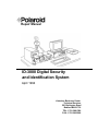
ID-3000 Digital Security
and Identification System
April 1994
Americas Business Center
Technical Services
201 Burlington Road
Bedford MA 01730
TEL: 1.781.386.5309
FAX: 1.781.386.5988
This page intentionally blank.
Polaroid ID3000 Service Manual
Contents
ID-3000 SYSTEM SERVICE MANUAL
CONTENTS
SECTION 1
GENERAL DESCRIPTION OF SYSTEM
SECTION 2
SYSTEM INSTALLATION
SECTION 3
DIAGNOSTICS/TROUBLESHOOTING
SECTION 4
CALIBRATION PROCEDURES
SECTION 5
PARTS REPLACEMENT
APPENDIX
This page intentionally blank.
Polaroid ID3000 Service Manual
Description
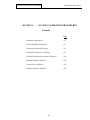
SECTION 1 - DESCRIPTION
Contents
Page
System Overview
1-3
System Hardware Components
1-5
System Functions:
Make a new ID card
Capture Portrait & Signature
Enter Applicant Data Only
Verify Applicant
Reissue ID card
Adjust System
1-7
1-7
1-8
1-8
1-8
1-8
1-8
Workstation Computer
1-9
Board Descriptions
1-10
Computer Keyboard
1-10
Color Monitor
1-11
Color Portrait Camera
1-12
Portrait Lighting Strobe Unit
1-12
Signature Scanner
1-13
Color Film Recorder (CFR) & Camera Back
1-14
Thermal Color Printer
1-15
Digital Scanner
1-16
Die Cutters
1-17
Laminators
1-17
Surge Protector/Power Strip
1-18
1-1
Polaroid ID3000 Service Manual
Description
This page intentionally blank.
1-2
Polaroid ID3000 Service Manual
Description
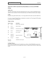
SECTION 1 — ID-3000 SYSTEM DESCRIPTION
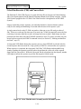
ID-3000 System Overview
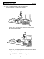
The Polaroid ID-3000 System (Figure 1-1) produces highly secure, color-portrait photoidentification cards, and electronically stores text, portraits and other ID images for each
applicant. ID cards consist of several elements, and may include: information about the applicant, his or her portrait, signature, fingerprints and card format elements.
There are presently two versions of the ID-3000 System, differing only in the output device
used to produce the photo ID card. The ID-3000F System has a CI-5000 Color Film Recorder which produces the ID card on Polaroid instant color film. The ID-3000T System has
a TX-1500 Color Thermal Printer which produces a full- color ID card on heat-sensitive
paper.
The system can operate as part of a network (LAN, WAN, Mainframe), linked to a host
computer, or it can function as a stand-alone system. The system electronically captures the
applicant’s video portrait and signature and stores them in memory, along with text data about
the applicant and identification card formatting data. The data may be stored in either a host
computer or in a local disk drive in the System PC.
After information about the applicant has been stored, it can be rapidly retrieved and displayed on the system monitors, for verification, updating or adding missing information.
System software combines the applicant data and portrait with specific codes, colors or
designs, to produce a custom ID card.
The ID3000 System can be integrated with the CS500i Polaroid Color Scanner, Magstripe
Encoder, Bar Code Label Printers, and Still Video Camera systems.
1-3
Polaroid ID3000 Service Manual
Description
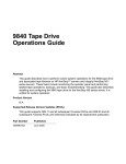
Note: Leave 12" or more between the CI-5000 Color Film Recorder
and the VGA Monitor, to prevent electrical interference.
ID-3000F with CI-5000 Film Recorder, CS500i Color Scanner (optional)
and Signature Scanner (optional)
ID-3000T with TX-1500 Thermal Recorder, CS500i Color Scanner (optional)
and Signature Scanner (optional)
Figure 1-1 ID-3000F and 3000T System configurations
1-4
Polaroid ID3000 Service Manual
Description
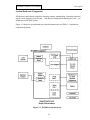
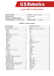
System Hardware Components
All hardware and software needed for acquiring, storing, manipulating, formatting and printing the visual elements of the ID card — and then die-cutting and laminating the card — are
included in an ID-3000 System.
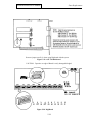
Figure 1-2 shows the system hardware in block diagram form, and Table 1-1 explains the
component functions.
Figure 1-2 ID-3000 System hardware
1-5
Polaroid ID3000 Service Manual
Description
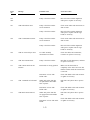
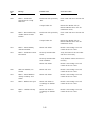
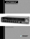
Table 1-1 ID-3000 System hardware component functions
Workstation
Computer
Controls input & output units, stores portraits, data, signatures, and card
formats; captures, manipulates and combines portraits, signatures & data
with card format, for printing by the color film recorder (CI5000) or
thermal printer TX1500. Can be configured to exchange data with a
mainframe host.
Keyboard
Enters text data; communicates with computer.
13" Color
Monitor
Displays menus, prompts, messages & applicant data. Also displays the
applicant's portrait (as captured by the portrait camera or as stored in
the system), and any other identification images captured or stored by
the system.
Color
Camera
Converts the applicant image into a video signal for use in creating the ID
Portrait card and for electronic storage. Includes an electronic flash unit for
Camera consistently color- balanced high-quality portraits.
Signature
Scanner
Scans the applicant’s signature from the signature card for storage, monitor
display and printing on ID card.
Color Film
Recorder
(CI5000) and
Camera back
(ID3000
System only)
Exposes portrait, signature, data and format elements (company name,
logo, etc.) on Polaroid instant film, in vertical or horizontal format.
Contains power supply and connections for monitor, portrait camera and
electronic flash. Camera Back attached to CI5000 holds film pack in
position, and initiates development when film is pulled through rollers.
Permits one or two cards per film sheet.
Color
Prints full-color ID card image (including portrait and other images), ready
Thermal
for die cutting and laminating. Printer contains a power
supply and
Printer
connections for the display, portrait camera and electronic flash.
TX1500
(ID3000 T
Systems only)
Die Cutter
Die cuts developed ID cards from sheet of Polaroid instant film. One card/
film sheet and two cards/film sheet models available.
Laminator
Heat-seals die-cut ID card in a tough, tamper-resistant, long-life plastic
enclosure.
Surge
Protector
Protects System from AC power line surges.
1-6
Polaroid ID3000 Service Manual
Description
ID-3000 System Functions
Simple operation is provided by monitor display of menu choices and prompts, to which the
operator responds by typing appropriate answers with the keyboard. Automated diagnostics
help speed identification and correction of operator errors or system malfunctions.
After log-in by typing a username and password and selecting Issue or Verify Badges from the
Main Menu, the system asks the operator to set the film counter by entering the film tab
number.
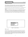
When these two operations have been done correctly, the system then displays the Operator’s
Menu (Figure 1-3). The six choices offered by this menu are explained below. Menu and
screen selections are easily made by either highlighting the choice or typing the first letter of
the choice; help screens for most menus and screens further simplify and speed system use.
(See the ID-3000 System Operator’s Guide for detailed explanations of all operating steps.)
Figure 1-3 Operator’s Menu
Make a New ID
Guides the operator in issuing an ID card to an applicant who has not had a card made with
this system, or updating an applicant’s portrait, signature and data before issuing a replacement card. Steps involve capturing and storing the new portrait, signature and applicant data,
and producing an ID card. Film develops in 90 seconds (or thermal image is printed), and is
then die cut and laminated. Applicant’s portrait, signature and text data previously stored
remain in the system or host disk.
1-7
Polaroid ID3000 Service Manual
Description
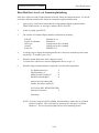
Capture Portrait and Signature
Permits capturing and storing the applicant’s portrait and signature so that an ID card can be
made at a later time.
Enter Applicant Data Only
Used for entering or updating applicant data only, without capturing a portrait or signature.
Verify Applicant
Permits recalling previously stored applicant data, portrait and signature for review.
Reissue ID Card
Permits reissuing an ID card using a portrait and signature previously stored, or, with Capture Portrait and Signature menu option, to issue a new ID card using previously stored
portrait, signature and data.
Adjust System
Allows changing the ID card tint; lightening or darkening the card or the portrait; changing
the film processing time. Adjust the Signature Scanner and Color Portrait Scanner when
available.
1-8
Polaroid ID3000 Service Manual
Description
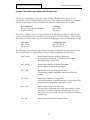
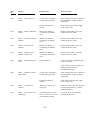
ID-3000 Workstation Computer
The System computer (Figure 1-4) controls the operation of all other ID-3000 System input
and output hardware, and with the keyboard and monitor, provides the means for communication between the system and the operator.
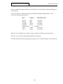
The computer in the ID-3000 workstation is a Hewlett-Packard Vectra Model QS/20 386*,
using the 32-bit Intel 80386 microprocessor. Principal features include:
8mb Simm RAM (on HP CPU Board)
1.2mb 5.25" floppy disk drive
SCSI hard disk drive and controller (48mb, 85mb, 120mb, 180mb, 240mb, 340mb or
760mb)
SCSI tape backup (150/250mb or 525mb)
Super VGA Adapter Card
Matrox Illuminator Board
Support Board
Data compression board (DSP)
Network interface - in systems configured for mainframe networks (optional)
Two serial ports and one parallel port are standard; four serial ports and one parallel
port are optional
*NOTE: Model currently supplied. The computer and other system hardware is
subject to change at any time.
Figure 1-4 ID-3000 HP Vectra QS/20 Workstation Computer
1-9
Polaroid ID3000 Service Manual
Description
Board Descriptions
Polaroid DSP Board — in conjunction with software algorithms, compresses images from
300 kbytes to and average of 8 kbytes.
AST I/O Board — provides two serial ports and one parallel port.
Matrox Illuminator Board — digitizes analog signal from the portrait video camera; sends
digital signal to the Color Film Recorder (CI5000) in ID-3000F System, or Thermal Printer in
the ID- 3000T System.
Super VGA Adapter Card — transfers data from the CPU to the color monitor.
SCSI and Floppy Controller Board — interface between the CPU and system drives and
components.
HP CPU Board — computer’s central processing unit. Interprets and executes instructions
by performing arithmetic operations, controlling instruction processing, and providing timing
signals and other housekeeping operations.
Polaroid Support Board — controls strobe firing, auto lens, and signature scanner (when
used).
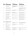
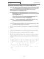
Computer Keyboard
The HP Vectra Enhanced Keyboard, for controlling the system through the computer and
inputting applicant data, has 101 keys arranged as shown in Figure 1-5. Keyboards are
supplied with the ID-3000 System for either U.S., French, German, Spanish, Japanese, U.K./
English, Italian or French Canadian languages, depending on the customer’s choice. (See the
HP Vectra QS Operator’s Manual, pages 10-9 to 10-14 for illustrations of these keyboards.)
.
Figure 1-5 HP Vectra Enhanced Keyboard
1-10
Polaroid ID3000 Service Manual
Description
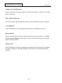
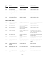
13" Color Monitor
The HP D1182 Video Graphics Color Display is a high-resolution color CRT display unit with
maximum screen resolution of 640 x 480. It offers minimum screen distortion and a 0.28mm
dot pitch, analog video input able to display an infinite number of colors, and anti- glare silica
screen coating. Power, brightness and contrast controls are located on the front panel.
Figure 1-6 13" Color Monitor
1-11
Polaroid ID3000 Service Manual
Description
Color Portrait Camera
The ID-3000 System camera (Figure 1-7), which captures the live portrait of the applicant, is
a JVC TK-87OU color video camera equipped with either a 16mm (standard) or 25mm
(optional) auto-iris lens.
The Camera has a solid-state CCD image pickup element capable of producing excellent print
quality free of latent images and distortion. Horizontal resolution is 330 TV lines. RGB
primary color filter system yields excellent color reproduction. Operating voltage is 12 VDC.
Figure 1-7 Color portrait video camera and strobe unit
Portrait Lighting
Lighting for the applicant’s face image is provided by a Vivitar Model 283 Strobe unit
mounted in a shoe on the top of the Camera and Strobe Bracket Assembly (Figure 1-7).
Strobe light output is triggered by the Support Board in the computer. Strobe operating
power is supplied by the power supply in the CI-5000 Assembly or TX-1500 Assembly.
1-12
Polaroid ID3000 Service Manual
Description
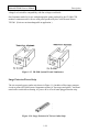
Signature Scanner
The optional Signature Scanner captures the applicant’s signature from a specially-designed
signature card.
The ID-3000 system prints the signature on the identification card for added security.
The ID-3000 system also stores the signature electronically for card reissue or verification.
.
.
.
Figure 1-8 Signature Scanner
1-13
Polaroid ID3000 Service Manual
Description
Color Film Recorder (CFR) and Camera Back
The Polaroid CI-5000 CFR (Figure 1-9) prints full-color ID card images on Polaroid instant
film, from digital signals from the Matrox Illuminator Board in the System computer. (An ID3000 System equipped with a CI-5000 Color Film Recorder is designated as an ID-3000F
System.)
Images contain the portrait, signature, text and other distinctive format elements, and are
ready for die-cutting and laminating 90 seconds after the start of the exposure cycle.
A single camera back on the CI-5000 can produce either one or two ID cards per sheet of
film. When two cards per film sheet are to be made, the CI-5000 electronically stores the first
card image in memory until the second card image has been recorded. Both images are then
printed on the film sheet when the EXPOSE command is used. (To print a card after only one
image has been exposed, the FORCE command is used; see Section 2, “Making an identification card”, step 15.)
A front-panel LED flashes during the exposure process, when EXPOSE is selected after the
second exposure has been made in a 2-up system (or FORCE is selected after one exposure).
When exposure is completed, the front-panel “Pull Film” LED flashes and an audible beep
sounds, signaling the operator to pull the white tab and then the yellow tab of the exposed
frame from the camera back. When the 90-second film development time has elapsed, another
LED lights to inform the operator to peel the film negative from the print.
Figure 1-9 Color Film Recorder Assembly used in ID-3000F System
1-14
Polaroid ID3000 Service Manual
Description
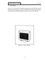
Thermal Color Printer
The Polaroid TX-1500 Color Thermal Printer (Figure 1-10) is a customer-selected output
alternative to the CI-5000 CFR described earlier. An ID-3000 System equipped with a TX1500 Printer is designated as an ID-3000T System.
The TX-1500 produces either one or two full-color ID card images on a single 4 x 5" (100 x
128mm) sheet. Print time is about 110 seconds after the frame button has been pressed. The
printing system is a dye diffusion thermal transfer process, which uses a three-color ink cartridge and paper supplied as a set.
Picture quality is characterized by 2.1 million available colors, 128 gray levels and 464 x 616
dots. On screen controls include color, tint, contrast and brightness.
.
Figure 1-10 TX-1500 Color Thermal Printer used in ID-3000T System
1-15
Polaroid ID3000 Service Manual
Description
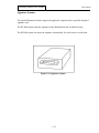
Digital Color Scanner (optional)
The Digital Color Scanner is a high-speed computer peripheral which captures and digitizes
images from color and black & white photographs or other reflective graphics. It accepts
documents up to 4.12 by 8.50 inches. Maximum scanning area is 4 by 6 inches.
The scanner uses state-of-the-art charge coupled (CCD) technology and scans at very high
speeds.
Figure 1-11 Digital Color Scanner
1-16
Polaroid ID3000 Service Manual
Description
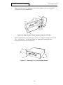
Die Cutter
Die Cutters for the ID-3000 System smoothly and accurately cut the ID card(s) to proper size,
from the Polaroid photographic or thermal print. They operate manually when the handle is
pulled forward.
Two versions are available:
1-Up CR-80 (2-1/8" x 3-3/8" ID cards)
2-Up std. for CR-60 (1-3/4" x 2-1/4" ID cards)
1-Up or 2-Up CR-79 (1-7/8" x 3-1/8" ID cards)
Figure 1-12 ID-3000 System Die Cutters
Laminator
The Laminator (Figure 1-13) for ID-3000 Systems heat-seals the die- cut ID card into a
protective, durable plastic pouch.
Features of this self-contained, electrically-operator Laminator include automatic roller start
when an optical switch senses a card has been inserted into the Laminator, and automatic AC
1-17
Polaroid ID3000 Service Manual
Description
voltage level switch for compatibility with line voltages world-wide.
One Laminator model is for use with photographic prints produced by the CI-5000 CFR,
another Laminator model is for use with prints produced by the Color Thermal Printer
TX1500. (Units are not interchangeable in application.)
Figure 1-13 ID-3000 System ID card Laminators
Surge Protector/Power Strip
The six-receptacle power outlet strip shown in Figure 1-14 includes a filter/surge protector
circuit to protect ID-3000 System components against AC line surges and spikes. An illuminated rocker switch allows turning AC power on or off to all units plugged into the strip.
Figure 1-14 Surge Protector/AC Power Outlet Strip
1-18
Polaroid ID3000 Service Manual
System Installation
SECTION 2 - SYSTEM INSTALLATION
Contents
Page
Software, Tools & Equipment required
2-3
Major Installation Steps
2-3
Powering Up the System
2-12
Loading Paper and Ink
2-13
Care & Handling of Paper, Ink and Prints
2-14
Functional Check of the System
Setting Film Counter
Making an Identification Card
Storing a Portrait and Signature
Entering Applicant Data Only
Verifying Applicant Data
Reissuing an Identification Card
Adjusting the Card for the ID3000 Film System
Adjusting the Color Card for the ID3000 Thermal System
Adjusting the Color Portrait Camera
Adjusting the Signature Scanner
2-16
2-17
2-18
2-25
2-27
2-29
2-30
2-34
2-39
2-44
2-48
Portrait Scanner Adjustment
Calibrating the Scanner
Adjusting the Portrait Capture Area
Restoring the Factory-Set Capture Area
Changing the Film Type Setting
2-51
2-51
2-52
2-55
2-57
Exiting from the System
2-59
Checking Laminator Temperature
2-60
2-1
Polaroid ID3000 Service Manual
System Installation
This page intentionally blank.
2-2
Polaroid ID3000 Service Manual
System Installation
SECTION 2 — ID-3000 SYSTEM INSTALLATION
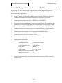
Software, Tools and Equipment
The following equipment and materials are needed for ID-3000 System installation:
Multimeter
Field Service Toolkit
(see Section 4)
Installation Toolkit
ID-3000 Installation and
Service Manual
Calibration and Diagnostic Diskettes
(may be included within the ID3000
Tools Diskette)
Color Calibration Card #1B2195A
Grounding strap
Major Installation Steps
Installation consists of the following procedures performed in sequence:
1.
Laying out the installation site
2.
Unpacking and assembling the system
3.
Checking computer internal connections
4.
Installing cables
5.
Powering up the system, log-in and main menu display
6.
Functionally checking system performance:
Setting film counter
Making an identification card
Storing a portrait and signature
Entering applicant data only
Verifying applicant data
Reissuing an identification card
Adjusting the system
Exiting from the system
7.
Checking Laminator Temperature
2-3
Polaroid ID3000 Service Manual
System Installation
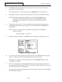
Laying out the installation site
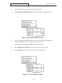
Sufficient space must be available to allow the layout shown in Figure 2-1. (The installation technician should call ahead to verify space availability before proceeding to the site.) Particularly important is the camera-to-subject distance.
NOTE: For ID-3000F System, place CI-5000 Color Film Recorder Assembly at least 12" away
from VGA Monitor to prevent electrical interference.
Figure 2-1 Typical ID-3000 layout
2-4
Polaroid ID3000 Service Manual
System Installation
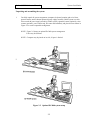
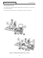
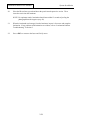
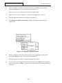
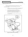
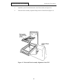
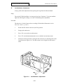
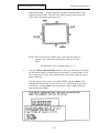
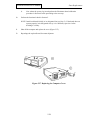
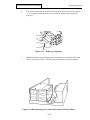
Unpacking and assembling the system
1.
Carefully unpack all system components (computer, keyboard, monitor and swivel base,
portrait camera, strobe, thermal printer & power supply assembly (3000T system) or color
film recorder & power supply assembly (3000F system), signature scanner (optional), color
scanner (optional), power outlet strip, die cutter and laminator), and place them as shown in
Figure 2-2 or some comparable arrangement.
NOTE: Figure 2-2 shows an optimal ID-3000 system arrangement.
Yours may be different.
NOTE: Computer may be placed on its side, if space is limited.
I
Figure 2-2 Optimal ID-3000 system setup
2-5
Polaroid ID3000 Service Manual
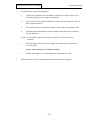
2.
System Installation
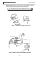
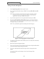
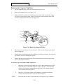
Mount the monitor on the swivel base (see Figure 2-3): invert the monitor, engage front
edge of base under tabs on monitor, snap pin into hole at back of base.
Note: The latest monitor does not require mounting to the swivel base.
Figure 2-3 Mounting Color Monitor on Swivel Base
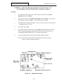
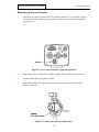
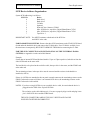
Figure 2-4 Mounting Camera, Strobe and Bracket Assembly
2-6
Polaroid ID3000 Service Manual
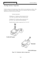
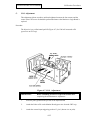
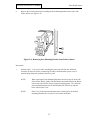
3.
System Installation
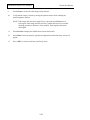
Assemble the color portrait camera and strobe as follows (see Figure 2-4): slip camera/
strobe bracket over camera; attach bracket to microfluid tripod head by tightening tripod
screw; attach strobe to shoe on top of bracket; connect the five cables in the cable
assembly to the appropriate connectors on lens barrel, strobe and back of camera. Hold
the camera pole close to the output unit (film recorder or thermal) and insert the two thumb
screws and hand-tighten them.
NOTE: Before inserting the power supply plug into the strobe, be sure the plug locking tab
is fully retracted (turn the thumbwheel in the plug to the left as far as it will go).
Then open the strobe battery compartment and insert the power plug. Press down on
the plug and rotate the thumbwheel in the plug to the right as far as it will go, to
engage the plug locking tab with the plug socket.
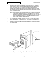
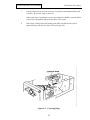
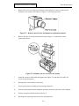
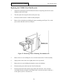
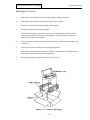
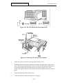
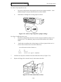
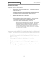
4.
For ID-3000F System, attach the Camera Back to the front of the Color Film Recorder &
Power Supply Assembly, as shown in Figure 2-5. Finger-tighten the two thumbscrews.
5.
Place the Die Cutter on top of the Laminator and plug the power cord from the Laminator
into the Power Strip.
Figure 2-5 Attaching the Camera Back to the Film Recorder
2-7
Polaroid ID3000 Service Manual
System Installation
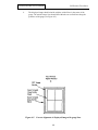
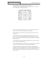
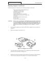
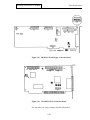
Checking computer internal connections
Computer circuit boards and cables can loosen during shipping and cause malfunctions. Check them
as follows before proceeding further with installation:
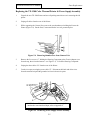
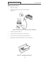
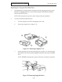
1.
Remove the computer cover (Figure 2-6).
2.
Visually inspect all computer components to assure they are fully seated in their slots,
sockets and board guides, and that all cable connections are secure, especially the alpha
cable that connects between the matrox board and the VGA board.
3.
Inspect the battery wire and its connection to the board, and tighten if necessary.
4.
Replace the computer cover.
.
Figure 2-6 Removing the Computer Cover
2-8
Polaroid ID3000 Service Manual
System Installation
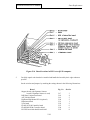
Installing cables
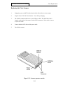
1.
Lay out the cables, checking them against the lists below and Figure 2-7 (ID-3000F
system) or Figure 2-8 (ID-3000T system), to assure that you have a complete set.
2.
Connect all cables according to either Figure 2-7 or 2-8.
Caution: Do not connect the surge protector/power strip power cable to AC
power until all other connections are secure.
Warning: To prevent connector damage, use the following procedure:
3.
a.
Before attempting to connect the cable, back out the connector screws until
they are flush with the face of the connector.
b.
Gently rock the cable connector onto its mating connector on the console.
c.
Tighten the connector screws.
Install tie-wraps as needed to achieve a neat cable arrangement.
ID-3000F System Cables
ID-3000T System Cables
Digi Cable (optional)
SCSI Cable
Computer Power Cable
Keyboard Cable
Monitor Power Cable
Monitor Video Cable
Support Board Cable
Capture Board Cable
Camera/Strobe Cable Assy
Computer/Modem Cable
CI-5000 Power Cable
Signature Scanner Cable (optional)
CS500I Color Scanner SCSI Cable (optional)
Color Scanner Power Cable (optional)
CI5000 SCSI Terminator (optional)
Digi Cable (optional)
Computer Power Cable
Keyboard Cable
Monitor Power Cable
Monitor Video Cable
Support Board Cable
Capture Board (In) Cable
Capture Board (Out) Cable
Camera/Strobe Cable Assy
Computer/Modem Cable
TX-1500 Power Cable
Signature Scanner Cable (optional)
CS500I Color Scanner SCSI Cable (optional)
Color Scanner Power Cable (optional)
CS500I Terminator (optional)
2-9
Polaroid ID3000 Service Manual
System Installation
Figure 2-7 ID-3000F System Cable Connections
2-10
Polaroid ID3000 Service Manual
System Installation
Figure 2-8 ID-3000T System Cable Connections
2-11
Polaroid ID3000 Service Manual
System Installation
Powering Up the System
Turn on all ID-3000 components using their individual power switches (Figure 2-9), except for the
power strip/surge protector.
Now plug the power strip cable into an AC receptacle and turn on the power strip switch.
Figure 2-9 ID-3000 System Component Power Switches
2-12
Polaroid ID3000 Service Manual
System Installation
Loading Paper and Ink in Thermal Color Printer
A paper/ink set consists of a packet of paper and an easy-to-load ink cartridge. Ink cartridges contain
enough ink for the number of paper sheets in the set.
Do not interchange paper and ink cartridges from different sets, or add print paper from a new set
without changing the ink cartridge. Doing so may cause a paper jam and/or a poor quality image.
Each paper set (C1500) include 100 sheets of print paper and a high density ink cartridge which
produces full color prints.
Loading Paper
Follow instructions precisely, as
incorrect loading can cause paper
jams and/or defective printing.
Important: Before using the printer
for the first time, clean the paper
supply belt as described on page 25.
This will eliminate any dust or small
particles accumulated during shipping
which could mar print quality.
1. Open the cassette door by pulling the
PULL-OPEN tab (a).
2. Swing out the paper cassette (b).
3. Tilt down the front edge of the paper
cassette (c).
4. Make sure the partition in the cassette
is in the vertical position (d).
5. Insert the paper into the cassette with
the marked side facing up. The paper
must not be stacked above the green
mark on the inside of the cassette.
Overloading the cassette will cause a
paper jam.
6. Tilt the front edge of the cassette to its
original position (e).
7. Swing the paper cassette back into the
unit. Close the paper cassette door.
Note: The paper light will blink when the printer runs out of paper, if the paper is folded, creased or upside
down, if the wrong paper is used, or if the paper cassette is not pushed all the way in.
2-13
Polaroid ID3000 Service Manual
System Installation
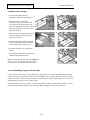
Loading an ink cartridge
1. Open the ink cartridge door by
pushing the OPEN/CLOSE button (a).
2. Move the ink lever to the down
position (b), being careful not to catch
your fingers in the spring. Remove the
protective storage insert from the cartridge
housing (but keep it for use when transporting the printer).
3. Check the tension of the film (ink paper)
in the ink cartridge. If the film is loose,
tighten it as shown (c).
4. Slide the ink cartridge into the compartment (d), holding the knob on the front
of the cassette. Push it all the way in.
5. Return the ink lever to its original position (e).
6. Close the ink cartridge door, and press the
OPEN/CLOSE button to latch it.
Note: The ink light will blink if the film (ink paper)
runs out, if it is cut, if the ink cartridge is not inserted correctly, or if the ink door is not closed.
Care and handling of paper, ink and prints
For best results, fan the entire packet of film before loading. However, do not touch the printing (unmarked)
surface of the paper or allow these surfaces to touch each other. Never use paper that has become wet, folded,
scratched, or creased. Protect the paper from dirt or dust. Do not use a piece of print paper twice. Do not leave
finished prints face down on a PCV plastic surface.
Store paper/ink sets in a cool, dry place. Avoid storing in direct sunlight. The ink cartridge cannot be reused.
Avoid touching the film (ink paper) in the cartridge. When loading, be sure this film is not loose.
2-14
Polaroid ID3000 Service Manual
System Installation
Log-in and main menu display
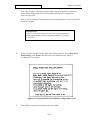
After powering up, allow five minutes for system warmup. During this time the monitor will display
a series of messages as the software is automatically loaded.
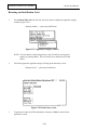
After the software has been loaded, the ID-3000 log-in screen will appear.
At the Username prompt, type CPS and press <Enter>.
At the Password prompt, type Polaroid or the System ID number and press <F10>. The System ID
number can be found on the side of the color portrait camera, the back of the film recorder assembly
or thermal printer assembly, and on the computer.
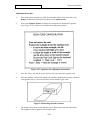
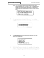
Wait for the Main Menu to appear (Figure 2-10). If the main menu fails to appear within a minute of
startup, turn the system off and then on again and repeat the log-in procedure. If the main menu still
fails to appear, refer to Section 3 of this Manual — On-Site Diagnostic Procedures.
.
Figure 2-10 ID-3000 main menu
2-15
Polaroid ID3000 Service Manual
System Installation
Functional Check of the System
To assure that the ID-3000 hardware and software are operating properly, the functional
check consists of:
-
Capturing new data, a portrait and a signature*, then using them to make an identification
card
-
Storing a portrait and signature
-
Entering applicant data only
-
Verifying applicant portrait, signature and data already stored in the system
-
Making an identification card from portrait, signature and data previously stored in the
system
-
Repeating the previous two steps, using a different applicant ID number.
*NOTE: Not all ID-3000 systems use a signature on the ID card.
Your ID card may not include a signature.
If problems are encountered in any of these operations, refer to the on-site diagnostic procedures in
Section 3 of this Manual.
2-16
Polaroid ID3000 Service Manual
System Installation
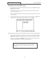
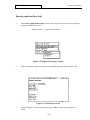
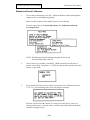
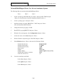
Setting Film Counter (ID-3000F System)
1.
After logging in and with main menu displayed (see Figure 2-10), select Issue or Verify
Badges and press <Enter>.
An ID-3000F System with a CI-5000 Color Film Recorder will then display a film tab
selection screen (Figure 2-11).
Insert a fresh pack of T-2000 film in the camera back and pull the black tab all the way out
of the camera back.
2.
Type the number printed on the white tab sticking out of the film holder (or highlight that
number on the screen, using the up or down arrow keys). Press <Enter>.
Figure 2-11 Screen for setting system film counter
Synchronizing the color thermal printer (ID-3000T System) when using non-interlaced input only.
1.
After logging in and with main menu displayed (see Figure 2-10), select Issue or Verify
Badges and press <Enter>. Check to make sure the Color Thermal Printer is turned ON.
When you select Issue or Verify Badges, the Issue and Verify menu will appear (with an
ID-3000T System which has a TX-1500 Color Thermal Printer).
Important note:
Figure 2-12 has been removed because it is no longer applicable;
all subsequent Figures remain as originally numbered, i.e. Figure
2-13 is next.
2-17
Polaroid ID3000 Service Manual
System Installation
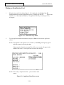
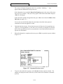
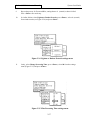
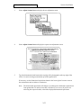
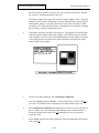
Making an Identification Card
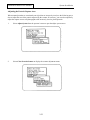
1.
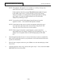
When the Issue and Verify Menu (Figure 2-13) is displayed, select Make a New ID
(highlight that line using the up/down arrow keys, or simply type the first
letter of the
selection - m or M) and press <Enter>). The applicant data entry screen (Figure 2-14)
will appear.
Figure 2-13 Issue and Verify menu
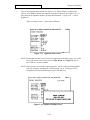
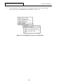
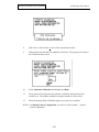
2.
Type an applicant identification number, then press <F10> to search for the applicant’s
record.
NOTE: The applicant’s data appears if it is available. (A “working” message may appear
while the system is retrieving the data.)
If data cannot be found, the message This will be a new record will appear in the
middle of the screen. Use the space bar to remove this message.
NOTE: This is only a sample data field — yours will have other
criteria.
Figure 2-14 Applicant Data Entry screen
2-18
Polaroid ID3000 Service Manual
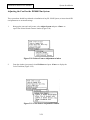
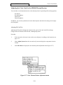
3.
System Installation
Type in the requested applicant data (see Figure 2-15). When all data is complete and
correct, press <F10> to display the signature message (if required). See Figure 2-16. (If
the system has no Signature Scanner, the Input Portrait Menu — Figure 2-19 — will be
displayed.)
(This is a sample screen — yours may be different)
Figure 2-15 Applicant data entries
NOTE: If more than one data screen is used for an applicant (indicated by page 1 of x in the
lower right corner of the screen), use the <Page Down> and <Page Up> keys to
move from one screen to another.
NOTE: If the message List element is required appears, you have entered an unacceptable
value (for example, entering m in a field requiring y or n). To display a list of
acceptable values for the field displayed, press the <F2> key.
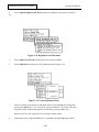
Figure 2-16 Signature prompt screen
2-19
Polaroid ID3000 Service Manual
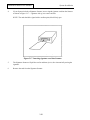
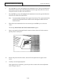
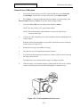
4.
System Installation
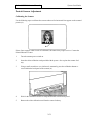
If your System includes a Signature Scanner, insert a signed signature card into the Scanner
as shown in Figure 2-17 — signature side up, cut-corner end first.
NOTE: The card should be signed with a medium point, black felt tip pen.
Figure 2-17 Inserting signature card into Scanner
5.
The Signature Scanner will pull the card in and then eject it, after electronically storing the
signature.
6.
Remove the card from the Signature Scanner.
2-20
Polaroid ID3000 Service Manual
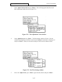
7.
System Installation
The system will now display the Input Portrait Menu (Figure 2-18).
NOTE: If no image appears on the Monitor, adjust the brightness control on the
Monitor or refer to Portrait Camera Adjustment on page 38 of this Section.
Figure 2-18 Input Portrait menu
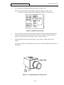
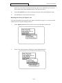
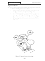
8.
Seat a person in the portrait chair and adjust the portrait camera (using the handle attached
to the camera stand) for proper framing in the monitor. (If necessary, adjust the subject’s
head size in the portrait by changing the camera- to-subject distance.)
9.
Adjust the portrait camera focus ring (Figure 2-19) to achieve a sharp portrait on the
monitor.
If the subject cannot be focused sharply, refer to camera focusing calibration in Section 4 of
this Manual.
Figure 2-19 Adjusting portrait camera focus
2-21
Polaroid ID3000 Service Manual
10.
System Installation
Select Freeze from the Input Portrait menu (Figure 2-18), to freeze the video image on
the monitor. The strobe will fire.
(If the applicant has a very dark complexion, select Brighten before selecting Freeze.)
11.
Verify that the image is frozen by moving the portrait camera while watching the monitor.
NOTE: If the image does not freeze when Freeze is selected, select Freeze once or
twice again. If the image still fails to freeze, go to the Freeze/Live trouble
shooting procedure in Section 3 of this manual. Then begin the functional
check again.
12.
Check the “frozen” portrait. If it is not acceptable, select Live, repose the applicant and
select Freeze again (let the strobe recharge for eleven seconds before selecting Freeze a
second time.)
NOTE: If you try to fire the strobe a second time before it has fully recharged, this
message will appear:
Strobe recharging — please wait
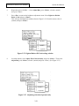
13.
When the portrait is acceptable, select Done to open the Exposure window (Figure 2-20).
Figure 2-20 Exposure window
14.
If you wish to preview the card before exposing the film, select Preview from the exposure
window. (Vertical cards will be turned horizontal on the monitor screen.)
If the portrait is not properly centered on the ID card, select Recapture and repeat steps
12 through 14 as needed.
15.
With a 2-up configuration, selecting Expose after the first exposure has been made sends
the image to the film recorder to be stored — actual exposure of the film does not occur until
the card is made, after the second exposure.
If you wish to print the image when only one has been made on a 2-up system, select Force
from the Exposure window.
2-22
Polaroid ID3000 Service Manual
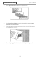
16.
System Installation
When the Output Unit beeps and the front panel LED flashes, pull the white tab and then
the exposed frame (yellow tab) out of the camera back.
NOTE: If you try to produce a film exposure after all frames in the film pack have
been used, the system will display the message shown in Figure 2-21:
Figure 2-21 Screen instruction to insert new film pack
CAUTION:
The instant film process uses a caustic jelly safely packaged in
sealed containers within the film pack. If you accidentally get this jelly on your
skin, wipe it off immediately. To avoid an alkali burn, wash the area with
plenty of water as soon as possible. Keep the jelly away from eyes and
mouth. Keep the discarded materials out of the reach of children and animals, and
out of contact with clothing and furniture. Discarded materials still contain some
jelly.
17.
Peel the negative from the print and inspect the photograph for image quality. If the
photograph is unsatisfactory, refer to “Image Quality Troubleshooting” in Section 3.
18.
Insert the picture into the die cutter. Move the card side to side as needed to align the
image with one of the die cutter openings and assure that the image will have no black
borders when the card is trimmed. If adjustments need to be made, see Camera Offset
Diagnostics in Section 3 of this Manual.
Note: Step 16 through 18 apply to the ID3000F system only; the ID3000T system produces color thermal ID cards directly.
19.
When the image is aligned in the die cutter, pull the handle down. Remove the trimmed
card and discard the waste.
2-23
Polaroid ID3000 Service Manual
20.
System Installation
Place the ID card into a pouch and insert the pouch into the protective carrier. Then
insert the carrier into the laminator.
NOTE: For optimum results, lamination should start within 15 seconds of peeling the
photograph from the negative (step 18).
21.
When the laminated card emerges from the laminator, inspect it for secure and complete
lamination. If any problems with lamination are evident, refer to “Lamination Problem
Troubleshooting” in Section 3.
22.
Press <ESC> to return to the Issue and Verify menu.
2-24
Polaroid ID3000 Service Manual
System Installation
Storing a Portrait and Signature
1.
Select Capture Images Only from the operator’s menu.
2.
Type an applicant card number, then press <F10>. The message This will be a new ID
will appear.
NOTE: If the system already contains data for this applicant card number, the data
will appear on the screen for verification or editing. If this information
appears and is correct, press <F10> and omit step 3.
3.
Type in the data requested at the various applicant data fields, then press <F10>.
4.
The message Insert Signature Card Into Slot will appear. If your System includes a
Signature Scanner, insert a signed signature card into the Scanner as shown in Figure 222, signature sideup, cut-corner end first.
NOTE: The card should be signed with a medium point, black felt tip pen.
Figure 2-22 Inserting signature card into Scanner
5.
The Signature Scanner pulls the card in and then ejects it in 5 seconds, after electronically
storing the signature.
6.
Remove the card from the Signature Scanner.
7.
Seat a person in the portrait chair and adjust the portrait camera (using the handle attached
to the camera stand) for proper framing in the monitor.
8.
If necessary, adjust the portrait camera focus ring to achieve a sharp portrait on the
monitor.
If the portrait still does not focus sharply, refer to Camera Focusing Calibra
tion in Section 4.
2-25
Polaroid ID3000 Service Manual
System Installation
9.
Select Freeze to freeze the video image on the monitor.
10.
Verify that the image is frozen by moving the portrait camera while watching the
portrait/signature monitor.
NOTE: If the image does not freeze when Freeze is pressed, press Freeze once or
twice again. If the image still fails to freeze, perform the Freeze/Live trouble
shooting procedure in Section 3 of this manual. Then begin the functional
check again.
11.
Select Preview to display the identification card on the monitor.
12.
Select Done to store the portrait, signature and applicant A blank data entry screen will
appear.
13.
Press <ESC> to return to the Issue and Verify menu.
2-26
Polaroid ID3000 Service Manual
System Installation
Entering Applicant Data Only
1.
Select Enter Applicant Data Only from the Issue and Verify menu to open the applicant
category window (Figure 2-23).
(Sample window — yours may be different)
Figure 2-23 Applicant Category window
2.
Select an applicant category to open the corresponding data entry screen (Figure 2-24).
.
..
Figure 2-24 Data Entry screen
3.
Type the applicant’s ID card number, then press <F10> to search for the applicant’s
record.
2-27
Polaroid ID3000 Service Manual
System Installation
NOTE: The applicant’s data appears if it is available. (A “working” message may
appear while the system is retrieving the data.)
If data cannot be found, the message This will be a new record will appear
in the middle of the screen. Use the space bar to remove this message.
Then you can either (1) re-attempt entry of the ID card number by starting
step 3 again, or (2) enter new applicant data for the ID card number
displayed by continuing at step 4.
NOTE: You can also use the ID-3000 enhanced search feature to locate the
applicant’s record — refer to the ID-3000 Operator’s Manual.
NOTE: If more than one data screen is used for an applicant (indicated by page 1
of x in the lower right corner of the screen), use the <Page Down> and
<Page Up> keys to move from one screen to another.
NOTE: If the message List element is required appears, you have entered an
unacceptable value (for example, entering m in a field requiring y or n). To
display a list of acceptable values for the field displayed, press the <F2>
key.
4.
Check the applicant data to be sure it is correct. If necessary to correct or complete the
data, use the up and down arrow keys to position the cursor at the desired location and
type the new information.
5.
When all data is complete and correct, press <F10> to save the data and display a blank
entry screen.
6.
If another applicant’s data is to be entered, start again at step 3. If not, return to the Issue
and Verify menu by pressing <Esc>.
2-28
Polaroid ID3000 Service Manual
System Installation
Verifying Applicant Data
1.
Select Verify Applicant from the Issue and Verify menu to display the applicant category
window.
2.
Select the appropriate applicant category to bring up the data entry screen.
3.
Type the applicant’s ID card number used to make the identification card in the previous
section (the corresponding data should be stored in the system), then press <F10>. The
applicant data should appear on the monitor, along with the applicant’s portrait. (Waiting . . .
may appear while the information is being retrieved.)
If the information is not available, No Matching Records Found appears in the center of the
screen. Try a second time to retrieve the stored data, by repeating step 3. If the message
No Matching Records Found appears again, press the space bar to remove the message.
Then you can enter another ID card number and press <F10> to search again.
You can also use the ID-3000 enhanced search feature described in the operator’s
instructions to locate the applicant’s record.
4.
Check the data, portrait and signature for accuracy and image quality. If more than one
screen of data exists for an applicant, use <Page Up> and <Page Down> to view data.
NOTE: If any of the three elements does not display properly (data, portrait or
signature), press <Esc> to return to the data entry screen and repeat steps
3 and 4. If the displayed items are still unsatisfactory, perform the
appropriate troubleshooting procedure in Section 3 of this manual.
5.
Any attempt to edit the data displayed is impossible.
6.
Verify another applicant by typing a new applicant ID card number (a number not
previously entered or stored in the system), then press <F10>. The message No matching
records were found. Press any key to continue should appear.
7.
Press <Esc> to return to the Issue and Verify menu.
2-29
Polaroid ID3000 Service Manual
System Installation
Reissuing an Identification Card
1.
Select Reissue ID Card from the issue and verify menu to display the applicant category
window (Figure 2-25).
(Sample window — yours may be different)
Figure 2-25 Applicant Category window
NOTE: You can stop the card-issuing process at any time before card exposure
begins, by pressing <Esc>. This will return you to the Reissue ID Card
choice.
2.
Select the appropriate applicant category to bring up the data entry screen:
(Sample screen — yours may be different)
Figure 2-26 Data Entry screen
3.
Type the previously stored ID card number, then press <F10> to search for the
applicant’s record.
2-30
Polaroid ID3000 Service Manual
System Installation
The screen will display the applicant data if it is available. (Working . . . may
appear while the information is being retrieved.)
If the information is not available, Record Not Found appears in the center of the screen.
Press any key to continue. Then you can try again to enter the ID card number and press
<F10> to search again.
If this still fails to produce the applicant data, press <Esc> twice and select Make a New
ID Card. (See page 2-13.)
You can also use the ID-3000 enhanced search feature described in the operator’s
instructions to locate the applicant’s record.
4.
Check the data for accuracy. If more than one screen of data exists for an applicant, use
<Page Up> and <Page Down> to view data. If it is necessary to complete or correct the
data, use the up and down arrow keys to position the cursor at the desired location and
type the new information.
5.
When all information is complete and correct, press <F10> to open the exposure window
(Figure 2-27):
Figure 2-27 Exposure/Preview screen
6.
To preview the card before exposure, select Preview from the exposure window. The
monitor will display the card in full color (vertical cards will be rotated to a horizontal
position).
2-31
Polaroid ID3000 Service Manual
7.
System Installation
With a 2-up system, selecting Expose the first time stores the ID in memory. Actual
exposure of the film occurs when Expose is selected for the second ID.
If you wish to print the image when only one has been made on a 2-up system, select
Force from the Exposure window.
When a blank data entry screen returns, the next ID card can be made.
NOTE: If no additional ID cards will be made immediately, press <Esc> twice to
return to the main menu. The Pull Film message will be displayed. Pull the
white and yellow tabs from the film holder to begin film processing.
8.
Repeat steps 3 and 4 to enter or correct another applicant’s data.
9.
Continue with steps 5, 6 & 7 to make the second ID card. After the second ID card is
exposed, the message Pull the Film on the Camera Back will appear. Pull the white and
yellow tabs before making another ID card.
10.
Press the blue button on the upper timer and when the green LED flashes and the timer
beeps, peel the photograph from the negative.
CAUTION: The instant film process uses a caustic jelly safely packaged in
sealed containers within the film pack. If you accidentally get this jelly on your
skin, wipe it off immediately. To avoid an alkali burn, wash the area with
plenty of water as soon as possible. Keep the jelly away from eyes and
mouth. Keep the discarded materials out of the reach of children and
animals, and out of contact with clothing and furniture. Discarded materials
still contain some jelly.
Note: Steps 9 and 10 apply only to the ID3000F system.
11.
Inspect the photograph for image quality. If the photograph is unsatisfactory, refer to
“Image Quality Problems” in the On-Site Diagnostic Procedures in Section 3.
12.
Insert the picture into the die cutter. Move the card side- to-side as needed to align the
image with one of the die cutter openings. If adjustments need to be made, see Camera
Offset Diagnostics in Section 3 of this Manual.
13.
When the image is aligned in the die cutter, pull the handle down. Remove the trimmed card
and discard the trimmed waste. Inspect the trimmed card for proper registration.
.
Place the ID card into a pouch and insert the pouch into the protective carrier. Then
insert the carrier into the laminator.
2-32
Polaroid ID3000 Service Manual
System Installation
NOTE: For optimum results, lamination should start within 15 seconds of peeling
the photograph from the negative.
15.
When the laminated card emerges from the laminator, inspect it for secure and complete
lamination. If any problems with lamination are evident, refer to “Lamination Problem
Troubleshooting” in Section 3.
16.
Press <Esc> to return to the operator’s menu.
2-33
Polaroid ID3000 Service Manual
System Installation
Adjusting the Card for the ID3000 Film System
These procedures should be performed at installation of any ID- 3000F System, to insure that all ID
card parameters are at normal settings.
1.
Bring up the issue and verify menu, select Adjust System and press <Enter> to
open Color Printer/Portrait Camera window (Figure 2-28).
Figure 2-28 Printer/Camera Adjustment window
2.
From the window just opened, select ID Printer and press <Enter> to display the
Color Tint Menu (Figure 2-29).
Figure 2-29 Color Printer Adjustment window
2-34
Polaroid ID3000 Service Manual
3.
System Installation
Select Adjust Tint Overall and press <Enter>. This will bring up the Red, Green and
Blue Adjustment window shown in Figure 2-30.
Figure 2-30 Tint Adjustment Colors window
4.
Select Adjust Red and press <Enter>. The Red settings window will open. Select 4
(normal) by using the up and down arrow keys to highlight 4 (normal), or simply type 4,
and press <Enter>. When you select the setting, the color selection window returns.
Figure 2-31 Red Tint Settings window
5.
Now select Adjust Green, press <Enter>, again select 4 (normal) and press <Enter>.
2-35
Polaroid ID3000 Service Manual
System Installation
6.
Repeat the process for Blue — select Adjust Blue, press <Enter>, select 4 (normal)
and press <Enter>.
7.
Press <Esc> to return to the brightness adjustment menu. Select Lighten or Darken
Entire Card and press <Enter>.
This will open the adjustment window shown in Figure 2-32. From this menu, select 4
(normal) and press <Enter>.
Figure 2-32 Lighten/Darken ID Card settings window
8.
In similar fashion, select Adjust Tint of Portrait Only, and press <Enter>. Then select
Adjust Red, press <Enter>, select 4 (normal) and press <Enter). (See Figure 2-33).
Figure 2-33 Adjusting color tint of portrait only
2-36
Polaroid ID3000 Service Manual
System Installation
9.
Repeat the process for Green and Blue, setting them to 4 (normal) as done for Red.
Press <Enter> after each step.
10.
In similar fashion, select Lighten or Darken Portrait, press <Enter>, select 4 (normal)
from window menu (see Figure 2-34) and press <Enter>.
Figure 2-34 Lighten or Darken Portrait settings menu
11.
Lastly, select Change Processing Time, press <Enter>, select 90 from the settings
menu (Figure 2-35) and press <Enter>.
Figure 2-35 Film Processing Time settings menu
2-37
Polaroid ID3000 Service Manual
12.
System Installation
To exit from this Color Printer System Settings program and save the normal settings
you have just made, select Done and press <Enter> (Figure 2-36).
Figure 2-36 Exiting and saving new settings menu
2-38
Polaroid ID3000 Service Manual
System Installation
Adjusting the Color Card for the ID3000 Thermal System
You can make several adjustments to the color thermal printer for optimizing ID card image quality:
ID card tint
ID card brightness
Portrait tint
Portrait brightness.
In addition, you can also synchronize the color thermal printer and check the settings on the output
unit front panel.
Adjusting ID Card Tint
Adjusting the ID card tint changes the amount of red, green or blue tint in the ID card image.
Changes affect all elements of the ID card, including the portrait.
Procedure
1.
If the issue and verify menu is not on the screen, display it according to the instructions on
page 2-12.
2.
Select Adjust System from the issue and verify menu to display the component selection
window.
3.
Select ID Printer to display the color thermal printer adjustment menu (Figure 2-37).
Figure 2-37 Color Thermal Printer adjustment menu
2-39
Polaroid ID3000 Service Manual
4.
38):
System Installation
Select Adjust Brightness and Tint to display the brightness and tint menu (Figure 2-
Figure 2-38 Brightness and Tint menu
5.
Select Adjust Tint Overall to display the color selection window.
6.
Select Adjust Red to display the color adjustment menu (Figure 2-39):
Figure 2-39 Color adjustment menu
7.
Select 4 (normal) by using the up and down arrow keys to highlight the setting, then
pressing the <Enter> key. Or if you prefer, type the number 4. (To return to the color
selection window without changing the current setting, press the <Esc> key.)
When you select a new setting, the color selection window returns.
8.
In the same way, set green and blue to 4 (normal), by repeating steps 6 and 7.
2-40
Polaroid ID3000 Service Manual
System Installation
9.
Press the <Esc> key to return to the brightness and tint menu.
10.
Select Lighten or Darken Entire Card to display the brightness adjustment menu.
Figure 2-40 Brightness adjustment menu
11.
Select 4 (normal) by using the up and down arrow keys to highlight the setting, then
pressing the <Enter> key. Or if you prefer, type the number 4.
When you select the setting, the brightness and tint menu returns.
12.
Select Adjust Tint of Portrait Only to display the color selection window.
13.
Select Adjust Red to display the color adjustment menu (Figure 2-41):
Figure 2-41 Color adjustment window
2-41
Polaroid ID3000 Service Manual
14.
System Installation
Select 4 (normal) by using the up and down arrow keys to highlight the setting, then
pressing the <Enter> key. Or if you prefer, type the number 4.
When you select a new setting, the color selection window returns.
15.
In the same way, set green and blue to 4 (normal) by repeating steps 13 and 14.
16.
Press the <Esc> key to return to the brightness and tint menu.
17.
Select Lighten or Darken Portrait Only to display the brightness adjustment menu
(Figure 2-42):
Figure 2-42 Brightness adjustment menu
18.
Select 4 (normal) by using the up and down arrow keys to highlight the setting, then
pressing the <Enter> key. Or if you prefer, type the number 4.
When you select a new setting, the brightness and tint menu returns.
19.
To save all of the new settings and exit from this program, select Done from the brightness
and tint menu and press <Enter>. The system will return to the color thermal printer adjust
ment menu.
2-42
Polaroid ID3000 Service Manual
System Installation
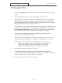
Note: Step 20 applies to the thermal printer when using the non-interlaced mode only.
In the interlaced input mode, the Check Front Panel Settings will be displayed as
shown in Figure 2-44.
Note: If the system has lost synchronization with the thermal printer, turn the system OFF
and power up again.
Important note:
Figure 2-43 has been removed because it is no longer applicable;
all subsequent Figures remain as originally numbered, i.e. Figure
2-44 is next.
20.
If you are unsure of what the printer front panel settings should be, select Check Front
Panel Settings, press <Enter> and follow the screen instructions (see Figure 244). Hit any key to continue.
Figure 2-44 Thermal Printer Front Panel Configuration screen
21.
Press <Esc> to return to the component selection window.
2-43
Polaroid ID3000 Service Manual
System Installation
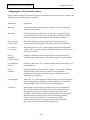
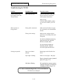
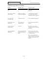
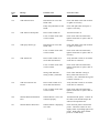
Adjusting the Color Portrait Camera
System settings affecting the appearance of portraits captured by the portrait camera or optional video
floppy player can be adjusted by system menus:
Adjustment
Explanation
Input type
Sets portrait values to match the type of camera or video floppy player
installed on your system.
Resolution
Sets the system for the resolution of the camera or video floppy player/
copystand installed on your system. Setting should remain at 512x480
unless the copystand is replaced by one with a different resolution.
Freeze contrast
(“Freeze gain”)
Determines contrast of portrait displayed on screen when Freeze is
selected during portrait capture. Also affects contrast of stored portrait.
Live contrast
(“Live gain”)
Determines contrast of “live” portrait displayed on screen during portrait
capture. (The “live portrait is the one displayed before Freeze is selected or
after Live is selected.)
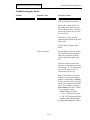
Freeze
brightness
(“Freeze Offset”)
Lightens or darkens the portrait displayed on the screen when Freeze is
selected during portrait capture. Also affects brightness of stored portrait.
Live brightness
offset”)
Lightens or darkens the “live” portrait displayed on the screen during (“Live
portrait capture.
Freeze
saturation
Increasing saturation boosts colors in “washed out” portraits. Reducing
saturation reduces colors that are too intense. Freeze saturation
affects the portrait on the screen when Freeze is selected. Also affects
saturation of stored portrait.
Live saturation
Affects the “live” portrait displayed during capture. (See Freeze Saturation
above for explanation of saturation’s effect on portrait.) Live saturation
adjustment applies only to portraits from video floppy player.
Freeze Hue
Increasing hue increases power of primary colors (red, green and blue)
where they dominate the secondary colors (yellow, magenta and cyan).
Increasing hue also decrease the power of the primary colors where
secondary colors dominate. If both saturation and hue are being adjusted,
saturation must be adjusted first. Freeze hue affects the portrait dis
played on the screen when Freeze is selected during portrait
capture.Also affects hue of stored portrait. Freeze hue adjustment
applies only to portraits from the video floppy player.
2-44
Polaroid ID3000 Service Manual
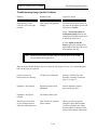
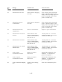
Live Hue
System Installation
Affects the “live” portrait displayed on the screen during portrait capture.
(See Freeze Hue above for explanation of hue’s effect on portrait.) Live hue
adjustment applies only to portraits from the video floppy player.
A detailed explanation of each adjustment procedure follows.
2-45
Polaroid ID3000 Service Manual
System Installation
Selecting the Image Type
Before making portrait adjustments, select the image type to which the settings will apply: ID-3000
portrait camera images or video floppy player images.
1.
If the issue and verify menu is not displayed, select it from the main menu.
2.
Select Adjust System to display the component selection window.
3.
Select Portrait Camera to open the camera settings window.
Figure 2-45 Camera Settings window
4.
Select Input Type to open the camera type window
5.
To adjust portraits from the video portrait camera, select RGB and press <Enter>.
To adjust portraits from the video floppy player, select Composite and press <Enter>.
6.
Select Resolution from the camera settings list to open the resolution selection window.
7.
Select 512x480 and press <Enter>. The camera settings list will return to the screen.
8.
Select Freeze Gain from the camera settings list.
9.
Type a value between 0 and 100 (0 produces the greatest contrast) to obtain the desired
amount of contrast in the stored portrait and press <Enter>.
10.
Select Live Gain and type a value between 0 and 100 to obtain the desired amount of
contrast in the “live” portrait and press <Enter>.
2-46
Polaroid ID3000 Service Manual
System Installation
NOTE: If the range of 0-100 is insufficient to achieve the desired contrast, select
Freeze Contrast or Live Contrast and adjust it in the same manner as Freeze
Gain or Live Gain. But DO NOT adjust Freeze Contrast or Live Contrast until
you have reached the limit of Freeze Gain or Live Gain. (The normal setting
for Freeze Contrast or Live Contrast is about 65.)
11.
Select Freeze Offset from the camera settings list. Type a value between 0 and 100 (100
produces the brightest portrait) to obtain the desired brightness in the stored portrait, and
press <Enter>.
12.
Select Live Offset and repeat the process done in step 11. Press <Enter>.
NOTE: The next four adjustments apply only to portraits captured by the video
floppy player, by selecting Composite as the Input Type.
13.
Select Freeze Saturation from the camera settings list. Type a value between 0 and 100
(100 produces the most saturation) to obtain the desired saturation in the stored portrait.
Press <Enter>.
14.
Select Live Saturation and repeat the process done in step 13. Press <Enter>.
15.
Select Freeze Hue from the camera settings list. Type a value between 0 and 100 to
obtain the desired contrast in the stored video floppy portrait. Press <Enter>.
16.
Select Live Hue, repeat the process of step 15 and press <Enter>.
17.
When all Camera Portrait adjustments have been made satisfactorily, select Done and
press <Enter> to save the settings.
2-47
Polaroid ID3000 Service Manual
System Installation
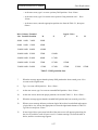
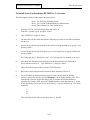
Adjusting the Signature Scanner
NOTE: Before performing the Signature Scanner adjustment steps 1 - 8 below,
first verify that the two switches and the thumbwheel on the Logitech
Scanner are set as follows:
a.
Looking at the Scanner from the rear, on the left side, set the switch nearest
the front (gray level or bi-level) to the / position (“a” in Figure 2-46).
b.
Also on the left side of the Scanner, set the thumbwheel
(contrast adjustment) to the center position (“b” in Figure 2-46).
(If the signature on a finished print is too light or dark, move the
thumbwheel toward the light or dark band accordingly.)
c.
Finally, on the right side of the Scanner, set the dots/inch switch at “2”
(“c” in Figure 2-46).
Figure 2-46 Signature Scanner switch settings
2-48
Polaroid ID3000 Service Manual
System Installation
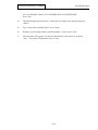
Adjustment Procedure
1.
Turn on the system and log on as CPS. From the Main Menu, select Issue and Verify
Badges, and from the Issue and Verify Menu, select Adjust System.
2.
Next select Signature Scanner to display the instructions for adjusting the signature
area (Figure 2-47). Follow screen instructions to adjust the signature.
Figure 2-47 Signature box adjustment instructions
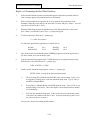
3.
Press the <Enter> key and the system will now ask you to insert the signature card.
4.
After the signature card has been signed with a medium-point black felt tip pen, insert the
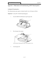
card signature-side up, cut corner end first, into the Scanner Figure 2-48).
Figure 2-48 Inserting card into Scanner
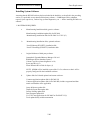
5.
The Scanner will pull the card in and then eject it. Remove the card from the Scanner.
The signature will now appear reversed on the screen.
2-49
Polaroid ID3000 Service Manual
6.
System Installation
Follow these instructions to position the rectangle around the signature area:
- to move the entire rectangle, use the regular cursor up/down/left/right
arrow keys.
- to change the height or width of the rectangle, use the arrow keys on
the numeric keypad. Be sure the Num Loc light on the keyboard is
lighted (<Num Loc> ON).
7.
When the signature rectangle is correctly sized and positioned, press <Enter>. The system
will return to the Adjust System menu.
8.
Check the signature position and contrast by making a print. (A print is the only reliable
check on signature quality: monitor display will not show contrast adequately.)
9.
If the signature is very light, adjust the contrast thumbwheel on the side of the Signature
Scanner (see “b” in Figure 2-44A).
10.
To return to the Issue and Verify menu, press <Esc>.
2-50
Polaroid ID3000 Service Manual
System Installation
Portrait Scanner Adjustment
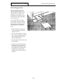
Calibrating the Scanner
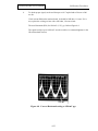
Use the following steps to calibrate the scanner whenever fine horizontal lines appear on the scanned
portrait (A).
If these lines reappear within a week of calibration, the scanner maay require service. Contact the
Polaroid Resource Center.
1.
Turn the scanner power switch on.
2.
Insert the white calibration card provided with the system - face-up into the scanner feed
tray.
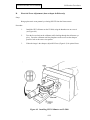
3.
Using a small screwdriver or a similar tool, momentarily press the calibration button recessed within the back panel of the scanner (A).
4.
Wait for the calibration card to be transported into the scanner and ejected.
5.
Remove the white calibration card from the scanner feed tray.
2-51
Polaroid ID3000 Service Manual
System Installation
Adjusting the Portrait Capture Area
When scanned portraits are consistently out of position or incorrectly sized, use the following procedure to adjust the area of the portrait captured by the scanner. If necessary, you can also temporarily
adjust the capture area to scan photographs with incorrectly sized or placed portraits.
1.
Select Adjust System from the operator's menu to open the adjust system menu.
2.
Select Color Portrait Scanner to display the scanner adjustment menu.
2-52
Polaroid ID3000 Service Manual
System Installation
3.
Select Adjust Scanned Area to display the area adjustment menu.
4.
Select Adjust Scanned Area to display the capture area adjustment screen.
5.
Type the dimension desired between the top edge of the photograph (or the top edge of the
carrier if a carrier is being used) and the top of the captured area.
If necessary, use the dimensional equivalents shown in the lower right of screen to convert
the measurement units to inches or centimeters.
Note:
The dimensional equivalents will change if you change the width of the captured area
from greater than 1.4 inches to less than 1.4 inches (or vice-versa). If you are not
achieving the expected results, recheck the displayed dimensional equivalents.
2-53
Polaroid ID3000 Service Manual
System Installation
6.
Press the Tab key to move the highlight on the adjustment screen. Then type the dimension
desired between the left edge of the photograph (or the left edge of the carrier if a carrier is
being used) and the left edge of the captured area.
7.
Press the Tab key to move the highlight on the adjustment screen, then type the dimension
desired for the width of the captured area.
Note:
8.
You cannot adjust the height of the captured area directly. The system automatically
calculates the height based on the width becaause the height-to-width ratio must
remain constant.
When all the desired dimensions have been entered, press the F10 key to save the new
values.
The message Insert Picture into Color Portrait Scanner appears.
9.
Insert a representative photograph into the scanner as shown, then wait for the scanner to
pull the picture in and eject it.
10.
Remove the picture from the scanner, then wait for the captured area to appear on the
screen.
11.
Carefully view the displayed portrait.
If the captured area is satisfactory, press the space bar to return to the scanner adjustment
menu. Then go to step 12.
2-54
Polaroid ID3000 Service Manual
System Installation
If the size or placement of the displayed portrait requires more adjustment, press the space
bar to return to the scanner adjustment menu. Then go back to step 4.
12.
Select Save and Exit to save the new settings and return to the system adjustment menu.
13.
Press the Esc key to return to the main menu.
Restoring the Factory-Set Capture Area
If you have adjusted the area captured by the scanner as described on page 115, you can restore the
captured area to the original settings as follows:
1.
Select Adjust System from the operator's menu to open the adjust system menu.
2.
Select Color Portrait Scanner to display the scanner adjustment menu.
2-55
Polaroid ID3000 Service Manual
System Installation
3.
Select Adjust Scanned Area to display the area adjustment menu.
4.
Select Restore Factory Settings to restore the settings and display the message Insert
Picture into Color Portrait Scanner.
5.
Insert a representative photograph into the scanner as shown, then wait for the scanner to
pull the photograph in and eject it.
6.
Remove the photograph from the scanner, then wait for the portrait to appear on the
screen.
2-56
Polaroid ID3000 Service Manual
7.
System Installation
Carefully view the displayed portrait.
If the captured area is satisfactory, press the space bar to return to the scanner adjustment
menu. Then go to step 8.
If the size or placement of the displayed portrait requires adjustment, press the space bar to
return to the scanner adjustment menu. Then go back to step 4 of the capture area adjustment procedure.
8.
Select Save and Exit to save the new settings and return to the system adjustment menu.
9.
Press the Esc key to return to the main menu.
Changing the Film Type Setting
Differences in the photographic film chemistry affect the way the ID3000 scanner senses color. For
example, the scanner senses the red background in a Polaroid instant photograph as slightly different
from the red background in a 35mm photograph, even though the two colors may appear identical to
the eye.
To assure accurate colors in scanned portraits, the ID3000 applies color correction settings for the
type of film being scanned. To change the settings being applied, select the type of film to be
scanned as follows:
1.
Select Adjust System from the operator's menu to display the adjust system menu.
2-57
Polaroid ID3000 Service Manual
System Installation
2.
Select Color Portrait Scanner to display the scanner adjustment menu.
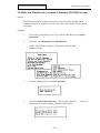
3.
Chose Select Film Type to display the film type menu.
2-58
Polaroid ID3000 Service Manual
System Installation
Exiting From the System
If you wish to exit the system at any time, use the following procedure:
1.
From any menu, return to the main menu by pressing <Esc> one or more times.
2.
From the main menu, select Log Out or Shut Off System.
3.
From the next menu displayed, select either Log Out or, to turn off the system, select Turn
System Off.
2-59
Polaroid ID3000 Service Manual
System Installation
Checking Laminator Temperature
Check the laminator’s built-in thermometer (Figure 2-49) for correct temperature (see below). If the
temperature is outside specification, change it to the correct temperature required by rotating the
adjustment pot on the end or top of the Laminator.
Laminator temperatures
Configuration “A” Laminators produce temperatures from
220 to 300 F, desireable for many non-Polaroid pouches.
Configuration “B” Laminators produce temperatures from
190 to 265 F, max., optimized for Polaroid pouches.
Thermal Laminators produce temperatures from 315 to 335 F.
Figure 2-49 Adjusting Laminator temperature
2-60
Polaroid ID3000 Service Manual
Troubleshooting/Diagnostics
SECTION 3 TROUBLESHOOTING/DIAGNOSTICS
Contents
Signature Scanner Diagnostics
Page
3-3
Troubleshooting Diagnostics
3-4
System Controllers and Adjustable Parameters
Files Required for Controllers
Configurable Parameters
Matrox Portrait Input
Matrox Preview Output
CI5000 Film Printer
TX1500 Thermal Printer
Black & White Thermal Printer
VS3000 Advanced (live/stored)
Signature Scanner
Support Board
3-7
3-8
3-10
3-14
3-17
3-18
3-20
3-22
3-22
3-24
3-25
CNF Files and Typical Contents
3-26
Troubleshooting the TX1500
Paper Jams
Belt Cleaning
3-32
3-33
3-34
Troubleshooting the CI5000+
3-35
Troubleshooting the Polaroid Color Scanner
3-39
Camera Offset Diagnostics
3-40
Troubleshooting Lamination Problems
3-42
Troubleshooting the Strobe
3-43
Troubleshooting Image Quality Problems
3-44
Troubleshooting Live/Freeze Image Problems
3-46
Error Message Table
3-47
3-1
This page intentionally blank.
Polaroid ID3000 Service Manual
Troubleshooting/Diagnostics
Signature Scanner Diagnostics
Note: before performing the Signature Scanner Diagnostics, first verify that the two switches and
the thumbwheel on the Logitech Scanner are set as follows:
a.
Looking at the scanner from the rear, on the left side, set the switch nearest the
front (gray level or bi-level) to the "/" position ("a" in Figure 3-1).
b.
Also on the left side of the Scanner, set the thumbwheel (contrast adjustment) to
the center position ("b" in Figure 3-1). (If the signature on a finished print is too
light or too dark, move the thumbwheel toward the light or dark band
accordingly).
c.
Finally, on the right side of the Scanner, set the dots/inch switch at "2" ("c" in
Figure 3-1).
Figure 3-1 Signature Scanner switch settings
3-3
Polaroid ID3000 Service Manual
Troubleshooting/Diagnostics
Troubleshooting Diagnostics
(Signature Scanner is not working)
1.
Select EXIT to DOS from the System Operation menu in the ID software.
2.
If the SIS_SCAN.CNF file exists in the AWS3F or AWS3T directory, make sure that
the "SIS" variable in the file is set to ON; if it is set to OFF and the application calls for a
signature input use any DOS editor to delete OFF and type ON, then save the file. Make
sure that the SIS_SCAN.CNF files in the ID2DATA directory have the same variable
value and reboot the system.
To test the motor controls and Card Present Detector (sensor) from the DOS directory,
type DEBUG and press <Enter>, then type the following commands.
Delay Command
0 338 74 <Enter>
0 338 7a <Enter>
0 338 7e <Enter>
Action
Motor goes forward (Pull the card in)
Motor stop
Motor goes reverse (Eject the card)
To test that the Photo-Interrupter is detecting the presence of the signature card, use the
following Debug Command.
Debug Command
i 339 <Enter>
Action
If card is present, DEBUG will respond with an
odd value (02).
If card is removed, DEBUG will respond with an
even value (03).
3-4
Polaroid ID3000 Service Manual
Troubleshooting/Diagnostics
The ID3000 software is set up to store images and signatures at one hard drive partition at a time.
Once this partition is full, the software will automatically switch to the next partition as defined in a
file called DRIVELIS.BB located in the APPS directory. This file is written by the Application
Group. It should only be changed when performing a hard drive upgrade. It is recommended to use a
DOS editor to add the partitions.
The DRIVELIS.BB defines the water level of each partition which means that when the available
free space on the partition reaches that water level mark, the system automatically starts storing on
the next defined partition. The water level for the database (D:) partition should be large enough to
allow the Database Reindex menu option.
The following table lists the various DRIVELIS.BB values according to each hard drive size.
A. Use the Configuration File option in the Calibration menu or any DOS.
NOTE: ReBoot the system after making
any changes in the DRIVELIS.BB File.
3-5
Polaroid ID3000 Service Manual
Troubleshooting/Diagnostics
The following table which displays the approximate image storage capacity for the different hard
drive sizes, is based on the following assumptions:
Image Sizes:
Portrait:
Signature
10KB
2KB
Data Record Sizes:
Data Record length:
PFIELD and SFIELD:
Indexed fields:
512 bytes
256 bytes each
12 character ID#; two 24-byte fields
Image Storage Capacity
Disk size
48MB
85MB
120MB
180MB
240MB
340MB
765MB
Portrait Only
2600
5700
8700
13500
19000
27100
54700
Portrait and Signature
2200
4700
7200
11100
15600
22300
45100
3-6
Polaroid ID3000 Service Manual
Troubleshooting/Diagnostics
System Controllers and Adjustable Parameters
The Version 2 system devices like color camera, CI5000, TX1500, HP laser jet Etc. are all
controlled by specific software modules in the system. These modules are called Device Controllers
and there exists exactly one Device Controller for each Device/function pair. For example:
Device/Function
Portrait Capture Matrox Illuminator
Signature Scanner
Controller
MIC_ILUM
SIS_SACN
These device controllers require various parameters to be adjustable externally for calibration and
control. These parameters are located in a set of configuration files designated by a .CNF extension.
These files are named in such a way to correspond to the appropriate device controller. For example:
Controller
MIC_ILUIM
SIS_SCAN
Configuration File
MIC_ILUM.CNF
SIS_SCAN.CNF
The following is a list of the currently available controllers for ID3000 version II software system
and a brief description of each controller and its necessary configuration file and contents.
MOC_ILUM
- Portrait output controller for Matrox Illuminator.
- Used to render a card layout in video memoryof the Matrox
Illuminator image capture board.
MIC_ILUM
- Portrait input controller for Matrox Illuminator.
- Used to capture a portrait with the Matrox
HOC_HPLJ
- Hewlett Packard output hardcopy controller.
- Used to output a badge (DOSSIER) onto the the HP III laser
printers.
PIC_COPY
- Portrait input controller for copy stand.
- Used to input portraits by grabbing a picture of an existing picture
using the Matrox Illuminator Image Capture Board.
POC_VGA
- Portrait output controller for VGA card.
- Used to render a card layout in the VGA video memory with the
Polaroid VGA extender card. This card allows true 15 bit per
pixel color from a VGA card. This controller only works with the
extender card.
POC_N9
- Portrait output controller for Number 9 board.
3-7
Polaroid ID3000 Service Manual
Troubleshooting/Diagnostics
- Used to render a card layout in video memory of a Number 9
corp. pepper plus display adapter.
POC_8514
- Portrait output controller for Paradise 8514a card.
- Used to render a card layout in video memory of the Paradise
8514a display adapter Illuminator image capture board.
SIS_SCAN
- Signature input controller for Logitech based scanner.
HOC_CI5K
- CI-5000 color film recorder controller; used to print badges on
the CI-5000 plus.
HOC_TP
- TX-1500 thermal printer controller; used to control and print
badges on the Polaroid TX1500 Color Thermal Printer.
HOC_BWTP
- Black and white (Sony) video printer controller. Used to print
temporary badges. A Matrox board is also required.
PCS
- Input controller for Polaroid Color Scanner.
- Used to capture images from color prints using the CS-500i.
SUPPORT
- Not a controller but a toolkit to allow device independent
operation of the support board. Several controllers use it.
WS_VERIFY
- Live/still controller for the Advanced Verification Station using the
matrox board,
FILES REQUIRED FOR EACH CONTROLLER:
The following lists each controller with it appropriate data files.
HOC_HPLJ
Hoc_hplj.sot
Hoc_hplj.cnf
- Screen object file.
- Configuration file.
PIC_STIL
Pic_scrn.sot
Stiltbls.dat
Pic_stil.cnf
- Screen object file.
- Tables for decoding from NTSC to RGB.
- Configuration file.
PIC_COPY
Pic_scrn.sot
Copytbls.dat
Pic_copy.cnf
- Screen object file.
- Tables for decoding from NTSC to RGB.
- Configuration file.
3-8
Polaroid ID3000 Service Manual
POC_VGA
Vgalut.dat
Poc_vga.cnf
POC_N9
Poc_n9.cnf
POC_8514
P8514lut.dat
Poc_8514.cnf
Troubleshooting/Diagnostics
- Output look up tables for the VGA output controller.
Contains an ascii list of 256 levels for portrait drawing
with the card language. The format is one ascii number
on each line followed by a carraige return line feed. The
order is:
256 - RED
256 - GREEN
256 - BLUE
256 - LUMA
- Configuration file.
- Configuration file.
- Output look up tables for the 8514a output controller.
Contains an ascii list of 256 levels for portrait drawing
with the card language. The format is one ascii number on
each line followed by a caraige return line feed. The order
is:
256 - RED
256 - GREEN
256 - BLUE
256 - LUMA
- Configuration file.
MOC_ILUM
Moc_ilum.cnf - Configuration file.
MIC_ILUM
Mic_scrn.sot
Mic_ilum.cnf
Mtrx_lut.dat
- Screen object file.
- Configuration file.
- Input lookup table
HOC_CI5K
Hoc_scrn.sot
Dpalette.cfg
Hoc_ci5k.cnf
ID669.FLM
CI5k_lut.dat
- Screen object file.
- Palette toolkit configuration file.
- Controller configuration file
- Fast film table
- Lookup table/color-correction matrix file
3-9
Polaroid ID3000 Service Manual
Troubleshooting/Diagnostics
HOC_TP
Hoc_tp.sot
Hoc_tp.cnf
TP_lut.dat
- Screen object file
- Configuration file
- Lookup table/color-correction matrix file
BW_TP
Bwtp.sot
Bwtp.cnf
- Screen object file
- configuration file
PCS
Pcsscrn.sot
Pcs.cnf
Pcsfilm.bb
- Screen object file
- configuration file
- current list of supported films
SIS_SCAN
Sis_scrn.sot
Sis_scan.cnf
- Screen object file
- Configuration file
SUPPORT
Support.cnf
- configuration file
WS_VERIFY
Ver_ilum.cnf
Ver_scrn.sot
- configuration file
- screen object file
CONFIGURABLE PARAMETERS FOR EACH CONTROLLER:
The following lists each controllers configuration file and the parameters contained inside. These
parameters are loaded by the controller during initialization and may be changed to modify the
operation of the system. All parameters are contained in the .cnf files; the format consists of
2 parts - (1) The system bulletin board name, and (2) the data value. Both are enclosed within double
quotes as follows:
“NAME”,”VALUE”;
The value may be text or numbers. Always use upper case. All numbers are in decimal unless noted
otherwise.
HOC_HPLJ.CNF
- Hewlett Packard laser printer output controller.
“DOSSIER_LAYOUT_FILE”
This is the name of the .TOK file (a compiled .IDC program) which defines the
layout for the dossier controller which is the default. This value is a filename of the
.TOK file.
3-10
Polaroid ID3000 Service Manual
Troubleshooting/Diagnostics
“DOSSIERLPT”,”1";
This is the LPT number (1,2,3) of the printer port to be used for generating the
DOSSIER. The normal value is 1 which indicates LPT1.
“DOSSIER_DIAG_LAYOUT”,””;
This value is not currently used.
“HPLJ_ORIENT”,””;
This value is not currently used.
“HPLJ_BRIGHT”,”4";
This value controls a simple brightness adjustment for the portraits which are
generated with the DOSSIER controller. The values are 0 through 7. “3” is
considered the normal value.
“HPLJ_CONTRAST”,”159";
This value controls a simple contrast adjustment for the portraits which are
generated with the DOSSIER controller. The values are 0 through 255. “128” is
considered the normal value. 0 indicates ZERO contrast and is a useless value. 255
is 2 times the normal contrast. The generally useful range is about 80-180.
“HPLJ_CURVE”,””; (This value is not currently used.)
“HPLJ_FONT1”,””;
“HPLJ_FONT2”,””;
“HPLJ_FONT3”,””;
“HPLJ_FONT4”,””;
“HPLJ_FONT5”,””;
These are full path names of font files (in HP format) which should be transmitted
to the HPLJ printer when the controller is initialized. When using a series 2 printer
this is really the only way to get interesting fonts. With the Series 3 printer the
scalable fonts are available.
PCS.CNF
- CS-500 Polaroid Color Scanner (PCS)
PCS_COLORMODE -Internal colormode in the CS-500 controller. Possible values:
COLOR - 24 bit color
BW - Black and white
default value: COLOR
PCS_RESOLUTION -
Scanning resolution in DPI possible values:
DPI125 - Scan at 125 DPI, positions in 125 dpi
DPI250 - Scan at 250 DPI, positions in 250 dpi
DPI500 - Scan at 500 DPI, positions in 500 dpi
Default value: DPI125
3-11
Polaroid ID3000 Service Manual
Troubleshooting/Diagnostics
PCS_PIXELFORMAT - Selects the method the CS500 controller uses to store image
data in memory. Possible values:
CHUNK =
send the data in continuous format of red, green
and blue data bytes.
LINE =
send scan line’s worth of red pixels followed by
scan line of green and<+!><-!> then a scan line of blue.
PLANE =
send an entire plane of red image data followed
by an entire plane of green and then a plane of blue.
Default: PLANE
PCS_AOIX1
PCS_AOIX2
PCS_AOIY1
PCS_AOIY2 - The PCS_AOIxn values define an “Area of Interest” which is the
area of the image to be scanned. These values define a rectangle
with X1,Y1 being the upper left of the rectangle and X2,Y2 being
the lower right. The units specified for these parameters are in DPI
for the resolution selected. Default values:
X1 = 080
Y1 = 080
X2 = Maxwidth for 125 DPI
Y2 = Maxheight for 125 DPI
X2-X1 is the width of the image to be scanned in DPI
Y2-Y1 is the height of the image to be scannedin DPI
PCS_DATANAME - The name of the film color lookup table downloaded to the scanner,
for color balancing the scannedimages based on the film type. The
default table is PCSDFLT.DAT, which is for 35mm film and is also
acceptable for Spectra film.
PCS_HARDBUF -
The internal size of the PCS hardware buffer. Older models of the
scanner have smaller buffers than the newer “FIFO” (CS-500i)
models of the scanner. Possible values:
2MEG - 2 Megabyte “FIFO” (CS-500i) scanner.
0MEG - Older 64K model of the scanner.
Default value:
2MEG
PCSWINDOW -
This variable enables and disables a menu display when the
controller is activated for scanning. Possible values:
OFF - Bypass menu, scan immediately
ON - Display the menu
PCS -
This variable enables or disables the entire PCS controller.With this
value set to “OFF” the controller behaves as if it did not exist. This
3-12
Polaroid ID3000 Service Manual
Troubleshooting/Diagnostics
value may also be checked by application scripts to determine if the
controller is activiated. Possible values:
ON - All controller entry points are enabled
OFF - All controller entry points are disabled
PCS_RGBBUF -
This variable defines the name of the RGB EMS buffer which is to
be used for the scanned image. By specifing different names for the
destination buffer, the application can flip between different RGB
buffers allowing more than one scanned image to reside in the
system default:
DRGBB - The standard RGB buffer name
PCS_MOTORADJUST - This variable defines the parameters for the motor.
Default value:
E8,CF,9D,A0,35,230,1E0
Possible values:
These values are in hexadecimal (Base 16)format. Only the
last two variables on the line should ever be changed.
These variables are the Picture Eject Distance (PED) and
the Picture Input Distance (PID), respectively.The PID
corresponds to how far the scanner continues to “pull” the
image into the machine after it has noticed the trailing edge.
The only reasons for changing thesevariables are if the
picture is “swallowed” by the scanner, or if any of the
wanted data in the picture cannot be captured by
manipulating the PCS_AOIxx values also in this .CNF file.
The scaling for these variables is approximately 100h (100
hex) to 1 inch. It is a good idea to first change only the
PID, then add 50h for the PED. As an example, assume
you are scanning a photo laminated with clear plastic. The
“electronic eye” of the scanner would not be able to detect
the plastic, and would consider the end of the photo to be
the trailing edge. In order to pull in the entire card,
including the plastic, the PID should be increased about half
an inch (80h) to 260h (1E0h + 80h).The PED would then
become 2B0h (260h + 50h).
PCS_MUST_REMOVE This variable determines whether or not the user must
remove the photo once the scan is complete, before he/she
can continue. It is a security feature in conjunction with the
auto-feed feature. Possible values:
YES - User must remove photo
NO - User need not remove photo
Default value:
YES
3-13
Polaroid ID3000 Service Manual
Troubleshooting/Diagnostics
POC_VGA.CNF VGA output controller.
CFR_LAYOUT_FILE- Card layout file to be drawn.
POC_N9.CNF - NUMBER NINE graphics adapter output controller.
CFR_LAYOUT_FILE Card layout file to be drawn.
POC_8514.CNF - Paradise 8514a output controller.
CFR_LAYOUT_FILE Card layout file to be drawn.
DSP.CNF
DSP_BASE_ADDRESS
- Base I/O Address of the DSP Board, Was 816 in
version 1 and early version 2 now moved to 312.
MATROX PORTRAIT INPUT CONTROLLER CONFIGURATION FILE
File Name: MIC_ILUM.CNF
Objects:
MIC_RESOLUTION
Type: string
Determines the frame grabber resolution during portrait capture. Available options
are “640X480” (2 Mbyte board only), “512X480”, and “512X400”. Only
“640X480”, which gives a 1:1 pixel aspect ratio, or “512X480”, which gives a 5:4
aspect ratio, are recommended.
VIDEO_IN
Type: string
Determines camera type. Possible settings are “RGB” for RGB camera, or “COMP”
for composite (NTSC) camera or still video player.
FAST_SYNC
Type: string
Is “YES” if the special Matrox board modified for fast genlock is installed, otherwise it
should be “NO”.
SCRUNCHED
Type: string
Is “YES” to cause the screen to remain scrunched after exiting the portrait capture
menu. If “NO”, the screen is reset after this menu to restore it to normal size. “YES” is
required if a TX-1500 thermal printer with non-interlaced input is installed, in order to
prevent noise on the print.
RGB_STROBE
Type: string
Is “YES” to enable flash unit for RGB camera, otherwise “NO”.
COMP_STROBE
Type: string
Is “YES” to enable flash unit for composite camera, otherwise “NO”. Should be “NO”
for still video player.
3-14
Polaroid ID3000 Service Manual
Troubleshooting/Diagnostics
LIVE_IRIS
Type: string numeric
The 8 bit value sent to the iris DAC for live mode. Not used for the current support
board. May be used if an iris DAC is someday installed.
FREEZE_IRIS
Type: string numeric
The 8 bit value sent to the iris DAC for freeze mode. Not used for the current support
board.
STROBE_RECHARGE
Type: string numeric
The number of seconds required to recharge the strobe. This enforces a minimum time
between strobe firings.
RGB_GAIN
Type: string numeric
Sets DAC gain at the video input during freeze for RGB cameras. Range “0” to “100”.
Note that 0 is highest gain, 100 is lowest gain.
RGB_OFFSET
Type: string numeric
Sets the brightness during freeze for RGB cameras. Range “0” to “100”.
RGB_CONTRAST
Type: string numeric
Sets the contrast during freeze for RGB cameras. Range “0” to “100”, with 100 being
highest contrast.
LIVE_RGB_GAIN
LIVE_RGB_OFFSET
LIVE_RGB_CONTRAST
Same as above, but for live mode.
COMP_GAIN
Type: string numeric
Sets DAC gain during freeze for NTSC cameras. Range “0” to “100”. Note 0 is
highest, 100 is lowest gain.
COMP_OFFSET
Type: string numeric
Sets the brightness during freeze for NTSC cameras. Range “0” to “100”.
COMP_CONTRAST
Type: string numeric
Sets contrast during freeze for NTSC cameras. Range “0” to “100”, with 100 being
highest contrast.
COMP_SATURATION
Type: string numeric
Sets color saturation during freeze for NTSC cameras. Range “0” to “100”. 0 is no
color.
COMP_HUE
Type: string numeric
Sets hue during freeze for NTSC cameras. Range “0” to “100”.
3-15
Polaroid ID3000 Service Manual
LIVE_COMP_GAIN
LIVE_COMP_OFFSET
LIVE_COMP_CONTRAST
LIVE_COMP_SATURATION
LIVE_COMP_HUE
Same as above, but for live mode.
Troubleshooting/Diagnostics
Type: string numeric
AOI_XMIN
Type: string numeric
AOI_XMAX
AOI_YMIN
AOI_YMAX
Defines the area of interest in the portrait. Range is “0” to “255”
for AOI_XMIN
and AOI_XMAX, and “0” to “383” for AOI_YMIN and AOI_YMAX.
FACE_BRIGHT
Type: string numeric
Enables hardware face brightener. “0” disables, “1” enables. Note: may be
superseded by software face brightener.
FACE_BRIGHT_VALUE
Type: string numeric
The change in gain value used when face brightener is enabled. Reasonable values
range from 0 to 20 or so. This can be one or two numbers. If two numbers are used,
the face brightener will have two levels (off, level 1, level 2); otherwise it will be one level
(off, on). Example: “10 15” for a two-step brightener.
FACE_BRIGHT_OFFSET
Type: string numeric
The change in offset value used when face brightener is enabled. This can be one or two
numbers. The number of levels must be the same as in FACE_BRIGHT_VALUE.
Example: “10 20“ for two-step brightener.
PORTRAIT_BACKGROUND_THRESHOLD Type: string numeric
Sets the threshold for determining the background color for Electronic Background (soft
ware chroma keying). Typical value is “30”. Increase for noisy backgrounds or if parts
of the background are not being substituted. Decrease if parts of the person are being cut
away.
PORTRAIT_BACKGROUND_ITER
Type: string numeric
Controls the halo for Electronic Background. Typical value is “4”. Increase to remove
more of the halo. Decrease if too much of the person is being shaved off.
NOTE
The following configuration objects are set by the calibration routine (MCAL) and the
adjust system menu:
MIC_RESOLUTION
VIDEO_IN
LIVE_IRIS
COMP_GAIN
COMP_OFFSET
COMP_CONTRAST
3-16
Polaroid ID3000 Service Manual
Troubleshooting/Diagnostics
FREEZE_IRIS
RGB_GAIN
RGB_OFFSET
RGB_CONTRAST
LIVE_RGB_GAIN
LIVE_RGB_OFFSET
LIVE_RGB_CONTRAST
COMP_SATURATION
COMP_HUE
LIVE_COMP_GAIN
LIVE_COMP_OFFSET
LIVE_COMP_CONTRAST
LIVE_COMP_SATURATION
LIVE_COMP_HUE
The following objects can only be set by directly editing the configuration file:
FAST_SYNC
RGB_STROBE
COMP_STROBE
SCRUNCHED
STROBE_RECHARGE
PORTRAIT_BACKGROUND_THRESHOLD
PORTRAIT_BACKGROUND_ITER
FACE_BRIGHT
FACE_BRIGHT_VALUE
FACE_BRIGHT_OFFSET
AOI_XMIN
AOI_XMAX
AOI_YMIN
AOI_YMAX
MATROX PREVIEW OUTPUT CONTROLLER CONFIGURATION FILE
File Name: MOC_ILUM.CNF
Objects:
CFR_LAYOUT_FILE
Card layout file to be drawn.
Type: string
MOC_RESOLUTION
Type: string
Determines the display resolution during card preview. Available options are
“640X480” (2 Mbyte board only), “1024X768” (2 Mbyte board and multiscan monitor
only), “512X480”, and “512X400”.
MOC_INTERLACE
Type: string
Determines if the preview screen is interlaced. “Y” is interlaced, “N” is non-interlaced.
VGA monitors require “N”. 1024X768 resolution requires “Y”.
MOC_XSIZE
Type: string numeric
MOC_YSIZE
Determines the physical size of the card layout on the screen. The logical card
coordinates are mapped to this area. For downward compatibility with card layouts
designed for the Paris board, it is possible for these parameters to be larger than the
actual monitor resolution, since these cards are drawn with die cutter offsets built into the
card graphics commands. New card layouts should not have any die cutter offsets. They
should be drawn to the edges of the logical coordinate space.
3-17
Polaroid ID3000 Service Manual
Troubleshooting/Diagnostics
MOC_XOFFSET
Type: string numeric
MOC_YOFFSET
Used to position the card on the preview screen. Can be positive or negative. Use in
combination with CARD_XSIZE and CARD_YSIZE to fit the card image to the preview
screen.
CI-5000 FILM PRINTER CONFIGURATION FILE
File Name: HOC_CI5K.CNF
Objects:
HOC_RESOLUTION
Type: string
Determines the resolution of the printable area of the film. All of the individual cards
must fit within this area. Practically any values are allowed, but limited by the amount of
memory in the CI5000. Typical values are “1024X768”, “1200X800”, etc.
CARDS_PER_SHEET
Type: string numeric
Is “1” for a 1 UP application, “2” for 2 UP.
CARD1_XSIZE
Type: string numeric
CARD1_YSIZE
Determines the physical size of the first card on the film. The logical coordinates are
mapped to this area. Note that X is always along the long dimension of the film, even for a
2 UP.
CARD1_XOFFSET
Type: string numeric
CARD1_YOFFSET
Used to position the first card on the film. Used in conjunction with CARD1_XSIZE and
CARD1_YSIZE to fit the card to the die cutter.
CARD2_XSIZE
Type: string numeric
CARD2_YSIZE
CARD2_XOFFSET
CARD2_YOFFSET
Determines the size and position of the second card on the film. Used only for a 2 UP
application.
PORTNO
It is ignored for a SCSI CI-5000+.
Type: string numeric
LIGHTEN_DARKEN
Type: string numeric
Lightens or darkens the entire card. Ranges from “0” to “6”, with “3” being the nominal
value, “6” twice as light, “0” half as light.
3-18
Polaroid ID3000 Service Manual
Troubleshooting/Diagnostics
COLOR_BALANCE
Type: string
Sets the color balance of the entire card by specifying the brightness of each color plane. It
is a sequence of three numbers “R G B”, where R sets the Red brightness, G the Green,
and B the Blue. Each number ranges from 0 to 6, with 3 being nominal, 6 twice as light, 0
half as light.
EXPOSURE_TIME
Type: string
Allows additional control over the lightness and color balance of the card by adjusting the
exposure time of each color plane. It is a sequence of three numbers “R G B”. Each
number ranges from 50 to 200, with 100 being nominal.
LUMINANT
Type: string
Allows additional control over the lightness and color balance of the card by adjusting the
brightness of the CRT. It is a sequence of three numbers “R G B”. Each number ranges
from 50 to 200, with 100 being nominal.
LIGHTEN_DARKEN_PORTRAIT
Type: string numeric
Allows control over the portrait lightness above and beyond the adjustments described
above for the entire card. Ranges from “0” to “6”, with “3” being nominal.
COLOR_BALANCE_PORTRAIT
Type: string
Allows control over the color balance of the portrait. It is a sequence of three numbers
“R G B”. Each number ranges from 0 to 6, with 3 being nominal.
HOC_TINT_TABLE
Type: string
An optional list which modifies how the LIGHTEN_DARKEN_PORTRAIT and
COLOR_BALANCE_PORTRAIT work. It is a list of 13 exposure factors indexed
by LIGHTEN_DARKEN_PORTRAIT+COLOR_BALANCE_PORTRAIT (note this
ranges from 0 to 12). A factor of 64 is equivalent to the nominal exposure, 32 is half the
exposure, 128 is twice, etc.
USERDELAY
Type: string numeric
Specifies the time out in seconds if the user does not respond to a particular command.
DEVTIME
Type: string numeric
Specifies the film development time as in index into a table: 0 - 45 sec, 1 - 50 sec, 2 - 60
sec, 3 - 70 sec, 4 - 80 sec, 5 - 90 sec, 6 - 100 sec, 7 - 120 sec.
FORCE_PRINT
Type: string
Set by the application when it wants to force a single card in a 2-up configuration.
DP_FILM_TABLE
Type: string
The name of a film table that is to be downloaded into the CI-5000.
Typical file is “ID669.FLM”, the fast film table.
3-19
Polaroid ID3000 Service Manual
Troubleshooting/Diagnostics
DP_CAMERA_OVERSCAN
Type: string numeric
The amount (in percent) that the raster size should exceed the print area on the film. This is
to allow for variations between film packs and lots of film. It is read by the calibration
program CICAL.
DP_CAMERA_ADJUST_X
Type: string numeric
DP_CAMERA_ADJUST_Y
DP_CAMERA_ADJUST_Z
These parameters are set by the calibration program CICAL. Normally the user would not
know how to set them. The values are unique to a particular CI-5000/camera back combi
nation.
CFR
Type: string
Enables or disables the film printer. Can be “ON” or “OFF”.
TX-1500 THERMAL PRINTER CONFIGURATION FILE
File Name: HOC_TP.CNF
Objects:
HOC_TP_RESOLUTION
Type: string
Determines the resolution of the printable area of the film. All of the individual cards
must fit within this area. This should be “640X480”, which requires the 2Mbyte Matrox
board.
HOC_TP_CARDS_PER_SHEET
Type: string numeric
Is “1” for a 1 UP application, “2” for 2 UP.
HOC_TP_CARD1_XSIZE
Type: string numeric
HOC_TP_CARD1_YSIZE
Determines the physical size of the first card on the film. The logical coordinates are
mapped to this area. Note that X is always along the long dimension of the film, even for a
2 UP.
HOC_TP_CARD1_XOFFSET
Type: string numeric
HOC_TP_CARD1_YOFFSET
Used to position the first card on the film. Used in conjunction with CARD1_XSIZE and
CARD1_YSIZE to fit the card to the die cutter.
HOC_TP_CARD2_XSIZE
Type: string numeric
HOC_TP_CARD2_YSIZE
HOC_TP_CARD2_XOFFSET
HOC_TP_CARD2_YOFFSET
Determines the size and position of the second card on the film. Used only for a 2 UP
application.
3-20
Polaroid ID3000 Service Manual
Troubleshooting/Diagnostics
HOC_TP_LIGHTEN_DARKEN
Type: string numeric
Lightens or darkens the entire card. Ranges from “0” to “6”, with “3” being the nominal
value, “6” twice as light, “0” half as light.
HOC_TP_COLOR_BALANCE
Type: string
Sets the color balance of the entire card by specifying the brightness of each color plane. It
is a sequence of three numbers “R G B”, where R sets the Red brightness, G the Green,
and B the Blue. Each number ranges from 0 to 6, with 3 being nominal, 6 twice as light, 0
half as light.
HOC_TP_LIGHT_DARK_PORT
Type: string numeric
Allows control over the portrait lightness above and beyond the adjustments described
above for the entire card. Ranges from “0” to “6”, with “3” being nominal.
HOC_TP_COLOR_BAL_PORT
Type: string
Allows control over the color balance of the portrait. It is a sequence of three
numbers “R G B”. Each number ranges from 0 to 6, with 3 being nominal.
HOC_TP_ALL_TINT_TABLE Type: string
An optional list which modifies how the HOC_TP_LIGHTEN_DARKEN and
HOC_TP_COLOR_BALANCE work. It is a list of 13 exposure factors indexed by
LIGHTEN_DARKEN + COLOR_BALANCE (note this ranges from 0 to 12). A factor
of 64 is equivalent to the nominal exposure, 32 is half the exposure, 128 is twice, etc.
HOC_TP_PORT_TINT_TABLE
Type: string
An optional list which modifies how the HOC_TP_LIGHT_DARK_PORT and
HOC_TP_COLOR_BAL_PORT work. It is a list of 25 exposure factors indexed by
HOC_TP_LIGHT_DARK_PORT + HOC_TP_COLOR_BAL_PORT +
HOC_TP_LIGHTEN_DARKEN + HOC_TP_COLOR_BALANCE (note this ranges
from 0 to 24). A factor of 64 is equivalent to the nominal exposure, 32 is half the
exposure, 128 is twice, etc.
FORCE_PRINT
Type: string
Set by the application when it wants to force a single card in a 2-up configuration.
HOC_TP_MAX_PRINT_TIME
Type: string numeric
The time required for a sheet to print. This timing is done by the software when status is not
available.
HOC_TP_INTERLACE
Type: string
Specifies whether the input to the thermal printer is interlaced (“Y”) or non-interlaced
(VGA) (“N”). The default as of Ver. 2.3 is “Y”.
COLOR_THERM_PRINT
Type: string
Enables or disables the thermal printer. Can be “ON” or “OFF”.
3-21
Polaroid ID3000 Service Manual
Troubleshooting/Diagnostics
BLACK AND WHITE THERMAL PRINTER CONFIGURATION FILE
File Name: BWTP.CNF
Objects:
BW_TP (string): Enables BW thermal printer. ON=Enabled, OFF= disabled.
BWTP_INTERLACE (string): Determines whether the printer uses an interlaced video
signal (YES/NO).
BWTP_REMOTE (string): Determines whether the printer is controlled by a remote button
(YES/NO).
BWTP_RESOLUTION (string numeric): Sets the video resolution used by the printer.
Normally “640X480”.
BWTP_XOFFSET (string numeric): Sets the printing offset in the X direction.
BWTP_YOFFSET (string numeric): Sets the printing offset in the Y direction.
BWTP_XSIZE (string numeric): Sets the physical size for the ID card or temporary pass, in
the x-direction.
BWTP_YSIZE (string numeric): Sets the physical size for the ID card or temporary pass, in
the y-direction.
VS-3000 ADVANCED (LIVE/STORED) CONFIGURATION FILE
File Name: VER_ILUM.CNF
Objects:
CFR_LAYOUT_FILE (string): Sets the name of the verification layout file. This layout
positions the live and stored images on the verification screen.
VER_LIVE_XSIZE (string numeric):
VER_LIVE_YSIZE (string numeric): Set the number of pixels in the X and Y direction used
by the portrait live window. Should correspond to the window size in the verification layout
file.
VER_LIVE_XPOS (string numeric):
VER_LIVE_YPOS (string numeric): Set the X,Y location of the upper left corner of the
portrait live window. Should correspond to the window position in the verification layout
file.
3-22
Polaroid ID3000 Service Manual
Troubleshooting/Diagnostics
VER_RESOLUTION (string): Determines the frame grabber resolution during portrait
capture. Available options are “640X480” (2 Mbyte board only), “512X480”, and
“512X400”. Only “640X480”, which gives a 1:1 pixel aspect ratio, or “512X480",
which gives a 5:4 aspect ratio, are recommended.
VER_XOFFSET (string numeric):
VER_YOFFSET (string numeric): Used to position the verification layout on the screen.
Should be positive. Use in combination with VER_XSIZE and VER_YSIZE to fit the
verification layout on the screen.
VER_XSIZE (string numeric):
VER_YSIZE (string numeric): Determines the physical size of the verification layout on the
screen. The logical coordinates are mapped to this area.
VER_INTERLACE (string): Determines if the verification screen is interlaced. “Y” is
interlaced, “N” is non-interlaced. VGA monitors require “N”. 1024X768 resolution
requires “Y”.
VER_VIDEO_IN (string): Determines camera type. Possible settings are “RGB” for
RGB camera, or “COMP” for composite (NTSC) camera or still video player. Default is
“COMP”.
FAST_SYNC (string): Is “YES” if the special Matrox board modified for fast genlock is
installed; otherwise it should be “NO”.
LIVE_IRIS (string hex): The 8 bit value sent to the iris DAC for live mode. Not used for
the current support board. May be used if an iris DAC is someday installed.
VER_RGB_GAIN (string numeric): Sets DAC gain at the video input during live mode for
RGB cameras. Range “0” to “100”. Note that 0 is highest gain, 100 is lowest gain.
VER_RGB_OFFSET (string numeric): Sets the brightness during live mode for RGB
cameras. Range “0” to “100”.
VER_RGB_CONTRAST (string numeric): Sets the contrast during live mode for RGB
cameras. Range “0” to “100”, with 100 being highest contrast.
VER_COMP_GAIN (string numeric): Sets DAC gain during live mode for NTSC
cameras. Range “0” to “100”. Note 0 is highest, 100 is lowest gain.
VER_COMP_OFFSET (string numeric): Sets the brightness during live mode for NTSC
cameras. Range “0” to “100”.
VER_COMP_CONTRAST (string numeric): Sets contrast during live mode for NTSC
cameras. Range “0” to “100”, with 100 being highest contrast.
3-23
Polaroid ID3000 Service Manual
Troubleshooting/Diagnostics
VER_COMP_SATURATION (string numeric): Sets color saturation during live mode for
NTSC cameras. Range “0” to “100”. 0 is no color.
VER_COMP_HUE (string numeric): Sets hue during live mode for NTSC cameras.
Range “0” to “100”.
COMPARE_LIVE (string): set to “ON” when system is configured with Live Video
Comparison (live/still) option. Set to “OFF” otherwise.
SIGNATURE SCANNER CONFIGURATION FILE
File Name: SIS_SCAN.CNF
Objects:
SIG_XSTART & SIG_YSTART (string numeric): Determine the upper left corner of the
signature box in dots, where “upper left” is defined as the corner opposite the cut corner of
the card regardless of the signature orientation.
SIG_XSIZE & SIG_YSIZE (string numeric): Determine the width and height of the
signature box in dots. SIG_XSIZE is always across the short dimension of the card, and
SIG_YSIZE is always across the long dimension of the card, regardless of the signature
orientation.
SIG_DPI (string numeric): Determines the resolution of the scanner in dots per inch.
Possible values are “100”, “200”, “300”, “400”. It must match the switch setting on
the scanner.
SIG_DIRECTION (string numeric): Determines the orientation of the signature on the
card. Possible values are “0”, “1”, “2”, or “3”. “3” is the orientation of the Paris
signature card, assuming the card is inserted with the cut corner going in. “0” is the typical
orientation for the scanner hardware which scans on the way in.
SIG_NUM_MARKS (string numeric): Determines the number of index marks to be
located in order to set the origin of the card. The origin is set at the bottom of the specified
index mark. The value can be 0 if there is no index mark on the card, although without a
mark the y-offset (SIG_YSTART) of the area of interest from the origin will not be reliable.
The value currently should be 1, since only one image per card should be scanned.
SIG_MAX_CARD (string numeric): The maximum length, in inches, to be scanned while
locating index marks. This length should not exceed that of the card, but cannot be less than
the distance from the top of the card to the bottom of the index mark.
SIG_MAX_SCAN (string numeric): The maximum scannable length from the card origin
(i.e., bottom of specified index mark), in inches. This value determines the length of the area
3-24
Polaroid ID3000 Service Manual
Troubleshooting/Diagnostics
to be displayed during configuration, and should not exceed the distance from the bottom
of the index mark to the point where the motor must be reversed.
SIS (string): ON or OFF, depending on whether or not the application uses the signature
scanner.
SIG_COMPRESS (string): Determines the type of compression used. For the ID2000GS
or the ID3000, this should be “G3” for CCITT Group 3.
SIG_THRESHOLD (string): Threshold for gray-scale signature scanner. Typical value is
“20”.
SUPPORT BOARD CONFIGURATION FILE
File Name: SUPPORT.CNF
Objects:
SUPPORT_BOARD: Enable variable (“ON” or “OFF”)
SUPPORT_BASE_ADDRESS: Base address of module in format “0xhhh” (h
hex digit)
is a
SUPPORT_NUM_PORTS: Number of ports on board
SB_IDLE_0 and SB_IDLE_1: Idle pattern for each port: “write 0xhh” (port is a decimal
port number, write is “RW” for read-write or “RO” for read-only, h is a hex digit)
SB_name: for each assigned line, “port mask” (name is a string of less than 16 characters
which is also known to the controller, port is a decimal port number, mask = 0xhh)
“SB_STROBE”,”0 0x01" - strobe fire is port 0, bit 0
“SB_IRIS”,”0 0x02" - iris is port 0, bit 1
“SB_SIG_ENABLE”,”0 0x04" - motor en is port 0, bit 2
“SB_SIG_DIR”,”0 0x08" - motor dir is port 0, bit 3
“SB_BWTP_REMOTE”,”0 0x10" - BWTP print is port 0, bit 4
“SB_CTP_MEM”,”0 0x20" - TX1500 grab is port 0, bit 5
“SB_CTP_PRINT”,”0 0x40" - TX1500 print is port 0, bit 6
“SB_SIG_CARDPRES”,”1 0x01" - Sign card present is port 1, bit 0
“SB_CI5K_PULL”,”1 0x02" - Film pull is port 1, bit 1
The port number ranges from 0 to (SUPPORT_NUM_PORTS - 1), and is equal to the
offset of the port from the base address. The port number is separated from the bit pattern
by a blank space. The mask consists of all zeros except for the bit in question, which is a 1.
The idle state of the bit (and, by implication, its active state) is given by “SB_IDLE_port”,
not by the mask value itself.
3-25
Polaroid ID3000 Service Manual
Troubleshooting/Diagnostics
CNF Files and Typical Contents
The following indicates the default CNF file contents unless listed as customer-specific.
HOC_HPLJ.CNF:
”DOSSIER_LAYOUT_FILE”,”dossiers”;
“DOSSIERLPT”,”1";
“DOSSIER_DIAG_LAYOUT”,””;
“HPLJ_ORIENT”,””;
“HPLJ_BRIGHT”,”4";
“HPLJ_CONTRAST”,”159";
“HPLJ_CURVE”,””;
“HPLJ_FONT2”,””;
“HPLJ_FONT4”,””;
“HPLJ_FONT5”,””;
“HPLJ_FONT1”,””;
“HPLJ_FONT3”,””
;
customer-specific
POC_VGA.CNF:
”CFR_LAYOUT_FILE”,”vga1";
customer-specific
APP_CON.CNF:
“APP_CON_SOF”,””;
Include only this line for ID-2000+/ID-1000
“COLOR_VIDEO_CAMERA”,”MIP_CON”;
“STILL_VIDEO_CAMERA”,”MIP_CON”;
“WS_PREVIEW”,”MOP_CON”;
“WS_VERIFY”,”LV_CON”;
“SIGNATURE”,”SIS_CON”;
“CFR_CON”,”CI5K
_CON”;
or “TPOH_CON” for thermal “SCANNER”,”PCS_CON”;
“DOSSIER”,”DOS_CON”;
“TEMP_PASS”,”BWTP_CON”;
REPORT.CNF:
”HEADER_LINES”,”2";
“HEADER_LINE1”,” POLAROID ID2000 REPORT GENERATOR
“HEADER_LINE2”,”
(@HEAD REPORT)”
3-26
PAGE @PAGE “;
Polaroid ID3000 Service Manual
Troubleshooting/Diagnostics
TAPECOMP.CNF
”SCSITID”,”7";
SCSI ID of tape drive
DSP.CNF
”DSP_BASE_ADDRESS”,”312";
/* was 816 */
MIC_ILUM.CNF
”MIC_RESOLUTION”,”512X480";
“VIDEO_IN”,”RGB”;
“FAST_SYNC”,”Y”;
“SCRUNCHED”,”N”;
should be “Y” for non-interlaced thermal “RGB_STROBE”,”YES”;
“COMP_STROBE”,”NO”;
“LIVE_IRIS”,”0"; “FREEZE_IRIS”,”0";
“STROBE_RECHARGE”,”11";
“RGB_GAIN”,”91";
see note above regarding automatic cal.
“RGB_OFFSET”,”17";
“RGB_CONTRAST”,”65";
“LIVE_RGB_GAIN”,”40";
“LIVE_RGB_OFFSET”,”30";
“LIVE_RGB_CONTRAST”,”30";
“COMP_GAIN”,”83";
“COMP_OFFSET”,”2";
“COMP_CONTRAST”,”65";
“COMP_SATURATION”,”74";
“COMP_HUE”,”49";
“LIVE_COMP_GAIN”,”83";
“LIVE_COMP_OFFSET”,”2";
“LIVE_COMP_CONTRAST”,”65";
“LIVE_COMP_SATURATION”,”74";
“LIVE_COMP_HUE”,”49";
“FACE_BRIGHT”,”0";
“FACE_BRIGHT_VALUE”,”10 10";
“FACE_BRIGHT_OFFSET”,”10 20";
“AOI_XMIN”,”0"; “AOI_XMAX”,”255";
“AOI_YMIN”,”0";
“AOI_YMAX”,”383";
“ZOWIE_LEVEL”,”5";
“PORTRAIT_BACKGROUND_THRESHOLD”,”35";
“PORTRAIT_BACKGROUND_ITER”,”4";
3-27
Polaroid ID3000 Service Manual
Troubleshooting/Diagnostics
The following values are optional and are used to customize chroma-keying
“PORTRAIT_BACKGROUND_GAIN”,”40";
“PORTRAIT_BACKGROUND”,””;
“PORTRAIT_BACKGROUND_RED”,””;
“PORTRAIT_BACKGROUND_GREEN”,””;
“PORTRAIT_BACKGROUND_BLUE”,””;
MOC_ILUM.CNF
”CFR_LAYOUT_FILE”,”white”;
“MOC_RESOLUTION”,”640X480";
“MOC_XOFFSET”,”0";
“MOC_YOFFSET”,”0";
“MOC_XSIZE”,”640";
“MOC_YSIZE”,”428";
“MOC_INTERLACE”,”N”;
HOC_CI5K.CNF
(for 2-UP CR60 format)
”HOC_RESOLUTION”,”1024X768";
“PORTNO”,”1";
“LIGHTEN_DARKEN”,”3";
“COLOR_BALANCE”,”3 3 3";
“EXPOSURE_TIME”,”100 100 100";
“LUMINANT”,”100 100 100";
“LIGHTEN_DARKEN_PORTRAIT”,”3";
“COLOR_BALANCE_PORTRAIT”,”3 3 3";
“USERDELAY”,”30"; “DEVTIME”,”2";
“FORCE_PRINT“,”NO”;
“DP_FILM_TABLE”,”id669.flm”;
“DP_CAMERA_OVERSCAN”,”3";
“DP_CAMERA_ADJUST_X”,”-6";
these are modified by CICAL.EXE
“DP_CAMERA_ADJUST_Y”,”4";
“DP_CAMERA_ADJUST_Z”,”0";
“CFR”,”ON”;
; Card size info is updated during software installation
; for CR-60/2-up “CARDS_PER_SHEET”,”2";
“CARD1_XOFFSET”,”7";
“CARD1_YOFFSET”,”3";
“CARD1_XSIZE”,”495";
“CARD1_YSIZE”,”762";
“CARD2_XOFFSET”,”502";
“CARD2_YOFFSET”,”3";
“CARD2_XSIZE”,”495";
3-28
Polaroid ID3000 Service Manual
Troubleshooting/Diagnostics
“CARD2_YSIZE”,”762";
; for CR-79
; “CARDS_PER_SHEET”,”1";
; “CARD1_XOFFSET”,”62";
; “CARD1_YOFFSET”,”120";
; “CARD1_XSIZE”,”870";
; “CARD1_YSIZE”,”532";
; for CR-80
; “CARDS_PER_SHEET”,”1";
; “CARD1_XOFFSET”,”43";
; “CARD1_YOFFSET”,”84";
; “CARD1_XSIZE”,”938";
; “CARD1_YSIZE”,”596";
HOC_TP.CNF
(for 2-UP CR60 format)
”HOC_TP_RESOLUTION”,”640X480";
“HOC_TP_LIGHTEN_DARKEN”,”3";
“HOC_TP_COLOR_BALANCE”,”3 3 3";
“HOC_TP_LIGHT_DARK_PORT”,”3";
“HOC_TP_COLOR_BAL_PORT”,”3 3 3";
“HOC_TP_PORT_TINT_TABLE”,””;
“HOC_TP_ALL_TINT_TABLE”,””;
“FORCE_PRINT”,”NO”;
“HOC_TP_MAX_PRINT_TIME”,”120";
“HOC_TP_INTERLACE”,”Y”; /* “N” for non-interlaced */ “COLOR_THERM_PRINT”,”ON”;
; Card size info is updated during software installation
; for CR-60/2-up
“HOC_TP_CARDS_PER_SHEET”,”2";
“HOC_TP_CARD1_XOFFSET”,”51";
“HOC_TP_CARD1_YOFFSET”,”16";
“HOC_TP_CARD1_XSIZE”,”286";
“HOC_TP_CARD1_YSIZE”,”444";
“HOC_TP_CARD2_XOFFSET”,”337";
“HOC_TP_CARD2_YOFFSET”,”16";
“HOC_TP_CARD2_XSIZE”,”286";
“HOC_TP_CARD2_YSIZE”,”444";
; for CR-79
; “HOC_TP_CARDS_PER_SHEET”,”1";
; “HOC_TP_CARD1_XOFFSET”,”84";
; “HOC_TP_CARD1_YOFFSET”,”84";
; “HOC_TP_CARD1_XSIZE”,”504";
; “HOC_TP_CARD1_YSIZE”,”311";
; for CR-80
3-29
Polaroid ID3000 Service Manual
Troubleshooting/Diagnostics
; “HOC_TP_CARDS_PER_SHEET”,”1";
; “HOC_TP_CARD1_XOFFSET”,”67";
; “HOC_TP_CARD1_YOFFSET”,”65";
; “HOC_TP_CARD1_XSIZE”,”542";
; “HOC_TP_CARD1_YSIZE”,”349";
VER_ILUM.CNF
”CFR_LAYOUT_FILE”,””;
“VER_LIVE_XSIZE”,”265";
“VER_LIVE_YSIZE”,”330";
“VER_LIVE_XPOS”,”340";
“VER_LIVE_YPOS”,”65";
“VER_RESOLUTION”,”640X480";
“VER_XOFFSET”,”0";
“VER_YOFFSET”,”0";
“VER_XSIZE”,”640";
“VER_YSIZE”,”480";
“VER_INTERLACE”,”N”;
“VER_VIDEO_IN”,”C
OMP”; “FAST_SYNC”,”Y”;
“LIVE_IRIS”,””;
“VER_RGB_GAIN”,”60";
“VER_RGB_OFFSET”,”30";
“VER_RGB_CONTRAST”,”50";
“VER_COMP_GAIN”,”60";
“VER_COMP_OFFSET”,”30";
“VER_COMP_CONTRAST”,”65";
“VER_COMP_SATURATION”,”74";
“VER_COMP_HUE”,”49";
“COMPARE_LIVE”,”OFF”;
SIS_SCAN.CNF
”SIG_XSTART”,”160";
“SIG_YSTART”,”432";
“SIG_XSIZE”,”440";
“SIG_YSIZE”,”120";
“SIG_DPI”,”200";
“SIG_DIRECTION”,”0";
“SIG_NUM_MARKS”,”1";
“SIG_MAX_CARD”,”3";
“SIG_MAX_SCAN”,”3";
“SIS”,”ON”;
3-30
Polaroid ID3000 Service Manual
Troubleshooting/Diagnostics
“SIG_COMPRESS”,”G3";
“SIG_THRESHOLD”,”20";
PCS.CNF:
”PCS”,”ON”
/* turn scanner off/on */
“PCS_COLORMODE”,”COLOR” /* BW */
“PCS_RESOLUTION”,”DPI125"
/* “PCS_RESOLUTION”,”DPI125" */
“PCS_PIXELFORMAT”,”PLANE” /* “PLANE” */
“PCS_AOIX1”,”080"
/* “PCS_AOIX1”,”080" */
“PCS_AOIX2”,”336"
/* “PCS_AOIX2”,”336" */
“PCS_AOIY1”,”080"
/* “PCS_AOIY1”,”080" */
“PCS_AOIY2”,”464"
/* “PCS_AOIY2”,”464" */
“PCS_HARDBUF”,”2MEG” /* 2MEG - FIFO buffer, 0MEG - 64Kb buff */
“PCSWINDOW”,”OFF”
/* scan controller menu OFF/ON */
“PCS_RGBBUF”,”DRGBB”
/* default RGB buffer name DRGBB */
“PCS_MOTORADJUST”,”E8,CF,9D,A0,35,230,1E0" /* “E8,CF,9D,A0,35,230,1E0” */
“PCS_DATANAME”,”PCSDFLT.DAT”
/* default film table for scanned images */
“PCS_MUST_REMOVE”,”YES”
/* Must remove photo to continue “YES” */
SUPPORT.CNF:
”SUPPORT_BASE_ADDRESS”,”0x338";
“SUPPORT_NUM_PORTS”,”2";
“SB_IDLE_0”,”RW 0x7a”;
“SB_IDLE_1”,”RO 0x01";
“SB_STROBE”,”0 0x01";
“SB_IRIS”,”0 0x02";
“SB_SIG_ENABLE”,”0 0x04";
“SB_SIG_DIR”,”0 0x08";
“SB_BWTP_REMOTE”,”0 0x10";
“SB_CTP_MEM”,”0 0x20";
“SB_CTP_PRINT“,”0 0x40";
“SB_SIG_CARDPRES”,”1 0x01";
“SB_CI5K_PULL”,”1 0x02";
“SUPPORT_BOARD”,”ON”;
/* OFF for VS-3000 */
3-31
Polaroid ID3000 Service Manual
Troubleshooting/Diagnostics
Troubleshooting the TX1500
Problem
Probable Cause
Corrective Action
System software does
not recognize the Color
Thermal Printer
Data connection lost
Check all data cables; make sure
they are properly secured and
in their proper connections
Make sure the
COLOR_THER_PRINT variable
is set to ON in all HOC_TP.CNF
files.
Black pictures are
being printed
Wrong cable connections
Make sure that all cables are properly connected; refer to Installation
Section.
Wrong video settings
Make sure the settings on front
panel are set according to the mode
being used.
For Interlaced Mode the following
lights should be ON: POWER,
READY, FRAME, RGB.
For Non-Interlaced Mode the
POWER, READY, FRAME
ANALOG lights should be ON.
Printing not possible
Paper is not loaded
properly
Reload paper with full white face
down.
Paper light is flashing
Printer is out of paper - add paper.
Paper is jammed; remove jammed
paper (See page 3-31).
Ink light is flashing
Ink cartridge has run out; replace
cartridge and paper. Perform belt
cleaning procedure (Page3-32).
For more troubleshooting details, refer to the Polaroid
TX1500 Service Manual
3-32
Polaroid ID3000 Service Manual
Troubleshooting/Diagnostics
Paper Jams
When paper is jammed in
the printer, the READY, INK
and PRINT button lights blink
at the same time.
In the printer housing
1. Remove the ink cartridge (a).
2. Remove the jammed paper
while turning the drum in the
direction of the arrow (b).
3. Insert the ink cartridge and
close the ink cartridge door.
In the paper cassette area
1. Open the paper outlet door
and the paper cassette door.
Push the bottom plate inward
to release, as shown in (c).
2. Then, lift plate and remove it (d).
.3. Remove jammed paper (e).
Return the bottom plate to
its original position. Close the
paper cassette door.
3-33
Polaroid ID3000 Service Manual
Troubleshooting/Diagnostics
Belt cleaning procedure
The belt cleaning plate removes
dirt from the paper supply belt inside the printer. Use the belt cleaning plate before you begin to use
the printer for the first time, and at
routine intervals (after approximately every 200 copies).
Also, clean the belt if you plan to
stop using the unit for an extended
period of time. In addition, use this
plate when paper is not being fed,
or if the paper feed is interrupted
often.
1. Remove the paper from the paper
cassette and insert the belt cleaning plate as shown.
2. Turn the printer POWER or OPERATE switch on. When the READY
light stops blinking and stays on,
press the PRINT button.
3. The paper light will flash when cleaning is complete.
4. Carefully remove the belt cleaning
plate from the paper cassette. If it
is difficult to remove dirt from the
paper supply belt, moisten the four
cleaning tips (a) with isopropyl
(rubbing) alcohol for more effective
cleaning.
3-34
Polaroid ID3000 Service Manual
Troubleshooting/Diagnostics
Troubleshooting the CI5000+
Problem
Probable Cause
Corrective Action
No power/no LED
Line cord defective
Check incoming AC power;
replace cord if necessary.
Replace F1 fuse if necessary.
Replace ON/OFF switch.
Check power supply
Check power supply voltages on
J3, J4, J5, Pin 1 -12V, Pin 2
+12V, Pin 3 (GRND), Pin 4 +5V.
Check logic Board test points/
voltages: TP12 (GRND), TP13
+5VDC, TP14 +12VDC, TP15
-12VDC.
Check wiring and connectors; if
problem persists, replace Logic
Board.
CI5000 does not work
Film recorder is set
to OFF in the system
software
Make sure the CFR variable is set
to ON in all HOC_CI5K.CNF
files.
SOS on front panel
LED blinks continuously
but unit does not do
self diagnostics
Defective Logic Board
Check Logic Board test points:
TP12 (GRND), TP13 +5VDC,
TP14 +12VDC, TP15 -12VDC.
Check wiring and connectors.
Run diagnostics to verify Logic
Board failure; if it still fails, replace
Logic Board and run Diagnostics
and Calibration, Film Recorder
and Menu options.
CI5000 fails to
perform self-diagnostics
when power switch is
turned ON
Wrong SCSI address
Make sure the SCSI ID switch is
set to 2.
SCSI adapter fails
Check SCSI chain cables; make
sure SCSI chain is terminated at
both ends (hard drive and CI5000)
3-35
Polaroid ID3000 Service Manual
Troubleshooting/Diagnostics
Troubleshooting the CI-5000+ (Cont'd)
Problem
Probable Cause
Corrective Action
CI5000 performs selfdiagnostics but system
does not recognize it;
doesn't boot up
SCSI connections are
loose
Check all SCSI cables to make
sure they are properly connected.
Film recorder SCSI
board is defective
Check F1 fuse on SCSI board;
replace fuse or SCSI board as
necessary.
No image on film (black
image area)
Dark slide still inserted
in camera back
Pull dark slide out of camera back
before starting exposure.
Distorted image
Electromagnetic
interference
Move all electronic devices away
from film recorder. Color monitor
must be 12" from the film recorder
output unit.
Repeating spots on
image
Film pulled too quickly
from camera
Pull yellow tab at moderate speed.
Dirty developer rollers
in camera back
Clean developer rollers.
Yellow or white tab
pulled at an angle
Pull white and yellow tabs straight
out of camera back.
Dirty developer rollers
in camera back
Clean developer rollers.
Broad streaks on
image
Hesitation during pull of
yellow tab
Pull yellow tab smoothly, straight
out of camera.
Muddy image, dull
colors
Insufficient development
time
Develop image for recommended time (90 seconds for 2.3
software).
Dark corner on the
ID card
COS4 is low
Refer to COS adjustment in the
Calibration section (page 4-10).
Missing corners or
orange-red marks
on image
3-36
Polaroid ID3000 Service Manual
Troubleshooting/Diagnostics
If the CI-5000 is not working properly it should be initialized again; this is done by exiting from the
ID3000 menu, turning the system off, then powering up again. Another way to reset the CI-5000 is
by pressing the manual RESET button located inside the Color Film Recorder Assembly output unit
mounted next to the Power Connector.
The manual reset can be used to expose the resident test image to verify that the CI-5000 is
functioning properly. When the RESET switch is pressed, the Reset Control Circuit operates a reset
signal that initializes the Microprocessor Control network and associated circuitry. The reset signal
from the RC network of the Reset Control Circuit is AC coupled allowing the switch to be pressed
for an extended period of time (approximately 30 seconds). In most cases, it releases quickly
resulting in a very short signal which causes the Microprocessor and associated circuitry to be initialized.
Once the RESET switch is held in (pressed) for an extended period (approximately 30 seconds) the
test image will be exposed, the filter wheel will move, and the LED on the front panel will start
blinking. Once the LED stops blinking (50 seconds) the image is exposed. Pull the film from the
camera back and wait 70 seconds for the film to develop. The test image consists of seven colored
horizontal bars going from red at the top, to white at the bottom. CI-5000 configurations are
described just above the test image.
Configurations:
V208:
EPROM version
4K:
Video Random Access Memory (VRAM)
640K:
Dynamic Random Access Memory (DRAM)
3-37
Polaroid ID3000 Service Manual
Troubleshooting/Diagnostics
SCSI:
Indicates the interface type between the computer and the CI-5000
FB:4M:
Amount of added memory (4 Megabytes) on the Daughter Board (located on top
of the Logic Board).
3-38
Polaroid ID3000 Service Manual
Troubleshooting/Diagnostics
Troubleshooting the Polaroid Color Scanner
Problem
Probable Cause
System software does
not recognize scanner
Data connection lost
Check SCSI cable connection;
make sure SCSI chain is secured
at both ends; Make sure the PCS
variable is set to ON in all
PCS.CNF files.
Scanner fails to start
when power switch is
turned ON
Loose or broken power
connection
Check all power supply wiring
and AC power cord; reconnect
or repair as necessary.
Burned out fuse
Replace the main fuse or the power
supply fuse as necessary (See
Appendix 5, page A-9).
Faulty power supply
Test power supply and replace if
necessary.
Wrong SCSI address
Make sure the SCSI ID address is
set to 4.
SCSI adapter failure
Check SCSI chain cables
Make sure SCSI chain is terminated at both ends (hard drive and
CI5000 for film system, or CS500i
for thermal system).
Scanner motor runs
fast but scanner fails
to grip and pull image
when it is inserted in
film tray
Improperly inserted
picture
Remove picture and reinsert.
Scanned picture is out
of position
Lost calibration setting
Perform Color Scanner Adjust
System Menu option.
Scanner doesn't work
Corrective Action
For more Polaroid Color Scanner troubleshooting
details, refer to the Color Scanner Service Manual
3-39
Polaroid ID3000 Service Manual
Troubleshooting/Diagnostics
Camera Offset Diagnostics
Problem
Probable Cause
Corrective Action
ID cards are not die cut
properly
Film sheet is not correctly
inserted into the die cutter
Reinsert the film sheet into the
die cutter; try upside down, then die
cut.
Software card position has
changed
Using the Configuration Files
option in the Calibration & Setup
menu, do the following.
Step 1:
Using two fingers, hold the film sheet up - position the film so that the picture number is in the
upper left corner.
Depending on which direction you want to move the ID cards, do the following:
Card 1 and card 2 positions are independent of each other. The variables
CARD1_XOFFSET & CARD1_YOFFSET determine the position of card 1; the position
of card 2 is determined by CARD2_XOFFSET, CARD2_YOFFSET.
Neither XOFFSET or YOFFSET of both card 1 and card 2 can have a negative value.
Changing the value of YOFFSET moves the card (either 1 or 2) horizontally. Both
CARD1_YOFFSET and CARD2_YOFFSET have the same value.The value of
XOFFSET affects the vertical position of either card 1 or card 2 accordingly (Figure 3-1).
The top corner of the film exposure area is:
CARD1_XOFFSET "0":
and
CARD1_YOFFSET "0";
The value of CARD2_XOFFSET depends on the X size of card 1. If the value of
CARD2_XOFFSET is large enough, it might expose a portion of the card which falls
outside of the image area, the exposure will stop and this message will be displayed in the
middle of the screen.
Attempted Frame Buffer Exposure Outside of Film Plane - 1
Press Any Key to Continue
3-40
Polaroid ID3000 Service Manual
Troubleshooting/Diagnostics
Figure 3-1: YOFFSET for horizontal positioning; XOFFSET for vertical positioning
3-41
Polaroid ID3000 Service Manual
Troubleshooting/Diagnostics
Troubleshooting Lamination Problems
Problem
Probable Cause
Corrective Action
Bubbles along sealed
edge
Temperature too high
Reduce laminator's heater
temperature.
Upper edge of finished
card is extruded
Temperature setting at
extreme end of high side
Lower temperature in proper
decrements to reach desired
temperature (Section 2, page 2-5).
Voids along edge
(incomplete seal)
Temperature too low
Increase laminator temperature.
Parallel ridges across
finished card
Carrier improperly
inserted into unit
Insert card in exact horizontal
position.
CR-80 pouches not
sealing properly
User error
Insert CR-80 pouch into two
foil/paper carriers to compensate
for thinness.
Voids and bubbles on
finished card
Uneven heat distribution
by rollers ("hot spot" on
rollers
Insert an empty pouch to start
rollers at least two minutes prior
to laminating cards.
Note: To avoid bubbles, the
optimal temperature for a thermal
laminator is approximately 300
degrees F.
3-42
Polaroid ID3000 Service Manual
Troubleshooting/Diagnostics
Troubleshooting the Strobe
Problem
Probable Cause
Corrective Action
Strobe does not flash
No power to strobe
Make sure the output unit assembly
(Film or Thermal) is turned ON.
Measure DC voltage (5VDC) at
the strobe power connector. If no
5Volts, check the cable connectors,
power supply and its fuse; replace
any if necessary.
If measures 5 Volts, push the
manual flashing button on the back
of the strobe.
If strobe does not flash, replace
strobe.
Loose connections
If strobe flashes, check the camera
cable and the connections on the
back of the output unit, and the
support board on the back of the
PC.
Check the interface board in the
back plate of the output unit; make
sure that pin 1 in J7 is connected to
pin 22 in J4, and pin 2 in J7 is
connected to pin 10 in J4.
Note: If all of the above are okay
and there is no apparent hardware
problem, fire the strobe via debug
to make sure the system is generating the correct signal for the strobe
to fire. This is done by selecting
Exit to DOS, then at the C:AWS3
(F or T) prompt, typing:
DEBUG and press <Enter>
0 338 00 (The lens will open)
0 338 FF (The lens will close
and the strobe should flash)
Type Q to quit and press <Enter>.
3-43
Polaroid ID3000 Service Manual
Troubleshooting/Diagnostics
Troubleshooting Image Quality Problems
Problem
Probable Cause
Corrective Action
Image quality is poor;
colors are off, or too light,
too dark
Color setting configuration
changed
From the system's main menu, set
all values in the Adjust System and
ID Printer to Normal.
Select System Operation and
Calibration 8Setup; then run the
Image Board Calibration procedure
as described in Section 4.
Use the Adjust System ID
Printer option for making minor
adjustments to the entire ID card or
to the portrait area only.
Note: Check the film to make sure that it has not expired. Refer to the T2000
Product Information Appendix 4.
When using the ID3000 Thermal system, if either the ink or paper run out, it is recommended that
both (ink & paper) be replaced.
Card not centered or
black borders are showing
CI-5000 out of calibration
Perform CI-5000 Color Film
Recorder Assembly Calibration,
page 4-14, steps 1-7.
Signature is not centered
`
Signature Scanner needs
adjustment
Perform Signature Scanner
Adjustment, page 2-45.
Signature is too light or
too dark
Use another (darker) pen
Data area not clean white
or poor contrast between
characters and background.
Film variation for exposure
and/or contrast
3-44
Adjust overall card exposure
using the Lighten Darken Entire
Card menu option in the Adjust
System (Adjust for data area only,
ignore portrait quality adjustment).
Polaroid ID3000 Service Manual
Troubleshooting/Diagnostics
Troubleshooting Image Quality Problems (Cont'd)
Problem
Probable Cause
Corrective Action
Portrait too dark or too
light
Lighten/Darken in Portrait
Only menu not properly
adjusted for lighting conditions
Adjust portrait exposure using the
Lighten or Darken Portrait Only
menu option in the Adjust System.
Portrait to contrasty
Portrait camera needs
adjustment via software
Adjust Freeze Contrast and Freeze
Offset by selecting Adjust System,
then Portrait Camera. Adjusting the
Contrast will increse or decrease
the contrast; the Offset will compensate for any brightness increase
or decrease.
See Three Steps to Portrait Adjust
ments on page 3-45. You must
capture new portraits to see the
affect of the changes; reissued
portraits will not be affected.
Poor portrait color
balance
Adjust the proper color balance
using Adjust Tint of Portrait Only
menu option from the Adjust System and ID Printers menus.
If unsure of which way to adjust for
color balance, begin by exposing
six images while changing the
Portrait Tint Red, Green, and Blue
values one at a time, + 1 unit from
nominal. Lay the pictures out, then
adjust in appropriate direction, see
page 3-46.
3-45
Polaroid ID3000 Service Manual
Troubleshooting/Diagnostics
Troubleshooting Live/Freeze Image Problems
Problem
Probable Cause
Corrective Action
Too dark or too bright
Live Images
Iris lens is not open
Go to Live Image and turn the
Live pot (marked L) on the back of
either the film or thermal output
assembly located closest to the
VIDEO INPUT/OUTPUT connector; counterclockwise brightens
the image and clockwise darkens it.
Go the Adjust System menu
option and select Portrait Camera; then perform all the live signal
adjustments as described in Section
2, page 2-39)
Default Values:
LIVE GAIN 40
LIVE OFFSET 30
LIVE CONTRAST 30
Too dark Frozen Images
Strobe does not flash
Check all cable connectors.
Go to Strobe Troubleshooting,
Section 3, page 3-37.
Strobe fires, but image
is still too dark
3-46
Go to Adjust System menu
option and select Portrait Cam
era; perform all the Freeze signal
adjustments as described in Section
2, page 2-39).
Default Values:
FREEZE GAIN 91
FREEZE OFFSET 17
FREEZE CONTRAST 65
Polaroid ID3000 Service Manual
Troubleshooting/Diagnostics
ERROR MESSAGES
Introduction to Error Messages
Note to service personnel:
The majority of error messages for the ID-3000 is presented on the
following pages. However, you should be aware that some of these
error messages and their corresponding corrective actions are
intended for Software or Applications Engineers only. In these
situations, individuals should not attempt to apply the recommended corrective actions. Whenever an error message cannot be
understood or resolved, always call the Service Center for instructions.
3-47
This page intentionally blank.
Error Message Table
Error
no.
10
Message
Error Loading
Card Layout
Probable cause
.TOK file missing from its
directory. Applications
software is probably not
installed.
Corrective Action
Locate .TOK file and add to proper
directory. All *.TOK files are in the
APPS directory except WHITE .TOK
in the ID2DATA. Install Applications
software.
Incorrect path specified for
.TOK file
Correct the .TOK file path.
11
Card Preview
Error
Portrait or signature not
captured or not found because
of application script bug.
Reinstall the software; or call the
service center.
12
Error Executing
Card Layout
Internal EMS error.
Check for and resolve hardware
memory conflicts or EMS driver
problems. Use MFT.EXE file in the
QEMM directory.
13
Can’t Find Card
Layout File
Incorrect path specified for
card layout file.
Check card layout file path and correct
if necessary. APPS directory contains
the card layout files.
Card layout file missing.
Install card layout file in proper
directory, APPS.
Corrupted header in portrait
or signature file.
Check header and correct if necessary.
EMS error.
Check for and resolve hardware
memory conflicts or EMS driver
problems. Use MFT.EXE file in the
QEMM directory.
14
Can’t Allocate Memory For
Card Layout
15
Can’t Draw String
Missing font file.
Verify that fonts are in Card Layout
file and correct path names have been
specified.
16
Can’t Get String Height
Missing font file.
Verify that fonts are in the Card
Layout file and correct path names
have been specified.
3-49
Error
No.
Message
Probable cause
Corrective action
17
Can’t Get String Width
Missing font file.
Verify that fonts are in the Card
Layout file and correct path names
have been specified.
18
Error In Font Mapping Pages
Corrupted font file or EMS
error.
Reinstall the fonts.
19
Can’t Open Font File
Missing font file.
Check font paths in Card Layout file
and correct if necessary.
20
Can’t Allocate Enough
Memory For Fonts
EMS error.
Check for and resolve hardware
memory conflicts or EMS driver
problems. Use MFT.EXE file in the
QEMM directory.
21
Error Selecting Font
EMS error.
Check for and resolve memory
conflicts or EMS driver problems. Use
MFT.EXE file in the QEMM
directory.
22
Error Saving Font State
EMS error.
Check the EMS driver; use EMSSTAT
command to check available memory.
23
Error Restoring Font State
EMS error.
Check the EMS driver; use EMSSTAT
command to check available memory.
50
Invalid Controller Entry Point
Software not compiled with
this controller.
Check the application script and
correct as needed.
80
Could Not Find
DSP Driver File
Wrong path specified for
DRIVER.OUT
Check DRIVER.OUT path
specification and correct if necessary.
DRIVER.OUT is located in the
ID2PROG directory.
81
DSP Driver File Corrupt (Bad
header)
Corrupted DSP driver.
Install a new copy of DRIVER.OUT
from the corresponding core software.
82
DSP Driver File Corrupt (Bad
Header Magic Number)
Wrong version of DSP driver.
Obtain and install the latest revision of
DRIVER.OUT, from the core
software.
83
DSP Driver File Corrupt
(Partially Linked)
Corrupted DSP driver.
Install a new copy of DRIVER.OUT
from the corresponding core software.
3-50
Error
No.
Message
Probable cause
Corrective action
84
DSP Driver File Corrupt (Bad
Optional header)
Corrupted DSP driver.
Install a new copy of DRIVER.OUT
from the corresponding core software.
85
DSP Driver File Corrupt (Bad
Optional Header Magic
Number)
Corrupted DSP driver.
Install a new copy of DRIVER.OUT
from the corresponding core software.
86
DSP Driver File Corrupt (Bad
Section Header)
Corrupted DSP driver.
Install a new copy of DRIVER.OUT
from the corresponding core software.
87
Seek Error While Loading
DSP Driver
Corrupted DSP driver.
Install a new copy of DRIVER.OUT
from the corresponding core software.
100
Init Signature Error
Configuration file cannot be
located.
Verify that
SIS-SCAN.CNF is installed and
correct path specified, ID2DATA
directory.
Faulty image capture ("Paris")
board.
Run Image Board diagnostics and
repair or replace as necessary.
101
Get Signature Error
Signature size too large.
Check signature coordinates in
SIS_SCAN.CNF and correct if
necessary, ID2DATA directory.
102
Signature Load
Error
Corrupted signature file.
Run hard drive diagnostics and replace
if necessary, ID2DATA directory.
103
Signature Store
Error
Signature size too large.
Check signature coordinates in
SIS_SCAN.CNF and correct if
necessary, ID2DATA directory.
104
Couldn’t Get
Signature Coordinates From
Config File
Configuration file cannot be
located.
Verify that SIS_SCAN.CNF is
installed and correct path is specified,
ID2DATA directory.
105
Error Storing Signature
Coordinates To Config File
Unable to write to
SIS_SCAN.CNF.
Verify that SIC_PARI.CNF is installed
and correct path is specified,
ID2DATA directory.
106
Problem Initiating Matrox
Board.
Unable to find Matrox
illuminator Board.
Make sure the Matrox board is seated
correctly.
3-51
Error
No.
Message
Probable cause
Corrective action
190
Support Board Initialize Error
Unable to find Support Board.
Run TCINIT program as described in
Section 5, page 5-20.
191
Support Board Write Error
Support Board is set to wrong
address.
Check the switches on Support Board
to reflect the correct memory address.
See Section 5 of Service Manual.
192
Support Board Close Error
Wrong SUPPORT-BOARD
ON/OFF variable in the
SUPPORT.CNF file.
Correct the SUPPORT-BOARD
variable to ON in the SUPPORT.CNF
file in the ID2DATA directory.
193
Support Board Read Error
Missing or corrupted
SUPPORT.CNF or SOT files.
Reinstall all SUPPORT CNF and SOT
files in proper directory.
200
Init CFR Error
Unable to find .SOT or .CNF
file.
Check that HOC_SCRN.SOT and
HOC_CI5K.CNF are installed and that
correct paths are specified, ID2DATA
directory.
201
Set User Delay Error
Faulty color film recorder
serial connection.
Check serial cables and connections to
film recorder.
Faulty color film recorder.
Run color film recorder diagnostics
and repair or replace as necessary.
202
CFR Status Error
Faulty color film recorder
serial connection.
Check serial cables and connections to
film recorder.
203
CFR Expose Error
Corrupted RGB.DAT file.
Reinstall RGB.DAT, ID2DATA
directory.
204
CFR Move Filter Wheel Error
Jammed film recorder filter
wheel.
Turn film recorder off briefly and turn
it back on. Then restart the system.
205
CFR Invalid Command Error
Faulty color film recorder
serial connection.
Check serial cables and connections to
film recorder.
Faulty color film recorder.
Run color film recorder diagnostics
and repair or replace CFR or logic
board as required.
Faulty color film recorder
serial connection.
Check serial cables and connections to
film recorder.
206
CFR Invalid Argument Error
3-52
Error
No.
Message
206
cont.
207
208
CFR Filter Wheel Error
CFR Communications Error
Probable cause
Corrective action
Faulty color film recorder.
Run color film recorder diagnostics
and repair or replace as necessary.
Faulty color film recorder
serial connection.
Check serial cables and connections to
film recorder.
Faulty color film recorder.
Run color film recorder diagnostics
and repair or replace CFR or logic
boards as necessary.
Faulty color film recorder
serial connection.
Check serial cables and connections to
film recorder.
Faulty color film recorder.
Run color film recorder diagnostics
and repair or replace CFR or logic
boards as necessary.
209
CFR No Vertical Sync Error
I/O cable assembly
disconnected or broken.
Check the cables and connections;
reconnect or replace if necessary.
210
CFR Auto Lumina Error
Faulty color film recorder.
Run film recorder diagnostics, calibrate
or repair if necessary.
211
CFR Camera Back Out Of
Position
Film holder in wrong position.
Make sure the film holder is
completely at the end of its travel and
that the bracket inside the camera back
is not bent.
Disconnect or loose film
holder cable.
Check film holder cable and reconnect
or tighten as necessary.
White and yellow film tabs
not pulled from film holder
after exposure.
Pull white and yellow tabs to process
film.
Disconnect or loose film
holder cable.
Check film holder cable and reconnect
or tighten as necessary.
White and yellow film tabs
nor pupped from film holder
after exposure.
Pull white and yellow tabs to process
film.
212
213
CFR 1-UP Back Of Film Pull
CFR Back Camera Moved
Disconnect or loose film cable
holder.
3-53
Check film holder cable and reconnect
or tighten as necessary.
Error
No.
Message
Probable cause
Corrective action
214
CFR Pull Film Error
Disconnected or loose film
holder cable.
Check film holder cable and reconnect
or tighten as necessary.
Faulty film pull button in film
holder.
Check film pull button and repair or
replace as necessary.
Film recorder turned off.
Turn film recorder on.
Loose or broken serial cable
to film recorder.
Check serial cable and connections;
tighten connections or replace cable if
necessary.
Disconnected or loose film
holder cable.
Check film holder cable and reconnect
or tighten as necessary.
Loose or broken serial cable
to film recorder.
Check serial cable and connections;
tighten connections or replace cable if
necessary.
Film recorder turned off or
serial cable disconnected.
Verify that film recorder is on and the
serial cable is connected.
Loose or broken serial cable
to film recorder.
Check serial cable and connections;
tighten connections or replace cable if
necessary.
Wrong CFR "ON/OFF"
setting in HOC_CI5K.CNF.
Check CFR "ON/OFF" setting in
HOC_CI5K.CNF and correct if
necessary. (See CNF filed and Typical
Contents in Section 3)
Film recorder turned off or
serial cable disconnected.
Verify that film recorder is on and the
serial cable is connected.
Loose or broken serial cable
to film recorder.
Check serial cable and connections;
tighten connections or replace cable if
necessary.
215
216
217
218
CFR Timeout On Response
CFR Query Back Type
CFR Turned Off
CFR Not Found Or Not
Present
250
Thermal Printer Initialization
Error
Thermal Printer is off or not
connected properly.
Turn OFF the ID System. Connect all
the cables to the thermal output unit
and turn all components ON.
251
Thermal Printer Status Error
Thermal Printer is displaying
error code.
Check the front panel of the thermal
printer. Check the counter for error
display and/or any flashing light on the
printer. Ready light on the thermal
printer is not ON steady.
3-54
Error
No.
Message
Probable cause
Corrective action
252
Thermal Printer Print Error
Thermal Printer is displaying
error code.
Check the front panel of the thermal
printer. Check the counter for error
display and/or any flashing light on the
printer. Ready light on the thermal
printer is not ON steady.
253
Thermal Priner Invalid
Command Error
Thermal Printer is displaying
error code.
Check the front panel of the thermal
printer. Check the counter for error
display and/or any flashing light on the
printer. Ready light on the thermal
printer is not ON steady.
254
Thermal Printer Invalid
Argument Error
Defective Thermal Printer.
Replace or repair Thermal Printer.
255
Thermal Printer Timeout On
Response
Thermal Printer is OFF.
COLOR_THERM_PRINT
variable is set to OFF in the
HOC_TP.CNF file.
Turn the printer ON. Correct the
variable in the HOC_TP.CNF file in
the ID2DATA directory.
256
Thermal Printer Turned Off
Thermal Printer is OFF.
COLOR_THERM_PRINT
variable is set to OFF in the
HOC_TP.CNF file.
Turn the printer ON. Correct the
variable in the HOC_TP.CNF file in
the ID2DATA directory.
257
Thermal Printer NOT Found
OR Not Present
Thermal Printer is OFF.
COLOR_THERM_PRINT
variable is set to OFF in the
HOC_TP.CNF file.
Turn the printer ON. Correct the
variable in the HOC_TP.CNF file in
the ID2DATA directory.
301
Unable to Read
Username/Password File
Missing or corrupted
Password file.
Reinstall the PASSWD file in the
ID2DATA. See Reinstall CPS
password in Appendix ??
302
Unable to Update
Username/Password File
Missing or corrupted
Password file.
Reinstall the PASSWD file in the
ID2DATA. See Reinstall CPS
password in Appendix ??
303
Unable to Read Font Mapping
File
Unable to find or missing
Fonts files.
Check the C:\Fonts directory files.
3-55
Error
No.
Message
Probable cause
Corrective action
400
Serial Port Timeout
Film recorder turned off or
serial cable disconnected.
Verify that film recorder is on and the
serial cable is connected.
Loose or broken serial cable
to film recorder.
Check serial cable and connections;
tighten connections or replace cable if
necessary.
Check CFR "ON/OFF" setting in
HOC_CFR.CNF and correct if
necessary. (See CNF files and Typical
Contents in Section 3.)
Wrong CFR "ON/OFF"
setting in HOC_CI5K.CNF.
401
Serial Function Parameter
Error
Serial board is not set-up
correctly.
See Section 5 for proper board jumper
and switch settings.
402
No Serial Ports Found
Serial board is not set-up
correctly.
See Section 5 for proper board jumper
and switch settings.
500
Generic Memory Error
Corrupted EMS memory.
Check for and resolve hardware
memory conflicts or EMS driver
problems.
501
Memory Segment Error
Corrupted EMS memory.
Check EMS driver memory address.
502
Memory Count Error
Corrupted EMS memory.
Check EMS driver memory
error.
503
Memory Allocation Error
EMS out of memory.
Check available EMS size and run
EMSSTAT CLEAR from DOS if
necessary.
510
Error Freeing Memory Block
Corrupted EMS memory.
Check available EMS memory and
EMS driver.
511
Error Unloading Memory
Block
Corrupted EMS memory.
Check available EMS memory and
EMS driver.
512
Error Adding Handle To
Uselist
Corrupted EMS memory.
Check available EMS memory and
EMS driver.
513
EMS Detail Handle From
Uselist
Corrupted software.
Reinstall software.
514
Error Deleting Handle From
Uselist
Corrupted EMS memory.
Check for memory conflicts and check
EMS driver.
3-56
Error
No.
Message
Probable cause
Corrective action
600
Error While Initializing
Bulletin Board
No EMS available.
Verify that EMS and the EMS driver
are installed.
601
Bulletin Board Putting Object
Corrupted EMS.
Check available EMS memory and
EMS driver.
Corrupted software.
Reinstall software.
Corrupted EMS.
Check available EMS memory and
EMS driver.
Corrupted software.
Reinstall software.
Corrupted EMS.
Check available EMS memory and
EMS driver.
Corrupted software.
Reinstall software.
Corrupt EMS.
Check available EMS memory and
EMS driver.
Corrupted software.
Reinstall software.
Corrupted EMS.
Check available EMS memory and
EMS driver.
Corrupted software.
Reinstall software.
Corrupt EMS.
Check available EMS memory and
EMS driver. Reinstall software.
602
603
604
605
606
Bulletin Board Getting Object
Bulletin Board Error Getting
Object Size
Bulletin Board Error Deleting
Object
Bulletin Board Error Loading
Object File
Bulletin Board Error Saving
Object File
Corrupted software.
620
Bulletin Board Full (Too
Many Objects)
Application Software
Problem.
Check available EMS memory and
EMS driver. Reinstall software.
621
Bulletin Board Full (Not
Enough Memory)
Application Software
Problem.
Check available EMS memory and
EMS driver. Reinstall software.
622
Bulletin Board Cannot Delete
Object
Application Software
Problem.
Check available EMS memory and
EMS driver. Reinstall software.
611
Bulletin Board Object Too
Large
Application Software
Problem.
Check available EMS memory and
EMS driver. Reinstall software.
3-57
Error
No.
Message
Probable cause
Corrective action
651
Nmalloc Free Chain
Inconsistency
Corrupted EMS.
Check available EMS memory and
EMS driver. Reinstall software
Corrupted software.
DOS EXTENDER SYSTEM FAULTS (TRAPPED BY ID SOFTWARE)
666
Unrecoverable Application
Error (GP Fault)
Corrupted Core Code or
Applications Software.
Reinstall Software; if continues,
Contact the Service Center.
667
Unrecoverable Application
Error (Stack Fault)
Corrupted Core Code or
Applications Software.
Reinstall Software; if continues,
Contact the Service Center.
668
Unrecoverable Application
Error (Division by Zero)
Corrupted Core Code or
Applications Software.
Reinstall Software; if continues,
Contact the Service Center.
669
Unrecoverabel Application
Error
Corrupted Core Code or
Applications Software.
Reinstall Software; if continues,
Contact the Service Center.
IDCL ERRORS
703
Duplicate Declaration
In Card Layout
Function or variable declared
more than once.
Remove duplicate declarations from
card layout.
704
Card Layout
Symbol Table
Overflow
Function or variable declared
more than once.
Record events leading to error and
contact the Service Center.
705
DCL Out Of Heap Memory
Card layout out of heap
memory.
Increase heap memory allocated in
card layout.
706
Undeclared
Function In Card
Layout
Called function has not been
declared.
Correct card layout.
707
Syntax Error in Card Layout
Application Software problem.
Contact the Service Center.
708
Syntax Error In Card Layout
(Paren Missing)
Syntax error in card layout.
Check card layout and correct errors.
709
Syntax Error In
Card Layout (Brace Missing)
Syntax error in card layout.
Check card layout and correct errors.
3-58
Error
No.
Message
Probable cause
Corrective action
710
Syntax Error In
Card Layout
( Symbol Missing)
Syntax error in card layout.
Check card layout and correct errors.
711
Invalid Declaration
In Card Layout
(Not a Function)
Called function has not been
declared.
Correct card layout.
712
Misplaced Break
Application Software problem.
Contact the Service Center.
713
Syntax Error In Card Layout
(Symbol Out Of Place)
Syntax error in card layout.
Check card layout and correct errors.
716
Division By Zero In Card
Layout
Card layout attempts division
by zero.
Check card layout and correct error.
717
Invalid Declaration In Card
Layout (Early Run)
Syntax error in card layout.
Check card layout and correct error.
719
Not Enough Memory To Load
Card Layout
Insufficient EMS memory.
Add EMS memory.
720
Memory Error While
Loading/Executing Card
Layout
Internal Code or Application
Problem.
Record events leading to error and
contact the Service Center.
721
Card Layout File Corrupt
Internal code failure.
Record events leading to error and
contact the Service Center.
722
Recompile Card
Layout With
Newer Version
Of Tokenizer
Obsolete Card Layout Token
file.
Recompile the card layout with the
correct tokenizer ver.
723
Card Layout Too Large To
Execute
Internal code failure.
Recompile the card layout with the
correct tokenizer version.
725
Card Layout File Not Found
Missing Card Layout file.
Reinstall Application Disk or call the
Service Center.
726
Memory Error Prior To
Running Card Layout
Internal code failure.
Record events leading to error and
contact the Service Center.
727
Card Layout Corrupted By
Standard Function
Internal code failure.
Record events leading to error and
contact the Service Center.
3-59
Error
No.
Message
Probable cause
Corrective action
728
Card Layout Corrupted By
External Function
Internal code failure.
Record events leading to error and
contact the Service Center.
729
Card Layout Corrupted By
Local Function
Internal code failure.
Record events leading to error and
contact the Service Center.
730
Card Layout Symbol Table
Corrupt
Self-corrupting card layout.
Record events leading to error and
contact the Service Center.
731
Card Layout String Table
Corrupt
Self-corrupting card layout.
Record events leading to error and
contact the Service Center.
IMAGE LOAD/SAVE ERRORS
751
File Open Error While
Loading Image
Missing Image file.
Check hard drive, repair or replace if
necessary. Check Image file in
database and restore.
752
Not Enough System Memory
Available to Load Image
Internal code failure.
Record events leading to error and
contact the Service Center.
753
Not Enough Memory
Available To Load Image
Insufficient EMS memory.
Add EMS memory or check the files
and buffer parameter in the
CONFIG.SYS file
754
Error Memory 1 While
Loading Image
Internal code failure.
Record events leading to error and
contact the Service Center.
755
Memory Error 2 While
Loading Image
Internal code failure.
Record events leading to error and
contact the Service Center.
756
ead Error While Loading
Image
Disk error.
Record events leading to error and
contact the Service Center.
757
Memory Error 3
While Loading
Image
Internal code failure.
Record events leading to error and
contact the Service Center.
758
System Error
While Storing
Image
Internal code failure.
Record events leading to error and
contact the Service Center.
759
Memory Error 1 While
Storing Image
Internal code failure.
Record events leading to error and
contact the Service Center.
3-60
Error
No.
Message
Probable cause
Corrective action
760
Memory Error 2 While
Storing Image
Internal Code Failure
Record events leading to error and
contact the Service Center.
761
Imge To Be Stored Has
Invalid Header
Internal code failure.
Record events leading to error and
contact the Service Center.
762
File Open Error While Storing
Image
Disk full.
Delete unnecessary files to create more
space, i.e., ERROR.LOG or any other
unused directories. Check
DRIVELIS.BB file.
Disk error.
Record events leading to error and
contact the Service Center.
Disk full.
Delete unnecessary files to create more
space. Check DRIVELIS.BB file.
Disk error.
Record events leading to error and
contact the Service Center.
763
Write Error While Storing
Image
764
Memory Error 3 While
Storing Image
Internal code failure.
Record events leading to error and
contact the Service Center.
765
Invalid Selector Passed To
Imaging Function
Internal code failure.
Record events leading to error and
contact the Service Center.
Missing or corrupted
PRINTER.SOT file.
Reload or reinstall DOSSIER module.
TOG file missing.
Install TOG file.
Setup error.
Check setup and correct as needed.
PRINTER SUPPORT MODULE
770
Printer Module: Unable To
Load Screen File
(PRINTER.SOT)
TOG SYSTEM ERRORS
780
TOG Generator Bad
Semaphore File
781
TOG Generator: TOG File
Attempt To Lock Timed Out
Network I/O problem.
Correct network problem.
782
TOG Generator: TOG File
Unreadable
Disk error.
Record events leading to error and
contact the Service Center.
3-61
Error
No.
Message
Probable cause
Corrective action
783
TOG Generator: TOG File
Corrupt
Corrupted TOG file.
Record events leading to error and
contact the Service Center.
784
TOG Generator: TOG File
Missing
Setup error.
Check setup and correct as needed.
785
TOG Generator: TOG File
Checksum Error
Corrupted TOG file.
Record events leading to error and
contact the Service Center.
786
TOG Generator: Error
Updating TOG File
Disk error.
Record events leading to error and
contact the Service Center.
787
TOG Generator: TOG File
And Backup Do Not Agree
Corrupted TOG file.
Record events leading to error and
contact the Service Center.
788
TOG Generator: TOG
Filename Too Long
Setup error.
Check setup and correct as needed.
789
TOG Generator: TOG File
Bad Path
Setup error.
Check setup and correct as needed.
790
TOG Generator: TOG File
Has Reached Number Limit
TOG file reached its limit.
Reconfigure the system.
791
TOG Generator: TOG File
Has Exceeded Number Limit
TOG file exceeded its limit.
Reconfigure the system.
CONTROLLER ERRORS
800
Image Processing Error While
Reading Decode Tables
Unable to find
RGBTBLS.DAT.
Verify that RGBTBLS.DAT is
installed and correct path is specified,
ID2DATA directory.
801
Input Controller Error While
Reading SOT File
Unable to find
MIC_SCRN.SOT.
Verify that MIC_SCRN.SOT is
installed and correct path is specified,
ID2DATA directory.
802
Input Controller Menu Error
Corrupted MIC_SCRN.SOT
file.
Reinstall MIC_SCRN.SOT, ID2DATA
directory.
3-62
Error
No.
Message
Probable cause
Corrective action
803
Image Processing Error On
NTSC Buffer
EMS error.
Check EMS driver.
Faulty image capture ("Paris")
board.
Run Image Board calibration and
repair or replace as necessary.
804
Image Processing Error On
Color Buffer
EMS error.
Check available EMS and EMS driver.
805
Image Board Initialization
Error
Faulty image capture ("Paris")
board.
Run Image Board calibration and
repair or replace as necessary.
810
Output Controller Error While
Loading SOT File
Unable to find
MOC_SCRN.SOT.
Verify that MOC_SCRN.SOT is
installed and correct path is specified.
811
Error Initializing Display
Output Controller
Unable to find
MOC_SCRN.SOT.
Verify that MOC_SCRN.SOT is
installed and correct path is specified,
ID2DATA directory.
812
Error Initializing Signature
Input Controller
Unable to find
SIS_SCAN.CNF or
SIS_SCRN.SOT.
Verify that SIS_SCAN.CNF and
SIS_SCRN.SOT are installed and
correct paths are identified, ID2DATA
directory.
820
Signature Controller Error
Loading SOF
File
Unable to find
SIC_SCRN.SOT.
Verify that SIS_SCRN.SOT is installed
and correct path is specified,
ID2DATA directory.
821
Signature Display Window
Error
Signature coordinates too
large.
Check the X and Y coordinates in
SIC_PARI.CNF and correct if
necessary. See CNF Files and Typical
Contents Section 3.
822
Signature Controller Bulletin
Board Error
Signature coordinates too
large.
Check the X and Y coordinates in
SIC_PARI.CNF and correct if
necessary. (Maximum: 500 x 500.)
823
Signature Controller Buffer
Error
Signature coordinates too
large.
Check the X and Y coordinates in
SIS_SCAN.CNF and correct if
necessary. (Maximum: 500 x 500.)
3-63
Error
No.
Message
Probable cause
Corrective action
824
Signature Controller Enhance
Buffer Support
Signature coordinates too
large.
Check the X and Y coordinates in
SIS_SCAN.CNF and correct if
necessary. (Maximum: 500 x 500.)
Faulty image capture ("Paris")
board.
Run Image Board calibration and
diagnostics and repair or replace as
necessary.
825
Signature Controller Error
Getting Coordinates
Unable to find
SIS_SCAN.CNF.
Verify that SIS_SCAN.CNF is
installed and correct path is specified,
ID2DATA directory.
826
Signature Controller Setting
Coordinates
Unable to find
SIS_SCAN.CNF.
Verify that SIS_SCAN.CNF is
installed and correct path is specified,
ID2DATA directory.
827
Signature Controller DMA
Buffer Error
Application Software
Problem.
Contact the Service Center.
828
Signature Card Configuration
Error
Application Software
Problem.
Contact the Service Center.
830
CFR Load SOT file
Unable to find
HOC_SCRN.SOT
Verify that HOC_SCRN.SOT is
installed and correct path is specified,
ID2DATA directory.
831
CFR Error Getting Port
Number
Incorrect serial port number
specified in HOC_CI5K.CNF.
Check the setting of CFR_PORT in
HOC_CI5K.CNF. See CNF Files and
Typical Contents in Section 3.
832
Get FilmTab Error
Unable to determine number
of exposures remaining.
Verify that HOC_CI5K.CNF is
installed and correct path is specified,
ID2DATA directory.
833
Error Getting CFR Bulletin
Board Parameter
Corrupted EMS memory.
Check for and resolve EMS memory
conflicts; check EMS driver.
834
CFR Menu Error
Corrupted or missing
HOC_SCRN.SOT.
Reinstall HOC_SCRN.SOT.
835
CFR Window Error
Corrupted or missing
HOC_SCRN.SOT
Reinstall HOC_SCRN.SOT.
851
Thermal Printer Bulletin
Board Parameter Error
Applications Problem.
Contact the Service Center.
3-64
Error
No.
Message
Probable cause
Corrective action
852
Thermal Printer Control Menu
Error
Applications Problem.
Contact the Service Center.
853
Thermal Printer Controller
Window Error
Applications Problem.
Contact the Service Center.
854
Therma Printer Controller
Load SOT File Error
Applications Problem.
Contact the Service Center.
855
Thermal Printer Controller
Configuration File Error
Problems with Black & White
Thermal Printer CNF file.
Reinstall and configure software with a
B&W thermal printer.
860
Live Verification Controller
Load SOT file Error
Application Problem. Missing
APILoad.SOF screen.
Contact the Service Center.
861
Live Verification Controller
Bulletin Board Parameter
Error
Trying to write current
settings to Bulletin Board and
CNF files.
Missing *.BB or *.CNF files.
862
Live Verification Controller
Menu Error
Problem with live menu
(APIINIT Menu).
Contact Applications or Service
Center.
863
Live Verification Controller
Window Error
Problem with live menu
(APIINIT Menu).
Contact Applications or Service
Center.
864
Live Verification Controller
Configuration File Error
Problem Initialize Matrox
Board & Live Camera.
Contact Applications or Service
Center.
865
Live Verification Controller
Initialization Error
Proglem with Live
comparison and stored image.
Contact Applications or Service
Center.
866
Live Verification Controller
Status Error
Internal code failure.
Contact Applications or Service
Center.
870
Support Board Controller
Bulletin Board Parameter
Error
Problem Initializing Data
Entry Screen with Support
Board.
Contact Applications or Service
Center.
871
Support Board Controller
Load SOT File Error
Missing Support BRD.SOT
file used in MCON.EXE.
Contact Applications or Service
Center.
872
Support Board Controller
Configuration File Error
Missing SUPPORT.CNF file.
Contact Applications or Service
Center.
3-65
Error
No.
Message
Probable cause
Corrective action
873
Support Board Controller Bit
Mask Error
Comparing Bit Mask and Port
number mask error.
Contact Applications or Service
Center.
DOSSIER ERRORS
841
DOSSIER: Layout File Not
Found
Corrupted DOSSIER software
Reload all DOSSIER related software.
842
DOSSIER: Error
Displaying DOSSIER
Corrupted DOSSIER software
Reload all DOSSIER related software.
843
DOSSIER: Can Not Load HP
Softfont
Missing fonts files definition
Reload the DOSSIER disks and the
DOSSSIER.TOK files.
844
DOSSIER: Error In
DOSSIER Layout )
Missing or corrupted
DOSSIER.TOK files
Reload the .TOK files in the APPS
directory.
845
DOSSIER: Can’t Allocate
Temporary Image Buffer
Internal code failure
Record events leading to the error and
contact the Service Center.
846
DOSSIER: Print Spooler Not
Loaded
Wrong or missing port
definition for printout in the
HOC_HPLJ.CNF file
Correct the "DOSSIERLPT" variable
in the HOC_HPLJ.CNF file to reflect
the correct port.
847
DOSSIER: DOSSIER
Configuration
(HOC_HPLJ.CFG) Not Found
Missing HOC_HPLJ.CNF file,
or located in the wrong
directory
Load HOC_HPLJ.CNF file in the
ID2DATA directory.
848
Dossier: Signature Too Large
Internal code failure
Record events leading to the error and
contact the service center.
849
DOSSIER: Memory Failure
Internal code failure
Record events leading to the error and
contact the Service Center.
850
DOSSIER: Unable To Load
Specified
Response Curve
File
Internal code failure
Record events leading to the error and
contact the Service Center.
Can not load Screen Object
file.
Contact Applications Group or the
Service Center.
API ERRORS: 900-999
900
Could Not Open SOT File
3-66
Error
No.
Message
Probable cause
Corrective action
901
Out Of Memory
Not enough memory.
Check the RAM or the computer and
make sure there is 8 megabytes.
902
Putting Object on the Bulletin
Board
Missing BB files.
Contact Applications Group or the
Service Center.
903
Too Many SOTF Objects
Defined
Applications Problem.
Contact Applications Group or the
Service Center.
904
Windor Too Small
Window too small for API
message.
Contact Applications Group or the
Service Center.
905
Recursive Call of Script File
Recurssive Call for API
message.
Contact Applications Group or the
Service Center.
906
Error Loading BB file
Missing Bulleting Board files.
Reload Core Software.
907
SET_FIELD Error
Problem Setting Field in
Database through API Apps.
Contact Applications Group or the
Service Center.
908
SOTF Syntax Error
Missing Closing Quotation
Mark.
Contact Applications Group or the
Service Center.
909
Getting Object from the
Bulletin Board
Missing Group.
Contact Applications Group or the
Service Center.
910
Command Line Error
The command is less than 2
characters.
Contact Applications Group or the
Service Center.
911
Spawn Error
Error with API tools.
Contact Applications Group or the
Service Center.
912
Version Error
The version of software is no
longer valid for the current
application.
Contact Applications Group or the
Service Center.
913
IDCL Error
Can not load file.
Contact Applications Group or the
Service Center.
914
SOTF Object Name Not
Defined
Wrong Object Name in SOT
file.
Contact Applications Group or the
Service Center.
915
Data Type Error
Error Checking Time Format.
Contact Applications Group or the
Service Center.
3-67
Error
No.
Message
Probable cause
Corrective action
916
Data Format Error
Error Checking Data Format.
Contact Applications Group or the
Service Center.
917
Error Opening SOT file
Application Incomplete or
missing.
Contact Applications Group or the
Service Center.
918
Error Writing SOT File
Application Incomplete or
missing.
Contact Applications Group or the
Service Center.
919
Error Reading SOT File
Application Incomplete or
missing.
Contact Applications Group or the
Service Center.
920
Error Object Not Initialized
Object File not Initialized.
Contact Applications Group or the
Service Center.
921
Error Object Not Removed
Problem with API Remove
SOF function.
Contact Applications Group or the
Service Center.
922
Error Data Type String Not
Found
Error in Screen update in
APPS.
Contact Applications Group or the
Service Center.
PAK-REINDEX UTILITY ERROR FROM 950-969
950
PACK-REINDEX: Failed to
Delete Backup
Can not delete backup in
Reindexing
Contact Applications Group or the
Service Center.
951
PACK-REINDEX: Failed to
Check Drive Space
Failed on Pack or Reindex.
Contact Applications Group or the
Service Center.
952
PACK-REINDEX: Failed to
Open DBF File
Failed on Pack and Reindex,
or Database File is missing.
Contact Applications Group or the
Service Center.
953
PACK-REINDEX: Failed to
Close DBF File
Failed on Pack and Reindex,
or Database File is missing.
Contact Applications Group or the
Service Center.
954
PACK-REINDEX: Failed to
Open NDX File
Missing Index Files
Contact Applications Group or the
Service Center.
955
PACK-REINDEX: Failed to
Close NDX File
Missing Index Files
Contact Applications Group or the
Service Center.
956
PACK-REINDEX: Not
Enough Memory
Failed on Pack and Reindex,
low or bad memory.
Check for 8 meg of memory.
3-68
Error
No.
Message
Probable cause
Corrective action
957
PACK-REINDEX: Failed to
Allocate Memory
Failed on Pack and Reindex,
low or bad memory
Check for 8 meg of memory.
958
PACK-REINDEX: Failed to
Read File
Failed on Pack and Reindex.
Contact Applications Group or the
Service Center.
959
PACK-REINDEX: Failed to
Write File
Failed on Pack and Reindex.
Contact Applications Group or the
Service Center.
960
PACK-REINDEX: Failed to
Seek Position in a File
Failed on Pack and Reindex.
Contact Applications Group or the
Service Center.
961
PACK-REINDEX: System
Function Error
Failed on Pack and Reindex.
Contact Applications Group or the
Service Center.
962
PACK-REINDEX: Failed to
Select a View
Failed on Pack and Reindex.
Contact Applications Group or the
Service Center.
DATA TRANSPORT ERROR FROM 970-989
970
DT ERROR: API Function
Failed
Calls to the API Function fail.
Contact Applications Group or the
Service Center.
971
DT ERROR: Viewmgr
Function Failed
Problem with Viewmanager in
DATA TRANSPORT
Contact the Service Center.
972
DT ERROR: Can’t Open File
Problem Opening Range file.
Contact the Service Center.
973
DT ERROR: Read File Error
Problem trying to read the
fixed file section of the rule.
Contact the Service Center.
974
DT ERROR: Write File Error
Error updating rule file for
image type.
Contact the Service Center.
975
DT ERROR: Out of Memory
Ran out of DOS memory.
Contact the Service Center.
977
DT ERROR: Selecting Item
from Browse List
PRoblem selecting Item from
Browse List on Data
Transport OUT
Contact the Service Center.
3-69
Error
No.
Message
Probable cause
Corrective action
978
DT ERROR: Selecting View
Problem with select View
from Data Transport IN
Contact the Service Center.
979
DT ERROR: Getting Fields
from View
Problem getting fields from
Database
Contact the Service Center.
980
DT ERROR: Check Record
Failed
Record already exists in
Database.
Contact the Service Center.
982
DT ERROR: Transport
Failed
Data Transport Failed
Contact the Service Center.
983
DT ERROR: Failed to Add
Record
Data Transport output could
not add record.
Contact the Service Center.
984
DT ERROR: Failed to
Establish Range
Problem with screen handle or
range file.
Contact the Service Center.
985
DT ERROR: Failed to Select
Item from Browse
Problem with Item Selection.
Contact the Service Center.
986
DT ERROR: Failed to Build
View Field Info
Problem in building source
view and data selection
Contact the Service Center.
987
DT ERROR: Failed to
Allocate Memory
Problem in marking common
fields and image fields index.
Contact the Service Center.
BULLETIN BOARD EDITOR ERROR FROM 990-999
990
BB Editor: Failed to Open
Variable Database
Problem opening text data
file.
Contact the Service Center.
991
BB Editor: Failed to Save
variable Database
Problem writing to text file.
Contact the Service Center.
992
BB Editor: Failed to Read
Variable Database
Problem reading text file.
Contact the Service Center.
993
BB Editor: Failed to Initialize
Variable Database
Problem initializing text file.
Contact the Service Center.
994
BB Editor: Failed to Operate
on the Variable Database
Failed to initialize 2 lists from
2 TXT base files.
Contact the Service Center.
3-70
Error
No.
Message
Probable cause
Corrective action
995
BB Editor: Failed to Allocate
Memory
Problem with Porse line to get
Field. Ran out of memory.
Contact the Service Center.
GDI ERRORS
1000
GDI Error Getting Header
Pointer
Problem making a pointer to
the header in EMS buffer.
Contact the Service Center.
1001
GDI Memory Error 1
Problem saving memory
context.
Contact the Service Center.
1002
GDI Memory Error 2
EMS page mapping error.
Contact the Service Center.
1501
Application Script: Failed To
Load Object File
Missing or corrupted
APP_CON.CNF file
Install APP_CON.CNF.
1502
Application Script: Failed To
Load SOT
Missing or corrupted
Application Script Screen file.
Install Application Script Screen file.
1503
Application Script: Failed To
Find Card Name
Missing or corrupted
Application Script Card
layout.
Install Application Script Card layout.
1504
Application Script: Error
Loading Card
Internal code failure.
Record events leading to error and
contact the Service Center.
1505
Application Script: Error
Executing Card
Problem with APP.Card
handle.
Contact the Service Center.
1506
Application Controller Not
Initialized
Problem with Application
Initializing flag not set.
Contact the Service Center.
1507
Application Script: Unknown
Input Controller Card
Wrong file name or external
hardware missing.
Contact the Service Center.
1508
Application Script: Unknown
Controller Output Called
Missing output option.
Contact the Service Center.
1509
Application Script
Trying to run diagnostics on
controller is missing.
Contact the Service Center.
1510
Application Script
Missing Video In.
Contact the Service Center.
3-71
Error
No.
Message
Probable cause
Corrective action
1511
Application Script
Missing Video In.
Contact the Service Center.
1512
Application Script
Missing output controller.
Contact the Service Center.
2001
View Manager: Search
Request Cannot Be Processed
Internal code failure.
Record events leading to error and
contact the Service Center.
2002
View Manager: Bad Range
Operation Requested
Internal code failure.
Record events leading to error and
contact the Service Center.
2003
View Manager: Image
Functions Not Implemented
Internal code failure.
Record events leading to error and
contact the Service Center.
2004
View Manager: Bad Search
Operation Requested
Internal code failure.
Record events leading to error and
contact the Service Center.
2005
View Manager: System Out
Of Memory
Insufficient memory.
Record events leading to error and
contact the Service Center.
2007
View Manager: View Table
Corrupted
Internal code failure.
Record events leading to error and
contact the Service Center.
2008
View Manager: Too Many
Open Views
Internal code failure.
Record events leading to error and
contact the Service Center.
2009
View Manager: Too Many
Records Requested in Range
Internal code failure.
Record events leading to error and
contact the Service Center.
2010
View Manager: The
Shutdown Operation Was Not
Complete
The view is not open
(probably because of an
earlier database error).
Find the database error and correct it.
2011
View Manager: Invalid View
Handle
The view is not open
(probably because of an
earlier database error).
Find the database error and correct it;
use dBase software.
2012
View Manager: The View
Requested Is Not Open
The view is not open
(probably because of an
earlier database error).
Find the database error and correct it.
2013
View Manager: The Field
Requested Is Not In The
Proper View
Internal code failure
Record events leading to error and
contact the Service Center.
3-72
Error
No.
Message
Probable cause
Corrective action
2014
View Manager: The View
Name Requested Does Not
Exist
Internal code failure.
Record events leading to error and
contact the Service Center.
2015
View Manager: There Is Not
Enough EMS To Open the
View
Insufficient EMS memory.
Add EMS.
2016
View Manager: Error
Mapping View EMS
Internal code failure.
Record events leading to error and
contact the Service Center.
2017
View Manager: Unable To
Allocate COM Buffer
Internal code failure.
Record events leading to error and
contact the Service Center.
2018
View Manager: Unable To
Allocate View Structure
Internal code failure.
Record events leading to error and
contact the Service Center.
2019
View Manager: Unable to
Allocate Fields
Internal code failure.
Record events leading to error and
contact the Service Center.
2020
View Manager: View
Memory Failure
Internal code failure.
Record events leading to error and
contact the Service Center.
2021
View Manager: View
Memory Failure
Internal code failure.
Record events leading to error and
contact the Service Center.
2022
View Manager: Could Not
Map View Memory
Internal code failure.
Record events leading to error and
contact the Service Center.
2023
View Manager: View
Memory Error 2
Internal code failure.
Record events leading to error and
contact the Service Center.
2024
View Manager: View
Memory Inconsistent
.
View Manager: Error Writing
Checkpoint File
Internal code failure.
Record events leading to error and
contact the Service Center.
Disk full
Delete unnecessary files to create more
disk space.
Disk error.
Record events leading to error and
contact the Service Center.
Disk full.
Delete unnecessary files to create more
disk space.
Disk error.
Record events leading to error and
contact the Service Center.
2025
2026
View Manager: Error
Reading Checkpoint File
3-73
Error
No.
Message
Probable cause
Corrective action
2027
View Manager: No
Checkpoint Exists For The
Range
Internal code failure.
Record events leading to error and
contact the Service Center.
2028
View Manager: Could Not
Checkpoint Range
Disk full.
Delete unnecessary files to create more
disk space.
Disk error.
Record events leading to error and
contact the Service Center.
2029
View Manager: A Range
Operation Is Not In Progress
Internal code failure.
Record events leading to error and
contact the Service Center.
2030
View Manager: Error
Restoring Old Range
Disk full.
Delete unnecessary files to create more
disk space.
Disk error.
Record events leading to error and
contact the Service Center.
2031
View Manager: Browse
Group Mismatch
Internal code failure.
Record events leading to error and
contact the Service Center.
2032
View Manager: Current Mode
Does Not Allow Previous
Record
Internal code failure.
Record events leading to error and
contact the Service Center.
2033
View Manager: Unable to Set
Modification Date or Time
Internal code failure.
Record events leading to error and
contact the Service Center.
2034
View Manager: Search
Request is Larger than Field
Length
Internal code failure.
Record events leading to error and
contact the Service Center.
2035
View Manager: Search
Request is Empty (Invalid)
Internal code failure.
Record events leading to error and
contact the Service Center.
2050
Image Interface: Error Trying
To Find Image Field
Corrupted database.
Record events leading to error and
contact the Service Center.
2051
Image Interface: Image Field
Is Corrupt
Corrupted database.
Record events leading to error and
contact the Service Center.
2052
Image Interface: No Image
Exists For the Specified Field
Corrupted image field in
database.
Record events leading to error and
contact the Service Center.
3-74
Error
No.
Message
Probable cause
Corrective action
3001
An Interrupt Vector Is
Missing
Internal code failure.
Record events leading to error and
contact the Service Center.
3003
A View Control Block Is
Missing
Internal code failure.
Record events leading to error and
contact the Service Center.
3004
The Data Dictionary Open
Failed
Internal code failure.
Record events leading to error and
contact the Service Center.
3006
There Are More Databases
Defined In The Views
Internal code failure.
Record events leading to error and
contact the Service Center.
3008
An Invalid Function Was
Requested
Internal code failure.
Record events leading to error and
contact the Service Center.
3014
The Databases Must Have
Exact Field Matches
Internal code failure.
Record events leading to error and
contact the Service Center.
3020
An Invalid Parameter List
Was Passed To The DBserver
Internal code failure.
Record events leading to error and
contact the Service Center.
3021
A Function Sequence Error
Occurred
Internal code failure.
Record events leading to error and
contact the Service Center.
3022
Bound Database File
Damaged
Internal code failure.
Record events leading to error and
contact the Service Center.
3023
View File Must Be Rebound
Internal code failure.
Record events leading to error and
contact the Service Center.
3030
An Invalid Checkpoint
Number Was Requested
Internal code failure.
Record events leading to error and
contact the Service Center.
3036
The Interrupt To Service This
View Has No Vector
Internal code failure.
Record events leading to error and
contact the Service Center.
3039
There Are Not Enough Field
Control Blocks
Internal code failure.
Record events leading to error and
contact the Service Center.
3042
The Interrupt Vector Is
Incorrect For Your View
Internal code failure.
Record events leading to error and
contact the Service Center.
4001
Host Program Linkage Error
Host error in the CICS table
definitions.
Make the necessary corrections in the
transaction and program tables.
4002
Data Dictionary Not Open
Closed host data dictionary.
Ensure that the CICS initial-ization
opens the host data dictionary.
3-75
Error
No.
Message
Probable cause
Corrective action
4003
Database Not Defined In Data
Dictionary
Requested database not
defined in the host data
dictionary.
Ensure the data dictionary is defined
with the same name on both the host
and the ID-3000 workstation.
4004
Field Not Defined In Data
Dictionary
Inconsistent host and ID-3000
workstation data dictionaries.
Ensure the same field names are used
in both dictionaries.
4005
View Not Defined In View
Index
Host does not recognize view
name.
Ensure the same view names are used
by the host and the ID-3000
workstation.
4006
Database Name Not Defined
To CICS
Named database not defined
to CICS.
Verify that the database files are
defined in all CICS tables and that
"DB" statements are in the CICS
jobstream.
4007
Requested File Operation
Failed
Failed CICS operations; file
has wrong share options.
Use the CICS diagnostic tools to
identify the cause.
4008
Requested Key Not Found
Requested record no longer
exists.
Restore the record to the database.
4009
Database Not Open
Closed host database file.
Make sure CICS initialization opens
the host databases.
4012
Database Name Transmitted
Does Not Match Host View
Name
Inconsistent host and ID-3000
workstation data dictionaries.
Ensure the same field names are used
in both dictionaries.
4014
Primary Key Must Be Unique
Primary key of record being
added already exists in the
database.
Change the value of the primary key.
4016
Key of Binary Zeros Is Not
Allowed
Record has a primary key of
all binary zeros.
Change the value.
4017
Primary Key Is Required To
Add A New Record
Record being added has no
primary key.
Add a primary key.
4018
The View Must Contain A
Primary Key To Perform
Database Adds
Database primary key fields
not part of the view.
Include the primary key field in all
views that add records to the database.
3-76
Error
No.
Message
Probable cause
Corrective action
4019
Range Update Cannot Change
The VSAM Primary Key
Update range attempting to
change the primary key field.
Correct the application to prevent
unique fields from being updated.
4020
Field Data Format Does Not
Match the Data Dictionary.
Inconsistent host and ID-3000
workstation data dictionaries.
Ensure the dictionaries are the same.
4021
Date or Time Format Does
Not Match the Data
Dictionary
Inconsistent host and ID-3000
workstation data dictionaries.
Ensure the dictionaries are the same.
4998
Command Sequence Error
Read lock did not precede an
update command.
Correct the application to provide a
Read Lock.
4999
Protocol Error Unknown Data
Transmission error.
Reestablish communications and retry
the operation. If the error persists, run
with Log Level 5 and send the log file
to Service Center.
5001
An Invalid Function Is
Specified
Unknown function requested.
Correct the application.
5002
A Protocol Violation Error
Has Occurred
Transmission error.
Reestablish communications and retry
the operation. If the error persists, run
with Log Level 5 and send the log file
to Service Center.
Communications With The
Host Have Been Lost
Transmission error.
Reestablish communications and retry
the operation. If the error persists, run
with Log Level 5 and send the log file
to Service Center.
5006
The HLLAPI_C Module Is
Not Resident
DCA code not resident.
Load the DCA code before the ID3000 applications.
5007
Unable To Open The "PHY"
File For The Current View
View file not found.
Verify that a view (.VUE) file is
present.
5009
The 3274 Controller Is Not
Powered On
3274 controller off.
Turn on the 3274 controller.
5011
A Temporary
Communications Failure Has
Occurred
Transmission error.
Reestablish communications and retry
the operation. If the error persists, run
with log level 5 and send the log file
to Service Center.
5003
3-77
Error
No.
Message
Probable cause
Corrective action
5015
A Formatted Screen
Definition Is Incorrect
Relative field specified by the
log on script does not exist.
Ensure the relative field is a formatted
field.
ERROR CODES FOR THE SERIAL HANDLER
5200
Serial Handler: Circular
Buffers Not Available
Trying to find unused buffer.
Check the PC I/O port and DOS
configuration.
5201
Serial Handler: Memory
Allocation Failure
Can not allocate free memory.
Check the computer memory
configuration.
5202
Serial Handler: Bad Handle
Problem with Interupt Handler
Check the computer interrupts.
5203
Serial Handler: Bad Water
Level Specification
Internal Serial Buffer
problems.
Check the computer interrupts.
5204
Serial Handler: Circular
Buffer Full
Internal Serial Buffer
problems.
Check the computer interrupts.
5205
Serial Handler: Circular
Buffer Empty
Internal Serial Buffer
problems.
Check the computer interrupts.
ERROR CODES FOR IMAGE FILE NAMING SYSTEM
16001
Image Namer: File Name
Prefix Too Long
File name prefix in
application program or script
exceeds __ characters
File name suffix in application
program or script exceeds __
characters
Correct the application program or
script.
16002
Image Namer: File Name
Suffix Too Long
16003
Image Namer: Unable To Get
Image Tog
Missing .TOG files
Reload .TOG files.
16004
Image Namer: Unable To
Create File path
.PHY file specifies the wrong
path
Correct the path variable in the .PHY
file.
3-78
Correct the application program or
script
Error
No.
Message
Probable cause
Corrective action
ERROR DEFINES FOR THE IMAGE COMPONENT ERROR 30000-30999
30001
LL Image: Error On
GET_OBJECT ( )
Internal code failure.
Record events leading to error and
contact the Service Center.
30002
LL Image: Error On
PUT_OBJECT ( )
Internal code failure.
Record events leading to error and
contact the Service Center.
30003
LL Image: Error On Finding
An Image Physical Definition
File
Pfield variable in the .PHY
file is defined wrong
Correct the Pfield definition in the
.PHY file.
30004
LL Image: Error Memory
Source Handle
Corrupted memory
Defective memory modules or Config
files.
30005
LL Image: Bad Image
Subfield Code
Invalid or missing Pfield
definition in the .PHY file
Correct the Pfield definition in the
.PHY file.
30006
LL Image: Failed To Get
Image Field
Invalid or missing Pfield
definition in the .PHY file
Correct the Pfield definition in the
.PHY file.
30007
LL Image: Invalid Image
View Field Name
Invalid or missing Pfield
definition in the .VUE and
.PHY files
Correct the Pfield definition in the
suspected .VUE and .PHY files.
30008
LL Image: Too Many Paths
Defined In Physical File
Invalid Pfield definition in the
.PHY file
Correct the Pfield definition or reload
the .PHY file in the database directory.
30009
LL Image: No Image Field
Defined
No Pfield was defined in the
.PHY directory
Correct the Pfield definition or reload
the .PHY file in the database directory.
30010
LL Image: Failed To Extract
File name From Image
Destination Path
Missing Image file that was
defined in the database file
Locate the database record and check
the Pfield for the Image file.
30011
LL Image: Failed Swap
Volume
Internal code failure
Record events leading to the error and
contact the Service Center.
30012
LL Image: Failed To Read
Image File
Corrupted Image files
Locate the Image file and check it
using Norton Disk Doctor.
30013
LL Image: Failed To Store
Image File
Problems with the drive
Run Norton Disk Doctor.
30014
LL Image: Failed tT Get
View Name
Missing .VUE file
Reload .VUE in the database directory.
3-79
Error
No.
Message
Probable cause
Corrective action
30015
LL Image: Undefined Image
Type
Corrupted Image file
Reload the .PHY and .VUE files.
30016
LL Image: Invalid Image
Storage Type
Corrupted Image file
Reload the .PHY and .VUE files.
30017
LL Image: Logical drive
Name Too Long In .PHY
Corrupted .PHY file
Reload the specified .PHY file from
the Customer Application Disk to the
database directory.
30018
LL Image: Image File Name
Too Long
Corrupted .PHY file
Reload the specified .PHY file from
the Customer Application Disk to the
database directory.
30019
LL Image: Image Default
Too Long In .PHY
Corrupted .PHY file
Reload the specified .PHY file from
the Customer Application Disk to the
database directory.
30020
LL Image: Can’t Locate
Available Drive In Drive List
Drive specified in Drivelis.bb
for Imglist does not exist
Correct Drivelis.bb to reflect the
proper drive, or mount the drive the
system is looking for.
30021
LL Image: Failed To Extract
Logical Drive Name From
Image_Path In .PHY
Corrupted .PHY file
Reload the .PHY files only, from the
Customer Applications Disk to the
database directory.
30022
LL Image: Failed To Extract
Default Path From
Image_Path In .PHY
Corrupted Pfield length
Reload the .PHY files only, from the
Customer Applications Disk to the
database directory.
30023
LL Image: A Required BB
Object Was Empty
No logical drive was
designated for image storage
in Drivelis.bb
Enter a valid logical drive in the last
line of Drivelis.bb file and reboot the
system.
30024
LL Image: Unknown Drive
Type In Drivelis.bb
Wrong information about
logical drives in Drivelis.bb
Enter a valid logical drive in the last
line of Drivelis.bb file and reboot the
system.
30025
LL Image: Bad Drive Letter
In Drivelis.bb
No logical drive was entered
for image storage in
Drivelis.bb
Enter a valid logical drive in the last
line of Drivelis.bb file and reboot the
system.
30026
LL Image: No Usable Drives
Found
Wrong logical drive was
entered in Drivelis.bb
Enter a valid logical drive in the last
line of Drivelis.bb file and reboot the
system.
3-80
Error
No.
Message
Probable cause
Corrective action
30027
LL Image: Drive Search List
Is Invalid
Wrong logical drive was
entered in Drivelis.bb
Enter a valid logical drive in the last
line of Drivelis.bb file and reboot the
system .
30028
LL Image: Cannot Create
Destination
Directory
Wrong logical drive was
entered in Drivelis.bb
Enter a valid logical drive in the last
line of Drivelis.bb file and reboot the
system.
30029
LL Image: Cannot Create
Fullname For An Image
Internal code failure
Record events leading to the error and
contact the Service Center.
30030
LL Image: No Corel Drive
On Drive List
Internal code failure
Record events leading to the error and
contact the Service Center.
30100
Can’t Find Image In The
Specified Drive List
Image file was deleted
Go to the database, locate the Pfield in
the specified record and try to locate
the Image file.
Run Reindex Database from the menu.
Database or index file failed
to open properly.
Examine the error log to determine the
exact nature of the error, then take the
necessary corrective action.
Major database problem.
Record events leading to error and
contact the Service Center.
Incorrect database name
specified in .PHY.
Examine the .PHY file and correct the
database name.
Corrupted database file.
Verify the database contents and
restore the Database file if necessary.
DB COMPONENT ERROR MESSAGES
6001
6002
DBC3+: Failure to Open File
or Other DBC3+ Error
DBC3+: Invalid Database
Specification or Corrupt
Database
6003
DBC3+: Record Deleted By
Another Station Or Index
Problem
Index file problem.
Reindex the database files (use
Reindex Database Files in the file
maintenance menu).
6004
DBC3+: Write Failure - Disk
Space May Be Low
Current disk is full
Purge the audit trail databases,
ERROR.LOG files or take other steps
to create more disk space.
Disk failure.
Contact the Service Center.
3-81
Error
No.
Message
Probable cause
Corrective action
6005
DBC3+: Invalid Index
Specification Or Corrupt
Index File
Invalid index file specified by
.PHY.
Check .PHY and correct the index file
name.
Corrupted index file.
Reindex the database files (use
Reindex Database Files on the file
maintenance menu).
Invalid index file specified by
.PHY.
Check .PHY and correct the index file
name.
Corrupted index file.
Reindex the database files (use
Reindex Database Files on the file
maintenance menu).
6007
DBC3+: Record Deleted By
Another Station Or Index
Problem
6012
DBC3+: Internal Memory
Allocation Problem
Internal code failure.
Record events leading to error and
contact the Service Center.
6015
DBC3+: Invalid Date Format
Encountered
Incorrectly formatted data
entered.
Verify the format of the entered data
and correct if necessary.
Incorrectly formatted data
found in database.
Verify database contents and correct if
necessary.
Internal code failure.
Record events leading to error and
contact the Service Center.
6020
Share Not Installed, It Is
Needed
Internal code error.
Record events leading to error and
contact the Service Center.
6021
DBC3+: Internal Database
Already Locked By Your
Station
Internal code failure
Record events leading to error and
contact the Service Center.
3051
DBC3+: Database Not Open
Internal code failure in
viewmanager or database
server
Record events leading to error and
contact the Service Center
3052
DBC3+: Database Already
Open
Internal code failure in
viewmanager or database
server.
Record events leading to error and
contact the Service Center.
3-82
Error
No.
Message
Probable cause
Corrective action
3053
DBC3+: Index Operation
Failed
No disk space remaining in
current working directory.
Check available disk space in directory
used for database storage and delete
unused files.
Protection problem on
network.
Check the network protection rights
for the current user.
3054
DBC3+: Memory Allocation
Failure
Internal code failure in
viewmanager or database
server.
Record events leading to error and
contact the Service Center.
3055
DBC3+: No Previous Range
Defined
Internal code failure in
viewmanager or database
server.
Record events leading to error and
contact the Service Center.
3056
DBC3+: No Search List
Defined
Internal code failure in
viewmanager or database
server.
Record events leading to error and
contact the Service Center.
3057
DBC3+: Database Never
Opened, Cannot Close
Internal code failure in
viewmanager or database
server.
Record events leading to error and
contact the Service Center.
3058
DBC3+: Bad Field Name In
View
Error in .PHY file.
Correct the system configuration and
correct if necessary.
Verify that the .VUE file matches the
database and the .PHY file,
DATABASE directory.
3060
DBC3+: Database Or Index
Write Failed
No disk space remaining in
current working directory.
Check available disk space in directory
used for database storage and delete
unused files.
Protection problem on
network.
Check the network protection rights
for the current user.
3062
DBC3+: No .PHY File
Defined.
.PHY file is missing or in
wrong path
Locate the correct .PHY file and move
it to the proper directory; or reload
application software
3063
DBC3+: Field In View Not
In Database
A field defined in the .PHY
and .VUE files does not exist
in the database structure.
Correct the .PHY and .VUE files,
DATABASE directory.
3-83
Error
No.
Message
Probable cause
Corrective action
3064
The Record Has Changed, It
Must Be Re-read
This application record has
been changed by another ID3000 workstation.
Return to the data entry screen and
retrieve the record again.
3065
A Duplicate ID Has Been
Detected In The Database
Import.
Use QUERY/BROWSE or DBASE to
delete one record that does not have
PField/SField.
3066
DBC3+: There Is No Current
Record In The Database
Update requested for a record
that does not exist.
Record events leading to error and
contact the Service Center.
3067
DBC3+: There is No Current
Record in the Database
Error trying to append to
DBC3 base file.
Record events leading to error and
contact the Service Center.
3068
DBC3+: Unable to Create
Temporary Index
Failure to open intermediate
index.
Record events leading to error and
contact the Service Center.
3069
DBC3+: Key for
Intermediate Index Too Long
KEY_EXPL_INDEX too long
Record events leading to error and
contact the Service Center.
3070
DBC3+: Failure in
Intermediate Index
Problem witn DBC_GPT.C
file
Record events leading to error and
contact the Service Center.
3071
DBC3+: Memory Allocation
Failure
PRoblem in DBC_UTIL.C file
Record events leading to error and
contact the Service Center.
MENU SYSTEM ERROR MESSAGES
11700
Menu: Executable Program
not Found
Program references incorrectly
in menu script.
Check the menu script and correct the
referenced program name or path.
11701
Menu: Internal Recursion
Error
Program referenced by manu
script is missing.
Install missing program.
11702
Menu: Bad Parameter in
Menu Command
11703
Menu: Missing Parameter in
Menu Command
Required parameter missing
from menu script.
Check the script and insert the missing
parameter.
11704
Menu: Unable to Store Next
Command Before Execute
Required parameter missing
from menu script.
Check the script and insert the missing
parameter.
3-84
Error
No.
Message
Probable cause
Corrective action
11705
Menu: Loader Program Not
Found, No Transfer Address
V2LOADER.EXE not in
memory.
Check the batch files and system
startup configuration, and correct any
errors.
IMAGING ERRORS
1100
DSP Timeout
DSP driver disabled during
operation.
Reboot system to reload the driver.
Verify the correct DSP address in
DSP.CNF; see CNF files and Typical
Contents in Section 3.
16502
Audit Log Write Failure
Internal code failure.
Contact the Service Center.
16503
Audit Log Full
Internal code failure.
Contact the Service Center.
16504
Failed to Load Audit Log
Screens
Internal code failure.
Contact the Service Center.
16505
Audit Log Reserve File
Contains Data
Internal code failure.
Contact the Service Center.
16506
Audit Log Configuration File
Missing
Internal code failure.
Contact the Service Center.
16507
Unable to Purge Audit Log
Internal code failure.
Contact the Service Center.
TAPE COMPONENT ERRORS
3151
Tape Component Not Open
Trying to close files with
current view.
Contact the Service Center.
3152
Attempt to Open Tape Twice
Tape already open.
Contact the Service Center.
3153
Write Failure on Tape
Tape has write failure.
Tape may be in Read-only mode.
3154
TAPE: Memory Allocation
Failure
Can not allocate memory for
tape.
Contact the Service Center.
3155
No SCSI Tape Controller in
System
Missing or corrupted
TAPECOM.CNF file.
Reload TAPECOM.CNF and check the
SCSITID variable.
3156
Invalid Search Specified
Can not generate a search list.
Contact the Service Center.
3-85
Error
No.
Message
Probable cause
Corrective action
3157
Tape Component Never
Opened
Missing or corrupted
TAPECOM.CNF file.
Reload or reinstall TAPECOMP.CNF
file in ID2DATA directory.
3158
TAPE: Bad Field Reference
Index is wrong.
The database from tape and drive are
different.
3159
TAPE: Field Count Mismatch
Internal error.
Contact the Service Center.
3160
Write Failure on Tape
Write failure.
Check the Read Only switch or tape.
3161
TAPECOMP.SOT Missing
Missing or corrupted
TAPECOMP.SOT file.
Reload or reinstall TAPECOMP.SOT
file in the ID2DATA directory.
3162
Physical Definition File
Missing
Missing .PHY file.
Reload APPS software.
3163
TAPE: Field Name Mismatch
Rewriting tape field
mismatch.
Contact the Service Center.
3167
TAPE: Drive Not Ready
Tape drive is not ready or
loose cables.
Turn OFF the system, check all cable
connections to the tape and jumper
settings.
3168
TAPE: Memory Allocation
Failure
Internal error code.
Contact the Service Center.
3169
TAPE: Image Data Missing
on Tape
Internal error code.
Contact the Service Center.
3170
TAPECOMP.CNF File
Missing
Missing TAPECOMP.CNF
file.
Reload or reinstall TAPECOMP.CNF
file in the ID2DATA directory.
3171
Insert a New (Different) Tape
Bad tape or full.
Change tape and continue.
3172
Bad Format on Tape
Defective tape.
Re-tension the tape or use another tape
cartridge.
3173
Tape Failure
Unable to access the tape.
Re-tension the tape or use another tape
cartridge.
3177
Checksum Failure on Tape
Bad tape.
Insert new tape and start over.
3-86
Error
No.
Message
Probable cause
Corrective action
3178
Tape Mode Failure
Internal code failure.
Contact the Service Center.
3179
Bad Object Length on Tape
Internal code failure.
Contact the Service Center.
3180
The Specified View is Not
Available
Internal code failure.
Contact the Service Center.
3181
Bad Header on Tape
Internal code failure.
Contact the Service Center.
3182
Tape Operation Aborted
Internal code failure.
Contact the Service Center.
CS500 SCANNER ERRORS
25000
Could Not Load Scanner
Configuration File
Missing or bad PCS.CNF file.
Reload or reinstall PCS.CNF file in the
ID2DATA directory.
25001
TKIL MODE Error
Can not scan in SM_HW
DEFAULT Mode.
Contact the Service Center.
25005
TKIL STATE Error
Can not scan in SM-HW
DEFAULT Mode.
Contact the Service Center.
25010
Scanner Not Ready
Scanner is turned off or not
connected.
Turn OFF the system, connect all
cables, check the SCSI address, turn
the color scanner ON.
25015
Data Transfer Error
Scanner not initialized
properly
Turn off system, then power up again;
or replace system
25025
Scan Operation Aborted
Scanner not initialized
properly
Turn off system, then power up again;
or replace system
25030
Unknown Hardware Error
Occurred
Loose color scanner cable or
defective color scanner.
Turn system off, check all cables and
turn system ON. Replace color
scanner.
25032
Unknown Software Error
Occurred
Corrupted data files.
Reboot the system.
25035
Bad Parameter Error - ReInitialize Scanner
Loose color scanner cable.
Turn system OFF, check all cable
connections and switches. Turn
system ON.
25038
TKIL Expanded Memory
Error
Memory problems, or
defective scanner
Check memory, or replace scanner.
3-87
Error
No.
Message
Probable cause
Corrective action
25040
Could Not Load Scanner
Screen File
Missing or bad
PCSSCRN.SOT file.
Reload or reinstall PCSSCRN.SOR in
the ID2DATA directory.
25045
CS-500 Not Calibrated
Color scanner is out of
calibration.
Turn system OFF. Turn the color
scanner ON and perform White Card
calibration.
25050
CS-500 Timeout While Trying
to Grab Image
Loose cables.
Turn system OFF and ON again and
scan a new image. Record event
leading to the error and call the
Service Center.
25055
Scan Data Lost During
Transfer
Loose cables.
Turn system OFF and ON again and
scan a new image. Record event
leading to the error and call the
Service Center.
3183
Too Many Images in Temp
List
Internal error.
Contact the Service Center.
3184
No Tape in Drive On
Hardware
Missing or bad tape.
Insert a new tape cartridge.
APPLICATION ERRORS (8000-8999)
8021
Viewmgr-field-count Failed
Internal error.
Contact the Applications Group or
Service Center.
8022
Viewmgr_nonblank_field
Failed
Internal error.
Contact the Applications Group or
Service Center.
8023
Viewmgr_range Failed
Internal error.
Contact the Applications Group or
Service Center.
8024
Viewmgr_previous Failed
Internal error.
Contact the Applications Group or
Service Center.
8025
Viewmgr_next_error
Internal error.
Contact the Applications Group or
Service Center.
8026
Viewmgr_retrieve_record
Failed
Internal error.
Contact the Applications Group or
Service Center.
8027
Could Not Log Criteria to File
Internal error.
Contact the Applications Group or
Service Center.
3-88
Error
No.
Message
Probable cause
Corrective action
8028
Viewmgr_fine_good_key
Failed
Internal error.
Contact the Applications Group or
Service Center.
8029
Viewmgr_establish_range
Failed
Internal error.
Contact the Applications Group or
Service Center.
8030
Viewmgr_expand_range
Failed
Internal error.
Contact the Applications Group or
Service Center.
8031
Could Not Open Template
File
Internal error.
Contact the Applications Group or
Service Center.
8032
Get_object_size Failed
Internal error.
Contact the Applications Group or
Service Center.
8033
Get_object Failed
Internal error.
Contact the Applications Group or
Service Center.
8034
Can Not Open Export File
Internal error.
Contact the Applications Group or
Service Center.
1105
Compress: Image Too Wide
for Buffer
Value of width variable
defined in the image header
exceeds 512.
Verify that image has been created
correctly and header is not corrupted.
1106
Decompress: Image Too Wide
for Buffer
Value of width variable
defined in the image header
exceeds 512.
Verify that image header is correct and
compatible with ID-XOOO Version 2
headers.
1110
Decompress: Can not Handle
This Image Type
Image has no image identifier
(identifies image as a
signature or portrait).
Verify that the fiel being
decompressed is a valid image file.
1150
RGB Image for GIF
Conversion Not Found
No longer supported.
Contact the Service Center.
1152
Could Not Allocate Memory
VGA LUT Buffer
No longer supported.
Contact the Service Center.
1154
Could Not ALlocate Memory
Histogram Buffer
No longer supported.
Contact the Service Center.
1156
Mappage Table Could Not Be
Allocated
No longer supported.
Contact the Service Center.
1158
Invalid RGB Header for GIF
Conversion
No longer supported.
Contact the Service Center.
3-89
Error
No.
Message
Probable cause
Corrective action
1160
Could Not Allocate Work
Buffer for GIF Conversion
No longer supported.
Contact the Service Center.
1162
Could Not Allocate CGA
Memory Buffer
No longer supported.
Contact the Service Center.
1164
Could Not Create GIF File
No longer supported.
Contact the Service Center.
16500
Audit Log Not Initialized
Image Namer: File
No longer supported.
Contact the Service Center.
16501
Audit Log Data Line Too
Long
No longer supported.
Contact the Service Center.
3-90
Polaroid ID3000 Service Manual
Calibration Procedures
SECTION 4 — ON-SITE CALIBRATION PROCEDURES
Contents
Page
Introduction and Purpose
4-3
Tools and Equipment Required
4-3
Electrostatic Discharge Warning
4-3
CI-5000 Film Recorder Calibration
4-4
CI-5000 Film Recorder Assembly Calibration
4-16
Illuminator Board Calibration
4-20
Camera Focus Calibration
4-23
Signature Scanner Calibration
4-24
4-1
This page intentionally blank.
Polaroid ID3000 Service Manual
Calibration Procedures
SECTION 4 — ON-SITE CALIBRATION PROCEDURES
Introduction and Purpose of Procedures
The following calibration procedures must be used whenever a CI-5000 Color Film Recorder, color
portrait camera, Matrox Illuminator board or strobe unit is replaced in the ID-3000 system, or
whenever a diagnostic procedure indicates the need for recalibrating any of these system
components.
Tools and Equipment Required:
Video Photometer (P/N 13149)
Oscilloscope - 40 MHz
Oscilloscope Probe (Tektronix 6131) (P/N CPS 212)
Multimeter/DVM
Final Assembly Alignment Gauge (P/N 13443)
Color Calibration Card (P/N 1B2195A)
Centronics Cable (P/N 1A5556A)
Electrostatic Discharge Warning
Sensitive electronic components in the CI-5000, computer and other parts of the system can easily be
damaged by small static discharges.
Always use a wrist strap and grounded anti-static mat
when removing equipment covers and servicing equipment.
4-3
Polaroid ID3000 Service Manual
Calibration Procedures
CI-5000 Film Recorder Calibration
A.
Electrical/Final Assembly Alignment of the CRT
Setup:
1.
Disconnect power cable from the Color Film Recorder Assembly.
2.
Remove Camera Post Assembly and Output Unit cover.
3.
Remove the six screws from the backplate of the Color Film Recorder Assembly.
Slide the backplate up one set of holes, so that the bottom holes in the backplate
line up with the middle holes in the case, and replace four screws. (This is to give
access to the back of the CI-5000 chassis.)
4.
Connect the Centronics cable #1A5556A between the parallel port of the CPU and
the 25- pin connector on the back of the CI-5000 (see Figure 4-1). Reconnect the
power cable.
Figure 4-1 Connecting CI-5000 to CPU with Centronics cable
4-4
Polaroid ID3000 Service Manual
Calibration Procedures
5.
Install the system Camera Back on the color film recorder (see Figure 4-2).
6.
Insert the Final Assembly Alignment Gauge into the Camera Back (Figure 4-2).
Figure 4-2 Electrical/Final Assembly Alignment of the CRT
4-5
Polaroid ID3000 Service Manual
Calibration Procedures
WARNING: Most of the following steps must be done with the power ON.
USE EXTREME CAUTION TO PREVENT ELECTRICAL SHOCK!
Procedure:
1.
Turn the power ON and log on as CPS. From the main menu select System
Operations and press <Enter>.
2.
From the next menu select Calibration & Setup and press <Enter>. Then select
Film Recorder and press <Enter>. A full white screen will appear.
3.
Adjust R46 Luma Adjustment (Figure 4-3) to a level that is easily visible to the eye
— approximately 6 f-l or 3mV.
4.
Press <F1>, then <F10>.
5.
Bring up the tennis court pattern by selecting DP.GTI or <F8> from the Gentest
menu. Reverse the image so there are black lines on a white court: do this by
selecting REVERSE VIDEO OFF <F5> from the Gentest menu.
6.
View the displayed image on the Final Assembly Alignment Gauge.
NOTE: Be sure the two scribed lines on the Alignment Gauge are always
visible, to eliminate parallax problems.
Figure 4-3 Adjustment locations
4-6
Polaroid ID3000 Service Manual
7.
Calibration Procedures
Visually inspect the tennis court to be sure it is properly centered horizontally and
vertically. Be sure the image is not tilted.
If the tennis court is significantly out of center alignment, check the camera back for
a loose mirror. Reposition and secure the mirror, if necessary.
8.
If the image is tilted, loosen the bracket on the CRT tube and turn the yoke to
square the image with the face of the CRT (see Figure 4-4).
Figure 4-4
Centering Rings
4-7
Polaroid ID3000 Service Manual
9.
Calibration Procedures
The displayed image should coincide with the scribed lines in the center of the
gauge. The outside image lines should fall within the two scribed lines along the
perimeter of the gauge (see Figure 4-5).
Figure 4-5
Correct alignment of displayed image with gauge lines
4-8
Polaroid ID3000 Service Manual
Calibration Procedures
IF THE ABOVE ALIGNMENT IS NOT DISPLAYED, DO THE FOLLOWING:
1.
Adjust R7 on the Monitor Board to fine-tune horizontal centering (see Figure 4-3).
2.
Adjust R27 on the Monitor Board to fine-tune vertical centering (Figure 4-3).
3.
Adjust R48 on the Monitor Board to obtain proper vertical height (Figure 4-3).
4.
If the cross hairs do not coincide with the gauge, return the Vertical Centering pot
(R27 in Figure 4-3) and Horizontal Centering pot (R7) to their nominal (center)
positions.
5.
Cut the hot melt securing the two centering rings on the yoke of the CRT
(see Figure 4-4).
6.
Adjust the centering rings to obtain proper vertical and horizontal centering. When
centering is correct, secure the centering rings with hot melt adhesive.
7.
Adjust R7 on the Monitor Board to fine-tune horizontal centering (see Figure 4-3).
8.
Adjust R27 on the Monitor Board to fine-tune vertical centering (Figure 4-3).
9.
Adjust R48 on the Monitor Board to obtain proper vertical height (Figure 4-3).
10.
Adjust R14 to obtain proper horizontal width (Figure 4-3).
11.
Adjust L11 to obtain proper horizontal linearity (Figure 4-3).
IF THE IMAGE IS STILL TILTED, MECHANICALLY ADJUST THE CRT AS
FOLLOWS:
1.
Loosen (do not remove) the four screws holding the CRT mount
2.
Bring up the tennis court pattern by selecting DP.GTI from the Gentest menu.
3.
Carefully move the CRT while observing the pattern on the gauge.
4.
When the pattern meets the conditions shown in Figure 4-5, tighten the mounting
screws and replace the CI-5000 cover.
5.
After tightening the mounting screws, recheck the image alignment with the template
(refer to Figure 4-5).
4-9
Polaroid ID3000 Service Manual
B.
Calibration Procedures
Autoluminance Adjustment
Always perform this adjustment when replacing the Logic Board or Monitor Board.
Setup:
Turn on the CI-5000 and allow it to warm up for at least 15 minutes. To prevent ambient
light from affecting the readings, cover the CI-5000 during these adjustments.
Procedure:
The objective is for the Gentest to have a reading of 200 with the Photometer level at
6.0 f-l (or 3.0 mV +_0.1 mV).
1.
Rotate the filter wheel to the clear (no filter) position.
2.
Bring up the main menu.
3.
Press <F9> to access the test adjust menu.
4.
Press <F2> autoluminant adjustment to access the dark current adjust menu.
5.
Follow the Gentest procedure, setting the dark current to 4 by adjusting VR3 on the
Logic Board (see Figure 4-6). The dark current level will appear on the Gentest
menu.
Figure 4-6
Autoluminance adjustment
4-10
Polaroid ID3000 Service Manual
Calibration Procedures
6.
To end dark current adjust, press <F1). Program defaults to AUTOLUMA.
7.
Install the Photometer, turn it on and set it to 0 - 20 f-l.
8.
Adjust the brightness to 6.0 f-l on the photometer (or 3.0mV), using Luma Adjust
pot R46 (Figure 4-3).
9.
Adjust the VR1 pot on the Logic Board (Figure 4-6) until the Gentest Autoluma on
the screen reads 200.
10.
Press <Esc> to return to the previous menu.
4-11
Polaroid ID3000 Service Manual
C.
Calibration Procedures
COS Adjustment
This adjustment is done to achieve uniform brightness between the four corners and the
center of the CRT screen. It should be performed whenever the Monitor or Logic Board is
replaced.
Procedure:
The objective is to set Horizontal pot R38 (Figure 4-7) for 1500 mV measured at E4
(green wire at CRT cap).
Figure 4-7 COS Adjustment
IMPORTANT:
Before continuing, be sure to escape from Gentest after
completing the Autoluminance Adjustment.
1.
Place the probe ground on the pin side of the flyback shield
2.
Attach the Probe to E4 on the Monitor Board (green wire from the CRT cap).
3.
Attach the external input triggering probe to J3, pin 1 (brown wire at yoke).
4-12
Polaroid ID3000 Service Manual
4.
Calibration Procedures
To obtain proper signal, set the oscilloscope to AC Coupled and to 20 usec at 200
mv/div.
Check resistor R40 on the monitor board. It should be 10K ohm, 1/4 watt. If it is
not, replace the exisitng resistor with a 10K ohm, 1/4 watt resistor.
Then set Horizontal (R38) for 1500 mV (1.5V) p-p. Refer toFigure 4-8
The signal could go up to 16500 mV in order to achieve a constant brightness in the
ID card (no dark corners).
Figure 4-8 Correct Horizontal setting at 1500 mV p-p
4-13
Polaroid ID3000 Service Manual
D.
Calibration Procedures
Electrical Focus Adjustment (done at depot facilities only)
Setup:
Bring up the tennis court pattern by selecting DP.GTI from the Gentest menu.
Procedure:
1.
Install the CRT collimator on the CI-5000, using the thumbscrews to secure it
(see Figure 4-9).
2.
Turn the focus wheel on the collimator while looking through the collimator eye
piece. Focus the collimator until the phosphors on the screen are the sharpest
possible: look at the center cross pattern.
3.
When the image is the sharpest, adjust R36 Focus (Figure 4-3) for optimal focus.
Figure 4-9 Installing CRT Collimator on CI-5000
4-14
Polaroid ID3000 Service Manual
E.
Calibration Procedures
Taking a Test Picture
Procedure:
1.
Select Expose Gentest Image <F2> from the main menu. Press More Images
<F10>.
2.
Scroll down the Gentest image menu and select DP.GTI <F8>.
3.
Enter the serial number from the CI-5000 and press <Enter>
(the serial
number is located on the right side of the CI- 5000 as you face it from the
rear).
4.
The screen will instruct you to Prepare Camera for Exposure.
Pull out the dark slide from the film pack.
5.
Press <Enter> and the Exposure Sequence will start. The LED will blink during
exposure.
Be sure the CI-5000 operates as described above.
If it doesn’t, determine the reason, correct it and
repeat this procedure.
4-15
Polaroid ID3000 Service Manual
Calibration Procedures
CI-5000 Color Film Recorder Assembly Calibration (ID-3000F Systems)
Purpose
The following procedure calibrates the complete color film output assembly and the
illuminator board in the computer, to assure correct size, color and focus in the final ID
card image.
Procedure
1.
Turn on the system and log on as CPS. From the Main Menu, select System
Operations.
2.
From there select Diagnostics, then Film Recorder.
NOTE: The Calibration Program can also be run from the DOS
prompt as CICAL.
3.
From the resulting menu, select Size Calibration.
4.
Next select Print Calibration Chart. (The message “Working . . .” will be dis
played while the system prints the calibration chart on film.
4-16
Polaroid ID3000 Service Manual
5.
Calibration Procedures
When the Working . . . message disappears and Enter Calibration Data is high
lighted, the chart is ready. From the Camera Back, pull the white tab, then the
yellow tab to start the film processing Timer.
NOTE: This is an illustrative example only, to show how tick marks are
counted. Your calibration print may have different tick mark
counts.
Nominal values of R, G and B are about 35 +_3.
6.
Next select Enter Calibration Data and follow the screen instructions for entering
the information from the calibration print just produced. Count the number of tick
marks along the red wedge, going from the thick, left end to the right end where it
tapers off the edge.
Type the number of tick marks next to RED WEDGE and press <Enter>. The
highlight will automatically move to the next color. Repeat the process for each
color wedge, pressing <Enter> after each number entered. When all data has
been entered, press <F10>.
4-17
Polaroid ID3000 Service Manual
Calibration Procedures
NOTE: If the system cannot calibrate itself, the following message will be
displayed. Should this occur, go to (Page 4-7, step 1-11of the Alignment
procedures and The Size of Image Adjust; enlarge the image with the
outside borders of the alignment template); otherwise continue with step 7
below.
7.
Now repeat the entire procedure (steps 4 - 6) for accuracy. Then select Save
Settings and Exit, which saves the results and returns you to the Size Calibration/
Test Patterns menu.
8.
Select Test Patterns and from the resulting menu, perform each test in order,
making a test print from each.
9.
The Color Scale Test prints six colors plus white, ranging from black to maximum
brightness. This test is used to check the monotonicity of the film table. The blue,
green, cyan, red, purple, orange and white colors should each be strongly evident
4-18
Polaroid ID3000 Service Manual
Calibration Procedures
as their respective value ranges from black to very bright.
The Linearity Test prints the tennis court pattern of eight circles of two different
sizes as shown below, to check CRT linearity.
Distance A should equal distance B within 1/16", and C should equal D within 1/
16". Moreover, the circles should be round and not elliptical.
If these characteristics are not present, linearity should be corrected (see steps 1 11 on page 4-7).
The Resolution Test prints checkerboards ranging in width from one pixel to 10
pixels. This test is used during manufacturing, for checking CRT spot size and
focus. Pixel size should increase linearly, from the lower right corner of the print to
the upper left corner.
The Gray Squares test prints 16 squares ranging from black to white, for verifying
gray scale linearity with a densitometer.
Sixteen squares should be clearly visible: if they are not, check film to see whether it
is out of date. If the film is fresh, go to Gentest and check Brightness.
The Character Resolution Test prints an entire field of E’s, for checking focus
consistency over the entire film plane. The E’s in the four corners of the film frame
should be as legible as those in the center. If they are not, check the film date. If
the film is fresh, perform the Electronic Focus Calibration procedure (see page 4-12
of this section).
4-19
Polaroid ID3000 Service Manual
Calibration Procedures
Illuminator Board Calibration
1.
Turn on the system and log on as CPS. Adjust the Monitor contrast and brightness
settings to give a normal-appearing display.
Make sure that all options in the Adjust System are set to Normal.
From the main menu select System Operations, then Calibration and Setup,
then Image Board.
NOTE: The Illuminator Board Calibration Program can also be run
from the DOS prompt as MCAL.
2.
At the Camera Type window, select RGB. (RGB is normally used for the live
portrait camera input, Composite (i.e., NTSC) for input from the optional still video
camera or copy stand.)
3.
The program will next ask you to aim the camera at the Color Calibration Card, an
8-1/2" x 11" card containing white, black, tan and gray rectangles.
Place the card in front of the camera (or if using a still video player, refer to its
operating instructions), so that the card is centered in the picture and with the black
and white rectangles on top.
4-20
Polaroid ID3000 Service Manual
Calibration Procedures
Be sure the camera distance is correct (60" with a 16mm or 25mm lens), and that
the camera is aimed perpendicular to the card.
The white rectangle in the upper left corner will appear slightly yellow. All colors
should be clearly visible on the monitor, and not so dark that they cannot easily be
differentiated. If they are too dark, adjust the Live pot at the rear of the CI-5000
Assembly or TX-1500 Assembly (access is through the hole on the left). Rotating
the pot counter- clockwise lightens the colors.
4.
When these steps have been done, press any key. The program will search for the
card and create an outline within each rectangle. If no outlines appear within the
color rectangles, move the camera upward/downward so that the target is centered
in the upper portrait area and start over again. Repeat this step until you get the
outline within each rectangle.
5.
From the next menu displayed, select Automatic Calibration.
Next select Freeze and press <Enter>. If the system displays a value of 200 + 5,
go to step 10. If another value is displayed, press <Esc> and do steps 6 -10.
6.
Select Manual Iris Calibration and adjust the Freeze auto- iris pot on the back of
the CI- 5000 or TX-1500 Assembly (right-hand pot when viewed from rear), to
bring the displayed value within 200 +5. Rotating the Freeze pot clockwise
lowers the value.
7.
Select Freeze from the menu and compare the value now displayed to the desired
value of 200 +5.
4-21
Polaroid ID3000 Service Manual
Calibration Procedures
8.
If the value is still not with +5 units of 200, repeat the procedure.
9.
When the desired value has been obtained, select Done. The program will return to
the Calibration Menu screen.
10.
Select Automatic Calibration, then Freeze, then Done.
11.
The program will now perform the automatic calibration, during the next two
minutes or so. The outlines within the rectangles should be clearly visible.
12.
When the message Done Calibration appears, press any key to continue.
NOTE: For Manual Camera Configuration, see Section 2 of this manual — Portrait
Camera Adjustments.
4-22
Polaroid ID3000 Service Manual
Calibration Procedures
Camera Focus Calibration
1.
Turn on the system and log on as CPS. From the main menu, select Issue and
Verify Badges, and from the issue and verify menu, select Adjust System.
2.
Press <Enter> to open the component selection window. From this menu, select
Portrait Camera and press <Enter> to open the camera settings window.
3.
Now select Live Gain from the settings menu and press <Enter>.
NOTE: Be sure you have a live signal on the monitor.
NOTE: Be sure that camera-subject distance is correct (60" when using a
16mm or 25mm lens).
4.
Unscrew the camera mounting screw from beneath the camera mounting bracket to
free the camera.
Slide the camera forward slightly to expose the Lock and Focus screws on the top
of the camera (see Figure 4-10).
5.
Rotate the focus ring to the middle of its range.
6.
Turn the Lock screw one-quarter turn counter-clockwise.
7.
Turn the Focus adjustment screw clockwise or counter- clockwise while observing
the image on the monitor.
Turn the Focus screw carefully until the image is as sharp as possible.
8.
When the image is at maximum sharpness, tighten down the Lock screw, slide the
camera back into position in its bracket and retighten its mounting screw.
Figure 4-10 Focus adjustment and lock screws
4-23
Polaroid ID3000 Service Manual
Calibration Procedures
.Signature Calibration
Note.
Before performing the Signature Scanner calibration, first verify that the two switches and
the thumbwheel on the Logitech Scanner are set as follows:
a.
Looking at the Scanner from the rear, on the left side, set the switch nearest the
front (gray level or bi-level) to the "/" position ("a" in Figure 4-11).
b.
Also on the left side of the Scanner, set the thumbwheel (contrast adjustment) to
the center position ("b" in Figure 4-11). (If the signature on a finished print is too
light or dark, move the thumbwheel toward the light or dark band accordingly.
c.
Finally, on the right side of the Scanner, set the dots/inch switch at "2" ("c" in
Figure 4-11).
Figure 4-11 Signature Scanner switch settings
4-24
Polaroid ID3000 Service Manual
Calibration Procedures
Perform the Capture Area Size Adjustment described on page 2-44.
To adjust the motor speed, use the Adjust Camera Control option from the Signature Scanner menu
to repeatedly scan the signature while adjusting the motor speed pot. The speed is adjusted correctly
when the LED on top of the Scanner (near the Logitech logo) turns steaady green.
If the LED is blinking, turn the pot R19 on the signature board clockwise until the LED becomes
steady.
4-25
This page intentionally blank.
Polaroid ID3000 Service Manual
Parts Replacement
SECTION 5 — ON-SITE PARTS REPLACEMENT
Contents
Page
Replacing the Portrait Camera
5-3
Replacing the TX-1500 Printer & Power Supply Assembly
5-5
Replacing the CI-5000 Recorder & Power Supply Assembly
5-8
Replacing the Keyboard
5-10
Replacing the Signature Scanner
5-11
Replacing the Color Scanner
5-12
Replacing B/W Thermal Printer
5-13
Replacing the Computer
5-14
Replacing the Computer Circuit Boards
5-15
Replacing the Computer Tape Drive
5-25
Replacing the Computer Hard Disk
5-27
SCSI Device Address Organization
5-30
Hard Disk Drive Setup:
Low-level formatting/initializing
Partitioning and high-level formatting
High-level formatting the partitions
5-32
5-34
5-36
5-39
Installing System Software:
R&R Report Writer - networked system
Printer types
R&R Report Writer - standalone system
R&R Report Writer - Ver. 4.0 standalone system
Sytos Tape Drive
Carbon Copy
Ver. X.X.X software
5-40
5-43
5-44
5-45
5-46
5-47
5-48
5-51
5-1
This page intentionally blank.
Polaroid ID3000 Service Manual
Parts Replacement
Replacing the Portrait Camera
1.
Unpack the new portrait camera and save all packing materials. Verify that the switch in
the lower left corner of the rear panel of the new camera is set to the right-hand position
(see Figure 5-1).
Figure 5-1 Set Camera Switch to right-hand position
2.
Shut off the power switch on the CI-5000 Assembly or the Thermal Printer Assembly.
3.
Disconnect the cables from portrait camera.
4.
Remove the camera from camera bracket by loosening the knurled screw from the
bottom (Figure 5-2).
Figure 5-2 Removing Camera from Bracket
5-3
Polaroid ID3000 Service Manual
5.
Parts Replacement
Remove the two covers on the new camera by unscrewing the six screws; make sure the
Automatic Gain switch is OFF (Refer to Figure 5-3A for switch positions.
Figure 5-3 Remove auto-iris lens and mount on replacement camera
6.
Remove the auto-iris lens from the portrait camera (Figure 5-3) and install it on the
replacement camera.
Figure 5-3A Remove the two covers on the camera
7.
Attach the camera to the bracket and support arm (Figure 5-2) with the Focus and Lock
screws on top, facing front.
8.
Reconnect the camera cables to the camera.
9.
Power up the system according to the operating instructions.
10.
Perform the Illuminator Board Calibration procedure described in Section 4 of this Manual.
11.
Perform functional check described in Section 2.
12.
Repackage the replaced portrait camera for return shipment.
5-4
Polaroid ID3000 Service Manual
Parts Replacement
Replacing the TX-1500 Color Thermal Printer & Power Supply Assembly
1.
Unpack the new TX-1500 Printer and save all packing materials to use in returning the old
printer.
2.
Unplug all cables from the rear of the Printer.
3.
While supporting the Camera Post, remove the two thumbscrews holding the Post to the
Printer (Figure 5-4). Put the Post, Camera and Strobe in a safe, protected place.
Figure 5-4 Removing thumbscrews from Camera Post
3.
Remove the five screws “C” holding the Housing Component to the Chassis Adapter (two
from the top, three from the bottom —see Figure 5-5). Lift off the Housing Component.
4.
Unplug the three cables “D” from the rear of the Printer.
5.
Cut the tie wraps securing the power cable “E”. Disconnect the black and white wires
from the terminal strip and the ground wire from its chassis tie point.
NOTE: Be sure DIP switches A & B are all set correctly. For
interlaced or non-interlaced input, refer to Appendix 2.
Figure 5-5 Removing Power Supply chassis assembly
5-5
Polaroid ID3000 Service Manual
6.
Parts Replacement
Remove the four screws “F” holding the inner Chassis Adapter to the rear of the Printer
(see Figure 5-6); set the Adapter aside.
Figure 5-6 Removing the Chassis Adapter from rear of Printer
7.
Remove the Printer Cover by removing five screws “G” (two from each side, one from the
rear — see Figure 5-7). Lift the rear of the Cover slightly while pushing the sides
outward, then slide the Cover back and off.
Figure 5-7 Removing Cover from Thermal Printer
5-6
Polaroid ID3000 Service Manual
8.
Parts Replacement
Remove the two Allen head screws holding the Post Mounting Bracket to the side of the
Printer chassis (see Figure 5-8).
Figure 5-8 Removing Post Mounting Bracket from Printer chassis
Reassembly
1.
Perform steps 1 - 8 in reverse order, installing the parts removed from the old Printer
Assembly on the new Printer, reconnecting all cables, black and white power wires to
terminal strip, and power ground to chassis tie point.
NOTE:
When replacing the Post Mounting Bracket (removed in step 8) on the side
of the Printer chassis, gently slide the Bracket toward the front of the Printer
until it stops (do not force it past its natural stopping point). This will help
assure that the Bracket holes for the Thumbscrews will line up with the
holes in the Printer Cover.
NOTE:
If the Cover of the replacement Printer does not have holes for the Postmounting Thumbscrews, use the Cover from the old Printer.
5-7
Polaroid ID3000 Service Manual
Parts Replacement
Replacing the CI-5000 Color Film Recorder
1.
Unpack the replacement Color Film Recorder and save all packing materials for return
shipment of the old CI-5000.
2.
Turn the system off, using the switch on the power strip.
3.
Disconnect cable from the CI-5000 Assembly backplate.
4.
Remove the two thumbscrews holding the camera mounting post (Figure 5-9); set the
post, camera and strobe aside in a safe place.
Figure 5-9 Removing Camera Mounting Post thumbscrews
5.
Remove the six screws holding the cover, from the bottom of the CI-5000 Assembly.
6.
Spring out the sides of the cover slightly and lift cover up and off.
7.
Remove the six screws holding the backplate; remove the backplate.
8.
Disconnect the power cable from the Color Film Recorder.
9.
Disconnect the SCSI cable from the logic board of the Recorder. Note (for future
reassembly) that the red marker in the ribbon cable is closest to the power connector —
on the right as you face it from the rear.
5-8
Polaroid ID3000 Service Manual
Parts Replacement
10.
To remove the Color Film Recorder from the Assembly, remove the six mounting screws f
rom the underside which secure the CFR chassis to the Assembly base.
11.
Slide the Color Film Recorder out horizontally from the rear, being careful not to damage
components during removal.
12.
Remove the memory daughter board on top of the logic board.
13.
Remove the EPROM chipsVer 2.08 from the defective CI5000. (Make a note of where
the even and odd chip go.)
14.
Remove the cover from the new CI5000.
15.
Carefully replace the EPROM chips in the new CI5000.
16.
Replace the daughter board on top of the logic board.
NOTE:
The CI5000 typically comes setup as SCSI device ID1. The SCSI ID is
located on the back of the DP2000, near the SCSI connector. Set the
switch to 2.
17.
Install the replacement Color Film Recorder in the Assembly by performing steps 2 - 11 in
reverse order.
18.
Perform the CI-5000 Film Recorder and the CI-5000 Film Recorder Assembly calibration
procedures described in Section 4 of this Manual.
5-9
Polaroid ID3000 Service Manual
Parts Replacement
Replacing the Keyboard
1.
Shut off the computer.
2.
Unplug the keyboard cable from the rear of the keyboard
(Figure 5-10).
Figure 5-10 Keyboard cable connection on back of keyboard
3.
Unpack the replacement keyboard.
4.
Connect the keyboard cable to the back of the keyboard.
5.
Power up the system according to the operating instructions.
8.
Repackage the replaced keyboard (Figure 5-11) for return shipment.
Figure 5-11 Repacking the keyboard
5-10
Polaroid ID3000 Service Manual
Parts Replacement
Replacing the Signature Scanner
1.
Unplug all cables from the rear of the defective c\scanner
2.
Unpack the new signature scanner and save all packing.
3.
Remove the cover from the scanner and check all switches and connectors in the unit.
(See Figure 5-12)
4.
Perform the Signature Calibration Procedure (Page 4-22).
Figure 5-12 Signature Scanner Switch settings
5-11
Polaroid ID3000 Service Manual
Parts Replacement
Replacing the Color Scanner
1.
Unplug the power and SCSI cables from the back of the defective color scanner.
2.
Unpack the new CS-500i Color Scanner. Save all the packaging.
.3.
The CS500i scanner should be set up as SCSI device ID4. The SCSI ID switch is
located .on the back of the scanner, near the SCSI connectors. If the switch is not set
at 4, set it at 4 now.
4.
Connect both the SCSI cable and the power cable.
5.
Turn ON the scanner.
Figure 5-13 Scanner operator controls
5-12
Polaroid ID3000 Service Manual
Parts Replacement
Replacing the B/W Sony Thermal Printer
Unpack the B/W Thermal Printer and save all the packing materials. Leave all switches set to the
factory setting.
The factory settings are:
Front Panel
Back Panel
Contrast : Center
GAMMA : 11
Brightness : Center
DIP Switches : 1 : OFF
2 : ON
3 : ON
4 : ON
5 : ON
6 : ON
7 : ON
8 : ON
9 : ON
10: ON
Thru/EE : Thru
Posi/Nega : Posi
D ADJ:CENTER
Connect the BNC Cable from the Breakout Video Cable Part # 1B8811B to the Video In of the B/W
Thermal Printer.
5-13
Polaroid ID3000 Service Manual
Parts Replacement
Replacing the Computer
1.
Shut off the entire ID-3000 system according to the operating instructions.
2.
Unplug the computer power cable from the back of the computer.
3.
Disconnect all other cables from the back of the computer.
4.
Carefully unpack the replacement computer.
NOTE: Install hard drive, tape drive and any new circuit boards or boards out of the
computer being replaced before proceeding further. (See the following procedure for
computer circuit board replacement.)
5.
Connect all cables to the rear of the computer according to cable installation instructions
in Section 2.
6.
Power up the system according to the operating instructions.
7.
Perform the functional check procedure in Section 2 and complete any calibration proce
dures (Section 4) indicated by the functional check.
8.
Repackage the replaced computer as shown in Figure 5-14.
Figure 5-14 Computer packaging
5-14
Polaroid ID3000 Service Manual
Parts Replacement
Replacing Computer Circuit Boards
Follow the steps below to replace any of the following computer circuit boards:
Support board with Signature Scanner board
(if Signature Scanner is used)
DSP Data Compression board
AST I/O Mini board
DigiBoard DigiChannel PC/4 (optional)
Illuminator board (see procedure on page 5-20)
VGA board
FD 885 or 885M SCSI Controller board
HP CPU board
Network interface board (optional)
CAUTION:
Be sure to use a ground strap. The CMOS integrated circuits on the boards
are easily damaged by small, unnoticeable static electricity discharges. If a
strap is not available, frequently ground yourself to the computer chassis by
momentarily grasping the grounding prong of the computer’s AC power
plug.
1.
Assure that the computer power switch is OFF and the computer AC power cord is not
plugged in.
2.
Remove the computer cover (Figure 5-15).
Figure 5-15 Computer cover removal
3.
Locate the board to be replaced (Figure 5-16), disconnect any cables connected to the
board, and remove the board’s retaining screw.
4.
Handle the board only by the edges (do not touch board components or edge connectors).
Gently loosen the board and lift it straight out of its connector and board guide.
5-15
Polaroid ID3000 Service Manual
Parts Replacement
Figure 5-16 Board locations in HP Vectra QS/20 computer
5.
Carefully unpack each board to be installed and handle the boards by their edges whenever
possible.
Set the switches and jumpers by matching the settings shown in the following illustrations:
Board
Support board, with Signature Scanner
board (if Signature Scanner is used)
DSP Data Compression Board
AST I/O Mini board
DigiBoard Digichannel PC/4 (optional)
Illuminator board
VGA board
FD 885 SCSI & Controller board
FD 885M SCSI & Controller board
HP CPU board with 8mb Simm RAM
5-16
Fig. No.
5-17
5-18
5-19
5-20
5-21
5-22
5-23
5-24
5-25
Slot No.
3
4
5
5
1
2
6
6
8
Polaroid ID3000 Service Manual
Parts Replacement
Figure 5-17 Support Board with optional Signature Scanner Board
Figure 5-18 DSP Data Compression Board
5-17
Polaroid ID3000 Service Manual
Parts Replacement
Remove jumper on all (*) when using Digiboard with the system.
Figure 5-19 AST I/O Mini board
CAUTION: Capacitor on edge of Board is easily damaged/dislodged.
Figure 5-20 DigiBoard
5-18
Polaroid ID3000 Service Manual
Parts Replacement
Figure 5-21 Illuminator Board
(See procedure on page 5-17 when replacing the Illuminator Board)
Figure 5-22 Paradise VGA Board
5-19
Polaroid ID3000 Service Manual
Parts Replacement
Figure 5-23 FD 885 SCSI and Floppy Controller Board
Figure 5-24
FD 885M SCSI & Controller Board
See Appendix A for jumper settings and cable information
5-20
Polaroid ID3000 Service Manual
Parts Replacement
Figure 5-25 HP CPU Board with 4 mb Simm RAM
Figure 5-26 Inserting a PC board in the computer
6.
Locate the correct slot for the board being replaced (Figure 5-26).
7.
Handling each board only by the edges (do not touch board components or edge connectors), carefully align each board edge connector with its slot, then gently and firmly press
downward to slide the edge connector into the slot connector (Figure 5-26). If the
board is full length, be sure the end toward the front of the computer slides into the board
guide.
8.
Install and tighten the board retaining screw.
9.
Connect all necessary cables to the back of the computer.
5-21
Polaroid ID3000 Service Manual
Parts Replacement
NOTE: If the Illuminator board has been replaced, power up the system. The system may
display the Illumination Board Configuration Error message. If it does, go to DOS
and do the following:
a.
Be sure TCEINIT.EXE and TCEDRV.SYS are found in C:\TCEUTIL.
(There are copies on the ID-3000 disk 3 in the \TCEUTIL directory.) In
systems earlier than Version 2.3, they are also on the Matrox Rev 3 Update
Disk.
b.
Be sure the following line is in C:\CONFIG.SYS file:
DEVICE=C:\TCEUTIL\TCEDRV.SYS
If it is, go to step c. If it isn’t, use any text editor and type the above line in the
CONFIG.SYS file. Reboot the system, go to DOS and continue with step c.
c.
Follow the procedure below to set up the Illuminator board.
NOTE: To select an item, use the arrow keys to move the cursor to the highlighted
area, then press <Enter>.
- From the C:\ prompt, type
\TCEUTIL\TCEINIT
then:
select OPERATIONAL MODE
select ILLUMINATOR BOARD
select BOARD CONFIGURATION
select FRAME BUFFER
select SIZE
select TWO 16K BUFFERS
select BASE ADDRESS
set to A0000H
select A0000H
Press <Esc> to go to the BOARD CONFIGURATION MENU and:
select I/O REGISTER
select I/O MODE
select I/O REGISTER DISABLED
Press <Esc> to go to the BOARD CONFIGURATION MENU and:
select INTERRUPT LINE
select NO INTERRUPT
5-22
Polaroid ID3000 Service Manual
Parts Replacement
Press <Esc> to go to the MAIN MENU and:
select DISPLAY CONFIGURATION
select SINGLE SCREEN MODE
select SINGLE SCREEN MODE ENABLED
select VGA SELECT
select VGA TYPE 2
select SCREEN SIZE
select 640x480
select OUTPUT MODE
select NON-INTERLACED OUTPUT
select VIDEO OUTPUT LEVEL (rev. 03 Matrox boards)
select 0 IRE
Press <Esc> to go to the MAIN MENU and:
select INPUT CONFIGURATION
select INPUT SOURCE
If channel 1 prompt appears (rev 03 boards),
select RGB INTERLACED for channel 1 — otherwise
(rev 02 boards), select RGB INTERLACED
select GENLOCK MODE
select GENLOCK ENABLED
select SOURCE QUALITY
select LIVE SOURCE
Press <Esc> to go to the MAIN MENU and:
select SAVE SETTING
select POWER UP
Press <Esc> to go to the MAIN MENU and:
select QUIT
select YES
NOTE: If, when trying to quit, a message appears telling you that you haven’t
saved yet (even tough you have), select NO and save to POWER UP
again, then quit.
The above settings are contained in the ILUMSET.ILU that is on the ID-3000 installation disks.
NOTE: The Matrox Illuminator Board is connected to the Paradise VGA Board
via a ribbon cable supplied with the Matrox Board. Be sure this ribbon
cable is not twisted and is secured in proper position; use RTV or hot melt
glue if necessary.
5-23
Polaroid ID3000 Service Manual
d.
10.
Parts Replacement
Now reboot the system, log in and perform the Illuminator board calibration
procedure in Section 4 before proceeding to the next step.
Perform the functional check in Section 2.
NOTE: Install each board initially in its designated slot (see Step 5). If the board does not
operate properly in its designated slot, try it in a different, spare slot before
deciding it is faulty.
11.
Shut off the computer and replace the cover (Figure 5-27).
12.
Repackage the replaced board for return shipment.
Figure 5-27 Replacing the Computer Cover
5-24
Polaroid ID3000 Service Manual
Parts Replacement
Replacing the Computer Tape Drive
1.
Turn the computer power switch OFF and unplug the power cord.
2.
Remove the computer cover (see Figure 5-15).
3.
Depress the latches on each side of the floppy drive (Figure 5-28) and slide the floppy
drive half way out of the top shelf. Make a written note of the orientation of the cable
connectors, unplug them and remove the floppy drive.
Figure 5-28 Removing Floppy Disk Drive
4.
Repeat step 3 for the old tape drive and remove it. Note the cable connector orientation
before unplugging!
5.
Unpack the new replacement tape drive, handling it carefully by its edges. Save all packing materials for use in returning the old unit.
6.
Remove the side rails from the old tape drive and install them on the new replacement
drive, in the original orientation.
For Archive Viper and Cipher 150mb Tape Drives:
a.
b.
NOTE:
If the drive is used with a SCSI hard drive, remove the terminating resistors and
connect the drive to the middle connector of the SCSI cable. The terminating
resistors are in SIP form, located between the 50-pin SCSI connector and the
circuit board at the rear of the drive.
If the drive is to be used without a SCSI hard drive, install the terminating
resistors and connect the drive to the end of the SCSI cable.
Be sure the red line on the 50-pin connector is closest to the power connector.
5-25
Polaroid ID3000 Service Manual
Parts Replacement
For Archive Viper tape drives only:
a.
The factory configuration of this tape drive has only two jumpers installed — three
additional jumpers (not provided with the drive) must be added.
b.
Install and/or reconfigure the existing jumpers as shown:
Figure 5-29 Archive Viper Tape Drive jumper settings
For Cipher 150 MB tape drives only:
a.
The factory configuration of this drive has three jumpers installed on jumper set J5
and none on J4. Two additional_jumpers (not provided with the drive) must be
added.
b.
Install and/or reconfigure the existing jumpers as follows (jumper blocks are in a
slot cut in the left side, lower rear corner of the drive):
(viewed from the left side of the drive)
J5
123
OOO
J4
12345
O I I I I (O = open I = installed)
7.
Install the new tape drive with side rails and reconnect the cable (see Figure 5-30).
8.
Replace the floppy drive removed in step 3 and reconnect the cable.
Figure 5-30 Cable connections to drives
5-26
Polaroid ID3000 Service Manual
Parts Replacement
Replacing the Computer Hard Disk Drive
1.
If the hard disk drive being replaced is inoperable, omit this step and go directly to step 2.
If the drive is operable, however, be sure to first back up the APPS directory, database
directory and AWS directory.
NOTE: If the customer has a tape drive, make a backup of the entire hard disk.
2.
To remove the defective hard disk drive:
a.
Turn the computer power OFF and unplug the power cord.
b.
Remove the computer cover (Figure 5-31).
Figure 5-31 Removing Computer Cover
c.
Depress the latches on each side of the floppy drive (Figure 5-32), slide the floppy
drive half way out of the top shelf, unplug the connectors, then remove the floppy
drive.
NOTE: BEFORE removing cables, make a written note of connector orientation!
Figure 5-32 Removing Floppy Disk Drive
5-27
Polaroid ID3000 Service Manual
d.
Now depress the latches on the sides of the tape drive, slide it half way out (Figure
5-33), record the orientation of the cable connectors, unplug cables and remove
tape drive.
Figure 5-33
e.
Parts Replacement
Removing Tape Drive
Slide the hard drive forward slightly, then disconnect the two cables A and B from
the rear of the drive (Figure 5-34) and remove the hard drive from the computer.
Figure 5-34 Disconnecting power and control cables from Hard Drive
5-28
Polaroid ID3000 Service Manual
3.
Parts Replacement
To install the new, replacement hard drive:
a.
Unpack the replacement drive and handle it carefully by its edges. (Keep it in its
anti-static bag until you are ready for installation.)
b.
Remove the side rails from the old hard drive and install them on the new drive, in
their original orientation.
c.
Be certain terminators located on the bottom of the new drive are pushed in fully.
d.
Slide the replacement hard drive into the computer and connect the two cables to
the rear of the drive.
NOTE: Be sure that the red line on the 50-pin connector is closest to the power
connector.
e.
Slide the floppy disk drive into the computer and connect the two cables to the
rear of the drive.
Be sure cable connectors are oriented correctly!
f.
4.
Replace the computer cover and reconnect the computer power cable.
Perform the hard disk drive setup procedure described on the following pages.
5-29
Polaroid ID3000 Service Manual
Parts Replacement
SCSI Device Address Organization
System SCSI addressing is as follows:
SCSI ID
Device
0
Hard drive 1
1
Hard drive 2
2
CI-5000+
3
Optional
4
Polaroid Color Scanner, CS500I
5
Misc. SCSI device, tape drive, Digital PhotoPrinter CI-700
6
Misc. SCSI device, tape drive, Digital PhotoPrinter CI-700
7
Tape Drive 1
IMPORTANT NOTE: You MUST terminate at both ends of the SCSI line
and ONLY at the ends.
FOR ID-3000F FILM SYSTEMS: Remove the three SCSI terminators on the FD 885 SCSI Board
(found under the hard disk cable) and connect the CI-5000 cable. If no CI-5000 is available, leave
the terminators in temporarily; BE SURE TO REMOVE THEM before connecting the CI-5000.
FOR THE SCSI CONNECTION AND INSTALLATION ON THE UNIVERSAL ID-3000
SYSTEM, see Appendix A at the end of this Manual.
Example:
System has an internal SCSI hard disk and Archive Viper or Cipher tape drive, both driven from the
same SCSI board on the same cable.
The hard disk is to be placed at the end of the cable, the tape drive in the center, and the FD885 card
at the other end.
The terminating resistors in the tape drive must be removed and the resistors in the hard drive
installed (or left in).
If there is a SCSI device attached to the rear panel external connector, the terminating resistors on the
FD885 Card must be removed. If there is no external SCSI device, the terminating resistors on the
FD885 Card must be left installed.
NOTES: If you have a single SCSI device on a multiple device cable, be certain that the device is
plugged into the END of the 50-pin SCSI cable.
The red stripe on the cable indicates pin 1: be sure to properly align it with and plug it into
pin 1 of the SCSI device and the FD885 board.
THE SCSI CONNECTORS ARE NOT USUALLY KEYED AND CAN BE
PLUGGED TOGETHER INCORRECTLY!
5-30
Polaroid ID3000 Service Manual
Parts Replacement
The following charts are examples of SCSI components as setup in Film Systems and
Thermal Systems:
FILM SYSTEM
THERMAL SYSTEM
5-31
Polaroid ID3000 Service Manual
Parts Replacement
Hard Disk Drive Setup
This procedure requires the following diskettes:
-
HP disk labeled “Setup Program and HP Utilities.” This disk comes with the HP
computer (not DOS 5.0).
-
Future Domain Disk Maestro software Setup Disk that is included with the FD885
SCSI board kit. (It comes in an envelope marked “SETUP UTILITY”.)
-
HP DOS 5.0 disks labeled “Setup 1” and “Setup 2”
NOTES: Each of these disks has a program called SETUP. This procedure will
refer to the SETUP programs for the CPU and DOS as the “System
Setup Program” and the “DOS Setup Program”, respectively.
HP DOS 5 does not come with a DOS 5.0 floppy disk. The installation
disks automatically run a setup program which detects your system’s
configuration, whether the hard drive is partitioned and formatted, etc. If
you need to boot the system with a floppy disk, use Setup #1. Press
<F3> at the “Welcome to Setup” screen to exit, and press Y to confirm.
You should be at the A> prompt.
The system setup must have the FD885 SCSI card installed and configured as described in Section 2
— Installation. The system SCSI devices must also be installed and cabled as described in Section 2.
1.
Insert the HP system setup disk labeled “Setup Program and HP Utilities” in Drive A and
power up the system.
2.
If the message Invalid Configuration is displayed, press <F1> to continue.
3.
When the screen listing various countries is displayed, type the appropriate number and
press <Enter>.
4.
When the Configuration Menu is displayed, select 1) to configure the system. Correct the
time and date if necessary and follow screen instructions.
5-32
Polaroid ID3000 Service Manual
5.
Parts Replacement
The machine setup screen will then be displayed. Modify the settings, if necessary, to
conform to the following standard configuration:
Flexible Disk Drive A:
1.2 MB
Flexible Disk Drive B:
TAPE/NONE
Flexible Disk Expander 1
TAPE/NONE
Flexible Disk Expander 2
TAPE/NONE
(360 KB drives have an “*” on the front cover)
Hard disk Drive C:
Hard Disk Drive D:
NONE
NONE
System Base Memory:
640 KB
Extended Memory:
7167 KB (7 MB)
(Built-in reserved memory (640 KB to 1.0 MB) = 384 KB
Primary Display:
VGA Display
Are the above settings correct (Y or N <Enter>)?
6.
If the settings are correct, type Y. If they are not correct, type N and follow screen
instructions.
7.
Type 7 to exit.
8.
Now remove the Setup diskette and install the HP-DOS Setup #1 disk.
9.
Reboot the system. SCSI ROM Bios messages will appear, as well as messages about
each attached SCSI device as it is reset and initialized.
NOTE: If SCSI messages for each device do not appear, or error messages are displayed,
recheck all SCSI ID addresses (by checking board switch settings and jumper
positions), cabling and termination resistors.
NOTE: The Seagate ST157N disk displays ASCII code. Ignore it.
Press <F3> at the “Welcome to Setup” screen to exit and type Y to confirm. You should be at the
A:> prompt. The hard drive must be low-level formatted /initialized with the SCSI controller card on
which it will be used. This procedure must be done unless the drives are already installed and
configured for the system.
5-33
Polaroid ID3000 Service Manual
Parts Replacement
Hard Disk Drive Low-Level Formatting/Initializing
If the drive will be used with a Future Domain SCSI card, follow the instructions below. If it will be
used with a different controller card, follow the instructions supplied with that card.
1.
Insert in drive A the Future Domain Maestro setup software diskette supplied with the
FD885 SCSI board kit. Its envelope is marked “SETUP UTILITY.”
2.
At the A: prompt, type SETUP
3.
The software will load and display hard drive information, including:
SCSI ID
Logical Unit Number
Drive type
Capacity
Sector size
Should be 0 or 1
Should be 0
Appropriate for drive installed
Appropriate for drive installed
Should be 512
4.
A message may be displayed indicating that the drive selected is not known by this format
ting facility. To continue, press <Esc>.
5.
When the format utility main menu is displayed, select
1) Format Unit (either move cursor to highlight this choice, or type 1 ).
6.
When the Setup command window is displayed, select the following defaults:
Use Default Interleave?
Edit Format Byte 1?
Modify Format Unit Byte 2?
Edit Defect Header Byte?
Y
N
N
N
Analysis will take about [NN]
minutes. Do surface analysis?Y
ALL DATA WILL BE DESTROYED!
Permission to format?
Y
Formatting . . .
NOTE: If you are using drive ST296 (85MB), the manufacturer requires the use of default
interleave factor 02. This can be done by answering N to the query Use Default
Interleave? This will speed up slightly the low-level formatting process.
5-34
Polaroid ID3000 Service Manual
Parts Replacement
The drive will then be analyzed and low-level initialized. The hard disk drive light should light and
remain lighted.
After a few minutes, a window will appear showing the analyzing/formatting progress. This
operation will require approximately:
Drive
Capacity
ST157N
ST296N
CP30100
ST2209N
LP240s 240mb
1681-4
1624-7
48mb
85mb
120mb
180mb
Initialization Time
45 minutes
70 minutes
95 minutes
139 minutes
191 minutes
340mb
260 minutes
765mb
526 minutes
When low level initialization is complete, a pop-up window will display any errors detected.
The drive is now ready for partitioning and high-level formatting.
Exit from the Future Domain setup program by pressing <Esc> and following the screen instructions.
5-35
Polaroid ID3000 Service Manual
Parts Replacement
Hard Disk Drive Partitioning and High-Level Formatting; Installing DOS 5.0
NOTE: This procedure assumes that the hard disk has neither been partitioned nor formatted. If the hard disk has already been partitioned and needs to be re-partitioned,
boot the system with the DOS Startup disk, and run FDISK to delete all logical
drives and partitions before starting this procedure.
NOTE: Since not all ID-3000 Plus Systems will have the same size disk installed, the
following steps will outline the FDISK program, as well as the questions that will
be relevant to all systems.
This procedure has been developed using the FD885M board in an HP Vectra
system, using the HP DOS 5.0 supplied with the HP system.
CAUTION:
Any other configuration (that is, a different DOS version) may cause
unpredictable results in the size of the partitions being created.
NOTE: Follow the instructions carefully: it is easy to become confused between creating
partitions and creating logical drives on a partition.
NOTE: To create a set of DOS Ver. 5.0 system disks, see Appendix B at the end of this
Manual.
1.
Place the DOS Setup #1 disk into drive A: and boot the system, if not already running.
2.
When the “Welcome to Setup” screen appears, press <Enter> to continue.
3.
When the system settings are displayed, make any changes by moving the cursor to the
item to be changed and pressing <Enter>. Follow the instructions on the screen. When
everything is correct, leave the cursor on “The settings are correct” and press <Enter> to
continue.
4.
When the DOS installation options screen is displayed, move the cursor to the “Run shell
on startup”. At the next screen, select “Do not run MS-DOS shell on startup.” When the
DOS installation options screen reappears, press <Enter> at “The listed options are
correct.”
5.
At the next screen, select “Allocate some free hard disk space for HP DOS” (second item
on the menu). This will run FDISK. When FDISK begins,
— at the next screen, type 1 at the Enter Choice Option, to create DOS partition. Press
<Enter>
5-36
Polaroid ID3000 Service Manual
Parts Replacement
— at the next screen, type 1 to create a primary DOS partition. Press <Enter>
— at the next screen, type N in answer to the question Using maximum size?
<Enter>
Press
— at the next screen, enter the appropriate partition size from the Table 5-1, then press
<Enter>.
Drive Primary Extended
Size Partition Partition
D
48MB 16MB
30MB
30MB
80MB 16MB
65MB
65MB
E
Logical Drive
F
G
120MB 16MB 100MB
100MB
180MB 16MB 155MB
27MB
128MB
240MB 16MB 218MB
90MB
117MB
340MB 16MB 311MB
57MB
127MB
127MB
760MB 16MB 626MB
117MB
127MB
127MB
127MB
H
127MB
Table 5-1 DOS partition sizes
7.
When the message appears that the primary DOS partition has been created, press <Esc>
to return to the original menu.
8.
Type 1 to create a DOS partition. Press <Enter>.
9.
At the next screen, type 2 to create an extended DOS partition. Press <Enter>.
10.
At the next screen, choose the proper partition size from the Table 5-1. Press <Enter>.
11.
When the message appears that the extended DOS partition has been created, press<Esc>.
12.
When a screen message informs you that no logical drives have been defined and requests
a logical drive size, choose the appropriate size from the right-hand columns of Table 5-1.
Type the size and press <Enter>.
13.
If more logical drive space must be defined, the same screen will appear again asking for
the sizes of each drive, until all space is used. Continue entering sizes from the table as
before, until the screen message appears
5-37
Polaroid ID3000 Service Manual
Parts Replacement
ALL AVAILABLE SPACE IN EXTENDED DOS IS PARTITIONED
press <Esc>.
14.
This again brings up the main menu. Select choice 2 Change active partition and press
<Enter>.
15.
Type 1 as the active partition choice. Press <Enter>.
16.
When the screen message informs you that partition 1 is active, press <Esc>.
17.
The main menu will reappear. Be sure the DOS diskette is still in drive A: and press
<Esc>. The system will again boot to the A: drive.
5-38
Polaroid ID3000 Service Manual
Parts Replacement
High-Level Formatting the Hard Disk Partitions
1.
Select Format Partition from the next menu that appears. Repeat this procedure until the
menu no longer appears (all partitions have been formatted).
2.
DOS 5 will automatically be copied to the C: drive when the last partition has been
formatted. When the screen tells you to insert disk 2, insert it and press <Enter>. This will
copy the rest of DOS to the C: drive.
3.
When the DOS Setup program has finished, remove the diskette from the A: drive and
press <Enter> to reboot the system. The C:\> prompt will appear.
4.
To label each volume, from the C:\> prompt type
C:\> label <drive letter>:
Use the names specified by Applications, or names such as
ID 3000
DATABASE
for C:
for D:
IMAGE1
IMAGE2
for E:
for F:
5.
After all drives have been labeled, run the CHKDSK program on all of the logical drives
you have created, to be sure the disk is good.
6.
Copy the System Setup program to the C:\DOS directory by inserting the System Setup
disk into the A: drive and from the C:\> prompt, type
COPY A:SETUP.* C:\DOS
7.
Finally, run the Advanced Setup program. At the C:\> prompt type
SETUP YADA to bring up the Advanced Setup menu:
a.
The first setting (EX_BIOS) should read OFF as the current setting. If not, it can
be toggled by selecting Item 1 from the Advanced Setup menu. Type Y<CR> to
disable the extended BIOS.
b
Select Option 7 (Shadow RAM video BIOS) from the menu. Type N<CR> to say
that the setting is not correct. Then select Option 3 from the next menu to disable
VGA shadowing.
c.
Exit from the Advanced Setup menu. If the screen tells you to reboot the system,
first remove any diskettes from the A: drive. (It may be necessary to power cycle
the system to cause it to reboot.)
You are now ready to start loading the ID software.
5-39
Polaroid ID3000 Service Manual
Parts Replacement
Installing System Software
Assuming that the HP DOS software has been loaded in the hard drive as described in the preceding
section, it is preferable to next install all third party software — R&R Report Writer (database
reports), Sytos (tape drive), Carbon Copy (remote diagnostics), etc. — before installing ID-3000 core
software.
1. MATERIALS REQUIRED:
a.
Manufacturing Installation disks, generic software:
Manufacturing installation/update disk for ID-3000
Manufacturing installation disks for ID-3000 Ver X.X.X (13)
b.
Manufacturing Installation disks, optional software:
Novell Ethernet (IPX/NET5) installation disk
Novell Token Ring (IPX/NET5) installation disk
c.
Original diskettes of third party software:
Quarterdeck Expanded Memory Manager 386 v6.0
R&R Report Writer (database reports)
Carbon Copy Plus (remote diagnostics v6.0)
Sytos (tape drive) (2)
Future Domain Driver Disk for Sytos (1)
NOTE: QEMM will be installed as part of the Ver 2.x software so that it will be
properly configured for the installation software.
d.
Update disks for Polaroid optional and custom software:
Customer application update disk for ID-3000 VS
Customer application update disk for ID-3000 WS (includes copystand and functional card modules where applicable)
Query & Browse update disk
Import & Export Data update disk
Dossier Printing update disk
Data Transport update disk
Ver X.X.X test applications for ID-3000F or ID-3000T VS (3)
Tools update disk(s) with documentation
5-40
Polaroid ID3000 Service Manual
2.
Parts Replacement
REFERENCE DOCUMENTATION
The Tools diskette supplied with this release contains:
Version 2 System Setup and Calibration
SYSSETUP.DOC
ID-3000 vX.X.X software installation procedure
INSTALL3.PRC
ID-2000+ to ID-3000 update procedure
UPD_2K3K.PRC
DOS 3 to DOS 5 update procedure
DOS3TO5.PRC
Ver X.X.X release notes (all changes since 2.1.3)
RELEASE.DOC
Ver X.X.X open STR list
3.
PROCEDURE OVERVIEW
To build a complete ID-3000 system, you will
a. Install all drives, boards and optional hardware
b. Prepare, partition and format the hard disk and install DOS
c. Install Sytos, Carbon Copy, R&R and network drivers per BOM
d. Install the Version X.X.X software and QEMM
e. Install the optional modules, then the customer application
f. Test and calibrate the system
4.
PROCEDURE
NOTE: The ID-3000 software is installed standalone. If your system is a LAN system
where the database, images and audit log are stored on the LAN, the customer
application disk must instruct the system to access these files on the server. The
customer disk should copy the database files to the database directory on the
server, and change AUTOEXEC.BAT, AUDITLOG.BB, DRIVELIS.BB and
*.PHY/*.BND to access these files on the server.
Installing third party software:
Install the following software manually: tape software (Sytos or other); remote
diagnostics (Carbon Copy or other); integrated report writer (R&R or other); Novell or
other LAN drivers (done on a custom basis).
5-41
Polaroid ID3000 Service Manual
Parts Replacement
To install R&R Report Writer Ver. 4.0 in a Standalone ID-3000 System:
The following disks are associated with the R&R Report Writer:
Disk 1
Disk 2
Disk 3
1.
At the C: prompt, type MD RR and press <Enter, then type MD TEMP and press <Enter>
to create directories. Insert the Installation diskette in drive A:.
2.
At the A: prompt, type A: and press <Enter>.
3.
Install the software by typing A:RRINSTAL C:\RR /T and press <Enter>
(this will install the tutorial software).
4.
Change the directory by typing CD RR Run SETUP by typing RRSETUP
5.
When the first screen appears, select Configuration and press <Enter>.
6.
At the next screen, select Create and press <Enter>.
7.
When a filename is requested, type C:\RR.CNF and press <Enter>.
8.
Select Default and press <Enter>, then enter the following defaults:
Default data directory:
D:\DATABASE
Default work directory:
C:\TEMP
Default library directory:
C:\RR
Memo editor:
dBase
Display:
Fast Color
Display Adapter:
Video Graphics Array (VGA)
Default index filename extension: NDX
Allow file write access:
yes
9.
Leave the remaining items blank.
Select Save and press <Enter>
Select Quit and press <Enter>
Select Exit and press <Enter>
5-42
Polaroid ID3000 Service Manual
Parts Replacement
To Install R&R Report Writer in a Networked ID-3000 System:
This procedure will use Z:\ID3000 as an example directory of where the Polaroid software is
installed. The menu system will look for R&R in a directory parallel to the Polaroid software. For
that location, contact Applications.
1.
At the C: prompt, type MD Z:\ID3000\RR to create a directory. Be sure the directory is
readable and writable by all members of the netware group who will be using it.
2.
Install the tutorial software by typing A:RRINSTAL Z:\ID3000\RR T
3.
Each system which uses R&R must have its own configuration file. Therefore, from each
workstation or verification station that will be using R&R, log on to the network, change
the directory by typing CD Z:\ID3000\RR and run Setup by typing RRSETUP C:\RR
4.
Change the directory to C:\RR by typing CD C:\RR and run Setup by typing RRSETUP
5.
When the Setup menu appears, select Configuration AND PRESS <Enter).
6.
At the next screen, select Create and press <Enter>.
7.
At the filename request, type C:\RR.CNF and press <Enter>.
8.
Enter the following defaults:
Default data directory:
Z:\ID3000\DATABASE
Default work directory: C:\TEMP
Default library directory:
Z:\ID3000\RR
Memo editor:
dBASE
Display:
Fast Color (VGA)
Display adapter:
Fast Color (VGA)
Default index file name extension: NDX
Allow file write access:
yes
9.
Leave the other items blank. Save the defaults entered by pressing <Enter> and exit by
pressing <Esc>.
5-43
Polaroid ID3000 Service Manual
Parts Replacement
Printer Types
1.
You should specify the type of printer actually in use: most installations will use Printer 1
as the normal printer, and a parallel interface.
2.
From the printer list displayed by the RRSETUP program, select the appropriate type.
(The list includes types such as HP Laserjet, Generic, Custom, etc.) If the printer in use is
not listed by name, select Custom. Enter the control sequences from that printer’s manual
and set up its options, including communication information for a serial interface.
3.
When you have entered all printer configuration data, save it by pressing <Enter>.
4.
Then do the following (just once), to meet R&R’s copy protection requirement:
From Z:\ID3000\RR type RRLAN
The program will then read the serial number of R&R Disk 1 of each copy of the software
you have, and copy them into the RRUSERS.DAT file.
Thus if you have three copies of this software, there will be three serial numbers in the file
and three users can run R&R simultaneously.
5-44
Polaroid ID3000 Service Manual
Parts Replacement
To Install R & R Report Writer in a Standalone ID3000 System
The following disks are associated with the R & R Report Writer:
Disk 1
Disk 2
Disk 3
1.
At the C: prompt, type MD RR to create a directory. Insert the Installation diskette in
drive A:.
2.
Install the software by typing A:RRINSTAL C:\RR/T (This will install the tutorial
software).
3.
Change the directory by typing CD RR. Run SETUP by typing RRSETUP.
4.
When the first screen appears, select Configuration and press <Enter>.
5.
At the next screen, select Create and press <Enter>.
6.
When a filename is requested type C:\RR.CNF and press <Enter>.
7.
Enter the following defaults:
Default data directory:
Default work directory:
Default library directory:
Memo editor:
Display:
Display adapter:
Default index filename extension:
Allow file write access:
8.
D:\DATABASE
C:\TEMP
C;\RR
dBase
Fast Color (VGA)
Fast Color (VGA)
NDX
yes
Leave the remaining items blank. Save the defaults by pressing <Enter> and exit by pressing
<Esc>.
5-45
Polaroid ID3000 Service Manual
Parts Replacement
To Install R&R Report Writer Ver. 4.0 in a Standalone System
The following disks are associated with the R&R Report Writer:
Disk 1
Disk 2
Disk 3
1.
At the C:prompt, type MD RR and press <Enter>, then type MD TEMP and press
<Enter> to create directories. Insert the Installation diskette in drive A.
2.
At the A: prompt, type A: and press <Enter>.
3.
Install the software by typing RRINSTAL C:\RR/T and press <Enter>.
(This will install the tutorial software)
4.
Change the directory by typing CD RR.
5.
Run SETUP by typing RRSETUP and press <Enter>.
6.
When the first screen appears, select Configuration and press <Enter>.
7.
At the next screen, select Create and press <Enter>.
8.
When a filename is requested, type C:\RR.CNF and press <Enter>.
9.
Select Default and press <Enter>, then enter the following defaults:
Default data directory:
Default work directory:
Default library directory:
Memo editor:
Display:
Display adapter:
Default index filename extension:
Allow file write access:
10.
Leave the remaining items blank:
Select Save and press <Enter>.
Select Quit and press <Enter>.
Select Exit and press <Enter>.
5-46
D:DATABASE
C:TEMP
C:RR
dBase
Fast Color
Video Graphics Array (VGA)
NDX
yes
Polaroid ID3000 Service Manual
Parts Replacement
To Install Sytos in a Standalone ID-3000 Ver. 2.x System:
The following three disks are associated with Sytos software:
Disk 1 SY-TOS Tape Operating System
Disk 2 SY-CLOCK Unattended Software Administrator
Disk 3 Future Domain SY-TOS Add In Driver
1.
Insert the SY-TOS Tape Operating System disk in drive A.
From the C: prompt, type A: and press <Enter>.
2.
Type STINSTALL and press <Enter>.
3.
The batch file will then install the software and prompt you when to insert the second disk
into drive A.
4.
Answer the question asking which drive the software is being installed in, by typing C: and
pressing <Enter>.
5.
Answer the question asking which directory it is to be installed in, by typing \SYTOS and
pressing <Enter>.
If a Cipher tape drive is installed, do step 7. If a Viper tape drive is installed, go to step 8.
6.
After these two disks have been installed, insert the Future Domain SY-TOS Add In
Driver diskette into drive A. Type TINSTALL C: and press <Enter>.
7.
This will install the required driver into the SYTOS directory.
8.
Reboot the system and perform the functional check described in Section 2.
9.
For the File Backup and Restore Menu option to work correctly from the ID3000
software, you need to include a file called Backup.Lst in the Systos directory. This file is
located in the Customer Application floppy disk. It includes the different hard drive
partitions; for example: If the system has 180MB hard drive which has partitions C, D and
E, then the Backup.Lst file will be like the following - if you use the DOS type <file name>
command.
C:\
D;\
E;\
This will tell the Systos software to backup drives C, D and E.
5-47
Polaroid ID3000 Service Manual
Parts Replacement
To Install Carbon Copy Version 6.0 in a Standalone ID-3000
Version_2.X System
Of the four disks associated with Carbon Copy version 6.0, you will be installing these three:
Guest Disk
Host Disk
Utilities Disk
1.
Perform the First-Time-Only Installation Procedure
Before you copy any of the files on the Carbon Copy PLUS master diskettes, you must
perform the first-time-only installation procedure. This procedure creates the files
necessary to use Carbon Copy PLUS. You need to perform this procedure once on the
Guest master diskette and once on the Host master diskette.
2.
Insert the Guest master diskette into drive A:. Change to the A: drive and at the A:\>
prompt, type CCSTART and press <Enter>.
The Carbon Copy PLUS Sign-On screen will appear. You are prompted to enter your
company name.
3.
Type the name of your company and press <Enter>.
4.
Verify that your company name is correct. Be sure to double check, because you will
NOT be able to change it later. Type Y if the name is correct, or N to change it.
5.
Carbon Copy PLUS now converts the *.INS (install) files to *.EXE (executable) files.
6.
When the executable files have been created, the message “Carbon Copy Customization
Complete” appears on the screen.
7.
A series of questions now appear on the screen requesting information about your system.
Your answers to these questions provide the basic information necessary to run Carbon
Copy PLUS. These questions appear only when you first install Carbon Copy PLUS or if
you run CCINSTAL after having deleted the file CC30.CFG.
Respond to the questions in the order in which they appear. If you are not certain about an
answer, it is safe to guess. If you make a mistake, you can change the configuration as
described in the Carbon Copy PLUS 6.0 Asynchronous Communications User’s Manual,
Chapter 3.
NOTE: If your modem type does not appear when you run CCSTART, select the AT
Compatible type for now and finish the installation procedure.
5-48
Polaroid ID3000 Service Manual
8.
9.
Parts Replacement
When you are finished responding to the first-time-only installation questions, you are
asked whether you want to stop now and save the current configuration, or go on to make
further changes to the Carbon Copy PLUS configuration.
o
Type X to complete the installation process and use the current Carbon Copy
PLUS configuration.
o
Press any other key to continue configuring Carbon Copy PLUS. Type X to exit
the configuration program and save your changes when you are finished.
After you type X to finish the first-time-only installation and configuration, Carbon Copy
PLUS creates the following configuration files. These files are updated each time you
configure Carbon Copy PLUS:
CC30.CFG
MM30.CFG
10.
Repeat steps 2 - 9 above for the Host master diskette on the host PC.
11.
Make a working copy of Carbon Copy on the hard disk.
WARNING:
Do not copy any files from the master diskettes before
you run the first-time-only installation procedure described
In the previous section. Any other action may destroy your
master diskettes.
12.
Place a write-protect tab on the Guest and Host master diskettes.
13.
Make a C:\CCPLUS directory on the C: drive and change it to:
C:
CD
MD CCPLUS
CD CCPLUS
14.
Insert the Guest master diskette into drive A: and at the C:\CCPLUS> prompt, type
COPY A:*.*
15.
In the same way, copy the Host master diskette and Utilities diskette onto the C: drive,
using the step 14 COPY command.
5-49
Polaroid ID3000 Service Manual
NOTE:
Parts Replacement
The following files are contained on the Carbon Copy PLUS master diskettes.
The *.INS (install) files are converted to *.EXE (executable) files by
CCSTART.EXE, the first-time-only installation procedure. On the 720K version,
the guest utilities files are included on the Guest & Utilities master
diskette.
Guest Master
Diskette
CCHELP.INS
CCHLP.MSG
CCINSTAL.INS
CCSTART.EXE
MODEM.DSC
READ.ME
Guest Utilities
Diskette
CCLOG.EXE
CCS.EXE
CCSECURE.EXE
*.CCS
*.PRM
Host Master
Diskette
CC.INS
CC.DISAB.EXE
CCENAB.EXE
CCHLP.MSG
CCINSTAL.INS
CCLOG.EXE
CCREMOVE.EXE
CCSECURE.EXE
CCSTART.EXE
MODEM.DSC
READ.ME
The following chart describes the contents of the Carbon Copy PLUS files by extension
type. The *.CCS and *.PRM files contain predefined Terminal Emulator script files and
parameter settings to assist in logging onto popular information services. You may edit the
*.CCS script text files with any text editor, then compile them with the Carbon Copy
PLUS script file compiler. Read the Terminal Emulator User Guide for details.
Extension
Description
CCS
CFG
DSC
EXE
INS
ME
Terminal Emulator script text file
CCINSTAL configuration file
List of available modems
Executable program files
Install file (converted to EXE during first- time installation)
Documentation file, containing information not included in
the printed documentation set
Optional graphics sign-on screen file (may be deleted)
Terminal Emulator CCINSTAL system parameters file
MSG
PRM
5-50
Polaroid ID3000 Service Manual
Parts Replacement
To install Ver. 2.XX Software in a Standalone ID-3000 System
1.
Turn on the computer. It should boot and display the C> prompt.
NOTE: If you are installing QEMM Ver. 6.00, do steps 2. - 4., then steps 8. - end.
If you are installing QEMM Ver. 6.02, skip to step 5. and do 5. - end.
2.
Insert the “ID-3000 INSTALL” diskette into drive A. At the C> prompt, type
A:INSTALL
The system will copy a few files to the hard disk.
3.
When the system prompts you, insert the QEMM diskette into drive A: and press
<Enter>. If you are using QEMM Ver. 6.02, see NOTE. If no prompt appears, skip to
step 5. Otherwise, when the QEMM startup screen appears —
a.
Press <Enter> to begin.
b.
If the QEMM software is new out-of-the-package, the system will ask you to
enter the diskette serial number and owner information.
c.
Press <Enter> again to confirm the owner information
d.
Press <Enter> to select C:\QEMM for the subdirectory.
e.
Press <Enter> again to confirm copying from A: to C:\QEMM
f.
Type C to select C: as the boot disk for configuring system to be updated.
g.
h.
Press <Enter> to select the default configuration
Type N (no) in answer to the query Update CONFIG.SYS / AUTOEXEC.BAT ?
y/n)
NOTE: It is very important to type N here — otherwise the system will hang when you
reboot.
i.
4.
Press <Enter> to continue
The software will now install itself. When installation is completed —
j.
Press <Enter> to skip the Windows 3 corrections
k.
Type N (no) in answer to the query Type the READ.ME file ? (y/n)
5-51
Polaroid ID3000 Service Manual
Parts Replacement
l.
Remove the QEMM diskette from the A: drive.
m.
Press <Esc>
n.
Reboot the system manually_— DON’T press <Enter>. Press <Cntrl> <Alt>
<Delete> at the same time.
NOTE: If the system does not reboot, turn the system OFF and then ON again.
5.
6.
At the C> prompt, insert QEMM Ver. 6.02 diskette into drive
A and type A:INSTALL. When the QEMM startup screen appears:
a.
Press <Enter> to begin.
b.
If the QEMM software is new out-of-the-package, the system will ask you to enter
the diskette serial number and owner information.
c.
Press <Enter> again to confirm the owner information.
d.
Press <Enter> to select C:\QEMM for the subdirectory.
e.
Press <Enter> again to confirm copying from A: to C:\QEMM
f.
If required, type C to select C: as the boot disk for configuring system to be
updated.
g.
Press <Enter> to select the default configuration.
h.
Type Y (yes) in answer to the query Update CONFIG.SYS/ AUTOEXEC.BAT ?
(y/n)
i.
Press <Enter> to continue.
The software will now install itself. When installation is completed —
j.
Press <Enter> to skip the Windows 3 corrections
k.
Type N (no) in answer to Type the READ.ME file? (y/n)
l.
Press <Esc> to exit to DOS
m.
Reboot the system
7.
At the C> prompt, insert the “ID-3000 Install” diskette into drive A and type A:Install
8.
Installation of the actual version 2.x software will begin when the system finishes
5-52
Polaroid ID3000 Service Manual
Parts Replacement
rebooting.
Menus will be displayed to guide you through the installation procedure sequence.
To return to the first menu from any other menu, press <Esc>
The first menu will ask you to select whether to continue the installation or exit to DOS.
Select INSTALL (The EXIT TO DOS choice is provided for emergencies.)
9.
The next screen will ask which product is being installed. Select the product you are then i
nstalling.
10.
The next series of menus will ask whether certain devices will be used: signature scanner,
color scanner, B&W thermal printer (note that only the B&W thermal printer option
appears for VS-3000), and what the card size is (1-up or 2- up). Select YES or NO to
indicate whether the device will be used on your system.
11.
The final screen allows you to confirm your selections. Press <F10> if the screen lists the
correct system configuration, or <Esc> if you need to make changes. Pressing <Esc>
repeats the menus.
When all the questions have been answered, the correct software for that system will be
installed. As diskettes are needed, the system will prompt you to insert them. (You will
insert a total of five disks, plus the Q&B update disk.
12.
If the system uses an Illuminator Board, the TCEINIT program will be run automatically.
Make the settings listed below.
NOTE: When running this procedure, sometimes a window will appear with a < note >.
Press <Enter> to continue.
Select OPERATIONAL MODE
Select ILLUMINATOR MODE
Select BOARD CONFIGURATION
Select INTERRUPT LINE
Select NO INTERRUPT
Press <Esc> until you return to the main menu
Select SAVE SETTING
Select POWER UP
Press <Esc> until you return to the main menu
5-53
Polaroid ID3000 Service Manual
Parts Replacement
Select QUIT
Select YES
NOTE: If you continually experience any Matrox board errors, exit to DOS and follow
the complete configuration procedure (see Page 5-17).
13.
The final screen instructs you to reboot the system, or to press <Esc> if you need to
change AUTOEXEC.BAT or CONFIG.SYS manually before rebooting. Changes may be
required when non-standard hardware has been installed in the system.
If needed, press <Esc> and make any required changes to these files.
14.
Now reboot the system. The system will prompt you to log in and the main menu should
appear.
15.
To install any optional modules, select INSTALL SOFTWARE UPDATE from the
Utilities menu for each module.
IMPORTANT: YOU MUST INSTALL ANY OPTIONAL MODULES
BEFORE INSTALLING THE CUSTOMER APPLICATION, since the
customer application may replace and/or relocate some of the standard
files.
16.
You need not reboot the system unless instructed on the screen to do so.
17.
To install the customer software, select INSTALL SOFTWARE UPDATE from the
Utilities menu.
Now calibrate and test the system, following the procedures in Sections 2 and 4 of this
Manual.
18.
5-54
Polaroid ID3000 Service Manual
Appendix
APPENDIX
Contents
Appendix number
Page
1
ID3000 verification station
A-3
2
Switching Thermal Printer between
interlaced and non-interlaced input
A-4
3
The SY_CLOCK backup utility
A-8
4
T2000 product information
A-10
5
Replacing the Portrait Scanner fuse
A-11
6
SCSI controller board installaation in
a Universal ID System
A-12
7
Creating a set of DOS ver. 5.0 disks
A-13
8
Reinstating the CPS account (Login)
A-14
9
Maintenance and Troubleshooting of
B/W Thermal printer
A-15
10
ID3000 Ver. 2.3 Software
A-18
A-1
This page intentionally blank.
Polaroid ID3000 Service Manual
Appendix
APPENDIX
Appendix 1: ID3000 Verification Station
Starting with ID3000 software version 2.3, two types of verification stations are supported by
the system:
1.
Standard Verification Station SVS is the basic verification station which enables the
system to verify applicants on the screen with no editing.
2.
Advanced Verification Station AVS is more like a workstation, however it does not
capture portraits or signatures. Update/Verify and Enter Applicant Data menu options
allow the user to edit the data record which is not possible with the Live Video
Comparison options.
The AVS allows the operator to verify applicant data and images, to print black and
white thermal passes, and to compare a live image from a black and white camera with
a stored image.
The Live Video Comparison option, which is purchase separately, is enabled or disabled during installation. When it is disabled, it allows the operator to view applicant
data, then it displays the message, "This option is not available to your system." In
addition, this application is capable of preventing users who do not have appropriate security keys, (OPERATOR1, OPERATOR2,...) from editing the data in one or
more database views.
All of the optional utilities (Import/Export, Query and Browse, DataTransport, Dossier, Card History and Access Control) are available on the AVS; the user may
update data in all databases (including deleting records in the Card History database).
Since data records may be modified on the AVS only, one-way Data Transporting is
allowed as with workstation-to-workstation data transporting.
A-3
Polaroid ID3000 Service Manual
Appendix
Appendix 2: Switching Thermal Printer Between Interlaced and
Non-Interlaced Input.
ID3000 version 2.3 software supports both interlaced and non-interlaced input signals in the
Polaroid Color Thermal Printer. Ver. 2.2XX software supports non-interlaced input signal in
the Polaroid Color Thermal Printer.
Interlaced input is the default for all ID3000 systems. Interlaced input improves card
sharpness and eliminates the "scrunched' screen and Printer Syncronization step necessary for
the non-interlaced color thermal printer. The interlaced input yields a different size and
position print area than non-interlaced input. The vertical size does not change, however the
horizontal size changes from between 0.5 and 1.0mm. Also, the thermal sheet position
changes - mostly in the horizontal direction. The configuration variables for Card Size and
Offset must change when switching between interlaced and non-interlaced input.
The same application card layout will work with both an interlaced and non-interlaced print,
with almost no visible difference.
Modifying an ID3000 thermal system to use a TX1500 with non-interlaced input (from
interlaced input) involves both hardware and software changes.
Hardware Changes:
Dip switches in set A should be changed from interlaced to non-interlaced settings as
shown in Figure 1 (page A-5). These switches are located at the rear of the TX1500.
The front panel should be set as follows:
For interlaced input the following lights should be on:
POWER, READY, FRAME, RGB
For non-interlaced input the following lights should be on:
POWER, READY, FRAME, ANALOG
Software Changes:
(All changes are given by comments in the .CNF files).
In HOC_TP.CNF (in the C:\ID2DATA directory):
- Change the value of "HOC_TP_INTERLACE" to "N" (non-interlaced input).
- Change the vaues of the following variables to the non-interlaced values
given as comments in the file:
"HOC_TP_CARD1_XOFFSET", "HOC_TP_CARD1_YOFFSET",
"HOC_TP_CARD1_XSIZE", "HOC_TP_CARD1_YSIZE",
(and for 2-up cards)
A-4
Polaroid ID3000 Service Manual
Appendix
"HOC_TP_CARD2_XOFFSET", "HOC_TP_CARD2_YOFFSET",
"HOC_TP_CARD2_XSIZE", and "HOC_TP_CARD2_YSIZE".
The new values are also listed below:
In MIC_ILUM.CNF (in the C:ID2DATA directory):
- Change the value of "SCRUNCHED" to "Y" (scrunched screen)
Sizes and Offsets for cards using interlaced (Ver. 2.3 Default) and non-interlaced input:
CR-60 Cards:
Variable
Interlaced
"HOC_TP_CARDS_PER_SHEET"
"HOC_TP_CARD1_XOFFSET"
"HOC_TP_CARD1_YOFFSET"
"HOC_TP_CARD_XSIZE"
"HOC_TP_CARD_YSIZE"
"HOC_TP_CARD2_XOFFSET"
"HOC_TP_CARD2_YOFFSET"
"HOC_TP_CARD2_XSIZE"
"HOC_TP_CARD_2YSIZE"
Non-Interlaced
"2"
"51"
"16"
"286"
"444"
"337"
"16"
"286"
"444"
"2"
"30"
"11"
"284"
"444"
"314"
"11"
"284"
"444"
"1"
"84"
"84"
"504"
"1"
"63"
"80"
"499"
"1"
"67"
"65
"542
"349"
"1"
"45"
"61"
"536"
"349"
CR-79 Cards:
"HOC_TP_CARDS_PER_SHEET"
"HOC_TP_CARD1_XOFFSET"
"HOC_TP_CARD1_YOFFSET"
"HOC_TP_CARD1_XSIZE"
CR-80 Cards:
"HOC_TP_CARDS_PER_SHEET"
"HOC-TP_CARD1_XOFFSET"
"HOC_TP_CARD1_YOFFSET"
"HOC_TP_CARD1_XSIZE'
"HOC-TP_CARD1_YSIZE"
CR-60 Cards Upgraded from ID2000:
"HOC_TP_CARDS_PER_SHEET"
"HOC_TP_CARD1_XOFFSET"
"HOC_TP_CARD1_YOFFSET"
"HOC_TP_CARD1_XSIZE"
"HOC-TP_CARD1_YSIZE"
"2"
"49"
"17"
"287"
"442"
A-5
"2"
"27"
"13"
"287"
"442'
Polaroid ID3000 Service Manual
Appendix
Variable
Interlaced
"HOC_TP_CARD2_XOFFSET"
"HOC-TP_CARD2_YOFFSET"
"HOC_TP_CARD2_XSIZE"
"HOC_TP_CARD2_YSIZE"
Non-Interlaced
"336"
"17"
"287"
"442"
"314"
"13"
"287"
"442"
CR-79 & CR-80 Cards, Upgraded from ID2000:
"HOC_TP_CARDS_PER_SHEET"
"HOC_TP_CARD1_XOFFSET"
"HOC_TP_CARD1_YOFFSET"
"HOC_TP_CARD1_XSIZE"
"HOC-TP_CARD1_YSIZE"
"1"
"66"
"65"
"545"
"347"
"1"
"45"
"61"
"539"
"347"
When changing from interlaced to non-interlaced, the thermal printer needs to be
synchronized as follows:
From the "Make a New ID Badge" menu:
1.
Select "Adjust Camera Controls" and press <Enter>.
2.
Select "ID Printer" and press <Enter>.
3.
Select "Check Front Panel Setting" and press <Enter>.
The workstation software will request that you synchronize the thermal printer
whenever the computer is turned on or rebooted. Synchronize as follows:
1.
If the printer's POWER button is on, turn it off.
2.
Press any key, a blue screen will appear.
3.
Turn the POWER switch on and press any key.
Note: These instruction will be displayed on the screen.
A-6
Polaroid ID3000 Service Manual
Appendix
Interlaced Input
Non-Interlaced Input
Figure 1: Dip switch settings for interlaced and non-interlaced input
A-7
Polaroid ID3000 Service Manual
Appendix
Appendix 3: The SY-CLOCK Timed Backup Utility
The SY-CLOCK utility is a software "alarm clock" that allows SY-TOS batch files to execute
at a predetermined time during any specific day, completely unattended. This procedure was
developed for a specific need yet could be modified to accommodate various options.
REQUIREMENT:
A backup of 180Mb hard drive with C:, D: and E: partitions is to occur at midnight every
Tuesday and Wednesday.
SY-CLOCK SETUP:
1.
From the DOS prompt, change to the /SYTOS directory , type SYCLOCK then press
<Enter>.
If "Bad Command or Filename" appears, follow the SYTOS installation procedure
outlined in the ID2000 Installation Manual.
2.
Press <S>et then use the right/left arrow keys so that Tuesday appears in the highlighted area.
3.
Press <Tab> and type in 12 (hour).
4.
Press <Tab> and type in 0 (minutes).
5.
Press <Tab> then press the <Spacebar> to select PM.
6.
Press <Tab> then press the spacebar to select PERPETUAL.
7.
Press <Tab> then type in a filename: C:\SYTOS\SAMPLE.BAT
8.
Press <Tab> then type in a description: BACKUP OF DRIVES C D E
9.
Press <Enter>.
10.
Repeat steps 2 - 9 using Thursday in step 2.
11.
From the menu bar, press <Q>uit to return to the DOS prompt.
SY-BATCH FILE CREATION:
1.
From the DOS prompt, change to the \SYTOS directory, type STBATCH, then press
<Enter>.
A-8
Polaroid ID3000 Service Manual
Appendix
2.
Type a filename without an extension (SAMPLE), then press <Enter>.
3.
Press <O>ptions, <A>ppend, <N>o.
4.
Press <S>et, <S>elect, <C>hanged, <N>o.
5.
Press <S>et, <S>elect, <T>rees, <Y>es.
6.
Press <S>et, <S>elect, <D>ate, <N>o.
7.
Press <S>et, <S>elect, <I>nclude, then type in C:/SYTOS/BACKUP.LST then press
<Enter>.
8.
Press <V>erify, <F>ile, <S>elected.
9.
Press <Q>uit to return to DOS.
10.
Press <Enter> at the [Y] prompt to save the session.
ACTIVATING SY-CLOCK:
1.
At the end of the day, exit to the DOS prompt and type CD\SYTOS
2.
Type in SYCLOCK - 1
3.
Insert a tape cartridge into the tape drive and close the lever.
The utility will automatically perform a backup at the designated time. Remove and
store the tape at the start of the following day.
4.
Type SYCLOCK - 1 to un-install the utility, then type EXIT to resume normal operation.
A-9
Polaroid ID3000 Service Manual
Appendix
Appendix 4: T2000 Product Information
The ID2000 system uses "T2000" film. Film size is 3 1/4 x 4 1/4 inches and required development time is 70 seconds.
There is a code on the back of each film sheet which consists of a letter, followed by six
numbers, then another letter. This code is interpreted as follows:
Sample Code: E 2 0 3 4 2 1 F
Film identification number (F - T2000)
Component change
Date and shift code
Machine number
Year of manufacture (1992)
Month of manufacture (May)
Monthly code breakdown:
A
B
C
D
E
F
January
February
March
April
May
June
G
H
J
K
L
M
July
August
September
October
November
December
A-10
Polaroid ID3000 Service Manual
Appendix
Appendix 5: Replacing the Portrait Scanner Fuse
1.
Turn the scanner power switch to OFF and unplug the power cord from the back of
the scanner.
2.
Insert a small screwdriver into the fuse access tab and swing the fuse access door
downward.
3.
Pull out the gray fuse drawer and remove the fuse from the drawer.
4.
Inspect the fuse for a burned or broken filament, and obtain a replacement fuse if
necessary.
Warning: Use only a 5-amp "Slo-Blo" fuse
5.
Insert the fuse into the fuse drawer, then reinsert the fuse drawer into the compartment
nearest the center of the scanner. (The second fuse compartment remains empty)
Note: Be sure the direction of the white arrow on the drawer matches the
white arrow in the compartment.
6.
Close the fuse access door, making sure to snap the top tab.
7.
Reconnect the scanner power cord and turn the power switch ON.
A-11
Polaroid ID3000 Service Manual
Appendix
Appendix 6:SCSI Controller Board Installation in a Universal ID3000
System
Applications
The future domain TMC-885 SCSI Controller Board is for use in Universal ID3000 Systems
which will work with both TX1500 Thermal Printer and CI5000 Plus Film Recorder outputs.
Cables
In systems using the Film Recorder, a 25 to 50-pin MAC SCSI cable is used (P/N 1B0351A).
In systems using the Thermal Printer, termination is external via a 25-pin Apple SCSI terminator connector (P/N 5D003000010).
Jumper settings
Jumper Setting
W1
Closed
Description
Memory address (DEOOH)
W2
Closed
Memory address
W3
Closed 1-2
Closed 3-4
Extended memory address
W4
Closed
Termination power
W5
Closed
Zero wait state
W6
Closed 1-2
Closed 3-4
Closed 5-6
Floppy enable/disable
All open
Interrupts
W7
RP1 Open
RP2 Open
Termination resistor packs
Loading Software
On a Universal ID3000 System, first load the core software of the ID3000 film system, then
load the thermal and film system application software, using the Install Software Update menu
choice.
A-12
Polaroid ID3000 Service Manual
Appendix
Appendix 7: Creating a Set of DOS ver. 5.0 Disks
To do this, you will need seven (7) 5-1/4" DS,DD or DS, HD diskettes (see note below).
Label them as follows:
Startup
Support
Basic/Edit
Utility
Shell
Help
Supplemental
Procedures
1.
Boot the system with DOS Disk 1(labeled "setup #1").
2.
Press <Enter> at the Welcome to Setup screen.
3.
At the default setting screen, move the curser to the INSTALL TO: HARD DISK
option and press <Enter>.
4.
The next screen should read INSTALL TO :A:\ and the curser will be next to THE
LISTED OPTIONS ARE CORRECT. Press <Enter>.
5.
Label your seven disks and press <Enter>. Follow the screen instructions for inserting
the disks.
To boot the system to the A> prompt, use the Startup disk.
You can find these other useful files on the following disks:
CHKDSK
DISKCOPY
FDISK
PACKING.LST
README.TXT
on Utility disk
on Utility disk
on Support disk
on Shell disk
on Supplemental disk
NOTE:The contents of these seven disks may be placed on only two 1.2 MB disks, if
you wish. If 1.2 MB disks are used, format disk 1 with /S to make it a bootable
disk.
A-13
Polaroid ID3000 Service Manual
Appendix
Appendix 8: Reinstating the CPS Account (LOGIN)
This procedure may be used whenever:
a.
b.
c.
d.
The CPS account has been deleted.
The CPS password has been changed and forgotten.
The CPS key has been removed from the CPS account.
All user accounts have been either disabled or deleted.
Materials required:
DOS 5.0 bootable diskette (setup #1 or Startup diskette)
Installation diskette
Procedure:
Insert the DOS diskette into the A: drive. Turn the system on (if it is already on, cycle the
Power Switch).
If you are booting with the DOS 5.0 Setup #1 disk, press F3 at the Welcome to Setup screen
to exit, and press Y to confirm. You should be at the A:\> prompt.
At the A:\> prompt, Type C: and press <Enter>.
Insert the Installation disk into the A:\ drive. At the C:\> prompt, type A:PASSWORD and
press <Enter>.
The system will copy the CPS account into any existing password file, or create a new file
containing the CPS account if it does not exist.
When this completes, the system will display a message to remove the Installation disk from
the A: drive and reboot the system. Doing so will bring up the menu and allow logins by CPS
and by any other users who had access to the system after the last time Setup User Access
was run.
A-14
Polaroid ID3000 Service Manual
Appendix
Appendix 9: Maintenance and Troubleshooting of B/W Thermal printer
Loading the Thermal printer:
If the thermal printer paper supply is exhausted, install a new roll of paper as follows:
Important: Use only UPP-11OS thermal printing paper.
1.
Press the OPEN/CLOSE button to open the paper lid.
2.
Place the paper in the printer.
Place the paper with the thermo-sensitive side (printing side) up.
3.
Close the paper lid.
A-15
Polaroid ID3000 Service Manual
Appendix
Thermal Printer Troubleshooting
Problem
Probable Cause
Corrective Action
No print when Print
button is pressed
Power off
Press Power button to turn
power on.
No image on portrait
monitor
Carefully follow instrcutions
for issuing a temporary pass.
Paper installed
incorrectly
Check paper installation and
verify that the paper is
installed with the sensitive
side up. (See "Loading the
Thermal Printer")
Paper supply is exhausted
(Alarm lamp on front of
printer will be lit)
Replenish the printer paper.
(See "Loading the Thermal
Printer")
Pass too dark or
too light
Incorrect brightness
control setting
Adjust the BRT dial on the
front of the printer for the
desired brightness.
Pass has insufficient
or excessive contrast
Incorrect contrast
control setting
Adjust the CONTR dial on the
front of the printer for desired
contrast.
Jammed printer paper
Incorrect installation
or creased paper supply
Open the printer door then
carefully remove the jammed
paper. To avoid damage to the
platen and printing head, do not
use any metallic devices. When
the jammed paper is cleared,
reinstall the paper. (See "Reloading the Thermal Printer"). Be sure
the paper is correctly aligned and
free of creases or folds.
A-16
Polaroid ID3000 Service Manual
Appendix
Problem
Probable Cause
Corrective Action
Unclear passes
Dirty printing head
Remove the thermal paper and, in
its place, insert the special head
cleaning sheet (See "Reloading
the Thermal Paper"). Pull the
cleaning sheet through the
printer. (If the printing head is
extremely dirty, this procedure
may have to be repeated) Then
reinstall the thermal paper.
White specks on first few
printouts
Dust on paper
Feed the paper until clean paper
appears
Printing does not start
when Print button is
pressed
Is the power turned on? Is the
paper loaded with the thermalside up?
Paper not fed.
A-17
Polaroid ID3000 Service Manual
Appendix
Appendix 10: ID3000 Ver. 2.3 Software
Below are printouts of standard Config.sys and Autoexec.bat files for both film and thermal
media.
Config.sys for ID3000F:
SHELL=C:\COMMAND.COM C: \ /P /E:1024
BREAK=OFF
DEVICE=C:\QEMM\QEMM386.SYS NRH NR U8 FRAME=E000 ON MAPS=0 EXCLUDE=A000-BFFF RAM
DOS=HIGH
DEVICE=C:\QEMM\LOADHI.SYS /H C:\DOS:\SMARTDRV.SYS 2048
DEVICE=C:\QEMM\LOADHI.SYS /H C:\TCEUTIL\TCEDRV.SYS
DEVICE=C:\HHSCAND.SYS /I=5
BUFFERS=30
FILES=60
DEVICE=C:\QEMM\LOADHI.SYS /H C:\DOS\ANSI.SYS
Autoexec.bat for ID3000F:
@ctrlc
echo off
prompt $P$G
verify off
REM c:\qemm\loadhi \net\ipx
REM c:\qemm\loadhi \net\netx
call c:\tceutil\tcesetup
c:\id2prog\initsupb
SET COMSPEC=C:\COMMAND.COM
SET TEMP=C:\ID2DATA
SET SYSFILES=C:\
SET S=%SYSFILES%
SET DP2000_DEF_IMAGE_DIR=%S%ID2DATA
SET DP2000_PARALLEL_PORT=1
SET DPALETTE=%S%ID2DATA\DPALETTE.CFG
SET DB=D:\DATABASE
SET LIBPATH=%S%ID2PROG
path %S%apps;%S%id2data;%S%id2prog;%DB%;%S%fonts;%S%qgf;c:\dos;c:\qemm;c:\dbase;
cd \AWS3F
v2menu
REM *** Setup illuminator powerup environment (ie. TARGA mode) ***
SET TARGA=
SET TARGASET=
A-18
Polaroid ID3000 Service Manual
Appendix
Config.sys for ID3000T:
SHELL=C\COMMAND.COM C:\ /P /E:1024
BREAK=OFF
DEVICE=C:\QEMM\QEMM386.SYS NRH NR U8 FRAME=E000 ON MAPS=0 EXCLUDE=A000-BFFF RAM
DOS=HIGH
DEVICE=C:\QEMM\LOADHI.SYS /H C:\DOS\SMARTDRV.SYS 2048
DEVICE=C:\QEMM\LOADHI.SYS /H C:\TCEUTIL\TCEDRV.SYS
DEVICE=C:\HHSCAND.SYS /I=5
BUFFERS=30
FILES=60
DEVICE=C:\QEM\LOADHI.SYS /H C:\DOS\ANSI.SYS
Autoexec.bat for ID3000T
@ctrlc
echo off
prompt $P$G
verify off
REM c:\qemm\loadhi \net\ipx
REM c:\qemm\loadhi \net\netx
call c:\tceutil\tcesetup
c:\id2prog\initsupb
SET COMSPEC=C:\COMMAND.COM
SET TEMP=C:\ID2DATA
SET SYSFILES=C:\
SET S=%SYSFILES%
SET DB=D:\DATABASE
SET LIBPATH=%S%ID2PROG
path %S%apps;%S%id2data;%S%id2prog;%DB%;%S%fonts;%S%qgf;c:\dos;c:\qemm;c:\dbase:
cd \AWS3T
v2menu
REM *** Setup illuminator powerup environment (ie. TARGA mode) ***
SET TARGA=
SET TARGASET=
A-19
This page intentionally blank.