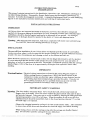
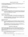
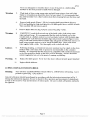
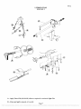
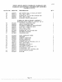
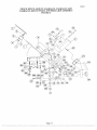
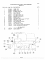
1
INSTRUCTION
MANUAL
DURO series Slicer
Persons under age 18 are not permitted to operate or
have accessibility to operate this equipment per
U.S. Dept. of Labor Employment Standards
Administration Fact Sheet No. ESA91-3.
univex
6512/0304
PDF compression, OCR, web optimization using a watermarked evaluation copy of CVISION PDFCompressor
ED 5
TO INSU RE BOTH SAFE AND
TROUBLE-FREE PERFORMANCE WE
STRESS THAT ALL PERSONNEL THAT
WILL BE INVOLVED WITH YOUR NEW
UNIVEX SLICER MUST READ AND
UNDERSTAND THESE INSTRUCTIONS
BEFORE ATTEMPTING TO OPERATE
THIS UNIT.
WE APPRECIATE YOUR
COOPERATION AND YOUR BUSINESS.
SHOULD THERE BE A QUESTION OR IF
WE CAN BE OF FURTHER ASSISTANCE,
PLEASE CALL US,
1-603-893-6191.
PDF compression, OCR, web optimization using a watermarked evaluation copy of CVISION PDFCompressor
6512
TABLE OF CONTENTS
PAGE
'DESCRIPTION
Table of Contents
1
List of Illustrations
1
Introduction
3
Installation Instruction
3
Safety Warnings
3
Operating Instructions
4-5
Sharpening Instructions
4-5
Operator's Care of Slicer - Cleaning & Lubrication
5-6
8
Mechanic's Maintenance
.,.
Trouble Shooting Guide
Repair Instructions including Disassembly, Replacement, and Reassembly
.
9
10 - 12
13 - 19
Replacement Parts Lists Keyed to Figure Drawings
20
Wiring Diagram
Back Cover
Warranty Information
LIST OF ILLUSTRATIONS
PAGE
ILLUSTRATION
Figure 1
Overall View of Meat Slicer Model 6512
2
Figure 2
Lubrication Diagram and Instructions
7
Figure 3
Knife, Pulley, and Motor Assembly
Figure 4
Fence, Fence Adjustment, Carriage, Carriage Arm, Carriage Ann Support,
and Feed Grip Assembly
13 - 14
15 -17
18
Fìgure 5
Sharpener assembly
Figure 6
Base and Slice Adjustment Knob Assembly
19
Wiring Diagram 115V, 60HZ, 1 PH
20
Figure 7
Page 1
PDF compression, OCR, web optimization using a watermarked evaluation copy of CVISION PDFCompressor
6512
OVERALL VIEW OF MEAT SLICER
MODEL 6512
FIGURE 1
i
FENCE
8
CARRIAGE ARM
2
KNIFE SHARPENER
9
GRADUATED KNOB
3
KNIFE GUARD
10
ON-OFF SWITCH
4
PROTECTIVE GUARD
11
INDICATOR LIGHT
5
LAST SLICE DEVICE
12
CARRIAGE
6
ELECTRIC CORD (NOT SHOWN)
13
SERIAL NAIVIE PLATE
7
CARRIAGE ARM KNOB
(NOT SHOWN)
Page 2
PDF compression, OCR, web optimization using a watermarked evaluation copy of CVISION PDFCompressor
6512
INSTRUCTION MANUAL
INTRODUCTION
This manual contains instructìons for the Installation, Operation, Care, Maintenance and Repair of
the Meat Slicing Machine. Disassembly, Repair, Replacement and Reassembly Instructions are
included. A trouble shooting guide is provìded. A complete Replacement Parts List with identifying
figures is also included to facilitate identification and ordering of replacement parts.
INSTALLATION INSTRUCTIONS
INSPECTION
All Univex slicers are inspected and tested at the factory; however, they should be reinspected
carefully by the person making the installation for loose, damaged or broken parts. Detached parts
and fixtures should be checked against packing list to determine all are present. Any damages,
imperfections or shortages should be reported to the dealer or Univex and shipping carrier.
Warning: After slicer has been inspected, wash slicer completely with warm water and mild soap.
For SAFETY, follow the cleaning instructions on Page 5.
INSTALLATION
The most efficient installation of your Univex slicer will depend upon the layout of your kitchen.
Locate your slicer where it will save steps for the operator and be sure to provide sufficient clearance
around it for ease of maintenance and cleaning, as well as for efficient and safe use.
Slicer should be operated on a sturdy bench or table with the heìght determined to suit the operator.
It is most important that the forearm of the operator be at the proper level for ease and safety of
operation, as well as for maximum production. This height is considered optimum when the carriage
handle (Figure 1 [8]) of the slicer is at approximately the height of the operators elbow when
standing.
IMPORTANT
Warning/Caution: Electrical wiring instructions are found in the wiring diagram (Figure 7)
Before making electrical connections, CHECK the specifications on the
nameplate to make sure that they agree with those on your electrical service.
A grounding type three-terminal plug is provided for safety. If you do not
have a mating receptacle, have a qualified electrician provide one with
grounding provisions in accordance with local safety codes.
IMPORTANT SAFETY WARNINGS
Warning: The slicer knife is extremely sharp! Never touch the knife, always keep hands and
fmgers clear of the knife. Never run slicer without the guard and all other parts in place
and securely fastened. Take extra care to avoid accidents by keeping the knife guard and
sharpening assembly cover ON at all times. When the machine is not in use, the slice
adjustment knob should be turned fully back to the closed position (beyond "O") so that
the knife edge is not exposed.
Observe the cleaning instruction on Page 5 for best results and for safety. Also remember
to always turn off the slicer and disconnect the electrical supply cord before cleaning.
When slicing, always work the carriage using only the carriage arm handle (Figure 1
[8]). Do not hold or push the carriage from any other place.
Page 3
PDF compression, OCR, web optimization using a watermarked evaluation copy of CVISION PDFCompressor
6512
OPERATION INSTRUCTIONS
The Univex slicer is designed to meet the cook's demand for an efficient, sturdy slicer. The Univex
slicer will give un.faìling performance over a period of years, when operated and maintained
according to instructions contained herein.
START/STOP SWITCH
The slicer is started by toggling the ON/OFF switch (Figure 1 [10]) to the ON position. A pilot light
(Figure 1 [11]) is provided to indicate when the slicer is turned on.
SLICE ADJUSTMENT
Warning: Dial-type knob adjustment (Figure 1 [9]) allows for slice thicknesses ranging from paper
thin up to 9/16". Dial graduations allow you to precisely set up specific slice thicknesses
for various needs. When not in use, always return knob back to its fully closed position
(beyond "0") so that the knife edge is not exposed.
POSITIVE HOLD CARRIAGE
Caution: A last slice gravity feed grip (Figure 1 [5]) is provided. Do not use this last slice device
to work the carriage back and forth. Use only the carriage arm handle (Figure 1 [8]).
Always make sure the carriage is positively secured to the slicer by checking to see that
the carriage arm knob (Figure 1 [7]) is frilly tightened. Failure to do this could result in
the carriage striking and damaging the knife edge.
PROTECTIVE GUARD
Warning: The protective guard (Figure 1 [4]) covers the knife edge completely except under the
sharpener cover and the forward edge where slicing will be performed. This forward
edge is covered by the edge of the fence, but only when the slice adjustment is completely
closed.
The knife guard (Figure 1 [3]) can be removed for cleaning by unscrewing the knife
guard knob (Figure 3 [31]). For safety, keep the knife guard on at all times except when
cleaning. Never operate the slicer with the knife guard removed.
SHARPENING INSTRUCTIONS
This slicer is equipped with a knife having a concave or hollowed surface for superior slicing
quality. Of course, any knife, however superior, must be sharpened regularly and properly in order
to produce not only the highest quality slices, but also to allow it to maintain its productivity. The
knife sharpener (Figure 1 [2]) on this machine is a top mounted built-in mechanism, designed for
simplicity and ease of use.
Warning: The following sharpening procedure will provide high quality sharpening results and
should also be followed for safety considerations:
Warning: Keep away from the knife edge.
Completely close the slice adjustment (beyond "O) so that the knife edge is not exposed.
Page 4
PDF compression, OCR, web optimization using a watermarked evaluation copy of CVISION PDFCompressor
6512
The knife cutting area should be clean and free from food, especially grease. Grease will
ruin the ability of a grinding stone to sharpen an edge. The stone simply will not cut. If
cleaning is necessary, follow the procedure outlined on Page 5.
Loosen sharpener knob assembly (Figure 5 [28]) which bears against sharpener post, then
lift sharpener assembly (Figure 1 [2]) and rotate it 1/2 turn (1800). Then force it down
over the knife.
Tighten sharpener knob assembly (Figure 5 [28]). As the knob assembly is tightened, it
bears on the sharpener post and automatically aligns the grinding and deburring stones to
the precise orientations which are preset at our factory.
Turn slicer Q.. Depress the sharpener button on the back side of blade and hold in, which
will start the grinding wheel rotating. Run until the beveled cutting surface cleans up. This
can take from 30 seconds to several minutes depending on how dull the blade was allowed to
become.
Release sharpener button.
Turn slicer Q and check for the formation of a very slight burr on the side of knife opposite
the bevel which indicates complete grinding of the bevel. This slight burr can be detected
either visually or by picking with a small piece of stiff paper.
Turn slicer ON. Lightly press deburring (honing) button on the front side of blade and hold
for 1 to 2 seconds while you turn OFF the slicer. Blade should now be completely sharpened
and honed.
Caution: It is important for best slicing results not to deburr the knife too long or the
keen edge will be destroyed due to the formation of an undesirable second bevel
on the opposite side. This condition tends to be the primary cause of
unsatisfactory slicing results.
Turn slicer OFF. Loosen knob assembly, (Figure 5 [28)) then lift and return sharpener to
its storage position. Tighten knob assembly.
Clean slicer and knife according to the cleaning procedure on Page
thoroughly remove grinding debris.
5
in order to
OPERATORS CARE OF SLICER
CLEANING
Warning:
1.
Never touch the knife edge. Always keep your hands, fmgers and arms clear of
knife.
Warning:
2.
Turn off slicer and DISCONNECT ELECTRICAL CORD before cleaning.
Leave protective guard (Fig. 1 [4]) in place.
3.
Turn slice adjustment knob (Figure 1 [9]) to the fùlly closed position (beyond
"0") so that the knife edge is not exposed.
4.
Remove carriage assembly (Figure 1 [5, 8, 12]) by loosening carriage knob
(Figure 1 [7]) and lifting off. Carriage may be washed in a sink. Use care in
washing the sharply pointed prongs on the last slice device, (Figure 1 [5]). Wash
this area thoroughly. A small bristle brush is recommended. Use only warm
water and mild soap. Rinse carriage assembly with warm water and dry
thoroughly using a clean soft cloth.
Caution:
Page 5
PDF compression, OCR, web optimization using a watermarked evaluation copy of CVISION PDFCompressor
6512
Never use detergents or wash the slicer or any of its parts in a dishwashing
machine or the clear protective finish will be damaged.
Warning
5.
Wash body of slicer using warm water and mild soap using a clean soft cloth.
Under no circumstances should the slicer be hose rinsed. It is recommended that
the cloth be folded over a thin wooden stick when cleaning between the fence and
the knife.
Remove knife guard (Figure 1 [3]) by loosening knife guard knob (Figure 3
[31]) and pushing the long stud upward to lift knife guard above surface of knife.
Then carefully lift and remove guard.
Remove Knife deflector (Fig 4 [9]) by unscrewing (Fig 4 [lO]).
Warning:
8.
CAREFULLY wash the front and rear of the knife with a cloth using warm
water and mild soap. It is recommended that the cloth be folded over a thin
wooden stick as a further caution to avoid accidental contact with the knife edge.
CAREFULLY wash between the knife edge and protective guard (Figure 1 [4])
using a soft cloth inserted between knife edge and guard on both front and rear of
knife using extreme caution to never touch the knife edge. Rinse with warm
water applied with a cloth. Dry thoroughly with a clean soft cloth.
Caution:
9.
Following cleaning, a commercial non-toxic sanitizer may be wiped on the clean
surfaces with a soft clean cloth or sprayed as recommended on the container
labeling. It is important that the sanitizer be compatible with anodized aluminum
or the clear protective finish on the slicer will be damaged. Surface should be
wetted completely, but not to the point of running or puddling.
10.
Replace the knife guard. Never leave the slicer without its knife guard installed!
11.
Replace Knife deflector.
Warning:
LUBRICATION & FUNCTION CHECK
Warning:
Turn off slicer and DISCONNECT ELECTRICAL CORD before lubricating. Leave
protective guard (Fig. 1 [4]) in place.
General lubrication should be performed in accordance with the lubrication instructions in Fig. 2.
During this lubrication sequence, be sure to check for free operation and movement of related parts
as well as for excessive wear and looseness of various parts. Be sure to check all handles and knobs
for tightness.
Page 6
PDF compression, OCR, web optimization using a watermarked evaluation copy of CVISION PDFCompressor
6512
LUBRICATION
FIGURE 2
A - Apply Petro-Gel (4400408) often as required to maintain light film.
B Clean and apply mineral oil weekly.
Page 7
PDF compression, OCR, web optimization using a watermarked evaluation copy of CVISION PDFCompressor
6512
MECHANICS MAINTENANCE
Every year a mechanic or service technician should perform the following inspection and carry out
the respective maintenance as required:
Warning: FOR SAFETY, TURN OFF SLICER AND DISCONNECT ELECTRICAL
CORD.
BELT DRIVE - This drive features a multi-ribbed high performance belt for long
trouble-free service. Inspect belt for proper tension. If glazed or excessively worn,
replace. A tensioning device automatically allows for normal belt wear-in and
stretching. However, if additional tension is required, it may be obtained by turning
adjustment nuts (Fig. 3 [21]) clockwise on take-up rod (Fig. 3 [26]) which will
further compress the tensioning spring. As a guideline, the compressed length of the
spring should be approximately 7/8".
CARRIAGE - Check for free smooth operation of last slice device and for smooth
travel of carriage arm (Fig. 4 [23]). Check for excess backlash between slide bearing
(Fig. 4 [50]) and carriage slide (Fig. 4 [55]). The correct lash (clearance) required
for smooth carriage operation is obtained when a very slight lash or movement can be
detected. Too much lash can result in the carriage striking and damaging the knife
edge. Too little lash results in binding and a loss of smoothness in carriage travel.
Lash is adjusted by loosening lock nut (Fig. 4 [47]) and turning nylon tipped stud
(Fig. 4 [48]) clockwise to reduce lash and counterclockwise to increase lash. Tighten
lock nut while holding nylon tipped stud stationary with a screwdriver so it does not
move. Grease only the side of the carriage slide (Fig. 4 [55]) on which this nylon
tipped stud screw slides. General guidelines: tighten screw until snug and then loosen
1/8 turn and tighten lock nut as described above
LUBRICATION & FUNCTION CHECK - General lubrication should be
performed in accordance with the lubrication instructions in Fig. 2. During this
lubrication sequence, be sure to check for free operation and movement of related
parts as well as for excessive wear and looseness of various parts. Be sure to check
all handles and knobs for tightness.
KNIFE - Check knife edge to see that it has been properly sharpened. If there is any
evidence of incorrect sharpening procedure, such as excessive honing, alert owner and
operator.
Page 8
PDF compression, OCR, web optimization using a watermarked evaluation copy of CVISION PDFCompressor
6512
TROUBLESHOOTING GUIDE 6512
TROUBLE
i Slicer will not operate.
POSSIBLE CAUSE
I.i
Electrical service down.
1.2 Burned switch contacts.
1.3 Motor capacitor defective.
1 .4 Burned out motor.
REMEDY
1 . i Check electrical service.
Replace fuse or reset circuit
breaker as necessary.
1 . 2 Replace switch.
1.3 Replace
1 .4 Remove, test, repair or replace.
2. Motor straining but
will not turn
(humming sound).
2.1 Belt tension too tight.
2.1 Readjust belt tension.
NOTE: Often after a long period
of no use, such as in storage, the
belt flows and takes a set in the
pulley ribs. A slight urging of the
knife with a wooden stick will get
the slicer turning with no ftzrther
problems. Do not use hands to tum
the knife.
3. Slippage of knife
during slicing.
3.1 Loose belt.
3.2 Grease or oil on belt.
3.1 Tighten belt tension.
3.2 Clean pulleys with safety approved
cleaning solvent on soft clean rag.
Replace belt.
4. Motor stalls during
4.1 Knife cutting edge dull or
improperly sharpened
4.1 Sharpen using the procedure
specified. Use care not to use
honing stone longer than the i to 2
slicing,
4.2 Product such as cheese old
and dried out.
4.3 Low voltage service
4.4 Belt tension excessive.
5. Excessive noise.
seconds.
4.2 Reduce thickness of slice.
4.3 Have electrician check service
voltage.
4.4 Readjust belt tension.
5.1 Knife contacting the knife
5.1 Tighten knob which secures guard.
guard.
5.2 Badly worn or frayed drive 5.2 Replace belt.
belt
5.3 Motor pulley and belt
misaligned.
5.4 Loose set screw in motor
pulley.
5.5 Knife contacting deflector.
5.6 Knife contacting sharpener.
5.7 Carriage contacting fence
or knife.
6. Smearing or tearing
when slicing soft
cheese.
6.1 Soft cheese is at room
temperature.
6.2 Knife dirty with hard
dried-on product.
5.3 Realign motor pulley.
5.4 Tighten set screw.
5.5 Adjust deflector.
5.6 Adjust sharpener.
5.7 Tighten knob which secures
carriage.
6.1 Chill soft cheese for best slicing
resulta.
6.2 Clean knife thoroughly.
Page 9
PDF compression, OCR, web optimization using a watermarked evaluation copy of CVISION PDFCompressor
6512
REPAIR INSTRUCTIONS
Including disassembly, replacement, and reassembly.
Warning: Always turn off slicer and disconnect electrical cord before doing any maintenance or
repair on the slicer. Keep guards on at all times. Keep slice adjustment fishy closed so
knife edge is not exposed. Keep sharpener assembly also in place so top of knife edge is
not exposed.
KNIFE REPLACEMENT (FIgure 3)
Warning: Disconnect electrical power cord.
Remove carriage assembly (Figure 1 [8, 12})
Loosen sharpener knob assembly (Figure 5 [4] ), then lift and remove sharpening unit Set
aside.
Remove knife guard knob (Figure 3 [31] ) and carefully remove knife guard (Figure 3
[IO]).
Warning: Using caution to avoid the sharp knife edge, remove the four screws (Figure 3
[il]) that secure knife (Figure 3 [12] ).
Carefully remove knife and set aside with its flat side down flush on a bench so the edge is
not exposed.
Reinstall new knife in the reverse procedures outlined above.
Even though a new knife is very sharp, the sharpening procedure specified on pages 4 and
5 should be performed to true the new knife's bevel to the slicer.
Warning: Worn knife should be disposed of in a safe responsible way, showing concern for others
who may handle it. It is recommended that the edge of the knife be wrapped several
times with heavy tape and that a caution (CAUTION: SHARP EDGE) be written on
both sides of the knife.
KNIFE SEAL
h.
Warning: Disconnect electrical power cord.
Remove knife per knife replacement instructions i through 6.
Remove pulley insert (Figure 3 [8]) by unscrewing. Retain shim washers if any.
Using a small screwdriver, carefully pry and remove the knife seal (Figure 3 [7] ) from
the knife pulley (Figure 3 [6] ).
Apply light film of Petro-Gel on outer diameter and lip of rubber seal.
Clean recess in pulley.
Drive seal into recess in pulley using care to avoid damage to seal. Seal should be seated
uniformly against recess shoulder.
Check pulley insert (Figure 3 [8] ) for small sharp burrs that may have been raised
during its removal. Remove burrs if present with a fine toothed file. If burrs are not
removed, they will destroy the seal very quickly.
Page lO
PDF compression, OCR, web optimization using a watermarked evaluation copy of CVISION PDFCompressor
6512
Reinstall pulley insert and shims that may have been present Apply liberal coating of
Petro-Gel to the seal/insert interface.
Reinstall knife, knife guard and sharpener in the reverse procedure outlined above.
SHARPENING STONES
I.
Warning: Disconnect electrical cord.
Unscrew sharpener knob assembly (Figure 5 [28] ).
Lift up sharpening assembly (Figure 1 [2] ) and remove from slicer.
Using an open end wrench, unscrew cover knob (Figure 5 [1]). It is recommended that a
piece of tape or paper be temporarily wrapped around knob prior to unscrewing it so as to
protect its finish. Remove cover (Figure 5 [2]) off of mount assembly.
Unscrew nut (Figure 5 [191 ) and remove along with washer and sharpening stone
(Figure 5 [21] ).
Install new sharpening stone. Hollowed side should be toward the outside.
Honing (deburring) stone (Figure 5 [12] ) is removed by first unscrewing lock screw
(Figure 5 [17] ) from button (Figure 5 [16] ).
Gently remove button taking care to not lose the small ball bearing and spring (Figure 5
[14 & 15] ) which are inside.
Unscrew nut (Figure 5 [13] ) and remove along with washer and honing stone (Figure 5
[12]).
Install new honing stone with the hollowed side toward the inside.
Reattach cover and reinstall in the reverse procedures (4. through 1.).
DRIVE BELT REPLACEMENT
Warning: Disconnect electrical power cord.
Remove knife per knife replacement instructions.
Remove the 7 screws (Figure 3 [14]) and belt guard (Figure 3 [15]).
Remove four rubber suction feet (Figure 6 [13] ) that secure bottom cover (Figure 6 [12]
to slicer. Remove cover.
Remove nuts (Figure 3 [21] ) from motor adjustment rod (Figure 3 [26] ) so motor can
be pivoted to give belt slack. Be careful not to lose tensioning spring (Figure 3 [19]).
Remove motor pivot bolt (Figure 3 [28]).
Unwrap belt from motor pulley shaft.
Unwrap and remove drive belt from the knife pulley (Figure 3 [6]).
Page 11
PDF compression, OCR, web optimization using a watermarked evaluation copy of CVISION PDFCompressor
6512
Install replacement belt on knife pulley and on motor pulley shaft. DO NOT reinstall
knife at this time.
Reinstall motor pivot bolt.
li.
Reinstall spring and nuts on motor adjustment rod (Figure 3 [26] ) and tighten. It is
important to make sure that the belt ìs aligned on both pulleys.
Belt tension is correct when the spring is compressed to an overall length of 7/8.
Connect electrìcal power cord and operate slicer to check that belt and pulley are
running true.
Turn off slicer and disconnect electrical power cord.
Reinstall bottom cover and secure with the four suction feet.
Reinstall belt guard with 7 screws.
Using caution, reinstall knife and secure with four screws.
Reinstall knife guard and secure with knife guard knob.
Reinstall sharpener and secure with knob assembly.
Page 12
PDF compression, OCR, web optimization using a watermarked evaluation copy of CVISION PDFCompressor
6512
KNIFE, PULLEY AND MOTOR ASSEMBLIES
FIGURE 3
ILLUS. NO. PART NO. DESCRIPTION
1
2
3
4
5
6
7
8
9
10
11
12
13
14
15
16
17
18
19
20
21
22
23
24
25
26
27
28
29
30
31
32
33
6512020
6512021
6512043
6512022
6512044
6512023
6512045
6512024
6512025
6512026
6509014
8512228
1204003
8512229
6512027
6512055
6509005
6509103
6509104
1200076
1200060
6509041
1204006
6512046
6512028
6512029
6512050
6512053
6512051
1204008
6512030
1204005
6509017
6509016
8512871
QTY.
HOUSING, TOP
1
PULLEY ASSEMBLY INCLUDES NO.2 THRU 8
SHAFT, PULLEY
SNAP RING, PULLEY
SPACER, PULLEY
BEARING, PULLEY
PULLEY
SEAL, PULLEY
INSERT, PULLEY
GUARD, PROTECTIVE
GUARD, KNIFE
SCREW, M5.0.8 X 10 FLAT HD SLOTTED
BLADE
SCREW, M5-0.8 X 20 FLAT HD SLOTTED
SCREW, FLAT HD PHIL
GUARD, BELT
BELT
SET SCREW, M8-1.25 X 10 CUP POINT
COLLAR, MOTOR ADJ.
SPRING, MOTOR ADJ.
WASHER, NO. 10 FLAT
NUT, 10-3 2 HEX
WASHER, M6 FLAT
SCREW, M6-1.0 X 18 SOC HEX HD
GROMMET, RUBBER
BRACKET, MOTOR ADJUST
ROD, MOTORADJUST
MOTOR, 115V,6OHZ, 1PH, l/3HP
MOTOR,230V,6OHZ, 1PH
MOTOR, 230V, 50HZ, 1PH
BOLT, HEX HD
HOUSING, BASE
SCREW, M6-1.0 X 20 SOC HEX HD
KNOB, KNIFEGUARD
SHAFT, KNIFE GUARD
PIN, KNIFE GUARD
1
1
2
1
1
1
1
1
5
1
2
7
2
1
2
2
1
1
1
1
1
1
1
1
1
I
4
I
1
Page 13
PDF compression, OCR, web optimization using a watermarked evaluation copy of CVISION PDFCompressor
6512
KNIFE, PULLEY AND MOTOR ASSEMBLY
FIGURE 3
Page 14
PDF compression, OCR, web optimization using a watermarked evaluation copy of CVISION PDFCompressor
6512
FENCE, FENCE ADJUST, CARRIAGE, CARRIAGE ARM
CARRIAGE ARM SUPPORT AND FEED GRIP ASSEMBLY
FIGURE 4
ILLUS. NO. PART NO.
DESCRIPTION
QTY.
FENCE MOUNTING BRACKET AND SHAFT ASSEMBLY
INCLUDES NO. 1 THRU 3
1
2
3
4
5
6
7
8
9
10
11
12
13
14
15
16
17
18
19
20
21
22
23
24
25
26
27
28
6509076
6512031
6509083
SHAFT, FENCE ARM
BRACKET, FENCE MOUNTING
SET SCREW, M6-1.0 X 12 CUP POINT
6509081
6509082
7510080
8512234
8512206
6512033
6509024
6509038
6509037
NUT, ACORNM8-1.25
WASHER
STUD
FENCE
PIN
DEFLECTOR
SCREW, DEFLECTOR
SCREW, FLAT HD SLOTTED
WASHER
CARRIAGE AND FEED GRIP ASSEMBLY
INCLUDES NO. 13 THRU 22
6509158
NYLON TIP
6509053
BUSHING, FEED GRIP
6509159
PIN
6509160
NYLON TIP
6512034
FEED GRIP
6509054
HANDLE, FEED GRIP
6509049
SHAFT, FEED GRIP
6509153
KNOB, FEED GRIP
6512035
CARRIAGE
6509057
BOLT, CARRIAGE LOCK
6512036
6509045
6509044
6509046
6509058
6509059
CARRIAGE ARM ASSEMBLY
INCLUDES NO.23 THRU 25 AND 2 OF 26
ARM, CARRIAGE
HANDLE, CARRIAGE ARM
KNOB, CARRIAGE ARM
SCREW, M6-1.0 X 16 HEX WASHER HD
NUT, ACORN,M10-1.5
WASHER, CARRIAGE ARM
1
2
2
2
2
1
1
2
2
1
2
1
1
1
1
1
1
1
1
1
1
5
1
1
FENCE ADJUSTMENT ASSEMBLY
INCLUDES NO.29 THRU 42, ONLY 1 OF 32,
ONLY I 0F35,AND3OF26
29
30
31
32
33
34
35
36
37
6509060
6509069
6512802
6509132
6509071
8512527
8512326
6509061
6509064
FRAME, FENCE ADJ.
SHAFT, FENCE ADJ.
WASHER, M8 EXTERNAL TOOTH
WASHER, M8 FLAT
PIN, FENCE ARM SHAFT
SCREW,M8-1.25X25HEXHD
SET SCREW, M8-1.25 X 22 CUP POINT
SPRING, FENCE ADJ.
SUPPORT, FENCE ADJ.
1
1
4
1
1
2
1
Page 15
PDF compression, OCR, web optimization using a watermarked evaluation copy of CVISION PDFCompressor
6512
FENCE, FENCE ADJUST, CARRIAGE, CARRIAGE ARM
CARRIAGE ARM SUPPORT AND FEED GRIP ASSEMBLY
FIGURE 4 (CONT.)
ILLUS. NO. PART NO.
38
39
40
41
42
6509073
6509074
6509067
6509072
6509070
DESCRIPTION
QTY.
SET SCREW, M6-I.0 X 20 FLAT POINT
NUT, M6-1.OHEX
SCREW, M6-1.0 X 18 HEX SOCKET HD
NUT, M8-1.25 HEX
SUPPORT, FENCE ARM SHAFT
2
1
CARRIAGE ARM SUPPORT ASSEMBLY
43
44
45
46
47
48
49
50
51
52
53
54
55
56
57
58
59
60
61
62
63
64
8512325
6509042
6509026
6509025
6509033
6509032
8512308
6509031
8512802
INCLUDES NO.43 THRU 51,20F 32, 1 OF 35
ANCHOR, CARRIAGE ARM
BOLT, CARRIAGE ARM
BUSHING, CARRIAGE ARM SUPPORT
SUPPORT, CARRIAGE ARM
NUT, M10-1.5 HEX
1
2
1
1
STUD, NYLON TIP
SCREW, M8-1.25 X 20 HEX HD
BEARING, ROLLER
WASHER LOCK
1
1
6512038
6509036
6509835
6512039
BAR, CARRIAGE SLIDE
1204021
1204007
6509115
1200076
4400101
4400024
4509072
6512052
6509113
6512047
WASHER M8 FLAT
2
SCREW, HEX SOC HD M8-1.25 X 15
NUT, M5-0.8 HEX
2
WASHER, FLAT NO 10
TIE DOWN, CORD
BRACKET, CAPACITOR 115V
3
WASHER
SPRING, SLIDE BAR
2
2
SLIDE, CARRIAGE
CAPACITOR, 115V
CAPACITOR, 230V, 50/60HZ, 1PH
STUD, M5-0.8X25 MM
SPACER
3
1
1
1
1
2
1
Page 16
PDF compression, OCR, web optimization using a watermarked evaluation copy of CVISION PDFCompressor
6512
FENCE, FENCE ADJUST, CARRIAGE, CARRIAGE ARM
CARRIAGE ARM SUPPORT AND FEED GRIP ASSEMBLY
FIGURE 4
Page 17
PDF compression, OCR, web optimization using a watermarked evaluation copy of CVISION PDFCompressor
6512
SHARPENER ASSEMBLY
FIGURE 5
ILLUS. NO.
1
2
3
4
5
6
7
8
9
10
11
12
13
14
15
16
17
18
19
20
21
22
23
24
25
26
27
28
29
PART NO.
DESCRIPTION
6509153
6512054
6509150
6509149
6509137
8512728
6509125
7510120
6509127
6509128
6509129
6509130
6509131
6509134
6509133
6509135
6509136
6509132
6509143
6509144
6509142
6509141
6509126
6512041
6509081
6509121
6512040
7510150
6509147
KNOB
COVER
NUT
SPACER
SCREW
STUD MOUNTING
WASHER, SET PIN
PIN, SET
SPRING
BUSHING
STUD, HONING
STONE, HONING
NUT
SPRING
BALL
BUTTON, STONE DEPRESS
SCREW
WASHER
NUT
WASHER
STONE, SHARPENING
STUD, SHARPENING
MOUNT
SUPPORT, SHARPENER
NUT, ACORN
WASHER
STUD, SHARPENER SUPPORT
KNOB, ASSEMBLY
SCREW, SHARPENER
QTY
I
1
2
1
2
2
1
1
2
2
2
2
1
1
1
1
1
1
1
2
Page 18
PDF compression, OCR, web optimization using a watermarked evaluation copy of CVISION PDFCompressor
6512
BASE & SLICE ADJUSTMENT KNOB ASSEMBLY
FIGURE 6
QTY.
ILLUS. NO. PART NO. DESCRIPTION
1
2
3
4
5
6
7
8
9
10
11
12
13
14
15
16
17
19
20
1012042
4400053
8800210
6509090
6509091
6509088
6509089
7120009
6512042
6509093
7120011
4400081
4400338
4400409
LIGHT, 125V
LIGHT,230V
KNOB, SLICE ADJ
WASHER. SLICE ADJ
NUT, SLICE ADJ
STRAIN RELIEF
ELECTRIC CORD, 115V
ELECTRIC CORD, 230V
HOLDER, CAM INSERT
INSERT, CAM
CAM, SLICE ADJ
SET SCREW, M6-1.0 X 14, CUP POINT
SWITCH, 115V, 220.240V
COVER, BOTTOM
FEET, RUBBER SUCTION
GUARD, SWITCH
PIN, SWITCH GUARD
LABEL, UNI VEX DURO (NOT SHOWN)
LABEL, DANGER (NOT SHOWN)
4400236
4400227
CANADA ONLY
CIRCUIT BREAKER
LABEL, RESET
1814069
1814069A
6509084
6509086
6509087
I
I
1
1
1
1
1
1
1
4
2
1
1
NO. I IN FIGURE 3
hEI
Page 19
PDF compression, OCR, web optimization using a watermarked evaluation copy of CVISION PDFCompressor
6512
WIRING DIAGRAM MODEL 6512
115V, 60HZ, 1PH, 230V, 50/60HZ, 1PH
FIGURE 7
PILOT
/
POWER IN
LIGHT
C APA CIT OP
N
H-Q
WHITE
WHITE
BLACK
BLACK
SWITCH
BLACK
BLACK
L___
GREEN/YELLOW
GREEN
GANADA ONLY
CIRCUIT
PILOT
/
POWER IN
ERE AK ET
LIGHT
CAPACITOR
H-O
o
N
BLACK
BLACK
2
WHITE
WHITE
SWITCH
BLACK
BLACK
WHITE
BLACK
GREEN
BLACK
GREEN/YELLOW
IMPORTANT
Warning: Before making electrical connections, check the specifications on the data plate to assure
they agree with those of your electrical service.
Whenever cleaning or maintenance is being performed, DISCONNECT electrical cord.
Page 20
PDF compression, OCR, web optimization using a watermarked evaluation copy of CVISION PDFCompressor